EP2986993B1 - Method and device for determining power system parameters - Google Patents
Method and device for determining power system parameters Download PDFInfo
- Publication number
- EP2986993B1 EP2986993B1 EP14732822.3A EP14732822A EP2986993B1 EP 2986993 B1 EP2986993 B1 EP 2986993B1 EP 14732822 A EP14732822 A EP 14732822A EP 2986993 B1 EP2986993 B1 EP 2986993B1
- Authority
- EP
- European Patent Office
- Prior art keywords
- electrical insulation
- temperature
- determining
- parameter
- insulation
- Prior art date
- Legal status (The legal status is an assumption and is not a legal conclusion. Google has not performed a legal analysis and makes no representation as to the accuracy of the status listed.)
- Active
Links
- 238000000034 method Methods 0.000 title claims description 36
- 238000009413 insulation Methods 0.000 claims description 42
- 238000010292 electrical insulation Methods 0.000 claims description 33
- 238000012360 testing method Methods 0.000 claims description 31
- 230000004044 response Effects 0.000 claims description 25
- 238000012937 correction Methods 0.000 claims description 24
- 239000000463 material Substances 0.000 claims description 22
- 238000005259 measurement Methods 0.000 claims description 22
- 230000004913 activation Effects 0.000 claims description 13
- 238000004590 computer program Methods 0.000 claims description 9
- 230000000638 stimulation Effects 0.000 claims description 8
- 238000010521 absorption reaction Methods 0.000 claims description 3
- 238000013178 mathematical model Methods 0.000 claims description 2
- 230000004936 stimulating effect Effects 0.000 claims description 2
- 230000006870 function Effects 0.000 description 9
- 239000012774 insulation material Substances 0.000 description 7
- 238000010586 diagram Methods 0.000 description 6
- 230000010287 polarization Effects 0.000 description 6
- 230000008569 process Effects 0.000 description 4
- 239000004020 conductor Substances 0.000 description 3
- 230000008859 change Effects 0.000 description 2
- 230000032683 aging Effects 0.000 description 1
- 230000015556 catabolic process Effects 0.000 description 1
- 229920002678 cellulose Polymers 0.000 description 1
- 239000001913 cellulose Substances 0.000 description 1
- 238000006731 degradation reaction Methods 0.000 description 1
- 239000011810 insulating material Substances 0.000 description 1
- 239000002655 kraft paper Substances 0.000 description 1
- 239000004973 liquid crystal related substance Substances 0.000 description 1
- 230000028161 membrane depolarization Effects 0.000 description 1
- 238000012986 modification Methods 0.000 description 1
- 230000004048 modification Effects 0.000 description 1
- 239000003921 oil Substances 0.000 description 1
- 238000012545 processing Methods 0.000 description 1
Images

Classifications
-
- G—PHYSICS
- G01—MEASURING; TESTING
- G01R—MEASURING ELECTRIC VARIABLES; MEASURING MAGNETIC VARIABLES
- G01R27/00—Arrangements for measuring resistance, reactance, impedance, or electric characteristics derived therefrom
- G01R27/02—Measuring real or complex resistance, reactance, impedance, or other two-pole characteristics derived therefrom, e.g. time constant
- G01R27/26—Measuring inductance or capacitance; Measuring quality factor, e.g. by using the resonance method; Measuring loss factor; Measuring dielectric constants ; Measuring impedance or related variables
- G01R27/2688—Measuring quality factor or dielectric loss, e.g. loss angle, or power factor
-
- G—PHYSICS
- G01—MEASURING; TESTING
- G01R—MEASURING ELECTRIC VARIABLES; MEASURING MAGNETIC VARIABLES
- G01R31/00—Arrangements for testing electric properties; Arrangements for locating electric faults; Arrangements for electrical testing characterised by what is being tested not provided for elsewhere
- G01R31/12—Testing dielectric strength or breakdown voltage ; Testing or monitoring effectiveness or level of insulation, e.g. of a cable or of an apparatus, for example using partial discharge measurements; Electrostatic testing
- G01R31/14—Circuits therefor, e.g. for generating test voltages, sensing circuits
-
- G—PHYSICS
- G01—MEASURING; TESTING
- G01N—INVESTIGATING OR ANALYSING MATERIALS BY DETERMINING THEIR CHEMICAL OR PHYSICAL PROPERTIES
- G01N27/00—Investigating or analysing materials by the use of electric, electrochemical, or magnetic means
- G01N27/02—Investigating or analysing materials by the use of electric, electrochemical, or magnetic means by investigating impedance
- G01N27/04—Investigating or analysing materials by the use of electric, electrochemical, or magnetic means by investigating impedance by investigating resistance
- G01N27/048—Investigating or analysing materials by the use of electric, electrochemical, or magnetic means by investigating impedance by investigating resistance for determining moisture content of the material
-
- G—PHYSICS
- G01—MEASURING; TESTING
- G01N—INVESTIGATING OR ANALYSING MATERIALS BY DETERMINING THEIR CHEMICAL OR PHYSICAL PROPERTIES
- G01N27/00—Investigating or analysing materials by the use of electric, electrochemical, or magnetic means
- G01N27/02—Investigating or analysing materials by the use of electric, electrochemical, or magnetic means by investigating impedance
- G01N27/22—Investigating or analysing materials by the use of electric, electrochemical, or magnetic means by investigating impedance by investigating capacitance
- G01N27/221—Investigating or analysing materials by the use of electric, electrochemical, or magnetic means by investigating impedance by investigating capacitance by investigating the dielectric properties
-
- G—PHYSICS
- G01—MEASURING; TESTING
- G01N—INVESTIGATING OR ANALYSING MATERIALS BY DETERMINING THEIR CHEMICAL OR PHYSICAL PROPERTIES
- G01N27/00—Investigating or analysing materials by the use of electric, electrochemical, or magnetic means
- G01N27/02—Investigating or analysing materials by the use of electric, electrochemical, or magnetic means by investigating impedance
- G01N27/22—Investigating or analysing materials by the use of electric, electrochemical, or magnetic means by investigating impedance by investigating capacitance
- G01N27/223—Investigating or analysing materials by the use of electric, electrochemical, or magnetic means by investigating impedance by investigating capacitance for determining moisture content, e.g. humidity
-
- G—PHYSICS
- G01—MEASURING; TESTING
- G01R—MEASURING ELECTRIC VARIABLES; MEASURING MAGNETIC VARIABLES
- G01R31/00—Arrangements for testing electric properties; Arrangements for locating electric faults; Arrangements for electrical testing characterised by what is being tested not provided for elsewhere
- G01R31/12—Testing dielectric strength or breakdown voltage ; Testing or monitoring effectiveness or level of insulation, e.g. of a cable or of an apparatus, for example using partial discharge measurements; Electrostatic testing
- G01R31/1227—Testing dielectric strength or breakdown voltage ; Testing or monitoring effectiveness or level of insulation, e.g. of a cable or of an apparatus, for example using partial discharge measurements; Electrostatic testing of components, parts or materials
- G01R31/1263—Testing dielectric strength or breakdown voltage ; Testing or monitoring effectiveness or level of insulation, e.g. of a cable or of an apparatus, for example using partial discharge measurements; Electrostatic testing of components, parts or materials of solid or fluid materials, e.g. insulation films, bulk material; of semiconductors or LV electronic components or parts; of cable, line or wire insulation
- G01R31/1272—Testing dielectric strength or breakdown voltage ; Testing or monitoring effectiveness or level of insulation, e.g. of a cable or of an apparatus, for example using partial discharge measurements; Electrostatic testing of components, parts or materials of solid or fluid materials, e.g. insulation films, bulk material; of semiconductors or LV electronic components or parts; of cable, line or wire insulation of cable, line or wire insulation, e.g. using partial discharge measurements
-
- G—PHYSICS
- G01—MEASURING; TESTING
- G01R—MEASURING ELECTRIC VARIABLES; MEASURING MAGNETIC VARIABLES
- G01R31/00—Arrangements for testing electric properties; Arrangements for locating electric faults; Arrangements for electrical testing characterised by what is being tested not provided for elsewhere
- G01R31/50—Testing of electric apparatus, lines, cables or components for short-circuits, continuity, leakage current or incorrect line connections
- G01R31/62—Testing of transformers
-
- G—PHYSICS
- G01—MEASURING; TESTING
- G01R—MEASURING ELECTRIC VARIABLES; MEASURING MAGNETIC VARIABLES
- G01R31/00—Arrangements for testing electric properties; Arrangements for locating electric faults; Arrangements for electrical testing characterised by what is being tested not provided for elsewhere
- G01R31/34—Testing dynamo-electric machines
Definitions
- the present invention relates generally to measuring and determining a dielectric parameter of an electrical insulation of a power system component and more particularly a method and a device for determining parameters taking into account the characteristics of the individual insulation properties.
- Testing the insulation system of power system components may be conducted by connecting a test set to two conductors separated by an insulation system and exciting one conductor with the other conductor as a reference with electrical signals, either with a DC signal, an AC signal or an arbitrary waveform signal.
- Methods and apparatuses for measuring the degradation of the insulation of electrical power devices are known, like those ones of US 7,659,728 B1 .
- the base temperature is normally in range of 15-40°C, e.g. 20°C.
- An object of the present invention is to provide a method and a device for determining power system insulation parameters, wherein the individual characteristics of the power system apparatus insulation is taken into account.
- a method for determining a dielectric parameter of an electrical insulation of a power system component comprising the following steps: determining the activation energy of the electrical insulation, determining the actual temperature of the electrical insulation and the temperature to which the measurement is to be corrected, calculating a correction factor by means of the Arrhenius equation, stimulating the electrical insulation with a DC voltage stimulation signal; determining a response for the power system to the DC voltage stimulation signal at the actual temperature, and determining the parameter of the electrical insulation at the temperature to which the measurement is to be corrected based on the response modified by means of the correction factor.
- the step of determining the parameter of the electrical insulation is performed in the frequency domain.
- the frequencies are shifted by the correction factor.
- the step of determining the parameter of the electrical insulation is performed in the time domain.
- the time is shifted by the correction factor and the amplitude is scaled for the insulation resistance/ current reading by the correction factor.
- the electrical insulation comprises one single material, and wherein the parameter of the electrical insulation is determined based on the response modified by means of the correction factor calculated based on one single activation energy.
- the electrical insulation comprises at least two materials.
- the steps of conducting a measurement of dielectric response as function of time at the actual temperature of the electrical insulation and dividing the measurement data into data for first, second, and any further material.
- the step of dividing the measurement data into data for first, second, and any further material is performed by means of a mathematical model, preferably the XY model for dielectric frequency response measurements.
- the temperature correction is used for each material, the method comprising the additional step of determining the total dielectric response at the temperature to which the measurement is to be corrected.
- the dielectric parameter is any of the following: insulation resistance, dielectric absorption ratio, and polarisation index.
- the power system component is any of the following: a rotating machine, a transformer, a bushing and a power cable.
- a correction is performed for several temperatures in an interval for determining the temperature dependence of the dielectric parameter, preferably insulation resistance and polarisation index.
- a device for determining a dielectric parameter of an electrical insulation of a power system component comprising a test controller, a stimulator circuit adapted to stimulate the insulation of the power system component, a detector circuit adapted to detect, record, and/or measure the response of the power system component, an input device adapted to input test values and/or parameter values to command the stimulator circuit, and an output device, wherein the device is , characterized in that the test controller is adapted to control the device to perform the method according to the invention.
- a computer program comprising computer readable code means, which when run in a device causes the device to perform the above mentioned method.
- a computer program product comprising a computer program comprising computer readable code means, which when run in a device causes the device to perform the above mentioned method.
- a correction in the frequency domain, where ⁇ represents the frequency, is performed as follows.
- ⁇ ⁇ , T 2 A y /A x ⁇ ⁇ ⁇ / A x T 1, T 2 , T 1
- DF e.g. 0.0023
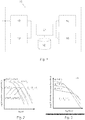
- Fig. 4 shows the dissipation factor as a function of frequency. It is there seen how the dissipation measured at 40°C is adjusted by means of the Arrhenius or correction factor to obtain the dissipation factor at 20°C.
- a correction in the time domain is performed as follows.
- f t , T 2 A y T 1, T 2 * f A x T 1, T 2 * t , T 1
- I t , T 2 A xy T 1, T 2 * I A xy T 1, T 2 * t , T 1
- IR e.g. 1.0 GOhm
- the device 10 comprises a test controller 11, a stimulator circuit 12, a detector circuit 13, an input device 14, an output or display device 15, and an optional database 16.
- the device may be connected to an electrical power system apparatus by means of a harness or the like (not shown).
- the test controller 11 may comprise a computer program, comprising computer readable code means, which when run in a device causes the device to perform the method as described below. Also the test controller may comprise a computer program product comprising such a computer program.
- the stimulator circuit 12 stimulates or excites the insulation of the power system component under test with a stimulation signal.
- the stimulator circuit 12 may generate a direct current (DC) voltage signal to stimulate the component under test.
- DC direct current
- the detector circuit 13 detects, records, and/or measures the response of the component under test to the stimulation signal output by the stimulator 12.
- the detector circuit 13 may include one or more analogue-to-digital converters to periodically capture the voltage and/or current of an output of the component under test and other circuitry to store the digital values in a memory.
- the detector circuit 13 may include other circuitry or processing functionality to analyze the captured response to determine a test result parameter, for example polarization current, depolarization current, insulation resistance, dielectric absorption ratio and polarization index.
- the detector circuit 13 provides unprocessed data to the test controller 11, which analyzes the unprocessed data to determine the test result parameter.
- the test controller 11 conducts the test by controlling the stimulator circuit 12 and the detector circuit 13.
- the test controller 11 receives inputs from the input device 14 that the test controller 11 uses to define test values and/or parameter values to command the stimulator circuit 12.
- the inputs may define an insulation temperature of the power system component under test and/or an ambient temperature of the environment surrounding the power system component under test.
- the input device 14 may be a keyboard and/or keypad and/or touch screen.
- the display device 15 may be a flat panel display, a liquid crystal display (LCD), or other display.
- the device 10 may be coupled to local AC power and to a printer at the test location, in the field, to print out test results on location.
- a method for determining a dielectric parameter of an electrical insulation of a power system component will now be described in detail.
- the method described in a general way comprises the following steps. Although these steps are described in a specific order, it will be appreciated that the order may be changed without deviating from the inventive idea.
- T1 i.e., the actual specimen temperature
- T2 the temperature you would like to "correct” your measured data to
- the activation energy Exy of the electrical insulation of the power system component to be tested is determined.
- the activation energy is about 0.9 eV for oil-impregnated cellulose, such as Kraft paper and pressboard, and is about 0.4-0.5 eV for transformer oils.
- the activation energy for other materials can be found in literature or by measurements.
- the actual temperature T1 of the electrical insulation is also determined. This can be done in many ways known to the person skilled in the art.
- the electrical insulation is stimulated with a DC voltage stimulation signal for a suitable time, such as 6.2 seconds, 60 seconds or any other suitable time.
- the response of the electrical insulation to the DC voltage stimulation signal is then determined.
- the parameter of a power system component is determined.
- Fig. 2 depicts possible temperature dependence of a material when measured in frequency domain (AC).
- frequency domain the frequencies are shifted by the factor Axy calculated by Arrhenius equation based on T1 and T2 and the activation energy for the specific insulation material.
- an oil-impregnated insulation system measured at 40°C has a dissipation factor of 0.0021 at 50 Hz and about 0.0028 at 485Hz it will have about 0.0028 at 50Hz and 20°C.
- 20°C difference means approximately a factor of 1/0.103 in frequency for an insulation material with activation energy of 0.9eV.
- Fig. 3 depicts possible temperature dependence of a material when measured in time domain (DC).
- time domain the same scaling factor is used as the one used in the frequency domain but the time is shifted and the amplitude is scaled for the insulation resistance / current reading.
- the same oil-impregnated insulation system as above is measured at 40°C.
- the equivalent reading now is 9.7 GOhm (1 GOhm/0.103) at 60 seconds (6.2/0.103) for 20°C.
- the insulation resistance is measured at another time, wherein the scaling factor is determined by the temperature difference T1 - T2 and the activation energy and the insulation resistance/current is multiplied/divided with same scaling factor.
- Fig. 5 wherein the insulation resistance is show as a function of time.
- the lower curve is the insulation resistance measured at 40°C and by adjusting it in time and scaling it with the Arrhenius or correction factor, the upper curve is obtained representing the insulation resistance at 20°C.
- the parameter of the electrical insulation at T2 is determined based on the response modified by means of the correction factor for the single material, i.e., with one single activation energy. If the electrical insulation comprises two or more materials, the method must be applied individually for each of the two or more materials according to the following.
- a dielectric parameter insulation resistance (IR), polarisation current or depolarisation current
- IR insulation resistance
- depolarisation current depolarisation current
- the total dielectric response is determined, using same model as when the materials were separated, e.g. the XY model, at the temperature to which the measurement is to be corrected.
- the result can be used as to calculate an equivalent dielectric parameter e.g. insulation resistance and polarisation index, for one single insulation material.
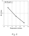
- the dielectric response can be determined, e.g., insulation resistance and polarisation index, for a number of different temperatures and the dielectric response is plotted at for example insulation resistance at 60 seconds as a function of the temperature. This is exemplified in Fig. 6 , showing the insulation resistance at 60 seconds as a function of temperature.
- the power system component test device may readily be employed for testing dielectric properties in power system components, including power transformers, instrument transformers, cables, generators, and other rotating machines, circuit breakers, and others, in some cases after making appropriate modifications to the stimulator circuit 12 or detector circuit 13 or test controller 11.
Landscapes
- General Physics & Mathematics (AREA)
- Physics & Mathematics (AREA)
- Chemical & Material Sciences (AREA)
- Life Sciences & Earth Sciences (AREA)
- Chemical Kinetics & Catalysis (AREA)
- Electrochemistry (AREA)
- Health & Medical Sciences (AREA)
- Analytical Chemistry (AREA)
- Biochemistry (AREA)
- General Health & Medical Sciences (AREA)
- Immunology (AREA)
- Pathology (AREA)
- Power Engineering (AREA)
- Engineering & Computer Science (AREA)
- Testing Relating To Insulation (AREA)
- Measurement Of Resistance Or Impedance (AREA)
Description
- The present invention relates generally to measuring and determining a dielectric parameter of an electrical insulation of a power system component and more particularly a method and a device for determining parameters taking into account the characteristics of the individual insulation properties.
- Testing the insulation system of power system components, such as transformers, rotating machines and cables, may be conducted by connecting a test set to two conductors separated by an insulation system and exciting one conductor with the other conductor as a reference with electrical signals, either with a DC signal, an AC signal or an arbitrary waveform signal. Methods and apparatuses for measuring the degradation of the insulation of electrical power devices are known, like those ones of
US 7,659,728 B1 . - It is known that an increase in temperature causes a decrease of the insulation resistance. Therefore, the temperature has a high influence on insulation resistance measurements and the results should be corrected to a base temperature. The base temperature is normally in range of 15-40°C, e.g. 20°C.
- It is also known to use tables with temperature correction factors with standard values for correcting the results to a base temperature. However, these factors do not take into account the characteristics of the insulation properties, which may change with aging status of the specific apparatus.
- An object of the present invention is to provide a method and a device for determining power system insulation parameters, wherein the individual characteristics of the power system apparatus insulation is taken into account.
- According to a first aspect of the invention there is provided a method for determining a dielectric parameter of an electrical insulation of a power system component, comprising the following steps: determining the activation energy of the electrical insulation, determining the actual temperature of the electrical insulation and the temperature to which the measurement is to be corrected, calculating a correction factor by means of the Arrhenius equation, stimulating the electrical insulation with a DC voltage stimulation signal; determining a response for the power system to the DC voltage stimulation signal at the actual temperature, and determining the parameter of the electrical insulation at the temperature to which the measurement is to be corrected based on the response modified by means of the correction factor. Thereby, the individual characteristics of the power system apparatus insulation is taken into account.
- In a preferred embodiment, the step of determining the parameter of the electrical insulation is performed in the frequency domain.
- In a preferred embodiment, the frequencies are shifted by the correction factor.
- In a preferred embodiment, the step of determining the parameter of the electrical insulation is performed in the time domain.
- In a preferred embodiment, the time is shifted by the correction factor and the amplitude is scaled for the insulation resistance/ current reading by the correction factor.
- In a preferred embodiment, the electrical insulation comprises one single material, and wherein the parameter of the electrical insulation is determined based on the response modified by means of the correction factor calculated based on one single activation energy.
- In a preferred embodiment, the electrical insulation comprises at least two materials.
- In a preferred embodiment, the steps of conducting a measurement of dielectric response as function of time at the actual temperature of the electrical insulation, and dividing the measurement data into data for first, second, and any further material.
- In a preferred embodiment, the step of dividing the measurement data into data for first, second, and any further material is performed by means of a mathematical model, preferably the XY model for dielectric frequency response measurements.
- In a preferred embodiment, the temperature correction is used for each material, the method comprising the additional step of determining the total dielectric response at the temperature to which the measurement is to be corrected.
- In a preferred embodiment, the dielectric parameter is any of the following: insulation resistance, dielectric absorption ratio, and polarisation index.
- In a preferred embodiment, the power system component is any of the following: a rotating machine, a transformer, a bushing and a power cable.
- In a preferred embodiment, a correction is performed for several temperatures in an interval for determining the temperature dependence of the dielectric parameter, preferably insulation resistance and polarisation index.
- According to a second aspect of the invention there is provided a device for determining a dielectric parameter of an electrical insulation of a power system component, comprising a test controller, a stimulator circuit adapted to stimulate the insulation of the power system component, a detector circuit adapted to detect, record, and/or measure the response of the power system component, an input device adapted to input test values and/or parameter values to command the stimulator circuit, and an output device, wherein the device is , characterized in that the test controller is adapted to control the device to perform the method according to the invention.
- According to a third aspect of the invention there is provided a computer program, comprising computer readable code means, which when run in a device causes the device to perform the above mentioned method.
- According to a fourth aspect of the invention there is provided a computer program product comprising a computer program comprising computer readable code means, which when run in a device causes the device to perform the above mentioned method.
- The invention is now described, by way of example, with reference to the accompanying drawings, in which:
-
Fig. 1 is a block diagram showing a device according to the invention for determining power system parameters; -
Fig. 2 is a diagram showing possible temperature dependence of a material when measured in frequency domain; -
Fig. 3 is a diagram showing possible temperature dependence of a material when measured in time domain; -
Fig. 4 is a diagram showing dissipation factor as a function of frequency; -
Fig. 5 is a diagram showing insulation resistance as a function of time; and -
Fig. 6 is a diagram showing insulation resistance at 60 seconds as a function of temperature. - In the following, a detailed description of a method and a device for determining a parameter of a power system component will be given.
- Temperature dependence in many insulating materials can be described by the Arrhenius equations:

Assume the activation energy = 0.90 eV and T1 =40°C (=313.15K) and T2=20°C (=293.15K), then
- A correction in the frequency domain, where ω represents the frequency, is performed as follows.

- For insulation materials that follow the Arrhenius equation, Ax=Ay=Axy and then:


- If DF is to be corrected to 50 Hz and 20°C from a measurement at T1 =40°C, then the measuring is conducted at about 485 Hz (50/0.103=485Hz). Measured DF at T1 =40°C is then corrected back:

- Or, since in this formula angle frequency/frequency, temperature in Celsius/Kelvin scale the
same 
- DF, e.g. 0.0023, measured at T1 =40°C and at frequency 485 Hz is the same as DF at
frequency 50 Hz for temperature T2=20°C (i.e. also e.g. 0.0023). This is exemplified inFig. 4 , showing the dissipation factor as a function of frequency. It is there seen how the dissipation measured at 40°C is adjusted by means of the Arrhenius or correction factor to obtain the dissipation factor at 20°C. - A correction in the time domain is performed as follows.

- For insulation materials that follow the Arrhenius equation, Ax=Ay=Axy□ and then


- If IR is to be corrected to 60 s and 20°C, then measuring of the insulation resistance is done at about 6.2 s (0.103*60=6.2). Measured data at T1 =40°C is then corrected back:

same 
- IR, e.g. 1.0 GOhm, measured at T1 =40°C and at a time 6.2 s is the same as IR = 9.7 GOhm (1.0 GOhm / 0.103) at time = 60 s for temperature T2 = 20°C.
- Turning now to
Fig. 1 , a device for determining insulation parameters, generally designated 10, is shown. Thedevice 10 comprises atest controller 11, astimulator circuit 12, adetector circuit 13, aninput device 14, an output ordisplay device 15, and anoptional database 16. The device may be connected to an electrical power system apparatus by means of a harness or the like (not shown). - The
test controller 11 may comprise a computer program, comprising computer readable code means, which when run in a device causes the device to perform the method as described below. Also the test controller may comprise a computer program product comprising such a computer program. - The
stimulator circuit 12 stimulates or excites the insulation of the power system component under test with a stimulation signal. For example, thestimulator circuit 12 may generate a direct current (DC) voltage signal to stimulate the component under test. - The
detector circuit 13 detects, records, and/or measures the response of the component under test to the stimulation signal output by thestimulator 12. Thedetector circuit 13 may include one or more analogue-to-digital converters to periodically capture the voltage and/or current of an output of the component under test and other circuitry to store the digital values in a memory. In an embodiment, thedetector circuit 13 may include other circuitry or processing functionality to analyze the captured response to determine a test result parameter, for example polarization current, depolarization current, insulation resistance, dielectric absorption ratio and polarization index. Alternatively, thedetector circuit 13 provides unprocessed data to thetest controller 11, which analyzes the unprocessed data to determine the test result parameter. - The
test controller 11 conducts the test by controlling thestimulator circuit 12 and thedetector circuit 13. Thetest controller 11 receives inputs from theinput device 14 that thetest controller 11 uses to define test values and/or parameter values to command thestimulator circuit 12. The inputs may define an insulation temperature of the power system component under test and/or an ambient temperature of the environment surrounding the power system component under test. - The
input device 14 may be a keyboard and/or keypad and/or touch screen. Thedisplay device 15 may be a flat panel display, a liquid crystal display (LCD), or other display. - The
device 10 may be coupled to local AC power and to a printer at the test location, in the field, to print out test results on location. - A method for determining a dielectric parameter of an electrical insulation of a power system component will now be described in detail. The method described in a general way comprises the following steps. Although these steps are described in a specific order, it will be appreciated that the order may be changed without deviating from the inventive idea.
- The testing is assumed to be performed at the temperature T1, i.e., the actual specimen temperature, while in the following the temperature you would like to "correct" your measured data to, is designated T2.
- The activation energy Exy of the electrical insulation of the power system component to be tested is determined. The activation energy is about 0.9 eV for oil-impregnated cellulose, such as Kraft paper and pressboard, and is about 0.4-0.5 eV for transformer oils. The activation energy for other materials can be found in literature or by measurements.
- The actual temperature T1 of the electrical insulation is also determined. This can be done in many ways known to the person skilled in the art. The temperature T2 to which the measurement is to be corrected is also determined. Commonly, T2 = 40°C for rotating machines and T2 = 20°C for transformers while T2 = 16°C (60 °F) for cables.
- Using the values of Exy, T1, and T2 in the Arrhenius equation, the temperature dependence or Arrhenius factor Axy (T1, T2) used as a correction factor is calculated.
- The electrical insulation is stimulated with a DC voltage stimulation signal for a suitable time, such as 6.2 seconds, 60 seconds or any other suitable time. The response of the electrical insulation to the DC voltage stimulation signal is then determined. Finally, based on the response, modified using the correction factor, the parameter of a power system component is determined.
-
Fig. 2 depicts possible temperature dependence of a material when measured in frequency domain (AC). In frequency domain the frequencies are shifted by the factor Axy calculated by Arrhenius equation based on T1 and T2 and the activation energy for the specific insulation material. - For example, if an oil-impregnated insulation system measured at 40°C has a dissipation factor of 0.0021 at 50 Hz and about 0.0028 at 485Hz it will have about 0.0028 at 50Hz and 20°C. 20°C difference means approximately a factor of 1/0.103 in frequency for an insulation material with activation energy of 0.9eV.
-
Fig. 3 depicts possible temperature dependence of a material when measured in time domain (DC). In time domain the same scaling factor is used as the one used in the frequency domain but the time is shifted and the amplitude is scaled for the insulation resistance / current reading. - For example, the same oil-impregnated insulation system as above is measured at 40°C. For a measurement result of e.g. 1 GOhm at time 6.2 s, the equivalent reading now is 9.7 GOhm (1 GOhm/0.103) at 60 seconds (6.2/0.103) for 20°C. In other words, if an insulation resistance reading at a specific time is of interest, e.g. at 60 s at 20°C, and the insulation temperature is not 20°C, the insulation resistance is measured at another time, wherein the scaling factor is determined by the temperature difference T1 - T2 and the activation energy and the insulation resistance/current is multiplied/divided with same scaling factor. This is exemplified in
Fig. 5 , wherein the insulation resistance is show as a function of time. The lower curve is the insulation resistance measured at 40°C and by adjusting it in time and scaling it with the Arrhenius or correction factor, the upper curve is obtained representing the insulation resistance at 20°C. - In the example above, wherein the electrical insulation comprises one single material, the parameter of the electrical insulation at T2 is determined based on the response modified by means of the correction factor for the single material, i.e., with one single activation energy. If the electrical insulation comprises two or more materials, the method must be applied individually for each of the two or more materials according to the following.
- First, a dielectric parameter, insulation resistance (IR), polarisation current or depolarisation current, is measured in a time interval at the actual temperature of the insulation, T1, and dielectric response is obtained as a function of time. Then, by means of a model, such as the known XY model for dielectric frequency response measurements, the measurement data is divided into data for first, second, and any further material.
- Using the Arrhenius factor for each material, it is determined how the response is to be transformed for a given temperature change to the temperature T2.
- Finally, the total dielectric response is determined, using same model as when the materials were separated, e.g. the XY model, at the temperature to which the measurement is to be corrected.
- The result can be used as to calculate an equivalent dielectric parameter e.g. insulation resistance and polarisation index, for one single insulation material. Also, the dielectric response can be determined, e.g., insulation resistance and polarisation index, for a number of different temperatures and the dielectric response is plotted at for example insulation resistance at 60 seconds as a function of the temperature. This is exemplified in
Fig. 6 , showing the insulation resistance at 60 seconds as a function of temperature. - Preferred embodiments of a method and a device according to the invention have been described. It will be appreciated by one skilled in the art that the power system component test device may readily be employed for testing dielectric properties in power system components, including power transformers, instrument transformers, cables, generators, and other rotating machines, circuit breakers, and others, in some cases after making appropriate modifications to the
stimulator circuit 12 ordetector circuit 13 ortest controller 11.
Claims (16)
- A method for determining a temperature dependency of a dielectric parameter of an electrical insulation of a power system component, comprising the following steps:- determining the activation energy of the electrical insulation,- determining the actual temperature (T1) of the electrical insulation and the temperature (T2) to which the measurement is to be corrected,- calculating a correction factor (Axy) by means of the Arrhenius equation,- stimulating the electrical insulation with a DC voltage stimulation signal;- determining a response for the power system to the DC voltage stimulation signal at the actual temperature, and- calculating the parameter of the electrical insulation at the temperature to which the measurement is to be corrected based on the response modified by means of the correction factor.
- The method according to claim 1, wherein the step of determining the parameter of the electrical insulation is performed in the frequency domain
- The method according to claim 2, wherein the frequencies are shifted by the correction factor (Axy).
- The method according to claim 1, wherein the step of determining the parameter of the electrical insulation is performed in the time domain.
- The method according to claim 4, wherein the time is shifted by the correction factor (Axy) and the amplitude is scaled for the insulation resistance/ current reading by the correction factor (Axy).
- The method according to any one of claims 1-5, wherein the electrical insulation comprises one single material, and wherein the parameter of the electrical insulation is calculated based on the response modified by means of the correction factor calculated based on one single activation energy.
- The method according to any one of claims 1-5, wherein the electrical insulation comprises at least two materials.
- The method according to claim 7, comprising the steps of conducting a measurement of dielectric response as function of time at the actual temperature (T1) of the electrical insulation, and dividing the measurement data into data for first, second, and any further material.
- The method according to claim 8, wherein the step of dividing the measurement data into data for first, second, and any further material is performed by means of a mathematical model, such as the XY model for dielectric frequency response measurements.
- The method according to claim 8 or 9, wherein the temperature correction is used for each material, the method comprising the additional step of determining the total dielectric response at the temperature to which the measurement is to be corrected.
- The method according to any one of claims 1-10, wherein the dielectric parameter is any of the following: insulation resistance, dielectric absorption ratio, and polarisation index.
- The method according to any one of claims 1-11, wherein the power system component is any of the following: a rotating machine, a transformer, a bushing and a power cable.
- The method according to any one of claims 1-12, wherein a correction is performed for several temperatures in an interval for determining the temperature dependence of the dielectric parameter, preferably insulation resistance and polarisation index.
- A device for determining a temperature dependency of a dielectric parameter of an electrical insulation of a power system component, comprising a test controller (11), a stimulator circuit (12) adapted to stimulate the insulation of the power system component, a detector circuit (13) adapted to detect, record, and/or measure the response of the power system component, an input device (14) adapted to input test values and/or parameter values to command the stimulator circuit (12), and an output device (15), characterized in that the test controller (11) is adapted to control the device to perform all the steps of the method according to claim 1.
- A computer program, comprising computer readable code means, which when run in a device causes the device to perform all the steps of the method according to any of claims 1-13.
- A computer program product comprising a computer program according to claim 15.
Priority Applications (2)
| Application Number | Priority Date | Filing Date | Title |
|---|---|---|---|
| PL14732822T PL2986993T3 (en) | 2013-04-16 | 2014-04-15 | Method and device for determining power system parameters |
| SI201430747T SI2986993T1 (en) | 2013-04-16 | 2014-04-15 | Method and device for determining power system parameters |
Applications Claiming Priority (2)
| Application Number | Priority Date | Filing Date | Title |
|---|---|---|---|
| SE1300282A SE537145C2 (en) | 2013-04-16 | 2013-04-16 | Method and apparatus for determining power system parameters |
| PCT/EP2014/057586 WO2014170306A1 (en) | 2013-04-16 | 2014-04-15 | Method and device for determining power system parameters |
Publications (2)
| Publication Number | Publication Date |
|---|---|
| EP2986993A1 EP2986993A1 (en) | 2016-02-24 |
| EP2986993B1 true EP2986993B1 (en) | 2018-03-07 |
Family
ID=51014256
Family Applications (1)
| Application Number | Title | Priority Date | Filing Date |
|---|---|---|---|
| EP14732822.3A Active EP2986993B1 (en) | 2013-04-16 | 2014-04-15 | Method and device for determining power system parameters |
Country Status (9)
| Country | Link |
|---|---|
| US (1) | US20160041219A1 (en) |
| EP (1) | EP2986993B1 (en) |
| LT (1) | LT2986993T (en) |
| NO (1) | NO2986993T3 (en) |
| PL (1) | PL2986993T3 (en) |
| SE (1) | SE537145C2 (en) |
| SI (1) | SI2986993T1 (en) |
| TR (1) | TR201807880T4 (en) |
| WO (1) | WO2014170306A1 (en) |
Cited By (1)
| Publication number | Priority date | Publication date | Assignee | Title |
|---|---|---|---|---|
| CN110501366A (en) * | 2019-08-30 | 2019-11-26 | 中南大学 | A kind of prediction technique of low-dimensional functional composite material temperature relevant equivalent electric property |
Families Citing this family (13)
| Publication number | Priority date | Publication date | Assignee | Title |
|---|---|---|---|---|
| US10602082B2 (en) | 2014-09-17 | 2020-03-24 | Fluke Corporation | Triggered operation and/or recording of test and measurement or imaging tools |
| US10271020B2 (en) | 2014-10-24 | 2019-04-23 | Fluke Corporation | Imaging system employing fixed, modular mobile, and portable infrared cameras with ability to receive, communicate, and display data and images with proximity detection |
| US20160131607A1 (en) * | 2014-11-06 | 2016-05-12 | Fluke Corporation | Method of combined use of infrared camera, non-contact infrared sensor, or contact temperature sensor with insulation resistance tester for automatic temperature normalization |
| US20170078544A1 (en) | 2015-09-16 | 2017-03-16 | Fluke Corporation | Electrical isolation for a camera in a test and measurement tool |
| WO2017070629A1 (en) | 2015-10-23 | 2017-04-27 | Fluke Corporation | Imaging tool for vibration and/or misalignment analysis |
| EP3370073B1 (en) | 2017-03-01 | 2020-04-29 | ABB Power Grids Switzerland AG | Method and device for determining capacitive component parameters |
| CN109142995B (en) * | 2018-07-31 | 2024-03-19 | 国网江西省电力有限公司南昌供电分公司 | Oil paper insulation dielectric tester and method based on dielectric response method |
| CN110007199B (en) * | 2019-02-14 | 2020-05-01 | 重庆大学 | Method and device for determining voltage tolerance index of solid insulating material and intelligent terminal |
| EP3839524A1 (en) * | 2019-12-16 | 2021-06-23 | E.On Se | Method, device and arrangement for monitoring alternating current electric apparatuses |
| CN111859727B (en) * | 2020-06-02 | 2024-05-07 | 南方电网科学研究院有限责任公司 | Method for establishing relation between activation energy and insulation margin of basin-type insulator |
| CN112924905B (en) * | 2021-02-02 | 2022-04-08 | 西南交通大学 | Transformer winding insulation evaluation method based on gradient voltage high-frequency oscillation |
| SE545723C2 (en) * | 2021-12-30 | 2023-12-19 | Megger Sweden Ab | Method and device for measuring high voltage devices using a correction factor |
| CN115421013A (en) * | 2022-10-09 | 2022-12-02 | 哈尔滨理工大学 | Insulation damping and aging evaluation method for inverted current transformer |
Family Cites Families (9)
| Publication number | Priority date | Publication date | Assignee | Title |
|---|---|---|---|---|
| US5019760A (en) * | 1989-12-07 | 1991-05-28 | Electric Power Research Institute | Thermal life indicator |
| US5648725A (en) * | 1995-09-12 | 1997-07-15 | Emerson Electric Co. | Pulse width modulation simulator for testing insulating materials |
| JPH10332682A (en) * | 1997-05-29 | 1998-12-18 | Mitsubishi Electric Corp | Method for evaluating electrical insulation oil |
| JP3316182B2 (en) * | 1998-06-03 | 2002-08-19 | 三菱電線工業株式会社 | Method for estimating remaining life of coated cable |
| TW200419600A (en) * | 2002-12-06 | 2004-10-01 | Toko Inc | Complex magnetic material, and core and magnetic element using the complex magnetic material |
| US7659728B1 (en) * | 2006-08-23 | 2010-02-09 | Watkins Jr Kenneth S | Method and apparatus for measuring degradation of insulation of electrical power system devices |
| US9110117B2 (en) * | 2010-04-16 | 2015-08-18 | Avo Multi-Amp Corporation | System and method for detecting voltage dependence in insulation systems based on harmonic analysis |
| CN102096030B (en) * | 2010-12-10 | 2013-04-17 | 西安交通大学 | Method for estimating residual insulation service life of power transformer based on operating data |
| US9046423B2 (en) * | 2012-08-01 | 2015-06-02 | Qualitrol Company, Llc | Hybrid mechanical and electrical transformer monitor |
-
2013
- 2013-04-16 SE SE1300282A patent/SE537145C2/en unknown
-
2014
- 2014-04-15 EP EP14732822.3A patent/EP2986993B1/en active Active
- 2014-04-15 PL PL14732822T patent/PL2986993T3/en unknown
- 2014-04-15 WO PCT/EP2014/057586 patent/WO2014170306A1/en active Application Filing
- 2014-04-15 TR TR2018/07880T patent/TR201807880T4/en unknown
- 2014-04-15 LT LTEP14732822.3T patent/LT2986993T/en unknown
- 2014-04-15 NO NO14732822A patent/NO2986993T3/no unknown
- 2014-04-15 SI SI201430747T patent/SI2986993T1/en unknown
-
2015
- 2015-10-15 US US14/883,655 patent/US20160041219A1/en not_active Abandoned
Cited By (2)
| Publication number | Priority date | Publication date | Assignee | Title |
|---|---|---|---|---|
| CN110501366A (en) * | 2019-08-30 | 2019-11-26 | 中南大学 | A kind of prediction technique of low-dimensional functional composite material temperature relevant equivalent electric property |
| CN110501366B (en) * | 2019-08-30 | 2021-07-27 | 中南大学 | Method for predicting temperature-related equivalent electrical property of low-dimensional functional composite material |
Also Published As
| Publication number | Publication date |
|---|---|
| NO2986993T3 (en) | 2018-08-04 |
| TR201807880T4 (en) | 2018-06-21 |
| WO2014170306A1 (en) | 2014-10-23 |
| SI2986993T1 (en) | 2018-09-28 |
| PL2986993T3 (en) | 2018-09-28 |
| SE1300282A1 (en) | 2014-10-17 |
| SE537145C2 (en) | 2015-02-17 |
| EP2986993A1 (en) | 2016-02-24 |
| LT2986993T (en) | 2018-06-25 |
| US20160041219A1 (en) | 2016-02-11 |
Similar Documents
| Publication | Publication Date | Title |
|---|---|---|
| EP2986993B1 (en) | Method and device for determining power system parameters | |
| Fofana et al. | Polarization and depolarization current measurements of oil impregnated paper insulation system under thermal runaway | |
| CN107860980A (en) | A kind of time-frequency domain combines quick dielectric response method of testing | |
| CN110909497B (en) | Transient electric field calculation method of high-voltage switch equipment under impulse voltage | |
| Yang et al. | Frequency domain spectroscopy measurements of oil-paper insulation for energized transformers | |
| Saha et al. | Understanding frequency & time domain polarisation methods for the insulation condition assessment of power transformers | |
| Zhu et al. | Software for control and calibration of an inductive shunt on-line impedance analyzer | |
| CN106646051B (en) | Lightning arrester testing device and method | |
| Muntakim et al. | Insulation Assessment Based on Dielectric Dissipation Factor Measurement under Non-sinusoidal Excitation | |
| Chatterjee et al. | A method to accelerate FDS measurement using logarithmic chirp excitation voltage | |
| Roongroj et al. | Equivalent circuit approximation of transformer insulation by using PDC measurement | |
| CN111579909B (en) | Method for measuring stable relaxation polarizability and electric field characteristic of nonlinear insulating dielectric medium | |
| Pradhan et al. | A new approach to estimate activation energy of oil-impregnated pressboard stressed under switching impulse at different temperatures | |
| Patsch et al. | P-factor, A meaningful Parameter for the evaluation of return voltage measurements | |
| Ganguly et al. | Use of Modified TVM Parameters for Reliable Estimation of Power Transformer Insulation Condition | |
| JP2003232821A (en) | Measuring method and device of insulation resistance value of cable way | |
| Karagiannopoulos | A model for dielectrics experiencing partial discharges under high electric fields | |
| Nielsen et al. | Non-linear effects in dielectric response measurments on oil paper insulated power transformers | |
| Schurr et al. | Noise and correlation study of quantum Hall devices | |
| Ushakov et al. | Probing transformer windings with nanosecond pulses | |
| Karagiannopoulos | On the accuracy of high impulse voltage measurements | |
| Sarkar et al. | A novel methodology for on-site validation of RV measurement data | |
| Farahani et al. | Experience with partial discharge, dissipation factor and recovery voltage measurements for the evaluation of insulation systems of high voltage rotating machines | |
| Seferi et al. | Effect of sampling rate and sensor bandwidth on measured transient signals in LV AC and DC power systems | |
| Pan et al. | Analysis of uncertainties in the measurement of the space charge distribution in dielectrics |
Legal Events
| Date | Code | Title | Description |
|---|---|---|---|
| PUAI | Public reference made under article 153(3) epc to a published international application that has entered the european phase |
Free format text: ORIGINAL CODE: 0009012 |
|
| 17P | Request for examination filed |
Effective date: 20151014 |
|
| AK | Designated contracting states |
Kind code of ref document: A1 Designated state(s): AL AT BE BG CH CY CZ DE DK EE ES FI FR GB GR HR HU IE IS IT LI LT LU LV MC MK MT NL NO PL PT RO RS SE SI SK SM TR |
|
| AX | Request for extension of the european patent |
Extension state: BA ME |
|
| DAX | Request for extension of the european patent (deleted) | ||
| REG | Reference to a national code |
Ref country code: DE Ref legal event code: R079 Ref document number: 602014022013 Country of ref document: DE Free format text: PREVIOUS MAIN CLASS: G01R0031120000 Ipc: G01R0031340000 |
|
| GRAP | Despatch of communication of intention to grant a patent |
Free format text: ORIGINAL CODE: EPIDOSNIGR1 |
|
| RIC1 | Information provided on ipc code assigned before grant |
Ipc: G01R 31/34 20060101AFI20170920BHEP Ipc: G01R 31/02 20060101ALI20170920BHEP Ipc: G01R 31/14 20060101ALI20170920BHEP Ipc: G01R 31/12 20060101ALI20170920BHEP |
|
| INTG | Intention to grant announced |
Effective date: 20171023 |
|
| GRAS | Grant fee paid |
Free format text: ORIGINAL CODE: EPIDOSNIGR3 |
|
| GRAA | (expected) grant |
Free format text: ORIGINAL CODE: 0009210 |
|
| AK | Designated contracting states |
Kind code of ref document: B1 Designated state(s): AL AT BE BG CH CY CZ DE DK EE ES FI FR GB GR HR HU IE IS IT LI LT LU LV MC MK MT NL NO PL PT RO RS SE SI SK SM TR |
|
| REG | Reference to a national code |
Ref country code: GB Ref legal event code: FG4D |
|
| REG | Reference to a national code |
Ref country code: CH Ref legal event code: EP Ref country code: AT Ref legal event code: REF Ref document number: 977139 Country of ref document: AT Kind code of ref document: T Effective date: 20180315 |
|
| REG | Reference to a national code |
Ref country code: IE Ref legal event code: FG4D |
|
| REG | Reference to a national code |
Ref country code: DE Ref legal event code: R096 Ref document number: 602014022013 Country of ref document: DE |
|
| REG | Reference to a national code |
Ref country code: RO Ref legal event code: EPE |
|
| REG | Reference to a national code |
Ref country code: SE Ref legal event code: TRGR |
|
| REG | Reference to a national code |
Ref country code: NL Ref legal event code: FP |
|
| REG | Reference to a national code |
Ref country code: FR Ref legal event code: PLFP Year of fee payment: 5 |
|
| PG25 | Lapsed in a contracting state [announced via postgrant information from national office to epo] |
Ref country code: FI Free format text: LAPSE BECAUSE OF FAILURE TO SUBMIT A TRANSLATION OF THE DESCRIPTION OR TO PAY THE FEE WITHIN THE PRESCRIBED TIME-LIMIT Effective date: 20180307 Ref country code: HR Free format text: LAPSE BECAUSE OF FAILURE TO SUBMIT A TRANSLATION OF THE DESCRIPTION OR TO PAY THE FEE WITHIN THE PRESCRIBED TIME-LIMIT Effective date: 20180307 Ref country code: CY Free format text: LAPSE BECAUSE OF FAILURE TO SUBMIT A TRANSLATION OF THE DESCRIPTION OR TO PAY THE FEE WITHIN THE PRESCRIBED TIME-LIMIT Effective date: 20180307 Ref country code: ES Free format text: LAPSE BECAUSE OF FAILURE TO SUBMIT A TRANSLATION OF THE DESCRIPTION OR TO PAY THE FEE WITHIN THE PRESCRIBED TIME-LIMIT Effective date: 20180307 |
|
| REG | Reference to a national code |
Ref country code: NO Ref legal event code: T2 Effective date: 20180307 |
|
| REG | Reference to a national code |
Ref country code: AT Ref legal event code: MK05 Ref document number: 977139 Country of ref document: AT Kind code of ref document: T Effective date: 20180307 |
|
| PG25 | Lapsed in a contracting state [announced via postgrant information from national office to epo] |
Ref country code: BG Free format text: LAPSE BECAUSE OF FAILURE TO SUBMIT A TRANSLATION OF THE DESCRIPTION OR TO PAY THE FEE WITHIN THE PRESCRIBED TIME-LIMIT Effective date: 20180607 Ref country code: GR Free format text: LAPSE BECAUSE OF FAILURE TO SUBMIT A TRANSLATION OF THE DESCRIPTION OR TO PAY THE FEE WITHIN THE PRESCRIBED TIME-LIMIT Effective date: 20180608 Ref country code: LV Free format text: LAPSE BECAUSE OF FAILURE TO SUBMIT A TRANSLATION OF THE DESCRIPTION OR TO PAY THE FEE WITHIN THE PRESCRIBED TIME-LIMIT Effective date: 20180307 Ref country code: RS Free format text: LAPSE BECAUSE OF FAILURE TO SUBMIT A TRANSLATION OF THE DESCRIPTION OR TO PAY THE FEE WITHIN THE PRESCRIBED TIME-LIMIT Effective date: 20180307 |
|
| PG25 | Lapsed in a contracting state [announced via postgrant information from national office to epo] |
Ref country code: EE Free format text: LAPSE BECAUSE OF FAILURE TO SUBMIT A TRANSLATION OF THE DESCRIPTION OR TO PAY THE FEE WITHIN THE PRESCRIBED TIME-LIMIT Effective date: 20180307 Ref country code: AL Free format text: LAPSE BECAUSE OF FAILURE TO SUBMIT A TRANSLATION OF THE DESCRIPTION OR TO PAY THE FEE WITHIN THE PRESCRIBED TIME-LIMIT Effective date: 20180307 |
|
| PG25 | Lapsed in a contracting state [announced via postgrant information from national office to epo] |
Ref country code: SK Free format text: LAPSE BECAUSE OF FAILURE TO SUBMIT A TRANSLATION OF THE DESCRIPTION OR TO PAY THE FEE WITHIN THE PRESCRIBED TIME-LIMIT Effective date: 20180307 Ref country code: CZ Free format text: LAPSE BECAUSE OF FAILURE TO SUBMIT A TRANSLATION OF THE DESCRIPTION OR TO PAY THE FEE WITHIN THE PRESCRIBED TIME-LIMIT Effective date: 20180307 Ref country code: SM Free format text: LAPSE BECAUSE OF FAILURE TO SUBMIT A TRANSLATION OF THE DESCRIPTION OR TO PAY THE FEE WITHIN THE PRESCRIBED TIME-LIMIT Effective date: 20180307 Ref country code: AT Free format text: LAPSE BECAUSE OF FAILURE TO SUBMIT A TRANSLATION OF THE DESCRIPTION OR TO PAY THE FEE WITHIN THE PRESCRIBED TIME-LIMIT Effective date: 20180307 |
|
| REG | Reference to a national code |
Ref country code: CH Ref legal event code: PL |
|
| REG | Reference to a national code |
Ref country code: DE Ref legal event code: R097 Ref document number: 602014022013 Country of ref document: DE |
|
| PG25 | Lapsed in a contracting state [announced via postgrant information from national office to epo] |
Ref country code: PT Free format text: LAPSE BECAUSE OF FAILURE TO SUBMIT A TRANSLATION OF THE DESCRIPTION OR TO PAY THE FEE WITHIN THE PRESCRIBED TIME-LIMIT Effective date: 20180709 |
|
| PLBE | No opposition filed within time limit |
Free format text: ORIGINAL CODE: 0009261 |
|
| STAA | Information on the status of an ep patent application or granted ep patent |
Free format text: STATUS: NO OPPOSITION FILED WITHIN TIME LIMIT |
|
| PG25 | Lapsed in a contracting state [announced via postgrant information from national office to epo] |
Ref country code: DK Free format text: LAPSE BECAUSE OF FAILURE TO SUBMIT A TRANSLATION OF THE DESCRIPTION OR TO PAY THE FEE WITHIN THE PRESCRIBED TIME-LIMIT Effective date: 20180307 Ref country code: LU Free format text: LAPSE BECAUSE OF NON-PAYMENT OF DUE FEES Effective date: 20180415 Ref country code: MC Free format text: LAPSE BECAUSE OF FAILURE TO SUBMIT A TRANSLATION OF THE DESCRIPTION OR TO PAY THE FEE WITHIN THE PRESCRIBED TIME-LIMIT Effective date: 20180307 |
|
| 26N | No opposition filed |
Effective date: 20181210 |
|
| PG25 | Lapsed in a contracting state [announced via postgrant information from national office to epo] |
Ref country code: LI Free format text: LAPSE BECAUSE OF NON-PAYMENT OF DUE FEES Effective date: 20180430 Ref country code: CH Free format text: LAPSE BECAUSE OF NON-PAYMENT OF DUE FEES Effective date: 20180430 |
|
| PG25 | Lapsed in a contracting state [announced via postgrant information from national office to epo] |
Ref country code: MT Free format text: LAPSE BECAUSE OF NON-PAYMENT OF DUE FEES Effective date: 20180415 |
|
| PG25 | Lapsed in a contracting state [announced via postgrant information from national office to epo] |
Ref country code: MK Free format text: LAPSE BECAUSE OF NON-PAYMENT OF DUE FEES Effective date: 20180307 Ref country code: HU Free format text: LAPSE BECAUSE OF FAILURE TO SUBMIT A TRANSLATION OF THE DESCRIPTION OR TO PAY THE FEE WITHIN THE PRESCRIBED TIME-LIMIT; INVALID AB INITIO Effective date: 20140415 |
|
| PG25 | Lapsed in a contracting state [announced via postgrant information from national office to epo] |
Ref country code: IS Free format text: LAPSE BECAUSE OF FAILURE TO SUBMIT A TRANSLATION OF THE DESCRIPTION OR TO PAY THE FEE WITHIN THE PRESCRIBED TIME-LIMIT Effective date: 20180707 |
|
| PGFP | Annual fee paid to national office [announced via postgrant information from national office to epo] |
Ref country code: NO Payment date: 20200422 Year of fee payment: 7 Ref country code: TR Payment date: 20200413 Year of fee payment: 7 Ref country code: RO Payment date: 20200407 Year of fee payment: 7 Ref country code: NL Payment date: 20200428 Year of fee payment: 7 Ref country code: IE Payment date: 20200420 Year of fee payment: 7 Ref country code: LT Payment date: 20200402 Year of fee payment: 7 |
|
| PGFP | Annual fee paid to national office [announced via postgrant information from national office to epo] |
Ref country code: SE Payment date: 20200424 Year of fee payment: 7 Ref country code: IT Payment date: 20200424 Year of fee payment: 7 Ref country code: SI Payment date: 20200403 Year of fee payment: 7 |
|
| REG | Reference to a national code |
Ref country code: BE Ref legal event code: MM Effective date: 20200430 |
|
| PG25 | Lapsed in a contracting state [announced via postgrant information from national office to epo] |
Ref country code: BE Free format text: LAPSE BECAUSE OF NON-PAYMENT OF DUE FEES Effective date: 20200430 |
|
| REG | Reference to a national code |
Ref country code: LT Ref legal event code: MM4D Effective date: 20210415 |
|
| REG | Reference to a national code |
Ref country code: NO Ref legal event code: MMEP |
|
| REG | Reference to a national code |
Ref country code: SE Ref legal event code: EUG |
|
| REG | Reference to a national code |
Ref country code: NL Ref legal event code: MM Effective date: 20210501 |
|
| PG25 | Lapsed in a contracting state [announced via postgrant information from national office to epo] |
Ref country code: SE Free format text: LAPSE BECAUSE OF NON-PAYMENT OF DUE FEES Effective date: 20210416 Ref country code: RO Free format text: LAPSE BECAUSE OF NON-PAYMENT OF DUE FEES Effective date: 20210415 Ref country code: NO Free format text: LAPSE BECAUSE OF NON-PAYMENT OF DUE FEES Effective date: 20210430 Ref country code: LT Free format text: LAPSE BECAUSE OF NON-PAYMENT OF DUE FEES Effective date: 20210415 |
|
| PG25 | Lapsed in a contracting state [announced via postgrant information from national office to epo] |
Ref country code: SI Free format text: LAPSE BECAUSE OF NON-PAYMENT OF DUE FEES Effective date: 20210416 |
|
| REG | Reference to a national code |
Ref country code: SI Ref legal event code: KO00 Effective date: 20220126 |
|
| PG25 | Lapsed in a contracting state [announced via postgrant information from national office to epo] |
Ref country code: NL Free format text: LAPSE BECAUSE OF NON-PAYMENT OF DUE FEES Effective date: 20210501 |
|
| PG25 | Lapsed in a contracting state [announced via postgrant information from national office to epo] |
Ref country code: IE Free format text: LAPSE BECAUSE OF NON-PAYMENT OF DUE FEES Effective date: 20210415 |
|
| PG25 | Lapsed in a contracting state [announced via postgrant information from national office to epo] |
Ref country code: TR Free format text: LAPSE BECAUSE OF NON-PAYMENT OF DUE FEES Effective date: 20210415 |
|
| PG25 | Lapsed in a contracting state [announced via postgrant information from national office to epo] |
Ref country code: IT Free format text: LAPSE BECAUSE OF NON-PAYMENT OF DUE FEES Effective date: 20200415 |
|
| PGFP | Annual fee paid to national office [announced via postgrant information from national office to epo] |
Ref country code: GB Payment date: 20240423 Year of fee payment: 11 |
|
| PGFP | Annual fee paid to national office [announced via postgrant information from national office to epo] |
Ref country code: DE Payment date: 20240429 Year of fee payment: 11 |
|
| PGFP | Annual fee paid to national office [announced via postgrant information from national office to epo] |
Ref country code: FR Payment date: 20240430 Year of fee payment: 11 |
|
| PGFP | Annual fee paid to national office [announced via postgrant information from national office to epo] |
Ref country code: PL Payment date: 20240404 Year of fee payment: 11 |