EP2986903B1 - Lighting device and luminaire - Google Patents
Lighting device and luminaire Download PDFInfo
- Publication number
- EP2986903B1 EP2986903B1 EP14720708.8A EP14720708A EP2986903B1 EP 2986903 B1 EP2986903 B1 EP 2986903B1 EP 14720708 A EP14720708 A EP 14720708A EP 2986903 B1 EP2986903 B1 EP 2986903B1
- Authority
- EP
- European Patent Office
- Prior art keywords
- main surface
- lighting device
- heat dissipating
- carrier
- protrusion
- Prior art date
- Legal status (The legal status is an assumption and is not a legal conclusion. Google has not performed a legal analysis and makes no representation as to the accuracy of the status listed.)
- Active
Links
Images


Classifications
-
- F—MECHANICAL ENGINEERING; LIGHTING; HEATING; WEAPONS; BLASTING
- F21—LIGHTING
- F21V—FUNCTIONAL FEATURES OR DETAILS OF LIGHTING DEVICES OR SYSTEMS THEREOF; STRUCTURAL COMBINATIONS OF LIGHTING DEVICES WITH OTHER ARTICLES, NOT OTHERWISE PROVIDED FOR
- F21V19/00—Fastening of light sources or lamp holders
- F21V19/001—Fastening of light sources or lamp holders the light sources being semiconductors devices, e.g. LEDs
- F21V19/003—Fastening of light source holders, e.g. of circuit boards or substrates holding light sources
-
- F—MECHANICAL ENGINEERING; LIGHTING; HEATING; WEAPONS; BLASTING
- F21—LIGHTING
- F21V—FUNCTIONAL FEATURES OR DETAILS OF LIGHTING DEVICES OR SYSTEMS THEREOF; STRUCTURAL COMBINATIONS OF LIGHTING DEVICES WITH OTHER ARTICLES, NOT OTHERWISE PROVIDED FOR
- F21V23/00—Arrangement of electric circuit elements in or on lighting devices
- F21V23/003—Arrangement of electric circuit elements in or on lighting devices the elements being electronics drivers or controllers for operating the light source, e.g. for a LED array
- F21V23/004—Arrangement of electric circuit elements in or on lighting devices the elements being electronics drivers or controllers for operating the light source, e.g. for a LED array arranged on a substrate, e.g. a printed circuit board
- F21V23/005—Arrangement of electric circuit elements in or on lighting devices the elements being electronics drivers or controllers for operating the light source, e.g. for a LED array arranged on a substrate, e.g. a printed circuit board the substrate is supporting also the light source
-
- F—MECHANICAL ENGINEERING; LIGHTING; HEATING; WEAPONS; BLASTING
- F21—LIGHTING
- F21K—NON-ELECTRIC LIGHT SOURCES USING LUMINESCENCE; LIGHT SOURCES USING ELECTROCHEMILUMINESCENCE; LIGHT SOURCES USING CHARGES OF COMBUSTIBLE MATERIAL; LIGHT SOURCES USING SEMICONDUCTOR DEVICES AS LIGHT-GENERATING ELEMENTS; LIGHT SOURCES NOT OTHERWISE PROVIDED FOR
- F21K9/00—Light sources using semiconductor devices as light-generating elements, e.g. using light-emitting diodes [LED] or lasers
- F21K9/20—Light sources comprising attachment means
- F21K9/23—Retrofit light sources for lighting devices with a single fitting for each light source, e.g. for substitution of incandescent lamps with bayonet or threaded fittings
- F21K9/238—Arrangement or mounting of circuit elements integrated in the light source
-
- F—MECHANICAL ENGINEERING; LIGHTING; HEATING; WEAPONS; BLASTING
- F21—LIGHTING
- F21V—FUNCTIONAL FEATURES OR DETAILS OF LIGHTING DEVICES OR SYSTEMS THEREOF; STRUCTURAL COMBINATIONS OF LIGHTING DEVICES WITH OTHER ARTICLES, NOT OTHERWISE PROVIDED FOR
- F21V29/00—Protecting lighting devices from thermal damage; Cooling or heating arrangements specially adapted for lighting devices or systems
- F21V29/50—Cooling arrangements
- F21V29/502—Cooling arrangements characterised by the adaptation for cooling of specific components
- F21V29/503—Cooling arrangements characterised by the adaptation for cooling of specific components of light sources
-
- F—MECHANICAL ENGINEERING; LIGHTING; HEATING; WEAPONS; BLASTING
- F21—LIGHTING
- F21V—FUNCTIONAL FEATURES OR DETAILS OF LIGHTING DEVICES OR SYSTEMS THEREOF; STRUCTURAL COMBINATIONS OF LIGHTING DEVICES WITH OTHER ARTICLES, NOT OTHERWISE PROVIDED FOR
- F21V29/00—Protecting lighting devices from thermal damage; Cooling or heating arrangements specially adapted for lighting devices or systems
- F21V29/50—Cooling arrangements
- F21V29/70—Cooling arrangements characterised by passive heat-dissipating elements, e.g. heat-sinks
-
- F—MECHANICAL ENGINEERING; LIGHTING; HEATING; WEAPONS; BLASTING
- F21—LIGHTING
- F21Y—INDEXING SCHEME ASSOCIATED WITH SUBCLASSES F21K, F21L, F21S and F21V, RELATING TO THE FORM OR THE KIND OF THE LIGHT SOURCES OR OF THE COLOUR OF THE LIGHT EMITTED
- F21Y2105/00—Planar light sources
- F21Y2105/10—Planar light sources comprising a two-dimensional array of point-like light-generating elements
- F21Y2105/12—Planar light sources comprising a two-dimensional array of point-like light-generating elements characterised by the geometrical disposition of the light-generating elements, e.g. arranging light-generating elements in differing patterns or densities
-
- F—MECHANICAL ENGINEERING; LIGHTING; HEATING; WEAPONS; BLASTING
- F21—LIGHTING
- F21Y—INDEXING SCHEME ASSOCIATED WITH SUBCLASSES F21K, F21L, F21S and F21V, RELATING TO THE FORM OR THE KIND OF THE LIGHT SOURCES OR OF THE COLOUR OF THE LIGHT EMITTED
- F21Y2107/00—Light sources with three-dimensionally disposed light-generating elements
- F21Y2107/90—Light sources with three-dimensionally disposed light-generating elements on two opposite sides of supports or substrates
-
- F—MECHANICAL ENGINEERING; LIGHTING; HEATING; WEAPONS; BLASTING
- F21—LIGHTING
- F21Y—INDEXING SCHEME ASSOCIATED WITH SUBCLASSES F21K, F21L, F21S and F21V, RELATING TO THE FORM OR THE KIND OF THE LIGHT SOURCES OR OF THE COLOUR OF THE LIGHT EMITTED
- F21Y2115/00—Light-generating elements of semiconductor light sources
- F21Y2115/10—Light-emitting diodes [LED]
Definitions
- the present invention relates to a lighting device and a luminaire comprising such a lighting device.
- SSL devices provide a particularly promising alternative due to their green credentials such as lifetime and energy consumption.
- SSL devices can produce a unit luminous output at a fraction of the energy cost of incandescent light bulbs.
- the commercial challenge with providing lighting devices based on SSL elements is to produce the lighting device at a cost point that makes the device accessible to large consumer volumes, as also recognized in the aforementioned Energy Star ® programme. This is a far from trivial exercise.
- a typical SSL-based lighting device such as a light bulb contains several discrete components, such as a carrier for the one or more SSL elements, a carrier for the one or more SSL element driver circuits, a heat dissipating member to provide effective cooling to the electronic components on the various carriers, a reflector, beam shaping optics and so on, which makes the lighting device relatively complex and therefore costly.
- US 2012/0268936 A1 discloses a lighting element comprising plural heat sink regions on respective regions of a flexible circuit board, and plural light emitters on respective regions of the flexible circuit board. This however is a complex device that cannot be manufactured in a cost-effective manner.
- US 2012/032577 discloses an LED lighting device having a cap, a circuit board assembly and a bulb envelope.
- the circuit board assembly is electrically mounted on the cap and has multiple circuit boards intersecting to each other to form a light frame with a criss-cross section, wherein multiple LEDs are mounted on the circuit boards.
- the intersecting circuit boards constitute a light frame that provides a large surface area for mounting a large number of LEDs.
- the present invention seeks to provide a lighting device that can be manufactured in a more cost-effective manner.
- the present invention further seeks to provide a luminaire including such a lighting device.
- a lighting device comprising a carrier having a main body and first and second protrusions extending from said main body in the same plane of the main body, the first protrusion comprising a first main surface and an opposite second main surface, the second protrusion comprising a third main surface and an opposite fourth main surface, wherein the first main surface and the third main surface are on the same side of the carrier, said carrier carrying at least one solid state lighting element on at least one of the first main surface and the fourth main surface; and a heat dissipating member having a first portion thermally coupled to the second main surface and having a second portion thermally coupled to the third main surface, wherein the second main surface of the first protrusion is disposed on the first portion of the heat dissipating member, and the third main surface of the second protrusion is disposed on the second portion of the heat dissipating member.
- Such a lighting device benefits from the presence of a single carrier onto which the one or more SSL elements, e.g. LEDs are mounted, thereby reducing the cost of the lighting device whilst at the same time providing effective dissipation of the heat generated by the one or more SSL elements due to the fact that the heat dissipating member is thermally coupled to multiple surfaces of the carrier that do not carry any components or at least not carry SSL elements.
- the at least one driver circuit is also mounted on the carrier, thereby further reducing the complexity and cost of the lighting device.
- said first portion is coupled to the second main surface and said second portion is thermally coupled to the third main surface via respective bonding members.
- bonding members e.g. PTFE or silicone gel bonding members securely fit the carrier to the heat dissipating member whilst simultaneously providing electrical insulation between the carrier and the heat dissipating member.
- the lighting device of claim may further comprise a housing and an exit window fitted to said housing, wherein said first and second protrusions extend in a direction in parallel with a main axis of the lighting device, said main axis extending through the housing and the exit window.
- the carrier e.g. a printed circuit board
- the carrier is mounted vertically in the lighting device, which is an area-efficient manner of integrating the carrier in the lighting device.
- the heat dissipating member comprises a first heat dissipating portion; a second heat dissipating portion opposite the first heat dissipating portion; a bridging member comprising at least a part of the first portion and the second portion, said bridging member connecting the first heat dissipating portion to the second heat dissipating portion.
- the bridging member thermally couples the first and second heat dissipating portions to respective protrusions of the carrier, such that a large area heat dissipating member is provided that can effectively dissipate the heat generated by the one or more SSL elements and driver circuits.
- the shape of the first and second heat dissipating portions may match the shape of the housing to ensure a good fit of the heat dissipating member in the housing.
- the first portion further comprises a first further protrusion extending from the bridging member and being thermally coupled to the second main surface; and the second portion further comprises a second further protrusion extending from the bridging member and being thermally coupled to the third main surface. This ensures a particularly good heat transfer from the carrier to the heat dissipating member.
- the lighting device preferably comprises a plurality of solid state lighting elements on at least one of the first main surface and the fourth main surface.
- the solid state lighting elements preferably are distributed over both the first main surface and the fourth main surface to increase the distribution of the luminous output of the lighting device. It has been found that in this embodiment a lighting device can be produced that is compliant with the Energy Star ® requirements, especially when the lighting device further comprises a reflector to further increase the luminous distribution, i.e. to make the luminous distribution less directional. Such a reflector may for instance be mounted on the carrier.
- the heat dissipating member preferably is formed from a single sheet of metal to provide a low-cost heat dissipating member. Aluminium is particularly preferred as the metal because it is cheap and easily pliable.
- the lighting device may be a light bulb.
- a luminaire comprising the lighting device according to an embodiment of the present invention.
- a luminaire may for instance be a holder of the lighting device or an apparatus into which the lighting device is integrated.
- FIG. 1 and 2 respectively schematically depict a side view and a top view of a carrier 10 that forms part of the lighting device of the present invention.
- the carrier 10 which may be a printed circuit board, comprises a main body 12.
- a first protrusion 14 and a second protrusion 16 extend in parallel from the main body 10, thereby forming a recess 18 that is delimited by the main body 10, the first protrusion 14 and the second protrusion 16.
- the first protrusion 14 and the second protrusion 16 extend from the main body 12 in the plane of the main body 12. It is noted for the avoidance of doubt that the dashed boxes in FIG. 1 are merely identify the various portions of the carrier 10 and are not to be construed as somehow delimiting the carrier 10.
- the first protrusion 14 has a first main surface 142 onto which one or more SSL elements 20 may be mounted in any suitable manner, e.g. by soldering.
- three SSL elements 20 are shown by way of non-limiting example only; it should be understood that the first main surface 142 may carry any suitable number of SSL elements 20, e.g. one or more SSL elements 20.
- the first protrusion 14 further has a second main surface 144 opposite the first main surface 142 for thermally coupling the carrier 10 to a first portion of a heat dissipating member 30, as will be explained in more detail later. It is noted that the heat dissipating member 30 is not shown in FIG. 1 for the sake of clarity only.
- the second protrusion 16 has a fourth main surface 164 onto which one or more SSL elements 20 may be mounted. It should be understood that the fourth main surface 164 may carry any suitable number of SSL elements 20, e.g. one or more SSL elements 20, or no SSL elements 20 at all although the latter is not preferred.
- the second protrusion 16 further has a third main surface 162 opposite the fourth main surface 164 for thermally coupling the carrier 10 to a second portion of a heat dissipating member 30, as will be explained in more detail later.
- the first and third main surfaces 142 and 162 are on the same side of the carrier 10.
- the second and fourth main surfaces 144 and 164 are on the opposite side of the carrier 10.
- the lighting device may further comprise a first bonding member 40 between the second main surface 144 and heat dissipating member 30 and a second bonding member 40 between the third main surface 162 and the heat dissipating member 30 for securing the heat dissipating member 30 to the carrier 10.
- the bonding members 40 preferably are of an electrically insulating material to electrically insulate the heat dissipating member 30 from the carrier 10.
- the bonding members 40 should have good heat conductive properties to establish a sufficient thermal coupling between the heat dissipating member 30 and the carrier 10.
- suitable electrically insulating materials include polytetrafluoroethylene (PTFE) and silicone gel.
- the carrier 10 further comprises at least one driver circuit 22 for driving the SSL elements 20.
- the at least one driver circuit 22 may be located on any suitable part of the carrier 10. In FIG. 1 , the driver circuit 22 is shown on the main body 12 of the carrier 10 by way of non-limiting example only. Alternatively, the driver circuit 22 may be located on the first main surface 142 or on the fourth main surface 164. More than one driver circuit 22 may be present on the carrier 10. For instance, a further driver circuit may be located on the other side of the main body 12. It should however be understood that it is not essential that the at least one driver circuit 22 is mounted on the carrier 10. Instead, the at least one driver circuit 22 may be provided on a separate carrier (not shown), in which case the carrier 10 will include wiring and a terminal for connecting the at least one driver circuit 22 to the SSL elements 20.
- the heat dissipating member 30 has a twisted structure such that a first portion of the heat dissipating member 30 is thermally coupled to the second main surface 144 of the first protrusion 14 and a second portion of the heat dissipating member 30 is thermally coupled to the third main surface 162 of the second protrusion 16.
- the term 'thermally coupled' should be interpreted to mean two bodies in direct or indirect physical contact with each other, e.g. coupled to each other via a thermally conducting body, or at least located in close enough vicinity to each other to allow heat to be effectively transferred from the carrier 10 to the heat dissipating member 30.
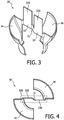
- FIG. 3 schematically depicts a perspective view
- FIG. 4 schematically depicts a top view of a non-limiting example of a heat dissipating member 30 for use in a lighting device of the present invention.
- the heat dissipating member 30 comprises a bridging member 300 including at least part of a first portion 32 and a second portion 33 that is axially displaced respective to the first portion 32.
- the bridging member 300 has a stepped shape in which an intermediate portion 31 interconnects at least a part of the first portion 32 to at least a part of the second portion 33 and axially displaces the first portion 32 respective to the second portion 33 to obtain the stepped shape.
- the intermediate portion 31 is typically located in the recess 18 of the carrier 10 and rests on the upper portion of the main body 12 of the carrier 10.
- the intermediate portion 31 is shown to have a curved shape by way of non-limiting example only.
- the intermediate portion 31 may have any suitable shape that can achieve the stepped profile of the bridging member 300; e.g. a z-shape or the like.
- the first portion 32 is thermally coupled to the second main surface 144 of the first protrusion 14 and acts as a heat sink for this part of the carrier 10.
- the second portion 33 is thermally coupled to the third main surface 162 of the second protrusion 16 and acts as a heat sink for this part of the carrier 10.
- the heat generated by the SSL elements 20 on the first main surface 142 of the first protrusion 14 will be transferred via the second main surface 144 to the first portion 32 and the heat generated by the SSL elements 20 on the second main surface 164 of the second protrusion 16 will be transferred via the first main surface 162 to the second portion 33.
- the heat dissipating member 30 further comprises a first heat dissipating portion 34 connected to the first portion 32 of the bridging member 300 for primarily dissipating the heat collected by the first portion 32 and a second heat dissipating portion 36 connected to the second portion 33 of the bridging member 300 for primarily dissipating the heat collected by the second portion 33.
- first heat dissipating portion 34 and the second heat dissipating portion 36 may have any suitable form, it is preferred that the first heat dissipating portion 34 and the second heat dissipating portion 36 match the shape of the housing of the lighting device, as will be explained in more detail later.
- the respective areas of the first heat dissipating portion 34 and the second heat dissipating portion 36 preferably are made as large as possible to maximize the heat dissipation by the first heat dissipating portion 34 and the second heat dissipating portion 36.
- the first portion 32 further comprises a first further protrusion 320 extending from the bridging member 300 and being thermally coupled to the second main surface 144 of the first protrusion 14 and the second portion 33 further comprises a second further protrusion 330 extending from the bridging member 300 and being thermally coupled to the third main surface 162 of the second protrusion 16.
- the further protrusions 320 and 330 may be used to increase or even maximize the thermal coupling between the heat dissipating member 30 and the carrier 10, thereby ensuring efficient cooling of the carrier 10 by the heat dissipating member 30.
- the one or more driver circuits 22 are located on or in the vicinity of one of the first main surface 142 and the fourth main surface 164 to ensure that the heat generated by the one or more driver circuits 22 is effectively transferred to the heat dissipating member 30 via the thermal coupling between the second main surface 144 and the first portion 32 and the third main surface 162 and the third portion 33 respectively, which first portion 32 may include the first further protrusion 320 and which second portion 33 may include the second further protrusion 330.
- the heat dissipating member 30 may be manufactured in any suitable manner, but preferably is manufactured from a single sheet of metal, e.g. by cutting, folding, bending and otherwise deforming the sheet of metal into the desired shape. Any suitable sheet metal may be used although aluminium is particularly suitable because of its low cost and pliability.
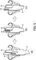
- the carrier 10 and the heat dissipating member 30 may be assembled as shown in FIG. 5 .
- step (a) the intermediate portion 31 of the bridging member 300 is inserted into the recess 18 such that the first portion 32 and the second portion 33 of the bridging member 300 are oriented more or less perpendicularly to the first protrusion 14 and the second protrusion 16 of the carrier 10.
- FIG. 6 schematically depicts a deconstructed model of a lighting device 100 according to an embodiment of the present invention.
- the lighting device 100 comprises a housing 50 into which the carrier 10 is fitted such that the one or more driver circuits 22 are electrically coupled to the conductive terminals (not shown) of the housing 50.
- the heat dissipating member 30 is engaged with the carrier 10 as previously explained.
- the carrier 10 is aligned with the principal axis of symmetry of the lighting device 100, e.g. is oriented vertically in the lighting device 100 when its principal axis is in a vertical orientation, such that the first protrusion 14 and the second protrusion 16 extend in a direction in parallel with this principal axis.
- the lighting device 100 further comprises an exit window 60, which may be transparent or translucent, and may be made of any suitable material, e.g. glass or plastics.
- the exit window 60 typically engages with the housing 50 such that the internal volume of the lighting device 100 is delimited by the inner surfaces of the housing 50 and the exit window 60 respectively.
- the lighting device 100 may further comprise a reflector 70 to shape the luminous output of the one or more SSL elements 20, e.g. LEDs, on the carrier 10.
- SSL elements 20 are only visible on the first main surface 142 of the first protrusion 14, but it should be understood that the lighting device 100 may further comprise one or more SSL elements 20, e.g. LEDs, on the fourth main surface 164 of the second protrusion 16, which is not visible in FIG. 6 .
- the reflector 70 may be mounted in any suitable manner in the lighting device 100.
- the reflector 70 may be mounted on the protrusions 14, 16 of the carrier 10.
- the reflector 70 is shaped such that it creates a luminous output distribution of the lighting device 100 that is compliant with the Energy Star ® requirements, although it should be understood that alternative embodiments in which such compliance is not achieved are also feasible.
- the lighting device 100 may comprise the same colour or different colour SSL elements.
- white light SSL elements having different colour temperatures are also considered different coloured SSL elements 20.
- the colours of the of SSL elements 20 on the first main surface 142 may be the same or may be different to each other.
- the colours of the of SSL elements 20 on the fourth main surface 164 may be the same or may be different to each other.
- the colours of the SSL elements 20 on the first main surface 142 may be the same as may be different to the colours of the SSL elements 20 on the fourth main surface 164.
- the first heat dissipating portion 34 and the second heat dissipating portion 36 match the shape of the housing of the lighting device, as is shown in Fig. 6 .
- the plastic housing 50 is moulded such that the heat dissipating member 30 is moulded into the housing 50.
- the first heat dissipating portion 34 and the second heat dissipating portion 36 of the heat dissipating member 30 are thermally coupled to the housing 50 such that the heat generated in particular by the SSL elements 20 can be effectively transferred to the housing 50, with the air surrounding the housing 50 providing further dissipation of this heat.
- the first heat dissipating portion 34 and the second heat dissipating portion 36 of the heat dissipating member 30 are in physical contact with the inner surface of the housing 50.
- the lighting device 100 may be advantageously included in a luminaire such as a holder of the lighting device, e.g. a ceiling light fitting, or an apparatus into which the lighting device is integrated, e.g. a cooker hood or the like.
- a luminaire such as a holder of the lighting device, e.g. a ceiling light fitting, or an apparatus into which the lighting device is integrated, e.g. a cooker hood or the like.
Description
- The present invention relates to a lighting device and a luminaire comprising such a lighting device.
- With a continuously growing population, it is becoming increasingly difficult to meet the world's energy needs as well as to control carbon emissions to kerb greenhouse gas emissions that are considered responsible for global warming phenomena. These concerns have triggered a drive towards more efficient energy consumption in an attempt to reduce energy consumption.
- One such area of concern is lighting applications, either in domestic or commercial settings. There is a clear trend towards the replacement of energy inefficient incandescent light bulbs with more energy-efficient replacements. Indeed, in many jurisdictions the production and retailing of incandescent light bulbs has been outlawed, thus forcing consumers to buy energy-efficient alternatives, e.g. when replacing incandescent light bulbs. For example, the US government has initiated its Energy Star® programme, which includes a list of approved replacements of incandescent light bulbs such as compact fluorescent lamps and solid state lighting (SSL) devices, e.g. light emitting diode (LED)-based light bulbs.
- It is generally recognized that SSL devices provide a particularly promising alternative due to their green credentials such as lifetime and energy consumption. SSL devices can produce a unit luminous output at a fraction of the energy cost of incandescent light bulbs. However, the commercial challenge with providing lighting devices based on SSL elements is to produce the lighting device at a cost point that makes the device accessible to large consumer volumes, as also recognized in the aforementioned Energy Star® programme. This is a far from trivial exercise. A typical SSL-based lighting device such as a light bulb contains several discrete components, such as a carrier for the one or more SSL elements, a carrier for the one or more SSL element driver circuits, a heat dissipating member to provide effective cooling to the electronic components on the various carriers, a reflector, beam shaping optics and so on, which makes the lighting device relatively complex and therefore costly.
- Although it is technically straightforward to combine some of these components, e.g. a carrier such as a printed circuit board carrying both the SSL elements and the driver circuits, the impracticalities of such design choices cannot be easily overcome. For instance, the heat flux from a carrier on which both SSL elements and driver circuits are combined is such that this heat cannot be effectively dissipated by a heat dissipating member, e.g. a heat sink, thus causing overheating of the lighting device. For this reason, separate carriers are commonly used to delocalize the heat generation in the lighting device, despite the fact that this increases its manufacturing cost.
-
US 2012/0268936 A1 discloses a lighting element comprising plural heat sink regions on respective regions of a flexible circuit board, and plural light emitters on respective regions of the flexible circuit board. This however is a complex device that cannot be manufactured in a cost-effective manner. -
US 2012/032577 discloses an LED lighting device having a cap, a circuit board assembly and a bulb envelope. The circuit board assembly is electrically mounted on the cap and has multiple circuit boards intersecting to each other to form a light frame with a criss-cross section, wherein multiple LEDs are mounted on the circuit boards. The intersecting circuit boards constitute a light frame that provides a large surface area for mounting a large number of LEDs. - The present invention seeks to provide a lighting device that can be manufactured in a more cost-effective manner.
- The present invention further seeks to provide a luminaire including such a lighting device.
- According to an aspect of the present invention, there is provided a lighting device comprising a carrier having a main body and first and second protrusions extending from said main body in the same plane of the main body, the first protrusion comprising a first main surface and an opposite second main surface, the second protrusion comprising a third main surface and an opposite fourth main surface, wherein the first main surface and the third main surface are on the same side of the carrier, said carrier carrying at least one solid state lighting element on at least one of the first main surface and the fourth main surface; and a heat dissipating member having a first portion thermally coupled to the second main surface and having a second portion thermally coupled to the third main surface, wherein the second main surface of the first protrusion is disposed on the first portion of the heat dissipating member, and the third main surface of the second protrusion is disposed on the second portion of the heat dissipating member.
- Such a lighting device benefits from the presence of a single carrier onto which the one or more SSL elements, e.g. LEDs are mounted, thereby reducing the cost of the lighting device whilst at the same time providing effective dissipation of the heat generated by the one or more SSL elements due to the fact that the heat dissipating member is thermally coupled to multiple surfaces of the carrier that do not carry any components or at least not carry SSL elements. Preferably, the at least one driver circuit is also mounted on the carrier, thereby further reducing the complexity and cost of the lighting device.
- In an embodiment, said first portion is coupled to the second main surface and said second portion is thermally coupled to the third main surface via respective bonding members. Such bonding members, e.g. PTFE or silicone gel bonding members securely fit the carrier to the heat dissipating member whilst simultaneously providing electrical insulation between the carrier and the heat dissipating member.
- The lighting device of claim may further comprise a housing and an exit window fitted to said housing, wherein said first and second protrusions extend in a direction in parallel with a main axis of the lighting device, said main axis extending through the housing and the exit window.
- In other words, in this preferred embodiment, the carrier, e.g. a printed circuit board, is mounted vertically in the lighting device, which is an area-efficient manner of integrating the carrier in the lighting device.
- In an embodiment, the heat dissipating member comprises a first heat dissipating portion; a second heat dissipating portion opposite the first heat dissipating portion; a bridging member comprising at least a part of the first portion and the second portion, said bridging member connecting the first heat dissipating portion to the second heat dissipating portion. In this embodiment, the bridging member thermally couples the first and second heat dissipating portions to respective protrusions of the carrier, such that a large area heat dissipating member is provided that can effectively dissipate the heat generated by the one or more SSL elements and driver circuits.
- The shape of the first and second heat dissipating portions may match the shape of the housing to ensure a good fit of the heat dissipating member in the housing.
- In an embodiment, the first portion further comprises a first further protrusion extending from the bridging member and being thermally coupled to the second main surface; and the second portion further comprises a second further protrusion extending from the bridging member and being thermally coupled to the third main surface. This ensures a particularly good heat transfer from the carrier to the heat dissipating member.
- The lighting device preferably comprises a plurality of solid state lighting elements on at least one of the first main surface and the fourth main surface. The solid state lighting elements preferably are distributed over both the first main surface and the fourth main surface to increase the distribution of the luminous output of the lighting device. It has been found that in this embodiment a lighting device can be produced that is compliant with the Energy Star® requirements, especially when the lighting device further comprises a reflector to further increase the luminous distribution, i.e. to make the luminous distribution less directional. Such a reflector may for instance be mounted on the carrier.
- The heat dissipating member preferably is formed from a single sheet of metal to provide a low-cost heat dissipating member. Aluminium is particularly preferred as the metal because it is cheap and easily pliable.
- The lighting device may be a light bulb.
- In accordance with another aspect of the present invention, there is provided a luminaire comprising the lighting device according to an embodiment of the present invention. Such a luminaire may for instance be a holder of the lighting device or an apparatus into which the lighting device is integrated.
- Embodiments of the invention are described in more detail and by way of non-limiting examples with reference to the accompanying drawings, wherein:
-
FIG. 1 schematically depicts an aspect of a lighting device according to an embodiment of the present invention; -
FIG. 2 schematically depicts another aspect of a lighting device according to an embodiment of the present invention; -
FIG. 3 schematically depicts yet another aspect of a lighting device according to an embodiment of the present invention; -
FIG. 4 schematically depicts yet another aspect of a lighting device according to an embodiment of the present invention; -
FIG. 5 schematically depicts a method of assembling part of a lighting device according to an embodiment of the present invention; and -
FIG. 6 schematically depicts a lighting device according to an embodiment of the present invention. - It should be understood that the Figures are merely schematic and are not drawn to scale. It should also be understood that the same reference numerals are used throughout the Figures to indicate the same or similar parts.
-
FIG. 1 and 2 respectively schematically depict a side view and a top view of acarrier 10 that forms part of the lighting device of the present invention. Thecarrier 10, which may be a printed circuit board, comprises amain body 12. Afirst protrusion 14 and asecond protrusion 16 extend in parallel from themain body 10, thereby forming arecess 18 that is delimited by themain body 10, thefirst protrusion 14 and thesecond protrusion 16. In other words, thefirst protrusion 14 and thesecond protrusion 16 extend from themain body 12 in the plane of themain body 12. It is noted for the avoidance of doubt that the dashed boxes inFIG. 1 are merely identify the various portions of thecarrier 10 and are not to be construed as somehow delimiting thecarrier 10. - The
first protrusion 14 has a firstmain surface 142 onto which one ormore SSL elements 20 may be mounted in any suitable manner, e.g. by soldering. InFIG. 1 , threeSSL elements 20 are shown by way of non-limiting example only; it should be understood that the firstmain surface 142 may carry any suitable number ofSSL elements 20, e.g. one ormore SSL elements 20. Thefirst protrusion 14 further has a secondmain surface 144 opposite the firstmain surface 142 for thermally coupling thecarrier 10 to a first portion of aheat dissipating member 30, as will be explained in more detail later. It is noted that theheat dissipating member 30 is not shown inFIG. 1 for the sake of clarity only. - The
second protrusion 16 has a fourthmain surface 164 onto which one ormore SSL elements 20 may be mounted. It should be understood that the fourthmain surface 164 may carry any suitable number ofSSL elements 20, e.g. one ormore SSL elements 20, or noSSL elements 20 at all although the latter is not preferred. Thesecond protrusion 16 further has a thirdmain surface 162 opposite the fourthmain surface 164 for thermally coupling thecarrier 10 to a second portion of aheat dissipating member 30, as will be explained in more detail later. The first and thirdmain surfaces carrier 10. The second and fourthmain surfaces carrier 10. - The lighting device may further comprise a
first bonding member 40 between the secondmain surface 144 andheat dissipating member 30 and asecond bonding member 40 between the thirdmain surface 162 and theheat dissipating member 30 for securing theheat dissipating member 30 to thecarrier 10. Thebonding members 40 preferably are of an electrically insulating material to electrically insulate theheat dissipating member 30 from thecarrier 10. Thebonding members 40 should have good heat conductive properties to establish a sufficient thermal coupling between theheat dissipating member 30 and thecarrier 10. Non-limiting examples of suitable electrically insulating materials include polytetrafluoroethylene (PTFE) and silicone gel. - In an embodiment, the
carrier 10 further comprises at least onedriver circuit 22 for driving theSSL elements 20. The at least onedriver circuit 22 may be located on any suitable part of thecarrier 10. InFIG. 1 , thedriver circuit 22 is shown on themain body 12 of thecarrier 10 by way of non-limiting example only. Alternatively, thedriver circuit 22 may be located on the firstmain surface 142 or on the fourthmain surface 164. More than onedriver circuit 22 may be present on thecarrier 10. For instance, a further driver circuit may be located on the other side of themain body 12. It should however be understood that it is not essential that the at least onedriver circuit 22 is mounted on thecarrier 10. Instead, the at least onedriver circuit 22 may be provided on a separate carrier (not shown), in which case thecarrier 10 will include wiring and a terminal for connecting the at least onedriver circuit 22 to theSSL elements 20. - As can be seen in
FIG. 2 , theheat dissipating member 30 has a twisted structure such that a first portion of theheat dissipating member 30 is thermally coupled to the secondmain surface 144 of thefirst protrusion 14 and a second portion of theheat dissipating member 30 is thermally coupled to the thirdmain surface 162 of thesecond protrusion 16. In the context of the present invention, the term 'thermally coupled' should be interpreted to mean two bodies in direct or indirect physical contact with each other, e.g. coupled to each other via a thermally conducting body, or at least located in close enough vicinity to each other to allow heat to be effectively transferred from thecarrier 10 to theheat dissipating member 30. -
FIG. 3 schematically depicts a perspective view andFIG. 4 schematically depicts a top view of a non-limiting example of aheat dissipating member 30 for use in a lighting device of the present invention. Theheat dissipating member 30 comprises a bridgingmember 300 including at least part of afirst portion 32 and asecond portion 33 that is axially displaced respective to thefirst portion 32. In other words, the bridgingmember 300 has a stepped shape in which anintermediate portion 31 interconnects at least a part of thefirst portion 32 to at least a part of thesecond portion 33 and axially displaces thefirst portion 32 respective to thesecond portion 33 to obtain the stepped shape. Theintermediate portion 31 is typically located in therecess 18 of thecarrier 10 and rests on the upper portion of themain body 12 of thecarrier 10. InFIG. 3 and 4 , theintermediate portion 31 is shown to have a curved shape by way of non-limiting example only. Theintermediate portion 31 may have any suitable shape that can achieve the stepped profile of the bridgingmember 300; e.g. a z-shape or the like. - The
first portion 32 is thermally coupled to the secondmain surface 144 of thefirst protrusion 14 and acts as a heat sink for this part of thecarrier 10. Thesecond portion 33 is thermally coupled to the thirdmain surface 162 of thesecond protrusion 16 and acts as a heat sink for this part of thecarrier 10. In other words, the heat generated by theSSL elements 20 on the firstmain surface 142 of thefirst protrusion 14 will be transferred via the secondmain surface 144 to thefirst portion 32 and the heat generated by theSSL elements 20 on the secondmain surface 164 of thesecond protrusion 16 will be transferred via the firstmain surface 162 to thesecond portion 33. - The
heat dissipating member 30 further comprises a firstheat dissipating portion 34 connected to thefirst portion 32 of the bridgingmember 300 for primarily dissipating the heat collected by thefirst portion 32 and a secondheat dissipating portion 36 connected to thesecond portion 33 of the bridgingmember 300 for primarily dissipating the heat collected by thesecond portion 33. Although the firstheat dissipating portion 34 and the secondheat dissipating portion 36 may have any suitable form, it is preferred that the firstheat dissipating portion 34 and the secondheat dissipating portion 36 match the shape of the housing of the lighting device, as will be explained in more detail later. As will be understood by the skilled person, the respective areas of the firstheat dissipating portion 34 and the secondheat dissipating portion 36 preferably are made as large as possible to maximize the heat dissipation by the firstheat dissipating portion 34 and the secondheat dissipating portion 36. - In an embodiment, the
first portion 32 further comprises a firstfurther protrusion 320 extending from the bridgingmember 300 and being thermally coupled to the secondmain surface 144 of thefirst protrusion 14 and thesecond portion 33 further comprises a secondfurther protrusion 330 extending from the bridgingmember 300 and being thermally coupled to the thirdmain surface 162 of thesecond protrusion 16. - The
further protrusions heat dissipating member 30 and thecarrier 10, thereby ensuring efficient cooling of thecarrier 10 by theheat dissipating member 30. For this reason, it is preferable that the one ormore driver circuits 22 are located on or in the vicinity of one of the firstmain surface 142 and the fourthmain surface 164 to ensure that the heat generated by the one ormore driver circuits 22 is effectively transferred to theheat dissipating member 30 via the thermal coupling between the secondmain surface 144 and thefirst portion 32 and the thirdmain surface 162 and thethird portion 33 respectively, whichfirst portion 32 may include the firstfurther protrusion 320 and whichsecond portion 33 may include the secondfurther protrusion 330. - The
heat dissipating member 30 may be manufactured in any suitable manner, but preferably is manufactured from a single sheet of metal, e.g. by cutting, folding, bending and otherwise deforming the sheet of metal into the desired shape. Any suitable sheet metal may be used although aluminium is particularly suitable because of its low cost and pliability. - The
carrier 10 and theheat dissipating member 30 may be assembled as shown inFIG. 5 . In step (a), theintermediate portion 31 of the bridgingmember 300 is inserted into therecess 18 such that thefirst portion 32 and thesecond portion 33 of the bridgingmember 300 are oriented more or less perpendicularly to thefirst protrusion 14 and thesecond protrusion 16 of thecarrier 10. - Upon completion of the insertion process as shown in step (b), when the
intermediate portion 31 of the bridgingmember 300 comes to rest on themain body 12 of thecarrier 10, theheat dissipating member 30 is twisted relative to thecarrier 10 to arrive at the assembly shown in step (c), in which thefirst portion 32 of the bridgingmember 300 faces the secondmain surface 144 of thefirst protrusion 14 and is thermally coupled thereto and in which thesecond portion 33 of the bridgingmember 300 faces the thirdmain surface 162 of thesecond protrusion 16 and is thermally coupled thereto.
FIG. 6 schematically depicts a deconstructed model of alighting device 100 according to an embodiment of the present invention. Thelighting device 100 comprises ahousing 50 into which thecarrier 10 is fitted such that the one ormore driver circuits 22 are electrically coupled to the conductive terminals (not shown) of thehousing 50. Theheat dissipating member 30 is engaged with thecarrier 10 as previously explained. In other words, thecarrier 10 is aligned with the principal axis of symmetry of thelighting device 100, e.g. is oriented vertically in thelighting device 100 when its principal axis is in a vertical orientation, such that thefirst protrusion 14 and thesecond protrusion 16 extend in a direction in parallel with this principal axis. - The
lighting device 100 further comprises anexit window 60, which may be transparent or translucent, and may be made of any suitable material, e.g. glass or plastics. Theexit window 60 typically engages with thehousing 50 such that the internal volume of thelighting device 100 is delimited by the inner surfaces of thehousing 50 and theexit window 60 respectively. - The
lighting device 100 may further comprise areflector 70 to shape the luminous output of the one ormore SSL elements 20, e.g. LEDs, on thecarrier 10. InFIG. 6 ,SSL elements 20 are only visible on the firstmain surface 142 of thefirst protrusion 14, but it should be understood that thelighting device 100 may further comprise one ormore SSL elements 20, e.g. LEDs, on the fourthmain surface 164 of thesecond protrusion 16, which is not visible inFIG. 6 . Thereflector 70 may be mounted in any suitable manner in thelighting device 100. For instance, thereflector 70 may be mounted on theprotrusions carrier 10. In an embodiment, thereflector 70 is shaped such that it creates a luminous output distribution of thelighting device 100 that is compliant with the Energy Star® requirements, although it should be understood that alternative embodiments in which such compliance is not achieved are also feasible. - The
lighting device 100 may comprise the same colour or different colour SSL elements. In this context, white light SSL elements having different colour temperatures are also considered differentcoloured SSL elements 20. For instance, the colours of the ofSSL elements 20 on the firstmain surface 142 may be the same or may be different to each other. The colours of the ofSSL elements 20 on the fourthmain surface 164 may be the same or may be different to each other. The colours of theSSL elements 20 on the firstmain surface 142 may be the same as may be different to the colours of theSSL elements 20 on the fourthmain surface 164. - In order to obtain a good fit of the assembly formed by the
carrier 10 and theheat dissipating member 30 in thehousing 50, the firstheat dissipating portion 34 and the secondheat dissipating portion 36 match the shape of the housing of the lighting device, as is shown inFig. 6 . In a particularly advantageous embodiment, theplastic housing 50 is moulded such that theheat dissipating member 30 is moulded into thehousing 50. The firstheat dissipating portion 34 and the secondheat dissipating portion 36 of theheat dissipating member 30 are thermally coupled to thehousing 50 such that the heat generated in particular by theSSL elements 20 can be effectively transferred to thehousing 50, with the air surrounding thehousing 50 providing further dissipation of this heat. Preferably, the firstheat dissipating portion 34 and the secondheat dissipating portion 36 of theheat dissipating member 30 are in physical contact with the inner surface of thehousing 50. - The
lighting device 100 according to embodiments of the present invention may be advantageously included in a luminaire such as a holder of the lighting device, e.g. a ceiling light fitting, or an apparatus into which the lighting device is integrated, e.g. a cooker hood or the like. - It should be noted that the above-mentioned embodiments illustrate rather than limit the invention, and that those skilled in the art will be able to design many alternative embodiments without departing from the scope of the appended claims. In the claims, any reference signs placed between parentheses shall not be construed as limiting the claim. The word "comprising" does not exclude the presence of elements or steps other than those listed in a claim. The word "a" or "an" preceding an element does not exclude the presence of a plurality of such elements. The invention can be implemented by means of hardware comprising several distinct elements. In the device claim enumerating several means, several of these means can be embodied by one and the same item of hardware. The mere fact that certain measures are recited in mutually different dependent claims does not indicate that a combination of these measures cannot be used to advantage.
Claims (15)
- A lighting device (100) comprising:a carrier (10) having a main body (12) and first and second protrusions (14, 16) extending from said main body (12) in the same plane of the main body (12), the first protrusion comprising a first main surface (142) and an opposite second main surface (144), the second protrusion comprising a third main surface (162) and an opposite fourth main surface (164), wherein the first main surface and the third main surface are on the same side of the carrier, said carrier carrying at least one solid state lighting element (20) on the first main surface, and at least one solid state lighting element (20) on the fourth main surface; anda heat dissipating member (30) having a first portion (32) thermally coupled to the second main surface and having a second portion (33) thermally coupled to the third main surface,characterized in that the second main surface (144) of the first protrusion (14) is disposed on the first portion (32) of the heat dissipating member (30), and the third main surface (162) of the second protrusion (16) is disposed on the second portion (33) of the heat dissipating member (30).
- The lighting device (100) of claim 1, said first portion (32) is coupled to the second main surface (144) and said second portion (33) is thermally coupled to the third main surface (162) via respective bonding members (40).
- The lighting device (100) of claim 1 or 2, further comprising at least one driver circuit (22) on the carrier (10).
- The lighting device (100) of any of claims 1-3, further comprising a housing (50) and an exit window (60) fitted to said housing, wherein said first and second protrusions (14, 16) extend in a direction in parallel with a main axis of the lighting device, said main axis extending through the housing and the exit window.
- The lighting device (100) of any of claims 1-4, wherein the heat dissipating member (30) comprises:a first heat dissipating portion (34);a second heat dissipating portion (36) opposite the first heat dissipating portion; anda bridging member (300) comprising at least a part of the first portion (32) and the second portion (33), said bridging member connecting the first heat dissipating portion to the second heat dissipating portion.
- The lighting device (100) of claim 5, wherein the first and second heat dissipating bodies (34, 36) match the shape of the housing (50).
- The lighting device (100) of claim 5 or 6, wherein:the first portion (32) further comprises a first further protrusion (320) extending from the bridging member (300) and being thermally coupled to the second main surface (144); andthe second portion (33) further comprises a second further protrusion (330) extending from the bridging member and being thermally coupled to the third main surface (162).
- The lighting device (100) of any of claims 1-7, wherein the lighting device comprises a plurality of solid state lighting elements (20) on at least one of the first main surface (142) and the fourth main surface (164).
- The lighting device (100) of claim 8, wherein the plurality of solid state lighting elements (20) are distributed over the first main surface (142) and the fourth main surface (164).
- The lighting device (100) of any of claims 1-9, further comprising a reflector (70) mounted on the carrier (10).
- The lighting device (100) of any of claims 1-10, wherein the heat dissipating member (30) is formed from a single sheet of metal.
- The lighting device (100) of claim 11, wherein the metal is aluminium.
- The lighting device (100) of any of claims 1-12, wherein the lighting device is a light bulb.
- The lighting device (100) of any of claims 1-13, wherein the at least one solid state lighting element (20) is a light emitting diode.
- A luminaire comprising the lighting device (100) of any of claims 1-14.
Applications Claiming Priority (2)
| Application Number | Priority Date | Filing Date | Title |
|---|---|---|---|
| CNPCT/CN2013/074027 | 2013-04-10 | ||
| PCT/IB2014/060495 WO2014167480A1 (en) | 2013-04-10 | 2014-04-07 | Lighting device and luminaire |
Publications (2)
| Publication Number | Publication Date |
|---|---|
| EP2986903A1 EP2986903A1 (en) | 2016-02-24 |
| EP2986903B1 true EP2986903B1 (en) | 2017-09-13 |
Family
ID=50628874
Family Applications (1)
| Application Number | Title | Priority Date | Filing Date |
|---|---|---|---|
| EP14720708.8A Active EP2986903B1 (en) | 2013-04-10 | 2014-04-07 | Lighting device and luminaire |
Country Status (6)
| Country | Link |
|---|---|
| US (1) | US9920915B2 (en) |
| EP (1) | EP2986903B1 (en) |
| JP (1) | JP6433979B2 (en) |
| BR (1) | BR112015025603A2 (en) |
| RU (1) | RU2644109C2 (en) |
| WO (1) | WO2014167480A1 (en) |
Families Citing this family (4)
| Publication number | Priority date | Publication date | Assignee | Title |
|---|---|---|---|---|
| DE102015206802A1 (en) * | 2015-04-15 | 2016-10-20 | Osram Gmbh | Lamp with LEDs |
| DE102015206797A1 (en) | 2015-04-15 | 2016-10-20 | Osram Gmbh | Lamp with LEDs |
| TWI746767B (en) * | 2017-01-17 | 2021-11-21 | 晶元光電股份有限公司 | Led bulb |
| WO2019197289A1 (en) | 2018-04-10 | 2019-10-17 | Signify Holding B.V. | Decorative light source shielding |
Citations (1)
| Publication number | Priority date | Publication date | Assignee | Title |
|---|---|---|---|---|
| US20120032577A1 (en) * | 2010-08-05 | 2012-02-09 | David Huang | Led lighting device |
Family Cites Families (22)
| Publication number | Priority date | Publication date | Assignee | Title |
|---|---|---|---|---|
| US8093823B1 (en) * | 2000-02-11 | 2012-01-10 | Altair Engineering, Inc. | Light sources incorporating light emitting diodes |
| JP3716252B2 (en) | 2002-12-26 | 2005-11-16 | ローム株式会社 | Light emitting device and lighting device |
| JP2009080966A (en) | 2007-09-25 | 2009-04-16 | Toshiba Lighting & Technology Corp | Illumination device |
| US8018136B2 (en) | 2008-02-28 | 2011-09-13 | Tyco Electronics Corporation | Integrated LED driver for LED socket |
| US8013501B2 (en) * | 2008-06-04 | 2011-09-06 | Forever Bulb, Llc | LED-based light bulb device |
| CN101614383A (en) * | 2008-06-27 | 2009-12-30 | 富准精密工业(深圳)有限公司 | LED lamp |
| JP2010055993A (en) * | 2008-08-29 | 2010-03-11 | Toshiba Lighting & Technology Corp | Lighting system and luminaire |
| JP2010135309A (en) | 2008-11-06 | 2010-06-17 | Rohm Co Ltd | Led lamp |
| CN101655187B (en) * | 2008-12-17 | 2011-11-23 | 马士科技有限公司 | LED reflector lamp |
| WO2010136950A1 (en) | 2009-05-28 | 2010-12-02 | Koninklijke Philips Electronics N.V. | Illumination device and method for assembly of an illumination device |
| CN102032480B (en) * | 2009-09-25 | 2013-07-31 | 东芝照明技术株式会社 | Self-ballasted lamp and lighting equipment |
| US8536807B2 (en) * | 2010-01-04 | 2013-09-17 | Dongguan Hexi Optical Electric Technology Co., Ltd. | LED bulb |
| US8596821B2 (en) * | 2010-06-08 | 2013-12-03 | Cree, Inc. | LED light bulbs |
| RU2607531C2 (en) * | 2011-01-11 | 2017-01-10 | Конинклейке Филипс Н.В. | Lighting fixture |
| US8410726B2 (en) * | 2011-02-22 | 2013-04-02 | Quarkstar Llc | Solid state lamp using modular light emitting elements |
| US8272766B2 (en) * | 2011-03-18 | 2012-09-25 | Abl Ip Holding Llc | Semiconductor lamp with thermal handling system |
| US10030863B2 (en) | 2011-04-19 | 2018-07-24 | Cree, Inc. | Heat sink structures, lighting elements and lamps incorporating same, and methods of making same |
| US8283877B2 (en) * | 2011-06-07 | 2012-10-09 | Switch Bulb Company, Inc. | Thermal protection circuit for an LED bulb |
| JP5738713B2 (en) * | 2011-08-05 | 2015-06-24 | 三菱電機照明株式会社 | Lighting device |
| WO2013040506A1 (en) * | 2011-09-15 | 2013-03-21 | Switch Bulb Company, Inc. | Led packages for an led bulb |
| JP6192655B2 (en) * | 2011-11-23 | 2017-09-06 | スリーエム イノベイティブ プロパティズ カンパニー | Flexible light-emitting semiconductor device having a three-dimensional structure |
| US20130163235A1 (en) * | 2011-12-21 | 2013-06-27 | Ukin Technology Co., Ltd | Led lamp capable of multilateral connection |
-
2014
- 2014-04-07 JP JP2016507089A patent/JP6433979B2/en active Active
- 2014-04-07 US US14/784,067 patent/US9920915B2/en active Active
- 2014-04-07 RU RU2015148153A patent/RU2644109C2/en active
- 2014-04-07 EP EP14720708.8A patent/EP2986903B1/en active Active
- 2014-04-07 BR BR112015025603A patent/BR112015025603A2/en not_active IP Right Cessation
- 2014-04-07 WO PCT/IB2014/060495 patent/WO2014167480A1/en active Application Filing
Patent Citations (1)
| Publication number | Priority date | Publication date | Assignee | Title |
|---|---|---|---|---|
| US20120032577A1 (en) * | 2010-08-05 | 2012-02-09 | David Huang | Led lighting device |
Also Published As
| Publication number | Publication date |
|---|---|
| EP2986903A1 (en) | 2016-02-24 |
| US20160061388A1 (en) | 2016-03-03 |
| WO2014167480A1 (en) | 2014-10-16 |
| BR112015025603A2 (en) | 2017-07-18 |
| RU2015148153A (en) | 2017-05-12 |
| JP2016518684A (en) | 2016-06-23 |
| RU2644109C2 (en) | 2018-02-07 |
| US9920915B2 (en) | 2018-03-20 |
| JP6433979B2 (en) | 2018-12-05 |
Similar Documents
| Publication | Publication Date | Title |
|---|---|---|
| JP5795632B2 (en) | LED bulb | |
| US10436392B2 (en) | LED filament light | |
| US20120243230A1 (en) | Heat transfer assembly for led-based light bulb or lamp device | |
| JP6356211B2 (en) | LED lighting device and manufacturing method thereof | |
| US8317372B2 (en) | LED bulb | |
| CN107388062A (en) | Bulb device and the method for making lighting device | |
| US20110001417A1 (en) | LED bulb with heat removal device | |
| EP2986903B1 (en) | Lighting device and luminaire | |
| EP2728250B1 (en) | Apparatus, method and system for a modular light-emitting diode circuit assembly | |
| US20200056748A1 (en) | Led bulb | |
| US20160025276A1 (en) | Light emitting diode spotlight | |
| US10935189B2 (en) | LED light bulb | |
| JP5718199B2 (en) | Light bulb-type lighting device | |
| US10634286B2 (en) | Lighting device and manufacturing method thereof | |
| US20140016324A1 (en) | Illuminant device | |
| EP2917641B1 (en) | Lighting device | |
| JP2016025088A (en) | Light-emitting diode bulb | |
| CN201739867U (en) | Electrothermal separation LED lamp-bulb modular structure | |
| CN105143761B (en) | Lighting apparatus and light fixture | |
| CN102374410B (en) | LED (light emitting diode) bulb device | |
| US8864339B2 (en) | Thermal solution for LED candelabra lamps | |
| GB2499782A (en) | LED lamp having shell structure | |
| GB2499783A (en) | LED lamp having shell structure | |
| TW201135139A (en) | LED lamp, LED module and heat sink thereof |
Legal Events
| Date | Code | Title | Description |
|---|---|---|---|
| PUAI | Public reference made under article 153(3) epc to a published international application that has entered the european phase |
Free format text: ORIGINAL CODE: 0009012 |
|
| 17P | Request for examination filed |
Effective date: 20151110 |
|
| AK | Designated contracting states |
Kind code of ref document: A1 Designated state(s): AL AT BE BG CH CY CZ DE DK EE ES FI FR GB GR HR HU IE IS IT LI LT LU LV MC MK MT NL NO PL PT RO RS SE SI SK SM TR |
|
| AX | Request for extension of the european patent |
Extension state: BA ME |
|
| DAX | Request for extension of the european patent (deleted) | ||
| 17Q | First examination report despatched |
Effective date: 20160720 |
|
| RAP1 | Party data changed (applicant data changed or rights of an application transferred) |
Owner name: PHILIPS LIGHTING HOLDING B.V. |
|
| GRAP | Despatch of communication of intention to grant a patent |
Free format text: ORIGINAL CODE: EPIDOSNIGR1 |
|
| INTG | Intention to grant announced |
Effective date: 20170406 |
|
| GRAS | Grant fee paid |
Free format text: ORIGINAL CODE: EPIDOSNIGR3 |
|
| GRAA | (expected) grant |
Free format text: ORIGINAL CODE: 0009210 |
|
| RIN1 | Information on inventor provided before grant (corrected) |
Inventor name: ZHANG, XIAO QIAO Inventor name: XIONG, YAN |
|
| AK | Designated contracting states |
Kind code of ref document: B1 Designated state(s): AL AT BE BG CH CY CZ DE DK EE ES FI FR GB GR HR HU IE IS IT LI LT LU LV MC MK MT NL NO PL PT RO RS SE SI SK SM TR |
|
| REG | Reference to a national code |
Ref country code: GB Ref legal event code: FG4D |
|
| REG | Reference to a national code |
Ref country code: CH Ref legal event code: EP |
|
| REG | Reference to a national code |
Ref country code: IE Ref legal event code: FG4D |
|
| REG | Reference to a national code |
Ref country code: AT Ref legal event code: REF Ref document number: 928522 Country of ref document: AT Kind code of ref document: T Effective date: 20171015 |
|
| REG | Reference to a national code |
Ref country code: DE Ref legal event code: R096 Ref document number: 602014014542 Country of ref document: DE |
|
| REG | Reference to a national code |
Ref country code: CH Ref legal event code: NV Representative=s name: FELBER UND PARTNER AG, CH |
|
| REG | Reference to a national code |
Ref country code: NL Ref legal event code: FP |
|
| REG | Reference to a national code |
Ref country code: SE Ref legal event code: TRGR |
|
| REG | Reference to a national code |
Ref country code: LT Ref legal event code: MG4D |
|
| PG25 | Lapsed in a contracting state [announced via postgrant information from national office to epo] |
Ref country code: LT Free format text: LAPSE BECAUSE OF FAILURE TO SUBMIT A TRANSLATION OF THE DESCRIPTION OR TO PAY THE FEE WITHIN THE PRESCRIBED TIME-LIMIT Effective date: 20170913 Ref country code: NO Free format text: LAPSE BECAUSE OF FAILURE TO SUBMIT A TRANSLATION OF THE DESCRIPTION OR TO PAY THE FEE WITHIN THE PRESCRIBED TIME-LIMIT Effective date: 20171213 Ref country code: HR Free format text: LAPSE BECAUSE OF FAILURE TO SUBMIT A TRANSLATION OF THE DESCRIPTION OR TO PAY THE FEE WITHIN THE PRESCRIBED TIME-LIMIT Effective date: 20170913 Ref country code: FI Free format text: LAPSE BECAUSE OF FAILURE TO SUBMIT A TRANSLATION OF THE DESCRIPTION OR TO PAY THE FEE WITHIN THE PRESCRIBED TIME-LIMIT Effective date: 20170913 |
|
| REG | Reference to a national code |
Ref country code: AT Ref legal event code: MK05 Ref document number: 928522 Country of ref document: AT Kind code of ref document: T Effective date: 20170913 |
|
| PG25 | Lapsed in a contracting state [announced via postgrant information from national office to epo] |
Ref country code: GR Free format text: LAPSE BECAUSE OF FAILURE TO SUBMIT A TRANSLATION OF THE DESCRIPTION OR TO PAY THE FEE WITHIN THE PRESCRIBED TIME-LIMIT Effective date: 20171214 Ref country code: BG Free format text: LAPSE BECAUSE OF FAILURE TO SUBMIT A TRANSLATION OF THE DESCRIPTION OR TO PAY THE FEE WITHIN THE PRESCRIBED TIME-LIMIT Effective date: 20171213 Ref country code: LV Free format text: LAPSE BECAUSE OF FAILURE TO SUBMIT A TRANSLATION OF THE DESCRIPTION OR TO PAY THE FEE WITHIN THE PRESCRIBED TIME-LIMIT Effective date: 20170913 Ref country code: ES Free format text: LAPSE BECAUSE OF FAILURE TO SUBMIT A TRANSLATION OF THE DESCRIPTION OR TO PAY THE FEE WITHIN THE PRESCRIBED TIME-LIMIT Effective date: 20170913 Ref country code: RS Free format text: LAPSE BECAUSE OF FAILURE TO SUBMIT A TRANSLATION OF THE DESCRIPTION OR TO PAY THE FEE WITHIN THE PRESCRIBED TIME-LIMIT Effective date: 20170913 |
|
| REG | Reference to a national code |
Ref country code: FR Ref legal event code: PLFP Year of fee payment: 5 |
|
| PG25 | Lapsed in a contracting state [announced via postgrant information from national office to epo] |
Ref country code: CZ Free format text: LAPSE BECAUSE OF FAILURE TO SUBMIT A TRANSLATION OF THE DESCRIPTION OR TO PAY THE FEE WITHIN THE PRESCRIBED TIME-LIMIT Effective date: 20170913 Ref country code: PL Free format text: LAPSE BECAUSE OF FAILURE TO SUBMIT A TRANSLATION OF THE DESCRIPTION OR TO PAY THE FEE WITHIN THE PRESCRIBED TIME-LIMIT Effective date: 20170913 Ref country code: RO Free format text: LAPSE BECAUSE OF FAILURE TO SUBMIT A TRANSLATION OF THE DESCRIPTION OR TO PAY THE FEE WITHIN THE PRESCRIBED TIME-LIMIT Effective date: 20170913 |
|
| PG25 | Lapsed in a contracting state [announced via postgrant information from national office to epo] |
Ref country code: AT Free format text: LAPSE BECAUSE OF FAILURE TO SUBMIT A TRANSLATION OF THE DESCRIPTION OR TO PAY THE FEE WITHIN THE PRESCRIBED TIME-LIMIT Effective date: 20170913 Ref country code: IS Free format text: LAPSE BECAUSE OF FAILURE TO SUBMIT A TRANSLATION OF THE DESCRIPTION OR TO PAY THE FEE WITHIN THE PRESCRIBED TIME-LIMIT Effective date: 20180113 Ref country code: SK Free format text: LAPSE BECAUSE OF FAILURE TO SUBMIT A TRANSLATION OF THE DESCRIPTION OR TO PAY THE FEE WITHIN THE PRESCRIBED TIME-LIMIT Effective date: 20170913 Ref country code: EE Free format text: LAPSE BECAUSE OF FAILURE TO SUBMIT A TRANSLATION OF THE DESCRIPTION OR TO PAY THE FEE WITHIN THE PRESCRIBED TIME-LIMIT Effective date: 20170913 Ref country code: IT Free format text: LAPSE BECAUSE OF FAILURE TO SUBMIT A TRANSLATION OF THE DESCRIPTION OR TO PAY THE FEE WITHIN THE PRESCRIBED TIME-LIMIT Effective date: 20170913 Ref country code: SM Free format text: LAPSE BECAUSE OF FAILURE TO SUBMIT A TRANSLATION OF THE DESCRIPTION OR TO PAY THE FEE WITHIN THE PRESCRIBED TIME-LIMIT Effective date: 20170913 |
|
| REG | Reference to a national code |
Ref country code: DE Ref legal event code: R097 Ref document number: 602014014542 Country of ref document: DE |
|
| PLBE | No opposition filed within time limit |
Free format text: ORIGINAL CODE: 0009261 |
|
| STAA | Information on the status of an ep patent application or granted ep patent |
Free format text: STATUS: NO OPPOSITION FILED WITHIN TIME LIMIT |
|
| PG25 | Lapsed in a contracting state [announced via postgrant information from national office to epo] |
Ref country code: DK Free format text: LAPSE BECAUSE OF FAILURE TO SUBMIT A TRANSLATION OF THE DESCRIPTION OR TO PAY THE FEE WITHIN THE PRESCRIBED TIME-LIMIT Effective date: 20170913 |
|
| 26N | No opposition filed |
Effective date: 20180614 |
|
| PG25 | Lapsed in a contracting state [announced via postgrant information from national office to epo] |
Ref country code: MC Free format text: LAPSE BECAUSE OF FAILURE TO SUBMIT A TRANSLATION OF THE DESCRIPTION OR TO PAY THE FEE WITHIN THE PRESCRIBED TIME-LIMIT Effective date: 20170913 Ref country code: SI Free format text: LAPSE BECAUSE OF FAILURE TO SUBMIT A TRANSLATION OF THE DESCRIPTION OR TO PAY THE FEE WITHIN THE PRESCRIBED TIME-LIMIT Effective date: 20170913 |
|
| REG | Reference to a national code |
Ref country code: BE Ref legal event code: MM Effective date: 20180430 |
|
| REG | Reference to a national code |
Ref country code: IE Ref legal event code: MM4A |
|
| PG25 | Lapsed in a contracting state [announced via postgrant information from national office to epo] |
Ref country code: LU Free format text: LAPSE BECAUSE OF NON-PAYMENT OF DUE FEES Effective date: 20180407 |
|
| PG25 | Lapsed in a contracting state [announced via postgrant information from national office to epo] |
Ref country code: BE Free format text: LAPSE BECAUSE OF NON-PAYMENT OF DUE FEES Effective date: 20180430 |
|
| PG25 | Lapsed in a contracting state [announced via postgrant information from national office to epo] |
Ref country code: IE Free format text: LAPSE BECAUSE OF NON-PAYMENT OF DUE FEES Effective date: 20180407 |
|
| PG25 | Lapsed in a contracting state [announced via postgrant information from national office to epo] |
Ref country code: MT Free format text: LAPSE BECAUSE OF NON-PAYMENT OF DUE FEES Effective date: 20180407 |
|
| REG | Reference to a national code |
Ref country code: NL Ref legal event code: HC Owner name: SIGNIFY HOLDING B.V.; NL Free format text: DETAILS ASSIGNMENT: CHANGE OF OWNER(S), CHANGE OF OWNER(S) NAME; FORMER OWNER NAME: PHILIPS LIGHTING HOLDING B.V. Effective date: 20200304 |
|
| PG25 | Lapsed in a contracting state [announced via postgrant information from national office to epo] |
Ref country code: TR Free format text: LAPSE BECAUSE OF FAILURE TO SUBMIT A TRANSLATION OF THE DESCRIPTION OR TO PAY THE FEE WITHIN THE PRESCRIBED TIME-LIMIT Effective date: 20170913 |
|
| PG25 | Lapsed in a contracting state [announced via postgrant information from national office to epo] |
Ref country code: PT Free format text: LAPSE BECAUSE OF FAILURE TO SUBMIT A TRANSLATION OF THE DESCRIPTION OR TO PAY THE FEE WITHIN THE PRESCRIBED TIME-LIMIT Effective date: 20170913 |
|
| PG25 | Lapsed in a contracting state [announced via postgrant information from national office to epo] |
Ref country code: MK Free format text: LAPSE BECAUSE OF NON-PAYMENT OF DUE FEES Effective date: 20170913 Ref country code: HU Free format text: LAPSE BECAUSE OF FAILURE TO SUBMIT A TRANSLATION OF THE DESCRIPTION OR TO PAY THE FEE WITHIN THE PRESCRIBED TIME-LIMIT; INVALID AB INITIO Effective date: 20140407 Ref country code: CY Free format text: LAPSE BECAUSE OF FAILURE TO SUBMIT A TRANSLATION OF THE DESCRIPTION OR TO PAY THE FEE WITHIN THE PRESCRIBED TIME-LIMIT Effective date: 20170913 |
|
| PG25 | Lapsed in a contracting state [announced via postgrant information from national office to epo] |
Ref country code: AL Free format text: LAPSE BECAUSE OF FAILURE TO SUBMIT A TRANSLATION OF THE DESCRIPTION OR TO PAY THE FEE WITHIN THE PRESCRIBED TIME-LIMIT Effective date: 20170913 |
|
| REG | Reference to a national code |
Ref country code: DE Ref legal event code: R081 Ref document number: 602014014542 Country of ref document: DE Owner name: SIGNIFY HOLDING B.V., NL Free format text: FORMER OWNER: PHILIPS LIGHTING HOLDING B.V., EINDHOVEN, NL |
|
| P01 | Opt-out of the competence of the unified patent court (upc) registered |
Effective date: 20230421 |
|
| PGFP | Annual fee paid to national office [announced via postgrant information from national office to epo] |
Ref country code: NL Payment date: 20230424 Year of fee payment: 10 |
|
| PGFP | Annual fee paid to national office [announced via postgrant information from national office to epo] |
Ref country code: FR Payment date: 20230421 Year of fee payment: 10 Ref country code: DE Payment date: 20230627 Year of fee payment: 10 Ref country code: CH Payment date: 20230502 Year of fee payment: 10 |
|
| PGFP | Annual fee paid to national office [announced via postgrant information from national office to epo] |
Ref country code: SE Payment date: 20230421 Year of fee payment: 10 |
|
| PGFP | Annual fee paid to national office [announced via postgrant information from national office to epo] |
Ref country code: GB Payment date: 20230418 Year of fee payment: 10 |