EP2986492B1 - Motorisch und mit muskelkraft betreibbares fahrzeug - Google Patents
Motorisch und mit muskelkraft betreibbares fahrzeug Download PDFInfo
- Publication number
- EP2986492B1 EP2986492B1 EP14707747.3A EP14707747A EP2986492B1 EP 2986492 B1 EP2986492 B1 EP 2986492B1 EP 14707747 A EP14707747 A EP 14707747A EP 2986492 B1 EP2986492 B1 EP 2986492B1
- Authority
- EP
- European Patent Office
- Prior art keywords
- cone
- vehicle according
- conical ring
- gear
- electric drive
- Prior art date
- Legal status (The legal status is an assumption and is not a legal conclusion. Google has not performed a legal analysis and makes no representation as to the accuracy of the status listed.)
- Active
Links
Images


Classifications
-
- B—PERFORMING OPERATIONS; TRANSPORTING
- B62—LAND VEHICLES FOR TRAVELLING OTHERWISE THAN ON RAILS
- B62M—RIDER PROPULSION OF WHEELED VEHICLES OR SLEDGES; POWERED PROPULSION OF SLEDGES OR SINGLE-TRACK CYCLES; TRANSMISSIONS SPECIALLY ADAPTED FOR SUCH VEHICLES
- B62M6/00—Rider propulsion of wheeled vehicles with additional source of power, e.g. combustion engine or electric motor
- B62M6/40—Rider propelled cycles with auxiliary electric motor
- B62M6/55—Rider propelled cycles with auxiliary electric motor power-driven at crank shafts parts
-
- B—PERFORMING OPERATIONS; TRANSPORTING
- B62—LAND VEHICLES FOR TRAVELLING OTHERWISE THAN ON RAILS
- B62K—CYCLES; CYCLE FRAMES; CYCLE STEERING DEVICES; RIDER-OPERATED TERMINAL CONTROLS SPECIALLY ADAPTED FOR CYCLES; CYCLE AXLE SUSPENSIONS; CYCLE SIDECARS, FORECARS, OR THE LIKE
- B62K11/00—Motorcycles, engine-assisted cycles or motor scooters with one or two wheels
-
- B—PERFORMING OPERATIONS; TRANSPORTING
- B62—LAND VEHICLES FOR TRAVELLING OTHERWISE THAN ON RAILS
- B62M—RIDER PROPULSION OF WHEELED VEHICLES OR SLEDGES; POWERED PROPULSION OF SLEDGES OR SINGLE-TRACK CYCLES; TRANSMISSIONS SPECIALLY ADAPTED FOR SUCH VEHICLES
- B62M11/00—Transmissions characterised by the use of interengaging toothed wheels or frictionally-engaging wheels
- B62M11/04—Transmissions characterised by the use of interengaging toothed wheels or frictionally-engaging wheels of changeable ratio
- B62M11/12—Transmissions characterised by the use of interengaging toothed wheels or frictionally-engaging wheels of changeable ratio with frictionally-engaging wheels
-
- B—PERFORMING OPERATIONS; TRANSPORTING
- B62—LAND VEHICLES FOR TRAVELLING OTHERWISE THAN ON RAILS
- B62M—RIDER PROPULSION OF WHEELED VEHICLES OR SLEDGES; POWERED PROPULSION OF SLEDGES OR SINGLE-TRACK CYCLES; TRANSMISSIONS SPECIALLY ADAPTED FOR SUCH VEHICLES
- B62M23/00—Transmissions characterised by use of other elements; Other transmissions
- B62M23/02—Transmissions characterised by use of other elements; Other transmissions characterised by the use of two or more dissimilar sources of power, e.g. transmissions for hybrid motorcycles
-
- B—PERFORMING OPERATIONS; TRANSPORTING
- B62—LAND VEHICLES FOR TRAVELLING OTHERWISE THAN ON RAILS
- B62M—RIDER PROPULSION OF WHEELED VEHICLES OR SLEDGES; POWERED PROPULSION OF SLEDGES OR SINGLE-TRACK CYCLES; TRANSMISSIONS SPECIALLY ADAPTED FOR SUCH VEHICLES
- B62M6/00—Rider propulsion of wheeled vehicles with additional source of power, e.g. combustion engine or electric motor
- B62M6/40—Rider propelled cycles with auxiliary electric motor
- B62M6/45—Control or actuating devices therefor
- B62M6/50—Control or actuating devices therefor characterised by detectors or sensors, or arrangement thereof
-
- B—PERFORMING OPERATIONS; TRANSPORTING
- B62—LAND VEHICLES FOR TRAVELLING OTHERWISE THAN ON RAILS
- B62M—RIDER PROPULSION OF WHEELED VEHICLES OR SLEDGES; POWERED PROPULSION OF SLEDGES OR SINGLE-TRACK CYCLES; TRANSMISSIONS SPECIALLY ADAPTED FOR SUCH VEHICLES
- B62M9/00—Transmissions characterised by use of an endless chain, belt, or the like
- B62M9/04—Transmissions characterised by use of an endless chain, belt, or the like of changeable ratio
- B62M9/06—Transmissions characterised by use of an endless chain, belt, or the like of changeable ratio using a single chain, belt, or the like
-
- B—PERFORMING OPERATIONS; TRANSPORTING
- B62—LAND VEHICLES FOR TRAVELLING OTHERWISE THAN ON RAILS
- B62K—CYCLES; CYCLE FRAMES; CYCLE STEERING DEVICES; RIDER-OPERATED TERMINAL CONTROLS SPECIALLY ADAPTED FOR CYCLES; CYCLE AXLE SUSPENSIONS; CYCLE SIDECARS, FORECARS, OR THE LIKE
- B62K2204/00—Adaptations for driving cycles by electric motor
-
- F—MECHANICAL ENGINEERING; LIGHTING; HEATING; WEAPONS; BLASTING
- F16—ENGINEERING ELEMENTS AND UNITS; GENERAL MEASURES FOR PRODUCING AND MAINTAINING EFFECTIVE FUNCTIONING OF MACHINES OR INSTALLATIONS; THERMAL INSULATION IN GENERAL
- F16H—GEARING
- F16H15/00—Gearings for conveying rotary motion with variable gear ratio, or for reversing rotary motion, by friction between rotary members
- F16H15/02—Gearings for conveying rotary motion with variable gear ratio, or for reversing rotary motion, by friction between rotary members without members having orbital motion
- F16H15/04—Gearings providing a continuous range of gear ratios
- F16H15/42—Gearings providing a continuous range of gear ratios in which two members co-operate by means of rings or by means of parts of endless flexible members pressed between the first mentioned members
Definitions
- the present invention relates to a vehicle that can be operated by motor and / or muscle power, in particular an electric bicycle, with a bevel ring gear.
- electric bicycles with different configurations are known from the prior art.
- electric bicycles in which the electric drive is arranged in the area of the bottom bracket (mid-engine concept).
- a rear wheel is then driven via a chain.
- a switching device e.g. a derailleur or hub gear or the like may be arranged. It would be desirable here to have further alternative arrangements, in particular of switching devices.
- the NL 7304436 discloses a particularly two-wheeled vehicle that can be operated with a battery and an electric motor. Several transmission stages are arranged between the wheels and the electric motor, at least one of which is infinitely adjustable. A belt drive with adjustable translation is proposed.
- the EP 1855028 A1 discloses a cone ring transmission with a transmission ring arranged displaceably between two cones. One of the cones serves as the drive, the other as the output of the bevel ring gear. The gear ratio can be adjusted by moving the ring.
- the vehicle according to the invention which can be operated with motor and / or muscle power, in particular an electric bicycle, with the features of claim 1 has the advantage that a particularly compact structure of an electric drive and a switching device is possible. It is a particular advantage that the switching device enables a stepless change in a gear ratio.
- a particularly compact design can be made possible according to the invention.
- a particularly good interaction between a pedal drive and an electric drive can be made possible by continuously changing a gear ratio, so that the present invention is particularly suitable for an electric bicycle.
- a change in the gear ratio can be made possible even under load and, in particular, a noise when the gear ratio is changed can also be avoided, so that a change in the gear ratio according to the invention is very quiet.
- the vehicle has a crank mechanism with a bottom bracket shaft, a chainring and an electric drive.
- the vehicle also includes a continuously variable bevel ring gear for continuously changing the gear ratio.
- the bevel ring gear is arranged on the crank mechanism and is connected to the crank mechanism and configured to transmit a torque generated by a driver to the chainring.
- the continuously variable bevel ring gear also has the advantage that shifting under load is possible and a driver does not notice any jumps in gear ratio. This results in a particularly advantageous driving experience, particularly in combination with the electric drive, since its torque and speed can also be steplessly controlled.
- the electric drive is arranged within one of the cones. This also makes it possible to achieve an even more compact dimension of the structural unit.
- the bevel ring gear is preferably arranged within a housing of the crank mechanism.
- the vehicle further preferably has a gear stage, via which the electric drive is connected to the chainring and drives the chainring.
- a connection between the gear stage and the chainring can for example via a sleeve or the like.
- the sleeve is preferably mounted on the bottom bracket via a freewheel.
- the vehicle further preferably comprises a planetary gear which is arranged between an output shaft of the bevel ring gear and the chainring.
- the output shaft of the bevel ring gear particularly preferably drives a sun gear of the planetary gear.
- a ring gear of the planetary gear also has external teeth, via which an output from the planetary gear, preferably to a gear of the gear stage between the electric drive and the chainring, takes place.
- a translation of the bevel ring gear can be changed by means of an actuator which can be actuated by the driver.
- the cone ring gear comprises an input cone, an output cone and a cone ring arranged between the two cones.
- the actuator actuates the position of the cone ring so as to continuously change a gear ratio between the two cones.
- a particularly compact construction results if the bottom bracket shaft runs through one of the cones of the bevel ring gear, in particular through the output cone.
- the vehicle preferably further comprises a control unit and a sensor for detecting a force that is applied by the driver.
- a force value can be determined, the control unit being set up to control the electric drive of the vehicle based on the detected force value.
- a torque applied by the driver can also be used to control the electric drive.
- the conical ring gear particularly preferably comprises a cone prestressing device which prestresses one of the cones in the axial direction of the cone.
- the sensor for detecting a force applied by a driver is arranged on the cone biasing device.
- the cone biasing device particularly preferably comprises an inclined plane with a ball, or a cone arrangement with a positive cone and a negative cone, or a pressure coupling arrangement with two disks Bags and balls, the balls being arranged in the pockets between the two disks.
- the bevel ring gear is arranged above the bottom bracket shaft.
- the electric motor is further preferably arranged below the bottom bracket shaft.
- the vehicle according to the invention is particularly preferably an electric bicycle, with the use of the continuously variable bevel ring transmission according to the invention eliminating the need for a switching device on a rear wheel of the bicycle.
- the arrangement of both the electric drive the switching device in the form of the bevel ring gear on the bottom bracket also enables a particularly low center of gravity of the electric bicycle, which has a positive effect on the handling properties of the electric bicycle.
- the electric bicycle 1 comprises a crank mechanism 2, in which an electric drive 3 (see Figure 2 ) is integrated.
- a chainring 4 outputs a driving force via a chain 5 to a pinion 6 arranged on a rear wheel 9.
- the reference numerals 7 and 8 denote cranks with pedals of the electric bicycle.
- crank mechanism 2 is shown in detail.
- the crank mechanism 2 includes a bottom bracket shaft 20 which is mounted on a first bottom bracket 22 and a second bottom bracket 23.
- a pedaling force applied by a driver is transmitted to the bottom bracket shaft 20 via the pedals.
- a rotation of the bottom bracket shaft is indicated by arrow A.
- a first gear 26 is arranged on the bottom bracket shaft 20, which meshes with a second gear 27.
- the two gear wheels 26, 27 form a first gear stage 25.
- the second gear wheel 27 is arranged on an input shaft 41 of a bevel ring gear 10.
- the bevel ring gear 10 comprises an input cone 11, an output cone 12 and a cone ring 13 arranged between the input cone and the output cone.
- a rotation of the input cone 11 is indicated by the arrow B and a rotation of the output cone 12 is indicated by the arrow C.
- the output cone 12 is arranged on an output shaft 42, wherein, as in FIG Figure 2 shown, the input shaft 41 is parallel to the output shaft 42.
- Reference numeral 44 denotes an axis of the input shaft and reference numeral 45 an axis of the output shaft.
- the input shaft 41 is mounted on a first axial bearing 31 as well as a first radial bearing 32 and a second radial bearing 33.
- the output shaft 42 is mounted on a second axial bearing 34, a third radial bearing 35 and a fourth radial bearing 36.
- the electric drive 3 has a motor output shaft 46, on which a motor pinion 51 is arranged.
- the motor pinion 51 is part of a second gear stage 50, the second gear stage 50 also comprising an output gear 52.
- the output gear 52 is arranged on a sleeve 53 on which the chainring 4 is also arranged.
- the sleeve 53 is a first Freewheel bearing 54 and a second freewheel bearing 55 mounted on the bottom bracket shaft 20.
- a motor axis is designated by reference number 43.
- the electric bicycle 1 further comprises a planetary gear 15.
- the planetary gear 15 is connected on the one hand to the bevel gear 10 and on the other hand to the second gear stage 50. More precisely, the planetary gear 15 comprises a sun gear 16, a plurality of planet gears 17, a planet gear carrier 18 and a ring gear 19.
- the planet gear carrier 18 is fixed here.
- the ring gear 19 also has an external toothing.
- the sun gear 16 is arranged on the output shaft 42 of the bevel ring gear 10.
- the sun gear 16 meshes with the planet gears 17, which in turn mesh with the ring gear 19.
- the external toothing of the ring gear 19 is in engagement with the driven gear 52 of the second gear stage 50.
- both the electric motor 3 (if driven) and the torque applied by the driver via the bevel ring gear 10 each go to the driven gear 52 of the second gear stage 50.
- the torque is applied to the chain 5 and Transfer pinion 6 to the rear wheel.
- the bevel ring gear 10 takes over the function of a switching device, so that no additional switching device has to be provided on the rear wheel in the area of the pinion 6.
- the ratio on the bevel ring gear is changed by moving the bevel ring 13 in the axial direction, which can be carried out, for example, by means of an electrical actuator.
- a connection of the input cone 11 with the input shaft 41 or the output cone 12 with the output shaft 42 can be made possible via a key connection or a spline shaft. This ensures the axial mobility of the cone to a certain extent.
- the cone ring 13 is preferably spherical in relation to the cones. This also leads to an improved supply of lubricant, since this creates a capillary gap between the cone ring 13 and the lateral surfaces of the cones.
- the torque is input into the cone ring transmission 10 via the first gear stage 25.
- a gear ratio or reduction is set according to the driver's wishes and the torque changed in this way is input into the planetary gear 15.
- the planetary gear 15 then transmits the changed torque to the chainring 4 via the output gear 52 of the second gear stage 50.
- the electric drive 3 can also be operated, the torque of which is also transmitted to the chainring 4 via the second gear stage 50.
- both a switching device and an electric drive can be arranged on the crank mechanism 2.
- the electric drive 3 and the switching device designed as a bevel ring gear are preferably arranged in a common housing of the crank drive 2.
- the bevel ring gear 10 is arranged above the bottom bracket shaft 20 and the electric drive 3 below the bottom bracket shaft 20.
- the bevel ring gear 10 can enable a continuously variable transmission of a torque applied by a driver. This enables a particularly good interaction of the torque applied by the driver and the torque provided by the electric drive 3.
- the bevel ring gear 10 also enables a change in the gear ratio under load, so that even when a gear ratio is changed, the electric drive 3 can be driven continuously when required and can provide additional torque for propulsion.
- Figure 3 shows a crank mechanism according to a second embodiment, in which, in contrast to the first embodiment, the bottom bracket shaft 20 is arranged in one of the cones of the bevel ring gear 10. More precisely, the bottom bracket shaft 20 is arranged in the output cone 12 of the bevel ring gear. As a result, the axis of the bottom bracket shaft and the axis of the output cone 12 coincide.
- the electric bicycle of the second exemplary embodiment likewise comprises a planetary gear 15, the output of the planetary gear 15 taking place via the planetary gear carrier 18 in the second exemplary embodiment. How out Figure 3 it can be seen, the planet gear carrier 18 is connected to the driven gear 52 of the second gear stage 50.
- This construction of the crank mechanism enables an even more compact solution for the integration of the bevel ring gear 10 and the electrical one Drive 3 in the crank mechanism 2 of the bicycle.
- the output cone 12 is supported on the bottom bracket shaft 20 via two freewheel bearings 56, 57.
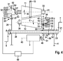
- Figure 4 shows a crank mechanism 2 for an electric bicycle according to a third embodiment, which essentially corresponds to the first embodiment.
- a sensor 61 is additionally provided for detecting a force applied by a driver via the cranks 7, 8.
- the sensor 61 is arranged in front of the bevel ring gear 10 in the direction of force flow.
- a pressing device 62 is provided between the second gear 27 of the first gear stage 25 and the input shaft 41 of the input cone 11.
- the pressing device 62 of this exemplary embodiment comprises a ball 63 which runs on an inclined plane 64 which is arranged on the input shaft 41. A pedal force measurement by means of the force sensor 61 is thus possible via the pressing device 62.
- the force sensor 61 is connected to a control unit 60, which is set up to control the electric drive 3 based on the detected values by the sensor 61. This enables optimum control of the electric drive 3 as a function of a pedal force applied by a driver and the support by the electric drive 3 desired by the driver. Furthermore, the pedal force introduced by the driver is used to preload the conical ring gear 10, more precisely the input cone 11, in the axial direction in addition to an existing spring 63.
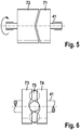
- Figures 5 and 6 Two alternative configurations for the pressing device 62 are shown.
- Figure 5 shows an embodiment with a positive cone 71 and a negative cone 72.
- Figure 6 shows an alternative pressing device 62, comprising a first disk 73, a second disk 74 and a plurality of balls 75, which are arranged between the two disks 73, 74.
- the ball 75 are partially in pockets, which are provided in the two disks 73, 74.
Landscapes
- Engineering & Computer Science (AREA)
- Chemical & Material Sciences (AREA)
- Combustion & Propulsion (AREA)
- Mechanical Engineering (AREA)
- Transportation (AREA)
- Transmission Devices (AREA)
- Friction Gearing (AREA)
- Structure Of Transmissions (AREA)
- Connection Of Motors, Electrical Generators, Mechanical Devices, And The Like (AREA)
Description
- Die vorliegende Erfindung betrifft ein motorisch und/oder mit Muskelkraft betreibbares Fahrzeug, insbesondere ein Elektrofahrrad, mit einem Kegelringgetriebe.
- Beispielsweise sind Elektrofahrräder aus dem Stand der Technik mit unterschiedlichen Ausgestaltungen bekannt. Hierbei gibt es Elektrofahrräder, bei denen der elektrische Antrieb im Bereich des Tretlagers (Mittelmotorkonzept) angeordnet ist. Über eine Kette wird dann ein Hinterrad angetrieben. Hierbei kann am Hinterrad eine Schalteinrichtung, z.B. eine Kettenschaltung oder Nabenschaltung oder dergleichen, angeordnet sein. Es wäre hier wünschenswert, weitere alternative Anordnungen, insbesondere von Schalteinrichtungen, zu haben.
- Die
NL 7304436 - Die
EP 1855028 A1 offenbart ein Kegelringgetriebe mit einem zwischen zwei Kegeln verschieblich angeordneten Übertragungsring. Einer der Kegel dient als Antrieb, der andere als Abtrieb des Kegelringgetriebes. Durch Verschieben des Rings kann die Übersetzung des Getriebes eingestellt werden. - Das erfindungsgemäße mit Motor- und/oder Muskelkraft betreibbare Fahrzeug, insbesondere Elektrofahrrad, mit den Merkmalen des Anspruchs 1 weist den Vorteil auf, dass ein besonders kompakter Aufbau eines elektrischen Antriebs und einer Schalteinrichtung möglich ist. Dabei ist ein besonderer Vorteil, dass die Schalteinrichtung eine stufenlose Änderung einer Übersetzung ermöglicht. Hierbei kann erfindungsgemäß eine besonders kompakte Bauweise ermöglicht werden. Weiterhin kann durch eine stufenlose Änderung einer Übersetzung ein besonders gutes Zusammenspiel zwischen einem Pedalantrieb und einem elektrischen Antrieb ermöglicht werden, so dass die vorliegende Erfindung besonders für ein Elektrofahrrad geeignet ist. Hierbei kann eine Änderung der Übersetzung auch unter Last problemlos ermöglicht werden und insbesondere kann auch ein Geräusch bei einer Änderung des Übersetzungsverhältnisses vermieden werden, so dass eine erfindungsgemäße Änderung des Übersetzungsverhältnisses sehr leise ist. Dies wird erfindungsgemäß dadurch erreicht, dass das Fahrzeug einen Kurbeltrieb mit einer Tretlagerwelle, ein Kettenblatt und einen elektrischen Antrieb aufweist. Ferner umfasst das Fahrzeug ein stufenloses Kegelringgetriebe für eine stufenlose Änderung des Übersetzungsverhältnisses. Das Kegelringgetriebe ist dabei am Kurbeltrieb angeordnet und ist derart mit dem Kurbeltrieb verbunden und eingerichtet, ein durch einen Fahrer erzeugtes Drehmoment auf das Kettenblatt zu übertragen. Das stufenlose Kegelringgetriebe hat weiterhin den Vorteil, dass ein Schalten unter Last möglich ist und ein Fahrer keine Übersetzungssprünge bemerkt. Hieraus resultiert ein besonders vorteilhaftes Fahrgefühl, insbesondere in Kombination mit dem elektrischen Antrieb, da dessen Drehmoment und Drehzahl ebenfalls stufenlos steuerbar ist.
- Erfindungsgemäß ist der elektrische Antrieb innerhalb eines der Kegel angeordnet. Auch hierdurch kann eine noch kompaktere Abmessung der Baueinheit erreicht werden.
- Die Unteransprüche zeigen bevorzugte Weiterbildungen der Erfindung.
- Für einen besonders kompakten Aufbau ist vorzugsweise das Kegelringgetriebe innerhalb eines Gehäuses des Kurbeltriebs angeordnet.
- Weiter bevorzugt weist das Fahrzeug eine Getriebestufe auf, über welche der elektrische Antrieb mit dem Kettenblatt verbunden ist und das Kettenblatt antreibt. Eine Verbindung zwischen der Getriebestufe und dem Kettenblatt kann beispielsweise über eine Hülse oder dergleichen erfolgen. Die Hülse ist vorzugsweise über einen Freilauf an der Tretlagerwelle gelagert.
- Weiter bevorzugt umfasst das Fahrzeug ein Planetengetriebe, welches zwischen einer Abtriebswelle des Kegelringgetriebes und dem Kettenblatt angeordnet ist. Besonders bevorzugt treibt die Abtriebswelle des Kegelringgetriebes dabei ein Sonnenrad des Planetengetriebes an. Weiter bevorzugt weist ein Hohlrad des Planetengetriebes auch eine Außenverzahnung auf, über welche ein Abtrieb aus dem Planetengetriebe, vorzugsweise auf ein Zahnrad der Getriebestufe zwischen dem elektrischen Antrieb und dem Kettenblatt, erfolgt.
- Gemäß einer weiteren bevorzugten Ausgestaltung der Erfindung ist eine Übersetzung des Kegelringgetriebes mittels eines durch den Fahrer betätigbaren Aktuators veränderbar. Das Kegelringgetriebe umfasst einen Eingangskegel, einen Ausgangskegel und einen zwischen den beiden Kegeln angeordneten Kegelring. Der Aktuator betätigt dabei die Stellung des Kegelrings, um so stufenlos ein Übersetzungsverhältnis zwischen den beiden Kegeln zu verändern.
- Ein besonders kompakter Aufbau ergibt sich, wenn die Tretlagerwelle durch einen der Kegel des Kegelringgetriebes, insbesondere durch den Ausgangskegel, verläuft.
- Vorzugsweise umfasst das Fahrzeug ferner eine Steuereinheit und einen Sensor zur Erfassung einer Kraft, welche durch den Fahrer aufgebracht wird. Hierdurch kann ein Kraftwert bestimmt werden, wobei die Steuereinheit eingerichtet ist, den elektrischen Antrieb des Fahrzeugs, basierend auf dem erfassten Kraftwert, zu steuern. Zusätzlich oder alternativ kann auch ein vom Fahrer aufgebrachtes Drehmoment zur Steuerung des elektrischen Antriebs verwendet werden.
- Besonders bevorzugt umfasst das Kegelringgetriebe eine Kegelvorspanneinrichtung, welche einen der Kegel in Axialrichtung des Kegels vorspannt. Dabei ist der Sensor zur Erfassung einer durch einen Fahrer aufgebrachten Kraft an der Kegelvorspanneinrichtung angeordnet. Die Kegelvorspanneinrichtung umfasst dabei besonders bevorzugt eine schiefe Ebene mit einer Kugel, oder eine Kegelanordnung mit einem Positivkegel und einem Negativkegel oder eine Druckkupplungsanordnung mit zwei Scheiben mit Taschen und Kugeln, wobei die Kugeln in den Taschen zwischen den beiden Scheiben angeordnet sind.
- Gemäß einer weiteren bevorzugten Ausgestaltung der Erfindung ist das Kegelringgetriebe oberhalb der Tretlagerwelle angeordnet. Weiter bevorzugt ist der elektrische Motor unterhalb der Tretlagerwelle angeordnet.
- Das erfindungsgemäße Fahrzeug ist besonders bevorzugt ein Elektrofahrrad, wobei durch die Verwendung des erfindungsgemäßen stufenlosen Kegelringgetriebes auf eine Schalteinrichtung an einem Hinterrad des Fahrrads verzichtet werden kann. Die Anordnung sowohl des elektrischen Antriebs als auch der Schalteinrichtung in Form des Kegelringgetriebes am Tretlager ermöglicht dabei ferner einen besonders tiefen Schwerpunkt des Elektrofahrrads, was sich positiv auf die Handling-Eigenschaften des Elektrofahrrads auswirkt.
- Nachfolgend werden bevorzugte Ausführungsbeispiele unter Bezugnahme auf die begleitende Zeichnung im Detail beschrieben. In den Ausführungsbeispielen sind gleiche bzw. funktional gleiche Teile jeweils mit den gleichen Bezugszeichen bezeichnet. In der Zeichnung ist:
- Figur 1
- eine schematische Darstellung eines Elektrofahrrads gemäß einem ersten nicht beanspruchten Ausführungsbeispiel,
- Figur 2
- eine schematische Ansicht eines Kurbeltriebs eines Elektrofahrrads gemäß dem ersten nicht beanspruchten Ausführungsbeispiel,
- Figur 3
- eine schematische Ansicht eines Kurbeltriebs eines Elektrofahrrads gemäß einem zweiten nicht beanspruchten Ausführungsbeispiel,
- Figur 4
- eine schematische Ansicht eines Kurbeltriebs eines Elektrofahrrads gemäß einem dritten nicht beanspruchten Ausführungsbeispiel, und
- Figuren 5 und 6
- schematische Ansichten von alternativen Kegelvorspanneinrichtungen.
- Nachfolgend wird unter Bezugnahme auf die
Figuren 1 und 2 ein Elektrofahrrad 1 gemäß einem ersten bevorzugten Ausführungsbeispiel der Erfindung im Detail beschrieben. - Wie aus
Figur 1 ersichtlich ist, umfasst das Elektrofahrrad 1 einen Kurbeltrieb 2, in welchen ein elektrischer Antrieb 3 (sieheFigur 2 ) integriert ist. Ein Kettenblatt 4 gibt eine Antriebskraft über eine Kette 5 an ein an einem Hinterrad 9 angeordnetes Ritzel 6 ab. Die Bezugszeichen 7 und 8 bezeichnen Kurbeln mit Pedalen des Elektrofahrrads. - In
Figur 2 ist im Detail der Kurbeltrieb 2 gezeigt. Der Kurbeltrieb 2 umfasst neben den beiden Kurbeln 7, 8 eine Tretlagerwelle 20, welche an einem ersten Tretlager 22 und einem zweiten Tretlager 23 gelagert ist. Eine von einem Fahrer aufgebrachte Tretkraft wird dabei über die Pedale auf die Tretlagerwelle 20 übertragen. Eine Drehung der Tretlagerwelle ist durch den Pfeil A angedeutet. - An der Tretlagerwelle 20 ist ein erstes Zahnrad 26 angeordnet, welches mit einem zweiten Zahnrad 27 kämmt. Die beiden Zahnräder 26, 27 bilden dabei eine erste Getriebestufe 25. Das zweite Zahnrad 27 ist dabei an einer Eingangswelle 41 eines Kegelringgetriebes 10 angeordnet.
- Das Kegelringgetriebe 10 umfasst neben der Eingangswelle 41 einen Eingangskegel 11, einen Ausgangskegel 12 und einen zwischen dem Eingangskegel und dem Ausgangskegel angeordneten Kegelring 13. Zur Vorspannung des Kegelringgetriebes in Axialrichtung ist eine Kegelvorspanneinrichtung 14 mit einer Feder vorgesehen. Eine Drehung des Eingangskegels 11 ist durch den Pfeil B angedeutet und eine Drehung des Ausgangskegels 12 ist durch den Pfeil C angedeutet. Der Ausgangskegel 12 ist an einer Ausgangswelle 42 angeordnet, wobei, wie in
Figur 2 gezeigt, die Eingangswelle 41 parallel zur Ausgangswelle 42 ist. Das Bezugszeichen 44 bezeichnet dabei eine Achse der Eingangswelle und das Bezugszeichen 45 eine Achse der Ausgangswelle. - Die Eingangswelle 41 ist an einem ersten Axiallager 31 sowie einem ersten Radiallager 32 und einem zweiten Radiallager 33 gelagert. Die Ausgangswelle 42 ist an einem zweiten Axiallager 34, einem dritten Radiallager 35 und einem vierten Radiallager 36 gelagert.
- Der elektrische Antrieb 3 weist eine Motorausgangswelle 46 auf, an welcher ein Motorritzel 51 angeordnet ist. Das Motorritzel 51 ist Teil einer zweiten Getriebestufe 50, wobei die zweite Getriebestufe 50 noch ein Abtriebszahnrad 52 umfasst. Das Abtriebszahnrad 52 ist an einer Hülse 53 angeordnet, an welcher auch das Kettenblatt 4 angeordnet ist. Die Hülse 53 ist dabei über ein erstes Freilauflager 54 und ein zweites Freilauflager 55 an der Tretlagerwelle 20 gelagert. Eine Motorachse ist mit dem Bezugszeichen 43 bezeichnet.
- Ferner umfasst das Elektrofahrrad 1 ein Planetengetriebe 15. Das Planetengetriebe 15 ist einerseits mit dem Kegelgetriebe 10 und andererseits mit der zweiten Getriebestufe 50 verbunden. Genauer umfasst das Planetengetriebe 15 ein Sonnenrad 16, mehrere Planetenräder 17, einen Planetenradträger 18 und ein Hohlrad 19. Der Planetenradträger 18 steht hierbei fest. Das Hohlrad 19 weist neben der üblichen Innenverzahnung noch zusätzlich eine Außenverzahnung auf. Das Sonnenrad 16 ist dabei auf der Ausgangswelle 42 des Kegelringgetriebes 10 angeordnet. Das Sonnenrad 16 kämmt mit den Planetenrädern 17, welche ihrerseits mit dem Hohlrad 19 kämmen. Die Außenverzahnung des Hohlrads 19 befindet sich mit dem Abtriebszahnrad 52 der zweiten Getriebestufe 50 in Eingriff.
- Somit gehen sowohl das vom elektrischen Motor 3 (falls angetrieben) als auch das vom Fahrer aufgebrachte Drehmoment über das Kegelringgetriebe 10 jeweils auf das Abtriebszahnrad 52 der zweiten Getriebestufe 50. Über die Hülse 53 und das Kettenblatt 4 wird das Drehmoment auf die Kette 5 und das Ritzel 6 am Hinterrad übertragen.
- Hierbei übernimmt das Kegelringgetriebe 10 die Funktion einer Schalteinrichtung, so dass keine zusätzliche Schalteinrichtung am Hinterrad im Bereich des Ritzels 6 vorgesehen werden muss. Eine Änderung der Übersetzung am Kegelringgetriebe erfolgt durch Bewegung des Kegelrings 13 in axialer Richtung, was beispielsweise mittels eines elektrischen Aktuators ausführbar ist.
- Eine Verbindung des Eingangskegels 11 mit der Eingangswelle 41 bzw. des Ausgangskegels 12 mit der Ausgangswelle 42 kann über eine Passfederverbindung oder eine Keilwelle ermöglicht werden. Hierdurch wird die axiale Bewegbarkeit der Kegel in gewissem Umfang sichergestellt.
- Um einen möglichst kleinen Schlupf zu erhalten, ist vorzugsweise der Kegelring 13 gegenüber den Kegeln ballig ausgeführt. Dies führt auch zu einer verbesserten Schmierstoffversorgung, da hierdurch ein Kapillarspalt zwischen dem Kegelring 13 und den Mantelflächen der Kegel erreicht wird.
- Wenn nun ein Fahrer in die Pedale tritt, wird das Drehmoment über die erste Getriebestufe 25 in das Kegelringgetriebe 10 eingegeben. Hier erfolgt eine entsprechend den Wünschen des Fahrers eingestellte Übersetzung bzw. Untersetzung und das derart geänderte Drehmoment wird in das Planetengetriebe 15 eingegeben. Das Planetengetriebe 15 gibt das geänderte Drehmoment dann über das Abtriebszahnrad 52 der zweiten Getriebestufe 50 an das Kettenblatt 4 weiter. Zusätzlich oder auch nur ausschließlich kann auch der elektrische Antrieb 3 betrieben werden, dessen Drehmoment über die zweite Getriebestufe 50 ebenfalls auf das Kettenblatt 4 übertragen wird.
- Somit kann sowohl eine Schalteinrichtung als auch ein elektrischer Antrieb am Kurbeltrieb 2 angeordnet werden. Vorzugsweise sind dabei der elektrische Antrieb 3 und die als Kegelringgetriebe ausgebildete Schalteinrichtung in einem gemeinsamen Gehäuse des Kurbeltriebs 2 angeordnet. Wie aus
Figur 2 ersichtlich ist, ist dabei das Kegelringgetriebe 10 über der Tretlagerwelle 20 angeordnet und der elektrische Antrieb 3 unterhalb der Tretlagerwelle 20 angeordnet. Das Kegelringgetriebe 10 kann dabei eine stufenlose Übersetzung eines von einem Fahrer aufgebrachten Drehmoments ermöglichen. Hierdurch ist ein besonders gutes Zusammenspiel des vom Fahrer aufgebrachten Drehmoments und des vom elektrischen Antrieb 3 bereitgestellten Drehmoments möglich. Insbesondere ermöglicht das Kegelringgetriebe 10 auch eine Änderung der Übersetzung unter Last, so dass auch bei einer Änderung einer Übersetzung der elektrische Antrieb 3 bei Bedarf kontinuierlich angetrieben werden kann und zusätzliches Drehmoment für einen Vortrieb bereitstellen kann. -
Figur 3 zeigt einen Kurbeltrieb gemäß einem zweiten Ausführungsbeispiel, bei dem im Unterschied zum ersten Ausführungsbeispiel die Tretlagerwelle 20 in einem der Kegel des Kegelringgetriebes 10 angeordnet ist. Genauer ist die Tretlagerwelle 20 im Ausgangskegel 12 des Kegelringgetriebes angeordnet. Dadurch fallen die Achse der Tretlagerwelle und die Achse des Ausgangskegels 12 zusammen. Das Elektrofahrrad des zweiten Ausführungsbeispiels umfasst ebenfalls ein Planetengetriebe 15, wobei der Ausgang des Planetengetriebes 15 beim zweiten Ausführungsbeispiel über den Planetenradträger 18 erfolgt. Wie ausFigur 3 ersichtlich ist, ist der Planetenradträger 18 mit dem Abtriebszahnrad 52 der zweiten Getriebestufe 50 verbunden. Dieser Aufbau des Kurbeltriebs ermöglicht eine noch kompaktere Lösung für die Integration des Kegelringgetriebes 10 und des elektrischen Antriebs 3 in den Kurbeltrieb 2 des Fahrrads. Der Ausgangskegel 12 ist dabei über zwei Freilauflager 56, 57 an der Tretlagerwelle 20 gelagert. -
Figur 4 zeigt einen Kurbeltrieb 2 für ein Elektrofahrrad gemäß einem dritten Ausführungsbeispiel, welches im Wesentlichen dem ersten Ausführungsbeispiel entspricht. Im Unterschied dazu ist beim dritten Ausführungsbeispiel zusätzlich noch ein Sensor 61 zur Erfassung einer durch einen Fahrer über die Kurbeln 7, 8 aufgebrachten Kraft vorgesehen. Der Sensor 61 ist dabei in Kraftflussrichtung vor dem Kegelringgetriebe 10 angeordnet. Wie ausFigur 4 ersichtlich ist, ist eine Anpressvorrichtung 62 zwischen dem zweiten Zahnrad 27 der ersten Getriebestufe 25 und der Eingangswelle 41 des Eingangskegels 11 vorgesehen. Die Anpressvorrichtung 62 dieses Ausführungsbeispiels umfasst eine Kugel 63, welche auf einer schiefen Ebene 64, die an der Eingangswelle 41 angeordnet ist, läuft. Über die Anpressvorrichtung 62 ist somit eine Pedalkraftmessung mittels des Kraftsensors 61 möglich. Der Kraftsensor 61 ist mit einer Steuereinheit 60 verbunden, welche eingerichtet ist, basierend auf den erfassten Werten durch den Sensor 61 den elektrischen Antrieb 3 anzusteuern. Dadurch kann eine optimale Ansteuerung des elektrischen Antriebs 3 in Abhängigkeit von einer von einem Fahrer aufgebrachten Pedalkraft und vom Fahrer gewünschten Unterstützung durch den elektrischen Antrieb 3 ermöglicht werden. Ferner wird die vom Fahrer eingebrachte Pedalkraft dazu genutzt, das Kegelringgetriebe 10, genauer den Eingangskegel 11, in axialer Richtung zusätzlich zu einer vorhandenen Feder 63 vorzuspannen. - In den
Figuren 5 und 6 sind noch zwei alternative Ausgestaltungen für die Anpressvorrichtung 62 dargestellt.Figur 5 zeigt dabei eine Ausgestaltung mit einem Positivkegel 71 und einem Negativkegel 72.Figur 6 zeigt eine alternative Anpressvorrichtung 62, umfassend eine erste Scheibe 73, eine zweite Scheibe 74 und eine Vielzahl von Kugeln 75, welche zwischen den beiden Scheiben 73, 74 angeordnet sind. Die Kugel 75 liegen dabei teilweise in Taschen, welche in den beiden Scheiben 73, 74 vorgesehen sind.
Claims (10)
- Mit Motorkraft und/oder Pedalkraft betreibbares Fahrzeug, insbesondere Elektrofahrrad, umfassend- einen Kurbeltrieb (2) mit einer Tretlagerwelle (20),- ein Kettenblatt (4), welches ein Antriebsmoment für das Fahrzeug an eine Kette (5) abgibt, und- einen elektrischen Antrieb (3),
gekennzeichnet durch- ein Kegelringgetriebe (10) zur stufenlosen Änderung eines Übersetzungsverhältnisses,- wobei das Kegelringgetriebe (10) und der elektrische Antrieb (3) am Kurbeltrieb (2) angeordnet sind und- wobei das Kegelringgetriebe (10) derart mit dem Kurbeltrieb (2) verbunden ist und eingerichtet ist, ein durch einen Fahrer erzeugtes Drehmoment auf das Kettenblatt (4) zu übertragen, und- wobei der elektrische Antrieb (3) innerhalb eines der Kegel des Kegelringgetriebes (10) angeordnet ist. - Fahrzeug nach Anspruch 1, dadurch gekennzeichnet, dass das Kegelringgetriebe (10) innerhalb eines Gehäuses des Kurbeltriebs angeordnet ist.
- Fahrzeug nach einem der vorhergehenden Ansprüche, dadurch gekennzeichnet, dass der elektrische Antrieb (3) das Kettenblatt (4) über eine Getriebestufe (50) antreibt.
- Fahrzeug nach einem der vorhergehenden Ansprüche, gekennzeichnet durch ein Planetengetriebe (15), welches zwischen einer Abtriebswelle (42) des Kegelringgetriebes (10) und dem Kettenblatt (4) angeordnet ist.
- Fahrzeug nach einem der vorhergehenden Ansprüche, dadurch gekennzeichnet, dass eine Übersetzung des Kegelringgetriebes (10) mittels eines durch einen Fahrer betätigbaren Aktuators (5) veränderbar ist.
- Fahrzeug nach einem der vorhergehenden Ansprüche, dadurch gekennzeichnet, dass die Tretlagerwelle (20) durch einen der Kegel des Kegelringgetriebes (10), insbesondere durch einen Ausgangskegel (12), verläuft.
- Fahrzeug nach einem der vorhergehenden Ansprüche, ferner umfassend eine Steuereinheit (60) und einen Sensor (61) zur Erfassung einer Kraft, welche durch einen Fahrer aufgebracht wird, wobei die Steuereinheit (60) eingerichtet ist, den elektrischen Antrieb (3), basierend auf dem erfassten Kraftwert des Sensors (61) zu steuern.
- Fahrzeug nach Anspruch 7, gekennzeichnet durch eine Kegelvorspanneinrichtung (14), welche einen der Kegel des Kegelringgetriebes (10) in axialer Richtung des Kegels vorspannt, wobei an der Kegelvorspanneinrichtung (14) eine Anpressvorrichtung (62) angeordnet ist und der Sensor (61) an der Anpressvorrichtung (62) angeordnet ist.
- Fahrzeug nach Anspruch 8, dadurch gekennzeichnet, dass die Anpressvorrichtung (62) eine schiefe Ebene mit einer Kugel umfasst oder- eine Kegelanordnung mit einem Positivkegel (71) und einem Negativkegel (72) oder- eine Anordnung mit zwei Scheiben (73, 74) mit Taschen, in welchen Kugeln (75) angeordnet sind.
- Fahrzeug nach einem der vorhergehenden Ansprüche, dadurch gekennzeichnet, dass das Kegelringgetriebe (10) oberhalb der Tretlagerwelle (20) angeordnet ist und/oder dass der elektrische Antrieb (3) unterhalb der Tretlagerwelle (20) angeordnet ist.
Applications Claiming Priority (2)
| Application Number | Priority Date | Filing Date | Title |
|---|---|---|---|
| DE102013206710.0A DE102013206710A1 (de) | 2013-04-15 | 2013-04-15 | Motorisch und mit Muskelkraft betreibbares Fahrzeug |
| PCT/EP2014/054038 WO2014170062A1 (de) | 2013-04-15 | 2014-03-03 | Motorisch und mit muskelkraft betreibbares fahrzeug |
Publications (2)
| Publication Number | Publication Date |
|---|---|
| EP2986492A1 EP2986492A1 (de) | 2016-02-24 |
| EP2986492B1 true EP2986492B1 (de) | 2020-01-01 |
Family
ID=50193489
Family Applications (1)
| Application Number | Title | Priority Date | Filing Date |
|---|---|---|---|
| EP14707747.3A Active EP2986492B1 (de) | 2013-04-15 | 2014-03-03 | Motorisch und mit muskelkraft betreibbares fahrzeug |
Country Status (5)
| Country | Link |
|---|---|
| US (1) | US9555854B2 (de) |
| EP (1) | EP2986492B1 (de) |
| DE (1) | DE102013206710A1 (de) |
| TW (1) | TWI648196B (de) |
| WO (1) | WO2014170062A1 (de) |
Cited By (1)
| Publication number | Priority date | Publication date | Assignee | Title |
|---|---|---|---|---|
| WO2023158788A1 (en) * | 2022-02-18 | 2023-08-24 | Joseph Francis Keenan | System and method for bicycle transmission |
Families Citing this family (21)
| Publication number | Priority date | Publication date | Assignee | Title |
|---|---|---|---|---|
| DE102014221512A1 (de) * | 2014-10-23 | 2016-04-28 | Robert Bosch Gmbh | Koaxial angeordnetes Reibringgetriebe für ein mit Motorkraft und/oder Pedalkraft betreibbares Fahrzeug |
| CN104843138A (zh) * | 2015-04-21 | 2015-08-19 | 谢腾 | 一种用于自行车的无级变速器 |
| DE102016203661A1 (de) * | 2016-03-07 | 2017-09-07 | Volkswagen Aktiengesellschaft | Pedelec-Antriebsanordnung |
| DE102016209275B3 (de) * | 2016-05-30 | 2017-09-28 | Robert Bosch Gmbh | Steuerungsverfahren und Vorrichtungen zur Steuerung des Elektromotors eines Elektrofahrrads |
| JP6705740B2 (ja) * | 2016-12-21 | 2020-06-03 | 株式会社シマノ | 自転車用変速機および自転車用内装変速ハブ |
| CN106627971A (zh) * | 2016-12-26 | 2017-05-10 | 苏州万佳电器有限公司 | 自行车用变速系统及包含该系统的助力自行车用变速方法 |
| DE102017003945B4 (de) | 2017-04-24 | 2022-01-13 | Oechsler Ag | Elektromotorischer Fahrradzusatzantrieb mit stufenlos variabler Übersetzung |
| CN109693757B (zh) * | 2017-10-23 | 2020-06-12 | 张占庚 | 自行车无段自动变速装置 |
| JP7343266B2 (ja) * | 2017-10-27 | 2023-09-12 | 株式会社シマノ | 人力駆動車両用制御装置 |
| JP7193230B2 (ja) * | 2017-10-31 | 2022-12-20 | 株式会社シマノ | 人力駆動車両用制御装置 |
| DE102017219601B4 (de) * | 2017-11-06 | 2025-10-02 | Zf Friedrichshafen Ag | Antriebsanordnung eines Pedelecs |
| KR102034744B1 (ko) * | 2019-07-29 | 2019-10-21 | 백성구 | 자전거 구동장치 |
| CN111776893B (zh) * | 2020-07-01 | 2022-02-22 | 以太龙精密机械江苏有限公司 | 一种高效率线缆收放装置 |
| DE102021101415A1 (de) * | 2021-01-22 | 2022-07-28 | Karlheinz Nicolai | Tretlagerschaltung für ein Elektrofahrrad und Elektrofahrrad mit einer solchen Tretlagerschaltung |
| TW202237469A (zh) * | 2021-03-03 | 2022-10-01 | 德商查發傅利得利夏芬股份有限公司 | 用於由踏板操控的車輛之換檔方法 |
| DE102022102070A1 (de) * | 2022-01-28 | 2023-08-03 | Brose Antriebstechnik GmbH & Co. Kommanditgesellschaft, Berlin | Antriebssystem für ein Elektrofahrrad mit Berechnung eines Drehmoments an der Tretlagerwelle für die Steuerung der Unterstützungsleistung |
| US12325492B2 (en) | 2022-05-18 | 2025-06-10 | Innovative Engineering LLC | Automatic transmission system for a bicycle |
| CN115158526B (zh) * | 2022-08-01 | 2024-06-04 | 深圳哲轮科技有限公司 | 一种链条调节器以及应用该调节器的自行车 |
| FR3142788A1 (fr) * | 2022-12-05 | 2024-06-07 | IFP Energies Nouvelles | Transmission variable avec galets coniques ou tronconiques et une couronne |
| IT202300016692A1 (it) * | 2023-08-04 | 2025-02-04 | Muviq S R L | Sistema di trasmissione migliorato per veicolo a pedali e relativo metodo di controllo |
| WO2025032457A1 (en) * | 2023-08-04 | 2025-02-13 | Muviq S.r.l. | Improved transmission system for a pedal vehicle and related control method |
Family Cites Families (7)
| Publication number | Priority date | Publication date | Assignee | Title |
|---|---|---|---|---|
| FR2180709A1 (de) | 1972-04-18 | 1973-11-30 | Solo Kleinmotoren Gmbh | |
| DE2245767A1 (de) | 1972-09-18 | 1974-03-28 | Fichtel & Sachs Ag | Batterie-elektrischer fahrzeugantrieb |
| US3873128A (en) * | 1973-05-29 | 1975-03-25 | Trans World Products Inc | Drive transmission for a bicycle or the like |
| DE102004003716A1 (de) * | 2004-01-24 | 2005-08-11 | Zf Friedrichshafen Ag | Kegelringgetriebe |
| DE102004003691B4 (de) * | 2004-01-24 | 2018-10-31 | Zf Friedrichshafen Ag | Kegelringgetriebe |
| EP1855028B1 (de) * | 2006-05-11 | 2009-03-11 | Getrag Ford Transmissions GmbH | Kegelringgetriebe mit optimiertem Reibring |
| DE102011008863A1 (de) * | 2010-08-16 | 2012-02-16 | Ulrich Rohs | Kegelreibringgetriebe und Verfahren für ein Kegelreibringgetriebe |
-
2013
- 2013-04-15 DE DE102013206710.0A patent/DE102013206710A1/de not_active Withdrawn
-
2014
- 2014-03-03 WO PCT/EP2014/054038 patent/WO2014170062A1/de not_active Ceased
- 2014-03-03 EP EP14707747.3A patent/EP2986492B1/de active Active
- 2014-03-03 US US14/784,540 patent/US9555854B2/en not_active Expired - Fee Related
- 2014-04-14 TW TW103113528A patent/TWI648196B/zh not_active IP Right Cessation
Non-Patent Citations (1)
| Title |
|---|
| None * |
Cited By (2)
| Publication number | Priority date | Publication date | Assignee | Title |
|---|---|---|---|---|
| WO2023158788A1 (en) * | 2022-02-18 | 2023-08-24 | Joseph Francis Keenan | System and method for bicycle transmission |
| AU2023220084B2 (en) * | 2022-02-18 | 2024-10-31 | Joseph Francis Keenan | System and method for bicycle transmission |
Also Published As
| Publication number | Publication date |
|---|---|
| TW201501997A (zh) | 2015-01-16 |
| US9555854B2 (en) | 2017-01-31 |
| US20160090151A1 (en) | 2016-03-31 |
| DE102013206710A1 (de) | 2014-10-16 |
| TWI648196B (zh) | 2019-01-21 |
| EP2986492A1 (de) | 2016-02-24 |
| WO2014170062A1 (de) | 2014-10-23 |
Similar Documents
| Publication | Publication Date | Title |
|---|---|---|
| EP2986493B1 (de) | Motorisch und mit muskelkraft betreibbares fahrzeug | |
| DE102013206710A1 (de) | Motorisch und mit Muskelkraft betreibbares Fahrzeug | |
| EP3036151B1 (de) | Fahrzeug mit elektrischem hilfsantrieb und stufenlos verstellbarem planetengetriebe | |
| EP3509935B1 (de) | Antriebsanordnung und fahrzeug | |
| DE102014007271A1 (de) | Stufenloses Tretlagergetriebe für LEV's ( Light electric vehicles) mit integrierbarem Elektromotor | |
| EP2669549A1 (de) | Fahrradgetriebe | |
| EP3209544B1 (de) | Koaxial angeordnetes reibringgetriebe für ein mit motorkraft und/oder pedalkraft betreibbares fahrzeug | |
| EP4463361B1 (de) | Fahrradantrieb und fahrrad | |
| WO2016177494A1 (de) | Anordnung, insbesondere elektrisch und/oder mit muskelkraft antreibbares fahrzeug mit stufenloser schaltung | |
| DE102018104758A1 (de) | Getriebe | |
| EP2930097B1 (de) | Antrieb für ein elektrofahrrad | |
| DE102013012160B4 (de) | Stufenloses Nabengetriebe für Fahrräder, Pedelecs und e-bikes, mit und ohne automatische Anpassung des Übersetzungsverhältnisses an die Fahrgeschwindigkeit. | |
| DE102024113872B4 (de) | Antriebsvorrichtung für ein Fahrrad mit einem stufenlos verstellbaren Getriebe | |
| DE102015106564B3 (de) | Antriebsanordnung für ein Fahrrad | |
| DE102014016395B4 (de) | Unter Last schaltbares Getriebe für Fahrzeuge | |
| DE102012023150A1 (de) | Stufenloses Tretlagergetriebe für Fahrräder, Pedelecs und E-Bikes mit optional integrierbarem Elektromotor | |
| DE102022001739A1 (de) | Tretlagerschaltung mit Schaltvorrichtung für ein Fahrrad und ein Fahrrad mit einer solchen Tretlagerschaltung | |
| EP2298636B9 (de) | Getriebeanordnung für ein mit einem Hilfsantrieb ausgestattetes Fahrrad | |
| DE102024112067B4 (de) | Antriebsvorrichtung für ein Fahrrad mit einem stufenlos verstellbaren Getriebe | |
| DE102023207638B3 (de) | Tretlagerschaltung für ein Fahrrad sowie Fahrrad mit einem Antriebsstrang mit einer solchen Tretlagerschaltung | |
| WO2017080726A1 (de) | Reibringgetriebe, antrieb und fahrzeug | |
| DE102024112070B4 (de) | Antriebsvorrichtung für ein Fahrrad mit einem stufenlos verstellbaren Getriebe | |
| DE102024113530A1 (de) | Antriebsvorrichtung für ein Fahrrad mit einem stufenlos verstellbaren Getriebe | |
| DE102024113536A1 (de) | Antriebsvorrichtung für ein Fahrrad mit einem stufenlos verstellbaren Getriebe | |
| EP4512709A1 (de) | Getriebeeinheit mit schaltvorrichtung für ein fahrrad |
Legal Events
| Date | Code | Title | Description |
|---|---|---|---|
| PUAI | Public reference made under article 153(3) epc to a published international application that has entered the european phase |
Free format text: ORIGINAL CODE: 0009012 |
|
| 17P | Request for examination filed |
Effective date: 20151116 |
|
| AK | Designated contracting states |
Kind code of ref document: A1 Designated state(s): AL AT BE BG CH CY CZ DE DK EE ES FI FR GB GR HR HU IE IS IT LI LT LU LV MC MK MT NL NO PL PT RO RS SE SI SK SM TR |
|
| AX | Request for extension of the european patent |
Extension state: BA ME |
|
| DAX | Request for extension of the european patent (deleted) | ||
| REG | Reference to a national code |
Ref country code: DE Ref legal event code: R079 Ref document number: 502014013376 Country of ref document: DE Free format text: PREVIOUS MAIN CLASS: B62M0006550000 Ipc: B62M0011120000 |
|
| GRAP | Despatch of communication of intention to grant a patent |
Free format text: ORIGINAL CODE: EPIDOSNIGR1 |
|
| STAA | Information on the status of an ep patent application or granted ep patent |
Free format text: STATUS: GRANT OF PATENT IS INTENDED |
|
| RIC1 | Information provided on ipc code assigned before grant |
Ipc: B62M 11/12 20060101AFI20190725BHEP |
|
| INTG | Intention to grant announced |
Effective date: 20190816 |
|
| GRAS | Grant fee paid |
Free format text: ORIGINAL CODE: EPIDOSNIGR3 |
|
| GRAA | (expected) grant |
Free format text: ORIGINAL CODE: 0009210 |
|
| STAA | Information on the status of an ep patent application or granted ep patent |
Free format text: STATUS: THE PATENT HAS BEEN GRANTED |
|
| AK | Designated contracting states |
Kind code of ref document: B1 Designated state(s): AL AT BE BG CH CY CZ DE DK EE ES FI FR GB GR HR HU IE IS IT LI LT LU LV MC MK MT NL NO PL PT RO RS SE SI SK SM TR |
|
| REG | Reference to a national code |
Ref country code: GB Ref legal event code: FG4D Free format text: NOT ENGLISH |
|
| REG | Reference to a national code |
Ref country code: AT Ref legal event code: REF Ref document number: 1219471 Country of ref document: AT Kind code of ref document: T Effective date: 20200115 Ref country code: CH Ref legal event code: EP |
|
| REG | Reference to a national code |
Ref country code: IE Ref legal event code: FG4D Free format text: LANGUAGE OF EP DOCUMENT: GERMAN |
|
| REG | Reference to a national code |
Ref country code: DE Ref legal event code: R096 Ref document number: 502014013376 Country of ref document: DE |
|
| REG | Reference to a national code |
Ref country code: NL Ref legal event code: FP |
|
| RAP2 | Party data changed (patent owner data changed or rights of a patent transferred) |
Owner name: ROBERT BOSCH GMBH |
|
| REG | Reference to a national code |
Ref country code: LT Ref legal event code: MG4D |
|
| PG25 | Lapsed in a contracting state [announced via postgrant information from national office to epo] |
Ref country code: NO Free format text: LAPSE BECAUSE OF FAILURE TO SUBMIT A TRANSLATION OF THE DESCRIPTION OR TO PAY THE FEE WITHIN THE PRESCRIBED TIME-LIMIT Effective date: 20200401 Ref country code: FI Free format text: LAPSE BECAUSE OF FAILURE TO SUBMIT A TRANSLATION OF THE DESCRIPTION OR TO PAY THE FEE WITHIN THE PRESCRIBED TIME-LIMIT Effective date: 20200101 Ref country code: RS Free format text: LAPSE BECAUSE OF FAILURE TO SUBMIT A TRANSLATION OF THE DESCRIPTION OR TO PAY THE FEE WITHIN THE PRESCRIBED TIME-LIMIT Effective date: 20200101 Ref country code: LT Free format text: LAPSE BECAUSE OF FAILURE TO SUBMIT A TRANSLATION OF THE DESCRIPTION OR TO PAY THE FEE WITHIN THE PRESCRIBED TIME-LIMIT Effective date: 20200101 Ref country code: PT Free format text: LAPSE BECAUSE OF FAILURE TO SUBMIT A TRANSLATION OF THE DESCRIPTION OR TO PAY THE FEE WITHIN THE PRESCRIBED TIME-LIMIT Effective date: 20200527 Ref country code: CZ Free format text: LAPSE BECAUSE OF FAILURE TO SUBMIT A TRANSLATION OF THE DESCRIPTION OR TO PAY THE FEE WITHIN THE PRESCRIBED TIME-LIMIT Effective date: 20200101 |
|
| PG25 | Lapsed in a contracting state [announced via postgrant information from national office to epo] |
Ref country code: GR Free format text: LAPSE BECAUSE OF FAILURE TO SUBMIT A TRANSLATION OF THE DESCRIPTION OR TO PAY THE FEE WITHIN THE PRESCRIBED TIME-LIMIT Effective date: 20200402 Ref country code: HR Free format text: LAPSE BECAUSE OF FAILURE TO SUBMIT A TRANSLATION OF THE DESCRIPTION OR TO PAY THE FEE WITHIN THE PRESCRIBED TIME-LIMIT Effective date: 20200101 Ref country code: SE Free format text: LAPSE BECAUSE OF FAILURE TO SUBMIT A TRANSLATION OF THE DESCRIPTION OR TO PAY THE FEE WITHIN THE PRESCRIBED TIME-LIMIT Effective date: 20200101 Ref country code: LV Free format text: LAPSE BECAUSE OF FAILURE TO SUBMIT A TRANSLATION OF THE DESCRIPTION OR TO PAY THE FEE WITHIN THE PRESCRIBED TIME-LIMIT Effective date: 20200101 Ref country code: BG Free format text: LAPSE BECAUSE OF FAILURE TO SUBMIT A TRANSLATION OF THE DESCRIPTION OR TO PAY THE FEE WITHIN THE PRESCRIBED TIME-LIMIT Effective date: 20200401 Ref country code: IS Free format text: LAPSE BECAUSE OF FAILURE TO SUBMIT A TRANSLATION OF THE DESCRIPTION OR TO PAY THE FEE WITHIN THE PRESCRIBED TIME-LIMIT Effective date: 20200501 |
|
| REG | Reference to a national code |
Ref country code: DE Ref legal event code: R097 Ref document number: 502014013376 Country of ref document: DE |
|
| PG25 | Lapsed in a contracting state [announced via postgrant information from national office to epo] |
Ref country code: ES Free format text: LAPSE BECAUSE OF FAILURE TO SUBMIT A TRANSLATION OF THE DESCRIPTION OR TO PAY THE FEE WITHIN THE PRESCRIBED TIME-LIMIT Effective date: 20200101 Ref country code: SK Free format text: LAPSE BECAUSE OF FAILURE TO SUBMIT A TRANSLATION OF THE DESCRIPTION OR TO PAY THE FEE WITHIN THE PRESCRIBED TIME-LIMIT Effective date: 20200101 Ref country code: RO Free format text: LAPSE BECAUSE OF FAILURE TO SUBMIT A TRANSLATION OF THE DESCRIPTION OR TO PAY THE FEE WITHIN THE PRESCRIBED TIME-LIMIT Effective date: 20200101 Ref country code: DK Free format text: LAPSE BECAUSE OF FAILURE TO SUBMIT A TRANSLATION OF THE DESCRIPTION OR TO PAY THE FEE WITHIN THE PRESCRIBED TIME-LIMIT Effective date: 20200101 Ref country code: EE Free format text: LAPSE BECAUSE OF FAILURE TO SUBMIT A TRANSLATION OF THE DESCRIPTION OR TO PAY THE FEE WITHIN THE PRESCRIBED TIME-LIMIT Effective date: 20200101 Ref country code: SM Free format text: LAPSE BECAUSE OF FAILURE TO SUBMIT A TRANSLATION OF THE DESCRIPTION OR TO PAY THE FEE WITHIN THE PRESCRIBED TIME-LIMIT Effective date: 20200101 Ref country code: MC Free format text: LAPSE BECAUSE OF FAILURE TO SUBMIT A TRANSLATION OF THE DESCRIPTION OR TO PAY THE FEE WITHIN THE PRESCRIBED TIME-LIMIT Effective date: 20200101 |
|
| REG | Reference to a national code |
Ref country code: CH Ref legal event code: PL |
|
| PLBE | No opposition filed within time limit |
Free format text: ORIGINAL CODE: 0009261 |
|
| STAA | Information on the status of an ep patent application or granted ep patent |
Free format text: STATUS: NO OPPOSITION FILED WITHIN TIME LIMIT |
|
| 26N | No opposition filed |
Effective date: 20201002 |
|
| REG | Reference to a national code |
Ref country code: BE Ref legal event code: MM Effective date: 20200331 |
|
| PG25 | Lapsed in a contracting state [announced via postgrant information from national office to epo] |
Ref country code: LU Free format text: LAPSE BECAUSE OF NON-PAYMENT OF DUE FEES Effective date: 20200303 |
|
| PG25 | Lapsed in a contracting state [announced via postgrant information from national office to epo] |
Ref country code: LI Free format text: LAPSE BECAUSE OF NON-PAYMENT OF DUE FEES Effective date: 20200331 Ref country code: IE Free format text: LAPSE BECAUSE OF NON-PAYMENT OF DUE FEES Effective date: 20200303 Ref country code: CH Free format text: LAPSE BECAUSE OF NON-PAYMENT OF DUE FEES Effective date: 20200331 Ref country code: FR Free format text: LAPSE BECAUSE OF NON-PAYMENT OF DUE FEES Effective date: 20200331 Ref country code: IT Free format text: LAPSE BECAUSE OF FAILURE TO SUBMIT A TRANSLATION OF THE DESCRIPTION OR TO PAY THE FEE WITHIN THE PRESCRIBED TIME-LIMIT Effective date: 20200101 |
|
| PG25 | Lapsed in a contracting state [announced via postgrant information from national office to epo] |
Ref country code: BE Free format text: LAPSE BECAUSE OF NON-PAYMENT OF DUE FEES Effective date: 20200331 Ref country code: SI Free format text: LAPSE BECAUSE OF FAILURE TO SUBMIT A TRANSLATION OF THE DESCRIPTION OR TO PAY THE FEE WITHIN THE PRESCRIBED TIME-LIMIT Effective date: 20200101 Ref country code: PL Free format text: LAPSE BECAUSE OF FAILURE TO SUBMIT A TRANSLATION OF THE DESCRIPTION OR TO PAY THE FEE WITHIN THE PRESCRIBED TIME-LIMIT Effective date: 20200101 |
|
| GBPC | Gb: european patent ceased through non-payment of renewal fee |
Effective date: 20200401 |
|
| PG25 | Lapsed in a contracting state [announced via postgrant information from national office to epo] |
Ref country code: GB Free format text: LAPSE BECAUSE OF NON-PAYMENT OF DUE FEES Effective date: 20200401 |
|
| REG | Reference to a national code |
Ref country code: AT Ref legal event code: MM01 Ref document number: 1219471 Country of ref document: AT Kind code of ref document: T Effective date: 20200303 |
|
| PG25 | Lapsed in a contracting state [announced via postgrant information from national office to epo] |
Ref country code: AT Free format text: LAPSE BECAUSE OF NON-PAYMENT OF DUE FEES Effective date: 20200303 |
|
| PG25 | Lapsed in a contracting state [announced via postgrant information from national office to epo] |
Ref country code: TR Free format text: LAPSE BECAUSE OF FAILURE TO SUBMIT A TRANSLATION OF THE DESCRIPTION OR TO PAY THE FEE WITHIN THE PRESCRIBED TIME-LIMIT Effective date: 20200101 Ref country code: MT Free format text: LAPSE BECAUSE OF FAILURE TO SUBMIT A TRANSLATION OF THE DESCRIPTION OR TO PAY THE FEE WITHIN THE PRESCRIBED TIME-LIMIT Effective date: 20200101 Ref country code: CY Free format text: LAPSE BECAUSE OF FAILURE TO SUBMIT A TRANSLATION OF THE DESCRIPTION OR TO PAY THE FEE WITHIN THE PRESCRIBED TIME-LIMIT Effective date: 20200101 |
|
| PGFP | Annual fee paid to national office [announced via postgrant information from national office to epo] |
Ref country code: NL Payment date: 20220322 Year of fee payment: 9 |
|
| PG25 | Lapsed in a contracting state [announced via postgrant information from national office to epo] |
Ref country code: MK Free format text: LAPSE BECAUSE OF FAILURE TO SUBMIT A TRANSLATION OF THE DESCRIPTION OR TO PAY THE FEE WITHIN THE PRESCRIBED TIME-LIMIT Effective date: 20200101 Ref country code: AL Free format text: LAPSE BECAUSE OF FAILURE TO SUBMIT A TRANSLATION OF THE DESCRIPTION OR TO PAY THE FEE WITHIN THE PRESCRIBED TIME-LIMIT Effective date: 20200101 |
|
| REG | Reference to a national code |
Ref country code: NL Ref legal event code: MM Effective date: 20230401 |
|
| PG25 | Lapsed in a contracting state [announced via postgrant information from national office to epo] |
Ref country code: NL Free format text: LAPSE BECAUSE OF NON-PAYMENT OF DUE FEES Effective date: 20230401 |
|
| PGFP | Annual fee paid to national office [announced via postgrant information from national office to epo] |
Ref country code: DE Payment date: 20260526 Year of fee payment: 13 |