EP2986459B1 - Longitudinal control arm - Google Patents
Longitudinal control arm Download PDFInfo
- Publication number
- EP2986459B1 EP2986459B1 EP14730899.3A EP14730899A EP2986459B1 EP 2986459 B1 EP2986459 B1 EP 2986459B1 EP 14730899 A EP14730899 A EP 14730899A EP 2986459 B1 EP2986459 B1 EP 2986459B1
- Authority
- EP
- European Patent Office
- Prior art keywords
- axle tube
- control arm
- arrangement section
- trailing arm
- longitudinal control
- Prior art date
- Legal status (The legal status is an assumption and is not a legal conclusion. Google has not performed a legal analysis and makes no representation as to the accuracy of the status listed.)
- Active
Links
- 230000008901 benefit Effects 0.000 description 16
- 238000003466 welding Methods 0.000 description 4
- 238000000034 method Methods 0.000 description 3
- 239000002131 composite material Substances 0.000 description 2
- 239000000463 material Substances 0.000 description 2
- 229910000831 Steel Inorganic materials 0.000 description 1
- 238000009825 accumulation Methods 0.000 description 1
- 230000006978 adaptation Effects 0.000 description 1
- XAGFODPZIPBFFR-UHFFFAOYSA-N aluminium Chemical compound [Al] XAGFODPZIPBFFR-UHFFFAOYSA-N 0.000 description 1
- 229910052782 aluminium Inorganic materials 0.000 description 1
- 230000006835 compression Effects 0.000 description 1
- 238000007906 compression Methods 0.000 description 1
- 238000013016 damping Methods 0.000 description 1
- 230000001419 dependent effect Effects 0.000 description 1
- 239000000428 dust Substances 0.000 description 1
- 230000002349 favourable effect Effects 0.000 description 1
- 238000009434 installation Methods 0.000 description 1
- 239000005871 repellent Substances 0.000 description 1
- 150000003839 salts Chemical class 0.000 description 1
- 238000000926 separation method Methods 0.000 description 1
- 239000010959 steel Substances 0.000 description 1
- 239000000725 suspension Substances 0.000 description 1
- XLYOFNOQVPJJNP-UHFFFAOYSA-N water Substances O XLYOFNOQVPJJNP-UHFFFAOYSA-N 0.000 description 1
Images


Classifications
-
- B—PERFORMING OPERATIONS; TRANSPORTING
- B60—VEHICLES IN GENERAL
- B60G—VEHICLE SUSPENSION ARRANGEMENTS
- B60G7/00—Pivoted suspension arms; Accessories thereof
- B60G7/001—Suspension arms, e.g. constructional features
-
- B—PERFORMING OPERATIONS; TRANSPORTING
- B60—VEHICLES IN GENERAL
- B60G—VEHICLE SUSPENSION ARRANGEMENTS
- B60G7/00—Pivoted suspension arms; Accessories thereof
- B60G7/008—Attaching arms to unsprung part of vehicle
-
- B—PERFORMING OPERATIONS; TRANSPORTING
- B60—VEHICLES IN GENERAL
- B60G—VEHICLE SUSPENSION ARRANGEMENTS
- B60G7/00—Pivoted suspension arms; Accessories thereof
- B60G7/02—Attaching arms to sprung part of vehicle
-
- B—PERFORMING OPERATIONS; TRANSPORTING
- B60—VEHICLES IN GENERAL
- B60G—VEHICLE SUSPENSION ARRANGEMENTS
- B60G9/00—Resilient suspensions of a rigid axle or axle housing for two or more wheels
- B60G9/003—Resilient suspensions of a rigid axle or axle housing for two or more wheels the axle being rigidly connected to a trailing guiding device
-
- B—PERFORMING OPERATIONS; TRANSPORTING
- B60—VEHICLES IN GENERAL
- B60G—VEHICLE SUSPENSION ARRANGEMENTS
- B60G9/00—Resilient suspensions of a rigid axle or axle housing for two or more wheels
- B60G9/02—Resilient suspensions of a rigid axle or axle housing for two or more wheels the axle or housing being pivotally mounted on the vehicle, e.g. the pivotal axis being parallel to the longitudinal axis of the vehicle
-
- B—PERFORMING OPERATIONS; TRANSPORTING
- B60—VEHICLES IN GENERAL
- B60G—VEHICLE SUSPENSION ARRANGEMENTS
- B60G2200/00—Indexing codes relating to suspension types
- B60G2200/30—Rigid axle suspensions
- B60G2200/31—Rigid axle suspensions with two trailing arms rigidly connected to the axle
-
- B—PERFORMING OPERATIONS; TRANSPORTING
- B60—VEHICLES IN GENERAL
- B60G—VEHICLE SUSPENSION ARRANGEMENTS
- B60G2204/00—Indexing codes related to suspensions per se or to auxiliary parts
- B60G2204/10—Mounting of suspension elements
- B60G2204/14—Mounting of suspension arms
- B60G2204/143—Mounting of suspension arms on the vehicle body or chassis
-
- B—PERFORMING OPERATIONS; TRANSPORTING
- B60—VEHICLES IN GENERAL
- B60G—VEHICLE SUSPENSION ARRANGEMENTS
- B60G2204/00—Indexing codes related to suspensions per se or to auxiliary parts
- B60G2204/10—Mounting of suspension elements
- B60G2204/14—Mounting of suspension arms
- B60G2204/148—Mounting of suspension arms on the unsprung part of the vehicle, e.g. wheel knuckle or rigid axle
-
- B—PERFORMING OPERATIONS; TRANSPORTING
- B60—VEHICLES IN GENERAL
- B60G—VEHICLE SUSPENSION ARRANGEMENTS
- B60G2206/00—Indexing codes related to the manufacturing of suspensions: constructional features, the materials used, procedures or tools
- B60G2206/01—Constructional features of suspension elements, e.g. arms, dampers, springs
- B60G2206/012—Hollow or tubular elements
-
- B—PERFORMING OPERATIONS; TRANSPORTING
- B60—VEHICLES IN GENERAL
- B60G—VEHICLE SUSPENSION ARRANGEMENTS
- B60G2206/00—Indexing codes related to the manufacturing of suspensions: constructional features, the materials used, procedures or tools
- B60G2206/01—Constructional features of suspension elements, e.g. arms, dampers, springs
- B60G2206/10—Constructional features of arms
-
- B—PERFORMING OPERATIONS; TRANSPORTING
- B60—VEHICLES IN GENERAL
- B60G—VEHICLE SUSPENSION ARRANGEMENTS
- B60G2206/00—Indexing codes related to the manufacturing of suspensions: constructional features, the materials used, procedures or tools
- B60G2206/01—Constructional features of suspension elements, e.g. arms, dampers, springs
- B60G2206/80—Manufacturing procedures
- B60G2206/82—Joining
- B60G2206/8201—Joining by welding
Definitions
- the present invention relates to a trailing arm for connecting an axle tube to a vehicle frame and affyachssystem, in particular for a commercial vehicle.
- Trailing arms of the type in question are known from the prior art. They come z. B. in Starrachs- or in steering axle systems of commercial vehicles for use. They serve to connect an axle tube to a vehicle or to a vehicle frame and ensure lateral guidance of the axle tube. In addition, they are part of the suspension and damping system of the chassis and have as such appropriate connection options for spring or damper elements.
- the known trailing arm however, have the disadvantage that they build very large and heavy, since high forces must be transmitted. This narrows the tight space below the vehicle or below the vehicle frame in addition. An optimal connection trailing arm to the axle tube and the trailing arm to the vehicle frame is often not possible. In addition, there are usually restrictions on the use of wide tires, large drum brakes or large disc brakes, as the known trailing arms build too wide. When used in steering systems, the realizable steering angles are often smaller than desired.
- the EP 2 397 340 A2 discloses a trailing arm for connecting an axle tube to a vehicle frame which extends along a longitudinal direction and has a frame-side disposition portion and at least one axle tube-side disposition portion, wherein a center line of the axle tube-side disposition portion transverse to the longitudinal direction is displaced by an offset to a center line of the frame-side arrangement portion, wherein the trailing arm is formed at least partially as a hollow profile, wherein the trailing arm has a carrier top and a carrier base, wherein the carrier upper part and / or the carrier base each have an axle tube side arrangement portion wherein the carrier top and the carrier base form a dividing plane which is at an angle to the horizontal plane. It is therefore an object of the present invention to provide a trailing arm for connecting an axle tube to a vehicle frame and aggyachssystem, which eliminate the disadvantages mentioned and allow a more flexible arrangement of the trailing arm or both the vehicle frame and the axle tube.
- a trailing arm for connecting an axle tube to a vehicle frame which extends along a longitudinal direction and has a frame-side locating portion and at least one axle tube-side locating portion, wherein a center line of the axle tube-side locating portion displaces transversely to the longitudinal direction toward a center line of the frame-side locating portion by an offset
- the trailing arm is at least partially formed as a hollow profile
- the trailing arm has a carrier top and a carrier base, wherein the carrier upper part and / or the carrier base each have a Achsrohr facilityen arrangement portion, wherein the carrier upper part and the lower carrier part form a dividing plane, which at an angle to the horizontal plane, wherein the one or more axle tube side arrangement sections have a wrap angle ⁇ 180 °.
- the trailing arm can also be used on trailers, trailers, etc.
- Axles or rigid axles for utility vehicles (as well as for trailers, trailers, etc.), both steered and unguided, usually comprise an axle tube which has a stub axle at both ends.
- the brake system and the tires etc. are arranged at the stub axles z.
- Such an axle is usually connected via two trailing arms (sometimes called function link) with the vehicle frame or with the chassis pivotally connected.
- the trailing arms are oriented substantially along the direction of travel. The longitudinal direction thus corresponds essentially to the direction of travel.
- the axle tube is arranged substantially transversely or at right angles to the trailing arms or the direction of travel on the trailing arms or in these.
- Axle tube and trailing arm can be directly connected to each other, for example, welded, be.
- a shell also called a wrap
- the trailing arm has the frame-side arrangement section, for the arrangement on the axle tube or for the arrangement of the axle tube, the axle tube-side arrangement section.
- Said shell can be arranged, for example, on the axle tube side arrangement section or within it.
- the frame-side arrangement section and the axle tube-side arrangement section are spaced apart from one another, wherein the spacing essentially denotes the distance of pivot points or centers of the arrangement sections.
- the distance is substantially parallel to a horizontal plane, ie to the road surface. He can also run diagonally. This applies equally to the longitudinal direction, which runs essentially along the distance.
- the frame-side arrangement portion and the axis-side arrangement portion each have a width.
- the frame-side arrangement portion is formed by a round substantially circular opening, which extends substantially transversely to the longitudinal direction.
- the opening in the cross section is not straight around, but z. B. oval, polygonal and / or angular.
- rubber bearings or the like are used, which generally have a round hole in the middle of the center for inserting an axis or the like.
- an outer contour of the rubber bearing just not round or circular to prevent twisting in the frame-side arrangement portion can with advantage so z. B. also oval or be formed polygonal.
- Transverse to the longitudinal direction of the frame-side arrangement portion or its inner contour has the width, which is preferably substantially constant.
- the center line of the frame-side arrangement section intersects the contour substantially centrally or axisymmetrically.
- the axle tube side arrangement section which also preferably represents an opening which extends substantially transversely to the longitudinal direction with the width.
- the opening is substantially round or in particular circular.
- the opening is also oval, polygonal and / or angular.
- the centerline of the axle tube side arrangement section divides the width substantially centrally or axisymmetrically.
- the center lines of both the frame-side arrangement portion and the axle tube-side arrangement portion are substantially parallel to the longitudinal direction and displaced by the offset.
- the offset is in a range of 10 mm to 200 mm, preferably in a range of 30 mm to 150 mm, more preferably in a range of about 40 mm to 100 mm.
- a ratio of the offset to the distance between the axle tube side and the frame side disposition section is in a range of about 0.01 to 0.4, preferably in a range of 0.04 to 0.3, more preferably in a range of about 0.05 to 0.2.
- the frame-side locating portion and the achsrohr maybee locating portion are preferably not along a line or not in alignment as seen along the longitudinal direction or the direction of travel.
- the trailing arm by the offset other objects so to speak dodge.
- the offset is achieved by different widths of the axle tube side and the frame-side arrangement portion.
- the trailing arm can have substantially the same width along the longitudinal direction, so to speak, only the arrangement sections being displaced from one another or offset, or even only their center lines.
- the frame-side and the axle tube-side arrangement portion are also the same width, in which case determines the shape of the trailing arm along the longitudinal direction of the offset.
- the trailing arm takes in a plan view (seen in the installed state on the road plane) in about an S-shape.
- an S-shape can of course also be combined with differently wide arrangement sections become.
- this is an extremely flexible adaptation to the space available below the vehicle.
- the trailing arm namely a different support width on the vehicle and the axle tube.
- the term supporting distance defines the distance of two corresponding arrangement sections (on the frame side and / or axle tube side) of two adjacently arranged trailing arms transversely to the longitudinal direction.
- different support widths can be achieved by the offset.
- the Abstützweite the vehicle is greater than the Abstützweite the axle tube, alternatively preferably also vice versa.
- the wide support on the vehicle allows extremely stable storage of the entire body. It is thus of great advantage if the center line of the axle tube-side arrangement section is displaced by the offset from the center line of the frame-side arrangement section to a chassis centerline. This is the greatest possible support of the trailing arm on the vehicle with simultaneous space gain, for example, for wide tires, created.
- a Lenkachsaus in addition to the wide support on the vehicle and the possible use of a wide tires in addition a much larger steering angle or steering angle possible.
- the additionally gained on the outside space here not only benefits a wider tires, but can also be used to more easily or broader drum brakes or longer-built disc brakes easier to adapt or facilitate their installation. It is understood that it is also possible to arrange two trailing arms, which have the offset, such that the support width on the vehicle is the same as on the axle tube.
- the trailing arm is at least partially formed as a hollow profile, wherein the hollow profile preferably has a cross-section which increases at least in regions in the direction of the frame-side arrangement portion.
- the hollow profile is preferably a box profile welded together from individual parts. Particularly preferred is the hollow profile but with a hydroforming process (IHU) produced.
- the cross-section of the hollow profile increases at least in sections in the direction of the frame-side arrangement section.
- the trailing arm is advantageously shaped such that it has a dirt-repellent design, in which no undercuts, troughs and depressions, etc. are executed, whereby the possibility is given to prevent harmful dirt accumulation by stones, dust and salt water.
- Another advantage of a transition-free and self-contained trailing arm shape is a low-resistance, streamlined design that counteracts extreme air turbulence under the vehicle.
- the wall thickness is flexibly tuned to the expected load of the trailing arm by the hydroforming process.
- the trailing arm can be designed as a framework. Also, by using a truss structure optimal alignment based on the forces occurring can be made possible.
- the trailing arm has a curvature transverse to a horizontal plane, wherein the curvature preferably extends between the axle tube side and the frame-side locating portion.
- the horizontal plane expediently corresponds to a plane on which the pivot axis of the frame-side arrangement section and the center axis of the axle tube-side arrangement section lie, and in particular essentially the road plane.
- the curvature extends to the entire trailing arm or to its entire cross section, ie not only for example on an upper edge of the trailing arm. Namely, with great advantage, the curvature forms, as it were, a free space below or between the frame-side and the axle tube-side arrangement section.
- the curvature thus serves not the frame-side and the axle tube side arrangement section directly, so by the shortest route straight to connect, but in an arc, so to speak, wherein the arc or the curvature between the axle tube side and the frame-side arrangement portion extends.
- the arch or buckle extends away from the horizontal plane.
- the arc or the curvature extends straight to the horizontal plane. Under certain circumstances, although the ground clearance is reduced, but it can be significantly increased the compression travel, since the space requirement of the trailing arm is minimal upwards.
- the curvature or the arc has a maximum extent substantially transversely to the horizontal plane, starting from the pivot point of the frame-side locating portion, which preferably lies in a range of about 50 mm to 200 mm.
- the extent is measured perpendicular to the distance of the pivot points or centers of the frame-side and the axle tube side arrangement section.
- a ratio of the extent to the spacing of the two arrangement sections lies in a range of about 0.1 to 0.5, particularly preferably in a range of about 0.2 to 0.3.
- the trailing arm on a carrier shell and a lower carrier part wherein the upper carrier part and the lower carrier part, in particular their separation surface or contact surface, form a dividing plane, which is at an angle to the horizontal plane.
- the dividing plane extends through the axle tube side arrangement section. Particularly preferred also by the fulcrum or center of the achsohr Wennen arrangement section.
- the dividing plane preferably cuts the axle tube-side arrangement section.
- the trailing arm is thus divided in the region of the axle tube side arrangement section.
- the angle between the dividing plane and the horizontal plane in a preferred embodiment is approximately 180 °.
- the dividing plane is thus essentially preferably parallel to the horizontal plane or to the roadway plane.
- the carrier upper part and the lower carrier part need not necessarily be connected to each other. Both can be positively and / or non-positively connected to the axle tube, for example, without touching each other.
- the carrier upper part and the lower carrier part are connected to one another via at least one contact surface.
- the contact surface is within the division plane or is a part of them.
- the carrier upper part and / or the lower carrier part each have an axle tube side arrangement section, wherein the one or more axle tube side arrangement sections have a wrap angle ⁇ 180 °.
- the axle tube-side arrangement section of the trailing arm is formed by the axle tube-side arrangement sections of the carrier upper part and of the carrier lower part. All the advantages and features already mentioned regarding the arrangement sections apply.
- the division into the carrier upper part and the lower carrier part or the use of at least two axle tube side arrangement sections allows advantageously that z.
- B. the achsrohr gase arrangement portion of the carrier upper part is made wider than that of the lower part or vice versa. Appropriately, so that the power flow can be optimized.
- a great advantage of a wrap angle ⁇ 180 ° is that the axle tube does not have to be pushed into the trailing arm, but rather that the trailing arm or the carrier upper parts or the carrier lower parts can be placed on the axle tube.
- a trailing arm which is not formed from a carrier shell and a carrier base, may have a wrap angle ⁇ 180 °.
- Carrier shell which each have a wrap angle ⁇ 180 °, in sum, again a wrap angle achievable, which is> 180 °.
- the carrier shell and / or the carrier base are positively and / or non-positively connected to an adapter plate, wherein the adapter plate is positively and / or non-positively connected to a support surface which is designed for the arrangement of a spring / damper element.
- the trailing arm is therefore designed in three parts, so to speak, in total, wherein the three parts are connected to one another via the adapter plate.
- the trailing arm can also be formed in one piece, in which case the support surface is a part of the trailing arm.
- the support surface may also be a part of the carrier base or a part of the carrier shell.
- the upper carrier part, the lower carrier part and / or the support surface are welded to the adapter plate in abutment.
- the adapter plate can preferably also have an opening through which the carrier lower part, the carrier upper part and / or the support surface can protrude, which allows circumferential welding (along the outer contour of said parts) with the adapter plate.
- the upper carrier part and the lower carrier part can also be screwed together.
- the adapter plate allows the combination of different materials.
- the trailing arm or the upper carrier part and / or the lower carrier part are made of a steel or aluminum material, while on the adapter plate a support surface made of a composite or composite material, for example, form and / or non-positively can be arranged via suitable screw.
- the trailing arm on the axle tube-side arrangement section for connecting the axle tube and / or the shell has at least one projection which extends substantially along the axle tube.
- the projection has the same wrap angle as the trailing arm or the upper carrier part or the lower carrier part. It is understood that more than one projection can be arranged circumferentially around the axle tube.
- an arrangement on both sides of the trailing arm or the axle tube side Arrangement section possible.
- a projection is preferably arranged on the carrier upper part, on both sides of the link.
- the projection can be welded, for example, on the trailing arm or on the upper carrier part and / or on the lower carrier part.
- the said components can also form the projection itself.
- the projection then does not need to be extra attached.
- the projection advantageously has a contact area to the axle tube or to the shell.
- the contact area essentially forms a line contact and not a surface contact.
- a line contact is provided with advantage.
- the projection has expediently therefore not with its entire width or with its entire height in contact with the component to be connected or arranged. Due to the extremely favorable introduction of force into the axle tube, the trailing arm, which has the projection or protrusions, can advantageously be connected to the axle tube without the shell. It is understood that the trailing arm can also have at least one projection on the frame-side arrangement section. All advantages and features apply in the same way.
- the at least one projection connects the trailing arm and the axle tube and / or the shell in an arc.
- the arc extends substantially transversely to the longitudinal direction of the trailing arm to the axle tube.
- the bow can be made convex or concave.
- it is designed such that a power flow between the axle tube and the trailing arm can be optimized.
- the arc represents, so to speak, a connection of the two line contacts.
- the arc allows a very rigid connection of the axle tube.
- the projection so to speak, the width of the axle tube side arrangement portion can be increased. The load peaks on the axle tube decrease.
- the power flow between the trailing arm and the axle tube is reduced because the projection provides an additional "force path" through the line contact.
- the connection between the trailing arm and the axle tube is also possible only via the projections or protrusions, that is, the original one or actual achsrohr gase arrangement region of the trailing arm has no direct contact with the axle tube.
- the welding of the trailing arm with the axle tube takes place at least partially along the projection. It is understood that the projection can also be welded to the shell.
- a projection is arranged on both sides of the axle tube-side arrangement section, wherein the two projections preferably have a different width.
- the width is measured essentially transversely to the longitudinal direction and along the axle tube.
- the offset of the center line of the frame-side arrangement section to the center line of the axle tube-side arrangement section can be further varied by using projections of different widths.
- the projection advantageously has a (maximum) height.
- a height / width ratio of the protrusion is in a range of about 0.2 to 1.8, preferably about 0.7 to 1.8, more preferably about 0.8 to 1.2.
- a vehicle axle system in particular for a utility vehicle, is provided with a trailing arm for connecting an axle tube to a vehicle frame as described above. It is understood that all advantages and features of the trailing arm according to the invention also apply to the Anlagenachssystem invention and vice versa. Further advantages and features will become apparent from the following description of preferred embodiments of the trailing arm and thehariachssystem invention with reference to the accompanying figures. Individual features of the individual embodiments can be combined with each other within the scope of the invention.
- Fig. 1 shows a schematic representation of a trailing arm 20 in a plan view (on a road surface).
- the trailing arm 20 has, along a longitudinal axis L, a frame-side arrangement section 22 and an axle tube-side arrangement section 24.
- a center line M22 of the frame-side arrangement section is displaced by an offset x to a center line M24 of the axle tube-side arrangement section.
- an axle tube 10 is arranged within the axle tube side assembly portion 24, an axle tube 10 is arranged.
- a width b22 of the frame-side arrangement portion 22 is significantly narrower than a width b24 of the tube side Arrangement Section 24. This difference ultimately achieves the offset x.
- the trailing arm 20 is connected via an adapter plate 60 with a support surface 26.
- FIG. 2 shows a schematic representation of a preferred embodiment of a trailing arm 20 in a plan view.
- a frame-side arrangement section 22 has a width b22 which corresponds approximately to a width b24 of an axle tube-side arrangement section 24.
- a center line M22 of the frame-side arrangement section 22 is displaced by an offset x to a center line M24 of the axle tube-side arrangement section 24.
- the offset x is achieved in this case via the S-shape of the trailing arm 20.
- Fig. 3 shows a further preferred embodiment of a trailing arm 20 in a side view.
- the trailing arm 20 comprises a carrier upper part 42 which has a curvature 30 and a carrier lower part 44.
- the curvature 30 has a maximum extent a, wherein the extension is perpendicular to the distance of the pivot points or centers D22 and D24 of the frame-side 22 and the axle tube side arrangement section 24 dimensions.
- the distance of the pivot points or centers D22 and D24 is aligned substantially parallel to the longitudinal direction L as well as to a horizontal plane E.
- the upper carrier part 42 and the lower carrier part 44 are connected via a common contact surface 46 which lies within a dividing plane T.
- the dividing plane T or the contact surface 46 lies substantially parallel to the horizontal plane E. Both the upper carrier part 42 and the lower carrier part 44 wrap with their respective axle tube side arrangement sections 24 an axle tube (not shown here) with angles of wrap ⁇ 180 °. In addition to the contact surface 46, the carrier upper part 42 and the lower carrier part 44 are connected via an adapter plate 60. Next, a support surface 26 is arranged on the adapter plate 60, which serves the arrangement of a spring / damper element, for example an air spring bellows. The entire trailing arm 20 extends substantially along the longitudinal direction L, which is oriented substantially parallel to the horizontal plane E.
- Fig. 4 shows a further preferred embodiment of a trailing arm 20 in a side view.
- the trailing arm 20 is connected via a shell 12 with an axle tube (not shown here) connectable.
- the shell 12 is connected by an axle tube side arrangement portion 24 of the trailing arm 20, in which case a wrap angle> 180 ° is realized.
- the trailing arm 20 is formed integrally in the illustrated embodiment and forms at its rear end a support surface 26 and between the axle tube side assembly portion 24 and a frame-side arrangement portion 22 a bulge 30.
- the buckle 30 extends substantially away from a horizontal plane E.
- Fig. 5 shows a further preferred embodiment of a trailing arm 20 in a side view.
- the trailing arm 20 has a carrier upper part 42 and a lower carrier part 44, which form a dividing plane T with their respective axle tube-side arrangement sections 24.
- the carrier lower part 44 further has a support surface 26.
- the division plane T forms an angle ⁇ with a horizontal plane E.
- the carrier upper part 42 has a frame-side arrangement section 22.
- a curvature 30 is formed which, as it were, creates a clearance between the frame-side arrangement section 22 and the axle tube-side arrangement section 24.
- the upper carrier part 42 and the lower carrier part 44 are in the in Fig. 5 embodiment shown not directly connected.
- Fig. 6 shows a preferred embodiment of a Achsrohr facilityen arrangement portion 24 in a sectional view transverse to a longitudinal direction L and along an axle tube 10.
- the trailing arm comprises a carrier shell 42 and a support base 44.
- the support base 44 is welded directly over welds S and the axle tube 10.
- the carrier upper part 42 has on both sides each have a projection 28, which extend substantially concave from the upper carrier part 42 to the axle tube 10. Transverse to the axle tube 10 and to the longitudinal axis L, the projections have a height h28.
- the two projections 28 via welds S with the
- the projections 28 may also represent or have a rather convex or straight shape in cross section.
- the two projections 28 have no area but line contact with the axle tube 10 and with the carrier upper part 42. Along the line contact, the welding takes place with advantage.
- Fig. 6 shows further that now from above over four points a force can take place in the axle tube 10, characterized in that the two (contact) points of the carrier upper part 42, the two (contact) locations of the projections 28 added. It is understood that a force application would be possible only on the projections 28. It can also be seen clearly that along the axle tube 10, the two projections 28 have different widths.
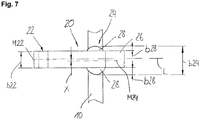
- Fig. 7 shows a further preferred embodiment of a trailing arm 20 in a plan view.
- the trailing arm 20 has a frame-side arrangement section 22 and an axle tube-side arrangement section 24.
- At the achsrohr facilityen arrangement portion 24 is arranged on each side of a respective projection 28, wherein the widths b28 of the projections 28 are formed differently.
- a center line M24 of the tube side arrangement section 24 is oriented by an offset x shifted to a center line M22 of the frame side arrangement section 22. It is understood that projections 28 of different widths can also be combined with trailing arms 20, which already have the offset x between the frame-side arrangement section 22 and the axle tube-side arrangement section 24.
- the offset x is realized via the differently wide projections 28.
- the two arrangement sections would be approximately the same width due to the longitudinal trailing arm shape constant.
- a width b24 of the axis-side arrangement section 24 can now be wider than a width b22 of the frame-side arrangement section.
Description
Die vorliegende Erfindung betrifft einen Längslenker zur Anbindung eines Achsrohrs an einen Fahrzeugrahmen sowie ein Fahrzeugachssystem, insbesondere für ein Nutzfahrzeug.The present invention relates to a trailing arm for connecting an axle tube to a vehicle frame and a Fahrzeugachssystem, in particular for a commercial vehicle.
Längslenker der in Rede stehenden Art sind aus dem Stand der Technik bekannt. Sie kommen z. B. in Starrachs- oder in Lenkachssystemen von Nutzfahrzeugen zum Einsatz. Sie dienen der Anbindung eines Achsrohrs an ein Fahrzeug bzw. an einen Fahrzeugrahmen und gewährleisten eine seitliche Führung des Achsrohrs. Zudem sind sie Teil des Feder- und Dämpfungssystems des Fahrwerks und weisen als solche entsprechende Anbindungsmöglichkeiten für Feder- bzw. Dämpferelemente auf. Die bekannten Längslenker haben allerdings den Nachteil, dass sie sehr groß und schwer bauen, da hohe Kräfte übertragen werden müssen. Dies beengt die knappen Platzverhältnisse unterhalb des Fahrzeugs bzw. unterhalb des Fahrzeugrahmens zusätzlich. Eine optimale Anbindung Längslenker an das Achsrohr bzw. der Längslenker an den Fahrzeugrahmen ist dadurch oft nicht möglich. Zusätzlich gibt es meist Einschränkungen hinsichtlich der Verwendung von Breitreifen, großer Trommelbremsen oder auch großer Scheibenbremsen, da die bekannten Längslenker zu breit bauen. Bei Verwendung in Lenkachssystemen sind damit einhergehend auch oftmals die realisierbaren Lenkeinschläge kleiner als gewünscht.Trailing arms of the type in question are known from the prior art. They come z. B. in Starrachs- or in steering axle systems of commercial vehicles for use. They serve to connect an axle tube to a vehicle or to a vehicle frame and ensure lateral guidance of the axle tube. In addition, they are part of the suspension and damping system of the chassis and have as such appropriate connection options for spring or damper elements. The known trailing arm, however, have the disadvantage that they build very large and heavy, since high forces must be transmitted. This narrows the tight space below the vehicle or below the vehicle frame in addition. An optimal connection trailing arm to the axle tube and the trailing arm to the vehicle frame is often not possible. In addition, there are usually restrictions on the use of wide tires, large drum brakes or large disc brakes, as the known trailing arms build too wide. When used in steering systems, the realizable steering angles are often smaller than desired.
Die
Diese Aufgabe wird gelöst durch einen Längslenker zur Anbindung eines Achsrohrs an einen Fahrzeugrahmen gemäß Anspruch 1 sowie durch ein Fahrzeugachssystem gemäß Anspruch 8. Weitere Vorteile und Merkmale der Erfindung ergeben sich aus den Unteransprüchen und den beigefügten Figuren.This object is achieved by a trailing arm for connecting an axle tube to a vehicle frame according to claim 1 and by a Fahrzeugachssystem according to claim 8. Further advantages and features of the invention will become apparent from the dependent claims and the accompanying figures.
Erfindungsgemäß ist ein Längslenker vorgesehen zur Anbindung eines Achsrohrs an einen Fahrzeugrahmen, welcher sich entlang einer Längsrichtung erstreckt und einen rahmenseitigen Anordnungsabschnitt und zumindest einen achsrohrseitigen Anordnungsabschnitt aufweist, wobei eine Mittellinie des achsrohrseitigen Anordnungsabschnitts quer zur Längsrichtung gesehen zu einer Mittellinie des rahmenseitigen Anordnungsabschnitts um einen Versatz verlagert ist, wobei der Längslenker zumindest bereichsweise als Hohlprofil ausgebildet ist, wobei der Längslenker ein Trägeroberteil und ein Trägerunterteil aufweist, wobei das Trägeroberteil und/oder das Trägerunterteil je einen achsrohrseitigen Anordnungsabschnitt aufweisen, wobei das Trägeroberteil und das Trägerunterteil eine Teilungsebene bilden, welche in einem Winkel zur horizontale Ebene steht, wobei der oder die achsrohrseitigen Anordnungsabschnitte einen Umschlingungswinkel < 180° aufweisen. Es versteht sich, dass der Längslenker auch an Anhängern, Trailern etc. verwendbar ist. Achsen bzw. Starrachsen für Nutzungsfahrzeuge (wie auch für Anhänger, Trailer etc.), sowohl gelenkt als auch ungelenkt, umfassen in der Regel ein Achsrohr, das an beiden Enden einen Achsstummel aufweist. An den Achsstummeln wiederum können z. B. das Bremssystem und die Reifen etc. angeordnet werden. Eine derartige Achse ist in der Regel über zwei Längslenker (manchmal auch Funktionslenker genannt) mit dem Fahrzeugrahmen bzw. mit dem Chassis schwenkbar verbunden. Die Längslenker sind im Wesentlichen entlang der Fahrtrichtung orientiert. Die Längsrichtung entspricht also im Wesentlichen der Fahrtrichtung. Das Achsrohr ist im Wesentlichen quer oder rechtwinklig zu den Längslenkern bzw. der Fahrtrichtung an den Längslenkern bzw. in diesen angeordnet. Achsrohr und Längslenker können direkt miteinander verbunden, beispielsweise verschweißt, werden. Alternativ bevorzugt ist zwischen dem Längslenker und dem Achsrohr auch eine Schale (auch Wrap genannt) angeordnet, die insbesondere den Wärmeeintrag beim Verweißen in das Achsrohr reduzieren kann. Für die Anordnung am Rahmen bzw. am Fahrzeug weist der Längslenker den rahmenseitigen Anordnungsabschnitt auf, für die Anordnung am Achsrohr bzw. für die Anordnung des Achsrohrs den achsrohrseitigen Anordnungsabschnitt. Die genannte Schale kann beispielsweise am achsrohrseitigen Anordnungsabschnitt bzw. innerhalb dessen angeordnet sein. Der rahmenseitige Anordnungsabschnitt und der achsrohrseitige Anordnungsabschnitt weisen zueinander einen Abstand auf, wobei der Abstand im Wesentlichen die Entfernung von Drehpunkten bzw. Mittelpunkten der Anordnungsabschnitte bezeichnet. Abhängig von der Einbaulage des Längslenkers verläuft der Abstand im Wesentlichen etwa parallel zu einer horizontalen Ebene, also zur Fahrbahnebene. Er kann aber auch schräg verlaufen. Dies gilt in gleicher Weise für die Längsrichtung, welche im Wesentlichen entlang des Abstands verläuft. Quer zur Längsrichtung weisen der rahmenseitige Anordnungsabschnitt und der achsohrseitige Anordnungsabschnitt jeweils eine Breite auf. Bevorzugt ist der rahmenseitige Anordnungsabschnitt durch eine runde im Wesentlichen kreisrunde Öffnung gebildet, welche sich im Wesentlichen quer zur Längsrichtung erstreckt. Bevorzugt ist die Öffnung im Querschnitt auch gerade nicht rund, sondern z. B. oval, polygonförmig und/oder eckig. So werden in den rahmenseitigen Anordnungsabschnitten bevorzugt Gummilager oder dergleichen eingesetzt, welche in der Regel im Wesentlichen mittig ein rundes Loch zum Durchstecken einer Achse oder dergleichen aufweisen. Vorteilhafterweise ist eine Außenkontur der Gummilager gerade nicht rund bzw. kreisrund, um ein Verdrehen im rahmenseitigen Anordnungsabschnitt zu verhindern. Der rahmenseitige Anordnungsabschnitt kann mit Vorteil also z. B. auch oval oder polygonförmig ausgebildet sein. Quer zur Längsrichtung weist der rahmenseitige Anordnungsabschnitt bzw. dessen Innenkontur die Breite auf, welche bevorzugt im Wesentlichen konstant ist. Die Mittellinie des rahmenseitigen Anordnungsabschnitts schneidet die Kontur im Wesentlichen mittig bzw. achssymmetrisch. Ähnliches gilt für den achsrohrseitigen Anordnungsabschnitt, welcher ebenfalls bevorzugt eine Öffnung darstellt, welche sich im Wesentlichen quer zur Längsrichtung mit der Breite erstreckt. Bevorzugt ist die Öffnung im Wesentlichen rund oder insbesondere auch kreisrund. Alternativ ist die Öffnung auch oval, polygonförmig und/oder eckig. Die Mittellinie des achsrohrseitigen Anordnungsabschnitts teilt die Breite im Wesentlichen mittig oder achssymmetrisch. Die Mittellinien sowohl des rahmenseitigen Anordnungsabschnitts als auch des achsrohrseitigen Anordnungsabschnitts verlaufen im Wesentlichen parallel zur Längsrichtung und sind um den Versatz verlagert. Zweckmäßigerweise liegt der Versatz in einem Bereich von 10 mm bis 200 mm, bevorzugt in einem Bereich von 30 mm bis 150 mm, ganz bevorzugt in einem Bereich von etwa 40 mm bis 100 mm. Zweckmäßigerweise liegt ein Verhältnis des Versatzes zu dem Abstand zwischen dem achsrohrseitigen und dem rahmenseitigen Anordnungsabschnitt in einem Bereich von etwa 0,01 bis 0,4, bevorzugt etwa in einem Bereich von 0,04 bis 0,3, ganz bevorzugt in einem Bereich von etwa 0,05 bis 0,2. Bevorzugt liegen also der rahmenseitige Anordnungsabschnitt und der achsrohrseitige Anordnungsabschnitt entlang der Längsrichtung bzw. der Fahrtrichtung gesehen nicht auf einer Linie bzw. nicht in einer Flucht. Vorteilhafterweise kann der Längslenker durch den Versatz anderen Gegenständen sozusagen ausweichen. Zweckmäßigerweise ist der Versatz durch unterschiedliche Breiten des achsrohrseitigen und des rahmenseitigen Anordnungsabschnitts erzielbar. Der Längslenker kann in diesem Fall entlang der Längsrichtung im Wesentlichen eine gleiche Breite aufweisen, wobei sozusagen nur die Anordnungsabschnitte zueinander verlagert oder versetzt sind bzw. auch nur deren Mittellinien. Alternativ bevorzugt sind der rahmenseitige und der achsrohrseitige Anordnungsabschnitt auch gleich breit, wobei dann die Form des Längslenkers entlang der Längsrichtung den Versatz bestimmt. Beispielsweise nimmt der Längslenker in einer Draufsicht (im eingebauten Zustand auf die Fahrbahnebene gesehen) in etwa eine S-Form ein. Mit Vorteil kann eine derartige S-Form natürlich auch mit unterschiedlich breiten Anordnungsabschnitten kombiniert werden. Vorteilhafterweise ist damit eine äußerst flexible Anpassung an die Platzverhältnisse unterhalb des Fahrzeugs gegeben. Neben der Raumausnutzung sind durch den oder die Längslenker auch die Kraftflüsse optimierbar. Ebenfalls bevorzugt ermöglicht der Längslenker nämlich eine unterschiedliche Abstützweite am Fahrzeug und am Achsrohr. Dabei definiert der Begriff Abstützweite die Entfernung von zwei entsprechenden Anordnungsabschnitten (rahmenseitig und/oder achsrohrseitig) zweier nebeneinander angeordneter Längslenker quer zur Längsrichtung. Mit Vorteil sind durch den Versatz also unterschiedliche Abstützweiten erzielbar. Die Entfernung zweier rahmenseitiger Anordnungsabschnitte ist also mit Vorteil nicht die Gleiche wie die der achsrohrseitigen Anordnungsabschnitte. Mit Vorteil ist die Abstützweite am Fahrzeug größer als die Abstützweite am Achsrohr, alternativ bevorzugt auch umgekehrt. Die breite Abstützung am Fahrzeug ermöglicht eine äußerst stabile Lagerung des gesamten Aufbaus. Von großem Vorteil ist es also, wenn die Mittellinie des achsrohrseitigen Anordnungsabschnitts gegenüber der Mittellinie des rahmenseitigen Anordnungsabschnitts zu einer Fahrwerks- bzw. Fahrzeugmittellinie hin um den Versatz verlagert ist. Damit wird eine größtmögliche Abstützung der Längslenker am Fahrzeug bei gleichzeitigem Bauraumgewinn, beispielsweise für Breitreifen, geschaffen. Bei Verwendung in einer Lenkachsausführung ist neben der breiten Abstützung am Fahrzeug und dem möglichen Einsatz einer breiten Bereifung zusätzlich ein weitaus größerer Lenkeinschlag bzw. Lenkwinkel möglich. Der zusätzlich auf der Außenseite gewonnene Bauraum kommt dabei nicht nur einer breiteren Bereifung zugute, sondern kann auch dazu genutzt werden, um größer bzw. breiter bauende Trommelbremsen oder länger bauende Scheibenbremsen leichter zu adaptieren bzw. deren Montage zu erleichtern. Es versteht sich, dass es auch möglich ist, zwei Längslenker, welche den Versatz aufweisen, derart anzuordnen, dass die Abstützweite am Fahrzeug die Gleiche ist wie am Achsrohr. Der Längslenker ist zumindest bereichsweise als Hohlprofil ausgebildet, wobei das Hohlprofil vorzugsweise einen Querschnitt aufweist, welcher in Richtung des rahmenseitigen Anordnungsabschnitts zumindest bereichsweise zunimmt. Bevorzugt ist das Hohlprofil ein aus Einzelteilen zusammengeschweißtes Kastenprofil. Besonders bevorzugt ist das Hohlprofil aber mit einem Innenhochdruckumformverfahren (IHU) hergestellt. Mit Vorteil nimmt der Querschnitt des Hohlprofils zumindest abschnittsweise in Richtung des rahmenseitigen Anordnungsabschnitts zu. Bevorzugt ist dadurch eine sehr steife Gestaltung des rahmenseitigen Anordnungsabschnitts möglich. Der Längslenker ist mit Vorteil derart geformt, dass er ein schmutzabweisendes Design aufweist, in dem keine Hinterschnitte, Muldenbildungen und Vertiefungen etc. ausgeführt sind, wodurch die Möglichkeit gegeben ist, einer schädigenden Schmutzablagerung durch Steine, Staub und Salzwasser vorzubeugen. Ein weiterer Vorteil einer übergangsfreien und in sich geschlossenen Längslenkerform ist eine widerstandsarme, stromlinienförmige Gestaltung, die einer extremen Luftverwirbelung unter dem Fahrzeug entgegenwirkt. Bevorzugt ist durch das IHU-Verfahren die Wanddicke flexibel auf die zu erwartende Traglast des Längslenkers abstimmbar. Ebenfalls bevorzugt kann der Längslenker auch als Fachwerk ausgebildet sein. Auch durch die Verwendung einer Fachwerkstruktur kann eine optimale Ausrichtung anhand der auftretenden Kräfte ermöglicht werden. Von großem Vorteil ist es dabei, eine derartige Fachwerkstruktur mit dem Versatz zwischen den Mittellinien des rahmenseitigen und des achsrohrseitigen Anordnungsabschnitts zu kombinieren. In der Kombination ist damit eine sehr leichte, steife und äußerst flexible Ausgestaltung des Längslenkers möglich. Besonders bevorzugt ist zudem die Kombination des Versatzes mit einem mittels eines IHU-Verfahrens gefertigten Längslenkers.According to the invention, a trailing arm is provided for connecting an axle tube to a vehicle frame which extends along a longitudinal direction and has a frame-side locating portion and at least one axle tube-side locating portion, wherein a center line of the axle tube-side locating portion displaces transversely to the longitudinal direction toward a center line of the frame-side locating portion by an offset wherein the trailing arm is at least partially formed as a hollow profile, wherein the trailing arm has a carrier top and a carrier base, wherein the carrier upper part and / or the carrier base each have a Achsrohrseitigen arrangement portion, wherein the carrier upper part and the lower carrier part form a dividing plane, which at an angle to the horizontal plane, wherein the one or more axle tube side arrangement sections have a wrap angle <180 °. It is understood that the trailing arm can also be used on trailers, trailers, etc. Axles or rigid axles for utility vehicles (as well as for trailers, trailers, etc.), both steered and unguided, usually comprise an axle tube which has a stub axle at both ends. In turn, at the stub axles z. B. the brake system and the tires etc. are arranged. Such an axle is usually connected via two trailing arms (sometimes called function link) with the vehicle frame or with the chassis pivotally connected. The trailing arms are oriented substantially along the direction of travel. The longitudinal direction thus corresponds essentially to the direction of travel. The axle tube is arranged substantially transversely or at right angles to the trailing arms or the direction of travel on the trailing arms or in these. Axle tube and trailing arm can be directly connected to each other, for example, welded, be. Alternatively preferably, a shell (also called a wrap) is arranged between the trailing arm and the axle tube, which in particular can reduce the heat input during welding into the axle tube. For the arrangement on the frame or on the vehicle, the trailing arm has the frame-side arrangement section, for the arrangement on the axle tube or for the arrangement of the axle tube, the axle tube-side arrangement section. Said shell can be arranged, for example, on the axle tube side arrangement section or within it. The frame-side arrangement section and the axle tube-side arrangement section are spaced apart from one another, wherein the spacing essentially denotes the distance of pivot points or centers of the arrangement sections. Depending on the mounting position of the trailing arm, the distance is substantially parallel to a horizontal plane, ie to the road surface. He can also run diagonally. This applies equally to the longitudinal direction, which runs essentially along the distance. Transverse to the longitudinal direction, the frame-side arrangement portion and the axis-side arrangement portion each have a width. Preferably, the frame-side arrangement portion is formed by a round substantially circular opening, which extends substantially transversely to the longitudinal direction. Preferably, the opening in the cross section is not straight around, but z. B. oval, polygonal and / or angular. Thus, in the frame-side arrangement portions preferably rubber bearings or the like are used, which generally have a round hole in the middle of the center for inserting an axis or the like. Advantageously, an outer contour of the rubber bearing just not round or circular to prevent twisting in the frame-side arrangement portion. The frame-side arrangement portion can with advantage so z. B. also oval or be formed polygonal. Transverse to the longitudinal direction of the frame-side arrangement portion or its inner contour has the width, which is preferably substantially constant. The center line of the frame-side arrangement section intersects the contour substantially centrally or axisymmetrically. The same applies to the axle tube side arrangement section, which also preferably represents an opening which extends substantially transversely to the longitudinal direction with the width. Preferably, the opening is substantially round or in particular circular. Alternatively, the opening is also oval, polygonal and / or angular. The centerline of the axle tube side arrangement section divides the width substantially centrally or axisymmetrically. The center lines of both the frame-side arrangement portion and the axle tube-side arrangement portion are substantially parallel to the longitudinal direction and displaced by the offset. Conveniently, the offset is in a range of 10 mm to 200 mm, preferably in a range of 30 mm to 150 mm, more preferably in a range of about 40 mm to 100 mm. Conveniently, a ratio of the offset to the distance between the axle tube side and the frame side disposition section is in a range of about 0.01 to 0.4, preferably in a range of 0.04 to 0.3, more preferably in a range of about 0.05 to 0.2. Thus, the frame-side locating portion and the achsrohrseitige locating portion are preferably not along a line or not in alignment as seen along the longitudinal direction or the direction of travel. Advantageously, the trailing arm by the offset other objects so to speak dodge. Conveniently, the offset is achieved by different widths of the axle tube side and the frame-side arrangement portion. In this case, the trailing arm can have substantially the same width along the longitudinal direction, so to speak, only the arrangement sections being displaced from one another or offset, or even only their center lines. Alternatively preferably, the frame-side and the axle tube-side arrangement portion are also the same width, in which case determines the shape of the trailing arm along the longitudinal direction of the offset. For example, the trailing arm takes in a plan view (seen in the installed state on the road plane) in about an S-shape. Of course, such an S-shape can of course also be combined with differently wide arrangement sections become. Advantageously, this is an extremely flexible adaptation to the space available below the vehicle. In addition to the space utilization by the trailing arm or the power flows can be optimized. Also preferably allows the trailing arm namely a different support width on the vehicle and the axle tube. In this case, the term supporting distance defines the distance of two corresponding arrangement sections (on the frame side and / or axle tube side) of two adjacently arranged trailing arms transversely to the longitudinal direction. Advantageously, therefore, different support widths can be achieved by the offset. The removal of two frame-side arrangement sections is therefore advantageously not the same as that of the axle tube-side arrangement sections. Advantageously, the Abstützweite the vehicle is greater than the Abstützweite the axle tube, alternatively preferably also vice versa. The wide support on the vehicle allows extremely stable storage of the entire body. It is thus of great advantage if the center line of the axle tube-side arrangement section is displaced by the offset from the center line of the frame-side arrangement section to a chassis centerline. This is the greatest possible support of the trailing arm on the vehicle with simultaneous space gain, for example, for wide tires, created. When used in a Lenkachsausführung in addition to the wide support on the vehicle and the possible use of a wide tires in addition a much larger steering angle or steering angle possible. The additionally gained on the outside space here not only benefits a wider tires, but can also be used to more easily or broader drum brakes or longer-built disc brakes easier to adapt or facilitate their installation. It is understood that it is also possible to arrange two trailing arms, which have the offset, such that the support width on the vehicle is the same as on the axle tube. The trailing arm is at least partially formed as a hollow profile, wherein the hollow profile preferably has a cross-section which increases at least in regions in the direction of the frame-side arrangement portion. The hollow profile is preferably a box profile welded together from individual parts. Particularly preferred is the hollow profile but with a hydroforming process (IHU) produced. Advantageously, the cross-section of the hollow profile increases at least in sections in the direction of the frame-side arrangement section. Preferably, this makes possible a very rigid design of the frame-side arrangement section. The trailing arm is advantageously shaped such that it has a dirt-repellent design, in which no undercuts, troughs and depressions, etc. are executed, whereby the possibility is given to prevent harmful dirt accumulation by stones, dust and salt water. Another advantage of a transition-free and self-contained trailing arm shape is a low-resistance, streamlined design that counteracts extreme air turbulence under the vehicle. Preferably, the wall thickness is flexibly tuned to the expected load of the trailing arm by the hydroforming process. Also preferably, the trailing arm can be designed as a framework. Also, by using a truss structure optimal alignment based on the forces occurring can be made possible. It is of great advantage in this case to combine such a truss structure with the offset between the center lines of the frame-side and the axle tube-side arrangement section. In combination, a very light, stiff and extremely flexible design of the trailing arm is possible. In addition, the combination of the offset with a trailing arm manufactured by means of an hydroforming process is particularly preferred.
Mit Vorteil weist der Längslenker quer zu einer horizontalen Ebene eine Wölbung auf, wobei sich die Wölbung bevorzugt zwischen dem achsrohrseitigen und dem rahmenseitigen Anordnungsabschnitt erstreckt. Die horizontale Ebene entspricht dabei zweckmäßigerweise einer Ebene, auf der die Schwenkachse des rahmenseitigen Anordnungsabschnitts und die Mittelachse des achsrohrseitigen Anordnungsabschnitts liegen, und insbesondere im Wesentlichen der Fahrbahnebene. Mit Vorteil erstreckt sich die Wölbung auf den gesamten Längslenker bzw. auf dessen gesamten Querschnitt, also nicht nur beispielsweise auf eine Oberkante des Längslenkers. Mit großem Vorteil bildet nämlich die Wölbung sozusagen einen Freiraum unter sich bzw. zwischen dem rahmenseitigen und dem achsrohrseitigen Anordnungsabschnitt. Die Wölbung dient also dazu, den rahmenseitigen und den achsrohrseitigen Anordnungsabschnitt nicht direkt, also auf kürzestem Wege gerade zu verbinden, sondern sozusagen in einem Bogen, wobei sich der Bogen bzw. die Wölbung zwischen dem achsrohrseitigen und dem rahmenseitigen Anordnungsabschnitt erstreckt. Bevorzugt erstreckt sich der Bogen bzw. die Wölbung von der horizontalen Ebene weg. Damit ist zum einen eine sehr hohe Bodenfreiheit erzielbar, zum anderen wird damit zusätzlicher Platz für andere Aggregate unterhalb des Fahrzeugs geschaffen. Alternativ bevorzugt können die genannten Vorteile und Merkmale aber auch dadurch realisiert werden, dass sich der Bogen bzw. die Wölbung gerade zur horizontalen Ebene hin erstreckt. Unter Umständen wird damit zwar die Bodenfreiheit reduziert, es kann aber der Einfederweg deutlich erhöht werden, da der Platzbedarf des Längslenkers nach oben minimal ist. Die tatsächliche Ausgestaltung der Wölbung wird daher vorteilhafterweise vom Einsatzzweck bzw. Einsatzort des jeweiligen Fahrzeugs abhängen. Es versteht sich, dass sich der Bogen nicht durchgängig zwischen dem achsrohrseitigen und dem rahmenseitigen Anordnungsabschnitt erstrecken muss. Beispielsweise kann auch nur ein Abschnitt des Längslenkers zwischen dem rahmenseitigen Anordnungsabschnitt und dem achsrohrseitigen Anordnungsabschnitt im Wesentlichen quer zur horizontalen Ebene nach oben oder nach unten ausgestellt sein, um zusätzlichen Bauraum zwischen den beiden Anordnungsabschnitten zu schaffen. Vorteilhafterweise weist die Wölbung bzw. der Bogen eine maximale Erstreckung im Wesentlichen quer zur horizontalen Ebene ausgehend von dem Drehpunkt des rahmenseitigen Anordnungsabschnitts auf, welche bevorzugt in einem Bereich von etwa 50 mm bis 200 mm liegt. Die Erstreckung bemisst sich dabei lotrecht zum Abstand der Drehpunkte bzw. Mittelpunkte des rahmenseitigen und des achsrohrseitigen Anordnungsabschnitts. Bevorzugt liegt ein Verhältnis der Erstreckung zum Abstand der beiden Anordnungsabschnitte in einem Bereich von etwa 0,1 bis 0,5, besonders bevorzugt in einem Bereich von etwa 0,2 bis 0,3.Advantageously, the trailing arm has a curvature transverse to a horizontal plane, wherein the curvature preferably extends between the axle tube side and the frame-side locating portion. The horizontal plane expediently corresponds to a plane on which the pivot axis of the frame-side arrangement section and the center axis of the axle tube-side arrangement section lie, and in particular essentially the road plane. Advantageously, the curvature extends to the entire trailing arm or to its entire cross section, ie not only for example on an upper edge of the trailing arm. Namely, with great advantage, the curvature forms, as it were, a free space below or between the frame-side and the axle tube-side arrangement section. The curvature thus serves not the frame-side and the axle tube side arrangement section directly, so by the shortest route straight to connect, but in an arc, so to speak, wherein the arc or the curvature between the axle tube side and the frame-side arrangement portion extends. Preferably, the arch or buckle extends away from the horizontal plane. For a very high ground clearance is achieved on the one hand, on the other hand so that additional space for other units below the vehicle is created. Alternatively, however, the stated advantages and features can also be realized in that the arc or the curvature extends straight to the horizontal plane. Under certain circumstances, although the ground clearance is reduced, but it can be significantly increased the compression travel, since the space requirement of the trailing arm is minimal upwards. The actual configuration of the curvature will therefore depend advantageously on the intended use or location of use of the respective vehicle. It is understood that the arc need not extend continuously between the axle tube side and the frame side attachment portion. For example, only a portion of the trailing arm between the frame-side disposition portion and the axle tube-side disposition portion may be extended substantially transversely to the horizontal plane upwards or downwards to provide additional space between the two disposition portions. Advantageously, the curvature or the arc has a maximum extent substantially transversely to the horizontal plane, starting from the pivot point of the frame-side locating portion, which preferably lies in a range of about 50 mm to 200 mm. The extent is measured perpendicular to the distance of the pivot points or centers of the frame-side and the axle tube side arrangement section. Preferably, a ratio of the extent to the spacing of the two arrangement sections lies in a range of about 0.1 to 0.5, particularly preferably in a range of about 0.2 to 0.3.
Weiter weist der Längslenker ein Trägeroberteil und ein Trägerunterteil auf, wobei das Trägeroberteil und das Trägerunterteil, insbesondere deren Trennfläche bzw. Kontaktfläche, eine Teilungsebene bilden, welche in einem Winkel zur horizontalen Ebene steht. Mit Vorteil verläuft die Teilungsebene durch den achsrohrseitigen Anordnungsabschnitt. Besonders bevorzugt auch durch den Drehpunkt bzw. Mittelpunkt des achsohrseitigen Anordnungsabschnitts. Bevorzugt schneidet also die Teilungsebene den achsrohrseitigen Anordnungsabschnitt. Mit anderen Worten ist der Längslenker also im Bereich des achsrohrseitigen Anordnungsabschnitts geteilt. Vorteilhafterweise beträgt der Winkel zwischen der Teilungsebene und der horizontalen Ebene in einer bevorzugten Ausführungsform in etwa 180°. Die Teilungsebene steht also im Wesentlichen bevorzugt parallel zur horizontalen Ebene bzw. zur Fahrbahnebene. Dies ist besonderes vorteilhaft für den Kraftfluss vom Längslenker auf das Achsrohr und in diesem Zusammenhang für die Verbindung mit dem Achsrohr. Das Trägeroberteil und das Trägerunterteil müssen dabei nicht zwingend miteinander verbunden sein. Beide können beispielsweise mit dem Achsrohr form- und/oder kraftschlüssig verbunden sein, ohne sich dabei zu berühren. Vorteilhafterweise sind aber das Trägeroberteil und das Trägerunterteil über zumindest eine Kontaktfläche miteinander verbunden. Bevorzugt liegt die Kontaktfläche innerhalb der Teilungsebene bzw. ist ein Teil derer. Erfindungsgemäß weisen das Trägeroberteil und/oder das Trägerunterteil je einen achsrohrseitigen Anordnungsabschnitt auf, wobei der oder die achsrohrseitigen Anordnungsabschnitte einen Umschlingungswinkel < 180° aufweisen. Mit Vorteil wird also der achsrohrseitige Anordnungsabschnitt des Längslenkers durch die achsrohrseitigen Anordnungsabschnitte des Trägeroberteils und des Trägerunterteils gebildet. Es gelten sämtliche bereits genannten Vorteile und Merkmale bezüglich der Anordnungsabschnitte. Die Aufteilung in das Trägeroberteil und das Trägerunterteil bzw. die Verwendung von zumindest zwei achsrohrseitigen Anordnungsabschnitten ermöglicht mit Vorteil, dass z. B. der achsrohrseitige Anordnungsabschnitt des Trägeroberteils breiter ausgeführt ist als der des Unterteils bzw. umgekehrt. Zweckmäßigerweise ist damit der Kraftfluss optimierbar. Ein großer Vorteil eines Umschlingungswinkels < 180° ist, dass das Achsrohr nicht in den Längslenker geschoben werden muss, sondern dass der Längslenker bzw. die Trägeroberteile oder die Trägerunterteile auf das Achsrohr aufgesetzt werden können. Es versteht sich, dass auch ein Längslenker, welcher nicht aus einem Trägeroberteil und einem Trägerunterteil gebildet ist, einen Umschlingungswinkel < 180° aufweisen kann. Vorteilhafterweise ist aber durch die Verwendung des Trägeroberteils, welche jeweils beide einen Umschlingungswinkel < 180° aufweisen, in Summe wieder ein Umschlingungswinkel erzielbar, welcher > 180° ist.Next, the trailing arm on a carrier shell and a lower carrier part, wherein the upper carrier part and the lower carrier part, in particular their separation surface or contact surface, form a dividing plane, which is at an angle to the horizontal plane. Advantageously, the dividing plane extends through the axle tube side arrangement section. Particularly preferred also by the fulcrum or center of the achsohrseitigen arrangement section. Thus, the dividing plane preferably cuts the axle tube-side arrangement section. In other words, the trailing arm is thus divided in the region of the axle tube side arrangement section. Advantageously, the angle between the dividing plane and the horizontal plane in a preferred embodiment is approximately 180 °. The dividing plane is thus essentially preferably parallel to the horizontal plane or to the roadway plane. This is particularly advantageous for the power flow from the trailing arm to the axle tube and in this connection for the connection to the axle tube. The carrier upper part and the lower carrier part need not necessarily be connected to each other. Both can be positively and / or non-positively connected to the axle tube, for example, without touching each other. Advantageously, however, the carrier upper part and the lower carrier part are connected to one another via at least one contact surface. Preferably, the contact surface is within the division plane or is a part of them. According to the invention, the carrier upper part and / or the lower carrier part each have an axle tube side arrangement section, wherein the one or more axle tube side arrangement sections have a wrap angle <180 °. Advantageously, therefore, the axle tube-side arrangement section of the trailing arm is formed by the axle tube-side arrangement sections of the carrier upper part and of the carrier lower part. All the advantages and features already mentioned regarding the arrangement sections apply. The division into the carrier upper part and the lower carrier part or the use of at least two axle tube side arrangement sections allows advantageously that z. B. the achsrohrseitige arrangement portion of the carrier upper part is made wider than that of the lower part or vice versa. Appropriately, so that the power flow can be optimized. A great advantage of a wrap angle <180 ° is that the axle tube does not have to be pushed into the trailing arm, but rather that the trailing arm or the carrier upper parts or the carrier lower parts can be placed on the axle tube. It is understood that a trailing arm, which is not formed from a carrier shell and a carrier base, may have a wrap angle <180 °. Advantageously, however, by the use of Carrier shell, which each have a wrap angle <180 °, in sum, again a wrap angle achievable, which is> 180 °.
Zweckmäßigerweise sind das Trägeroberteil und/oder das Trägerunterteil form- und/oder kraftschlüssig mit einer Adapterplatte verbunden, wobei die Adapterplatte form- und/oder kraftschlüssig mit einer Tragfläche verbunden ist, welche ausgelegt ist für die Anordnung eines Feder-/Dämpferelements. In dieser Variante ist der Längslenker also in Summe sozusagen dreiteilig ausgeführt, wobei die drei Teile über die Adapterplatte miteinander verbunden sind. Es versteht sich, dass der Längslenker auch einteilig ausgebildet sein kann, wobei dann die Tragfläche ein Teil des Längslenkers ist. Ebenfalls mit Vorteil kann die Tragfläche auch ein Teil des Trägerunterteils oder ein Teil des Trägeroberteils sein. Bevorzugt werden das Trägeroberteil, das Trägerunterteil und/oder auch die Tragfläche auf Stoß mit der Adapterplatte verschweißt. Bevorzugt kann die Adapterplatte aber auch eine Öffnung aufweisen, durch welche das Trägerunterteil, das Trägeroberteil und/oder die Tragfläche hindurchragen können, was ein umfängliches Verschweißen (entlang der Außenkontur der genannten Teile) mit der Adapterplatte ermöglicht. An der Adapterplatte ist auch mit großem Vorteil ein Verschrauben der genannten Teile möglich. Auch das Trägeroberteil und das Trägerunterteil können miteinander verschraubt werden. Ebenfalls bevorzugt ermöglicht die Adapterplatte die Kombination unterschiedlicher Werkstoffe. So kann beispielsweise der Längslenker bzw. das Trägeroberteil und/oder das Trägerunterteil aus einem Stahl- oder Aluminiumwerkstoff gefertigt sind, während an der Adapterplatte eine Trägfläche aus einem Komposit- oder Verbundmaterial beispielsweise form- und/oder kraftschlüssig über geeignete Schraubverbindungen anordenbar ist.Conveniently, the carrier shell and / or the carrier base are positively and / or non-positively connected to an adapter plate, wherein the adapter plate is positively and / or non-positively connected to a support surface which is designed for the arrangement of a spring / damper element. In this variant, the trailing arm is therefore designed in three parts, so to speak, in total, wherein the three parts are connected to one another via the adapter plate. It is understood that the trailing arm can also be formed in one piece, in which case the support surface is a part of the trailing arm. Also advantageously, the support surface may also be a part of the carrier base or a part of the carrier shell. Preferably, the upper carrier part, the lower carrier part and / or the support surface are welded to the adapter plate in abutment. However, the adapter plate can preferably also have an opening through which the carrier lower part, the carrier upper part and / or the support surface can protrude, which allows circumferential welding (along the outer contour of said parts) with the adapter plate. On the adapter plate screwing of the said parts is also possible with great advantage. The upper carrier part and the lower carrier part can also be screwed together. Also preferably, the adapter plate allows the combination of different materials. Thus, for example, the trailing arm or the upper carrier part and / or the lower carrier part are made of a steel or aluminum material, while on the adapter plate a support surface made of a composite or composite material, for example, form and / or non-positively can be arranged via suitable screw.
Zweckmäßigerweise weist der Längslenker am achsrohrseitigen Anordnungsabschnitt zur Anbindung des Achsrohrs und/oder der Schale zumindest einen Vorsprung auf, welcher sich im Wesentlichen entlang des Achsrohrs erstreckt. Mit Vorteil weist der Vorsprung den gleichen Umschlingungswinkel wie der Längslenker bzw. das Trägeroberteil oder das Trägerunterteil auf. Es versteht sich, dass umfänglich um das Achsrohr mehr als ein Vorsprung angeordnet werden kann. Außerdem ist eine Anordnung zu beiden Seiten des Längslenkers bzw. des achsrohrseitigen Anordnungsabschnitts möglich. In einer bevorzugten Ausführungsform mit einer Teilungsebene, welche im Wesentlichen parallel zur horizontalen Ebene steht, ist am Trägeroberteil, zu beiden Seiten des Lenkers, bevorzugt ein Vorsprung angeordnet. Der Vorsprung kann beispielsweise am Längslenker bzw. am Trägeroberteil und/oder am Trägerunterteil angeschweißt werden. Mit Vorteil können aber die genannten Bauteile den Vorsprung auch selbst ausbilden. Der Vorsprung muss dann nicht extra angebracht werden. Der Vorsprung weist zum Achsrohr bzw. zur Schale vorteilhafterweise einen Kontaktbereich auf. Mit Vorteil bildet der Kontaktbereich im Wesentlichen einen Linienkontakt und keinen Flächenkontakt. Gleiches gilt für die Anordnung zum Längslenker hin. Auch hier ist mit Vorteil ein Linienkontakt vorgesehen. Der Vorsprung hat zweckmäßigerweise also nicht mit seiner gesamten Breite bzw. mit seiner gesamten Höhe Kontakt mit dem zu verbindenden bzw. angeordneten Bauteil. Aufgrund der äußerst günstigen Krafteinleitung in das Achsrohr kann der Längslenker, der den oder die Vorsprünge aufweist mit Vorteil ohne die Schale mit dem Achsrohr verbunden werden bzw. sein. Es versteht sich, dass der Längslenker auch am rahmenseitigen Anordnungsabschnitt zumindest einen Vorsprung aufweisen kann. Sämtliche Vorteile und Merkmale gelten dabei in gleicher Weise.Expediently, the trailing arm on the axle tube-side arrangement section for connecting the axle tube and / or the shell has at least one projection which extends substantially along the axle tube. Advantageously, the projection has the same wrap angle as the trailing arm or the upper carrier part or the lower carrier part. It is understood that more than one projection can be arranged circumferentially around the axle tube. In addition, an arrangement on both sides of the trailing arm or the axle tube side Arrangement section possible. In a preferred embodiment with a dividing plane which is substantially parallel to the horizontal plane, a projection is preferably arranged on the carrier upper part, on both sides of the link. The projection can be welded, for example, on the trailing arm or on the upper carrier part and / or on the lower carrier part. Advantageously, however, the said components can also form the projection itself. The projection then does not need to be extra attached. The projection advantageously has a contact area to the axle tube or to the shell. Advantageously, the contact area essentially forms a line contact and not a surface contact. The same applies to the arrangement to the trailing arm out. Again, a line contact is provided with advantage. The projection has expediently therefore not with its entire width or with its entire height in contact with the component to be connected or arranged. Due to the extremely favorable introduction of force into the axle tube, the trailing arm, which has the projection or protrusions, can advantageously be connected to the axle tube without the shell. It is understood that the trailing arm can also have at least one projection on the frame-side arrangement section. All advantages and features apply in the same way.
Zweckmäßigerweise verbindet der zumindest eine Vorsprung den Längslenker und das Achsrohr und/oder die Schale in einem Bogen. Mit Vorteil erstreckt sich dabei der Bogen im Wesentlichen quer zur Längsrichtung vom Längslenker zum Achsrohr. Der Bogen kann dabei konvex oder konkav ausgeführt sein. Mit Vorteil ist er derart gestaltet, dass ein Kraftfluss zwischen dem Achsrohr und dem Längslenker optimierbar ist. Mit anderen Worten stellt der Bogen sozusagen eine Verbindung der beiden Linienkontakte dar. Der Bogen ermöglicht eine sehr steife Anbindung des Achsrohrs. Zudem ist durch den Vorsprung sozusagen die Breite des achsrohrseitigen Anordnungsabschnitts vergrößerbar. Die Belastungsspitzen auf das Achsrohr nehmen ab. Außerdem wird der Kraftfluss zwischen dem Längslenker und dem Achsrohr verringert, da der Vorsprung durch den Linienkontakt einen zusätzlichen "Kräftepfad" bereitstellt. An dieser Stelle sei erwähnt, dass es auch möglich wäre, dass die Verbindung zwischen dem Längslenker und dem Achsrohr auch ausschließlich über den bzw. die Vorsprünge möglich ist, dass also der ursprüngliche oder eigentliche achsrohrseitige Anordnungsbereich des Längslenkers gar keinen unmittelbaren Kontakt mehr mit dem Achsrohr aufweist. Vorteilhafterweise erfolgt das Verschweißen des Längslenkers mit dem Achsrohr zumindest bereichsweise entlang des Vorsprungs. Es versteht sich, dass der Vorsprung auch mit der Schale verschweißt werden kann.Conveniently, the at least one projection connects the trailing arm and the axle tube and / or the shell in an arc. Advantageously, the arc extends substantially transversely to the longitudinal direction of the trailing arm to the axle tube. The bow can be made convex or concave. Advantageously, it is designed such that a power flow between the axle tube and the trailing arm can be optimized. In other words, the arc represents, so to speak, a connection of the two line contacts. The arc allows a very rigid connection of the axle tube. In addition, by the projection, so to speak, the width of the axle tube side arrangement portion can be increased. The load peaks on the axle tube decrease. In addition, the power flow between the trailing arm and the axle tube is reduced because the projection provides an additional "force path" through the line contact. At this point it should be mentioned that it would also be possible that the connection between the trailing arm and the axle tube is also possible only via the projections or protrusions, that is, the original one or actual achsrohrseitige arrangement region of the trailing arm has no direct contact with the axle tube. Advantageously, the welding of the trailing arm with the axle tube takes place at least partially along the projection. It is understood that the projection can also be welded to the shell.
Zweckmäßigerweise ist zu beiden Seiten des achsrohrseitigen Anordnungsabschnitts ein Vorsprung angeordnet, wobei die beiden Vorsprünge vorzugsweise eine unterschiedliche Breite aufweisen. Die Breite bemisst sich dabei im Wesentlichen quer zur Längsrichtung und entlang des Achsrohrs. Mit Vorteil ist durch die Verwendung unterschiedlich breiter Vorsprünge der Versatz der Mittellinie des rahmenseitigen Anordnungsabschnitts zur Mittellinie des achsrohrseitigen Anordnungsabschnitts weiter variierbar. Mit Vorteil ist dadurch eine noch flexiblere Ausgestaltung des Längslenkers möglich. Quer zur Längsrichtung und zur Breite des Vorsprungs weist der Vorsprung mit Vorteil eine (maximale) Höhe auf. Zweckmäßigerweise liegt ein Höhen/Breiten-Verhältnis des Vorsprungs in einem Bereich von etwa 0,2 bis 1,8, bevorzugt bei etwa 0,7 bis 1,8, besonders bevorzugt bei etwa 0,8 bis 1,2.Expediently, a projection is arranged on both sides of the axle tube-side arrangement section, wherein the two projections preferably have a different width. The width is measured essentially transversely to the longitudinal direction and along the axle tube. Advantageously, the offset of the center line of the frame-side arrangement section to the center line of the axle tube-side arrangement section can be further varied by using projections of different widths. Advantageously, thereby an even more flexible design of the trailing arm is possible. Transverse to the longitudinal direction and the width of the projection, the projection advantageously has a (maximum) height. Conveniently, a height / width ratio of the protrusion is in a range of about 0.2 to 1.8, preferably about 0.7 to 1.8, more preferably about 0.8 to 1.2.
Erfindungsgemäß ist ein Fahrzeugachssystem, insbesondere für ein Nutzfahrzeug, mit einem Längslenker zur Anbindung eines Achsrohrs an einen Fahrzeugrahmen wie oben beschrieben vorgesehen. Es versteht sich, dass sämtliche Vorteile und Merkmale des erfindungsgemäßen Längslenkers auch für das erfindungsgemäße Fahrzeugachssystem gelten und umgekehrt. Weitere Vorteile und Merkmale ergeben sich aus der nachfolgenden Beschreibung bevorzugter Ausführungsformen des erfindungsgemäßen Längslenkers und des erfindungsgemäßen Fahrzeugachssystems mit Bezug auf die beigefügten Figuren. Einzelne Merkmale der einzelnen Ausführungsformen können dabei im Rahmen der Erfindung miteinander kombiniert werden.According to the invention, a vehicle axle system, in particular for a utility vehicle, is provided with a trailing arm for connecting an axle tube to a vehicle frame as described above. It is understood that all advantages and features of the trailing arm according to the invention also apply to the Fahrzeugachssystem invention and vice versa. Further advantages and features will become apparent from the following description of preferred embodiments of the trailing arm and the Fahrzeugachssystem invention with reference to the accompanying figures. Individual features of the individual embodiments can be combined with each other within the scope of the invention.
Es zeigen:
- Figur 1:
- eine schematische Darstellung einer bevorzugten Ausführungsform eines Längslenkers in einer Draufsicht;
- Figur 2:
- eine schematische Darstellung einer bevorzugten Ausführungsform eines Längslenkers mit Anordnungsabschnitten gleicher Breite und einem Versatz;
- Figur 3:
- eine schematische Darstellung einer bevorzugten Ausführungsform eines Längslenkers in einer Seitenansicht;
- Figur 4:
- eine schematische Darstellung einer bevorzugten Ausführungsform eines Längslenkers in einer Seitenansicht mit einer Schale;
- Figur 5:
- eine schematische Darstellung einer bevorzugten Ausführungsform eines Längslenkers mit einem Trägeroberteil und einem Trägerunterteil;
- Figur 6:
- eine Schnittansicht einer bevorzugten Ausführungsform eines achsrohrseitigen Anordnungsabschnitts;
- Figur 7:
- eine schematische Darstellung einer bevorzugten Ausführungsform eines Längslenkers mit zwei Vorsprüngen in einer Draufsicht.
- FIG. 1:
- a schematic representation of a preferred embodiment of a trailing arm in a plan view;
- FIG. 2:
- a schematic representation of a preferred embodiment of a trailing arm with arrangement sections of equal width and an offset;
- FIG. 3:
- a schematic representation of a preferred embodiment of a trailing arm in a side view;
- FIG. 4:
- a schematic representation of a preferred embodiment of a trailing arm in a side view with a shell;
- FIG. 5:
- a schematic representation of a preferred embodiment of a trailing arm with a carrier shell and a carrier base;
- FIG. 6:
- a sectional view of a preferred embodiment of an axle tube side assembly portion;
- FIG. 7:
- a schematic representation of a preferred embodiment of a trailing arm with two projections in a plan view.
Achsrohr 10 verbunden. Es versteht sich, dass die Vorsprünge 28 auch eine eher konvexe oder gerade Form im Querschnitt darstellen bzw. aufweisen können. Hierbei wird auch deutlich, dass die beiden Vorsprünge 28 keinen Flächen- sondern einen Linienkontakt mit dem Achsrohr 10 bzw. mit dem Trägeroberteil 42 aufweisen. Entlang des Linienkontakts findet mit Vorteil die Verschweißung statt.
- 1010
- Achsrohraxle tube
- 1212
- SchaleBowl
- 2020
- LängslenkerTrailing arm
- 2222
- rahmenseitiger Anordnungsabschnittframe-side arrangement section
- 2424
- achsrohrseitiger AnordnungsabschnittAchsrohrseitiger arrangement section
- 2626
- Tragflächewing
- 2828
- Vorsprunghead Start
- 3030
- Wölbungbulge
- 4242
- TrägeroberteilCami
- 4444
- TrägerunterteilCarrier base
- 4646
- Kontaktflächecontact area
- 6060
- Adapterplatteadapter plate
- D22, D24D22, D24
- Drehpunktefulcrums
- Ee
- horizontale Ebenehorizontal plane
- SS
- SchweißnahtWeld
- TT
- Teilungsebeneparting plane
- LL
- Längsrichtunglongitudinal direction
- M22, M24M22, M24
- Mittelliniencenterlines
- aa
- Erstreckungextension
- b22b22
- Breite des rahmenseitigen AnordnungsabschnittsWidth of the frame-side arrangement section
- b24b24
- Breite des achsrohrseitigen AnordnungsabschnittsWidth of the axle tube side arrangement section
- b28b28
- Breite des VorsprungsWidth of the projection
- h28h28
- Höhe des VorsprungsHeight of the projection
- xx
- Versatzoffset
- ϕφ
- UmschlingungswinkelWrap angle
- αα
- Winkel der EbenenAngle of the levels
Claims (8)
- A longitudinal control arm (20) for connection of an axle tube (10) to a vehicle frame, said longitudinal control arm extending along a longitudinal direction (L) and
comprising an arrangement section (22) on the frame side and at least one arrangement section (24) on the axle tube side,
wherein a centerline (M24) of the arrangement section (24) on the axle tube side is offset or displaced by an offset (x) from a centerline (M22) of the arrangement section (22) on the frame side when seen transverse to the longitudinal direction (L)
wherein the longitudinal control arm (20) is formed as a hollow profile at least in regions,
wherein the longitudinal control arm (20) has an upper support part (42) and a lower support part (44), and
wherein the upper support part (42) and/or the lower support part (44) each has/have an arrangement section (24) on the axle tube side,
wherein the upper support part (42) and the lower support part (44) form a parting plane (T), which is positioned at an angle (α) relative to the horizontal plane (E)
characterized by,
the arrangement section(s) (24) has/have an angle of enlacement (ϕ) < 180°. - The longitudinal control arm of claim 1,
wherein the hollow profile preferably has a cross-section, which increases at least in regions in the direction of the arrangement section (22) on the frame side. - The longitudinal control arm (20) of claim 1 or 2,
wherein the longitudinal control arm (20) has a curvature (30) transverse to a horizontal plane (E),
wherein the curvature preferably extends between the arrangement section (24) on the axle tube side and the arrangement section (22) on the frame side. - The longitudinal control arm (20) of any one of the preceding claims,
wherein the upper support part (42) and/or the lower support part (44) is/are connected to an adapter plate (60) in a form-fitting and/or in a force-fitting manner, and
wherein the adapter plate (60) is in a form-fitting and/or force-fitting manner connected to a bearing surface (26) adapted for the arrangement of a spring/damper element. - The longitudinal control arm (20) of any one of the preceding claims,
wherein, on the arrangement section (24) on the axle tube side, for connecting the axle tube (10) and/or a wrap (12), the longitudinal control arm (20) has at least one projection (28) extending substantially along the axle tube (10). - The longitudinal control arm (20) of claim 5,
wherein the at least one projection (28) connects the longitudinal control arm (20) and the axle tube (10) and/or the wrap (12) in an arc. - The longitudinal control arm (20) of any one of claims 5 or 6,
wherein the projection (28) is arranged on either side of the arrangement section (24) on the axle tube side, and
wherein the two projections (28) preferably have different widths (b). - Vehicle axle system, in particular for a utility vehicle,
having a longitudinal control arm (20) according to any one of claims 1-7.
Applications Claiming Priority (2)
| Application Number | Priority Date | Filing Date | Title |
|---|---|---|---|
| DE102013211468.0A DE102013211468B4 (en) | 2013-06-19 | 2013-06-19 | Trailing arm |
| PCT/EP2014/062642 WO2014202563A1 (en) | 2013-06-19 | 2014-06-17 | Longitudinal control arm |
Publications (2)
| Publication Number | Publication Date |
|---|---|
| EP2986459A1 EP2986459A1 (en) | 2016-02-24 |
| EP2986459B1 true EP2986459B1 (en) | 2018-06-20 |
Family
ID=50972716
Family Applications (1)
| Application Number | Title | Priority Date | Filing Date |
|---|---|---|---|
| EP14730899.3A Active EP2986459B1 (en) | 2013-06-19 | 2014-06-17 | Longitudinal control arm |
Country Status (7)
| Country | Link |
|---|---|
| US (1) | US9662949B2 (en) |
| EP (1) | EP2986459B1 (en) |
| CN (1) | CN105307878B (en) |
| AU (1) | AU2014283417B2 (en) |
| DE (1) | DE102013211468B4 (en) |
| RU (1) | RU2647113C2 (en) |
| WO (1) | WO2014202563A1 (en) |
Families Citing this family (3)
| Publication number | Priority date | Publication date | Assignee | Title |
|---|---|---|---|---|
| DE102013210142A1 (en) * | 2013-05-31 | 2014-12-04 | Saf-Holland Gmbh | handlebar unit |
| DE102015214456A1 (en) * | 2015-07-30 | 2017-02-02 | Deere & Company | Cabin storage arrangement for a commercial vehicle |
| CA3017134A1 (en) * | 2016-03-17 | 2017-09-21 | Saf-Holland, Inc. | Powered vehicle suspension assembly |
Citations (12)
| Publication number | Priority date | Publication date | Assignee | Title |
|---|---|---|---|---|
| EP0367986A1 (en) | 1988-10-08 | 1990-05-16 | FELDBINDER & BECKMANN oHG | Axle suspension for a self-steering semi-trailer rear axle |
| DE3913697A1 (en) | 1989-04-26 | 1990-10-31 | Bergische Achsen Kotz Soehne | AXLE UNIT |
| US5203585A (en) | 1991-07-12 | 1993-04-20 | Neway Corp. | Split-beam suspension system |
| GB2396140A (en) | 2002-12-13 | 2004-06-16 | Meritor Heavy Vehicle Sys Ltd | A cast suspension trailing arm for heavy commercial vehicles |
| EP1671821A1 (en) | 2004-12-17 | 2006-06-21 | ArvinMeritor Technology, LLC | Trailing arm suspension |
| US20060181047A1 (en) | 2005-02-14 | 2006-08-17 | Chamberlin Michael A | Trailing arm for a vehicle suspension |
| DE102005022745A1 (en) | 2005-03-30 | 2006-10-05 | Otto Sauer Achsenfabrik Gmbh | Rigid axle assembly for vehicle is made by passing swinging arm in straight line through opening in axle body and welding them together |
| EP1728654A1 (en) | 2005-06-03 | 2006-12-06 | Meritor Heavy Vehicle Systems Limited | A suspension trailing arm |
| DE19818698B4 (en) | 1997-11-21 | 2010-12-02 | Saf-Holland Gmbh | Suspension for a vehicle axle |
| EP2355988A1 (en) | 2008-12-09 | 2011-08-17 | BPW Bergische Achsen KG | Axle suspension for a vehicle axle |
| EP2397340A2 (en) | 2010-06-16 | 2011-12-21 | Gigant-Trenkamp & Gehle GmbH | Motor vehicle axle |
| CA2727344A1 (en) | 2010-12-23 | 2012-06-23 | Breton, Etienne | Air bag vehicle suspension system |
Family Cites Families (18)
| Publication number | Priority date | Publication date | Assignee | Title |
|---|---|---|---|---|
| US5375871A (en) * | 1993-07-02 | 1994-12-27 | Ridewell Corporation | Vehicle suspension system comprising a wide base beam and axle shell |
| US5690353A (en) * | 1996-05-09 | 1997-11-25 | Suspensions Incorporated | Suspension system with improved beam |
| DE29616257U1 (en) * | 1996-09-19 | 1996-11-07 | Sauer Achsenfab | Suspension for air suspension vehicle wheel axle |
| GB0021716D0 (en) * | 2000-09-05 | 2000-10-18 | Meritor Heavy Vehicle Sys Ltd | Vehicle suspension axle wrap |
| US6834874B1 (en) * | 2002-10-07 | 2004-12-28 | Jerry Overby | Trailer suspension system |
| US6827360B2 (en) * | 2002-10-24 | 2004-12-07 | Arvinmeritor Technology, Llc | One-piece trailing arm section |
| US7347435B2 (en) * | 2005-01-14 | 2008-03-25 | Watson & Chalin Manufacturing, Inc. | Suspension system having reduced weight arm construction |
| DE202005004965U1 (en) * | 2005-03-30 | 2005-05-25 | Otto Sauer Achsenfabrik Gmbh | Rigid axle assembly for vehicle is made by passing swinging arm in straight line through opening in axle body and welding them together |
| DE102006009441B4 (en) * | 2006-03-01 | 2008-09-04 | Saf-Holland Gmbh | Cast-arm with integrated steel bush |
| DE102006015671B4 (en) * | 2006-04-04 | 2020-01-02 | Bpw Bergische Achsen Kg | Vehicle axle body |
| GB0619981D0 (en) * | 2006-10-10 | 2006-11-15 | Meritor Heavy Vehicle Sys Ltd | Suspension sub-assembly |
| NL1034756C1 (en) * | 2007-07-20 | 2009-01-21 | Weweler Nv | Wheel axle suspension for use in vehicle e.g. lorry, has trailing arm for attaching axle of wheel of vehicle, which is wider in contact region formed corresponding to outer contour of axle, and clamped with axle |
| US20090072505A1 (en) * | 2007-09-13 | 2009-03-19 | Tuthill Corporation | Vehicle suspension with trailing arm and axle assembly and method |
| US8764037B2 (en) * | 2009-11-10 | 2014-07-01 | Vdl Weweler B.V. | Wheel axle suspension having clamp bodies with a protrusion for attaching an indented tubular axle to trailing arms |
| US8333396B2 (en) * | 2010-01-05 | 2012-12-18 | Arvinmeritor Technology, Llc | Top mount trailing arm suspension |
| US8998229B2 (en) * | 2011-08-31 | 2015-04-07 | John Michel | I-beam axle suspension system |
| DE102011086480B4 (en) * | 2011-11-16 | 2021-01-28 | Saf-Holland Gmbh | Axle unit for commercial vehicles |
| DE102013214737A1 (en) * | 2013-07-29 | 2015-01-29 | Saf-Holland Gmbh | handlebar unit |
-
2013
- 2013-06-19 DE DE102013211468.0A patent/DE102013211468B4/en active Active
-
2014
- 2014-06-17 EP EP14730899.3A patent/EP2986459B1/en active Active
- 2014-06-17 CN CN201480035027.2A patent/CN105307878B/en active Active
- 2014-06-17 RU RU2015153269A patent/RU2647113C2/en not_active IP Right Cessation
- 2014-06-17 US US14/896,212 patent/US9662949B2/en active Active
- 2014-06-17 AU AU2014283417A patent/AU2014283417B2/en not_active Ceased
- 2014-06-17 WO PCT/EP2014/062642 patent/WO2014202563A1/en active Application Filing
Patent Citations (12)
| Publication number | Priority date | Publication date | Assignee | Title |
|---|---|---|---|---|
| EP0367986A1 (en) | 1988-10-08 | 1990-05-16 | FELDBINDER & BECKMANN oHG | Axle suspension for a self-steering semi-trailer rear axle |
| DE3913697A1 (en) | 1989-04-26 | 1990-10-31 | Bergische Achsen Kotz Soehne | AXLE UNIT |
| US5203585A (en) | 1991-07-12 | 1993-04-20 | Neway Corp. | Split-beam suspension system |
| DE19818698B4 (en) | 1997-11-21 | 2010-12-02 | Saf-Holland Gmbh | Suspension for a vehicle axle |
| GB2396140A (en) | 2002-12-13 | 2004-06-16 | Meritor Heavy Vehicle Sys Ltd | A cast suspension trailing arm for heavy commercial vehicles |
| EP1671821A1 (en) | 2004-12-17 | 2006-06-21 | ArvinMeritor Technology, LLC | Trailing arm suspension |
| US20060181047A1 (en) | 2005-02-14 | 2006-08-17 | Chamberlin Michael A | Trailing arm for a vehicle suspension |
| DE102005022745A1 (en) | 2005-03-30 | 2006-10-05 | Otto Sauer Achsenfabrik Gmbh | Rigid axle assembly for vehicle is made by passing swinging arm in straight line through opening in axle body and welding them together |
| EP1728654A1 (en) | 2005-06-03 | 2006-12-06 | Meritor Heavy Vehicle Systems Limited | A suspension trailing arm |
| EP2355988A1 (en) | 2008-12-09 | 2011-08-17 | BPW Bergische Achsen KG | Axle suspension for a vehicle axle |
| EP2397340A2 (en) | 2010-06-16 | 2011-12-21 | Gigant-Trenkamp & Gehle GmbH | Motor vehicle axle |
| CA2727344A1 (en) | 2010-12-23 | 2012-06-23 | Breton, Etienne | Air bag vehicle suspension system |
Also Published As
| Publication number | Publication date |
|---|---|
| RU2015153269A (en) | 2017-07-20 |
| RU2647113C2 (en) | 2018-03-13 |
| CN105307878A (en) | 2016-02-03 |
| AU2014283417A1 (en) | 2015-12-10 |
| CN105307878B (en) | 2018-01-02 |
| WO2014202563A1 (en) | 2014-12-24 |
| US20160152104A1 (en) | 2016-06-02 |
| AU2014283417B2 (en) | 2016-06-16 |
| DE102013211468A1 (en) | 2014-12-24 |
| DE102013211468B4 (en) | 2017-05-04 |
| US9662949B2 (en) | 2017-05-30 |
| EP2986459A1 (en) | 2016-02-24 |
Similar Documents
| Publication | Publication Date | Title |
|---|---|---|
| EP2607115B2 (en) | Axle suspension for a vehicle axle | |
| DE102013108695B4 (en) | Subframe for a motor vehicle axle | |
| EP2881307B1 (en) | Sub-frame for a vehicle | |
| WO2015018501A1 (en) | Subframe for a motor vehicle | |
| DE102014100618B3 (en) | Motor vehicle axle | |
| DE102009042060A1 (en) | Structural component for the rear frame structure of a motor vehicle | |
| DE202017100162U1 (en) | Handlebar in shell construction for a suspension of a vehicle | |
| EP1777085B1 (en) | Axle suspension for trailing arms carrying a vehicle axle | |
| EP3257691A1 (en) | Commercial vehicle chassis support structure and commercial vehicle chassis | |
| DE102013210142A1 (en) | handlebar unit | |
| EP2114753B1 (en) | Axle bracket for motor vehicles | |
| EP2986459B1 (en) | Longitudinal control arm | |
| EP2994325B1 (en) | Axle connection | |
| EP2772372B1 (en) | Suspension for a commercial vehicle and axle body | |
| DE102016109184B4 (en) | Haltebock | |
| DE3543085A1 (en) | FRAME-LIKE, FLEXIBLE AXLE SUSPENSION SYSTEM | |
| EP3303018B1 (en) | Axle assembly for a vehicle | |
| DE102006060405B3 (en) | Frame arrangement for a vehicle | |
| EP3368395B1 (en) | Wheel suspension arrangement of a steerable wheel of a two-track vehicle | |
| DE102015209351B4 (en) | trailing arm | |
| DE102018006572B4 (en) | Vehicle suspension arrangement for at least one wheel axle | |
| EP2174859A2 (en) | Spacer for enlarging the track and/or lowering of a motor vehicle | |
| DE102018126732A1 (en) | Handlebar for a handlebar system for connecting a wheel carrier to a body of a vehicle | |
| EP3501952A1 (en) | Tolerance compensation in assembled parts in components by means of elastic elements |
Legal Events
| Date | Code | Title | Description |
|---|---|---|---|
| PUAI | Public reference made under article 153(3) epc to a published international application that has entered the european phase |
Free format text: ORIGINAL CODE: 0009012 |
|
| 17P | Request for examination filed |
Effective date: 20151120 |
|
| AK | Designated contracting states |
Kind code of ref document: A1 Designated state(s): AL AT BE BG CH CY CZ DE DK EE ES FI FR GB GR HR HU IE IS IT LI LT LU LV MC MK MT NL NO PL PT RO RS SE SI SK SM TR |
|
| AX | Request for extension of the european patent |
Extension state: BA ME |
|
| RIN1 | Information on inventor provided before grant (corrected) |
Inventor name: SPIELMANN, ROLF Inventor name: HOPPE, MATTHIAS |
|
| DAX | Request for extension of the european patent (deleted) | ||
| GRAJ | Information related to disapproval of communication of intention to grant by the applicant or resumption of examination proceedings by the epo deleted |
Free format text: ORIGINAL CODE: EPIDOSDIGR1 |
|
| STAA | Information on the status of an ep patent application or granted ep patent |
Free format text: STATUS: GRANT OF PATENT IS INTENDED |
|
| GRAP | Despatch of communication of intention to grant a patent |
Free format text: ORIGINAL CODE: EPIDOSNIGR1 |
|
| INTG | Intention to grant announced |
Effective date: 20171129 |
|
| GRAS | Grant fee paid |
Free format text: ORIGINAL CODE: EPIDOSNIGR3 |
|
| GRAJ | Information related to disapproval of communication of intention to grant by the applicant or resumption of examination proceedings by the epo deleted |
Free format text: ORIGINAL CODE: EPIDOSDIGR1 |
|
| GRAL | Information related to payment of fee for publishing/printing deleted |
Free format text: ORIGINAL CODE: EPIDOSDIGR3 |
|
| STAA | Information on the status of an ep patent application or granted ep patent |
Free format text: STATUS: REQUEST FOR EXAMINATION WAS MADE |
|
| INTC | Intention to grant announced (deleted) | ||
| GRAR | Information related to intention to grant a patent recorded |
Free format text: ORIGINAL CODE: EPIDOSNIGR71 |
|
| STAA | Information on the status of an ep patent application or granted ep patent |
Free format text: STATUS: GRANT OF PATENT IS INTENDED |
|
| GRAA | (expected) grant |
Free format text: ORIGINAL CODE: 0009210 |
|
| STAA | Information on the status of an ep patent application or granted ep patent |
Free format text: STATUS: THE PATENT HAS BEEN GRANTED |
|
| AK | Designated contracting states |
Kind code of ref document: B1 Designated state(s): AL AT BE BG CH CY CZ DE DK EE ES FI FR GB GR HR HU IE IS IT LI LT LU LV MC MK MT NL NO PL PT RO RS SE SI SK SM TR |
|
| INTG | Intention to grant announced |
Effective date: 20180514 |
|
| REG | Reference to a national code |
Ref country code: GB Ref legal event code: FG4D Free format text: NOT ENGLISH |
|
| REG | Reference to a national code |
Ref country code: IE Ref legal event code: FG4D Free format text: LANGUAGE OF EP DOCUMENT: GERMAN |
|
| REG | Reference to a national code |
Ref country code: DE Ref legal event code: R096 Ref document number: 502014008606 Country of ref document: DE |
|
| REG | Reference to a national code |
Ref country code: AT Ref legal event code: REF Ref document number: 1010319 Country of ref document: AT Kind code of ref document: T Effective date: 20180715 |
|
| REG | Reference to a national code |
Ref country code: NL Ref legal event code: FP |
|
| PG25 | Lapsed in a contracting state [announced via postgrant information from national office to epo] |
Ref country code: SE Free format text: LAPSE BECAUSE OF FAILURE TO SUBMIT A TRANSLATION OF THE DESCRIPTION OR TO PAY THE FEE WITHIN THE PRESCRIBED TIME-LIMIT Effective date: 20180620 Ref country code: BG Free format text: LAPSE BECAUSE OF FAILURE TO SUBMIT A TRANSLATION OF THE DESCRIPTION OR TO PAY THE FEE WITHIN THE PRESCRIBED TIME-LIMIT Effective date: 20180920 Ref country code: FI Free format text: LAPSE BECAUSE OF FAILURE TO SUBMIT A TRANSLATION OF THE DESCRIPTION OR TO PAY THE FEE WITHIN THE PRESCRIBED TIME-LIMIT Effective date: 20180620 Ref country code: NO Free format text: LAPSE BECAUSE OF FAILURE TO SUBMIT A TRANSLATION OF THE DESCRIPTION OR TO PAY THE FEE WITHIN THE PRESCRIBED TIME-LIMIT Effective date: 20180920 Ref country code: LT Free format text: LAPSE BECAUSE OF FAILURE TO SUBMIT A TRANSLATION OF THE DESCRIPTION OR TO PAY THE FEE WITHIN THE PRESCRIBED TIME-LIMIT Effective date: 20180620 |
|
| REG | Reference to a national code |
Ref country code: LT Ref legal event code: MG4D |
|
| PG25 | Lapsed in a contracting state [announced via postgrant information from national office to epo] |
Ref country code: GR Free format text: LAPSE BECAUSE OF FAILURE TO SUBMIT A TRANSLATION OF THE DESCRIPTION OR TO PAY THE FEE WITHIN THE PRESCRIBED TIME-LIMIT Effective date: 20180921 Ref country code: HR Free format text: LAPSE BECAUSE OF FAILURE TO SUBMIT A TRANSLATION OF THE DESCRIPTION OR TO PAY THE FEE WITHIN THE PRESCRIBED TIME-LIMIT Effective date: 20180620 Ref country code: LV Free format text: LAPSE BECAUSE OF FAILURE TO SUBMIT A TRANSLATION OF THE DESCRIPTION OR TO PAY THE FEE WITHIN THE PRESCRIBED TIME-LIMIT Effective date: 20180620 Ref country code: RS Free format text: LAPSE BECAUSE OF FAILURE TO SUBMIT A TRANSLATION OF THE DESCRIPTION OR TO PAY THE FEE WITHIN THE PRESCRIBED TIME-LIMIT Effective date: 20180620 |
|
| PG25 | Lapsed in a contracting state [announced via postgrant information from national office to epo] |
Ref country code: CZ Free format text: LAPSE BECAUSE OF FAILURE TO SUBMIT A TRANSLATION OF THE DESCRIPTION OR TO PAY THE FEE WITHIN THE PRESCRIBED TIME-LIMIT Effective date: 20180620 Ref country code: RO Free format text: LAPSE BECAUSE OF FAILURE TO SUBMIT A TRANSLATION OF THE DESCRIPTION OR TO PAY THE FEE WITHIN THE PRESCRIBED TIME-LIMIT Effective date: 20180620 Ref country code: EE Free format text: LAPSE BECAUSE OF FAILURE TO SUBMIT A TRANSLATION OF THE DESCRIPTION OR TO PAY THE FEE WITHIN THE PRESCRIBED TIME-LIMIT Effective date: 20180620 Ref country code: IS Free format text: LAPSE BECAUSE OF FAILURE TO SUBMIT A TRANSLATION OF THE DESCRIPTION OR TO PAY THE FEE WITHIN THE PRESCRIBED TIME-LIMIT Effective date: 20181020 Ref country code: PL Free format text: LAPSE BECAUSE OF FAILURE TO SUBMIT A TRANSLATION OF THE DESCRIPTION OR TO PAY THE FEE WITHIN THE PRESCRIBED TIME-LIMIT Effective date: 20180620 Ref country code: SK Free format text: LAPSE BECAUSE OF FAILURE TO SUBMIT A TRANSLATION OF THE DESCRIPTION OR TO PAY THE FEE WITHIN THE PRESCRIBED TIME-LIMIT Effective date: 20180620 |
|
| PG25 | Lapsed in a contracting state [announced via postgrant information from national office to epo] |
Ref country code: ES Free format text: LAPSE BECAUSE OF FAILURE TO SUBMIT A TRANSLATION OF THE DESCRIPTION OR TO PAY THE FEE WITHIN THE PRESCRIBED TIME-LIMIT Effective date: 20180620 Ref country code: SM Free format text: LAPSE BECAUSE OF FAILURE TO SUBMIT A TRANSLATION OF THE DESCRIPTION OR TO PAY THE FEE WITHIN THE PRESCRIBED TIME-LIMIT Effective date: 20180620 |
|
| REG | Reference to a national code |
Ref country code: DE Ref legal event code: R026 Ref document number: 502014008606 Country of ref document: DE |
|
| PLBI | Opposition filed |
Free format text: ORIGINAL CODE: 0009260 |
|
| PLAX | Notice of opposition and request to file observation + time limit sent |
Free format text: ORIGINAL CODE: EPIDOSNOBS2 |
|
| 26 | Opposition filed |
Opponent name: BPW BERGISCHE ACHSEN KG Effective date: 20190319 |
|
| PG25 | Lapsed in a contracting state [announced via postgrant information from national office to epo] |
Ref country code: DK Free format text: LAPSE BECAUSE OF FAILURE TO SUBMIT A TRANSLATION OF THE DESCRIPTION OR TO PAY THE FEE WITHIN THE PRESCRIBED TIME-LIMIT Effective date: 20180620 |
|
| PLBB | Reply of patent proprietor to notice(s) of opposition received |
Free format text: ORIGINAL CODE: EPIDOSNOBS3 |
|
| PG25 | Lapsed in a contracting state [announced via postgrant information from national office to epo] |
Ref country code: SI Free format text: LAPSE BECAUSE OF FAILURE TO SUBMIT A TRANSLATION OF THE DESCRIPTION OR TO PAY THE FEE WITHIN THE PRESCRIBED TIME-LIMIT Effective date: 20180620 |
|
| PGFP | Annual fee paid to national office [announced via postgrant information from national office to epo] |
Ref country code: FR Payment date: 20190625 Year of fee payment: 6 |
|
| PG25 | Lapsed in a contracting state [announced via postgrant information from national office to epo] |
Ref country code: AL Free format text: LAPSE BECAUSE OF FAILURE TO SUBMIT A TRANSLATION OF THE DESCRIPTION OR TO PAY THE FEE WITHIN THE PRESCRIBED TIME-LIMIT Effective date: 20180620 |
|
| PG25 | Lapsed in a contracting state [announced via postgrant information from national office to epo] |
Ref country code: MC Free format text: LAPSE BECAUSE OF FAILURE TO SUBMIT A TRANSLATION OF THE DESCRIPTION OR TO PAY THE FEE WITHIN THE PRESCRIBED TIME-LIMIT Effective date: 20180620 |
|
| REG | Reference to a national code |
Ref country code: CH Ref legal event code: PL |
|
| REG | Reference to a national code |
Ref country code: BE Ref legal event code: MM Effective date: 20190630 |
|
| PG25 | Lapsed in a contracting state [announced via postgrant information from national office to epo] |
Ref country code: IE Free format text: LAPSE BECAUSE OF NON-PAYMENT OF DUE FEES Effective date: 20190617 |
|
| PG25 | Lapsed in a contracting state [announced via postgrant information from national office to epo] |
Ref country code: LI Free format text: LAPSE BECAUSE OF NON-PAYMENT OF DUE FEES Effective date: 20190630 Ref country code: BE Free format text: LAPSE BECAUSE OF NON-PAYMENT OF DUE FEES Effective date: 20190630 Ref country code: CH Free format text: LAPSE BECAUSE OF NON-PAYMENT OF DUE FEES Effective date: 20190630 Ref country code: LU Free format text: LAPSE BECAUSE OF NON-PAYMENT OF DUE FEES Effective date: 20190617 |
|
| PG25 | Lapsed in a contracting state [announced via postgrant information from national office to epo] |
Ref country code: PT Free format text: LAPSE BECAUSE OF FAILURE TO SUBMIT A TRANSLATION OF THE DESCRIPTION OR TO PAY THE FEE WITHIN THE PRESCRIBED TIME-LIMIT Effective date: 20181022 |
|
| REG | Reference to a national code |
Ref country code: AT Ref legal event code: MM01 Ref document number: 1010319 Country of ref document: AT Kind code of ref document: T Effective date: 20190617 |
|
| PG25 | Lapsed in a contracting state [announced via postgrant information from national office to epo] |
Ref country code: AT Free format text: LAPSE BECAUSE OF NON-PAYMENT OF DUE FEES Effective date: 20190617 |
|
| PG25 | Lapsed in a contracting state [announced via postgrant information from national office to epo] |
Ref country code: FR Free format text: LAPSE BECAUSE OF NON-PAYMENT OF DUE FEES Effective date: 20200630 |
|
| PG25 | Lapsed in a contracting state [announced via postgrant information from national office to epo] |
Ref country code: CY Free format text: LAPSE BECAUSE OF FAILURE TO SUBMIT A TRANSLATION OF THE DESCRIPTION OR TO PAY THE FEE WITHIN THE PRESCRIBED TIME-LIMIT Effective date: 20180620 |
|
| PG25 | Lapsed in a contracting state [announced via postgrant information from national office to epo] |
Ref country code: HU Free format text: LAPSE BECAUSE OF FAILURE TO SUBMIT A TRANSLATION OF THE DESCRIPTION OR TO PAY THE FEE WITHIN THE PRESCRIBED TIME-LIMIT; INVALID AB INITIO Effective date: 20140617 Ref country code: MT Free format text: LAPSE BECAUSE OF FAILURE TO SUBMIT A TRANSLATION OF THE DESCRIPTION OR TO PAY THE FEE WITHIN THE PRESCRIBED TIME-LIMIT Effective date: 20180620 |
|
| PLCK | Communication despatched that opposition was rejected |
Free format text: ORIGINAL CODE: EPIDOSNREJ1 |
|
| PLAB | Opposition data, opponent's data or that of the opponent's representative modified |
Free format text: ORIGINAL CODE: 0009299OPPO |
|
| R26 | Opposition filed (corrected) |
Opponent name: BPW BERGISCHE ACHSEN KG Effective date: 20190319 |
|
| APBM | Appeal reference recorded |
Free format text: ORIGINAL CODE: EPIDOSNREFNO |
|
| APBP | Date of receipt of notice of appeal recorded |
Free format text: ORIGINAL CODE: EPIDOSNNOA2O |
|
| APAH | Appeal reference modified |
Free format text: ORIGINAL CODE: EPIDOSCREFNO |
|
| APBQ | Date of receipt of statement of grounds of appeal recorded |
Free format text: ORIGINAL CODE: EPIDOSNNOA3O |
|
| PG25 | Lapsed in a contracting state [announced via postgrant information from national office to epo] |
Ref country code: MK Free format text: LAPSE BECAUSE OF FAILURE TO SUBMIT A TRANSLATION OF THE DESCRIPTION OR TO PAY THE FEE WITHIN THE PRESCRIBED TIME-LIMIT Effective date: 20180620 |
|
| PLAB | Opposition data, opponent's data or that of the opponent's representative modified |
Free format text: ORIGINAL CODE: 0009299OPPO |
|
| PGFP | Annual fee paid to national office [announced via postgrant information from national office to epo] |
Ref country code: GB Payment date: 20220623 Year of fee payment: 9 |
|
| R26 | Opposition filed (corrected) |
Opponent name: BPW BERGISCHE ACHSEN KG Effective date: 20190319 |
|
| P01 | Opt-out of the competence of the unified patent court (upc) registered |
Effective date: 20230505 |
|
| PGFP | Annual fee paid to national office [announced via postgrant information from national office to epo] |
Ref country code: NL Payment date: 20230620 Year of fee payment: 10 Ref country code: DE Payment date: 20230320 Year of fee payment: 10 |
|
| PGFP | Annual fee paid to national office [announced via postgrant information from national office to epo] |
Ref country code: TR Payment date: 20230612 Year of fee payment: 10 |
|
| PGFP | Annual fee paid to national office [announced via postgrant information from national office to epo] |
Ref country code: IT Payment date: 20230630 Year of fee payment: 10 |
|
| GBPC | Gb: european patent ceased through non-payment of renewal fee |
Effective date: 20230617 |