EP2772372B1 - Suspension for a commercial vehicle and axle body - Google Patents
Suspension for a commercial vehicle and axle body Download PDFInfo
- Publication number
- EP2772372B1 EP2772372B1 EP14155689.4A EP14155689A EP2772372B1 EP 2772372 B1 EP2772372 B1 EP 2772372B1 EP 14155689 A EP14155689 A EP 14155689A EP 2772372 B1 EP2772372 B1 EP 2772372B1
- Authority
- EP
- European Patent Office
- Prior art keywords
- axle
- round tube
- supporting
- axle beam
- supporting face
- Prior art date
- Legal status (The legal status is an assumption and is not a legal conclusion. Google has not performed a legal analysis and makes no representation as to the accuracy of the status listed.)
- Active
Links
- 239000000725 suspension Substances 0.000 title description 5
- 238000003825 pressing Methods 0.000 description 10
- 238000000034 method Methods 0.000 description 7
- 230000002093 peripheral effect Effects 0.000 description 5
- 230000015572 biosynthetic process Effects 0.000 description 3
- 230000006835 compression Effects 0.000 description 3
- 238000007906 compression Methods 0.000 description 3
- 229910000831 Steel Inorganic materials 0.000 description 2
- 239000002184 metal Substances 0.000 description 2
- 239000010959 steel Substances 0.000 description 2
- 230000007704 transition Effects 0.000 description 2
- 238000005520 cutting process Methods 0.000 description 1
- 238000009826 distribution Methods 0.000 description 1
- 238000004519 manufacturing process Methods 0.000 description 1
Images


Classifications
-
- B—PERFORMING OPERATIONS; TRANSPORTING
- B60—VEHICLES IN GENERAL
- B60G—VEHICLE SUSPENSION ARRANGEMENTS
- B60G7/00—Pivoted suspension arms; Accessories thereof
- B60G7/008—Attaching arms to unsprung part of vehicle
-
- B—PERFORMING OPERATIONS; TRANSPORTING
- B60—VEHICLES IN GENERAL
- B60G—VEHICLE SUSPENSION ARRANGEMENTS
- B60G9/00—Resilient suspensions of a rigid axle or axle housing for two or more wheels
- B60G9/003—Resilient suspensions of a rigid axle or axle housing for two or more wheels the axle being rigidly connected to a trailing guiding device
-
- B—PERFORMING OPERATIONS; TRANSPORTING
- B60—VEHICLES IN GENERAL
- B60G—VEHICLE SUSPENSION ARRANGEMENTS
- B60G2200/00—Indexing codes relating to suspension types
- B60G2200/30—Rigid axle suspensions
- B60G2200/31—Rigid axle suspensions with two trailing arms rigidly connected to the axle
-
- B—PERFORMING OPERATIONS; TRANSPORTING
- B60—VEHICLES IN GENERAL
- B60G—VEHICLE SUSPENSION ARRANGEMENTS
- B60G2202/00—Indexing codes relating to the type of spring, damper or actuator
- B60G2202/10—Type of spring
- B60G2202/15—Fluid spring
- B60G2202/152—Pneumatic spring
-
- B—PERFORMING OPERATIONS; TRANSPORTING
- B60—VEHICLES IN GENERAL
- B60G—VEHICLE SUSPENSION ARRANGEMENTS
- B60G2204/00—Indexing codes related to suspensions per se or to auxiliary parts
- B60G2204/10—Mounting of suspension elements
- B60G2204/14—Mounting of suspension arms
- B60G2204/148—Mounting of suspension arms on the unsprung part of the vehicle, e.g. wheel knuckle or rigid axle
-
- B—PERFORMING OPERATIONS; TRANSPORTING
- B60—VEHICLES IN GENERAL
- B60G—VEHICLE SUSPENSION ARRANGEMENTS
- B60G2206/00—Indexing codes related to the manufacturing of suspensions: constructional features, the materials used, procedures or tools
- B60G2206/01—Constructional features of suspension elements, e.g. arms, dampers, springs
- B60G2206/30—Constructional features of rigid axles
- B60G2206/31—Straight axle
-
- B—PERFORMING OPERATIONS; TRANSPORTING
- B60—VEHICLES IN GENERAL
- B60G—VEHICLE SUSPENSION ARRANGEMENTS
- B60G2206/00—Indexing codes related to the manufacturing of suspensions: constructional features, the materials used, procedures or tools
- B60G2206/01—Constructional features of suspension elements, e.g. arms, dampers, springs
- B60G2206/80—Manufacturing procedures
- B60G2206/81—Shaping
Definitions
- the invention further relates to an axle body, which can be used in such a chassis.
- axle body which is designed as a square tube
- the handlebar sections are each provided with a shell, on the inside of which there is support on the axle beam.
- moments such as z. B. occur during braking, safely absorbed by the axle.
- trolleys using an axle body designed as a round tube are also known. In this case, increased demands are placed on the axle connection in order to be able to safely transmit moments and in particular braking torques from the axle tube to the axle guide.
- axle tubes with a round cross-section have price advantages compared to square tubes, since the latter usually have to be welded together from half-shells.
- the invention has for its object to achieve inexpensive manufacturing costs for the axle body and the chassis containing the axle body by using inexpensive axle tubes.
- the advantage here is the use of an inexpensive to produce shaft body made of round tube.
- the round tube is deformed at the axle connection, that is to say on the fastening section with the axle link, with the formation of support areas. These support areas are therefore deformed areas of the originally circular tube wall.
- the axle body is a round tube with a circular axis cross section.
- the axle cross section is no longer circular, but rather angular, with the formation of those support surfaces on which the axle body is clamped in the axle link.
- axle suspension shown in the drawing is used primarily for vehicle axles with a continuous axle body.
- Vehicle axles of this type are used above all in commercial vehicles and in particular in truck trailers and semi-trailers, since the axles are designed for high transport weights and loads in road operation.
- a handlebar support 1A is fastened on each vehicle side under longitudinal members of a chassis 1 (not shown here). This receives a swivel bearing 1B for the axle suspension.
- An axle link 5 is used on each vehicle side to guide the axle body 2, which is rigidly continuous from one vehicle side to the other 5 vertically pivoted to hold the handlebar support 1A.
- a support surface 6A for an air spring 6 is formed on the axle control arm 5.
- the air spring 6 is supported with an upper end plate from below against the corresponding longitudinal member of the chassis 1.
- the axle guide 5 is designed in two parts. It is composed of a front link section 51 in the direction of travel and a link section 52 rear in the direction of travel.
- the support surface 6A for the air spring 6 is formed on the rear link section 52.
- the front link section 51 extends from the bearing eye of the pivot bearing 1B to the axle body 2. It runs with its rear end sloping downward.
- the rear link section 52 extends from the axle body 2 to the support surface for the air spring 6. It runs with its front end obliquely upwards.
- the two-piece design of the axle control arm 5 is advantageous, since by selecting handlebar sections 51, 52 in a suitable size, the vehicle-specific distances between the pivot bearing, the axle body 2 and the air spring 6 can be realized individually, ie in a customer-specific manner.
- the front link section 51 consists of cast metal, preferably of a spheroidal steel cast.
- the rear link section 52 is preferably also made of cast metal, preferably a spheroidal steel cast.
- the axle body 2 is a circular tube with a circular axis cross section over most of its length.
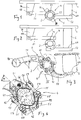
- a fastening section 4 On a fastening section 4, however ( Fig. 5 . Fig. 7 ))
- the axial cross section is no longer circular, but rather angular with the formation of flat support surfaces, which is described in more detail below.
- the round tube 2 can also receive non-circular cross sections at its two ends as a result of deformation processes carried out there, for. B. in order to better fix a steering knuckle or a brake carrier.
- the deformation of the round tube 2 limited to the fastening section 4 is such that two flat supporting surfaces 11, 33 are created by partially pressing in two circumferential sections of the round tube facing away from one another.
- the flat support surface 11 bears against a corresponding counter support surface 61 on the front link section 51, and the flat support surface 33 bears against the counter support surface 63 on the rear link section 52.
- the front handlebar section 51 is provided with a shell 41
- the rear handlebar section 52 is also provided with a shell 42.
- the shells 41, 42 are an integral part of the cast handlebar sections 51, 52.
- the cast design is such that the handlebar section 51 abuts the shell 41 obliquely downwards and the handlebar section 52 abuts the shell 42 obliquely upward ,
- the shells 41, 42, facing the axle body 2 each have a first inside 46 and a second inside 47 forming a corner angle of approximately 90 ° together with the first inside.
- the handlebar sections 51, 52 are not supported against the axle body 2 on the entire surface of the two inner sides 46, 47, but only in one of them Edge zone facing away from the corner angle of the respective inner side. In this edge zone there is in each case a projection extending in the longitudinal direction of the axle body 2, similar to a bar.
- the projection forms a support surface 61, 62, 63, 64, and only on this support surface 61, 62, 63, 64 does contact between the axle body 2 and the axle guide 5 take place.
- the link sections 51, 52 are supported against support surfaces 11, 22, 33, 44 on the axle body 2.
- the support surfaces 11, 22, 33, 44 are formed by partially pressing in the originally circular axle body 2 in a forming process. For this purpose, parts of the round tube wall are pressed inwards in a compression tool.
- the required clamping force is achieved by tension elements 57, which clamp the one shell 41 against the other shell 42 with the fastening section 4 of the axle body 2 interposed. This bracing takes place at an oblique angle W to the horizontal.
- each shell 41, 42 When viewed in the axial direction, each shell 41, 42 has a length that is greater than the other width of the handlebar sections 51, 52. In this way, the shells 41, 42 are long supported on the fastening section 4 When tightening the tension elements 57 while increasing the clamping tension, the counter support surfaces 61, 62, 63, 64 of the shells, which are shaped like a strip, are clamped on the support surfaces 11, 22, 33, 44 of the axle beam.
- the angular shell 41 of the front link section 51 is supported against the axle body 2 from above and from the front at the same time.
- the angular shell 42 of the rear link section 52 is supported from below and from behind against the axle beam.
- the inner sides 46, 47 of both shells together enclose the axle body 2 almost over the entire circumference. So there is only a small, not enclosed circumferential distance between the shells. This circumferential distance is necessary so that there is no contact between the shells 41, 42 under any circumstances and also when the axle suspension is subjected to high torsional loads.
- the clamping force required for clamping the fastening section 4 is achieved by demountable tension elements which brace the shell of the front link section 51 with the interposition of the axle body 2 against the shell of the rear link section 52.
- This bracing takes place at an oblique angle W to the horizontal.
- she takes place by means of two threaded brackets 55, each consisting of a curved bracket section 56 and two straight, mutually parallel sections 57, which transmit the tensile force as the actual tensile elements.
- the sections 57 are provided with external threads, onto each of which a threaded nut 58 is screwed.
- each threaded bracket 55 is guided around an abutment 59 formed on the front link section 51.
- the abutment 59 is a lug integrally formed on the handlebar section 51, which is provided with a groove corresponding to the bend of the bracket section 56.
- the tension elements 57 extend longitudinally, ie. H. extend parallel to the course of the axle guide 5, and the ends of the tension elements 57 with the nuts 58 screwed there extend backwards and obliquely downwards. In this way, an optimally protected position of the tension elements is achieved, since even in the event of an extreme deflection of the axle control arm 5, there is no contact with the chassis parts of the vehicle arranged above.
- the Fig. 6 shows a section through the fastening section 4 of the axle tube corresponding to that in FIG Fig. 5 reproduced section plane VI-VI. It can be seen that the axle body in the fastening section 4 does not have a round jacket surface 70 as on the other axle tube sections, but rather an axle tube cross section made of partially flat and partially curved surfaces.
- four support surfaces 11, 22, 33, 44 have been formed, each of which is flat and flat.
- the support surfaces 11, 22, 33, 44 are axle tube regions which are created by pressing in the originally round axle tube jacket.
- the support surfaces 11, 22 are close together and are separated from one another only by a corner radius 71. They are arranged at right angles to each other. The same applies to the two support surfaces 33 and 44. Between the support surfaces 11 and 44 on the one hand and 22 and 33 on the other hand, arcuate tube wall sections 73 extend.
- first support region 11 is located on a first circumferential segment S1, the second support region 22 on a second circumferential segment S2, the third support region 33 on a third circumferential segment S3 and the fourth support region 44 on a fourth circumferential segment S4 of the round tube.
- the first The circumferential segment S1 is arranged on a circumferential section of the tube facing away from the third circumferential segment S3, and the second circumferential segment S2 is arranged on a circumferential section facing away from the fourth circumferential segment S4.
- the tube wall 72 is not or only slightly deformed in comparison to the original lateral surface 70.
- the Figures 7 and 8 show compared to the Figures 5 and 6 a greater deformation of the axle tube in the fastening section 4.
- the deformation is so strong that the outer diameter on the fastening section 4 is smaller over its entire circumference than the outer surface 70 and thus the outer diameter on the undeformed pipe sections.
- Fig. 8 denoted those areas of the tube wall 72 at which deformation forces F act on the round tube wall.
- Fig. 9 four circumferential sections of the round tube wall are pressed inwards in a swaging tool equipped with four press jaws which can be moved towards one another and are thereby permanently deformed.
- the round tube 2 is first inserted into a pressing tool 80 in such a way that that longitudinal section of the round tube which will later be the fastening section 4 is arranged in the region of the pressure surfaces of the pressing tool 80.
- Components of the pressing tool 80 are an upper and a lower tool 81, 82, the pressure surfaces 85, 86 of which are directed towards one another, and two side pressure cheeks 83, 84, the pressure surfaces of which are also directed towards one another.
- the tube section is formed by simultaneously moving the two pressure surfaces 85, 86 and the two pressure surfaces of the side pressing cheeks 83, 84 against one another until the desired tube cross section is reached.
- the simultaneous movement of the pressing jaws can be achieved by the upper and lower tools 81, 82 driving the side pressing cheeks 83, 84 over inclined sliding surfaces 88. Additional pressure surfaces can be formed at the ends of the four tools, which pressure areas cover the two transition regions 90 ( Fig. 5 ) from the fastening section 4 to the round pipe sections.
Landscapes
- Engineering & Computer Science (AREA)
- Mechanical Engineering (AREA)
- Vehicle Body Suspensions (AREA)
Description
Die Erfindung betrifft ein Fahrwerk für ein Nutzfahrzeug mit einem Achskörper, der in einem Befestigungsabschnitt mit einem Achslenker verbunden ist, dessen eines Ende an dem Fahrzeugrahmen des Nutzfahrzeugs schwenkbar gelagert, und dessen anderes Ende über eine Luftfeder gegen den Fahrzeugrahmen abgestützt ist, wobei der Achskörper in seinem Befestigungsabschnitt mit zumindest zwei Stützflächen versehen und mit diesen Stützflächen gegen den Achslenker abgestützt ist, und der Achskörper im Wesentlichen als ein Rundrohr ausgebildet ist, wobei jede Stützfläche eine Verformung der Rundrohrwandung ist, und in Umfangsrichtung des Rundrohrs
- eine erste Stützfläche auf einem ersten Umfangssegment des Rundrohrs,
- eine zweite Stützfläche auf einem zweiten Umfangssegment des Rundrohrs,
- eine dritte Stützfläche auf einem dritten Umfangssegment des Rundrohrs,
- eine vierte Stützfläche auf einem vierten Umfangssegment des Rundrohrs
- a first support surface on a first circumferential segment of the round tube,
- a second support surface on a second circumferential segment of the round tube,
- a third support surface on a third circumferential segment of the round tube,
- a fourth support surface on a fourth peripheral segment of the round tube
Die Erfindung betrifft ferner einen Achskörper, welcher Verwendung in einem solchen Fahrwerk finden kann.The invention further relates to an axle body, which can be used in such a chassis.
Bei einem Fahrwerk und einem Achskörper nach der
Aus der
Aus der
Aus der
Der Erfindung liegt die Aufgabe zugrunde, durch Einsatz kostengünstiger Achsrohre zu insgesamt günstigen Herstellkosten für den Achskörper und das den Achskörper beinhaltende Fahrwerk zu gelangen.The invention has for its object to achieve inexpensive manufacturing costs for the axle body and the chassis containing the axle body by using inexpensive axle tubes.
Zur Lösung dieser Aufgabe wird ein Fahrwerk für ein Nutzfahrzeug mit den Merkmalen des Anspruchs 1 sowie ein Achskörper mit den Merkmalen des Anspruchs 7 vorgeschlagen.To achieve this object, a chassis for a commercial vehicle with the features of
Von Vorteil ist hierbei die Verwendung eines preiswert herstellbaren Achskörpers aus Rundrohr. Um gleichwohl hohe Momente und insbesondere Bremsmomente vom Achskörper auf den jeweiligen Achslenker übertragen zu können, ist das Rundrohr an der Achseinbindung, also auf dem Befestigungsabschnitt mit dem Achslenker unter Ausbildung von Stützbereichen verformt. Diese Stützbereiche sind daher verformte Bereiche der ursprünglich kreisrunden Rohrwandung.The advantage here is the use of an inexpensive to produce shaft body made of round tube. In order to nevertheless be able to transmit high torques and in particular braking torques from the axle body to the respective axle link, the round tube is deformed at the axle connection, that is to say on the fastening section with the axle link, with the formation of support areas. These support areas are therefore deformed areas of the originally circular tube wall.
Der Achskörper ist daher auf dem größten Teil seiner Länge ein Rundrohr von kreisförmigem Achsquerschnitt. Auf dem Befestigungsabschnitt jedoch ist infolge zuvor an dem Rundrohr durchgeführter Verformungsprozesse der Achsquerschnitt nicht mehr kreisförmig, sondern kantig unter Ausbildung jener Stützflächen, an denen der Achskörper im Achslenker eingeklemmt ist.For most of its length, the axle body is a round tube with a circular axis cross section. On the fastening section, however, as a result of deformation processes previously carried out on the round tube, the axle cross section is no longer circular, but rather angular, with the formation of those support surfaces on which the axle body is clamped in the axle link.
Bevorzugte Ausgestaltungen des erfindungsgemäßen Fahrwerks sowie des erfindungsgemäßen Achskörpers sind in den jeweiligen Unteransprüchen angegeben.Preferred configurations of the chassis according to the invention and of the axle body according to the invention are specified in the respective subclaims.
Weitere Vorteile und Einzelheiten ergeben sich aus der nachfolgenden Beschreibung von Ausführungsbeispielen, welche auf der Zeichnung dargestellt sind. Darin zeigen im Einzelnen
- Fig. 1
- in einer Seitenansicht ein Nutzfahrzeug-Fahrwerk in einer ersten Ausführungsform;
- Fig. 2
- in einer Seitenansicht ein Nutzfahrzeug-Fahrwerk in einer zweiten Ausführungsform;
- Fig. 3
- in einer Seitenansicht ein Nutzfahrzeug-Fahrwerk in einer dritten Ausführungsform;
- Fig. 4
- eine vergrößerte Darstellung des in
Fig. 3 mit IV bezeichneten Befestigungsbereichs des Achskörpers im Achslenker; - Fig. 5
- eine Teilansicht des Achskörpers, wobei vor allem der Befestigungsabschnitt wiedergegeben ist;
- Fig. 6
- den Achsrohrquerschnitt im Befestigungsabschnitt des Achskörpers entsprechend der in
Fig. 5 eingezeichneten Schnittebene VI-VI; - Fig. 7
- eine Teilansicht des Achskörpers, wobei vor allem der Befestigungsabschnitt wiedergegeben ist;
- Fig. 8
- den Achsrohrquerschnitt im Befestigungsabschnitt des Achskörpers entsprechend der in
Fig. 7 eingezeichneten Schnittebene VIII-VIII und - Fig. 9
- eine Stirnansicht einer Pressvorrichtung für ein Umformverfahren.
- Fig. 1
- a side view of a commercial vehicle chassis in a first embodiment;
- Fig. 2
- a side view of a commercial vehicle chassis in a second embodiment;
- Fig. 3
- a side view of a commercial vehicle chassis in a third embodiment;
- Fig. 4
- an enlarged view of the in
Fig. 3 with IV designated attachment area of the axle beam in the wishbone; - Fig. 5
- a partial view of the axle body, in particular the fastening section is shown;
- Fig. 6
- the axle tube cross-section in the fastening section of the axle body according to the in
Fig. 5 drawn section plane VI-VI; - Fig. 7
- a partial view of the axle body, in particular the fastening section is shown;
- Fig. 8
- the axle tube cross-section in the fastening section of the axle body according to the in
Fig. 7 marked cutting plane VIII-VIII and - Fig. 9
- an end view of a pressing device for a forming process.
Die auf der Zeichnung dargestellte Achsaufhängung findet Anwendung vor allem für Fahrzeugachsen mit durchgehendem Achskörper. Derartige Fahrzeugachsen kommen vor allem bei Nutzfahrzeugen und insbesondere bei Lkw-Anhängern und - Aufliegern zum Einsatz, da die Achsen für hohe Transportgewichte und Belastungen im Straßenbetrieb ausgelegt sind.The axle suspension shown in the drawing is used primarily for vehicle axles with a continuous axle body. Vehicle axles of this type are used above all in commercial vehicles and in particular in truck trailers and semi-trailers, since the axles are designed for high transport weights and loads in road operation.
Unter Längsträgern eines hier nicht näher dargestellten Fahrwerks 1 ist auf jeder Fahrzeugseite eine Lenkerstütze 1A befestigt. Diese nimmt ein Schwenklager 1B für die Achsaufhängung auf. Zur Führung des von einer Fahrzeugseite zur anderen Fahrzeugseite starr durchgehenden Achskörpers 2 dient auf jeder Fahrzeugseite ein Achslenker 5. Der Achslenker 5 ist an seinem vorderen Ende mit einem einstückig angegossenen Lenkerauge versehen, welches Bestandteil des Schwenklagers 1B ist, um so mittels eines Bolzens den Achslenker 5 vertikal schwenkbar an der Lenkerstütze 1A zu halten.A
In Fahrtrichtung hinten ist an dem Achslenker 5 eine Auflagefläche 6A für eine Luftfeder 6 ausgebildet. Die Luftfeder 6 stützt sich mit einer oberen Abschlussplatte von unten gegen den entsprechenden Längsträger des Fahrwerks 1 ab.In the rear direction of travel, a
Der Achslenker 5 ist zweiteilig gestaltet. Er setzt sich zusammen aus einem in Fahrtrichtung vorderen Lenkerabschnitt 51 sowie einem in Fahrtrichtung hinteren Lenkerabschnitt 52. An dem hinteren Lenkerabschnitt 52 ist die Auflagefläche 6A für die Luftfeder 6 angeformt.The
Der vordere Lenkerabschnitt 51 erstreckt sich von dem Lagerauge des Schwenklagers 1B bis zu dem Achskörper 2. Er läuft mit seinem hinteren Ende nach schräg unten aus. Der hintere Lenkerabschnitt 52 erstreckt sich von dem Achskörper 2 bis zu der Auflagefläche für die Luftfeder 6. Er läuft mit seinem vorderen Ende nach schräg oben aus. Die Zweiteiligkeit des Achslenkers 5 ist von Vorteil, da durch Auswahl von Lenkerabschnitten 51, 52 in geeigneter Größe die fahrzeugspezifischen Abstände zwischen dem Schwenklager, dem Achskörper 2 und der Luftfeder 6 individuell, d. h. kundenspezifisch, realisierbar sind.The
Der vordere Lenkerabschnitt 51 besteht aus Metallguss, vorzugsweise aus einem Sphärostahlguss. Vorzugsweise besteht auch der hintere Lenkerabschnitt 52 aus Metallguss, vorzugsweise einem Sphärostahlguss.The
Der Achskörper 2 ist auf dem größten Teil seiner Länge ein Rundrohr von kreisförmigem Achsquerschnitt. Auf einem Befestigungsabschnitt 4 jedoch (
Außerdem kann das Rundrohr 2 auch an seinen beiden Enden infolge dort durchgeführter Verformungsprozesse unrunde Querschnitte erhalten, z. B. um dort einen das Fahrzeugrad lagernden Achsschenkel oder einen Bremsträger besser befestigen zu können.In addition, the
Bei den Ausführungsformen nach
Gemeinsam ist allen Ausführungsformen, dass auf dem Befestigungsabschnitt 4, der nur einen kleinen Teil der Gesamtlänge des Achskörpers 2 ausmacht, ein im wesentlichen formschlüssiges Einklemmen des Achsrohrs zwischen den beiden Lenkerabschnitten 51, 52 erfolgt.Common to all of the embodiments is that on the
Bei den Ausführungsformen nach den
Die Schalen 41, 42 weisen, dem Achskörper 2 zugewandt, jeweils eine erste Innenseite 46 und eine gemeinsam mit der ersten Innenseite einen Eckwinkel von ca. 90° bildende zweite Innenseite 47 auf. Die Abstützung der Lenkerabschnitte 51, 52 gegen den Achskörper 2 erfolgt nicht auf der ganzen Fläche der beiden Innenseiten 46, 47, sondern nur in einer dem Eckwinkel abgewandten Randzone der jeweiligen Innenseite. In dieser Randzone befindet sich jeweils ein sich in Längsrichtung des Achskörpers 2 erstreckender Vorsprung ähnlich einer Leiste. Der Vorsprung bildet eine Stützfläche 61, 62, 63, 64, und ausschließlich an dieser Stützfläche 61, 62, 63, 64 findet ein Kontakt zwischen dem Achskörper 2 und dem Achslenker 5 statt.The
Mit den vorzugsweise flach ausgebildeten Stützflächen 61, 62, 63, 64 an den Innenseiten der Schalen 41, 42 stützen sich die Lenkerabschnitte 51, 52 gegen Stützflächen 11, 22, 33, 44 am Achskörper 2 ab. Die Stützflächen 11, 22, 33, 44 sind durch partielles Eindrücken des ursprünglich kreisrunden Achskörpers 2 in einem Umformprozess gebildet. Hierzu werden in einem Stauchwerkzeug Teile der Rundrohrwandung nach innen eingedrückt.With the preferably flat support surfaces 61, 62, 63, 64 on the inner sides of the
Die erforderliche Klemmkraft wird durch Zugelemente 57 erreicht, welche die eine Schale 41 unter Zwischenlage des Befestigungsabschnitts 4 des Achskörpers 2 gegen die andere Schale 42 verspannen. Diese Verspannung erfolgt unter einem schrägen Winkel W zur Horizontalen.The required clamping force is achieved by
Jede Schale 41, 42 weist, in Achsrichtung gesehen, eine Länge auf, die größer ist, als die sonstige Breite der Lenkerabschnitte 51, 52. Auf diese Weise ergibt sich in Achsrichtung eine lange Abstützung der Schalen 41, 42 an dem Befestigungsabschnitt 4. Es kommt beim Anziehen der Zugelemente 57 unter Erhöhung der Klemmspannung zu einem Klemmen der ähnlich einer Leiste geformten Gegenstützflächen 61, 62, 63, 64 der Schalen an den Stützflächen 11, 22, 33, 44 des Achskörpers.When viewed in the axial direction, each
Bei montierter Achsaufhängung stützt sich die winkelförmige Schale 41 des vorderen Lenkerabschnitts 51 zugleich von oben und von vorne gegen den Achskörper 2 ab. Hingegen stützt sich die winkelförmige Schale 42 des hinteren Lenkerabschnitts 52 zugleich von unten und von hinten gegen den Achskörper ab. Die Innenseiten 46, 47 beider Schalen zusammen umschließen den Achskörper 2 nahezu über den gesamten Umfang. Es verbleibt also nur ein kleiner nicht umschlossener Umfangsabstand zwischen den Schalen. Dieser Umfangsabstand ist erforderlich, damit es unter keinen Umständen und auch nicht bei starker Torsionsbelastung der Achsaufhängung zu einer Berührung der Schalen 41, 42 kommt.When the axle suspension is installed, the
Die für das Klemmen des Befestigungsabschnitts 4 erforderliche Klemmkraft wird durch demontierbare Zugelemente erreicht, welche die Schale des vorderen Lenkerabschnitts 51 unter Zwischenlage des Achskörpers 2 gegen die Schale des hinteren Lenkerabschnitts 52 verspannen. Diese Verspannung erfolgt unter dem schrägen Winkel W zur Horizontalen. Sie erfolgt mittels zweier Gewindebügel 55, bestehend jeweils aus einem gebogenen Bügelabschnitt 56 und zwei geraden, zueinander parallelen Abschnitten 57, welche als die eigentlichen Zugelemente die Zugkraft übertragen. Im Bereich ihrer freien Enden sind die Abschnitte 57 mit Außengewinden versehen, auf die jeweils eine Gewindemutter 58 aufgeschraubt ist.The clamping force required for clamping the
Der Bügelabschnitt 56 jedes Gewindebügels 55 ist um ein an dem vorderen Lenkerabschnitt 51 angeformtes Widerlager 59 herumgeführt. Bei dem Widerlager 59 handelt es sich um eine einstückig an dem Lenkerabschnitt 51 angeformte Nase, die mit einer zu der Biegung des Bügelabschnitts 56 korrespondierenden Rille versehen ist.The
Aufgrund der Anordnung der Gewindebügel 55 wird erreicht, dass sich im Bereich der Achseinbindung die Zugelemente 57 längs, d. h. parallel, des Verlaufs des Achslenkers 5 erstrecken, und sich die Enden der Zugelemente 57 mit den dort aufgeschraubten Muttern 58 nach hinten und schräg unten erstrecken. So wird eine optimal geschützte Lage der Zugelemente erreicht, da es selbst im Fall einer extremen Einfederung des Achslenkers 5 zu keinem Kontakt mit den oberhalb angeordneten Chassisteilen des Fahrzeugs kommt.Due to the arrangement of the threaded
Die
Die Stützflächen 11, 22 liegen eng beieinander und sind nur durch einen Eckenradius 71 voneinander getrennt. Sie sind im rechten Winkel zueinander angeordnet. Gleiches gilt für die beiden Stützflächen 33 und 44. Zwischen den Stützflächen 11 und 44 einerseits und 22 und 33 andererseits erstrecken sich bogenförmige Rohrwandungsabschnitte 73.The support surfaces 11, 22 are close together and are separated from one another only by a
Des Weiteren lässt
Zwischen dem Umfangssegment S1 und dem Umfangssegment S4, und ebenso zwischen dem Umfangssegment S2 und dem Umfangssegment S3 ist die Rohrwandung 72 nicht oder nur wenig im Vergleich zu der ursprünglichen Mantelfläche 70 verformt.Between the circumferential segment S1 and the circumferential segment S4, and also between the circumferential segment S2 and the circumferential segment S3, the
Die
Zur Erläuterung des Verformungsprozesses sind in
Gemäß
- 11
- Fahrwerklanding gear
- 1A1A
- Lenkerstützehandlebar Post
- 1B1B
- Schwenklagerpivot bearing
- 22
- Rundrohr, AchskörperRound tube, axle beam
- 44
- Befestigungsabschnittattachment section
- 55
- Achslenkerwishbone
- 66
- Luftfederair spring
- 6A6A
- Auflagefläche für LuftfederSupport surface for air spring
- 1111
- Stützflächesupport surface
- 2222
- Stützflächesupport surface
- 3333
- Stützflächesupport surface
- 4141
- SchaleBowl
- 4242
- SchaleBowl
- 4444
- Stützflächesupport surface
- 4646
- Innenseiteinside
- 4747
- Innenseiteinside
- 5151
- vorderer Lenkerabschnittfront handlebar section
- 5252
- hinterer Lenkerabschnittrear handlebar section
- 5555
- Gewindebügelclevis
- 5656
- gebogener Bügelabschnittcurved temple section
- 5757
- Zugelementtension element
- 5858
- Muttermother
- 5959
- Widerlagerabutment
- 6161
- GegenstützflächeAgainst support surface
- 6262
- GegenstützflächeAgainst support surface
- 6363
- GegenstützflächeAgainst support surface
- 6464
- GegenstützflächeAgainst support surface
- 7070
- Mantelflächelateral surface
- 7171
- Eckenradiuscorner radius
- 7272
- Rohrwandungpipe wall
- 7373
- RohrwandungsabschnittRohrwandungsabschnitt
- 8080
- Presswerkzeugpress tool
- 8181
- Oberwerkzeugupper tool
- 8282
- Unterwerkzeuglower tool
- 8383
- SeitenpresswangeSide compression beam
- 8484
- SeitenpresswangeSide compression beam
- 8585
- Druckflächeprint area
- 8686
- Druckflächeprint area
- 8888
- Kulissenflächesliding-surface
- 9090
- ÜbergangsbereichTransition area
- FF
- Verformungskraftdeforming force
- S1S1
- Umfangssegmentperipheral segment
- S2S2
- Umfangssegmentperipheral segment
- S3S3
- Umfangssegmentperipheral segment
- S4S4
- Umfangssegmentperipheral segment
- WW
- Winkelangle
Claims (10)
- Chassis for a commercial vehicle having an axle beam (2) which is connected in a fastening section (4) to an axle guide (5), the one end of which is mounted pivotably on the vehicle frame (1) of the commercial vehicle, and the other end of which is supported via an air spring (6) against the vehicle frame (1), the axle beam (2) being provided with at least two supporting faces (11, 22, 33, 44) in its fastening section (4), and being supported by way of the said supporting faces against the axle guide (5), and the axle beam being configured substantially as a round tube (2), each supporting face (11, 22, 33, 44) being a deformation of the round tube wall (72), characterized in that, in the circumferential direction of the round tube (2),- a first supporting face (11) is arranged on a first circumferential segment (S1) of the round tube,- a second supporting face (22) is arranged on a second circumferential segment (S2) of the round tube,- a third supporting face (33) is arranged on a third circumferential segment (S3) of the round tube, and- a fourth supporting face (44) is arranged on a fourth circumferential segment (S4) of the round tube,and the first and third circumferential segment (11, 33) and the second and fourth circumferential segment (22, 44) being arranged on circumferential sections which face away from one another, the axle guide (5) being split in two and being composed of a front (in the driving direction) guide section (51) and a rear (in the driving direction) guide section (52), and in that the first supporting face (11) and the fourth supporting face (44) are supported exclusively against the one of the two guide sections, and the second supporting face (22) and the third supporting face (33) are supported exclusively against the other one of the two guide sections.
- Chassis according to Claim 1, characterized in that the first (11) and the second (22) supporting face and the third (33) and the fourth (44) supporting face follow one another in each case in the circumferential direction, and are arranged at a right angle (R) with respect to one another.
- Chassis according to either of Claims 1 and 2, characterized in that corresponding supporting faces (61, 62, 63, 64) which are formed as strips which extend in the axial direction are configured on the guide sections (51, 52) for contact of the supporting faces (11, 22, 33, 44).
- Chassis according to Claim 3, characterized in that the corresponding supporting faces (61, 64 and 62, 63, respectively) which are configured on each guide section (51, 52) are arranged at a right angle with respect to one another.
- Chassis according to one of the preceding claims, characterized in that the axle beam (2) has a different wall thickness on its fastening section (4) than on the non-deformed tube longitudinal sections.
- Chassis according to one of the preceding claims, characterized in that the external diameter of the axle beam (2) on the fastening section (4) over its entire circumference is smaller than the external diameter on the non-deformed tube longitudinal sections.
- Axle beam having a fastening section (4) for connecting the axle beam to an axle guide of a chassis and, in particular, commercial vehicle chassis, the axle beam being provided with at least two supporting regions (11, 22, 33, 44) in the fastening section (4), and being supportable by way of the said supporting regions against the axle guide, and the axle beam being configured substantially as a round tube (2), each supporting region (11, 22, 33, 44) being a deformation of the round tube wall, characterized in that in the circumferential direction of the round tube (2),- a first supporting face (11) is arranged on a first circumferential segment (S1) of the round tube,- a second supporting face (22) is arranged on a second circumferential segment (S2) of the round tube,- a third supporting face (33) is arranged on a third circumferential segment (S3) of the round tube, and- a fourth supporting face (44) is arranged on a fourth circumferential segment (S4) of the round tube,and the first and third circumferential segment (11, 33) and the second and fourth circumferential segment (22, 44) being arranged on circumferential sections which face away from one another.
- Axle beam according to Claim 7, characterized in that the first (11) and the second (22) supporting face and the third (33) and the fourth (44) supporting face follow one another in each case in the circumferential direction, and are arranged at a right angle (R) with respect to one another.
- Axle beam according to either of Claims 7 and 8, characterized in that the axle beam (2) has a different wall thickness on its fastening section (4) than on the non-deformed tube longitudinal sections.
- Axle beam according to one of Claims 7 to 9, characterized in that the external diameter of the axle beam (2) on the fastening section (4) over its entire circumference is smaller than the external diameter on the non-deformed tube longitudinal sections.
Priority Applications (1)
| Application Number | Priority Date | Filing Date | Title |
|---|---|---|---|
| PL14155689T PL2772372T3 (en) | 2013-02-28 | 2014-02-19 | Suspension for a commercial vehicle and axle body |
Applications Claiming Priority (1)
| Application Number | Priority Date | Filing Date | Title |
|---|---|---|---|
| DE102013003301.2A DE102013003301A1 (en) | 2013-02-28 | 2013-02-28 | Chassis for a commercial vehicle, axle body and method for producing an axle body |
Publications (2)
| Publication Number | Publication Date |
|---|---|
| EP2772372A1 EP2772372A1 (en) | 2014-09-03 |
| EP2772372B1 true EP2772372B1 (en) | 2020-01-15 |
Family
ID=50137507
Family Applications (1)
| Application Number | Title | Priority Date | Filing Date |
|---|---|---|---|
| EP14155689.4A Active EP2772372B1 (en) | 2013-02-28 | 2014-02-19 | Suspension for a commercial vehicle and axle body |
Country Status (3)
| Country | Link |
|---|---|
| EP (1) | EP2772372B1 (en) |
| DE (1) | DE102013003301A1 (en) |
| PL (1) | PL2772372T3 (en) |
Families Citing this family (4)
| Publication number | Priority date | Publication date | Assignee | Title |
|---|---|---|---|---|
| DE102015105966B4 (en) * | 2015-04-20 | 2021-01-28 | Saf-Holland Gmbh | Reinforcement unit |
| DE102017115692A1 (en) * | 2017-07-12 | 2019-01-17 | Bpw Bergische Achsen Kg | Achslenker and axle suspension for a vehicle axle |
| US11679624B2 (en) | 2017-09-23 | 2023-06-20 | Hendrickson Usa, L.L.C. | Fabricated axle seat assembly |
| DE102020103762B4 (en) | 2020-02-13 | 2023-10-12 | Saf-Holland Gmbh | Handlebar system |
Family Cites Families (7)
| Publication number | Priority date | Publication date | Assignee | Title |
|---|---|---|---|---|
| DE2805729C2 (en) * | 1978-02-08 | 1986-02-20 | Mannesmann AG, 4000 Düsseldorf | Process for the production of pre-workpieces for axle beam halves of commercial vehicles |
| DE29615286U1 (en) * | 1996-09-04 | 1996-10-17 | Trenkamp & Gehle GmbH, 49413 Dinklage | Wheel axle for commercial vehicles |
| DE102007010021B4 (en) * | 2007-03-01 | 2020-02-27 | Saf-Holland Gmbh | Axle beam, chassis arrangement and process for their manufacture |
| DE102008061190A1 (en) | 2008-12-09 | 2010-06-10 | Bpw Bergische Achsen Kg | Axle suspension for a vehicle axle |
| CN102317092A (en) * | 2009-02-17 | 2012-01-11 | 维维乐内德兰公司 | Support for pneumatic spring of wheel axle suspension |
| EP2499009B1 (en) * | 2009-11-10 | 2016-10-05 | VDL Weweler B.V. | Wheel axle suspension having clamp bodies with a protrusion for attaching an indented tubular axle to trailing arms |
| NZ607267A (en) * | 2010-09-30 | 2015-01-30 | Hendrickson Usa Llc | Heavy-duty vehicle axle-to-beam connection |
-
2013
- 2013-02-28 DE DE102013003301.2A patent/DE102013003301A1/en not_active Withdrawn
-
2014
- 2014-02-19 EP EP14155689.4A patent/EP2772372B1/en active Active
- 2014-02-19 PL PL14155689T patent/PL2772372T3/en unknown
Non-Patent Citations (1)
| Title |
|---|
| None * |
Also Published As
| Publication number | Publication date |
|---|---|
| DE102013003301A1 (en) | 2014-08-28 |
| EP2772372A1 (en) | 2014-09-03 |
| PL2772372T3 (en) | 2020-06-15 |
Similar Documents
| Publication | Publication Date | Title |
|---|---|---|
| EP2607115B1 (en) | Axle suspension for a vehicle axle | |
| EP2961623B1 (en) | Chassis for a commercial vehicle, axle body and method for producing an axle body | |
| EP2847012B1 (en) | Axle fixation for a sprung vehicle axle | |
| EP3027437B1 (en) | Suspension arm | |
| EP2772372B1 (en) | Suspension for a commercial vehicle and axle body | |
| DE102011086480B4 (en) | Axle unit for commercial vehicles | |
| DE202017100162U1 (en) | Handlebar in shell construction for a suspension of a vehicle | |
| DE2262835C3 (en) | Suspension for a sprung rigid wheel axle | |
| DE19624242A1 (en) | Vehicle front wheel suspension with rigid axle | |
| EP3649038B1 (en) | Adjusting device for a chassis of a motor vehicle and rear-axle steering system | |
| DE10018315A1 (en) | Axle suspension for an air-sprung vehicle axle | |
| DE102006059586A1 (en) | Truck | |
| DE102017215171A1 (en) | Method for producing a vehicle handlebar for a suspension and vehicle handlebars | |
| EP2986459B1 (en) | Longitudinal control arm | |
| DE102017201811A1 (en) | Rear suspension for a vehicle | |
| EP2780182B1 (en) | Rigid axle with air suspension | |
| DE4127652A1 (en) | AFTER THE DEEP ELEMENT WORKING PRINCE | |
| EP3573851B1 (en) | Fork for articulation and actuator with a fork for an articulation | |
| DE102017201747B3 (en) | Independent suspension of a vehicle | |
| DE102018006572B4 (en) | Vehicle suspension arrangement for at least one wheel axle | |
| EP2332751B1 (en) | Lorry pivot bar with separated bar | |
| DE102017005810B4 (en) | ARRANGEMENT FOR MOUNTING A FIFTH-PART PLATE TO A VEHICLE FRAME | |
| DE9306266U1 (en) | Handlebar strut for wheel axles of commercial vehicles | |
| DE102019104428A1 (en) | Chassis for a commercial vehicle as well as axle shell for a chassis | |
| DE102016112153A1 (en) | Achseinbindung for a spring-loaded vehicle axle and intermediate piece of Achseinbindung |
Legal Events
| Date | Code | Title | Description |
|---|---|---|---|
| PUAI | Public reference made under article 153(3) epc to a published international application that has entered the european phase |
Free format text: ORIGINAL CODE: 0009012 |
|
| 17P | Request for examination filed |
Effective date: 20140219 |
|
| AK | Designated contracting states |
Kind code of ref document: A1 Designated state(s): AL AT BE BG CH CY CZ DE DK EE ES FI FR GB GR HR HU IE IS IT LI LT LU LV MC MK MT NL NO PL PT RO RS SE SI SK SM TR |
|
| AX | Request for extension of the european patent |
Extension state: BA ME |
|
| R17P | Request for examination filed (corrected) |
Effective date: 20150210 |
|
| RBV | Designated contracting states (corrected) |
Designated state(s): AL AT BE BG CH CY CZ DE DK EE ES FI FR GB GR HR HU IE IS IT LI LT LU LV MC MK MT NL NO PL PT RO RS SE SI SK SM TR |
|
| STAA | Information on the status of an ep patent application or granted ep patent |
Free format text: STATUS: EXAMINATION IS IN PROGRESS |
|
| 17Q | First examination report despatched |
Effective date: 20170216 |
|
| GRAP | Despatch of communication of intention to grant a patent |
Free format text: ORIGINAL CODE: EPIDOSNIGR1 |
|
| STAA | Information on the status of an ep patent application or granted ep patent |
Free format text: STATUS: GRANT OF PATENT IS INTENDED |
|
| INTG | Intention to grant announced |
Effective date: 20191002 |
|
| GRAS | Grant fee paid |
Free format text: ORIGINAL CODE: EPIDOSNIGR3 |
|
| GRAA | (expected) grant |
Free format text: ORIGINAL CODE: 0009210 |
|
| STAA | Information on the status of an ep patent application or granted ep patent |
Free format text: STATUS: THE PATENT HAS BEEN GRANTED |
|
| AK | Designated contracting states |
Kind code of ref document: B1 Designated state(s): AL AT BE BG CH CY CZ DE DK EE ES FI FR GB GR HR HU IE IS IT LI LT LU LV MC MK MT NL NO PL PT RO RS SE SI SK SM TR |
|
| REG | Reference to a national code |
Ref country code: CH Ref legal event code: EP Ref country code: GB Ref legal event code: FG4D Free format text: NOT ENGLISH |
|
| REG | Reference to a national code |
Ref country code: IE Ref legal event code: FG4D Free format text: LANGUAGE OF EP DOCUMENT: GERMAN |
|
| REG | Reference to a national code |
Ref country code: DE Ref legal event code: R096 Ref document number: 502014013455 Country of ref document: DE |
|
| REG | Reference to a national code |
Ref country code: AT Ref legal event code: REF Ref document number: 1224849 Country of ref document: AT Kind code of ref document: T Effective date: 20200215 |
|
| REG | Reference to a national code |
Ref country code: NL Ref legal event code: MP Effective date: 20200115 |
|
| REG | Reference to a national code |
Ref country code: LT Ref legal event code: MG4D |
|
| PG25 | Lapsed in a contracting state [announced via postgrant information from national office to epo] |
Ref country code: NL Free format text: LAPSE BECAUSE OF FAILURE TO SUBMIT A TRANSLATION OF THE DESCRIPTION OR TO PAY THE FEE WITHIN THE PRESCRIBED TIME-LIMIT Effective date: 20200115 Ref country code: RS Free format text: LAPSE BECAUSE OF FAILURE TO SUBMIT A TRANSLATION OF THE DESCRIPTION OR TO PAY THE FEE WITHIN THE PRESCRIBED TIME-LIMIT Effective date: 20200115 Ref country code: PT Free format text: LAPSE BECAUSE OF FAILURE TO SUBMIT A TRANSLATION OF THE DESCRIPTION OR TO PAY THE FEE WITHIN THE PRESCRIBED TIME-LIMIT Effective date: 20200607 Ref country code: FI Free format text: LAPSE BECAUSE OF FAILURE TO SUBMIT A TRANSLATION OF THE DESCRIPTION OR TO PAY THE FEE WITHIN THE PRESCRIBED TIME-LIMIT Effective date: 20200115 Ref country code: NO Free format text: LAPSE BECAUSE OF FAILURE TO SUBMIT A TRANSLATION OF THE DESCRIPTION OR TO PAY THE FEE WITHIN THE PRESCRIBED TIME-LIMIT Effective date: 20200415 |
|
| PG25 | Lapsed in a contracting state [announced via postgrant information from national office to epo] |
Ref country code: GR Free format text: LAPSE BECAUSE OF FAILURE TO SUBMIT A TRANSLATION OF THE DESCRIPTION OR TO PAY THE FEE WITHIN THE PRESCRIBED TIME-LIMIT Effective date: 20200416 Ref country code: BG Free format text: LAPSE BECAUSE OF FAILURE TO SUBMIT A TRANSLATION OF THE DESCRIPTION OR TO PAY THE FEE WITHIN THE PRESCRIBED TIME-LIMIT Effective date: 20200415 Ref country code: IS Free format text: LAPSE BECAUSE OF FAILURE TO SUBMIT A TRANSLATION OF THE DESCRIPTION OR TO PAY THE FEE WITHIN THE PRESCRIBED TIME-LIMIT Effective date: 20200515 Ref country code: HR Free format text: LAPSE BECAUSE OF FAILURE TO SUBMIT A TRANSLATION OF THE DESCRIPTION OR TO PAY THE FEE WITHIN THE PRESCRIBED TIME-LIMIT Effective date: 20200115 Ref country code: LV Free format text: LAPSE BECAUSE OF FAILURE TO SUBMIT A TRANSLATION OF THE DESCRIPTION OR TO PAY THE FEE WITHIN THE PRESCRIBED TIME-LIMIT Effective date: 20200115 Ref country code: SE Free format text: LAPSE BECAUSE OF FAILURE TO SUBMIT A TRANSLATION OF THE DESCRIPTION OR TO PAY THE FEE WITHIN THE PRESCRIBED TIME-LIMIT Effective date: 20200115 |
|
| REG | Reference to a national code |
Ref country code: CH Ref legal event code: PL |
|
| REG | Reference to a national code |
Ref country code: DE Ref legal event code: R097 Ref document number: 502014013455 Country of ref document: DE |
|
| REG | Reference to a national code |
Ref country code: BE Ref legal event code: MM Effective date: 20200229 |
|
| PG25 | Lapsed in a contracting state [announced via postgrant information from national office to epo] |
Ref country code: SM Free format text: LAPSE BECAUSE OF FAILURE TO SUBMIT A TRANSLATION OF THE DESCRIPTION OR TO PAY THE FEE WITHIN THE PRESCRIBED TIME-LIMIT Effective date: 20200115 Ref country code: EE Free format text: LAPSE BECAUSE OF FAILURE TO SUBMIT A TRANSLATION OF THE DESCRIPTION OR TO PAY THE FEE WITHIN THE PRESCRIBED TIME-LIMIT Effective date: 20200115 Ref country code: SK Free format text: LAPSE BECAUSE OF FAILURE TO SUBMIT A TRANSLATION OF THE DESCRIPTION OR TO PAY THE FEE WITHIN THE PRESCRIBED TIME-LIMIT Effective date: 20200115 Ref country code: DK Free format text: LAPSE BECAUSE OF FAILURE TO SUBMIT A TRANSLATION OF THE DESCRIPTION OR TO PAY THE FEE WITHIN THE PRESCRIBED TIME-LIMIT Effective date: 20200115 Ref country code: LU Free format text: LAPSE BECAUSE OF NON-PAYMENT OF DUE FEES Effective date: 20200219 Ref country code: MC Free format text: LAPSE BECAUSE OF FAILURE TO SUBMIT A TRANSLATION OF THE DESCRIPTION OR TO PAY THE FEE WITHIN THE PRESCRIBED TIME-LIMIT Effective date: 20200115 Ref country code: RO Free format text: LAPSE BECAUSE OF FAILURE TO SUBMIT A TRANSLATION OF THE DESCRIPTION OR TO PAY THE FEE WITHIN THE PRESCRIBED TIME-LIMIT Effective date: 20200115 Ref country code: CZ Free format text: LAPSE BECAUSE OF FAILURE TO SUBMIT A TRANSLATION OF THE DESCRIPTION OR TO PAY THE FEE WITHIN THE PRESCRIBED TIME-LIMIT Effective date: 20200115 Ref country code: ES Free format text: LAPSE BECAUSE OF FAILURE TO SUBMIT A TRANSLATION OF THE DESCRIPTION OR TO PAY THE FEE WITHIN THE PRESCRIBED TIME-LIMIT Effective date: 20200115 Ref country code: LT Free format text: LAPSE BECAUSE OF FAILURE TO SUBMIT A TRANSLATION OF THE DESCRIPTION OR TO PAY THE FEE WITHIN THE PRESCRIBED TIME-LIMIT Effective date: 20200115 |
|
| PLBE | No opposition filed within time limit |
Free format text: ORIGINAL CODE: 0009261 |
|
| STAA | Information on the status of an ep patent application or granted ep patent |
Free format text: STATUS: NO OPPOSITION FILED WITHIN TIME LIMIT |
|
| PG25 | Lapsed in a contracting state [announced via postgrant information from national office to epo] |
Ref country code: CH Free format text: LAPSE BECAUSE OF NON-PAYMENT OF DUE FEES Effective date: 20200229 Ref country code: LI Free format text: LAPSE BECAUSE OF NON-PAYMENT OF DUE FEES Effective date: 20200229 |
|
| 26N | No opposition filed |
Effective date: 20201016 |
|
| PG25 | Lapsed in a contracting state [announced via postgrant information from national office to epo] |
Ref country code: IE Free format text: LAPSE BECAUSE OF NON-PAYMENT OF DUE FEES Effective date: 20200219 |
|
| PG25 | Lapsed in a contracting state [announced via postgrant information from national office to epo] |
Ref country code: SI Free format text: LAPSE BECAUSE OF FAILURE TO SUBMIT A TRANSLATION OF THE DESCRIPTION OR TO PAY THE FEE WITHIN THE PRESCRIBED TIME-LIMIT Effective date: 20200115 Ref country code: BE Free format text: LAPSE BECAUSE OF NON-PAYMENT OF DUE FEES Effective date: 20200229 |
|
| GBPC | Gb: european patent ceased through non-payment of renewal fee |
Effective date: 20200415 |
|
| REG | Reference to a national code |
Ref country code: AT Ref legal event code: MM01 Ref document number: 1224849 Country of ref document: AT Kind code of ref document: T Effective date: 20200219 |
|
| PG25 | Lapsed in a contracting state [announced via postgrant information from national office to epo] |
Ref country code: GB Free format text: LAPSE BECAUSE OF NON-PAYMENT OF DUE FEES Effective date: 20200415 |
|
| PG25 | Lapsed in a contracting state [announced via postgrant information from national office to epo] |
Ref country code: AT Free format text: LAPSE BECAUSE OF NON-PAYMENT OF DUE FEES Effective date: 20200219 |
|
| REG | Reference to a national code |
Ref country code: DE Ref legal event code: R082 Ref document number: 502014013455 Country of ref document: DE Representative=s name: DREISS PATENTANWAELTE PARTG MBB, DE Ref country code: DE Ref legal event code: R082 Ref document number: 502014013455 Country of ref document: DE Representative=s name: JANKE SCHOLL PATENTANWAELTE PARTG MBB, DE |
|
| PG25 | Lapsed in a contracting state [announced via postgrant information from national office to epo] |
Ref country code: MT Free format text: LAPSE BECAUSE OF FAILURE TO SUBMIT A TRANSLATION OF THE DESCRIPTION OR TO PAY THE FEE WITHIN THE PRESCRIBED TIME-LIMIT Effective date: 20200115 Ref country code: CY Free format text: LAPSE BECAUSE OF FAILURE TO SUBMIT A TRANSLATION OF THE DESCRIPTION OR TO PAY THE FEE WITHIN THE PRESCRIBED TIME-LIMIT Effective date: 20200115 |
|
| PG25 | Lapsed in a contracting state [announced via postgrant information from national office to epo] |
Ref country code: MK Free format text: LAPSE BECAUSE OF FAILURE TO SUBMIT A TRANSLATION OF THE DESCRIPTION OR TO PAY THE FEE WITHIN THE PRESCRIBED TIME-LIMIT Effective date: 20200115 Ref country code: AL Free format text: LAPSE BECAUSE OF FAILURE TO SUBMIT A TRANSLATION OF THE DESCRIPTION OR TO PAY THE FEE WITHIN THE PRESCRIBED TIME-LIMIT Effective date: 20200115 |
|
| REG | Reference to a national code |
Ref country code: DE Ref legal event code: R082 Ref document number: 502014013455 Country of ref document: DE Representative=s name: DREISS PATENTANWAELTE PARTG MBB, DE |
|
| P01 | Opt-out of the competence of the unified patent court (upc) registered |
Effective date: 20230508 |
|
| PGFP | Annual fee paid to national office [announced via postgrant information from national office to epo] |
Ref country code: TR Payment date: 20240208 Year of fee payment: 11 Ref country code: PL Payment date: 20240122 Year of fee payment: 11 Ref country code: IT Payment date: 20240229 Year of fee payment: 11 Ref country code: FR Payment date: 20240222 Year of fee payment: 11 |
|
| PGFP | Annual fee paid to national office [announced via postgrant information from national office to epo] |
Ref country code: DE Payment date: 20240415 Year of fee payment: 11 |