EP2986352B1 - Verfahren für flüssigkeitschromatografiedatenanalyse - Google Patents
Verfahren für flüssigkeitschromatografiedatenanalyse Download PDFInfo
- Publication number
- EP2986352B1 EP2986352B1 EP15737791.2A EP15737791A EP2986352B1 EP 2986352 B1 EP2986352 B1 EP 2986352B1 EP 15737791 A EP15737791 A EP 15737791A EP 2986352 B1 EP2986352 B1 EP 2986352B1
- Authority
- EP
- European Patent Office
- Prior art keywords
- values
- liquid chromatography
- mixture
- volume
- wavelength
- Prior art date
- Legal status (The legal status is an assumption and is not a legal conclusion. Google has not performed a legal analysis and makes no representation as to the accuracy of the status listed.)
- Not-in-force
Links
- 238000004811 liquid chromatography Methods 0.000 title claims description 101
- 238000000034 method Methods 0.000 title claims description 99
- 238000007405 data analysis Methods 0.000 title description 3
- 239000000203 mixture Substances 0.000 claims description 76
- 230000008569 process Effects 0.000 claims description 64
- 238000002835 absorbance Methods 0.000 claims description 39
- 238000012545 processing Methods 0.000 claims description 25
- 102000004169 proteins and genes Human genes 0.000 claims description 18
- 108090000623 proteins and genes Proteins 0.000 claims description 18
- 239000007788 liquid Substances 0.000 claims description 16
- 239000012535 impurity Substances 0.000 claims description 15
- 238000000926 separation method Methods 0.000 claims description 9
- 239000000356 contaminant Substances 0.000 claims description 8
- 230000002349 favourable effect Effects 0.000 claims description 5
- 230000000052 comparative effect Effects 0.000 claims 1
- 238000010521 absorption reaction Methods 0.000 description 8
- 238000004587 chromatography analysis Methods 0.000 description 6
- 230000003993 interaction Effects 0.000 description 5
- 239000002594 sorbent Substances 0.000 description 5
- 239000002904 solvent Substances 0.000 description 4
- WEVYAHXRMPXWCK-UHFFFAOYSA-N Acetonitrile Chemical compound CC#N WEVYAHXRMPXWCK-UHFFFAOYSA-N 0.000 description 3
- OKKJLVBELUTLKV-UHFFFAOYSA-N Methanol Chemical compound OC OKKJLVBELUTLKV-UHFFFAOYSA-N 0.000 description 3
- 239000012491 analyte Substances 0.000 description 3
- 238000010586 diagram Methods 0.000 description 3
- 230000003287 optical effect Effects 0.000 description 3
- 239000002245 particle Substances 0.000 description 3
- 230000005526 G1 to G0 transition Effects 0.000 description 2
- VYPSYNLAJGMNEJ-UHFFFAOYSA-N Silicium dioxide Chemical compound O=[Si]=O VYPSYNLAJGMNEJ-UHFFFAOYSA-N 0.000 description 2
- 239000003463 adsorbent Substances 0.000 description 2
- 238000004458 analytical method Methods 0.000 description 2
- 238000004364 calculation method Methods 0.000 description 2
- 238000004891 communication Methods 0.000 description 2
- 230000006870 function Effects 0.000 description 2
- 230000014759 maintenance of location Effects 0.000 description 2
- 238000004519 manufacturing process Methods 0.000 description 2
- 239000000463 material Substances 0.000 description 2
- 102000039446 nucleic acids Human genes 0.000 description 2
- 108020004707 nucleic acids Proteins 0.000 description 2
- 150000007523 nucleic acids Chemical class 0.000 description 2
- 230000002093 peripheral effect Effects 0.000 description 2
- 229920001184 polypeptide Polymers 0.000 description 2
- 238000002360 preparation method Methods 0.000 description 2
- 102000004196 processed proteins & peptides Human genes 0.000 description 2
- 108090000765 processed proteins & peptides Proteins 0.000 description 2
- 239000007787 solid Substances 0.000 description 2
- 238000003491 array Methods 0.000 description 1
- 230000002542 deteriorative effect Effects 0.000 description 1
- 230000003292 diminished effect Effects 0.000 description 1
- 229910000078 germane Inorganic materials 0.000 description 1
- 239000008187 granular material Substances 0.000 description 1
- 230000002209 hydrophobic effect Effects 0.000 description 1
- 238000002347 injection Methods 0.000 description 1
- 239000007924 injection Substances 0.000 description 1
- 230000010354 integration Effects 0.000 description 1
- 239000003446 ligand Substances 0.000 description 1
- 238000004949 mass spectrometry Methods 0.000 description 1
- 230000007246 mechanism Effects 0.000 description 1
- 238000010606 normalization Methods 0.000 description 1
- 238000011056 performance test Methods 0.000 description 1
- 230000010399 physical interaction Effects 0.000 description 1
- 229920001690 polydopamine Polymers 0.000 description 1
- 229920000642 polymer Polymers 0.000 description 1
- 238000000746 purification Methods 0.000 description 1
- 238000004445 quantitative analysis Methods 0.000 description 1
- 230000004044 response Effects 0.000 description 1
- 230000000979 retarding effect Effects 0.000 description 1
- 239000000377 silicon dioxide Substances 0.000 description 1
- 238000003860 storage Methods 0.000 description 1
- 239000000126 substance Substances 0.000 description 1
- 239000000758 substrate Substances 0.000 description 1
- 239000002699 waste material Substances 0.000 description 1
- XLYOFNOQVPJJNP-UHFFFAOYSA-N water Substances O XLYOFNOQVPJJNP-UHFFFAOYSA-N 0.000 description 1
Images


Classifications
-
- G—PHYSICS
- G01—MEASURING; TESTING
- G01N—INVESTIGATING OR ANALYSING MATERIALS BY DETERMINING THEIR CHEMICAL OR PHYSICAL PROPERTIES
- G01N30/00—Investigating or analysing materials by separation into components using adsorption, absorption or similar phenomena or using ion-exchange, e.g. chromatography or field flow fractionation
- G01N30/02—Column chromatography
- G01N30/86—Signal analysis
- G01N30/8624—Detection of slopes or peaks; baseline correction
- G01N30/8631—Peaks
-
- G—PHYSICS
- G01—MEASURING; TESTING
- G01N—INVESTIGATING OR ANALYSING MATERIALS BY DETERMINING THEIR CHEMICAL OR PHYSICAL PROPERTIES
- G01N30/00—Investigating or analysing materials by separation into components using adsorption, absorption or similar phenomena or using ion-exchange, e.g. chromatography or field flow fractionation
- G01N30/02—Column chromatography
- G01N30/86—Signal analysis
- G01N30/8675—Evaluation, i.e. decoding of the signal into analytical information
- G01N30/8682—Group type analysis, e.g. of components having structural properties in common
-
- G—PHYSICS
- G16—INFORMATION AND COMMUNICATION TECHNOLOGY [ICT] SPECIALLY ADAPTED FOR SPECIFIC APPLICATION FIELDS
- G16B—BIOINFORMATICS, i.e. INFORMATION AND COMMUNICATION TECHNOLOGY [ICT] SPECIALLY ADAPTED FOR GENETIC OR PROTEIN-RELATED DATA PROCESSING IN COMPUTATIONAL MOLECULAR BIOLOGY
- G16B20/00—ICT specially adapted for functional genomics or proteomics, e.g. genotype-phenotype associations
-
- G—PHYSICS
- G01—MEASURING; TESTING
- G01N—INVESTIGATING OR ANALYSING MATERIALS BY DETERMINING THEIR CHEMICAL OR PHYSICAL PROPERTIES
- G01N30/00—Investigating or analysing materials by separation into components using adsorption, absorption or similar phenomena or using ion-exchange, e.g. chromatography or field flow fractionation
- G01N30/02—Column chromatography
- G01N30/26—Conditioning of the fluid carrier; Flow patterns
- G01N30/38—Flow patterns
- G01N30/46—Flow patterns using more than one column
-
- G—PHYSICS
- G01—MEASURING; TESTING
- G01N—INVESTIGATING OR ANALYSING MATERIALS BY DETERMINING THEIR CHEMICAL OR PHYSICAL PROPERTIES
- G01N30/00—Investigating or analysing materials by separation into components using adsorption, absorption or similar phenomena or using ion-exchange, e.g. chromatography or field flow fractionation
- G01N30/02—Column chromatography
- G01N30/62—Detectors specially adapted therefor
- G01N30/74—Optical detectors
-
- G—PHYSICS
- G01—MEASURING; TESTING
- G01N—INVESTIGATING OR ANALYSING MATERIALS BY DETERMINING THEIR CHEMICAL OR PHYSICAL PROPERTIES
- G01N30/00—Investigating or analysing materials by separation into components using adsorption, absorption or similar phenomena or using ion-exchange, e.g. chromatography or field flow fractionation
- G01N30/02—Column chromatography
- G01N30/86—Signal analysis
- G01N30/8651—Recording, data aquisition, archiving and storage
-
- G—PHYSICS
- G01—MEASURING; TESTING
- G01N—INVESTIGATING OR ANALYSING MATERIALS BY DETERMINING THEIR CHEMICAL OR PHYSICAL PROPERTIES
- G01N30/00—Investigating or analysing materials by separation into components using adsorption, absorption or similar phenomena or using ion-exchange, e.g. chromatography or field flow fractionation
- G01N30/02—Column chromatography
- G01N30/86—Signal analysis
- G01N30/8658—Optimising operation parameters
Definitions
- Liquid chromatography is a chromatographic technique used to separate components of a mixture based on a particular characteristic of the components. Liquid chromatography is used to identify each component in a mixture and to quantify each component.
- liquid chromatography involves a liquid sample being passed over a solid adsorbent material packed into a column using a flow of liquid solvent.
- Each component e.g., analyte
- Each component e.g., analyte
- the analytes flow off the column in a short amount of time, and if the interaction is strong, then the analytes take a longer time to flow off the column.
- the active component of the column is typically a granular material made of solid particles (e.g., silica, polymers, etc .), and can range from approximately 2-50 micrometers in size.
- the components of the sample mixture are separated from each other due to their different degrees of interaction with the sorbent particles.
- the pressurized liquid is typically a mixture of solvents (e.g. water, acetonitrile or methanol) and is referred to as a "mobile phase".
- the composition and temperature of the mobile phase liquid plays a major role in the separation process by influencing the interactions between sample components and the sorbent. These interactions are physical in nature, such as hydrophobic (dispersive), dipole-dipole and ionic, or some combination thereof.
- the sample mixture to be separated and analyzed is introduced, in a discrete small volume (typically microliters), into the stream of mobile phase percolating through the column.
- the components of the sample move through the column at different velocities, which are function of specific physical interactions with the sorbent (also called stationary phase).
- the velocity of each component depends on its chemical nature, on the nature of the stationary phase (column) and on the composition of the mobile phase.
- the time at which a specific analyte emerges from the column is referred to as its "retention time".
- the retention time measured under particular conditions is considered an identifying characteristic of a given analyte.
- a liquid chromatography system generally includes a sampler, pumps, and a detector.
- the sampler brings the sample mixture into the mobile phase stream which carries it into the column.
- the pumps deliver the desired flow and composition of the mobile phase liquid through the column.
- the detector generates a signal proportional to the amount of sample component emerging out of the column, thus allowing for quantitative analysis of the sample components.
- a general-purpose or special purpose digital computer can be configured to control the liquid chromatography system and to provide the data analysis.
- Various detectors in common use include UV detectors, photodiode arrays ("PDAs"), florescence detectors, or mass spectrometry-based detectors. External detectors may also be used (e.g., fluorescence, refractive index, etc.). Also many different types of columns are available, filled with sorbents varying in particle size.
- US 2004/126892 A1 discloses a method of characterizing a mixture of components, the method comprising obtaining a plurality of spectrochromatograms of the mixture of components, each of the spectrochromatograms being obtained under a respective one of a plurality of different chromatographic conditions.
- WO 2009/018307 A2 discloses a method of evaluating a process to produce a polypeptide preparation or evaluating an element of a process of producing a polypeptide preparation.
- FIG. 1 depicts an example graphical representation of a liquid chromatography system according to the prior art.
- liquid chromatography unit 100 includes (1) solvent reservoirs, (2) solvent degasser, (3) gradient valve, (4) mixing vessel for delivery of the mobile phase, (5) high-pressure pump, (6) switching valve, (7) sample injection loop, (8) pre-column (guard column), (9) analytical column, (10) detector ( e.g., IR or UV), (11) data processing apparatus, and (12) waste collector.
- Embodiments described herein relate generally to liquid chromatography analysis. More particularly, the embodiments described herein relate generally to techniques for analyzing liquid chromatography data to optimize separation of one or more components of interest from impurities in a mixture.
- one embodiment of the invention is directed to a method of analyzing liquid chromatography data.
- the method comprises collecting, by a data processing system, first volume fractions data from a first liquid chromatography column for a first absorbance wavelength of light ⁇ 1 from a first run of a liquid chromatography process on a mixture, wherein the first liquid chromatography column screens for a first characteristic of the mixture.
- the method further comprising, normalizing a first relative peak area for a first volume of a component of interest in the mixture for the first absorbance wavelength ⁇ 1 to obtain a first set of purity quotient values PQ1, collecting second volume fractions data from a second liquid chromatography column for a second absorbance wavelength of light ⁇ 2 from a second run of a liquid chromatography process on the mixture, wherein the second liquid chromatography column screens for a second characteristic of the mixture, normalizing a second relative peak area for the second volume of the component of interest in the mixture for the second absorbance wavelength ⁇ 2 to obtain a second set of purity quotient values PQ2, storing the values PQ1 and PQ2 in a memory, calculating a difference between values PQ1 and PQ2 for each volume fraction location of the first and second volumes to obtain a first set of purity quotient difference ("PQD”) values, displaying in a graphical display the first set of PQD values, and determining which volume fractions to pool together based on the display of the first
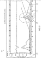
- FIG. 2 depicts an example graphical display of an output of a liquid chromatography process conducted at two different absorption wavelengths according to one embodiment.
- the illustrated embodiment depicts an example output display 200 of a liquid chromatography system such as the data processing apparatus 11 depicted in FIG. 1 .
- a liquid chromatography column was used and volume fractions data has been collected therefrom during a run of a liquid chromatography process using this column for two different absorbance wavelengths of light 230.
- absorbance wavelengths ⁇ 3 at 280 nanometers (nm) and wavelength ⁇ 4 and 525nm have been used for the run.
- a "volume fraction” is defined as the volume of a component of interest in a mixture divided by the volume of all components in the mixture. While “fractions” can be defined by the amount collected in various receptacles as output of the chromatograph, the "fractions” (e.g., of time of run or volume output) can also be designated arbitrarily or based on other criteria. That is, for the purposes of the techniques described herein, a “fraction” can be any arbitrary or variable volume of liquid that can be used to calculate a relative area of absorbance. Fractions can be of the same or different sizes as desired.
- the SI-unit is m 3 /m 3 .
- a plot of the absorbance wavelength ⁇ 3 is shown by line 225 and a plot of the absorbance wavelength ⁇ 4 is shown by line 215.
- the volume fractions data can then be processed by a liquid chromatography system and output onto display 200.
- the display 200 shows the plot of the volume fractions data for each of the absorbance wavelengths 230. Specifically, display 200 shows a plot of the amount of light absorbed by the mixture at the two absorbance wavelengths 230 for each volume fraction of the column.
- the y-axis 265 of the plot represents how much light was absorbed at the particular absorbance wavelength and the x-axis of the plot represents the volume fraction locations in millilitres.
- Display 200 further shows plots of the variables 240 used in this particular run of the liquid chromatography process.
- peaks of the absorbance wavelengths ⁇ 3 and ⁇ 4 are shown indicating when components of the mixture have flowed off the column at the various volume fractions. For instance, components that absorb light at ⁇ 3 exhibit peaks at 3.39 ml, 27.19 ml, and 46.98, and components that absorb light at ⁇ 4 exhibit a peak at 27.91. As can be seen, wavelengths ⁇ 3 and ⁇ 4 have peaks that coincide at 27.19 ml, which is shown by reference designator 225 in the figure. At volumes approximately between 24 ml and 30 ml in the column, the highest concentration of a component of interest flows off of the column.
- Systems and methods disclosed herein are adapted to analyze this data output from a liquid chromatography system to assist in determining which set of conditions and variables to apply to the process for optimal results.
- the systems and methods disclosed herein are adapted to analyze liquid chromatography data to assist in determining which volume fractions to pool together for optimal separation of the component of interest from impurities in the mixture. This can be accomplished by performing two or more runs of a liquid chromatography process while changing one variable between each run to determine which run provided more favorable results.
- normalization occurs by first defining a "fraction" (e.g., volume, time, etc.) and integrating the absorbance under the curve for that fraction size. The resulting integration value is then divided by the size of the fraction to normalize. This can be done for each absorbance wavelength. For instance, referring to FIG. 2 , a set of PQ values can be determined for ⁇ 3 and a set of PQ values can be determined for ⁇ 4.
- the set of PQ values therefore represents the resulting normalized curve that indicates the relative area of the component of interest in the mixture as a percentage divided by the total collected volume of the component for each volume fraction location.
- PQD purity quotient difference
- two different wavelengths or other attributes or variables can be monitored during a run of the liquid chromatography process on a mixture.
- absorbance at a first wavelength ⁇ 1 and a second wavelength ⁇ 2 can be monitored with a separate PQ value determined for each (PQ ⁇ 1 and PQ ⁇ 2).
- light being absorbed at a particular wavelength indicates the presence of a target molecule in the mixture.
- a target protein may absorb at a particular wavelength at which other proteins do not absorb.
- a second wavelength ⁇ 2 can be absorbed by a fraction representing an attribute shared by the target molecule (which absorbs at ⁇ 1, for example) and one or more other components of the mixture.
- wavelength ⁇ 2 could be 280 nm, a wavelength at which nearly all proteins absorb.
- wavelength ⁇ 2 can represent a component that is not desired (e.g., a component of the mixture to be excluded).
- the wavelength ⁇ 2 could be a wavelength at which DNA (or nucleic acids) absorbs, e.g., 255 nm.
- maximum PQD i.e., PQ ⁇ 1-PQ ⁇ 2
- PQ ⁇ 1-PQ ⁇ 2 the lowest proportion of target component, while having the least amount of undesired components (e.g., non-target proteins or contaminant DNA).
- wavelength ⁇ 1 can be the wavelength that the protein absorbs at ( e.g., 280 nm) and wavelength ⁇ 2 can be the wavelength that DNA or nucleic acids absorb at ( e.g., 255 nm).
- the PQD values indicate where the most overlap of DNA and protein occur in fractions.
- the PQ1 and PQ2 values can be used to compare different chromatography runs on the same column or between different columns.
- two runs of the liquid chromatography process can be run at two different times with the same set of variables. Comparison of different runs on the same column can be used to monitor column performance over time and can be used to indicate when the column has become degraded ( e.g., when the obtained PQD values significantly differ from a baseline set of PQD values).
- the second run of the liquid chromatography process can be used to screen for a different characteristic(s) by varying one or more variables from those used in the first run. This can allow for comparison of relative binding capacities or other chromatography attributes between columns.
- the first and second set of PQD values for the first and second runs of the liquid chromatography process can be displayed in a graphical display superimposed on each other at each of the volume fraction locations. This information can then be used to visually and quantifiably determine which set of the first or second set of PQD values provides a more favorable separation of the component of interest from impurities (or other components) in the mixture.
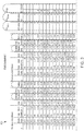
- FIG. 3 depicts a table showing example data for a PQD calculation for a liquid chromatography process conducted at two different absorption wavelengths ( ⁇ 3 and ⁇ 4) according to one embodiment.
- table 300 includes columns 301 and 303 for the total collected volume of the component of interest for each fraction location for the ⁇ 3 and ⁇ 4 wavelengths respectively, and includes columns 302 and 304 for the relative area of the component of interest in the mixture as a percentage for each fraction location for the ⁇ 3 and ⁇ 4 wavelengths respectively.
- Column 305 shows the set of PQ values for ⁇ 4
- column 310 shows the set of PQ values for ⁇ 3 for each fraction location.
- the difference between these sets of PQ values for wavelengths ⁇ 4 and ⁇ 3 can then be calculated to obtain a set of PQD values for this particular run of the liquid chromatography process.
- the PQD values are shown in column 315 of table 300. If the component of interest is known to absorb light at wavelength ⁇ 3, then the volume fractions where the component will flow off the column can be found by subtracting ⁇ 4 from ⁇ 3; and if the component of interest is instead known to absorb light at wavelength ⁇ 4, then the volume fractions where the component will flow off the column can be found by subtracting ⁇ 3 from ⁇ 4.
- PQD values greater than zero indicate there is more of the component of interest in the mixture than impurities for each volume fraction location and PQD values less than zero indicate there is more impurities in the mixture than the component of interest.
- PQD values equal to zero indicate equal amounts of impurities and of the component of interest in the mixture at each volume fraction location.
- the set of PQD values varies between 1 and -3.
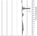
- plot 400 depicts an example plot of a set of PQD values for a liquid chromatography process at two different absorption wavelengths according to one embodiment.
- plot 400 includes a peak at reference designator 405, which represents a peak that occurred approximately between volume fraction locations A/73 and A/89. This is where the highest concentration of the component of interest flows off the column.
- Plot 400 also includes nulls at reference designators 401 and 410. These volume fraction locations are where the highest concentration of impurities flows off the column.
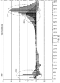
- FIG. 5 depicts an example plot of three sets of purity quotient difference values superimposed on each other for three separate runs of a liquid chromatography process at two different absorption wavelengths according to one embodiment.
- the set of PQD values shown in plot 500 represent a chromatography run for three different columns (or the same column with three different sets of variables).
- the set of PQD values calculated for these runs is displayed superimposed on each other at each of the volume fraction locations.
- the peaks at reference designators 501 (corresponding to the column 2 run) and 502 (corresponding to the column 1 run) provide the highest concentration of the component of interest as compared to impurities.
- the peak at reference designator 503 indicates the component of interest flowed out of column 3 too fast, and therefore, did not bind to the substrate. Therefore, column 2 in this example provided the best outcome.
- Column 1 also provided a good outcome, but the results from the run on column 3 should be ignored.
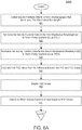
- FIG. 6A depicts an example flow chart of a process for analyzing liquid chromatography data according to one embodiment.
- process 600A begins at operation 601 where volume fractions data is collected from a liquid chromatography column for at least two absorbance wavelengths of light from a first run of a liquid chromatography process on a mixture.
- the liquid chromatography column is adapted to screen for a first characteristic of the mixture.
- the process includes collecting the chromatography data by performing a liquid chromatography run on a mixture to generate the data; in other embodiments, the chromatography data is provided from other sources.
- Process 600A continues at operation 603 where the relative peak area for the first volume of the component of interest in the mixture for the first absorbance wavelengths ( ⁇ 1) is normalized to obtain a first set of purity quotient ("PQ") values PQ1.
- the set of PQ values can be normalized for a volume by dividing the first relative peak area of the component of interest by the total collected volume of the component in the mixture at each volume fraction location of the first volume.
- the second relative peak area for the first volume of the component of interest in the mixture is also normalized for the second absorbance wavelength ( ⁇ 2) to obtain a second set of purity quotient values PQ2.
- the difference between values PQ1 and PQ2 is calculated for each volume fraction location of the first and second volumes to obtain a first set of purity quotient difference ("PQD") values for the first run of the liquid chromatography process at operation 607, which are displayed in a graphical display at operation 609.
- PQD purity quotient difference
- any type of graphical display can be used as is well known in the art. From this information, it can then be determined which volume fractions to pool together based on the display of the first set of PQD values (operation 611). This completes process 600A according to one example embodiment.
- FIG. 6B depicts an example flow chart of a further process for analyzing liquid chromatography data according to one embodiment.
- process 600B begins at operation 613 where volume fractions data from a liquid chromatography column is collected for the two absorbance wavelengths from a second run of the liquid chromatography process on the mixture.
- This liquid chromatography process is adapted for a second characteristic of the mixture.
- One or more variables of the liquid chromatography process are varied in the second run.
- modifying one of the variables for each subsequent run can be used to determine the best set of conditions ( i.e., which variables to use) to obtain optimum separation of the component of interest from impurities in the mixture.
- Process 600B continues at operation 615 where the relative peak area for a second volume of the component of interest in the mixture is normalized for the first absorbance wavelength ⁇ 1 to obtain a third set of purity quotient values PQ3. And at operation 617, the relative peak area for the second volume of the component of interest in the mixture is normalized for the second absorbance wavelength ⁇ 2 to obtain a fourth set of purity quotient values PQ4. The difference between PQ3 and PQ4 is calculated for each volume fraction location to obtain a second set of PQD values (operation 619). The first and second sets of PQD values for the first and second runs of the liquid chromatography process are then displayed superimposed on each other for each volume fraction location at operation 621. In one embodiment, a two-dimensional representation of the first and second sets of PQD values can be displayed based on the first and second runs of the liquid chromatography process on the mixture.
- This information can then be used to determine which of the first or second sets of PQD values provides a more favorable separation of the component of interest from impurities in the mixture based on the first and second sets of PQD values (operation 623).
- Multiple runs of the liquid chromatography process can be performed to further refine the analysis to determine which set of conditions provide the best results.
- the results of multiple runs can be compared to determine how to optimally set one or more variables of the process.
- multiple runs can be performed where one or more variables of the liquid chromatography process can be varied to determine which variables, as well as which values of those variables, can be used in the liquid chromatography process to provide optimal separation of the component of interest from the mixture. Examples of some of the types of variables that can be varied include column type, pH of the mobile phase liquid, conductivity of the mobile phase liquid, and flow rate of the mobile phase liquid.
- three or more runs of the liquid chromatography process can be performed on the mixture where one variable is modified for each additional run.
- the PQD values can then be displayed in three or more dimensions based on the three or more runs of the liquid chromatography process respectively.
- PQ values for the component of interest can be subtracted from PQ values of other components in the mixture to identify volume fractions where the highest concentration of the component of interest can be excluded.
- the liquid chromatography process can be applied to any absorbance wavelength that can be measured by a spectrophotometric detector.
- the relative area values can be obtained from a detector that is external to the liquid chromatography system (e.g., fluorescence, refractive index, etc.).
- the peak relative area for the volume of the component of interest in the mixture can be normalized in different ways to produce the same results. For instance, the peak relative area for a can be normalized with respect to: the total volume of the component of interest in the mixture; the volume of the column in the liquid chromatography process; or with respect to time. Other embodiments are possible. This completes process 600 according to one example embodiment.
- FIGs . 6A and 6B provide a particular process for analyzing liquid chromatography data according to one embodiment. Other sequences of operations may also be performed according to alternative embodiments. For example, alternative embodiments may perform the operations outlined above in a different order and additional operations may be added or removed depending on the particular applications. Moreover, the individual operations may include one or more sub-operations that may be performed in various sequences as appropriate.
- a liquid chromatography run could go without collecting any liquid in tubes ("fractions") and an arbitrary fraction volume could instead be set where software could go along from start to finish and calculate relative areas of the arbitrary fraction volume.
- This arbitrary "fraction” can also be performed with respect to volume, time, or column volume.
- FIG. 7 depicts an example block diagram of a data processing system upon which the disclosed embodiments may be implemented.
- Embodiments of the present invention may be practiced with various computer system configurations such as hand-held devices, microprocessor systems, microprocessor-based or programmable user electronics, minicomputers, mainframe computers and the like.
- the embodiments can also be practiced in distributed computing environments where tasks are performed by remote processing devices that are linked through a wire-based or wireless network.
- FIG. 7 shows one example of a data processing system, such as data processing system 700, which may be used with the present described embodiments. Note that while FIG. 7 illustrates various components of a data processing system, it is not intended to represent any particular architecture or manner of interconnecting the components as such details are not germane to the techniques described herein.
- the data processing system of FIG. 7 may, for example, a personal computer (PC), workstation, tablet, smartphone or other hand-held wireless device, or any device having similar functionality.
- PC personal computer
- workstation tablet
- smartphone hand-held wireless device
- the data processing system 701 includes a system bus 702 which is coupled to a microprocessor 703, a Read-Only Memory (ROM) 707, a volatile Random Access Memory (RAM) 705, as well as other nonvolatile memory 706.
- microprocessor 703 is coupled to cache memory 704.
- System bus 702 can be adapted to interconnect these various components together and also interconnect components 703, 707, 705, and 706 to a display controller and display device 708, and to peripheral devices such as input/output (“I/O") devices 710.
- I/O devices 710 are coupled to the system bus 702 through I/O controllers 709.
- the I/O controller 709 includes a Universal Serial Bus (“USB”) adapter for controlling USB peripherals or other type of bus adapter.
- USB Universal Serial Bus
- RAM 705 can be implemented as dynamic RAM ("DRAM") which requires power continually in order to refresh or maintain the data in the memory.
- the other nonvolatile memory 706 can be a magnetic hard drive, magnetic optical drive, optical drive, DVD RAM, or other type of memory system that maintains data after power is removed from the system. While FIG. 7 shows that nonvolatile memory 706 as a local device coupled with the rest of the components in the data processing system, it will be appreciated by skilled artisans that the described techniques may use a nonvolatile memory remote from the system, such as a network storage device coupled with the data processing system through a network interface such as a modem or Ethernet interface (not shown).
- a network storage device coupled with the data processing system through a network interface such as a modem or Ethernet interface (not shown).
- a computer apparatus or data processing system may comprise a processor and a memory coupled with the processor, the memory adapted to store instructions to be executed by the processor for analyzing liquid chromatograph data as described herein.
- embodiments can employ various computer-implemented functions involving data stored in a data processing system. That is, the techniques may be carried out in a computer or other data processing system in response executing sequences of instructions stored in memory.
- hardwired circuitry may be used independently, or in combination with software instructions, to implement these techniques. For instance, the described functionality may be performed by specific hardware components containing hardwired logic for performing operations, or by any combination of custom hardware components and programmed computer components. The techniques described herein are not limited to any specific combination of hardware circuitry and software.
- Embodiments herein may also be in the form of computer code stored on a computer-readable medium.
- Computer-readable media can also be adapted to store computer instructions, which when executed by a computer or other data processing system, such as data processing system 700, are adapted to cause the system to perform operations according to the techniques described herein.
- Computer-readable media can include any mechanism that stores information in a form accessible by a data processing device such as a computer, network device, tablet, smartphone, or any device having similar functionality.
- Examples of computer-readable media include any type of tangible article of manufacture capable of storing information thereon such as a hard drive, floppy disk, DVD, CD-ROM, magnetic-optical disk, ROM, RAM, EPROM, EEPROM, flash memory and equivalents thereto, a magnetic or optical card, or any type of media suitable for storing electronic data.
- Computer-readable media can also be distributed over a network-coupled computer system, which can be stored or executed in a distributed fashion.
Landscapes
- Physics & Mathematics (AREA)
- Health & Medical Sciences (AREA)
- Life Sciences & Earth Sciences (AREA)
- General Health & Medical Sciences (AREA)
- Analytical Chemistry (AREA)
- Chemical & Material Sciences (AREA)
- Biochemistry (AREA)
- General Physics & Mathematics (AREA)
- Immunology (AREA)
- Pathology (AREA)
- Engineering & Computer Science (AREA)
- Bioinformatics & Cheminformatics (AREA)
- Library & Information Science (AREA)
- Biophysics (AREA)
- Molecular Biology (AREA)
- Proteomics, Peptides & Aminoacids (AREA)
- Bioinformatics & Computational Biology (AREA)
- Biotechnology (AREA)
- Evolutionary Biology (AREA)
- Medical Informatics (AREA)
- Spectroscopy & Molecular Physics (AREA)
- Theoretical Computer Science (AREA)
- Genetics & Genomics (AREA)
- Investigating Or Analysing Materials By Optical Means (AREA)
- Treatment Of Liquids With Adsorbents In General (AREA)
Claims (15)
- Verfahren zum Analysieren von Flüssigchromatographiedaten, umfassend:mit einem Datenverarbeitungssystem Sammeln erster Volumenfraktionsdaten von einer ersten Flüssigchromatographiesäule für eine erste Absorptionswellenlänge von Licht λ1 aus einem ersten Durchlauf eines Flüssigchromatographieverfahrens mit einem Gemisch, wobei die erste Flüssigchromatographiesäule auf ein erstes Merkmal des Gemischs prüft, wobei eine Volumenfraktion das Volumen einer interessierenden Komponente in einem Gemisch, dividiert durch das Volumen aller Komponenten in dem Gemisch, ist;Normieren einer ersten relativen Peakfläche für ein erstes Volumen einer interessierenden Komponente in dem Gemisch für die erste Absorptionswellenlänge λ1, wobei man eine erste Menge von Reinheitsquotientwerten PQ1 erhält;mit dem Datenverarbeitungssystem Sammeln zweiter Volumenfraktionsdaten von einer zweiten Flüssigchromatographiesäule für eine zweite Absorptionswellenlänge von Licht λ2 aus einem zweiten Durchlauf eines Flüssigchromatographieverfahrens mit dem Gemisch, wobei die zweite Flüssigchromatographiesäule auf ein zweites Merkmal des Gemischs prüft;Normieren einer zweiten relativen Peakfläche für das zweite Volumen der interessierenden Komponente in dem Gemisch für die zweite Absorptionswellenlänge λ2, wobei man eine zweite Menge von Reinheitsquotientwerten PQ2 erhält;Speichern der Werte PQ1 und PQ2 in einem Speicher;mit dem Datenverarbeitungssystem Berechnen einer Differenz zwischen den Werten PQ1 und PQ2 für jeden Volumenfraktionsort des ersten und des zweiten Volumens, wobei man eine erste Menge von Reinheitsquotientdifferenz("PQD")-Werten erhält, wobei eine Fraktion jedes willkürliche oder variable Flüssigkeitsvolumen ist, das verwendet werden kann, um eine relative Fläche der Extinktion zu berechnen;Anzeigen der ersten Menge von PQD-Werten in einer graphischen Anzeige; undBestimmen, welche Volumenfraktionen zu vereinigen sind, auf der Basis der Anzeige der ersten Menge von PQD-Werten.
- Verfahren gemäß Anspruch 1, wobei(i) der erste und der zweite Flüssigchromatographiedurchlauf derselbe Flüssigchromatographiedurchlauf sind, wobei die interessierende Komponente bei beiden Wellenlängen λ1 und λ2 absorbiert und wobei die interessierende Komponente von Verunreinigungen, die ebenfalls bei der Wellenlänge λ2 absorbieren, getrennt wird, indem man die Werte PQ1 bei der Wellenlänge λ1 von den Werten PQ2 bei der Wellenlänge λ2 subtrahiert; oder(ii) der erste und der zweite Flüssigchromatographiedurchlauf derselbe Flüssigchromatographiedurchlauf sind, wobei die interessierende Komponente bei der Wellenlänge λ1 absorbiert und ein bekannter Kontaminationsstoff bei einer Wellenlänge λ2 absorbiert und wobei die interessierende Komponente von dem Kontaminationsstoff getrennt wird, indem man die Werte PQ2 bei Wellenlänge λ2 von den Werten PQ1 bei der Wellenlänge λ1 subtrahiert; oder(iii) der erste und der zweite Flüssigchromatographiedurchlauf derselbe Flüssigchromatographiedurchlauf sind, wobei die interessierende Komponente bei der Wellenlänge λ1 absorbiert und auch an DNA bindet, die bei der Wellenlänge λ2 absorbiert, und wobei die Werte PQ1 bei der Wellenlänge λ1 von den Werten PQ2 bei der Wellenlänge λ2 subtrahiert werden können, um Orte zu identifizieren, wo es eine maximale Überlappung zwischen DNA und Protein gibt.
- Verfahren gemäß Anspruch 1, wobei der erste und der zweite Flüssigchromatographiedurchlauf verschiedene Durchläufe sind und die Wellenlängen λ1 und λ2 für beide verschiedenen Durchläufe dieselbe Wellenlänge sind und wobei die interessierende Komponente bei dieser Wellenlänge absorbiert.
- Verfahren gemäß Anspruch 3, wobei(i) die erste und die zweite Säule dieselbe Säule sind und die Leistung der Säule zwischen Durchläufen dadurch bestimmt wird, dass man die Werte PQ1 von PQ2 subtrahiert; oder(ii) die erste und die zweite Säule verschiedene Säulen sind und die vergleichende Leistung der ersten und der zweiten Säule dadurch bestimmt wird, dass man die Werte PQ1 von PQ2 subtrahiert.
- Verfahren gemäß Anspruch 1, weiterhin umfassend:mit dem Datenverarbeitungssystem Sammeln dritter Volumenfraktionsdaten von einer dritten Flüssigchromatographiesäule für die zwei Absorptionswellenlängen λ1 und λ2 aus einem dritten Durchlauf des Flüssigchromatographieverfahrens mit dem Gemisch, wobei die dritte Flüssigchromatographiesäule auf ein zweites Merkmal des Gemischs, das von dem ersten Merkmal verschieden ist, prüft;Normieren einer dritten relativen Peakfläche für ein drittes Volumen der interessierenden Komponente in dem Gemisch für die erste Absorptionswellenlänge λ1, wobei man eine dritte Menge von Reinheitsquotientwerten PQ3 erhält;Normieren einer vierten relativen Peakfläche für ein viertes Volumen der interessierenden Komponente in dem Gemisch für die zweite Absorptionswellenlänge λ2, wobei man eine vierte Menge von Reinheitsquotientwerten PQ4 erhält;Speichern der Werte PQ3 und PQ4 in dem Speicher;mit dem Datenverarbeitungssystem Berechnen einer Differenz zwischen PQ3 und PQ4 für jeden Volumenfraktionsort, wobei man eine zweite Menge von PQD-Werten erhält;Anzeigen der ersten und der zweiten Menge von PQD-Werten für den ersten und den zweiten Durchlauf des Flüssigchromatographieverfahrens, die für jeden Volumenfraktionsort übereinandergelegt sind, in einer graphischen Anzeige; undBestimmen, welche der ersten oder zweiten Mengen von PQD-Werten für eine günstigere Trennung der interessierenden Komponente von Verunreinigungen in dem Gemisch auf der Basis der ersten und der zweiten Menge von PQD-Werten sorgt.
- Verfahren gemäß Anspruch 1, wobei PQ-Werte dadurch normiert werden, dass man die erste relative Peakfläche der interessierenden Komponente durch ein gesammeltes Gesamtvolumen der Komponente in dem Gemisch an jedem Volumenfraktionsort des ersten Volumens dividiert, wobei vorzugsweise eine zweidimensionale Darstellung der ersten und der zweiten Menge von PQD-Werten angezeigt wird.
- Verfahren gemäß Anspruch 1, weiterhin umfassend:Durchführen von drei oder mehr Durchläufen des Flüssigchromatographieverfahrens mit dem Gemisch, wobei in jedem zusätzlichen Durchlauf des Verfahrens eine Variable des Flüssigchromatographieverfahrens variiert wird; undAnzeigen einer Darstellung von PQD-Werten in drei oder mehr Dimensionen jeweils auf der Basis der drei oder mehr Durchläufe des Flüssigchromatographieverfahrens.
- Verfahren gemäß Anspruch 1, wobei mehrere Durchläufe des Flüssigchromatographieverfahrens miteinander verglichen werden, um zu bestimmen, wie man eine oder mehrere Variablen des Verfahrens optimal einstellt, wobei vorzugsweise die Variablen in dem Flüssigchromatographieverfahren die Art der Säule, den pH-Wert der Flüssigkeit der mobilen Phase, die Leitfähigkeit der Flüssigkeit der mobilen Phase und die Fließgeschwindigkeit der Flüssigkeit der mobilen Phase umfassen.
- Verfahren gemäß Anspruch 1, wobei das Flüssigchromatographieverfahren so betrieben werden kann, dass es sich auf jede Absorptionswellenlänge anwenden lässt, die mit einem spektrophotometrischen Detektor gemessen werden kann.
- Verfahren gemäß Anspruch 1, wobei das Normieren der ersten und zweiten relativen Peakfläche für das erste und zweite Volumen das Normieren bezüglich des Gesamtvolumens der interessierenden Komponente in dem Gemisch umfasst.
- Verfahren gemäß Anspruch 1, wobei das Normieren der ersten und zweiten relativen Peakfläche für das erste und zweite Volumen das Normieren bezüglich des Säulenvolumens umfasst.
- Verfahren gemäß Anspruch 1, wobei das Normieren der ersten und zweiten relativen Peakfläche für das erste und zweite Volumen das Normieren bezüglich der Zeit umfasst.
- Verfahren gemäß Anspruch 1, wobei die interessierende Komponente in dem Gemisch ausschließlich Licht einer bestimmten Wellenlänge absorbiert.
- System zum Analysieren von Flüssigchromatographiedaten, umfassend:einen Prozessor;einen mit dem Prozessor gekoppelten Speicher, wobei der Speicher speziell so gestaltet ist, dass er Flüssigchromatographiedaten speichern kann, und wobei in dem Speicher Anweisungen gespeichert sind, die von dem Prozessor auszuführen sind, um die Flüssigchromatographiedaten zu analysieren, wobei die Anweisungen, wenn sie von dem Prozessor ausgeführt werden, bewirken, dass das System:erste Volumenfraktionsdaten von einer ersten Flüssigchromatographiesäule für eine erste Absorptionswellenlänge von Licht λ1 aus einem ersten Durchlauf eines Flüssigchromatographieverfahrens mit einem Gemisch sammelt, wobei eine Volumenfraktion das Volumen einer interessierenden Komponente in einem Gemisch, dividiert durch das Volumen aller Komponenten in dem Gemisch, ist;eine erste relative Peakfläche für ein erstes Volumen einer interessierenden Komponente in dem Gemisch für die erste Absorptionswellenlänge λ1 normiert, wobei man eine erste Menge von Reinheitsquotientwerten PQ1 erhält;zweite Volumenfraktionsdaten von einer zweiten Flüssigchromatographiesäule für eine zweite Absorptionswellenlänge von Licht λ2 aus einem zweiten Durchlauf eines Flüssigchromatographieverfahrens mit dem Gemisch sammelt, wobei die zweite Flüssigchromatographiesäule auf ein zweites Merkmal des Gemischs prüft;eine zweite relative Peakfläche für das zweite Volumen der interessierenden Komponente in dem Gemisch für die zweite Absorptionswellenlänge λ2 normiert, wobei man eine zweite Menge von Reinheitsquotientwerten PQ2 erhält;die Werte PQ1 und PQ2 in dem Speicher speichert;mit dem Prozessor eine Differenz zwischen den Werten PQ1 und PQ2 für jeden Volumenfraktionsort des ersten und des zweiten Volumens berechnet, wobei man eine erste Menge von Reinheitsquotientdifferenz("PQD")-Werten erhält, wobei eine Fraktion jedes willkürliche oder variable Flüssigkeitsvolumen ist, das verwendet werden kann, um eine relative Fläche der Extinktion zu berechnen;die erste Menge von PQD-Werten in einer graphischen Anzeige anzeigt; undauf der Basis der Anzeige der ersten Menge von PQD-Werten bestimmt, welche Volumenfraktionen zu vereinigen sind.
- System gemäß Anspruch 14, wobei der erste und der zweite Flüssigchromatographiedurchlauf derselbe Flüssigchromatographiedurchlauf sind, wobei die interessierende Komponente bei beiden Wellenlängen λ1 und λ2 absorbiert und wobei die interessierende Komponente von Verunreinigungen, die ebenfalls bei der Wellenlänge λ2 absorbieren, getrennt wird, indem man die Werte PQ1 bei der Wellenlänge λ1 von den Werten PQ2 bei der Wellenlänge λ2 subtrahiert.
Applications Claiming Priority (3)
| Application Number | Priority Date | Filing Date | Title |
|---|---|---|---|
| US201461927206P | 2014-01-14 | 2014-01-14 | |
| US14/592,308 US10261058B2 (en) | 2014-01-14 | 2015-01-08 | Method and system for liquid chromatography data analysis |
| PCT/US2015/010760 WO2015108771A1 (en) | 2014-01-14 | 2015-01-09 | Method for liquid chromatography data analysis |
Publications (3)
| Publication Number | Publication Date |
|---|---|
| EP2986352A1 EP2986352A1 (de) | 2016-02-24 |
| EP2986352A4 EP2986352A4 (de) | 2016-11-09 |
| EP2986352B1 true EP2986352B1 (de) | 2020-04-01 |
Family
ID=53521160
Family Applications (1)
| Application Number | Title | Priority Date | Filing Date |
|---|---|---|---|
| EP15737791.2A Not-in-force EP2986352B1 (de) | 2014-01-14 | 2015-01-09 | Verfahren für flüssigkeitschromatografiedatenanalyse |
Country Status (4)
| Country | Link |
|---|---|
| US (1) | US10261058B2 (de) |
| EP (1) | EP2986352B1 (de) |
| CN (1) | CN105473203B (de) |
| WO (1) | WO2015108771A1 (de) |
Families Citing this family (8)
| Publication number | Priority date | Publication date | Assignee | Title |
|---|---|---|---|---|
| CN105374265B (zh) * | 2015-12-15 | 2018-05-22 | 徐州医学院 | 一种高效液相色谱仪实验教学模型及实验方法 |
| JP6508414B2 (ja) * | 2016-03-01 | 2019-05-08 | 株式会社島津製作所 | クロマトグラフ装置 |
| GB201709531D0 (en) * | 2017-06-15 | 2017-08-02 | Ge Healthcare Bio Sciences Ab | Method and apparatus for determining one or more buffer composition recipes |
| BR112020000978A2 (pt) * | 2017-09-08 | 2020-07-14 | Regeneron Pharmaceuticals, Inc. | método para determinar uma razão de fármaco para anticorpo em uma amostra compreendendo um conjugado anticorpo-fármaco. |
| US11095587B2 (en) * | 2018-06-08 | 2021-08-17 | Waters Technologies Ireland Limited | Techniques for handling messages in laboratory informatics |
| EP4488677A3 (de) * | 2019-05-24 | 2025-04-16 | Sartorius Stedim Biotech GmbH | Chromatografieverfahren, verfahren zur bestimmung der konzentration von mindestens einer verbindung in einem chromatografieverfahren und verfahren zur gewinnung von mindestens einem chromatografieverfahrensparameter |
| WO2022081587A1 (en) * | 2020-10-12 | 2022-04-21 | Leco Corporation | Unresolved complex mixture separation of data collected in two-dimensional gas chromatography |
| CN113311081B (zh) * | 2021-05-17 | 2023-08-11 | 清华大学 | 基于三维液相色谱指纹的污染源识别方法及装置 |
Family Cites Families (10)
| Publication number | Priority date | Publication date | Assignee | Title |
|---|---|---|---|---|
| US4631687A (en) * | 1983-11-03 | 1986-12-23 | Rohrback Technology Corporation | Method and apparatus for analysis employing multiple separation processes |
| US5126270A (en) | 1984-08-07 | 1992-06-30 | Carnegie-Mellon University | Enzyme amplification and purification |
| US5522988A (en) | 1985-01-25 | 1996-06-04 | The Dow Chemical Company | On-line coupled liquid and gas chromatography system with an interface capillary tube interposed between a pair of capillary chromatographic columns |
| US20030224354A1 (en) | 2002-05-30 | 2003-12-04 | Introgen Therapeutics Inc. | Quantifying viral particles with intrinsic fluorescence |
| US20040126892A1 (en) | 2002-09-20 | 2004-07-01 | Bogomolov Andrey Yurievich | Methods for characterizing a mixture of chemical compounds |
| EP1544612A1 (de) | 2003-12-09 | 2005-06-22 | Agilent Technologies, Inc. | Chromatographisches System und Verfahren zur Operation desselben |
| WO2008058349A1 (en) | 2006-11-17 | 2008-05-22 | Gareth Michael Forde | Materials, methods and systems for purification and/or seperation |
| WO2009018307A2 (en) | 2007-07-31 | 2009-02-05 | Wyeth | Analysis of polypeptide production |
| US10386346B2 (en) | 2011-09-05 | 2019-08-20 | Shimadzu Corporation | System and method for processing chromatogram data |
| JP6156501B2 (ja) * | 2013-09-02 | 2017-07-05 | 株式会社島津製作所 | クロマトグラムデータ処理装置 |
-
2015
- 2015-01-08 US US14/592,308 patent/US10261058B2/en not_active Expired - Fee Related
- 2015-01-09 EP EP15737791.2A patent/EP2986352B1/de not_active Not-in-force
- 2015-01-09 CN CN201580000866.5A patent/CN105473203B/zh not_active Expired - Fee Related
- 2015-01-09 WO PCT/US2015/010760 patent/WO2015108771A1/en not_active Ceased
Non-Patent Citations (1)
| Title |
|---|
| None * |
Also Published As
| Publication number | Publication date |
|---|---|
| EP2986352A1 (de) | 2016-02-24 |
| WO2015108771A1 (en) | 2015-07-23 |
| CN105473203A (zh) | 2016-04-06 |
| US20150198573A1 (en) | 2015-07-16 |
| US10261058B2 (en) | 2019-04-16 |
| CN105473203B (zh) | 2018-01-30 |
| EP2986352A4 (de) | 2016-11-09 |
Similar Documents
| Publication | Publication Date | Title |
|---|---|---|
| EP2986352B1 (de) | Verfahren für flüssigkeitschromatografiedatenanalyse | |
| US11460455B2 (en) | Method and system for determining the influence of experimental parameters on a liquid chromatography protocol | |
| Gargano et al. | Reducing dilution and analysis time in online comprehensive two-dimensional liquid chromatography by active modulation | |
| Maya et al. | Automated in-syringe dispersive liquid-liquid microextraction | |
| Vajda et al. | Modifier adsorption in supercritical fluid chromatography onto silica surface | |
| JP7216225B2 (ja) | クロマトグラムデータ処理装置、クロマトグラムデータ処理方法、クロマトグラムデータ処理プログラム及び記憶媒体 | |
| JP2016510900A (ja) | クロマトグラフィーシステムの校正方法 | |
| Delahaye et al. | Implementing stationary-phase optimized selectivity in supercritical fluid chromatography | |
| Hahn et al. | Calibration‐free inverse modeling of ion‐exchange chromatography in industrial antibody purification | |
| JP2017534891A (ja) | 液体クロマトグラフィー精製を実施するための方法および装置 | |
| Mondello et al. | Comprehensive two-dimensional liquid chromatography | |
| Kwiatkowski et al. | Application of displacement chromatography to online two-dimensional liquid chromatography coupled to tandem mass spectrometry improves peptide separation efficiency and detectability for the analysis of complex proteomes | |
| Bhalerao et al. | Advances, applications, and challenges in RP HPLC method development | |
| Schneider et al. | Systematic investigation of the sorption properties of Tenax TA, Chromosorb 106, Porapak N, and Carbopak F | |
| Nell et al. | Advances in online comprehensive two-dimensional liquid chromatography method development | |
| Kifle et al. | Impregnation and characterization of high performance extraction columns for separation of metal ions | |
| Szucs et al. | Liquid chromatography in the pharmaceutical industry | |
| Bielicka-Daszkiewicz | Extraction techniques based on solid state and connected with liquid chromatography | |
| Samuelsson et al. | Highlighting important parameters often neglected in numerical optimization of preparative chromatography | |
| JP7782309B2 (ja) | 分取液体クロマトグラフ装置及び分取条件決定支援方法 | |
| Baczek | Computer-assisted optimization of liquid chromatography separations of drugs and related substances | |
| Ferguson et al. | Green analytical chemistry | |
| Chen et al. | UHPLC method development | |
| Altern | Mechanistic modeling of multimodal chromatography: from first-principles to principal applications | |
| Hendriks | Theoretical models in LC based bioanalytical method development |
Legal Events
| Date | Code | Title | Description |
|---|---|---|---|
| PUAI | Public reference made under article 153(3) epc to a published international application that has entered the european phase |
Free format text: ORIGINAL CODE: 0009012 |
|
| 17P | Request for examination filed |
Effective date: 20151118 |
|
| AK | Designated contracting states |
Kind code of ref document: A1 Designated state(s): AL AT BE BG CH CY CZ DE DK EE ES FI FR GB GR HR HU IE IS IT LI LT LU LV MC MK MT NL NO PL PT RO RS SE SI SK SM TR |
|
| AX | Request for extension of the european patent |
Extension state: BA ME |
|
| A4 | Supplementary search report drawn up and despatched |
Effective date: 20161012 |
|
| RIC1 | Information provided on ipc code assigned before grant |
Ipc: B01D 15/08 20060101ALI20161006BHEP Ipc: G01N 30/46 20060101ALN20161006BHEP Ipc: G01N 30/86 20060101AFI20161006BHEP Ipc: G01N 30/74 20060101ALN20161006BHEP Ipc: C07K 1/16 20060101ALI20161006BHEP Ipc: G01N 1/18 20060101ALI20161006BHEP |
|
| DAX | Request for extension of the european patent (deleted) | ||
| STAA | Information on the status of an ep patent application or granted ep patent |
Free format text: STATUS: EXAMINATION IS IN PROGRESS |
|
| 17Q | First examination report despatched |
Effective date: 20170526 |
|
| RIC1 | Information provided on ipc code assigned before grant |
Ipc: G01N 30/86 20060101AFI20190726BHEP Ipc: G01N 1/18 20060101ALI20190726BHEP Ipc: G01N 30/46 20060101ALN20190726BHEP Ipc: B01D 15/08 20060101ALI20190726BHEP Ipc: G01N 30/74 20060101ALN20190726BHEP Ipc: C07K 1/16 20060101ALI20190726BHEP |
|
| REG | Reference to a national code |
Ref country code: DE Ref legal event code: R079 Ref document number: 602015049829 Country of ref document: DE Free format text: PREVIOUS MAIN CLASS: B01D0015080000 Ipc: G01N0030860000 |
|
| GRAP | Despatch of communication of intention to grant a patent |
Free format text: ORIGINAL CODE: EPIDOSNIGR1 |
|
| STAA | Information on the status of an ep patent application or granted ep patent |
Free format text: STATUS: GRANT OF PATENT IS INTENDED |
|
| RIC1 | Information provided on ipc code assigned before grant |
Ipc: G01N 1/18 20060101ALI20190924BHEP Ipc: G01N 30/46 20060101ALN20190924BHEP Ipc: G01N 30/86 20060101AFI20190924BHEP Ipc: C07K 1/16 20060101ALI20190924BHEP Ipc: G01N 30/74 20060101ALN20190924BHEP Ipc: B01D 15/08 20060101ALI20190924BHEP |
|
| INTG | Intention to grant announced |
Effective date: 20191009 |
|
| RIN1 | Information on inventor provided before grant (corrected) |
Inventor name: HABEL, JEFF |
|
| GRAS | Grant fee paid |
Free format text: ORIGINAL CODE: EPIDOSNIGR3 |
|
| GRAA | (expected) grant |
Free format text: ORIGINAL CODE: 0009210 |
|
| STAA | Information on the status of an ep patent application or granted ep patent |
Free format text: STATUS: THE PATENT HAS BEEN GRANTED |
|
| AK | Designated contracting states |
Kind code of ref document: B1 Designated state(s): AL AT BE BG CH CY CZ DE DK EE ES FI FR GB GR HR HU IE IS IT LI LT LU LV MC MK MT NL NO PL PT RO RS SE SI SK SM TR |
|
| REG | Reference to a national code |
Ref country code: GB Ref legal event code: FG4D |
|
| REG | Reference to a national code |
Ref country code: AT Ref legal event code: REF Ref document number: 1252025 Country of ref document: AT Kind code of ref document: T Effective date: 20200415 Ref country code: CH Ref legal event code: EP |
|
| REG | Reference to a national code |
Ref country code: DE Ref legal event code: R096 Ref document number: 602015049829 Country of ref document: DE |
|
| REG | Reference to a national code |
Ref country code: IE Ref legal event code: FG4D |
|
| PG25 | Lapsed in a contracting state [announced via postgrant information from national office to epo] |
Ref country code: BG Free format text: LAPSE BECAUSE OF FAILURE TO SUBMIT A TRANSLATION OF THE DESCRIPTION OR TO PAY THE FEE WITHIN THE PRESCRIBED TIME-LIMIT Effective date: 20200701 |
|
| REG | Reference to a national code |
Ref country code: NL Ref legal event code: MP Effective date: 20200401 |
|
| REG | Reference to a national code |
Ref country code: LT Ref legal event code: MG4D |
|
| PG25 | Lapsed in a contracting state [announced via postgrant information from national office to epo] |
Ref country code: PT Free format text: LAPSE BECAUSE OF FAILURE TO SUBMIT A TRANSLATION OF THE DESCRIPTION OR TO PAY THE FEE WITHIN THE PRESCRIBED TIME-LIMIT Effective date: 20200817 Ref country code: CZ Free format text: LAPSE BECAUSE OF FAILURE TO SUBMIT A TRANSLATION OF THE DESCRIPTION OR TO PAY THE FEE WITHIN THE PRESCRIBED TIME-LIMIT Effective date: 20200401 Ref country code: LT Free format text: LAPSE BECAUSE OF FAILURE TO SUBMIT A TRANSLATION OF THE DESCRIPTION OR TO PAY THE FEE WITHIN THE PRESCRIBED TIME-LIMIT Effective date: 20200401 Ref country code: NO Free format text: LAPSE BECAUSE OF FAILURE TO SUBMIT A TRANSLATION OF THE DESCRIPTION OR TO PAY THE FEE WITHIN THE PRESCRIBED TIME-LIMIT Effective date: 20200701 Ref country code: IS Free format text: LAPSE BECAUSE OF FAILURE TO SUBMIT A TRANSLATION OF THE DESCRIPTION OR TO PAY THE FEE WITHIN THE PRESCRIBED TIME-LIMIT Effective date: 20200801 Ref country code: GR Free format text: LAPSE BECAUSE OF FAILURE TO SUBMIT A TRANSLATION OF THE DESCRIPTION OR TO PAY THE FEE WITHIN THE PRESCRIBED TIME-LIMIT Effective date: 20200702 Ref country code: FI Free format text: LAPSE BECAUSE OF FAILURE TO SUBMIT A TRANSLATION OF THE DESCRIPTION OR TO PAY THE FEE WITHIN THE PRESCRIBED TIME-LIMIT Effective date: 20200401 Ref country code: SE Free format text: LAPSE BECAUSE OF FAILURE TO SUBMIT A TRANSLATION OF THE DESCRIPTION OR TO PAY THE FEE WITHIN THE PRESCRIBED TIME-LIMIT Effective date: 20200401 Ref country code: NL Free format text: LAPSE BECAUSE OF FAILURE TO SUBMIT A TRANSLATION OF THE DESCRIPTION OR TO PAY THE FEE WITHIN THE PRESCRIBED TIME-LIMIT Effective date: 20200401 |
|
| REG | Reference to a national code |
Ref country code: AT Ref legal event code: MK05 Ref document number: 1252025 Country of ref document: AT Kind code of ref document: T Effective date: 20200401 |
|
| PG25 | Lapsed in a contracting state [announced via postgrant information from national office to epo] |
Ref country code: HR Free format text: LAPSE BECAUSE OF FAILURE TO SUBMIT A TRANSLATION OF THE DESCRIPTION OR TO PAY THE FEE WITHIN THE PRESCRIBED TIME-LIMIT Effective date: 20200401 Ref country code: RS Free format text: LAPSE BECAUSE OF FAILURE TO SUBMIT A TRANSLATION OF THE DESCRIPTION OR TO PAY THE FEE WITHIN THE PRESCRIBED TIME-LIMIT Effective date: 20200401 Ref country code: LV Free format text: LAPSE BECAUSE OF FAILURE TO SUBMIT A TRANSLATION OF THE DESCRIPTION OR TO PAY THE FEE WITHIN THE PRESCRIBED TIME-LIMIT Effective date: 20200401 |
|
| PG25 | Lapsed in a contracting state [announced via postgrant information from national office to epo] |
Ref country code: AL Free format text: LAPSE BECAUSE OF FAILURE TO SUBMIT A TRANSLATION OF THE DESCRIPTION OR TO PAY THE FEE WITHIN THE PRESCRIBED TIME-LIMIT Effective date: 20200401 |
|
| REG | Reference to a national code |
Ref country code: DE Ref legal event code: R097 Ref document number: 602015049829 Country of ref document: DE |
|
| PG25 | Lapsed in a contracting state [announced via postgrant information from national office to epo] |
Ref country code: ES Free format text: LAPSE BECAUSE OF FAILURE TO SUBMIT A TRANSLATION OF THE DESCRIPTION OR TO PAY THE FEE WITHIN THE PRESCRIBED TIME-LIMIT Effective date: 20200401 Ref country code: IT Free format text: LAPSE BECAUSE OF FAILURE TO SUBMIT A TRANSLATION OF THE DESCRIPTION OR TO PAY THE FEE WITHIN THE PRESCRIBED TIME-LIMIT Effective date: 20200401 Ref country code: SM Free format text: LAPSE BECAUSE OF FAILURE TO SUBMIT A TRANSLATION OF THE DESCRIPTION OR TO PAY THE FEE WITHIN THE PRESCRIBED TIME-LIMIT Effective date: 20200401 Ref country code: AT Free format text: LAPSE BECAUSE OF FAILURE TO SUBMIT A TRANSLATION OF THE DESCRIPTION OR TO PAY THE FEE WITHIN THE PRESCRIBED TIME-LIMIT Effective date: 20200401 Ref country code: DK Free format text: LAPSE BECAUSE OF FAILURE TO SUBMIT A TRANSLATION OF THE DESCRIPTION OR TO PAY THE FEE WITHIN THE PRESCRIBED TIME-LIMIT Effective date: 20200401 Ref country code: EE Free format text: LAPSE BECAUSE OF FAILURE TO SUBMIT A TRANSLATION OF THE DESCRIPTION OR TO PAY THE FEE WITHIN THE PRESCRIBED TIME-LIMIT Effective date: 20200401 Ref country code: RO Free format text: LAPSE BECAUSE OF FAILURE TO SUBMIT A TRANSLATION OF THE DESCRIPTION OR TO PAY THE FEE WITHIN THE PRESCRIBED TIME-LIMIT Effective date: 20200401 |
|
| PLBE | No opposition filed within time limit |
Free format text: ORIGINAL CODE: 0009261 |
|
| STAA | Information on the status of an ep patent application or granted ep patent |
Free format text: STATUS: NO OPPOSITION FILED WITHIN TIME LIMIT |
|
| PG25 | Lapsed in a contracting state [announced via postgrant information from national office to epo] |
Ref country code: SK Free format text: LAPSE BECAUSE OF FAILURE TO SUBMIT A TRANSLATION OF THE DESCRIPTION OR TO PAY THE FEE WITHIN THE PRESCRIBED TIME-LIMIT Effective date: 20200401 Ref country code: PL Free format text: LAPSE BECAUSE OF FAILURE TO SUBMIT A TRANSLATION OF THE DESCRIPTION OR TO PAY THE FEE WITHIN THE PRESCRIBED TIME-LIMIT Effective date: 20200401 |
|
| 26N | No opposition filed |
Effective date: 20210112 |
|
| PGFP | Annual fee paid to national office [announced via postgrant information from national office to epo] |
Ref country code: FR Payment date: 20210127 Year of fee payment: 7 |
|
| PG25 | Lapsed in a contracting state [announced via postgrant information from national office to epo] |
Ref country code: SI Free format text: LAPSE BECAUSE OF FAILURE TO SUBMIT A TRANSLATION OF THE DESCRIPTION OR TO PAY THE FEE WITHIN THE PRESCRIBED TIME-LIMIT Effective date: 20200401 |
|
| PGFP | Annual fee paid to national office [announced via postgrant information from national office to epo] |
Ref country code: GB Payment date: 20210128 Year of fee payment: 7 |
|
| PGFP | Annual fee paid to national office [announced via postgrant information from national office to epo] |
Ref country code: DE Payment date: 20210329 Year of fee payment: 7 |
|
| PG25 | Lapsed in a contracting state [announced via postgrant information from national office to epo] |
Ref country code: MC Free format text: LAPSE BECAUSE OF FAILURE TO SUBMIT A TRANSLATION OF THE DESCRIPTION OR TO PAY THE FEE WITHIN THE PRESCRIBED TIME-LIMIT Effective date: 20200401 |
|
| REG | Reference to a national code |
Ref country code: CH Ref legal event code: PL |
|
| PG25 | Lapsed in a contracting state [announced via postgrant information from national office to epo] |
Ref country code: LU Free format text: LAPSE BECAUSE OF NON-PAYMENT OF DUE FEES Effective date: 20210109 |
|
| REG | Reference to a national code |
Ref country code: BE Ref legal event code: MM Effective date: 20210131 |
|
| PG25 | Lapsed in a contracting state [announced via postgrant information from national office to epo] |
Ref country code: CH Free format text: LAPSE BECAUSE OF NON-PAYMENT OF DUE FEES Effective date: 20210131 Ref country code: LI Free format text: LAPSE BECAUSE OF NON-PAYMENT OF DUE FEES Effective date: 20210131 |
|
| PG25 | Lapsed in a contracting state [announced via postgrant information from national office to epo] |
Ref country code: IE Free format text: LAPSE BECAUSE OF NON-PAYMENT OF DUE FEES Effective date: 20210109 |
|
| PG25 | Lapsed in a contracting state [announced via postgrant information from national office to epo] |
Ref country code: BE Free format text: LAPSE BECAUSE OF NON-PAYMENT OF DUE FEES Effective date: 20210131 |
|
| REG | Reference to a national code |
Ref country code: DE Ref legal event code: R119 Ref document number: 602015049829 Country of ref document: DE |
|
| GBPC | Gb: european patent ceased through non-payment of renewal fee |
Effective date: 20220109 |
|
| PG25 | Lapsed in a contracting state [announced via postgrant information from national office to epo] |
Ref country code: GB Free format text: LAPSE BECAUSE OF NON-PAYMENT OF DUE FEES Effective date: 20220109 Ref country code: DE Free format text: LAPSE BECAUSE OF NON-PAYMENT OF DUE FEES Effective date: 20220802 |
|
| PG25 | Lapsed in a contracting state [announced via postgrant information from national office to epo] |
Ref country code: FR Free format text: LAPSE BECAUSE OF NON-PAYMENT OF DUE FEES Effective date: 20220131 |
|
| PG25 | Lapsed in a contracting state [announced via postgrant information from national office to epo] |
Ref country code: HU Free format text: LAPSE BECAUSE OF FAILURE TO SUBMIT A TRANSLATION OF THE DESCRIPTION OR TO PAY THE FEE WITHIN THE PRESCRIBED TIME-LIMIT; INVALID AB INITIO Effective date: 20150109 |
|
| PG25 | Lapsed in a contracting state [announced via postgrant information from national office to epo] |
Ref country code: CY Free format text: LAPSE BECAUSE OF FAILURE TO SUBMIT A TRANSLATION OF THE DESCRIPTION OR TO PAY THE FEE WITHIN THE PRESCRIBED TIME-LIMIT Effective date: 20200401 |
|
| PG25 | Lapsed in a contracting state [announced via postgrant information from national office to epo] |
Ref country code: MK Free format text: LAPSE BECAUSE OF FAILURE TO SUBMIT A TRANSLATION OF THE DESCRIPTION OR TO PAY THE FEE WITHIN THE PRESCRIBED TIME-LIMIT Effective date: 20200401 |
|
| PG25 | Lapsed in a contracting state [announced via postgrant information from national office to epo] |
Ref country code: TR Free format text: LAPSE BECAUSE OF FAILURE TO SUBMIT A TRANSLATION OF THE DESCRIPTION OR TO PAY THE FEE WITHIN THE PRESCRIBED TIME-LIMIT Effective date: 20200401 |
|
| PG25 | Lapsed in a contracting state [announced via postgrant information from national office to epo] |
Ref country code: MT Free format text: LAPSE BECAUSE OF FAILURE TO SUBMIT A TRANSLATION OF THE DESCRIPTION OR TO PAY THE FEE WITHIN THE PRESCRIBED TIME-LIMIT Effective date: 20200401 |
|
| P01 | Opt-out of the competence of the unified patent court (upc) registered |
Free format text: CASE NUMBER: UPC_APP_119487/2023 Effective date: 20230510 |