EP2985855A1 - Scheme for activating or deactivating shipping mode for battery via battery connecting interface without additional signal port(s) - Google Patents
Scheme for activating or deactivating shipping mode for battery via battery connecting interface without additional signal port(s) Download PDFInfo
- Publication number
- EP2985855A1 EP2985855A1 EP15180908.4A EP15180908A EP2985855A1 EP 2985855 A1 EP2985855 A1 EP 2985855A1 EP 15180908 A EP15180908 A EP 15180908A EP 2985855 A1 EP2985855 A1 EP 2985855A1
- Authority
- EP
- European Patent Office
- Prior art keywords
- battery
- shipping mode
- level
- portable device
- connecting interface
- Prior art date
- Legal status (The legal status is an assumption and is not a legal conclusion. Google has not performed a legal analysis and makes no representation as to the accuracy of the status listed.)
- Granted
Links
Images




Classifications
-
- H—ELECTRICITY
- H02—GENERATION; CONVERSION OR DISTRIBUTION OF ELECTRIC POWER
- H02J—ELECTRIC POWER NETWORKS; CIRCUIT ARRANGEMENTS OR SYSTEMS FOR SUPPLYING OR DISTRIBUTING ELECTRIC POWER; SYSTEMS FOR STORING ELECTRIC ENERGY
- H02J7/00—Circuit arrangements for charging or discharging batteries or for supplying loads from batteries
- H02J7/60—Circuit arrangements for charging or discharging batteries or for supplying loads from batteries including safety or protection arrangements
-
- H—ELECTRICITY
- H02—GENERATION; CONVERSION OR DISTRIBUTION OF ELECTRIC POWER
- H02J—ELECTRIC POWER NETWORKS; CIRCUIT ARRANGEMENTS OR SYSTEMS FOR SUPPLYING OR DISTRIBUTING ELECTRIC POWER; SYSTEMS FOR STORING ELECTRIC ENERGY
- H02J7/00—Circuit arrangements for charging or discharging batteries or for supplying loads from batteries
- H02J7/60—Circuit arrangements for charging or discharging batteries or for supplying loads from batteries including safety or protection arrangements
- H02J7/663—Circuit arrangements for charging or discharging batteries or for supplying loads from batteries including safety or protection arrangements using battery or load disconnect circuits
-
- H—ELECTRICITY
- H02—GENERATION; CONVERSION OR DISTRIBUTION OF ELECTRIC POWER
- H02J—ELECTRIC POWER NETWORKS; CIRCUIT ARRANGEMENTS OR SYSTEMS FOR SUPPLYING OR DISTRIBUTING ELECTRIC POWER; SYSTEMS FOR STORING ELECTRIC ENERGY
- H02J7/00—Circuit arrangements for charging or discharging batteries or for supplying loads from batteries
- H02J7/70—Circuit arrangements for charging or discharging batteries or for supplying loads from batteries characterised by the mechanical construction
- H02J7/751—Circuit arrangements for charging or discharging batteries or for supplying loads from batteries characterised by the mechanical construction concerning the insertion or the connection of the batteries
-
- H—ELECTRICITY
- H02—GENERATION; CONVERSION OR DISTRIBUTION OF ELECTRIC POWER
- H02J—ELECTRIC POWER NETWORKS; CIRCUIT ARRANGEMENTS OR SYSTEMS FOR SUPPLYING OR DISTRIBUTING ELECTRIC POWER; SYSTEMS FOR STORING ELECTRIC ENERGY
- H02J7/00—Circuit arrangements for charging or discharging batteries or for supplying loads from batteries
- H02J7/60—Circuit arrangements for charging or discharging batteries or for supplying loads from batteries including safety or protection arrangements
- H02J7/63—Circuit arrangements for charging or discharging batteries or for supplying loads from batteries including safety or protection arrangements against overdischarge
Definitions
- the present invention relates to a method, a system, and a battery according to the pre-characterizing clauses of claims 1, 6, and 11.
- a portable device including a battery may be transferred from another place or country by ocean shipping or sea shipping for several days after leaving factory to the market.
- internal circuits within the portable device still consume power-off leakage currents from the battery. Accordingly, the remaining capacity of the battery may be not enough for a user to enable the system on the portable device if the power-off leakage currents become higher. It is important to provide a novel scheme to solve this problem.
- the present invention aims at providing a method for controlling a state of a battery to enter a shipping mode and exit the shipping mode by using a specific connecting interface and related system and battery thereof.
- a claimed method for controlling a state of a battery includes: providing and using a specific connecting interface to connect the battery and a portable device; and controlling the battery to enter a shipping mode and exit the shipping mode by using the specific connecting interface
- a claimed system includes a portable device, a battery, and a specific connecting interface.
- the battery is coupled to the portable device and configured to provide power for the system operating on the portable device.
- the specific connecting interface is configured to connect between the portable device and the battery.
- the portable device is arranged to control the battery to enter a shipping mode and exit the shipping mode by using the specific connecting interface.
- a claimed battery connected to a portable device via a specific connecting interface includes a battery cell and a control circuit.
- the control circuit is coupled to the battery cell and the specific connecting interface, and is configured to detect a signal of the specific connecting interface and to determine entering a shipping mode and exiting the shipping mode according to the signal of the specific connecting interface.
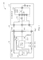
- FIG. 1 is a diagram of a system 100 according to a first embodiment of the invention.
- the system 100 comprises a battery 105, a portable device 110, and a specific connecting interface 115.
- the specific connecting interface 115 is used for connecting between the battery 105 and the portable device 110.
- the specific connecting interface 115 may be implemented by using the MIPI battery interface (MIPI BIF).
- MIPI BIF MIPI battery interface
- the portable device 110 and the battery 105 can communicate with each other via the specific connecting interface 115.
- the specific connecting interface 115 comprises a supply line VBAT, a battery communication line BCL, and a ground line GND.
- a user can press a power key at the side of the portable device 110 to deactivate or release a shipping mode of the battery 105 via the battery communication line BCL; however, this is not meant to be a limitation of the invention.
- the user may press the power key to deactivate or release the shipping mode of the battery 105 via the supply line VBAT.
- the user from the portable device 110 may activate or enable the shipping mode of battery 105 via the battery communication line BCL or the supply line VBAT. That is, the user can activate or deactivate (i. e. release) the shipping mode of battery 105 via signal transmission of the specific connecting interface 115.
- the shipping mode When the shipping mode is enabled or activated, this may mean that the system 100 is to be transferred from another place or country by ocean shipping or sea shipping for several days, and enabling the shipping mode can effectively save more power of battery 105 during this time period and will make the portable device 110 immediately reply to the user's control if needed. Enabling the shipping mode is also suitable for a condition that the user merely would not like to operate the portable device 110 for several days.
- the battery 105 comprises a battery cell 1051 and an internal circuit 1052.
- the internal circuit 1052 comprises a control circuit 1053 and a charging/discharging path that includes four switching units SW1 - SW4.
- the portable device 110 comprises a transmitting circuit 1101 and a control circuit 1102.
- the transmitting circuit 1101 comprises a resistor R4, and the control circuit 1102 comprises a switch unit SW that can be regarded as a power key connected to a resistor R5 and a power source.
- the control circuit 1053 is used for controlling the two switching units SW1 and SW2 disposed on the charging/discharging path so as to charge or discharge the battery cell 1051.
- the control circuit 1053 can be also used for protecting the battery cell 1051.
- control circuit 1053 can be used for storing information of control data, battery percentage, aging factor(s), battery cycle, battery capacity, and so on.
- the control circuit 1102 of portable device 110 can read information of control data, battery percentage, aging factors, battery cycle, and battery capacity from the internal circuit 1052 at the side of battery 105 via the connecting interface 115.
- the control circuit 1103 can also write information from the portable device 110 into the internal circuit 1052 within the battery 105 via the connecting interface 115.
- the portable device 110 is arranged to change a voltage level at the battery communication line BCL from a first level to a second level so as to control the battery 105 to enter the shipping mode or to exit and release the shipping mode.
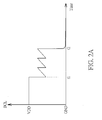
- FIG. 1 is a diagram illustrating a waveform of a signal level at the battery communication line BCL when the shipping mode is deactivated or released according to the embodiment of FIG. 1 .
- FIG. 2B is a diagram illustrating the waveform of the signal level at battery communication line BCL when the shipping mode is activated according to the embodiment of FIG. 1 .
- the control circuit 1053 controls the switch units SW1 and SW2 to be open, and the path from the battery cell 1051 to the level at the supply line VBAT becomes disconnected.
- the control circuit 1053 controls the switch unit SW3 to be closed and the switch unit SW4 to be open under the shipping mode.
- the voltage level at battery communication line BCL is almost equal to a logic high level such as a supply level VDD. Since the control circuit 1053 merely consumes a smaller current and almost all discharging paths for the battery cell 1051 are disconnected, power-off leakage currents become almost zero.
- the switch unit SW When a user enables the system 100 (or portable device 110) by pressing the power key at the side of portable device 110, the switch unit SW becomes closed, and the level at battery communication line BCL becomes lower.
- the control circuit 1053 at the side of battery 105 can detect the level at BCL by performing shipping mode detection to know whether the user presses the power key. In this situation, to deactivate or release the shipping mode, the control circuit 1503 controls the switch unit SW3 to be open and the switch unit SW4 to be closed. Accordingly, the level at BCL is discharged via a resistor to the ground level GND and becomes lower.
- the vertical axis indicates the level at BCL
- the horizontal axis indicates different timings.
- the system 100 Before timing t1, the system 100 is operating under the shipping mode, and the level at BCL is kept at a high level (e.g. a first level). From timing t1 to timing t2, the system 100 performs shipping mode detection and detects that the level at BCL becomes lower (e.g. a second level) due to that the user presses the power key. Accordingly the control circuit 1503 is arranged to control the switch unit SW3 to be open and the switch unit SW4 to be closed. After timing t2, the system 100 (or battery 105) has released/exited the shipping mode.
- a high level e.g. a first level
- the system 100 may enter the shipping mode.
- the portable device 110 can change the voltage level at the battery communication line BCL from a first level to a second level so as to control the battery 105 to enter the shipping mode.
- FIG. 2B it is assumed that the system 100 (or battery 105) operates under a normal mode before timing t3.
- the control circuit 1102 can send a shipping mode enable signal to the control circuit 1053 via the battery communication line BCL of the connecting interface 115, and this shipping mode enable signal makes a change for the voltage level at battery communication line BCL.
- the control circuit 1053 controls the switch units SW1 and SW2 to be open so that the discharging path from battery cell 1051 to ground level GND can be disconnected.
- the control circuit 1053 controls the switch unit SW3 to be closed and the switch unit SW4 to be open so that the voltage level of BCL can be kept at a higher level such as VDD.
- the control circuit 1053 can delay several seconds and then enter the shipping mode after receiving the shipping mode enable signal during t3 - t4 via the battery communication line BCL of connecting interface 115.
- a portable device can be arranged to control a battery to enter and/or exit the shipping mode by different signal transmission via the battery communication line BCL of a specific connecting interface.
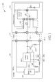
- FIG. 3 is a diagram of a system 300 according to a second embodiment of the invention.
- the system 300 comprises a battery 305 and a portable device 310.
- a specific connecting interface 315 is employed and used for connecting between the battery 305 and the portable device 310.
- the specific connecting interface 315 may be implemented by using the interface of MIPI BIF standard.
- the portable device 310 and the battery 305 can communicate with each other via the specific connecting interface 315.
- the specific connecting interface 315 comprises a supply line VBAT, a battery communication line BCL, and a ground line GND.
- a user can press a power key at the side of the portable device 310 to deactivate a shipping mode of the battery 305 via the battery communication line BCL; however, this is not meant to be a limitation of the invention.
- the user from the portable device 310 may activate the shipping mode of battery 305 via the battery communication line BCL. That is, the user can activate or deactivate (i.e. release) the shipping mode of battery 305 via signal transmission of the specific connecting interface 315.
- the shipping mode When the shipping mode is enabled or activated, this may mean that the system 300 is to be transferred from another place or country by ocean shipping or sea shipping for several days, and enabling the shipping mode can effectively save more power of battery 305 and makes the portable device 310 immediately reply to the user's control if needed. Enabling the shipping mode is also suitable for a condition that the user merely would not like to operate the portable device 310 for several days.
- the battery 305 comprises a battery cell 3051 and an internal circuit 3052.
- the internal circuit 3052 comprises a control circuit 3053 and a charging/discharging path that includes four switch units SW1 - SW2 and SW5 - SW6.
- the portable device 310 comprises a transmitting circuit 3101 and a control circuit 3102.
- the transmitting circuit 3101 comprises a resistor R4, and the control circuit 3102 comprises a switch unit SW that can be regarded as a power key connected to a resistor R5.
- the control circuit 3053 is used for controlling the two switch units SW1 and SW2 disposed on the charging/discharging path to charge or discharge the battery cell 3051.
- the control circuit 3053 can be also used for protecting the battery cell 3051.
- control circuit 3053 can be used for storing information of control data, battery percentage, aging factor(s), battery cycle, battery capacity, and so on.
- the control circuit 3102 of portable device 310 can read information of control data, battery percentage, aging factors, battery cycle, and battery capacity from the internal circuit 3052 at the side of battery pack 305 via the connecting interface 315.
- the control circuit 3102 can also write information from the portable device 310 into the internal circuit 3052 within the battery 305 via the connecting interface 315.
- FIG. 4A is a diagram illustrating a waveform of BCL when the shipping mode is deactivated or released according to the embodiment of FIG. 3 .
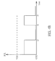
- FIG. 4B is a diagram illustrating the waveform of BCL when the shipping mode is activated according to the embodiment of FIG. 3 .
- the control circuit 3053 controls the switch units SW1 and SW2 to be closed.
- the control circuit 3053 controls the switch unit SW5 to be open and the switch unit SW6 to be closed under the shipping mode.
- the voltage level at BCL is almost equal to a logic low level GND. Since the control circuit 3053 merely consumes a smaller current and almost all discharging paths for the battery cell 1051 are disconnected, power-off leakage currents become almost zero.
- the switch unit SW When a user enables the system 300 by pressing the power key at the side of portable device 310, the switch unit SW becomes closed, and the level at BCL will become higher since the portable device 310 is arranged to charge the level at BCL via the resistor R5 and the switch unit SW based on the supply voltage at VBAT.
- the control circuit 3053 at the side of battery 305 can detect the level at BCL by performing shipping mode detection to know whether the user presses the power key. In this situation, to deactivate or release the shipping mode, the control circuit 3503 controls the switch unit SW5 to be closed and the switch unit SW6 to be open. Accordingly, the level at BCL is charged by the portable device 310 from the ground level GND to a higher level. As shown in FIG.
- the vertical axis indicates the level at BCL
- the horizontal axis indicates different timings.
- the system 300 Before timing t1, the system 300 is operating under the shipping mode. From timing t1 to timing t2, the system 300 performs shipping mode detection and detects that the level at BCL becomes higher due to that the user presses the power key. Accordingly the control circuit 3503 is arranged to control the switch unit SW5 to be closed and the switch unit SW6 to be open. After timing t2, the system 100 (or battery 105) has released/exited the shipping mode, and the level at BCL can be discharged so as to save more power.
- the system 300 may enter the shipping mode. As shown in FIG. 4B , it is assumed that the system 300 (or battery 305) operates under a normal mode before timing t3, and the level at BCL is kept at a higher level.
- the control circuit 3102 can send a shipping mode enable signal to the control circuit 3053 via the battery communication line BCL of the connecting interface 315.
- the control circuit 3053 controls the switch units SW1 and SW2 to be closed.
- the control circuit 3053 controls the switch unit SW5 to be open and the switch unit SW6 to be closed so that the voltage level of BCL will become a lower level.
- control circuit 3053 can delay several seconds (from timing t4 to timing t5) and then make the battery 305 enter the shipping mode after receiving the shipping mode enable signal during t3 - t4 via the battery communication line BCL of connecting interface 115.
- a portable device may control a battery to enter the shipping mode or exit the shipping mode according to a change of a voltage level at the supply line VBAT of a specific connecting interface and/or a signal transmission of the supply line VBAT of a specific connecting interface.
- FIG. 5 is a diagram of a system 500 according to a third embodiment of the invention.
- the system 500 comprises a battery 505, a portable device 510, and a connecting interface 515 used for connecting between the battery 505 and portable device 510.
- the portable device 510 comprises a control circuit 5102 and a charger circuit 5103 that includes a switch unit SW7.
- the switch unit SW7 is configured for selectively enabling/disabling the power path of the supply line VBAT connecting between the battery 505 and portable device 510, so that the voltage level at the supply line VBAT will be changed.
- the control circuit 5102 controls the switch unit SW7 of the charger circuit 5103 to be open. That is, the charger circuit 5103 is disabled under the shipping mode, and the power path is disconnected. Accordingly the portable device 510 would not consume too many currents from the battery 505. The portable device 505 becomes almost disabled, and power-off leaking currents are small.
- the portable device 510 is enabled and then used to enable the charger circuit 5103.
- the switch unit SW7 becomes closed, and the battery 505 can be arranged for providing power for the portable device 510 via the connecting interface 515. That is, by dynamically establishing or disconnecting a power path from the battery 505 to the portable device 510 via the connecting interface 515, the portable device 515 can control the battery 505 to enter the shipping mode or exit the shipping mode by equivalently changing the voltage level at the supply line VBAT from a high level to a low level.
- the charger circuit 5103 may be optional. This is illustrated in FIG. 6 , which is a diagram of a system 600 according to a fourth embodiment of the invention. Further description of the operations is not detailed for brevity.
- a portable device can make a battery enter or exit the shipping mode via a connecting interface.
- this may be implemented by using the supply line VBAT or the battery communication line BCL included within the connecting interface.
- BCL or VBAT battery communication line
- it is not necessary to employ an additional signal port to enable/disable the shipping mode. Circuit costs can be effectively reduced.
- the example of one-wire communication (BCL or VBAT) to activate/deactivate the shipping mode via the connecting interface is not meant to be a limitation of the invention. In other examples, two-wire communication to activate/deactivate the shipping mode via the connecting interface may be employed.
Landscapes
- Engineering & Computer Science (AREA)
- Power Engineering (AREA)
- Charge And Discharge Circuits For Batteries Or The Like (AREA)
- Telephone Function (AREA)
- Secondary Cells (AREA)
Abstract
Description
- The present invention relates to a method, a system, and a battery according to the pre-characterizing clauses of claims 1, 6, and 11.
- Generally speaking, a portable device including a battery may be transferred from another place or country by ocean shipping or sea shipping for several days after leaving factory to the market. In this situation, even though the portable device is powered off, internal circuits within the portable device still consume power-off leakage currents from the battery. Accordingly, the remaining capacity of the battery may be not enough for a user to enable the system on the portable device if the power-off leakage currents become higher. It is important to provide a novel scheme to solve this problem.
- This in mind, the present invention aims at providing a method for controlling a state of a battery to enter a shipping mode and exit the shipping mode by using a specific connecting interface and related system and battery thereof.
- This is achieved by a method according to claim 1, a system according to claim 6, and a battery according to claim 11. The respective dependent claims pertain to corresponding further development and improvements.
- As will be seen more clearly from the detailed description following below, a claimed method for controlling a state of a battery includes: providing and using a specific connecting interface to connect the battery and a portable device; and controlling the battery to enter a shipping mode and exit the shipping mode by using the specific connecting interface
- Additionally, a claimed system includes a portable device, a battery, and a specific connecting interface. The battery is coupled to the portable device and configured to provide power for the system operating on the portable device. The specific connecting interface is configured to connect between the portable device and the battery. The portable device is arranged to control the battery to enter a shipping mode and exit the shipping mode by using the specific connecting interface.
- Additionally, a claimed battery connected to a portable device via a specific connecting interface includes a battery cell and a control circuit. The control circuit is coupled to the battery cell and the specific connecting interface, and is configured to detect a signal of the specific connecting interface and to determine entering a shipping mode and exiting the shipping mode according to the signal of the specific connecting interface.
- In the following, the invention is further illustrated by way of example, taking reference to the accompanying drawings. Thereof
-
FIG. 1 is a diagram of a system according to a first embodiment of the invention. -
FIG. 2A is a diagram illustrating a waveform of BCL when the shipping mode is deactivated or released according to the embodiment ofFIG. 1 . -
FIG. 2B is a diagram illustrating the waveform of BCL when the shipping mode is activated according to the embodiment ofFIG. 1 . -
FIG. 3 is a diagram of a system according to a second embodiment of the invention. -
FIG. 4A is a diagram illustrating a waveform of BCL when the shipping mode is deactivated or released according to the embodiment ofFIG. 3 . -
FIG. 4B is a diagram illustrating the waveform of BCL when the shipping mode is activated according to the embodiment ofFIG. 3 . -
FIG. 5 is a diagram of a system according to a third embodiment of the invention. -
FIG. 6 is a diagram of a system according to a fourth embodiment of the invention. - Please refer to
FIG. 1 , which is a diagram of asystem 100 according to a first embodiment of the invention. Thesystem 100 comprises abattery 105, aportable device 110, and aspecific connecting interface 115. Thespecific connecting interface 115 is used for connecting between thebattery 105 and theportable device 110. For example, thespecific connecting interface 115 may be implemented by using the MIPI battery interface (MIPI BIF). Theportable device 110 and thebattery 105 can communicate with each other via thespecific connecting interface 115. Thespecific connecting interface 115 comprises a supply line VBAT, a battery communication line BCL, and a ground line GND. In this embodiment, a user can press a power key at the side of theportable device 110 to deactivate or release a shipping mode of thebattery 105 via the battery communication line BCL; however, this is not meant to be a limitation of the invention. In another embodiment, the user may press the power key to deactivate or release the shipping mode of thebattery 105 via the supply line VBAT. In addition, the user from theportable device 110 may activate or enable the shipping mode ofbattery 105 via the battery communication line BCL or the supply line VBAT. That is, the user can activate or deactivate (i. e. release) the shipping mode ofbattery 105 via signal transmission of thespecific connecting interface 115. When the shipping mode is enabled or activated, this may mean that thesystem 100 is to be transferred from another place or country by ocean shipping or sea shipping for several days, and enabling the shipping mode can effectively save more power ofbattery 105 during this time period and will make theportable device 110 immediately reply to the user's control if needed. Enabling the shipping mode is also suitable for a condition that the user merely would not like to operate theportable device 110 for several days. - In practice, the
battery 105 comprises abattery cell 1051 and aninternal circuit 1052. Theinternal circuit 1052 comprises acontrol circuit 1053 and a charging/discharging path that includes four switching units SW1 - SW4. Theportable device 110 comprises atransmitting circuit 1101 and acontrol circuit 1102. Thetransmitting circuit 1101 comprises a resistor R4, and thecontrol circuit 1102 comprises a switch unit SW that can be regarded as a power key connected to a resistor R5 and a power source. Thecontrol circuit 1053 is used for controlling the two switching units SW1 and SW2 disposed on the charging/discharging path so as to charge or discharge thebattery cell 1051. Thecontrol circuit 1053 can be also used for protecting thebattery cell 1051. In addition, thecontrol circuit 1053 can be used for storing information of control data, battery percentage, aging factor(s), battery cycle, battery capacity, and so on. Thecontrol circuit 1102 ofportable device 110 can read information of control data, battery percentage, aging factors, battery cycle, and battery capacity from theinternal circuit 1052 at the side ofbattery 105 via the connectinginterface 115. In addition, the control circuit 1103 can also write information from theportable device 110 into theinternal circuit 1052 within thebattery 105 via the connectinginterface 115. - For the operation of shipping mode, the
portable device 110 is arranged to change a voltage level at the battery communication line BCL from a first level to a second level so as to control thebattery 105 to enter the shipping mode or to exit and release the shipping mode. Please refer toFIG. 1 in conjunction withFIG. 2A andFIG. 2B .FIG. 2A is a diagram illustrating a waveform of a signal level at the battery communication line BCL when the shipping mode is deactivated or released according to the embodiment ofFIG. 1 .FIG. 2B is a diagram illustrating the waveform of the signal level at battery communication line BCL when the shipping mode is activated according to the embodiment ofFIG. 1 . When the system 100 (or the battery 105) enters the shipping mode, thecontrol circuit 1053 controls the switch units SW1 and SW2 to be open, and the path from thebattery cell 1051 to the level at the supply line VBAT becomes disconnected. In addition, thecontrol circuit 1053 controls the switch unit SW3 to be closed and the switch unit SW4 to be open under the shipping mode. Thus, under the shipping mode, the voltage level at battery communication line BCL is almost equal to a logic high level such as a supply level VDD. Since thecontrol circuit 1053 merely consumes a smaller current and almost all discharging paths for thebattery cell 1051 are disconnected, power-off leakage currents become almost zero. - When a user enables the system 100 (or portable device 110) by pressing the power key at the side of
portable device 110, the switch unit SW becomes closed, and the level at battery communication line BCL becomes lower. Via the connectinginterface 115, thecontrol circuit 1053 at the side ofbattery 105 can detect the level at BCL by performing shipping mode detection to know whether the user presses the power key. In this situation, to deactivate or release the shipping mode, the control circuit 1503 controls the switch unit SW3 to be open and the switch unit SW4 to be closed. Accordingly, the level at BCL is discharged via a resistor to the ground level GND and becomes lower. As shown inFIG. 2A , the vertical axis indicates the level at BCL, and the horizontal axis indicates different timings. Before timing t1, thesystem 100 is operating under the shipping mode, and the level at BCL is kept at a high level (e.g. a first level). From timing t1 to timing t2, thesystem 100 performs shipping mode detection and detects that the level at BCL becomes lower (e.g. a second level) due to that the user presses the power key. Accordingly the control circuit 1503 is arranged to control the switch unit SW3 to be open and the switch unit SW4 to be closed. After timing t2, the system 100 (or battery 105) has released/exited the shipping mode. - The system 100 (or battery 105) may enter the shipping mode. The
portable device 110 can change the voltage level at the battery communication line BCL from a first level to a second level so as to control thebattery 105 to enter the shipping mode. As shown inFIG. 2B , it is assumed that the system 100 (or battery 105) operates under a normal mode before timing t3. To enter the shipping mode, from timing t3 to timing t4, thecontrol circuit 1102 can send a shipping mode enable signal to thecontrol circuit 1053 via the battery communication line BCL of the connectinginterface 115, and this shipping mode enable signal makes a change for the voltage level at battery communication line BCL. After receiving the shipping mode enable signal, thecontrol circuit 1053 controls the switch units SW1 and SW2 to be open so that the discharging path frombattery cell 1051 to ground level GND can be disconnected. In addition, thecontrol circuit 1053 controls the switch unit SW3 to be closed and the switch unit SW4 to be open so that the voltage level of BCL can be kept at a higher level such as VDD. As shown in 2B, thecontrol circuit 1053 can delay several seconds and then enter the shipping mode after receiving the shipping mode enable signal during t3 - t4 via the battery communication line BCL of connectinginterface 115. - Additionally, in other embodiments, a portable device can be arranged to control a battery to enter and/or exit the shipping mode by different signal transmission via the battery communication line BCL of a specific connecting interface. Please refer to
FIG. 3 , which is a diagram of asystem 300 according to a second embodiment of the invention. Thesystem 300 comprises abattery 305 and aportable device 310. A specific connectinginterface 315 is employed and used for connecting between thebattery 305 and theportable device 310. For example, the specific connectinginterface 315 may be implemented by using the interface of MIPI BIF standard. Theportable device 310 and thebattery 305 can communicate with each other via the specific connectinginterface 315. The specific connectinginterface 315 comprises a supply line VBAT, a battery communication line BCL, and a ground line GND. In this embodiment a user can press a power key at the side of theportable device 310 to deactivate a shipping mode of thebattery 305 via the battery communication line BCL; however, this is not meant to be a limitation of the invention. In addition, the user from theportable device 310 may activate the shipping mode ofbattery 305 via the battery communication line BCL. That is, the user can activate or deactivate (i.e. release) the shipping mode ofbattery 305 via signal transmission of the specific connectinginterface 315. When the shipping mode is enabled or activated, this may mean that thesystem 300 is to be transferred from another place or country by ocean shipping or sea shipping for several days, and enabling the shipping mode can effectively save more power ofbattery 305 and makes theportable device 310 immediately reply to the user's control if needed. Enabling the shipping mode is also suitable for a condition that the user merely would not like to operate theportable device 310 for several days. - In practice, the
battery 305 comprises abattery cell 3051 and aninternal circuit 3052. Theinternal circuit 3052 comprises acontrol circuit 3053 and a charging/discharging path that includes four switch units SW1 - SW2 and SW5 - SW6. Theportable device 310 comprises atransmitting circuit 3101 and acontrol circuit 3102. The transmittingcircuit 3101 comprises a resistor R4, and thecontrol circuit 3102 comprises a switch unit SW that can be regarded as a power key connected to a resistor R5. Thecontrol circuit 3053 is used for controlling the two switch units SW1 and SW2 disposed on the charging/discharging path to charge or discharge thebattery cell 3051. Thecontrol circuit 3053 can be also used for protecting thebattery cell 3051. In addition, thecontrol circuit 3053 can be used for storing information of control data, battery percentage, aging factor(s), battery cycle, battery capacity, and so on. Thecontrol circuit 3102 ofportable device 310 can read information of control data, battery percentage, aging factors, battery cycle, and battery capacity from theinternal circuit 3052 at the side ofbattery pack 305 via the connectinginterface 315. In addition, thecontrol circuit 3102 can also write information from theportable device 310 into theinternal circuit 3052 within thebattery 305 via the connectinginterface 315. - For the operation of shipping mode, please refer to
FIG. 3 in conjunction withFIG. 4A andFIG. 4B .FIG. 4A is a diagram illustrating a waveform of BCL when the shipping mode is deactivated or released according to the embodiment ofFIG. 3 .FIG. 4B is a diagram illustrating the waveform of BCL when the shipping mode is activated according to the embodiment ofFIG. 3 . When the system 300 (or the battery 305) enters the shipping mode, thecontrol circuit 3053 controls the switch units SW1 and SW2 to be closed. In addition, thecontrol circuit 3053 controls the switch unit SW5 to be open and the switch unit SW6 to be closed under the shipping mode. Thus, under the shipping mode, the voltage level at BCL is almost equal to a logic low level GND. Since thecontrol circuit 3053 merely consumes a smaller current and almost all discharging paths for thebattery cell 1051 are disconnected, power-off leakage currents become almost zero. - When a user enables the
system 300 by pressing the power key at the side ofportable device 310, the switch unit SW becomes closed, and the level at BCL will become higher since theportable device 310 is arranged to charge the level at BCL via the resistor R5 and the switch unit SW based on the supply voltage at VBAT. Via the connectinginterface 315, thecontrol circuit 3053 at the side ofbattery 305 can detect the level at BCL by performing shipping mode detection to know whether the user presses the power key. In this situation, to deactivate or release the shipping mode, the control circuit 3503 controls the switch unit SW5 to be closed and the switch unit SW6 to be open. Accordingly, the level at BCL is charged by theportable device 310 from the ground level GND to a higher level. As shown inFIG. 4A , the vertical axis indicates the level at BCL, and the horizontal axis indicates different timings. Before timing t1, thesystem 300 is operating under the shipping mode. From timing t1 to timing t2, thesystem 300 performs shipping mode detection and detects that the level at BCL becomes higher due to that the user presses the power key. Accordingly the control circuit 3503 is arranged to control the switch unit SW5 to be closed and the switch unit SW6 to be open. After timing t2, the system 100 (or battery 105) has released/exited the shipping mode, and the level at BCL can be discharged so as to save more power. - The system 300 (or battery 305) may enter the shipping mode. As shown in
FIG. 4B , it is assumed that the system 300 (or battery 305) operates under a normal mode before timing t3, and the level at BCL is kept at a higher level. To enter the shipping mode, from timing t3 to timing t4, thecontrol circuit 3102 can send a shipping mode enable signal to thecontrol circuit 3053 via the battery communication line BCL of the connectinginterface 315. After receiving the shipping mode enable signal, thecontrol circuit 3053 controls the switch units SW1 and SW2 to be closed. In addition, thecontrol circuit 3053 controls the switch unit SW5 to be open and the switch unit SW6 to be closed so that the voltage level of BCL will become a lower level. As shown in 4B, thecontrol circuit 3053 can delay several seconds (from timing t4 to timing t5) and then make thebattery 305 enter the shipping mode after receiving the shipping mode enable signal during t3 - t4 via the battery communication line BCL of connectinginterface 115. - Further, in other embodiments, a portable device may control a battery to enter the shipping mode or exit the shipping mode according to a change of a voltage level at the supply line VBAT of a specific connecting interface and/or a signal transmission of the supply line VBAT of a specific connecting interface. Please refer to
FIG. 5 , which is a diagram of asystem 500 according to a third embodiment of the invention. As shown inFIG. 5 , thesystem 500 comprises abattery 505, aportable device 510, and a connectinginterface 515 used for connecting between thebattery 505 andportable device 510. Theportable device 510 comprises acontrol circuit 5102 and acharger circuit 5103 that includes a switch unit SW7. The switch unit SW7 is configured for selectively enabling/disabling the power path of the supply line VBAT connecting between thebattery 505 andportable device 510, so that the voltage level at the supply line VBAT will be changed. When the system 500 (or the battery 505) operates under the shipping mode, thecontrol circuit 5102 controls the switch unit SW7 of thecharger circuit 5103 to be open. That is, thecharger circuit 5103 is disabled under the shipping mode, and the power path is disconnected. Accordingly theportable device 510 would not consume too many currents from thebattery 505. Theportable device 505 becomes almost disabled, and power-off leaking currents are small. When a user presses the power key to enable thesystem 500, theportable device 510 is enabled and then used to enable thecharger circuit 5103. Accordingly, the switch unit SW7 becomes closed, and thebattery 505 can be arranged for providing power for theportable device 510 via the connectinginterface 515. That is, by dynamically establishing or disconnecting a power path from thebattery 505 to theportable device 510 via the connectinginterface 515, theportable device 515 can control thebattery 505 to enter the shipping mode or exit the shipping mode by equivalently changing the voltage level at the supply line VBAT from a high level to a low level. Furthermore, in other embodiments, thecharger circuit 5103 may be optional. This is illustrated inFIG. 6 , which is a diagram of asystem 600 according to a fourth embodiment of the invention. Further description of the operations is not detailed for brevity. - In summary, in the embodiments of the invention, a portable device can make a battery enter or exit the shipping mode via a connecting interface. In practice, this may be implemented by using the supply line VBAT or the battery communication line BCL included within the connecting interface. Thus, it is not necessary to employ an additional signal port to enable/disable the shipping mode. Circuit costs can be effectively reduced. Further, it should be noted that the example of one-wire communication (BCL or VBAT) to activate/deactivate the shipping mode via the connecting interface is not meant to be a limitation of the invention. In other examples, two-wire communication to activate/deactivate the shipping mode via the connecting interface may be employed.
Claims (16)
- A method for controlling a state of a battery (105, 305, 505), characterized by:providing and using a specific connecting interface (115, 315, 515) to connect the battery (105, 305, 505) and a portable device (110, 310, 510, 610); andcontrolling the battery (105, 305, 505) to enter a shipping mode and exit the shipping mode by using the specific connecting interface (115, 315, 515).
- The method of claim 1, characterized in that the specific connecting interface (115, 315, 515) comprises a supply line, and the step of controlling the battery (105, 305, 505) to enter the shipping mode and exit the shipping mode comprises:controlling the battery (105, 305, 505) to enter the shipping mode and exit the shipping mode according to change of a voltage level at the supply line.
- The method of claim 2, characterized in that the step of controlling the battery (105, 305, 505) to enter the shipping mode and exit the shipping mode according to the change of the voltage level at the supply line comprises:providing and using a switch unit to selectively enable/disable a power path of the supply line connecting between the battery (105, 305, 505) and the portable device (110, 310, 510, 610) so as to change the voltage level at the supply line; andcontrolling the battery (105, 305, 505) to enter the shipping mode and exit the shipping mode according to the change of the voltage level at the supply line.
- The method of claim 2, characterized in that the step of controlling the battery (105, 305, 505) to enter the shipping mode and exit the shipping mode according to the change of the voltage level at the supply line comprises:controlling the battery (105, 305, 505) to enter the shipping mode by changing the voltage level at the supply line from a high level to a low level; andcontrolling the battery (105, 305, 505) to exit the shipping mode when detecting the voltage level at the supply line has been changed by an external power key.
- The method of claim 1, characterized in that the specific connecting interface (115, 315, 515) comprises a battery communication line, and the step of controlling the battery (105, 305, 505) to enter the shipping mode and exit the shipping mode comprises:changing a voltage level at the battery communication line from a first level to a second level so as to control the battery (105, 305, 505) to enter the shipping mode; andchanging the voltage level at the battery communication line from the second level to the first level so as to control the battery (105, 305, 505) to exit and release the shipping mode.
- A system (100, 300, 500, 600), comprising:a portable device (110, 310, 510, 610);a battery (105, 305, 505), coupled to the portable device (110, 310, 510, 610), configured to provide power for the system 100, 300, 500, 600) operating on the portable device (110, 310, 510, 610); andcharacterized by:a specific connecting interface (115, 315, 515), configured to connect between the portable device (110, 310, 510, 610) and the battery (105, 305, 505);wherein the portable device (110, 310, 510, 610) is arranged to control the battery (105, 305, 505) to enter a shipping mode and exit the shipping mode by using the specific connecting interface (115, 315, 515).
- The system (100, 300, 500, 600) of claim 6, characterized in that the specific connecting interface (115, 315, 515) comprises a supply line, and the portable device (110, 310, 510, 610) controls the battery (105, 305, 505) to enter the shipping mode and exit the shipping mode according to change of a voltage level at the supply line.
- The system (100, 300, 500, 600) of claim 7, characterized in that the system (100, 300, 500, 600) further comprises:a switch unit, connected between the specific connecting interface (115, 315, 515) and the battery (105, 305, 505), configured to selectively enable/disable a power path of the supply line connecting between the battery (105, 305, 505) and the portable device (110, 310, 510, 610) so as to change the voltage level at the supply line;wherein the portable device (110, 310, 510, 610) controls the battery (105, 305, 505) to enter the shipping mode and exit the shipping mode according to the change of the voltage level at the supply line.
- The system (100, 300, 500, 600) of claim 7, characterized in that the portable device (110, 310, 510, 610) controls the battery (105, 305, 505) to enter the shipping mode by changing the voltage level at the supply line from a high level to a low level; and the portable device (110, 310, 510, 610) controls the battery (105, 305, 505) to exit the shipping mode when detecting the voltage level at the supply line has been changed by an external power key.
- The system (100, 300, 500, 600) of claim 6, characterized in that the specific connecting interface (115, 315, 515) comprises a battery communication line, and the portable device (110, 310, 510, 610) changes a voltage level at the battery communication line from a first level to a second level so as to control the battery (105, 305, 505) to enter the shipping mode, and the portable device (110, 310, 510, 610) changes the voltage level at the battery communication line from the second level to the first level so as to control the battery (105, 305, 505) to exit and release the shipping mode.
- A battery (105, 305, 505) connected to a portable device (110, 310, 510, 610) via a specific connecting interface (115, 315, 515), comprising:a battery cell (1051, 3051, 5051); andcharacterized by:a control circuit (1053, 3053, 5053), coupled to the battery cell (1051, 3051, 5051) and the specific connecting interface (115, 315, 515), configured to detect a signal of the specific connecting interface (115, 315, 515) and to determine entering a shipping mode and exiting the shipping mode according to the signal of the specific connecting interface (115, 315, 515).
- The battery (105, 305, 505) of claim 11, characterized in that the specific connecting interface (115, 315, 515) comprises a supply line, and the control circuit (1053, 3053, 5053) is arranged to determine entering the shipping mode and exiting the shipping mode according to change of a voltage level at the supply line.
- The battery (105, 305, 505) of claim 12, characterized in that the control circuit (1053, 3053, 5053) determines entering the shipping mode when detecting that the voltage level at the supply line changes from a high level to a low level; and, the control circuit (1053, 3053, 5053) determines exiting the shipping mode when detecting that the voltage level at the supply line has been changed by an external power key.
- The battery (105, 305, 505) of claim 11, characterized in that the specific connecting interface (115, 315, 515) comprises a battery communication line, and the control circuit (1053, 3053, 5053) is arranged to determine entering the shipping mode when detecting that a voltage level at the battery communication line changes from a first level to a second level, and to determine exiting and releasing the shipping mode when detecting that the voltage level at the battery communication line changes from the second level to the first level.
- The battery (105, 305, 505) of claim 14, characterized in that the control circuit (1053, 3053, 5053) is arranged to make the voltage level at the battery communication line change from a high level to a low level, and to determine releasing the shipping mode when detecting that the voltage level has changed from the low level to the high level.
- The battery (105, 305, 505) of claim 14, characterized in that the control circuit (1053, 3053, 5053) is arranged to make the voltage level at the battery communication line change from a low level to a high level, and to determine releasing the shipping mode when detecting that the voltage level has changed from the high level to the low level.
Applications Claiming Priority (2)
| Application Number | Priority Date | Filing Date | Title |
|---|---|---|---|
| US201462037256P | 2014-08-14 | 2014-08-14 | |
| US14/822,877 US10211655B2 (en) | 2014-08-14 | 2015-08-10 | Scheme for activating or deactivating shipping mode for battery via battery connecting interface without additional signal port(s) |
Publications (2)
| Publication Number | Publication Date |
|---|---|
| EP2985855A1 true EP2985855A1 (en) | 2016-02-17 |
| EP2985855B1 EP2985855B1 (en) | 2019-02-27 |
Family
ID=54106111
Family Applications (1)
| Application Number | Title | Priority Date | Filing Date |
|---|---|---|---|
| EP15180908.4A Active EP2985855B1 (en) | 2014-08-14 | 2015-08-13 | Scheme for activating or deactivating shipping mode for battery via battery connecting interface without additional signal port(s) |
Country Status (3)
| Country | Link |
|---|---|
| US (1) | US10211655B2 (en) |
| EP (1) | EP2985855B1 (en) |
| CN (1) | CN105375549B (en) |
Cited By (3)
| Publication number | Priority date | Publication date | Assignee | Title |
|---|---|---|---|---|
| WO2018031079A1 (en) * | 2016-08-11 | 2018-02-15 | K2 Energy Solutions, Inc. | Battery system with shipping mode |
| AT17064U1 (en) * | 2019-05-27 | 2021-04-15 | Einhell Germany Ag | Switching several variables in transport mode |
| WO2022006697A1 (en) * | 2020-07-06 | 2022-01-13 | Harman International Industries, Incorporated | Deep sleep circuit design for tws |
Families Citing this family (28)
| Publication number | Priority date | Publication date | Assignee | Title |
|---|---|---|---|---|
| WO2017117730A1 (en) * | 2016-01-05 | 2017-07-13 | 广东欧珀移动通信有限公司 | Rapid charging method, mobile terminal and adapter |
| CN107294148A (en) * | 2016-04-01 | 2017-10-24 | 深圳市大疆创新科技有限公司 | Charge-discharge controller, method and battery component |
| WO2018112455A1 (en) | 2016-12-16 | 2018-06-21 | Milwaukee Electric Tool Corporation | Battery pack switch |
| AU2017375491B2 (en) | 2016-12-16 | 2021-06-10 | Milwaukee Electric Tool Corporation | Battery pack interface |
| WO2018175983A1 (en) * | 2017-03-24 | 2018-09-27 | Milwaukee Electric Tool Corporation | Terminal configuration for a battery pack |
| TWM578899U (en) | 2017-06-30 | 2019-06-01 | 美商米沃奇電子工具公司 | Electrical combination, power tool system, electric motor assembly, electric motor, battery pack and motor assembly |
| USD887980S1 (en) | 2018-02-16 | 2020-06-23 | Milwaukee Electric Tool Corporation | Interface portion of a battery pack |
| EP3833511B1 (en) | 2018-08-06 | 2023-06-07 | Techtronic Cordless GP | Systems and methods for selectively enabling the operation of a device |
| DE102018126045A1 (en) * | 2018-10-19 | 2020-04-23 | Vorwerk & Co. Interholding Gmbh | Electrical device, in particular household appliance |
| DE102018126042A1 (en) * | 2018-10-19 | 2020-04-23 | Vorwerk & Co. Interholding Gmbh | Electrical device, in particular household appliance |
| CN110262992B (en) * | 2019-06-24 | 2020-12-04 | 无锡睿勤科技有限公司 | a control device |
| CN110427017A (en) * | 2019-08-06 | 2019-11-08 | 宝能汽车有限公司 | Remote information processor and its power consumption management method, car networking system and automobile |
| CN111124041A (en) * | 2019-10-28 | 2020-05-08 | 出门问问信息科技有限公司 | Wearable device control device and method and wearable device |
| US11979041B2 (en) * | 2020-01-08 | 2024-05-07 | GLF INTEGRATED POWER INC., a Delaware corporation | Methods and apparatuses for ultra-portable battery system protection and energy saving |
| US11502520B2 (en) | 2020-02-24 | 2022-11-15 | Motorola Solutions, Inc. | Battery protection circuit with isolation device failure detection |
| US11387645B2 (en) | 2020-05-08 | 2022-07-12 | Motorola Solutions, Inc. | Apparatus and method for adaptive active current limit protection |
| US11264814B2 (en) | 2020-05-08 | 2022-03-01 | Motorola Solutions, Inc. | Method and apparatus for connecting a battery power source to a portable electronic device |
| WO2022042708A1 (en) * | 2020-08-27 | 2022-03-03 | 西安稳先半导体科技有限责任公司 | System-on-chip, battery assembly, electronic device, battery protection circuit, test subsystem, test system, bluetooth earphone, shipping mode setting method, and computer readable storage medium |
| CN111987772B (en) * | 2020-08-27 | 2022-05-20 | 西安稳先半导体科技有限责任公司 | On-chip system, battery pack and electronic device |
| CN112986738B (en) * | 2021-03-01 | 2022-04-15 | 西安稳先半导体科技有限责任公司 | Shipping mode setting method, electronic device, and computer-readable storage medium |
| KR20220127643A (en) * | 2021-03-11 | 2022-09-20 | 삼성전자주식회사 | Electronic device including battery pack, operating method in the electronic device |
| CN113178908A (en) * | 2021-04-21 | 2021-07-27 | 深圳市沛城电子科技有限公司 | Battery charging and discharging circuit and control method of battery pack |
| US12136840B2 (en) * | 2021-12-24 | 2024-11-05 | Motorola Solutions, Inc. | Device, battery and system to control battery power |
| USD1114724S1 (en) | 2022-03-08 | 2026-02-24 | Milwaukee Electric Tool Corporation | Battery pack |
| CN115343980B (en) * | 2022-07-15 | 2025-09-19 | 深圳市正浩创新科技股份有限公司 | Control method of equipment, energy storage equipment and storage medium |
| USD1118483S1 (en) | 2023-06-29 | 2026-03-17 | Milwaukee Electric Tool Corporation | Battery pack |
| USD1120861S1 (en) | 2023-07-12 | 2026-03-31 | Milwaukee Electric Tool Corporation | Battery pack |
| CN118381136A (en) * | 2024-04-01 | 2024-07-23 | 维沃移动通信有限公司 | Battery protection circuit and electronic equipment |
Citations (4)
| Publication number | Priority date | Publication date | Assignee | Title |
|---|---|---|---|---|
| US20110107120A1 (en) * | 2009-11-02 | 2011-05-05 | Sony Corporation | Information processing apparatus, power supply control method, program and power supply control system |
| US20140167700A1 (en) * | 2012-12-18 | 2014-06-19 | Simplo Technology Company, Ltd. | Power consumption reduction method for a stored battery |
| JP2014113001A (en) * | 2012-12-05 | 2014-06-19 | Sanyo Electric Co Ltd | Charger and method of charging battery |
| WO2014198231A1 (en) * | 2013-06-14 | 2014-12-18 | Mediatek Inc. | Method for reading, writing, or updating information for battery cell via connecting interface between portable device and battery pack including battery cell so as to obtain precise information |
Family Cites Families (13)
| Publication number | Priority date | Publication date | Assignee | Title |
|---|---|---|---|---|
| WO2005038952A2 (en) | 2003-10-14 | 2005-04-28 | Black & Decker Inc. | Protection methods, protection circuits and protective devices for secondary batteries, a power tool, charger and battery pack adapted to provide protection against fault conditions in the battery pack |
| US7656131B2 (en) | 2005-10-31 | 2010-02-02 | Black & Decker Inc. | Methods of charging battery packs for cordless power tool systems |
| KR20080109497A (en) | 2007-06-13 | 2008-12-17 | 삼성전자주식회사 | Computer system and its control method |
| CN101409456B (en) | 2008-08-04 | 2010-12-22 | 深圳市同洲电子股份有限公司 | Charger and charging method thereof |
| US8138722B2 (en) * | 2008-10-17 | 2012-03-20 | Dell Products L.P. | Activating an information handling system battery from a ship mode |
| US8154255B2 (en) * | 2009-01-30 | 2012-04-10 | Dell Products L.P. | Systems and methods for waking up a battery system |
| JP4966998B2 (en) | 2009-06-18 | 2012-07-04 | パナソニック株式会社 | Charge control circuit, battery pack, and charging system |
| CN101882701B (en) | 2010-06-25 | 2013-09-11 | 中兴通讯股份有限公司 | Charging method and system |
| DE112010005714T5 (en) | 2010-06-30 | 2013-04-25 | Hewlett-Packard Development Company, L.P. | Battery pack for an electronic device |
| KR101877564B1 (en) | 2011-11-30 | 2018-07-12 | 삼성에스디아이 주식회사 | Battery pack |
| US9362764B2 (en) * | 2012-01-23 | 2016-06-07 | Tsuga Engineering Llc | Portable rechargeable power supply |
| EP3136117B1 (en) * | 2012-05-24 | 2020-08-19 | HeartWare, Inc. | Low-power battery monitoring with safety system |
| CN102957193B (en) | 2012-11-19 | 2015-12-23 | 中兴通讯股份有限公司 | A kind of charging management method, device and system |
-
2015
- 2015-08-10 US US14/822,877 patent/US10211655B2/en active Active
- 2015-08-12 CN CN201510492914.9A patent/CN105375549B/en active Active
- 2015-08-13 EP EP15180908.4A patent/EP2985855B1/en active Active
Patent Citations (4)
| Publication number | Priority date | Publication date | Assignee | Title |
|---|---|---|---|---|
| US20110107120A1 (en) * | 2009-11-02 | 2011-05-05 | Sony Corporation | Information processing apparatus, power supply control method, program and power supply control system |
| JP2014113001A (en) * | 2012-12-05 | 2014-06-19 | Sanyo Electric Co Ltd | Charger and method of charging battery |
| US20140167700A1 (en) * | 2012-12-18 | 2014-06-19 | Simplo Technology Company, Ltd. | Power consumption reduction method for a stored battery |
| WO2014198231A1 (en) * | 2013-06-14 | 2014-12-18 | Mediatek Inc. | Method for reading, writing, or updating information for battery cell via connecting interface between portable device and battery pack including battery cell so as to obtain precise information |
Cited By (3)
| Publication number | Priority date | Publication date | Assignee | Title |
|---|---|---|---|---|
| WO2018031079A1 (en) * | 2016-08-11 | 2018-02-15 | K2 Energy Solutions, Inc. | Battery system with shipping mode |
| AT17064U1 (en) * | 2019-05-27 | 2021-04-15 | Einhell Germany Ag | Switching several variables in transport mode |
| WO2022006697A1 (en) * | 2020-07-06 | 2022-01-13 | Harman International Industries, Incorporated | Deep sleep circuit design for tws |
Also Published As
| Publication number | Publication date |
|---|---|
| US20160049815A1 (en) | 2016-02-18 |
| EP2985855B1 (en) | 2019-02-27 |
| US10211655B2 (en) | 2019-02-19 |
| CN105375549A (en) | 2016-03-02 |
| CN105375549B (en) | 2019-05-10 |
Similar Documents
| Publication | Publication Date | Title |
|---|---|---|
| EP2985855B1 (en) | Scheme for activating or deactivating shipping mode for battery via battery connecting interface without additional signal port(s) | |
| US10784722B2 (en) | BLUETOOTH headset, charging cabin and charging system thereof | |
| EP3008790B1 (en) | Method for reading, writing, or updating information for battery cell via connecting interface between portable device and battery pack including battery cell so as to obtain precise information | |
| US20190050037A1 (en) | Intelligent mobile power supply and method for usb data communication therewith | |
| CN201781310U (en) | Battery charge control circuit | |
| US9674598B2 (en) | Audio accessory communication with active noise cancellation | |
| KR101216145B1 (en) | Method and apparatus for charging for battery of portable terminal | |
| JP2011097772A (en) | Battery-state monitoring circuit and battery device | |
| US20130170086A1 (en) | Overvoltage protection circuit and portable electronic device comprising same | |
| JP2018535493A (en) | USB interface circuit and method for low power operation | |
| US7068013B2 (en) | Battery circuit with non-volitable memory and thermistor on a single line | |
| US9225178B2 (en) | Charging apparatus | |
| JP5437770B2 (en) | Battery state monitoring circuit and battery device | |
| KR102035682B1 (en) | APPARATUS FOR CONTROLLING SERIAL AND PARALLEL OPERATION OF BATTERY PACKk | |
| US11355946B2 (en) | Communication architecture between ear bud device and charging device based on fewer pins | |
| CN106706998A (en) | Terminal test system and terminal test method | |
| CN210491166U (en) | Wireless earphone power supply circuit and wireless earphone | |
| CN224138168U (en) | An external battery and an electronic device for identifying the external battery. | |
| US20040124712A1 (en) | Circuit for preventing unintentional power off of mobile terminal and method thereof | |
| CN115459374B (en) | Wireless earphone and circuit thereof, charging box and circuit thereof, and wireless earphone assembly | |
| KR101864021B1 (en) | Etc obu system for dsrc | |
| KR101175242B1 (en) | Apparatus for inner charging in mobile communication terminal | |
| CN119543466A (en) | Wireless charging module, wireless charging processing method, device and electronic equipment | |
| KR200399021Y1 (en) | Usb device for gsm terminal | |
| CN120103231A (en) | External device presence detection method and related device |
Legal Events
| Date | Code | Title | Description |
|---|---|---|---|
| PUAI | Public reference made under article 153(3) epc to a published international application that has entered the european phase |
Free format text: ORIGINAL CODE: 0009012 |
|
| AK | Designated contracting states |
Kind code of ref document: A1 Designated state(s): AL AT BE BG CH CY CZ DE DK EE ES FI FR GB GR HR HU IE IS IT LI LT LU LV MC MK MT NL NO PL PT RO RS SE SI SK SM TR |
|
| AX | Request for extension of the european patent |
Extension state: BA ME |
|
| 17P | Request for examination filed |
Effective date: 20160318 |
|
| RBV | Designated contracting states (corrected) |
Designated state(s): AL AT BE BG CH CY CZ DE DK EE ES FI FR GB GR HR HU IE IS IT LI LT LU LV MC MK MT NL NO PL PT RO RS SE SI SK SM TR |
|
| GRAP | Despatch of communication of intention to grant a patent |
Free format text: ORIGINAL CODE: EPIDOSNIGR1 |
|
| STAA | Information on the status of an ep patent application or granted ep patent |
Free format text: STATUS: GRANT OF PATENT IS INTENDED |
|
| INTG | Intention to grant announced |
Effective date: 20181102 |
|
| GRAS | Grant fee paid |
Free format text: ORIGINAL CODE: EPIDOSNIGR3 |
|
| GRAJ | Information related to disapproval of communication of intention to grant by the applicant or resumption of examination proceedings by the epo deleted |
Free format text: ORIGINAL CODE: EPIDOSDIGR1 |
|
| GRAL | Information related to payment of fee for publishing/printing deleted |
Free format text: ORIGINAL CODE: EPIDOSDIGR3 |
|
| STAA | Information on the status of an ep patent application or granted ep patent |
Free format text: STATUS: REQUEST FOR EXAMINATION WAS MADE |
|
| GRAR | Information related to intention to grant a patent recorded |
Free format text: ORIGINAL CODE: EPIDOSNIGR71 |
|
| STAA | Information on the status of an ep patent application or granted ep patent |
Free format text: STATUS: GRANT OF PATENT IS INTENDED |
|
| GRAA | (expected) grant |
Free format text: ORIGINAL CODE: 0009210 |
|
| STAA | Information on the status of an ep patent application or granted ep patent |
Free format text: STATUS: THE PATENT HAS BEEN GRANTED |
|
| INTC | Intention to grant announced (deleted) | ||
| INTG | Intention to grant announced |
Effective date: 20190117 |
|
| AK | Designated contracting states |
Kind code of ref document: B1 Designated state(s): AL AT BE BG CH CY CZ DE DK EE ES FI FR GB GR HR HU IE IS IT LI LT LU LV MC MK MT NL NO PL PT RO RS SE SI SK SM TR |
|
| REG | Reference to a national code |
Ref country code: GB Ref legal event code: FG4D |
|
| REG | Reference to a national code |
Ref country code: CH Ref legal event code: EP |
|
| REG | Reference to a national code |
Ref country code: AT Ref legal event code: REF Ref document number: 1102724 Country of ref document: AT Kind code of ref document: T Effective date: 20190315 |
|
| REG | Reference to a national code |
Ref country code: IE Ref legal event code: FG4D |
|
| REG | Reference to a national code |
Ref country code: DE Ref legal event code: R096 Ref document number: 602015025243 Country of ref document: DE |
|
| REG | Reference to a national code |
Ref country code: NL Ref legal event code: MP Effective date: 20190227 |
|
| REG | Reference to a national code |
Ref country code: LT Ref legal event code: MG4D |
|
| PG25 | Lapsed in a contracting state [announced via postgrant information from national office to epo] |
Ref country code: SE Free format text: LAPSE BECAUSE OF FAILURE TO SUBMIT A TRANSLATION OF THE DESCRIPTION OR TO PAY THE FEE WITHIN THE PRESCRIBED TIME-LIMIT Effective date: 20190227 Ref country code: PT Free format text: LAPSE BECAUSE OF FAILURE TO SUBMIT A TRANSLATION OF THE DESCRIPTION OR TO PAY THE FEE WITHIN THE PRESCRIBED TIME-LIMIT Effective date: 20190627 Ref country code: NO Free format text: LAPSE BECAUSE OF FAILURE TO SUBMIT A TRANSLATION OF THE DESCRIPTION OR TO PAY THE FEE WITHIN THE PRESCRIBED TIME-LIMIT Effective date: 20190527 Ref country code: FI Free format text: LAPSE BECAUSE OF FAILURE TO SUBMIT A TRANSLATION OF THE DESCRIPTION OR TO PAY THE FEE WITHIN THE PRESCRIBED TIME-LIMIT Effective date: 20190227 Ref country code: LT Free format text: LAPSE BECAUSE OF FAILURE TO SUBMIT A TRANSLATION OF THE DESCRIPTION OR TO PAY THE FEE WITHIN THE PRESCRIBED TIME-LIMIT Effective date: 20190227 |
|
| PG25 | Lapsed in a contracting state [announced via postgrant information from national office to epo] |
Ref country code: BG Free format text: LAPSE BECAUSE OF FAILURE TO SUBMIT A TRANSLATION OF THE DESCRIPTION OR TO PAY THE FEE WITHIN THE PRESCRIBED TIME-LIMIT Effective date: 20190527 Ref country code: RS Free format text: LAPSE BECAUSE OF FAILURE TO SUBMIT A TRANSLATION OF THE DESCRIPTION OR TO PAY THE FEE WITHIN THE PRESCRIBED TIME-LIMIT Effective date: 20190227 Ref country code: NL Free format text: LAPSE BECAUSE OF FAILURE TO SUBMIT A TRANSLATION OF THE DESCRIPTION OR TO PAY THE FEE WITHIN THE PRESCRIBED TIME-LIMIT Effective date: 20190227 Ref country code: IS Free format text: LAPSE BECAUSE OF FAILURE TO SUBMIT A TRANSLATION OF THE DESCRIPTION OR TO PAY THE FEE WITHIN THE PRESCRIBED TIME-LIMIT Effective date: 20190627 Ref country code: HR Free format text: LAPSE BECAUSE OF FAILURE TO SUBMIT A TRANSLATION OF THE DESCRIPTION OR TO PAY THE FEE WITHIN THE PRESCRIBED TIME-LIMIT Effective date: 20190227 Ref country code: GR Free format text: LAPSE BECAUSE OF FAILURE TO SUBMIT A TRANSLATION OF THE DESCRIPTION OR TO PAY THE FEE WITHIN THE PRESCRIBED TIME-LIMIT Effective date: 20190528 Ref country code: LV Free format text: LAPSE BECAUSE OF FAILURE TO SUBMIT A TRANSLATION OF THE DESCRIPTION OR TO PAY THE FEE WITHIN THE PRESCRIBED TIME-LIMIT Effective date: 20190227 |
|
| REG | Reference to a national code |
Ref country code: AT Ref legal event code: MK05 Ref document number: 1102724 Country of ref document: AT Kind code of ref document: T Effective date: 20190227 |
|
| PG25 | Lapsed in a contracting state [announced via postgrant information from national office to epo] |
Ref country code: SK Free format text: LAPSE BECAUSE OF FAILURE TO SUBMIT A TRANSLATION OF THE DESCRIPTION OR TO PAY THE FEE WITHIN THE PRESCRIBED TIME-LIMIT Effective date: 20190227 Ref country code: RO Free format text: LAPSE BECAUSE OF FAILURE TO SUBMIT A TRANSLATION OF THE DESCRIPTION OR TO PAY THE FEE WITHIN THE PRESCRIBED TIME-LIMIT Effective date: 20190227 Ref country code: EE Free format text: LAPSE BECAUSE OF FAILURE TO SUBMIT A TRANSLATION OF THE DESCRIPTION OR TO PAY THE FEE WITHIN THE PRESCRIBED TIME-LIMIT Effective date: 20190227 Ref country code: IT Free format text: LAPSE BECAUSE OF FAILURE TO SUBMIT A TRANSLATION OF THE DESCRIPTION OR TO PAY THE FEE WITHIN THE PRESCRIBED TIME-LIMIT Effective date: 20190227 Ref country code: DK Free format text: LAPSE BECAUSE OF FAILURE TO SUBMIT A TRANSLATION OF THE DESCRIPTION OR TO PAY THE FEE WITHIN THE PRESCRIBED TIME-LIMIT Effective date: 20190227 Ref country code: ES Free format text: LAPSE BECAUSE OF FAILURE TO SUBMIT A TRANSLATION OF THE DESCRIPTION OR TO PAY THE FEE WITHIN THE PRESCRIBED TIME-LIMIT Effective date: 20190227 Ref country code: AL Free format text: LAPSE BECAUSE OF FAILURE TO SUBMIT A TRANSLATION OF THE DESCRIPTION OR TO PAY THE FEE WITHIN THE PRESCRIBED TIME-LIMIT Effective date: 20190227 Ref country code: CZ Free format text: LAPSE BECAUSE OF FAILURE TO SUBMIT A TRANSLATION OF THE DESCRIPTION OR TO PAY THE FEE WITHIN THE PRESCRIBED TIME-LIMIT Effective date: 20190227 |
|
| REG | Reference to a national code |
Ref country code: DE Ref legal event code: R097 Ref document number: 602015025243 Country of ref document: DE |
|
| PG25 | Lapsed in a contracting state [announced via postgrant information from national office to epo] |
Ref country code: PL Free format text: LAPSE BECAUSE OF FAILURE TO SUBMIT A TRANSLATION OF THE DESCRIPTION OR TO PAY THE FEE WITHIN THE PRESCRIBED TIME-LIMIT Effective date: 20190227 Ref country code: SM Free format text: LAPSE BECAUSE OF FAILURE TO SUBMIT A TRANSLATION OF THE DESCRIPTION OR TO PAY THE FEE WITHIN THE PRESCRIBED TIME-LIMIT Effective date: 20190227 |
|
| PG25 | Lapsed in a contracting state [announced via postgrant information from national office to epo] |
Ref country code: AT Free format text: LAPSE BECAUSE OF FAILURE TO SUBMIT A TRANSLATION OF THE DESCRIPTION OR TO PAY THE FEE WITHIN THE PRESCRIBED TIME-LIMIT Effective date: 20190227 |
|
| PLBE | No opposition filed within time limit |
Free format text: ORIGINAL CODE: 0009261 |
|
| STAA | Information on the status of an ep patent application or granted ep patent |
Free format text: STATUS: NO OPPOSITION FILED WITHIN TIME LIMIT |
|
| 26N | No opposition filed |
Effective date: 20191128 |
|
| PG25 | Lapsed in a contracting state [announced via postgrant information from national office to epo] |
Ref country code: SI Free format text: LAPSE BECAUSE OF FAILURE TO SUBMIT A TRANSLATION OF THE DESCRIPTION OR TO PAY THE FEE WITHIN THE PRESCRIBED TIME-LIMIT Effective date: 20190227 |
|
| PG25 | Lapsed in a contracting state [announced via postgrant information from national office to epo] |
Ref country code: TR Free format text: LAPSE BECAUSE OF FAILURE TO SUBMIT A TRANSLATION OF THE DESCRIPTION OR TO PAY THE FEE WITHIN THE PRESCRIBED TIME-LIMIT Effective date: 20190227 |
|
| PG25 | Lapsed in a contracting state [announced via postgrant information from national office to epo] |
Ref country code: LU Free format text: LAPSE BECAUSE OF NON-PAYMENT OF DUE FEES Effective date: 20190813 Ref country code: CH Free format text: LAPSE BECAUSE OF NON-PAYMENT OF DUE FEES Effective date: 20190831 Ref country code: MC Free format text: LAPSE BECAUSE OF FAILURE TO SUBMIT A TRANSLATION OF THE DESCRIPTION OR TO PAY THE FEE WITHIN THE PRESCRIBED TIME-LIMIT Effective date: 20190227 Ref country code: LI Free format text: LAPSE BECAUSE OF NON-PAYMENT OF DUE FEES Effective date: 20190831 |
|
| REG | Reference to a national code |
Ref country code: BE Ref legal event code: MM Effective date: 20190831 |
|
| PG25 | Lapsed in a contracting state [announced via postgrant information from national office to epo] |
Ref country code: IE Free format text: LAPSE BECAUSE OF NON-PAYMENT OF DUE FEES Effective date: 20190813 |
|
| PG25 | Lapsed in a contracting state [announced via postgrant information from national office to epo] |
Ref country code: BE Free format text: LAPSE BECAUSE OF NON-PAYMENT OF DUE FEES Effective date: 20190831 |
|
| PG25 | Lapsed in a contracting state [announced via postgrant information from national office to epo] |
Ref country code: CY Free format text: LAPSE BECAUSE OF FAILURE TO SUBMIT A TRANSLATION OF THE DESCRIPTION OR TO PAY THE FEE WITHIN THE PRESCRIBED TIME-LIMIT Effective date: 20190227 |
|
| PG25 | Lapsed in a contracting state [announced via postgrant information from national office to epo] |
Ref country code: MT Free format text: LAPSE BECAUSE OF FAILURE TO SUBMIT A TRANSLATION OF THE DESCRIPTION OR TO PAY THE FEE WITHIN THE PRESCRIBED TIME-LIMIT Effective date: 20190227 Ref country code: HU Free format text: LAPSE BECAUSE OF FAILURE TO SUBMIT A TRANSLATION OF THE DESCRIPTION OR TO PAY THE FEE WITHIN THE PRESCRIBED TIME-LIMIT; INVALID AB INITIO Effective date: 20150813 |
|
| PG25 | Lapsed in a contracting state [announced via postgrant information from national office to epo] |
Ref country code: MK Free format text: LAPSE BECAUSE OF FAILURE TO SUBMIT A TRANSLATION OF THE DESCRIPTION OR TO PAY THE FEE WITHIN THE PRESCRIBED TIME-LIMIT Effective date: 20190227 |
|
| P01 | Opt-out of the competence of the unified patent court (upc) registered |
Effective date: 20230607 |
|
| PGFP | Annual fee paid to national office [announced via postgrant information from national office to epo] |
Ref country code: GB Payment date: 20250619 Year of fee payment: 11 |
|
| PGFP | Annual fee paid to national office [announced via postgrant information from national office to epo] |
Ref country code: FR Payment date: 20250610 Year of fee payment: 11 |
|
| PGFP | Annual fee paid to national office [announced via postgrant information from national office to epo] |
Ref country code: DE Payment date: 20250618 Year of fee payment: 11 |