EP2985547A1 - Heat pump unit and heat pump unit operation method - Google Patents
Heat pump unit and heat pump unit operation method Download PDFInfo
- Publication number
- EP2985547A1 EP2985547A1 EP14782222.5A EP14782222A EP2985547A1 EP 2985547 A1 EP2985547 A1 EP 2985547A1 EP 14782222 A EP14782222 A EP 14782222A EP 2985547 A1 EP2985547 A1 EP 2985547A1
- Authority
- EP
- European Patent Office
- Prior art keywords
- heat medium
- compressor
- expansion valve
- lubricating oil
- pump unit
- Prior art date
- Legal status (The legal status is an assumption and is not a legal conclusion. Google has not performed a legal analysis and makes no representation as to the accuracy of the status listed.)
- Withdrawn
Links
Images

Classifications
-
- F—MECHANICAL ENGINEERING; LIGHTING; HEATING; WEAPONS; BLASTING
- F25—REFRIGERATION OR COOLING; COMBINED HEATING AND REFRIGERATION SYSTEMS; HEAT PUMP SYSTEMS; MANUFACTURE OR STORAGE OF ICE; LIQUEFACTION SOLIDIFICATION OF GASES
- F25B—REFRIGERATION MACHINES, PLANTS OR SYSTEMS; COMBINED HEATING AND REFRIGERATION SYSTEMS; HEAT PUMP SYSTEMS
- F25B40/00—Subcoolers, desuperheaters or superheaters
-
- F—MECHANICAL ENGINEERING; LIGHTING; HEATING; WEAPONS; BLASTING
- F25—REFRIGERATION OR COOLING; COMBINED HEATING AND REFRIGERATION SYSTEMS; HEAT PUMP SYSTEMS; MANUFACTURE OR STORAGE OF ICE; LIQUEFACTION SOLIDIFICATION OF GASES
- F25B—REFRIGERATION MACHINES, PLANTS OR SYSTEMS; COMBINED HEATING AND REFRIGERATION SYSTEMS; HEAT PUMP SYSTEMS
- F25B2500/00—Problems to be solved
- F25B2500/16—Lubrication
-
- F—MECHANICAL ENGINEERING; LIGHTING; HEATING; WEAPONS; BLASTING
- F25—REFRIGERATION OR COOLING; COMBINED HEATING AND REFRIGERATION SYSTEMS; HEAT PUMP SYSTEMS; MANUFACTURE OR STORAGE OF ICE; LIQUEFACTION SOLIDIFICATION OF GASES
- F25B—REFRIGERATION MACHINES, PLANTS OR SYSTEMS; COMBINED HEATING AND REFRIGERATION SYSTEMS; HEAT PUMP SYSTEMS
- F25B2500/00—Problems to be solved
- F25B2500/27—Problems to be solved characterised by the stop of the refrigeration cycle
-
- F—MECHANICAL ENGINEERING; LIGHTING; HEATING; WEAPONS; BLASTING
- F25—REFRIGERATION OR COOLING; COMBINED HEATING AND REFRIGERATION SYSTEMS; HEAT PUMP SYSTEMS; MANUFACTURE OR STORAGE OF ICE; LIQUEFACTION SOLIDIFICATION OF GASES
- F25B—REFRIGERATION MACHINES, PLANTS OR SYSTEMS; COMBINED HEATING AND REFRIGERATION SYSTEMS; HEAT PUMP SYSTEMS
- F25B2600/00—Control issues
- F25B2600/02—Compressor control
- F25B2600/025—Compressor control by controlling speed
-
- F—MECHANICAL ENGINEERING; LIGHTING; HEATING; WEAPONS; BLASTING
- F25—REFRIGERATION OR COOLING; COMBINED HEATING AND REFRIGERATION SYSTEMS; HEAT PUMP SYSTEMS; MANUFACTURE OR STORAGE OF ICE; LIQUEFACTION SOLIDIFICATION OF GASES
- F25B—REFRIGERATION MACHINES, PLANTS OR SYSTEMS; COMBINED HEATING AND REFRIGERATION SYSTEMS; HEAT PUMP SYSTEMS
- F25B2600/00—Control issues
- F25B2600/25—Control of valves
- F25B2600/2513—Expansion valves
Definitions
- the present invention relates to a heat pump unit and a heat pump unit operation method.
- a heat pump unit including a compressor which heats a heat medium by adiabatically compressing the heat medium circulating through a circulation passageway, a condenser which condenses the heat medium by cooling the heat medium heated by the compressor, an expansion valve which cools the heat medium by decompressing and expanding the heat medium condensed by the condenser, and an evaporator which evaporates the heat medium by heating the heat medium cooled by the expansion valve.
- the heat pump unit is utilized for various fields such as a refrigerator, a freezer, an air conditioner, and a water heater.
- Patent Document 1 Japanese Unexamined Patent Application, First Publication No. 2001-165511
- a compression mechanism included in the compressor is supplied with lubricating oil, and in the heat pump unit, at the time the compressor adiabatically compresses a heat medium, the heat medium may dissolve in the lubricating oil.
- the technology of Patent Document 1 is used and the expansion valve is completely closed at one time in a state where the compressor is being driven, the pressure inside the compressor suddenly decreases, and the heat medium dissolving in the lubricating oil may bubble.
- the seeming viscosity of the lubricating oil decreases, an oil film of the lubricating oil may not be sufficiently formed in the compression mechanism, wear of the compression mechanism may be advanced, and thus the compressor may be damaged.
- An object of the present invention is to provide a heat pump unit and a heat pump unit operation method which can limit the generation of bubbles of a heat medium contained in lubricating oil at the time the compressor is stopped and thus can prevent damage to the compressor.
- a first aspect of the present invention is a heat pump unit including: a circulation passageway through which a heat medium circulates; a compressor which includes a compression mechanism and an accommodation space accommodating lubricating oil to be supplied to the compression mechanism, and which increases the temperature of the heat medium by adiabatically compressing the heat medium circulating through the circulation passageway; a condenser which is provided on a downstream side of the compressor in the circulation passageway, and which condenses the heat medium by cooling the heat medium whose temperature has been increased by the compressor; an expansion valve which is provided on a downstream side of the condenser in the circulation passageway, and which cools the heat medium by decompressing and expanding the heat medium condensed by the condenser; an evaporator which is provided on a downstream side of the expansion valve in the circulation passageway, and which evaporates the heat medium by heating the heat medium cooled by the expansion valve; and a controller which controls drive of the compressor and the opening degree of the expansion valve, and which controls the circulating
- the controller is adapted to decrease the opening degree of the expansion valve so that the height of the liquid surface of the lubricating oil accommodated in the accommodation space is maintained to be greater than or equal to a threshold preset for the compressor, and to stop compression operation on the heat medium by the compressor after blocking inflow of the heat medium into the compressor through the expansion valve by completely closing the expansion valve, when the controller receives instructions to stop the compression operation on the heat medium by the compressor.
- a second aspect of the present invention is that in the heat pump unit of the first aspect, the controller is adapted to maintain the height of the liquid surface of the lubricating oil accommodated in the accommodation space to be greater than or equal to the threshold by decreasing the opening degree of the expansion valve so that the changing rate of the opening degree of the expansion valve is maintained to be a predetermined first value.
- a third aspect of the present invention is that in the heat pump unit of the first aspect, the controller is adapted to maintain the height of the liquid surface of the lubricating oil accommodated in the accommodation space to be greater than or equal to the threshold by decreasing the opening degree of the expansion valve so that the decreasing rate of the pressure of the accommodation space is maintained to be a predetermined second value.
- a fourth aspect of the present invention is that in the heat pump unit of any one of the first to third aspects, the controller is adapted to continue the compression operation on the heat medium by the compressor until the pressure of the accommodation space is less than a pressure corresponding to a predetermined density of the heat medium contained in the lubricating oil after completely closing the expansion valve, and to stop the compression operation on the heat medium by the compressor when the pressure of the accommodation space is less than the pressure corresponding to the predetermined density of the heat medium contained in the lubricating oil.
- a fifth aspect of the present invention is a heat pump unit operation method used for a heat pump unit, the heat pump unit including: a circulation passageway through which a heat medium circulates; a compressor which includes a compression mechanism and an accommodation space accommodating lubricating oil to be supplied to the compression mechanism, and which increases the temperature of the heat medium by adiabatically compressing the heat medium circulating through the circulation passageway; a condenser which is provided on a downstream side of the compressor in the circulation passageway, and which condenses the heat medium by cooling the heat medium whose temperature has been increased by the compressor; an expansion valve which is provided on a downstream side of the condenser in the circulation passageway, and which cools the heat medium by decompressing and expanding the heat medium condensed by the condenser; and an evaporator which is provided on a downstream side of the expansion valve in the circulation passageway, and which evaporates the heat medium by heating the heat medium cooled by the expansion valve.
- the operation method includes a step of decreasing the opening degree of the expansion valve so that the height of the liquid surface of the lubricating oil accommodated in the accommodation space is maintained to be greater than or equal to a threshold preset for the compressor, and of stopping compression operation on the heat medium by the compressor after blocking inflow of the heat medium into the compressor through the expansion valve by completely closing the expansion valve, based on instructions to stop the compression operation on the heat medium by the compressor.
- a heat pump unit is provided in various kinds of electrical equipment such as a refrigerator, a freezer, an air conditioner, and a water heater.
- a vacuum cleaning apparatus which cleans a work (processing object) under decreased pressure using vapor of a hydrocarbon-based cleaning agent, has been developed, and the heat pump unit is also utilized for the vacuum cleaning apparatus.
- the work denotes, for example, an industrial product, and the vacuum cleaning apparatus cleans the work and removes contamination adhering to the work.
- a vacuum cleaning apparatus being an example of the apparatus including a heat pump unit is described.
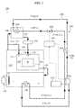
- FIG. 1 is a conceptual diagram (block diagram) showing a vacuum cleaning apparatus 100.
- the flow of a hydrocarbon-based cleaning agent is shown by arrows of solid lines
- the flow of a heat medium is shown by arrows of dashed lines
- the flow of signals is shown by arrows of dashed-dotted lines.
- the vacuum cleaning apparatus 100 includes a vacuum vessel 104 inside which a cleaning chamber 102 is provided.
- the vacuum vessel 104 is provided with an opening (not shown), and the opening is capable of being opened and closed by an opening and closing door (not shown).
- the opening and closing door is opened, the work W is carried into the cleaning chamber 102 through the opening and is mounted on a mounting table 108, the opening and closing door is closed, and the work W is cleaned. Thereafter, the opening and closing door is opened again, and the work W is carried out of the opening.
- the cleaning chamber 102 is provided with a shower unit 110.
- a vapor chamber 150 is communicated with the shower unit 110 via a vapor supply pipe 114, a condensing chamber 120, a condensed cleaning agent supply pipe 122, a cleaning agent reservoir 124, and a condensed cleaning agent supply pipe 126 in sequence.
- the cleaning chamber 102 is provided with a vapor supply unit 130.
- the vapor supply unit 130 is communicated with the vapor chamber 150 via a vapor supply pipe 114.
- the vapor chamber 150 is provided with a heater 152 and a condenser 240, and generates vapor of a hydrocarbon-based cleaning agent (hereinafter, merely referred to as the "vapor") by heating the hydrocarbon-based cleaning agent (solvent) to, for example, a temperature between about 80 and 140 °C, preferably to about 120 °C.
- the vapor generated in the vapor chamber 150 is imported into the condensing chamber 120 via the vapor supply pipe 114 or is supplied into the cleaning chamber 102 through the vapor supply unit 130.
- the vapor supplied into the cleaning chamber 102 by the vapor supply unit 130 contacts the work W and thereby is condensed.
- a heating mechanism by the condenser 240 is described in detail later.
- hydrocarbon-based cleaning agent has no special limitation, it is preferable to use a cleaning agent of third petroleum from the viewpoint of safety.
- the hydrocarbon-based cleaning agent includes, for example, normal paraffinic, isoparaffinic, napthenic, and aromatic cleaning agents.
- a cleaning agent of third petroleum it is preferable to use Teclean N-20, Clean Sol G, Daphne® Solvent or the like, called a "cleaning solvent”.
- the condensing chamber 120 includes an evaporator 220.
- the vapor imported into the condensing chamber 120 is cooled by the evaporator 220 and is condensed into the liquid hydrocarbon-based cleaning agent (hereinafter, merely referred to as the "condensed cleaning agent").
- the condensed cleaning agent is stored in the cleaning agent reservoir 124 through the condensed cleaning agent supply pipe 122, and thereafter is supplied into the cleaning chamber 102 through the condensed cleaning agent supply pipe 126 and the shower unit 110.
- a cooling mechanism by the evaporator 220 is described in detail later.
- the used cleaning agent imported into the vapor chamber 150 is again heated by the heater 152 or by the condenser 240 described above and thereby becomes vapor.
- the cleaning agent circulates through the vapor chamber 150, the vapor supply pipe 114, the condensing chamber 120, the condensed cleaning agent supply pipe 122, the cleaning agent reservoir 124, the condensed cleaning agent supply pipe 126, the shower unit 110, the cleaning chamber 102, and the used cleaning agent import pipe 128.
- a vacuum pump (not shown) is connected to the cleaning chamber 102 and to the vapor chamber 150.
- the vacuum pump vacuums (initially vacuums) the inside of the vacuum vessel 104 (the cleaning chamber 102) and thereby decreases the pressure of the inside to a predetermined pressure (for example, 6 kPa).
- the cleaning chamber 102 is connected with a pipe (not shown) used to open the cleaning chamber 102 to the atmosphere.
- the pipe is provided with an atmosphere-opening valve capable of blocking the communication between the atmosphere and the cleaning chamber 102.
- the atmosphere-opening valve opens the cleaning chamber 102 to the atmosphere and thus returns the internal pressure of the cleaning chamber 102 to the atmospheric pressure.
- a heat pump unit 200 includes a circulation passageway 210 (shown by reference numerals 210a to 210f in FIG. 1 ), the evaporator 220, a compressor 230, the condenser 240, an intermediate heat exchanger 250, an expansion valve 260, a pressure measurement unit 270, and a controller 280.
- a heat medium circulates through the circulation passageway 210 as shown by arrows of dashed lines in FIG. 1 , and is again imported into the evaporator 220 from the evaporator 220 through the intermediate heat exchanger 250, the compressor 230, the condenser 240, the intermediate heat exchanger 250, the expansion valve 260, which are provided in the circulation passageway 210.
- the kind of heat medium has no special limitation, it is preferable to use a chlorofluorocarbon-based heat medium (for example, R-245fa (1,1,1,3,3-Pentafluoropropane)) which is liquid at normal temperature under the atmospheric pressure and whose latent heat can be used at the evaporator 220.
- the normal temperature is, for example, 25 °C.
- the evaporator 220 is disposed on the downstream side of the expansion valve 260 in the circulation passageway 210.
- the evaporator 220 performs in the condensing chamber 120, heat exchange between a heat medium and vapor of a hydrocarbon-based cleaning agent imported from the vapor chamber 150, and thereby condenses (cools) the vapor into a condensed cleaning agent, and heats and vaporizes the heat medium. That is, the heat medium is heated by the evaporator 220, and thereby becomes gas (shown by reference signs G in FIG. 1 ).
- the heat medium heated by the evaporator 220 is further heated by the intermediate heat exchanger 250. A heating mechanism by the intermediate heat exchanger 250 is described in detail later.
- the compressor 230 is configured of, for example, a reciprocating compressor, and includes a compression mechanism and an accommodation space accommodating lubricating oil which is supplied to the compression mechanism.
- the compressor 230 adiabatically compresses the heat medium heated by the intermediate heat exchanger 250, and thus further heats the heat medium. That is, the compressor 230 increases the temperature of the heat medium by adiabatically compressing the heat medium.
- the specific configuration of the compressor 230 is described in detail later.
- the condenser 240 is disposed on the downstream side of the compressor 230 in the circulation passageway 210.
- the condenser 240 performs in the vapor chamber 150, heat exchange between the heat medium heated (the temperature of the heat medium has been increased) by the compressor 230 and a liquid hydrocarbon-based cleaning agent, and thereby heats the hydrocarbon-based cleaning agent and generates vapor of the hydrocarbon-based cleaning agent, and at the same time, cools and condenses the heat medium.
- the heat medium is cooled by the condenser 240, and thereby becomes a gas-liquid mixed state (shown by reference signs G, L in FIG. 1 ).
- the intermediate heat exchanger 250 performs heat exchange between the heat medium flowing through the circulation passageways 210a and 210b (passageway between the evaporator 220 and the compressor 230) and the heat medium flowing through the circulation passageways 210d and 210e (passageway between the condenser 240 and the expansion valve 260).
- the heat medium which has been heated by the evaporator 220 and flows through the circulation passageway 210a, may not be completely vaporized and may be a gas-liquid mixed state. In this case, if the liquid heat medium is imported into the compressor 230, a malfunction of the compressor 230 may occur.
- the heat medium flowing through the circulation passageway 210a is heated and the temperature of the heat medium is set to be higher than the saturation temperature thereof, and thereby the heat medium imported into the compressor 230 (the heat medium flowing through the circulation passageway 210b) can be reliably made to be only gas. Accordingly, it is possible to avoid a situation where a malfunction of the compressor 230 occurs.
- the expansion valve 260 is a valve which causes pressure reduction of a fluid, and is provided on the downstream side of the condenser 240.
- the expansion valve 260 further cools the heat medium by decompressing and expanding the heat medium condensed (cooled) by the condenser 240.
- the heat medium is cooled by the expansion valve 260, and thereby becomes liquid (shown by a reference sign L in FIG. 1 ).
- the heat medium cooled at the expansion valve 260 is again imported into the evaporator 220 through the circulation passageway 210f.
- the pressure measurement unit 270 measures the pressure of gas inside the accommodation space (described later) of the compressor 230.
- the controller 280 is configured of a semiconductor integrated circuit including a CPU (central processing unit), reads out a program, parameters or the like, which are used to operate the CPU, from a ROM, and manages and controls the entire heat pump unit 200 while working together with a RAM being a work area or with another electronic circuit.
- the controller 280 controls the drive level (drive) of the compressor 230 and the opening degree of the expansion valve 260 based on the pressure measured by the pressure measurement unit 270, and thereby controls the circulating amount of the heat medium in the circulation passageway 210.
- the heat medium may dissolve in the lubricating oil accommodated in the compressor 230.
- the operation is described that the heat medium dissolves in the lubricating oil accommodated in the compressor 230.
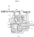
- FIG. 2 is a diagram showing the structure of the compressor 230.
- the flow of the heat medium is shown by arrows of solid lines
- the flow of the lubricating oil is shown by white arrows
- the lubricating oil is shown by the area filled with gray.
- pistons (compression mechanism) 232 of the compressor 230 are connected to a drive shaft (compression mechanism) 234, and when the drive shaft 234 is rotationally driven by a motor (not shown), the pistons 232 reciprocate relative to compression chambers 236 (cylinders).
- a drive unit other than the motor may be used in order to rotationally drive the drive shaft 234.
- the heat medium is imported into the compression chamber 236 from the circulation passageway 210b through an inlet 238a of the compressor 230.
- the heat medium imported into the compression chamber 236 is compressed through the compression operation of the piston 232, and thereafter is sent to the circulation passageway 210c from an outlet 238b at the time the piston 232 is positioned in the vicinity of the top dead center thereof.
- the inside of the compressor 230 is provided with the accommodation space R which accommodates the lubricating oil (for example, POE (polyol ester)), and the lubricating oil accommodated in the accommodation space R is supplied into an oil passageway 312 of the drive shaft 234 by a lubricating oil pump 310.
- the lubricating oil supplied into the oil passageway 312 is supplied to the outer circumferential surface of the piston 232 through an oil passageway (not shown) of the piston 232.
- the lubricating oil accommodated in the accommodation space R is supplied by a spraying portion 320 to the joint between the piston 232 and the drive shaft 234, or to the outer circumferential surface of the piston 232 and to the inner circumferential surface of the compression chamber 236 (cylinder).
- the lubricating oil is supplied to the outer circumferential surface of the piston 232 and to the inner circumferential surface of the compression chamber 236, and thereby the friction coefficient between the piston 232 and the compression chamber 236 is decreased, and wear of the piston 232 and the compression chamber 236 is reduced.
- the heat medium since the heat medium is imported into the compression chamber 236 of the heat pump unit 200, and the lubricating oil is supplied to the inner circumferential surface of the compression chamber 236, the heat medium may dissolve in the lubricating oil at the compression chamber 236.
- the lubricating oil in which the heat medium has dissolved, circulates through the circulation passageway 210. That is, the compression operation of the compressor 230 is continued in a state where the heat medium dissolves in the lubricating oil.
- the liquid heat medium may remain in the evaporator 220.
- the liquid heat medium remaining in the evaporator 220 is imported into the compressor 230 while keeping the liquid state, and thus a malfunction of the compressor 230 may occur.
- a heat medium used for the heat pump unit 200 of the vacuum cleaning apparatus 100 has a characteristic of more easily dissolving in lubricating oil than another heat medium used for a heat pump unit of a refrigerator, a freezer, an air conditioner, a water heater or the like (hereinafter, referred to as the "household electrical appliances").
- the household electrical appliances in order to generate vapor of a hydrocarbon-based cleaning agent in the vacuum cleaning apparatus 100, it is necessary to heat the hydrocarbon-based cleaning agent to a high temperature between, for example, about 80 to 140 °C.
- the boiling point of the heat medium used for the heat pump unit 200 of the vacuum cleaning apparatus 100 is higher than that of the heat medium used for a heat pump unit of the household electrical appliances or for a heat pump unit for general industry.
- the temperature at a compressor inlet of a heat medium used for a heat pump unit of the household electrical appliances is about 30 °C, and the temperature at a compressor outlet thereof is about 60 °C.
- the temperature at a compressor inlet of a heat medium used for a heat pump unit for general industry is about 90 °C, and the temperature at a compressor outlet thereof is about 110 °C.
- the temperature at the inlet 238a of the heat medium (the heat medium passing through the circulation passageway 210b) used for the heat pump unit 200 of the vacuum cleaning apparatus 100 is about 100 to 110 °C
- the temperature at the outlet 238b of the compressor 230 (the temperature of the heat medium passing through the circulation passageway 210c) is about 140 °C.
- the heat medium having a comparatively high boiling point generally has greater solubility in the lubricating oil of the compressor 230 included in the heat pump unit 200 than that of the heat medium having a comparatively low boiling point.
- the heat medium used for a heat pump unit of the household electrical appliances only a few percentages thereof dissolves in the lubricating oil of the compressor.
- about 20 percentages thereof may dissolve in the lubricating oil of the compressor 230.
- the generation of bubbles of the heat medium thereof may become remarkable compared to the compressor of a heat pump unit of the household electrical appliances, and there is a high possibility that the compressor 230 is damaged due to a decrease in height of the liquid surface LH of the lubricating oil.
- the generation of bubbles of the heat medium is caused by evaporation of the liquid heat medium, if the heat medium in the lubricating oil evaporates, the height of the liquid surface LH of the lubricating oil decreases.
- the controller 280 adjusts the opening degree of the expansion valve 260 when stopping the compressor 230, and thus limits the generation of bubbles of the heat medium inside the accommodation space R of the compressor 230.
- stopping control of the compressor 230 by the controller 280 is described.
- the controller 280 When the controller 280 receives instructions to stop the heat pump unit 200, namely instructions to stop the compression operation on the heat medium by the compressor 230, the controller 280 decreases the opening degree of the expansion valve 260 so that the height of the liquid surface LH of the lubricating oil accommodated in the accommodation space R of the compressor 230 is not less than a threshold preset for the compressor 230. That is, the controller 280 decreases the opening of the expansion valve 260 so that the height of the liquid surface LH of the lubricating oil accommodated in the accommodation space R is maintained to be greater than or equal to the threshold preset for the compressor 230.
- the threshold preset for the compressor 230 is the lower limit for the height of the liquid surface of the lubricating oil required for lubrication of the joint between the piston 232 and the drive shaft 234 or for lubrication between the outer circumferential surface of the piston 232 and the inner circumferential surface of the compression chamber 236. Therefore, if the height of the liquid surface LH of the lubricating oil is maintained to be greater than or equal to the threshold, it is possible to maintain appropriate lubrication on components of the compressor 230.
- the instructions to stop the heat pump unit 200 may be input into the controller 280 by an operator through an input device or the like, or may be received from another control device or the like.
- the controller 280 decreases the opening degree of the expansion valve 260 so that the height of the liquid surface LH of the lubricating oil accommodated in the accommodation space R of the compressor 230 is not less than the threshold preset for the compressor 230, for example, one of the following four methods is used.
- the controller 280 decreases the opening degree of the expansion valve 260 so that the changing rate of the opening degree of the expansion valve 260 is maintained to be a predetermined first value, and thereby the height of the liquid surface LH of the lubricating oil accommodated in the accommodation space R does not become less than the threshold.
- the first value is, for example, 3% / min.
- the controller 280 decreases the opening degree of the expansion valve 260 so that the decreasing rate of the pressure of the accommodation space R measured by the pressure measurement unit 270 is maintained to be a predetermined second value, and thereby the height of the liquid surface LH of the lubricating oil accommodated in the accommodation space R does not become less than the threshold.
- the second value is, for example, a decreasing rate of (10% of the pressure at the normal operation of the compressor 230) / min or less.
- the second value is 50 kPa / min.
- the compressor 230 is provided with a liquid level gauge, and the controller 280 decreases the opening degree of the expansion valve 260 so that the height of the liquid surface LH of the lubricating oil accommodated in the accommodation space R of the compressor 230 is not less than a preset threshold for the compressor 230.
- the liquid level gauge can be configured of existing technologies such as an optical sensor and an image-processing device.
- the compressor 230 is provided with a device used to measure a bubble amount (the amount of bubbles generated through bubbling of the heat medium), and the controller 280 decreases the opening degree of the expansion valve 260 so that the amount of bubbles generated in the accommodation space R of the compressor 230 is not greater than or equal to a predetermined amount.
- the predetermined amount is the upper limit for the bubble amount capable of maintaining lubrication (lubrication using lubricating oil) of the joint between the piston 232 and the drive shaft 234 or lubrication between the outer circumferential surface of the piston 232 and the inner circumferential surface of the compression chamber 236.
- the device used to measure the bubble amount can be configured of existing technologies such as a void fraction meter, an optical sensor, and an image-processing device.
- the opening degree of the expansion valve 260 is decreased based on the value described in the above opening adjustments 1 to 4, and thereby it is possible to prevent the height of the liquid surface LH of the lubricating oil accommodated in the accommodation space R of the compressor 230 from becoming less than a preset threshold for the compressor 230.
- the bubbling amount (evaporation amount) of the heat medium increases, the liquid surface LH of the lubricating oil declines, and thus they have a correlation.
- the bubbling amount (the bubbling amount per unit time) of the heat medium can be limited to be less than or equal to a constant value, and thus it is possible to prevent sudden generation of bubbles of the heat medium.
- the pressure in the accommodation space R can be gradually decreased before the drive of the compressor 230 is stopped, and it is possible to limit the generation of bubbles of the heat medium dissolving in the lubricating oil.
- the controller 280 continues the compression operation on the heat medium using the compressor 230 until the pressure of the accommodation space R measured by the pressure measurement unit 270 becomes less than a pressure (hereinafter, referred to as the "corresponding pressure") corresponding to a predetermined density of the heat medium contained in the lubricating oil after completely closing the expansion valve 260 and thereby blocking the inflow of the heat medium into the compressor 230 through the expansion valve 260.
- the corresponding pressure is, for example, 40 kPa (Abs).
- the controller 280 stops the drive of the compressor 230 after completely closing the expansion valve 260, it is possible to prevent the liquid heat medium from remaining in the evaporator 220. Therefore, when the controller 280 starts the operation of the heat pump unit 200 next time, no liquid heat medium is imported into the compressor 230, and thus damage to the compressor 230 can be prevented.
- the controller 280 maintains (continues) the compression operation on the heat medium using the compressor 230 until the pressure of the accommodation space R measured by the pressure measurement unit 270 becomes less than the corresponding pressure after completely closing the expansion valve 260, and thereby it is possible to evaporate the heat medium dissolving in the lubricating oil.
- the heat medium can be removed from the lubricating oil, and when the operation of the heat pump unit 200 is started next time, it is possible to limit the generation of bubbles of the heat medium in the lubricating oil, that is, to limit the decline amount of the liquid surface LH of the lubricating oil.
- FIG. 3 is a flowchart showing the flow of processing of the operation method of the heat pump unit 200.
- the stopping control of the heat pump unit 200 is performed during operation of the heat pump unit 200.
- the controller 280 When the controller 280 receives instructions to stop the compression operation on the heat medium using the compressor 230 in accordance with operation and input by an operator ("YES" at step S410), the controller 280 decreases the opening degree of the expansion valve 260 so that the height of the liquid surface LH of the lubricating oil accommodated in the accommodation space R of the compressor 230 is not less than a threshold A preset for the compressor 230 (step S412).
- the controller 280 determines whether or not the expansion valve 260 is completely closed (step S414), and if the expansion valve 260 is not completely closed ("NO" at step S414), the controller 280 continues processing of the step S412. In addition, the step S414 is performed again.
- the controller 280 determines whether or not the pressure of the accommodation space R of the compressor 230 measured by the pressure measurement unit 270 is less than the corresponding pressure (step S416). If the pressure of the accommodation space R is not less than the corresponding pressure ("NO" at step S416), the controller 280 continues the drive of the compressor 230, and performs the step S416 again. When the pressure of the accommodation space R becomes less than the corresponding pressure ("YES" at step S416), the controller 280 stops the drive of the compressor 230 (step S418).
- heat pump unit 200 included in the vacuum cleaning apparatus 100 is described in the above embodiment as an example, an apparatus, on which the heat pump unit 200 is mounted, is not limited thereto.
- a heat medium may also dissolve in lubricating oil of a compressor. Therefore, the heat pump unit 200 and the operation method of the heat pump unit 200 of the present invention can be applied to the above electrical equipment or the like.
- the above embodiment discloses a configuration in which the controller 280 continues the compression operation on the heat medium using the compressor 230 until the pressure of the accommodation space R measured by the pressure measurement unit 270 becomes less than the corresponding pressure after completely closing the expansion valve 260.
- the compression operation on the heat medium using the compressor 230 may be continued for the time estimated to be taken before the pressure becomes less than the corresponding pressure after the expansion valve 260 is completely closed. The time may be preset through experiment or the like.
- the intermediate heat exchanger 250 may not be provided therein. Even if the intermediate heat exchanger 250 is not provided, it is possible to limit the generation of bubbles of the heat medium contained in lubricating oil when the compressor 230 is stopped, and thus to prevent damage to the compressor 230.
- the above embodiment discloses the vacuum cleaning apparatus 100 in which the cleaning using the condensed cleaning agent supplied from the shower unit 110 and the cleaning using vapor supplied from the vapor supply unit 130 are performed.
- an immersion room may be provided under the cleaning chamber 102 inside the vacuum vessel 104, and a work W may be cleaned by immersing the work W in the immersion room.
- a hydrocarbon-based cleaning agent (liquid) is stored in the immersion room, the amount of the hydrocarbon-based cleaning agent is sufficient to completely immerse the work W therein, and a heater used to heat the hydrocarbon-based cleaning agent is provided in the immersion room.
- an intermediate door is provided between the cleaning chamber 102 and the immersion room, and is configured to communicate the cleaning chamber 102 and the immersion room with each other and to block the communication.
- the hydrocarbon-based cleaning agent stored in the immersion room is one of or both of the condensed cleaning agent supplied from the shower unit 110 and the condensed cleaning agent supplied from the cleaning agent reservoir 124 through the condensed cleaning agent supply pipe 126.
- the mounting table 108 is provided with a lifting device, and thus is configured to be capable of vertically moving.
- the lifting device is driven in a state where the cleaning chamber 102 and the immersion room communicate with each other by opening the intermediate door, and thereby the work W is moved from the cleaning chamber 102 into the immersion room or from the immersion room into the cleaning chamber 102, and thus is cleaned.
- the present invention can be used for a heat pump unit and for a heat pump unit operation method.
Landscapes
- Engineering & Computer Science (AREA)
- Physics & Mathematics (AREA)
- Mechanical Engineering (AREA)
- Thermal Sciences (AREA)
- General Engineering & Computer Science (AREA)
- Compressor (AREA)
- Lubricants (AREA)
- Control Of Positive-Displacement Pumps (AREA)
Abstract
Description
- The present invention relates to a heat pump unit and a heat pump unit operation method.
- Priority is claimed on Japanese Patent Application No.
2013-082117, filed April 10, 2013 - In the related art, a heat pump unit is known including a compressor which heats a heat medium by adiabatically compressing the heat medium circulating through a circulation passageway, a condenser which condenses the heat medium by cooling the heat medium heated by the compressor, an expansion valve which cools the heat medium by decompressing and expanding the heat medium condensed by the condenser, and an evaporator which evaporates the heat medium by heating the heat medium cooled by the expansion valve. The heat pump unit is utilized for various fields such as a refrigerator, a freezer, an air conditioner, and a water heater.
- When the operation of the heat pump unit is stopped, for example, if the drive of the compressor is stopped without closing the expansion valve, a liquid heat medium remains in the evaporator. In this case, at the time the operation of the heat pump unit is started next time, the liquid heat medium remaining in the evaporator is imported into the compressor while keeping the liquid state, and thus a malfunction of the compressor may occur.
- Accordingly, a technology is disclosed in which when the operation of a heat pump unit including an expansion valve capable of being controlled so as to be opened or closed is stopped, the expansion valve is completely closed at one time before the drive of a compressor is stopped (for example, refer to Patent Document 1).
- [Patent Document 1] Japanese Unexamined Patent Application, First Publication No.
2001-165511 - A compression mechanism included in the compressor is supplied with lubricating oil, and in the heat pump unit, at the time the compressor adiabatically compresses a heat medium, the heat medium may dissolve in the lubricating oil. In this case, if the technology of Patent Document 1 is used and the expansion valve is completely closed at one time in a state where the compressor is being driven, the pressure inside the compressor suddenly decreases, and the heat medium dissolving in the lubricating oil may bubble.
- If the heat medium bubbles, the seeming viscosity of the lubricating oil decreases, an oil film of the lubricating oil may not be sufficiently formed in the compression mechanism, wear of the compression mechanism may be advanced, and thus the compressor may be damaged.
- An object of the present invention is to provide a heat pump unit and a heat pump unit operation method which can limit the generation of bubbles of a heat medium contained in lubricating oil at the time the compressor is stopped and thus can prevent damage to the compressor.
- In order to solve the above problems, a first aspect of the present invention is a heat pump unit including: a circulation passageway through which a heat medium circulates; a compressor which includes a compression mechanism and an accommodation space accommodating lubricating oil to be supplied to the compression mechanism, and which increases the temperature of the heat medium by adiabatically compressing the heat medium circulating through the circulation passageway; a condenser which is provided on a downstream side of the compressor in the circulation passageway, and which condenses the heat medium by cooling the heat medium whose temperature has been increased by the compressor; an expansion valve which is provided on a downstream side of the condenser in the circulation passageway, and which cools the heat medium by decompressing and expanding the heat medium condensed by the condenser; an evaporator which is provided on a downstream side of the expansion valve in the circulation passageway, and which evaporates the heat medium by heating the heat medium cooled by the expansion valve; and a controller which controls drive of the compressor and the opening degree of the expansion valve, and which controls the circulating amount of the heat medium in the circulation passageway. In addition, the controller is adapted to decrease the opening degree of the expansion valve so that the height of the liquid surface of the lubricating oil accommodated in the accommodation space is maintained to be greater than or equal to a threshold preset for the compressor, and to stop compression operation on the heat medium by the compressor after blocking inflow of the heat medium into the compressor through the expansion valve by completely closing the expansion valve, when the controller receives instructions to stop the compression operation on the heat medium by the compressor.
- A second aspect of the present invention is that in the heat pump unit of the first aspect, the controller is adapted to maintain the height of the liquid surface of the lubricating oil accommodated in the accommodation space to be greater than or equal to the threshold by decreasing the opening degree of the expansion valve so that the changing rate of the opening degree of the expansion valve is maintained to be a predetermined first value.
- A third aspect of the present invention is that in the heat pump unit of the first aspect, the controller is adapted to maintain the height of the liquid surface of the lubricating oil accommodated in the accommodation space to be greater than or equal to the threshold by decreasing the opening degree of the expansion valve so that the decreasing rate of the pressure of the accommodation space is maintained to be a predetermined second value.
- A fourth aspect of the present invention is that in the heat pump unit of any one of the first to third aspects, the controller is adapted to continue the compression operation on the heat medium by the compressor until the pressure of the accommodation space is less than a pressure corresponding to a predetermined density of the heat medium contained in the lubricating oil after completely closing the expansion valve, and to stop the compression operation on the heat medium by the compressor when the pressure of the accommodation space is less than the pressure corresponding to the predetermined density of the heat medium contained in the lubricating oil.
- In order to solve the above problems, a fifth aspect of the present invention is a heat pump unit operation method used for a heat pump unit, the heat pump unit including: a circulation passageway through which a heat medium circulates; a compressor which includes a compression mechanism and an accommodation space accommodating lubricating oil to be supplied to the compression mechanism, and which increases the temperature of the heat medium by adiabatically compressing the heat medium circulating through the circulation passageway; a condenser which is provided on a downstream side of the compressor in the circulation passageway, and which condenses the heat medium by cooling the heat medium whose temperature has been increased by the compressor; an expansion valve which is provided on a downstream side of the condenser in the circulation passageway, and which cools the heat medium by decompressing and expanding the heat medium condensed by the condenser; and an evaporator which is provided on a downstream side of the expansion valve in the circulation passageway, and which evaporates the heat medium by heating the heat medium cooled by the expansion valve. The operation method includes a step of decreasing the opening degree of the expansion valve so that the height of the liquid surface of the lubricating oil accommodated in the accommodation space is maintained to be greater than or equal to a threshold preset for the compressor, and of stopping compression operation on the heat medium by the compressor after blocking inflow of the heat medium into the compressor through the expansion valve by completely closing the expansion valve, based on instructions to stop the compression operation on the heat medium by the compressor.
- According to the present invention, it is possible to limit the generation of bubbles of a heat medium contained in lubricating oil at the time the compressor is stopped, and thus to prevent damage to the compressor.
-
-
FIG. 1 is a conceptual diagram showing a vacuum cleaning apparatus. -
FIG. 2 is a diagram showing the structure of a compressor. -
FIG. 3 is a flowchart showing the flow of processing of a heat pump unit operation method. - Hereinafter, preferable embodiments of the present invention are described in detail with reference to the attached drawings. Dimensions, materials, other specific numerical values and the like shown in the embodiments are merely examples which facilitate understanding of the present invention and do not limit the present invention other than a case where a special description limiting it is provided. Additionally, in the specification and drawings, components having substantially the same function and structure are represented by the same reference sign, and a duplicate description thereof is omitted. Furthermore, the illustrations of components not directly relating to the present invention are omitted.
- In the related art, a heat pump unit is provided in various kinds of electrical equipment such as a refrigerator, a freezer, an air conditioner, and a water heater. Additionally, in recent years, a vacuum cleaning apparatus, which cleans a work (processing object) under decreased pressure using vapor of a hydrocarbon-based cleaning agent, has been developed, and the heat pump unit is also utilized for the vacuum cleaning apparatus. The work denotes, for example, an industrial product, and the vacuum cleaning apparatus cleans the work and removes contamination adhering to the work. In this embodiment, a vacuum cleaning apparatus being an example of the apparatus including a heat pump unit is described.
-
FIG. 1 is a conceptual diagram (block diagram) showing avacuum cleaning apparatus 100. InFIG. 1 , the flow of a hydrocarbon-based cleaning agent is shown by arrows of solid lines, the flow of a heat medium is shown by arrows of dashed lines, and the flow of signals is shown by arrows of dashed-dotted lines. As shown inFIG. 1 , thevacuum cleaning apparatus 100 includes avacuum vessel 104 inside which acleaning chamber 102 is provided. Thevacuum vessel 104 is provided with an opening (not shown), and the opening is capable of being opened and closed by an opening and closing door (not shown). Thus, when a work W is cleaned, the opening and closing door is opened, the work W is carried into thecleaning chamber 102 through the opening and is mounted on a mounting table 108, the opening and closing door is closed, and the work W is cleaned. Thereafter, the opening and closing door is opened again, and the work W is carried out of the opening. - The
cleaning chamber 102 is provided with ashower unit 110. In addition, avapor chamber 150 is communicated with theshower unit 110 via avapor supply pipe 114, acondensing chamber 120, a condensed cleaningagent supply pipe 122, acleaning agent reservoir 124, and a condensed cleaningagent supply pipe 126 in sequence. - The
cleaning chamber 102 is provided with avapor supply unit 130. Thevapor supply unit 130 is communicated with thevapor chamber 150 via avapor supply pipe 114. - The
vapor chamber 150 is provided with aheater 152 and acondenser 240, and generates vapor of a hydrocarbon-based cleaning agent (hereinafter, merely referred to as the "vapor") by heating the hydrocarbon-based cleaning agent (solvent) to, for example, a temperature between about 80 and 140 °C, preferably to about 120 °C. The vapor generated in thevapor chamber 150 is imported into thecondensing chamber 120 via thevapor supply pipe 114 or is supplied into thecleaning chamber 102 through thevapor supply unit 130. The vapor supplied into thecleaning chamber 102 by thevapor supply unit 130 contacts the work W and thereby is condensed. A heating mechanism by thecondenser 240 is described in detail later. - Although the kind of hydrocarbon-based cleaning agent has no special limitation, it is preferable to use a cleaning agent of third petroleum from the viewpoint of safety. The hydrocarbon-based cleaning agent includes, for example, normal paraffinic, isoparaffinic, napthenic, and aromatic cleaning agents. Specifically, as a cleaning agent of third petroleum, it is preferable to use Teclean N-20, Clean Sol G, Daphne® Solvent or the like, called a "cleaning solvent".
- The
condensing chamber 120 includes anevaporator 220. The vapor imported into thecondensing chamber 120 is cooled by theevaporator 220 and is condensed into the liquid hydrocarbon-based cleaning agent (hereinafter, merely referred to as the "condensed cleaning agent"). The condensed cleaning agent is stored in thecleaning agent reservoir 124 through the condensed cleaningagent supply pipe 122, and thereafter is supplied into thecleaning chamber 102 through the condensed cleaningagent supply pipe 126 and theshower unit 110. A cooling mechanism by theevaporator 220 is described in detail later. - The condensed cleaning agent which has cleaned the work W after being supplied from the
shower unit 110, or the condensed cleaning agent generated by condensing at the work W, vapor supplied from thevapor supply unit 130, is again imported into thevapor chamber 150 through a used cleaningagent import pipe 128. The used cleaning agent imported into thevapor chamber 150 is again heated by theheater 152 or by thecondenser 240 described above and thereby becomes vapor. In this way, the cleaning agent circulates through thevapor chamber 150, thevapor supply pipe 114, thecondensing chamber 120, the condensed cleaningagent supply pipe 122, thecleaning agent reservoir 124, the condensed cleaningagent supply pipe 126, theshower unit 110, thecleaning chamber 102, and the used cleaningagent import pipe 128. - A vacuum pump (not shown) is connected to the
cleaning chamber 102 and to thevapor chamber 150. In a decompression step before the cleaning of the work W is started, the vacuum pump vacuums (initially vacuums) the inside of the vacuum vessel 104 (the cleaning chamber 102) and thereby decreases the pressure of the inside to a predetermined pressure (for example, 6 kPa). Furthermore, thecleaning chamber 102 is connected with a pipe (not shown) used to open thecleaning chamber 102 to the atmosphere. The pipe is provided with an atmosphere-opening valve capable of blocking the communication between the atmosphere and thecleaning chamber 102. In a unloading step after a cleaning step and a drying step of the work W are finished, the atmosphere-opening valve opens thecleaning chamber 102 to the atmosphere and thus returns the internal pressure of thecleaning chamber 102 to the atmospheric pressure. - A
heat pump unit 200 includes a circulation passageway 210 (shown byreference numerals 210a to 210f inFIG. 1 ), theevaporator 220, acompressor 230, thecondenser 240, anintermediate heat exchanger 250, anexpansion valve 260, apressure measurement unit 270, and acontroller 280. In theheat pump unit 200, a heat medium circulates through thecirculation passageway 210 as shown by arrows of dashed lines inFIG. 1 , and is again imported into theevaporator 220 from theevaporator 220 through theintermediate heat exchanger 250, thecompressor 230, thecondenser 240, theintermediate heat exchanger 250, theexpansion valve 260, which are provided in thecirculation passageway 210. In addition, although the kind of heat medium has no special limitation, it is preferable to use a chlorofluorocarbon-based heat medium (for example, R-245fa (1,1,1,3,3-Pentafluoropropane)) which is liquid at normal temperature under the atmospheric pressure and whose latent heat can be used at theevaporator 220. The normal temperature is, for example, 25 °C. - The
evaporator 220 is disposed on the downstream side of theexpansion valve 260 in thecirculation passageway 210. Theevaporator 220 performs in the condensingchamber 120, heat exchange between a heat medium and vapor of a hydrocarbon-based cleaning agent imported from thevapor chamber 150, and thereby condenses (cools) the vapor into a condensed cleaning agent, and heats and vaporizes the heat medium. That is, the heat medium is heated by theevaporator 220, and thereby becomes gas (shown by reference signs G inFIG. 1 ). The heat medium heated by theevaporator 220 is further heated by theintermediate heat exchanger 250. A heating mechanism by theintermediate heat exchanger 250 is described in detail later. - The
compressor 230 is configured of, for example, a reciprocating compressor, and includes a compression mechanism and an accommodation space accommodating lubricating oil which is supplied to the compression mechanism. Thecompressor 230 adiabatically compresses the heat medium heated by theintermediate heat exchanger 250, and thus further heats the heat medium. That is, thecompressor 230 increases the temperature of the heat medium by adiabatically compressing the heat medium. The specific configuration of thecompressor 230 is described in detail later. - The
condenser 240 is disposed on the downstream side of thecompressor 230 in thecirculation passageway 210. Thecondenser 240 performs in thevapor chamber 150, heat exchange between the heat medium heated (the temperature of the heat medium has been increased) by thecompressor 230 and a liquid hydrocarbon-based cleaning agent, and thereby heats the hydrocarbon-based cleaning agent and generates vapor of the hydrocarbon-based cleaning agent, and at the same time, cools and condenses the heat medium. The heat medium is cooled by thecondenser 240, and thereby becomes a gas-liquid mixed state (shown by reference signs G, L inFIG. 1 ). - The
intermediate heat exchanger 250 performs heat exchange between the heat medium flowing through thecirculation passageways evaporator 220 and the compressor 230) and the heat medium flowing through thecirculation passageways condenser 240 and the expansion valve 260). The heat medium, which has been heated by theevaporator 220 and flows through thecirculation passageway 210a, may not be completely vaporized and may be a gas-liquid mixed state. In this case, if the liquid heat medium is imported into thecompressor 230, a malfunction of thecompressor 230 may occur. - Therefore, in a configuration including the
intermediate heat exchanger 250, the heat medium flowing through thecirculation passageway 210a is heated and the temperature of the heat medium is set to be higher than the saturation temperature thereof, and thereby the heat medium imported into the compressor 230 (the heat medium flowing through thecirculation passageway 210b) can be reliably made to be only gas. Accordingly, it is possible to avoid a situation where a malfunction of thecompressor 230 occurs. - The
expansion valve 260 is a valve which causes pressure reduction of a fluid, and is provided on the downstream side of thecondenser 240. Theexpansion valve 260 further cools the heat medium by decompressing and expanding the heat medium condensed (cooled) by thecondenser 240. The heat medium is cooled by theexpansion valve 260, and thereby becomes liquid (shown by a reference sign L inFIG. 1 ). The heat medium cooled at theexpansion valve 260 is again imported into theevaporator 220 through thecirculation passageway 210f. - The
pressure measurement unit 270 measures the pressure of gas inside the accommodation space (described later) of thecompressor 230. - The
controller 280 is configured of a semiconductor integrated circuit including a CPU (central processing unit), reads out a program, parameters or the like, which are used to operate the CPU, from a ROM, and manages and controls the entireheat pump unit 200 while working together with a RAM being a work area or with another electronic circuit. In this embodiment, thecontroller 280 controls the drive level (drive) of thecompressor 230 and the opening degree of theexpansion valve 260 based on the pressure measured by thepressure measurement unit 270, and thereby controls the circulating amount of the heat medium in thecirculation passageway 210. - As described above, the heat medium may dissolve in the lubricating oil accommodated in the
compressor 230. Hereinafter, with reference toFIG. 2 , the operation is described that the heat medium dissolves in the lubricating oil accommodated in thecompressor 230. -
FIG. 2 is a diagram showing the structure of thecompressor 230. InFIG. 2 , the flow of the heat medium is shown by arrows of solid lines, the flow of the lubricating oil is shown by white arrows, and the lubricating oil is shown by the area filled with gray. As shown inFIG. 2 , pistons (compression mechanism) 232 of thecompressor 230 are connected to a drive shaft (compression mechanism) 234, and when thedrive shaft 234 is rotationally driven by a motor (not shown), thepistons 232 reciprocate relative to compression chambers 236 (cylinders). In addition, a drive unit other than the motor may be used in order to rotationally drive thedrive shaft 234. At the time thepiston 232 is positioned in the vicinity of the bottom dead center thereof, the heat medium is imported into thecompression chamber 236 from thecirculation passageway 210b through aninlet 238a of thecompressor 230. The heat medium imported into thecompression chamber 236 is compressed through the compression operation of thepiston 232, and thereafter is sent to thecirculation passageway 210c from anoutlet 238b at the time thepiston 232 is positioned in the vicinity of the top dead center thereof. - As shown in
FIG. 2 , the inside of thecompressor 230 is provided with the accommodation space R which accommodates the lubricating oil (for example, POE (polyol ester)), and the lubricating oil accommodated in the accommodation space R is supplied into anoil passageway 312 of thedrive shaft 234 by a lubricatingoil pump 310. The lubricating oil supplied into theoil passageway 312 is supplied to the outer circumferential surface of thepiston 232 through an oil passageway (not shown) of thepiston 232. In addition, the lubricating oil accommodated in the accommodation space R is supplied by a sprayingportion 320 to the joint between thepiston 232 and thedrive shaft 234, or to the outer circumferential surface of thepiston 232 and to the inner circumferential surface of the compression chamber 236 (cylinder). In this way, the lubricating oil is supplied to the outer circumferential surface of thepiston 232 and to the inner circumferential surface of thecompression chamber 236, and thereby the friction coefficient between thepiston 232 and thecompression chamber 236 is decreased, and wear of thepiston 232 and thecompression chamber 236 is reduced. - In this way, since the heat medium is imported into the
compression chamber 236 of theheat pump unit 200, and the lubricating oil is supplied to the inner circumferential surface of thecompression chamber 236, the heat medium may dissolve in the lubricating oil at thecompression chamber 236. In this case, the lubricating oil, in which the heat medium has dissolved, circulates through thecirculation passageway 210. That is, the compression operation of thecompressor 230 is continued in a state where the heat medium dissolves in the lubricating oil. - As described above, when the operation of the
heat pump unit 200 is stopped, if the drive of thecompressor 230 is stopped without closing theexpansion valve 260, the liquid heat medium may remain in theevaporator 220. In this state, when the operation of theheat pump unit 200 is started next time, the liquid heat medium remaining in theevaporator 220 is imported into thecompressor 230 while keeping the liquid state, and thus a malfunction of thecompressor 230 may occur. On the other hand, when theheat pump unit 200 is stopped, if theexpansion valve 260 is completely closed at one time in a state where thecompressor 230 is driven in order to prevent the liquid heat medium from remaining in theevaporator 220, the pressure inside the accommodation space R of thecompressor 230 suddenly decreases, the heat medium dissolving in the lubricating oil of thecompressor 230 may bubble, and thus thecompressor 230 may be damaged. For example, bubbles of the heat medium may reach thecompression chamber 236. - Particularly, a heat medium used for the
heat pump unit 200 of thevacuum cleaning apparatus 100 has a characteristic of more easily dissolving in lubricating oil than another heat medium used for a heat pump unit of a refrigerator, a freezer, an air conditioner, a water heater or the like (hereinafter, referred to as the "household electrical appliances"). Specifically, in order to generate vapor of a hydrocarbon-based cleaning agent in thevacuum cleaning apparatus 100, it is necessary to heat the hydrocarbon-based cleaning agent to a high temperature between, for example, about 80 to 140 °C. Thus, the boiling point of the heat medium used for theheat pump unit 200 of thevacuum cleaning apparatus 100 is higher than that of the heat medium used for a heat pump unit of the household electrical appliances or for a heat pump unit for general industry. For example, the temperature at a compressor inlet of a heat medium used for a heat pump unit of the household electrical appliances is about 30 °C, and the temperature at a compressor outlet thereof is about 60 °C. The temperature at a compressor inlet of a heat medium used for a heat pump unit for general industry is about 90 °C, and the temperature at a compressor outlet thereof is about 110 °C. In contrast, the temperature at theinlet 238a of the heat medium (the heat medium passing through thecirculation passageway 210b) used for theheat pump unit 200 of thevacuum cleaning apparatus 100 is about 100 to 110 °C, and the temperature at theoutlet 238b of the compressor 230 (the temperature of the heat medium passing through thecirculation passageway 210c) is about 140 °C. - The heat medium having a comparatively high boiling point generally has greater solubility in the lubricating oil of the
compressor 230 included in theheat pump unit 200 than that of the heat medium having a comparatively low boiling point. Specifically, in the heat medium used for a heat pump unit of the household electrical appliances, only a few percentages thereof dissolves in the lubricating oil of the compressor. In contrast, in the heat medium used for theheat pump unit 200 of thevacuum cleaning apparatus 100, about 20 percentages thereof may dissolve in the lubricating oil of thecompressor 230. Thus, in thecompressor 230 of theheat pump unit 200 of thevacuum cleaning apparatus 100, the generation of bubbles of the heat medium thereof may become remarkable compared to the compressor of a heat pump unit of the household electrical appliances, and there is a high possibility that thecompressor 230 is damaged due to a decrease in height of the liquid surface LH of the lubricating oil. In addition, since the generation of bubbles of the heat medium is caused by evaporation of the liquid heat medium, if the heat medium in the lubricating oil evaporates, the height of the liquid surface LH of the lubricating oil decreases. If the height of the liquid surface LH decreases, and the amount of the lubricating oil cannot be secured which is required for lubrication of the joint between thepiston 232 and thedrive shaft 234 or for lubrication between the outer circumferential surface of thepiston 232 and the inner circumferential surface of thecompression chamber 236, wear of components may be advanced, and thecompressor 230 may be damaged. - Accordingly, the
controller 280 adjusts the opening degree of theexpansion valve 260 when stopping thecompressor 230, and thus limits the generation of bubbles of the heat medium inside the accommodation space R of thecompressor 230. Hereinafter, stopping control of thecompressor 230 by thecontroller 280 is described. - When the
controller 280 receives instructions to stop theheat pump unit 200, namely instructions to stop the compression operation on the heat medium by thecompressor 230, thecontroller 280 decreases the opening degree of theexpansion valve 260 so that the height of the liquid surface LH of the lubricating oil accommodated in the accommodation space R of thecompressor 230 is not less than a threshold preset for thecompressor 230. That is, thecontroller 280 decreases the opening of theexpansion valve 260 so that the height of the liquid surface LH of the lubricating oil accommodated in the accommodation space R is maintained to be greater than or equal to the threshold preset for thecompressor 230. The threshold preset for thecompressor 230 is the lower limit for the height of the liquid surface of the lubricating oil required for lubrication of the joint between thepiston 232 and thedrive shaft 234 or for lubrication between the outer circumferential surface of thepiston 232 and the inner circumferential surface of thecompression chamber 236. Therefore, if the height of the liquid surface LH of the lubricating oil is maintained to be greater than or equal to the threshold, it is possible to maintain appropriate lubrication on components of thecompressor 230. In addition, the instructions to stop theheat pump unit 200 may be input into thecontroller 280 by an operator through an input device or the like, or may be received from another control device or the like. - When the
controller 280 decreases the opening degree of theexpansion valve 260 so that the height of the liquid surface LH of the lubricating oil accommodated in the accommodation space R of thecompressor 230 is not less than the threshold preset for thecompressor 230, for example, one of the following four methods is used. - The
controller 280 decreases the opening degree of theexpansion valve 260 so that the changing rate of the opening degree of theexpansion valve 260 is maintained to be a predetermined first value, and thereby the height of the liquid surface LH of the lubricating oil accommodated in the accommodation space R does not become less than the threshold. In a case where the opening degree at the time theexpansion valve 260 completely opens is 100%, the first value is, for example, 3% / min. - The
controller 280 decreases the opening degree of theexpansion valve 260 so that the decreasing rate of the pressure of the accommodation space R measured by thepressure measurement unit 270 is maintained to be a predetermined second value, and thereby the height of the liquid surface LH of the lubricating oil accommodated in the accommodation space R does not become less than the threshold. The second value is, for example, a decreasing rate of (10% of the pressure at the normal operation of the compressor 230) / min or less. Thus, in a case where the pressure at the normal operation of thecompressor 230 is, for example, 500 kPa, the second value is 50 kPa / min. - The
compressor 230 is provided with a liquid level gauge, and thecontroller 280 decreases the opening degree of theexpansion valve 260 so that the height of the liquid surface LH of the lubricating oil accommodated in the accommodation space R of thecompressor 230 is not less than a preset threshold for thecompressor 230. The liquid level gauge can be configured of existing technologies such as an optical sensor and an image-processing device. - The
compressor 230 is provided with a device used to measure a bubble amount (the amount of bubbles generated through bubbling of the heat medium), and thecontroller 280 decreases the opening degree of theexpansion valve 260 so that the amount of bubbles generated in the accommodation space R of thecompressor 230 is not greater than or equal to a predetermined amount. The predetermined amount is the upper limit for the bubble amount capable of maintaining lubrication (lubrication using lubricating oil) of the joint between thepiston 232 and thedrive shaft 234 or lubrication between the outer circumferential surface of thepiston 232 and the inner circumferential surface of thecompression chamber 236. The device used to measure the bubble amount can be configured of existing technologies such as a void fraction meter, an optical sensor, and an image-processing device. - The opening degree of the
expansion valve 260 is decreased based on the value described in the above opening adjustments 1 to 4, and thereby it is possible to prevent the height of the liquid surface LH of the lubricating oil accommodated in the accommodation space R of thecompressor 230 from becoming less than a preset threshold for thecompressor 230. In addition, as described above, if the bubbling amount (evaporation amount) of the heat medium increases, the liquid surface LH of the lubricating oil declines, and thus they have a correlation. Therefore, if the height of the liquid surface LH of the lubricating oil accommodated in the accommodation space R is maintained to be greater than or equal to the preset threshold, the bubbling amount (the bubbling amount per unit time) of the heat medium can be limited to be less than or equal to a constant value, and thus it is possible to prevent sudden generation of bubbles of the heat medium. - The pressure in the accommodation space R can be gradually decreased before the drive of the
compressor 230 is stopped, and it is possible to limit the generation of bubbles of the heat medium dissolving in the lubricating oil. Thus, it is possible to avoid a situation where the seeming viscosity of the lubricating oil decreases, and to sufficiently form oil films of the lubricating oil on slide members such as thepiston 232, thedrive shaft 234, and thecompression chamber 236. Therefore, it is possible to avoid a situation where the slide members are worn and thereby thecompressor 230 is damaged. - The
controller 280 continues the compression operation on the heat medium using thecompressor 230 until the pressure of the accommodation space R measured by thepressure measurement unit 270 becomes less than a pressure (hereinafter, referred to as the "corresponding pressure") corresponding to a predetermined density of the heat medium contained in the lubricating oil after completely closing theexpansion valve 260 and thereby blocking the inflow of the heat medium into thecompressor 230 through theexpansion valve 260. In addition, the corresponding pressure is, for example, 40 kPa (Abs). - In this way, since the
controller 280 stops the drive of thecompressor 230 after completely closing theexpansion valve 260, it is possible to prevent the liquid heat medium from remaining in theevaporator 220. Therefore, when thecontroller 280 starts the operation of theheat pump unit 200 next time, no liquid heat medium is imported into thecompressor 230, and thus damage to thecompressor 230 can be prevented. - The
controller 280 maintains (continues) the compression operation on the heat medium using thecompressor 230 until the pressure of the accommodation space R measured by thepressure measurement unit 270 becomes less than the corresponding pressure after completely closing theexpansion valve 260, and thereby it is possible to evaporate the heat medium dissolving in the lubricating oil. Thus, the heat medium can be removed from the lubricating oil, and when the operation of theheat pump unit 200 is started next time, it is possible to limit the generation of bubbles of the heat medium in the lubricating oil, that is, to limit the decline amount of the liquid surface LH of the lubricating oil. - Next, an operation method of the
heat pump unit 200, particularly a stopping method thereof, is described.FIG. 3 is a flowchart showing the flow of processing of the operation method of theheat pump unit 200. In addition, the stopping control of theheat pump unit 200 is performed during operation of theheat pump unit 200. - When the
controller 280 receives instructions to stop the compression operation on the heat medium using thecompressor 230 in accordance with operation and input by an operator ("YES" at step S410), thecontroller 280 decreases the opening degree of theexpansion valve 260 so that the height of the liquid surface LH of the lubricating oil accommodated in the accommodation space R of thecompressor 230 is not less than a threshold A preset for the compressor 230 (step S412). - Subsequently, the
controller 280 determines whether or not theexpansion valve 260 is completely closed (step S414), and if theexpansion valve 260 is not completely closed ("NO" at step S414), thecontroller 280 continues processing of the step S412. In addition, the step S414 is performed again. - On the other hand, if the
expansion valve 260 is completely closed ("YES" at step S414), thecontroller 280 determines whether or not the pressure of the accommodation space R of thecompressor 230 measured by thepressure measurement unit 270 is less than the corresponding pressure (step S416). If the pressure of the accommodation space R is not less than the corresponding pressure ("NO" at step S416), thecontroller 280 continues the drive of thecompressor 230, and performs the step S416 again. When the pressure of the accommodation space R becomes less than the corresponding pressure ("YES" at step S416), thecontroller 280 stops the drive of the compressor 230 (step S418). - As described above, according to the
heat pump unit 200 of this embodiment and to the operation method of theheat pump unit 200 of this embodiment, it is possible to limit the generation of bubbles of the heat medium contained in the lubricating oil when thecompressor 230 is stopped, and thus to prevent damage to thecompressor 230. - Hereinbefore, although the preferable embodiment of the present invention is described with reference to the attached drawings, the present invention is not limited to this embodiment. A person having ordinary skill in the art can make various modifications within the scope shown by the attached claims, and these modifications are naturally included in the technical scope of the present invention.
- Although the
heat pump unit 200 included in thevacuum cleaning apparatus 100 is described in the above embodiment as an example, an apparatus, on which theheat pump unit 200 is mounted, is not limited thereto. For example, in a heat pump unit mounted on various kinds of electrical equipment such as a refrigerator, a freezer, an air conditioner, and a water heater, a heat medium may also dissolve in lubricating oil of a compressor. Therefore, theheat pump unit 200 and the operation method of theheat pump unit 200 of the present invention can be applied to the above electrical equipment or the like. - The above embodiment discloses a configuration in which the
controller 280 continues the compression operation on the heat medium using thecompressor 230 until the pressure of the accommodation space R measured by thepressure measurement unit 270 becomes less than the corresponding pressure after completely closing theexpansion valve 260. However, the compression operation on the heat medium using thecompressor 230 may be continued for the time estimated to be taken before the pressure becomes less than the corresponding pressure after theexpansion valve 260 is completely closed. The time may be preset through experiment or the like. - Although the above embodiment discloses a configuration in which the
heat pump unit 200 includes theintermediate heat exchanger 250, theintermediate heat exchanger 250 may not be provided therein. Even if theintermediate heat exchanger 250 is not provided, it is possible to limit the generation of bubbles of the heat medium contained in lubricating oil when thecompressor 230 is stopped, and thus to prevent damage to thecompressor 230. - The above embodiment discloses the
vacuum cleaning apparatus 100 in which the cleaning using the condensed cleaning agent supplied from theshower unit 110 and the cleaning using vapor supplied from thevapor supply unit 130 are performed. However, for example, an immersion room may be provided under thecleaning chamber 102 inside thevacuum vessel 104, and a work W may be cleaned by immersing the work W in the immersion room. - Specifically, a hydrocarbon-based cleaning agent (liquid) is stored in the immersion room, the amount of the hydrocarbon-based cleaning agent is sufficient to completely immerse the work W therein, and a heater used to heat the hydrocarbon-based cleaning agent is provided in the immersion room. In addition, an intermediate door is provided between the cleaning
chamber 102 and the immersion room, and is configured to communicate thecleaning chamber 102 and the immersion room with each other and to block the communication. The hydrocarbon-based cleaning agent stored in the immersion room is one of or both of the condensed cleaning agent supplied from theshower unit 110 and the condensed cleaning agent supplied from thecleaning agent reservoir 124 through the condensed cleaningagent supply pipe 126. In this case, the mounting table 108 is provided with a lifting device, and thus is configured to be capable of vertically moving. Thus, the lifting device is driven in a state where thecleaning chamber 102 and the immersion room communicate with each other by opening the intermediate door, and thereby the work W is moved from thecleaning chamber 102 into the immersion room or from the immersion room into thecleaning chamber 102, and thus is cleaned. - It is not necessary to always perform the steps of the heat pump unit operation method of this specification in the order described in the flowchart, and the method may include a parallel or subroutine process.
- The present invention can be used for a heat pump unit and for a heat pump unit operation method.
-
- 200
- heat pump unit
- 210
- circulation passageway
- 220
- evaporator
- 230
- compressor
- 232
- piston (compression mechanism)
- 234
- drive shaft (compression mechanism)
- 240
- condenser
- 260
- expansion valve
- 270
- pressure measurement unit
- 280
- controller
- R
- accommodation space
Claims (7)
- A heat pump unit comprising:a circulation passageway through which a heat medium circulates;a compressor which includes a compression mechanism and an accommodation space accommodating lubricating oil to be supplied to the compression mechanism, and which increases the temperature of the heat medium by adiabatically compressing the heat medium circulating through the circulation passageway;a condenser which is provided on a downstream side of the compressor in the circulation passageway, and which condenses the heat medium by cooling the heat medium whose temperature has been increased by the compressor;an expansion valve which is provided on a downstream side of the condenser in the circulation passageway, and which cools the heat medium by decompressing and expanding the heat medium condensed by the condenser;an evaporator which is provided on a downstream side of the expansion valve in the circulation passageway, and which evaporates the heat medium by heating the heat medium cooled by the expansion valve; anda controller which controls drive of the compressor and the opening degree of the expansion valve, and which controls the circulating amount of the heat medium in the circulation passageway,wherein the controller is adapted to decrease the opening degree of the expansion valve so that the height of a liquid surface of the lubricating oil accommodated in the accommodation space is maintained to be greater than or equal to a threshold preset for the compressor, and to stop compression operation on the heat medium by the compressor after blocking inflow of the heat medium into the compressor through the expansion valve by completely closing the expansion valve, when the controller receives instructions to stop the compression operation on the heat medium by the compressor.
- The heat pump unit according to claim 1,
wherein the controller is adapted to maintain the height of the liquid surface of the lubricating oil accommodated in the accommodation space to be greater than or equal to the threshold by decreasing the opening degree of the expansion valve so that the changing rate of the opening degree of the expansion valve is maintained to be a predetermined first value. - The heat pump unit according to claim 1,
wherein the controller is adapted to maintain the height of the liquid surface of the lubricating oil accommodated in the accommodation space to be greater than or equal to the threshold by decreasing the opening degree of the expansion valve so that the decreasing rate of the pressure of the accommodation space is maintained to be a predetermined second value. - The heat pump unit according to claim 1,
wherein the controller is adapted to continue the compression operation on the heat medium by the compressor until the pressure of the accommodation space is less than a pressure corresponding to a predetermined density of the heat medium contained in the lubricating oil after completely closing the expansion valve, and to stop the compression operation on the heat medium by the compressor when the pressure of the accommodation space is less than the pressure corresponding to the predetermined density of the heat medium contained in the lubricating oil. - The heat pump unit according to claim 2,
wherein the controller is adapted to continue the compression operation on the heat medium by the compressor until the pressure of the accommodation space is less than a pressure corresponding to a predetermined density of the heat medium contained in the lubricating oil after completely closing the expansion valve, and to stop the compression operation on the heat medium by the compressor when the pressure of the accommodation space is less than the pressure corresponding to the predetermined density of the heat medium contained in the lubricating oil. - The heat pump unit according to claim 3,
wherein the controller is adapted to continue the compression operation on the heat medium by the compressor until the pressure of the accommodation space is less than a pressure corresponding to a predetermined density of the heat medium contained in the lubricating oil after completely closing the expansion valve, and to stop the compression operation on the heat medium by the compressor when the pressure of the accommodation space is less than the pressure corresponding to the predetermined density of the heat medium contained in the lubricating oil. - A heat pump unit operation method, a heat pump unit including:a circulation passageway through which a heat medium circulates;a compressor which includes a compression mechanism and an accommodation space accommodating lubricating oil to be supplied to the compression mechanism, and which increases the temperature of the heat medium by adiabatically compressing the heat medium circulating through the circulation passageway;a condenser which is provided on a downstream side of the compressor in the circulation passageway, and which condenses the heat medium by cooling the heat medium whose temperature has been increased by the compressor;an expansion valve which is provided on a downstream side of the condenser in the circulation passageway, and which cools the heat medium by decompressing and expanding the heat medium condensed by the condenser; andan evaporator which is provided on a downstream side of the expansion valve in the circulation passageway, and which evaporates the heat medium by heating the heat medium cooled by the expansion valve;the heat pump unit operation method comprising:a step of decreasing the opening degree of the expansion valve so that the height of a liquid surface of the lubricating oil accommodated in the accommodation space is maintained to be greater than or equal to a threshold preset for the compressor, and of stopping compression operation on the heat medium by the compressor after blocking inflow of the heat medium into the compressor through the expansion valve by completely closing the expansion valve, based on instructions to stop the compression operation on the heat medium by the compressor.
Applications Claiming Priority (2)
| Application Number | Priority Date | Filing Date | Title |
|---|---|---|---|
| JP2013082117A JP2014202469A (en) | 2013-04-10 | 2013-04-10 | Heat pump unit and operation method of heat pump unit |
| PCT/JP2014/060105 WO2014168117A1 (en) | 2013-04-10 | 2014-04-07 | Heat pump unit and heat pump unit operation method |
Publications (2)
| Publication Number | Publication Date |
|---|---|
| EP2985547A1 true EP2985547A1 (en) | 2016-02-17 |
| EP2985547A4 EP2985547A4 (en) | 2016-11-09 |
Family
ID=51689524
Family Applications (1)
| Application Number | Title | Priority Date | Filing Date |
|---|---|---|---|
| EP14782222.5A Withdrawn EP2985547A4 (en) | 2013-04-10 | 2014-04-07 | Heat pump unit and heat pump unit operation method |
Country Status (4)
| Country | Link |
|---|---|
| EP (1) | EP2985547A4 (en) |
| JP (1) | JP2014202469A (en) |
| TW (1) | TWI564523B (en) |
| WO (1) | WO2014168117A1 (en) |
Families Citing this family (5)
| Publication number | Priority date | Publication date | Assignee | Title |
|---|---|---|---|---|
| JP6565897B2 (en) * | 2016-12-27 | 2019-08-28 | ダイキン工業株式会社 | Liquid level state discriminating apparatus, refrigeration apparatus equipped with the same, and liquid level state discriminating program |
| CN109556308B (en) * | 2018-11-28 | 2020-12-04 | 宁波奥克斯电气股份有限公司 | A kind of control method and air conditioner for low temperature startup of air source heat pump system air conditioner |
| JP2019190820A (en) * | 2019-05-31 | 2019-10-31 | ダイキン工業株式会社 | Liquid surface state determination device, freezing device including the same and liquid surface state determination program |
| CN110542237B (en) * | 2019-09-12 | 2021-03-30 | 广东美的制冷设备有限公司 | Air conditioner and its operation control method, device and computer readable storage medium |
| CN116062825B (en) * | 2023-04-06 | 2023-06-23 | 山西清凯环保工程有限公司 | High-salt wastewater salt extraction device |
Family Cites Families (12)
| Publication number | Priority date | Publication date | Assignee | Title |
|---|---|---|---|---|
| JPS6055959U (en) * | 1983-09-26 | 1985-04-19 | 株式会社東芝 | air conditioner |
| JPS63290353A (en) * | 1987-05-21 | 1988-11-28 | 松下冷機株式会社 | Heat pump type air conditioner |
| JPH05164437A (en) * | 1991-12-12 | 1993-06-29 | Hitachi Ltd | Air conditioner |
| JP3235262B2 (en) * | 1992-04-21 | 2001-12-04 | ダイキン工業株式会社 | Operation control device for air conditioner |
| JPH1183205A (en) * | 1997-09-16 | 1999-03-26 | Daikin Ind Ltd | Operation control device for refrigeration equipment |
| JP3327215B2 (en) * | 1998-07-22 | 2002-09-24 | 三菱電機株式会社 | Method for determining refrigerant charge of air conditioner |
| JP4316048B2 (en) * | 1999-05-12 | 2009-08-19 | 三菱電機株式会社 | Refrigerant circulation system |
| JP2001165511A (en) | 1999-12-06 | 2001-06-22 | Kubota Corp | Operating method of compressor in refrigeration circuit |
| JP4596426B2 (en) * | 2005-09-21 | 2010-12-08 | 日立アプライアンス株式会社 | Heat source equipment |
| JP2009250482A (en) * | 2008-04-03 | 2009-10-29 | Ebara Refrigeration Equipment & Systems Co Ltd | Compression-type refrigerating machine and method for operating the same |
| JP5239617B2 (en) * | 2008-08-19 | 2013-07-17 | ダイキン工業株式会社 | Refrigeration equipment |
| JP5659403B2 (en) * | 2010-07-02 | 2015-01-28 | パナソニックIpマネジメント株式会社 | Refrigeration cycle equipment |
-
2013
- 2013-04-10 JP JP2013082117A patent/JP2014202469A/en active Pending
-
2014
- 2014-04-07 WO PCT/JP2014/060105 patent/WO2014168117A1/en not_active Ceased
- 2014-04-07 EP EP14782222.5A patent/EP2985547A4/en not_active Withdrawn
- 2014-04-09 TW TW103112972A patent/TWI564523B/en active
Also Published As
| Publication number | Publication date |
|---|---|
| WO2014168117A1 (en) | 2014-10-16 |
| JP2014202469A (en) | 2014-10-27 |
| EP2985547A4 (en) | 2016-11-09 |
| TW201502451A (en) | 2015-01-16 |
| TWI564523B (en) | 2017-01-01 |
Similar Documents
| Publication | Publication Date | Title |
|---|---|---|
| JP7356225B2 (en) | How to manage compressor start-up operations and transportation cooling systems | |
| TWI595199B (en) | Refrigeration device | |
| AU2016225575B2 (en) | Oil return circuit and oil return method for refrigerating cycle | |
| US10392676B2 (en) | Heat treatment device and cooling device | |
| TWI564523B (en) | Heat pump unit and operating method of heat pump unit | |
| KR102290252B1 (en) | Liquid temperature control device and temperature control method using same | |
| CN1161580C (en) | Pipeline cleaning device and pipeline cleaning method for refrigeration equipment | |
| CN105008826A (en) | Ways to Reduce Liquid Spills in Transport Refrigeration Units | |
| WO2016050415A1 (en) | A method and a system for estimating loss of refrigerant charge in an rvcs system | |
| EP3658829A1 (en) | Refrigerant composition measurement system | |
| US11525605B2 (en) | Cooling circuit having a gas discharge unit removing gaseous refrigerant from a compressor feed line | |
| JPWO2017126058A1 (en) | Refrigeration cycle equipment | |
| JP4216476B2 (en) | ESRF coolant degassing | |
| US20170131010A1 (en) | Recharging systems and methods | |
| KR101523228B1 (en) | System and method for charging refrigerant of temperature control system for semiconductor manufacturing process facilities using an intermediation of gas | |
| JP2007294887A (en) | Substrate cooling device and structure cooling device | |
| JP2011219148A (en) | Method for preventing contamination in fluid storage tank that requires temperature control, and device therefor | |
| JP6500104B2 (en) | Refrigerator and refrigeration equipment | |
| US20060225447A1 (en) | Cooling unit | |
| JP2022529010A (en) | Fluid flow control of compressor lubrication system | |
| CN102388278B (en) | Refrigeration circuit and method for controlling oil distribution in a refrigeration circuit | |
| JP5239617B2 (en) | Refrigeration equipment | |
| KR20130004678A (en) | Operating system and method of refrigerator with inverter compressor | |
| JPH10220885A (en) | Refrigerating machine | |
| EP3104101A1 (en) | Refrigeration cycle device |
Legal Events
| Date | Code | Title | Description |
|---|---|---|---|
| PUAI | Public reference made under article 153(3) epc to a published international application that has entered the european phase |
Free format text: ORIGINAL CODE: 0009012 |
|
| 17P | Request for examination filed |
Effective date: 20150828 |
|
| AK | Designated contracting states |
Kind code of ref document: A1 Designated state(s): AL AT BE BG CH CY CZ DE DK EE ES FI FR GB GR HR HU IE IS IT LI LT LU LV MC MK MT NL NO PL PT RO RS SE SI SK SM TR |
|
| AX | Request for extension of the european patent |
Extension state: BA ME |
|
| DAX | Request for extension of the european patent (deleted) | ||
| A4 | Supplementary search report drawn up and despatched |
Effective date: 20161007 |
|
| RIC1 | Information provided on ipc code assigned before grant |
Ipc: F25B 40/00 20060101ALI20160930BHEP Ipc: F25B 1/00 20060101AFI20160930BHEP |
|
| STAA | Information on the status of an ep patent application or granted ep patent |
Free format text: STATUS: THE APPLICATION IS DEEMED TO BE WITHDRAWN |
|
| 18D | Application deemed to be withdrawn |
Effective date: 20170505 |