EP2985536A1 - Control method for a pump unit - Google Patents
Control method for a pump unit Download PDFInfo
- Publication number
- EP2985536A1 EP2985536A1 EP14181144.8A EP14181144A EP2985536A1 EP 2985536 A1 EP2985536 A1 EP 2985536A1 EP 14181144 A EP14181144 A EP 14181144A EP 2985536 A1 EP2985536 A1 EP 2985536A1
- Authority
- EP
- European Patent Office
- Prior art keywords
- error signal
- pump unit
- control method
- limit value
- function
- Prior art date
- Legal status (The legal status is an assumption and is not a legal conclusion. Google has not performed a legal analysis and makes no representation as to the accuracy of the status listed.)
- Granted
Links
- 238000000034 method Methods 0.000 title claims abstract description 33
- 230000001105 regulatory effect Effects 0.000 claims abstract description 34
- 238000012545 processing Methods 0.000 claims description 37
- 230000001419 dependent effect Effects 0.000 claims description 16
- 230000033228 biological regulation Effects 0.000 claims description 15
- 238000005265 energy consumption Methods 0.000 claims description 10
- 230000008859 change Effects 0.000 claims description 7
- 230000004044 response Effects 0.000 claims description 2
- 238000010438 heat treatment Methods 0.000 description 8
- XLYOFNOQVPJJNP-UHFFFAOYSA-N water Substances O XLYOFNOQVPJJNP-UHFFFAOYSA-N 0.000 description 8
- 238000001816 cooling Methods 0.000 description 4
- 238000011144 upstream manufacturing Methods 0.000 description 4
- 238000012913 prioritisation Methods 0.000 description 3
- 230000006978 adaptation Effects 0.000 description 2
- 238000004378 air conditioning Methods 0.000 description 2
- 238000013459 approach Methods 0.000 description 2
- 230000000712 assembly Effects 0.000 description 2
- 238000000429 assembly Methods 0.000 description 2
- 230000008901 benefit Effects 0.000 description 2
- 230000001276 controlling effect Effects 0.000 description 2
- 238000005457 optimization Methods 0.000 description 2
- 238000005086 pumping Methods 0.000 description 2
- 238000012546 transfer Methods 0.000 description 2
- 238000009423 ventilation Methods 0.000 description 2
- PZZOEXPDTYIBPI-UHFFFAOYSA-N 2-[[2-(4-hydroxyphenyl)ethylamino]methyl]-3,4-dihydro-2H-naphthalen-1-one Chemical compound C1=CC(O)=CC=C1CCNCC1C(=O)C2=CC=CC=C2CC1 PZZOEXPDTYIBPI-UHFFFAOYSA-N 0.000 description 1
- 238000004364 calculation method Methods 0.000 description 1
- 230000007423 decrease Effects 0.000 description 1
- 230000003247 decreasing effect Effects 0.000 description 1
- 238000013461 design Methods 0.000 description 1
- 238000001514 detection method Methods 0.000 description 1
- 230000000694 effects Effects 0.000 description 1
- 239000012530 fluid Substances 0.000 description 1
- 230000009467 reduction Effects 0.000 description 1
- 238000010187 selection method Methods 0.000 description 1
- 230000002123 temporal effect Effects 0.000 description 1
Images


Classifications
-
- F—MECHANICAL ENGINEERING; LIGHTING; HEATING; WEAPONS; BLASTING
- F04—POSITIVE - DISPLACEMENT MACHINES FOR LIQUIDS; PUMPS FOR LIQUIDS OR ELASTIC FLUIDS
- F04B—POSITIVE-DISPLACEMENT MACHINES FOR LIQUIDS; PUMPS
- F04B49/00—Control, e.g. of pump delivery, or pump pressure of, or safety measures for, machines, pumps, or pumping installations, not otherwise provided for, or of interest apart from, groups F04B1/00 - F04B47/00
- F04B49/06—Control using electricity
- F04B49/065—Control using electricity and making use of computers
-
- F—MECHANICAL ENGINEERING; LIGHTING; HEATING; WEAPONS; BLASTING
- F04—POSITIVE - DISPLACEMENT MACHINES FOR LIQUIDS; PUMPS FOR LIQUIDS OR ELASTIC FLUIDS
- F04D—NON-POSITIVE-DISPLACEMENT PUMPS
- F04D15/00—Control, e.g. regulation, of pumps, pumping installations or systems
- F04D15/0066—Control, e.g. regulation, of pumps, pumping installations or systems by changing the speed, e.g. of the driving engine
-
- F—MECHANICAL ENGINEERING; LIGHTING; HEATING; WEAPONS; BLASTING
- F04—POSITIVE - DISPLACEMENT MACHINES FOR LIQUIDS; PUMPS FOR LIQUIDS OR ELASTIC FLUIDS
- F04B—POSITIVE-DISPLACEMENT MACHINES FOR LIQUIDS; PUMPS
- F04B49/00—Control, e.g. of pump delivery, or pump pressure of, or safety measures for, machines, pumps, or pumping installations, not otherwise provided for, or of interest apart from, groups F04B1/00 - F04B47/00
- F04B49/20—Control, e.g. of pump delivery, or pump pressure of, or safety measures for, machines, pumps, or pumping installations, not otherwise provided for, or of interest apart from, groups F04B1/00 - F04B47/00 by changing the driving speed
-
- F—MECHANICAL ENGINEERING; LIGHTING; HEATING; WEAPONS; BLASTING
- F24—HEATING; RANGES; VENTILATING
- F24D—DOMESTIC- OR SPACE-HEATING SYSTEMS, e.g. CENTRAL HEATING SYSTEMS; DOMESTIC HOT-WATER SUPPLY SYSTEMS; ELEMENTS OR COMPONENTS THEREFOR
- F24D19/00—Details
- F24D19/10—Arrangement or mounting of control or safety devices
- F24D19/1006—Arrangement or mounting of control or safety devices for water heating systems
- F24D19/1009—Arrangement or mounting of control or safety devices for water heating systems for central heating
- F24D19/1012—Arrangement or mounting of control or safety devices for water heating systems for central heating by regulating the speed of a pump
-
- Y—GENERAL TAGGING OF NEW TECHNOLOGICAL DEVELOPMENTS; GENERAL TAGGING OF CROSS-SECTIONAL TECHNOLOGIES SPANNING OVER SEVERAL SECTIONS OF THE IPC; TECHNICAL SUBJECTS COVERED BY FORMER USPC CROSS-REFERENCE ART COLLECTIONS [XRACs] AND DIGESTS
- Y02—TECHNOLOGIES OR APPLICATIONS FOR MITIGATION OR ADAPTATION AGAINST CLIMATE CHANGE
- Y02B—CLIMATE CHANGE MITIGATION TECHNOLOGIES RELATED TO BUILDINGS, e.g. HOUSING, HOUSE APPLIANCES OR RELATED END-USER APPLICATIONS
- Y02B30/00—Energy efficient heating, ventilation or air conditioning [HVAC]
- Y02B30/70—Efficient control or regulation technologies, e.g. for control of refrigerant flow, motor or heating
Definitions
- the invention relates to a control method for a pump unit in a pneumatic or hydraulic system and a pump system, which is designed for carrying out such a control method.
- branched hydraulic systems such as multi-user heating systems or multiple-use water supply systems
- systems are known from the prior art, which detect, for example, a supply temperature or flow at one or more points in the hydraulic system and interpret the control of the pump unit to the area with the highest load.
- a supply temperature or flow at one or more points in the hydraulic system and interpret the control of the pump unit to the area with the highest load.
- Such a system is for example off DE 33 15 828 known.
- the control method according to the invention is used for at least one pump unit in a pneumatic or hydraulic system.
- a hydraulic system may for example be a water supply network or a heating system, in particular with a large number of consumers.
- valves for adjusting or regulating the flow for the respective consumer can be provided at the various consumers.
- the invention will be further described with reference to a hydraulic system, but it should be understood that the invention may also be used in a pneumatic system, such as a ventilation system, such as a heating or air conditioning system using tempered air. It is also to be understood that when the invention is described below using the example of a heating system, the invention can be implemented in a corresponding manner in other hydraulic systems, such as air conditioning systems or water supply systems.
- the rotational speed of the at least one pump unit can be regulated as a function of at least one variable detected in the system.
- a single pump unit can be provided, but it can Also, several, parallel and / or series-connected pump units may be provided, which can be controlled in a corresponding manner.
- the detected variable is not directly based on the control, but rather that an error signal is generated from the at least one detected variable on the basis of a piecewise or partially monotonous function, on the basis of which the speed of the pump unit is regulated.
- a function which is monotonic in sections is understood to mean a function which is composed of at least two functions or sections with different functional properties. The function is monotone in all sections.
- This partially monotonic function means, for example, that different functions for calculating the error signal are used for different size ranges of the detected variables.
- the use of the error signal has the advantage that it can be more easily incorporated into the control of the pump unit, since the error signal can be adjusted via the function so that the control of the pump unit is based on an error signal, which is independent of the exact design of the hydraulic system and whose components is. This allows a simple adaptation and in particular a simpler control of the pump unit based on a plurality of error signals, since these can be linked together in a simple manner, for example, added or selected in a suitable manner.
- variable can be detected in the system by means of suitable sensors or can be taken or output directly by actuators, such as valves, for example, as a variable that is characteristic of their functional state.
- the at least one variable is a pressure value or valve opening degree detected in the system.
- the valve opening degree can be tapped directly on the valve or a control signal for the valve, which is the valve opening degree proportional to be.
- a separate pressure sensor may be arranged in the hydraulic or pneumatic system.
- the at least one variable may be a temperature value or flow value detected in the system.
- suitable sensors can also be provided in the system.
- a flow value can also be derived, for example, directly from a further pump unit arranged in the system, by determining it there on the basis of other variables detected in the pump unit, in particular the rotational speed of the pump unit.
- these may be multiple pressures, multiple valve opening degrees, multiple temperature values, or multiple flow values.
- an error signal is output for each variable on the basis of the said section-wise monotonous function.
- the calculation or output of the error signal has the advantage that in a simple manner in the control of the pump unit various variables, such as valve opening degrees and detected temperature values can be incorporated.
- the detected variable for calculating the error signal is compared with at least one limit value, and upon reaching the limit value, the function is changed in a predetermined manner from the group of functions on the basis of which the error signal is generated.
- the limit forms the boundary between two sections or functions of the section-wise monotonic function. That is, for various predetermined size ranges
- the variable is provided with various functions for determining the error signal.
- two interlinked functions or sections of the sections monotonous function may be provided, wherein a first function z. B. below the limit and a second function z. B. is used when reaching and exceeding the limit. Accordingly, more than two functions or sections can be used, which are changed at corresponding limits.
- the detected variable can be compared with an upper and a lower limit value, and when the upper limit value is reached and the lower limit value is reached, the section of the partially monotonic function or the function of the group of functions on the basis of which the error signal is generated will be changed in a predetermined manner.
- the section of the partially monotonic function or the function of the group of functions on the basis of which the error signal is generated will be changed in a predetermined manner.
- three different functions or sections may be used, with a first function below the lower limit, a second function between the lower and upper limits, and a third function above the upper limit.
- the functions which are used above the upper limit value and / or below the lower limit value emit an error signal dependent on the size of the detected variables, in particular a linearly dependent error signal.
- the same function can also be used below the lower limit value and above the upper limit value.
- a function may be used which is one of the size of the variables dependent, in particular linearly dependent error signal outputs, wherein the function between variable and error signal above and below the respective limit value are different, in particular have different slopes.
- a lower slope function may be used than above the upper and lower limits.
- the function in a region above the lower limit value and below the upper limit value, may have a zero point with a change of sign.
- the zero is preferably midway between the upper and lower limits.
- the error signal would thus be zero.
- the error signal which is output when the upper limit value is reached and above the upper limit value can have a different sign than the error signal which is output when the lower limit value is reached or exceeded. This allows a control which helps keep the variable in the range between the upper and lower limits.
- a function or a section of the partially monotonous function may be several of the functions or sections used Also be designed so that they output a constant value, in particular the value zero for the error signal. For example, above or below a threshold, the function may be selected to output such a constant value.
- the generation of the error signal can be carried out in a signal processing device assigned in a sensor for detecting the variables, and the generated error signal can be transmitted to a regulating device of the pump unit which effects the regulation of the rotational speed of the pump unit.
- the signal processing device may be specially adapted to the respective sensor or the actuating element, for example a valve, so that it contains the appropriate or desired functions which the characteristic properties of the sensor or the region of the hydraulic system, to which the variable is detected , considered.
- the error signal can be adapted to the used control unit of the pump unit, so that a standardized error signal is output.
- the functions in the signal processing device can be adaptable or adjustable.
- the signal processing device can be integrated directly into the sensor or the control element as a valve.
- the signal processing device can also be designed as a separate component, which is supplied as an input variable, the output signal of a sensor or an actuating element such as a valve. It is also possible to provide a signal processing device which operates a plurality of sensors or control elements such as valves and accordingly several error signals for the connected sensors or control elements outputs.
- the system may preferably be designed such that a plurality of variables are detected, based on which an error signal is respectively generated on the basis of a group of at least two functions linked together or a partially monotonous function.
- an error signal is preferably generated for each of the variables by a corresponding, partially monotonous function. Since the error signals are preferably standardized as described above and the adaptation to the respective sensors or regions of the system in which the sensors are arranged takes place via the respective functions, this makes it possible to use various sensors or control elements such as valves Capture or output variables, combine them in a system without any problems and incorporate them into the control of the pump set.
- several, preferably all error signals in the system can be added and the regulation of the speed of the pump unit can be done on the basis of the added error signals.
- the regulation of the rotational speed of the pump unit takes place so that the added error signal approaches zero.
- the various error signals are linked and the speed of the pump set regulated so that in all areas of the system in which variables are detected and based on error signals are determined, the desired hydraulic setpoints, be it pressure, temperature, Flow and / or for example a valve opening degree, etc. can be achieved.
- the individual error signals may be multiplied by individual weighting factors prior to addition. This multiplication can also take place in the previously described signal processing device or else in a control device of the pump unit.
- the weighting factors differentially weight the error signals of individual components in the system, so that, for example, certain valves or sections of the system can be given greater weight in the regulation of the pump unit in order, for example, to prioritize a required flow in this area.
- a weighting or a prioritization of the error signal may optionally also take place.
- individual error signals can be assigned a priority for the selection. If a plurality of error signals are selected, these can in turn be added as described above and, if appropriate, also be multiplied in advance by weighting factors.
- the speed of the pump assembly is preferably controlled in response to a differential pressure or flow, and the differential pressure or flow rate is regulated based on one or more error signals. That is, based on the error signals, the desired differential pressure or flow is first selected, and then the control of the pump unit is performed so that this differential pressure or flow rate is achieved by the pump unit. For this purpose, the speed of the pump unit can be varied by a control device of the pump unit.
- the speed of the pump unit can be changed depending on the error signal directly or indirectly in predetermined steps. If the error signal z. B. for determining the differential pressure or flow, which is to reach the pump unit, as described above, is used, this would be an indirect specification of the speed.
- the error signal By the error signal, a continuous adjustment of the speed can be carried out directly or indirectly, or an adjustment in predetermined steps in which the speed is increased or decreased to achieve a desired flow and / or differential pressure or directly minimizing an error signal.
- the rotational speed of the at least one pump assembly is regulated in addition to the error signal on the basis of an algorithm for minimizing power consumption or energy consumption.
- These two algorithms may be interlinked or superimposed, so that pump control always seeks to minimize power consumption as long as the error signals are kept to a minimum value, or ideally zero. If error signals are fed to the controller, this possibly leads to a change in the rotational speed of the pump assembly, which is opposite to minimizing the energy consumption. This then takes place until the hydraulic parameters of the system are kept within the desired limits by detection at the respective sensors. Thus, if minimization of energy consumption occurs at the same time, it is achieved that the hydraulic setpoints can be achieved with minimum energy consumption.
- the algorithm for minimizing the energy consumption is preferably designed in such a way that it endeavors to increase the speed of the To reduce pumping units. If the reduction in the speed then causes individual sensors or control elements to output error signals, these error signals cause, for example, error signals. B. again an increase in speed, so that the hydraulic setpoints can be achieved.
- the subject of the invention is also a pump system.
- the pump system according to the invention has at least one sensor for detecting a variable in a hydraulic or pneumatic system.
- the sensor may be a sensor as described above, which detects, for example, temperature, flow and / or pressure.
- the sensor may be designed as a separate sensor or be part of an actuating device, such as a valve or a pump unit.
- the sensor can detect and output the valve opening degree.
- an adjusting device such as a valve, which detects or outputs the degree of opening in a different way, is also understood.
- the flow can also be detected or determined and output in the sense of a sensor.
- the pump system has at least one pump unit with a control device, which is designed to receive the at least one error signal from the signal processing device and to regulate the pump unit on the basis of the at least one error signal.
- the control device and the signal processing device are designed to carry out a control method as described above.
- the signal processing device and the control device are preferably spaced from each other spatially, but may optionally also be integrated into an electronic assembly.
- the signal processing device is arranged in the vicinity of the sensor, in particular integrated in this, while the control device is preferably arranged in the vicinity of the pump unit, preferably arranged in an electronics housing directly on the drive motor of the pump unit.
- FIGS. 1 to 7 Various variants of hydraulic systems are described in which a control method according to the invention, as described below, can be used. It is to be understood that this principle can be transferred from hydraulic systems in the same way to pneumatic systems, for example ventilation systems, which are also the subject of the invention.
- Fig. 1 shows a heating and / or cooling system with a heat or cold source 2, which in the case of a heat source, for example as Boiler can be formed.
- the system shown has several, in this example four load circuits 4, which are equipped as mixer circuits, each with a mixer pump 6 and a regulating valve 8.
- the supply of heat transfer medium from the heat or cold source 2 is controlled in the respective load circuit 4. This can be done, for example, room temperature dependent to reach a predetermined room temperature.
- two pump units 10, 12 are arranged in the form of Umisselzpumpenaggregaten, which promote the heat transfer medium, such as water, from the heat or cold source 2 to the load circuits 4.
- the pump unit 10 is located upstream of all four load circuits, while the second pump unit 12 is located downstream of the first two load circuits and upstream of the subsequent two load circuits 4.
- the regulating valves 8 are designed to detect the valve opening degree and generate in a signal processing device, as will be explained below, an error signal which is transmitted to the pump units 10 and 12 for their speed control.
- Fig.1 shown by the dashed lines, it being understood that the error signals of all four regulating valves 8 are transmitted to the first pump unit 10, while the error signals of the two downstream load circuits 4 are transmitted only to the second pump unit 12, which only for the supply of these two Load circuits 4 is provided.
- This in Fig. 2 shown hydraulic system is a water supply network, with a pump unit 10 and three regulating valves 8.
- the regulating valves 8 can operate as a pressure regulator to regulate the pressure in the subsequent branches of the hydraulic system.
- the pump unit 10 conveys into a central supply line 14, branch off from which branches with the regulating valves 8, for example, in each case for the supply of several buildings, z. B. in a district.
- the pressure in these parts or branches is regulated.
- These regulating valves 8 also output their valve opening degree, on the basis of which, as will be described below, an error signal is generated in a signal processing device, which is transmitted to the pump unit 10 in order to regulate its rotational speed on the basis of these error signals.
- the pump unit can be, for example, a booster pump or a booster pump arrangement, as used in particular in a water supply network.
- Fig. 3 shows a variant of the embodiment in Fig. 2 in which the supply line 14 is formed as a loop line.
- Fig. 4 shows a variant of the hydraulic system in Fig. 1 in which the valve opening degree of the regulating valve 8 is not detected in the load circuits 4, but the differential pressure Dp between the input of the load circuit 4 and its output is detected via a differential pressure sensor 16. On the basis of this differential pressure, an error signal is generated in a connected, preferably in the differential pressure sensor 16 integrated signal processing device, which is then output to the pump units 10, 12 to the speed control.
- the error signals of the differential pressure sensors 16 are based on all four load circuits of the regulation of the rotational speed of the first upstream pump unit 10, while the speed regulation of the second downstream pump unit 12 are based only on the error signals of those differential pressure sensors 16, which are arranged in the load circuits 4, the downstream the second pump unit 12 are located.
- Fig. 5 shows a hydraulic system in which a plurality of consumers 18, such as radiators, in two mutually parallel branches are each arranged parallel to each other.
- the two branches connected in parallel are supplied with fluid, for example heating medium in the form of water, by a common pump unit 10 in the form of a circulation pump unit.
- a differential pressure sensor 16 is arranged, which detects the differential pressure Dp between the inlet and outlet of the respective branch at the end of the branch.
- the differential pressure sensors 16 issue via signal processing means, as described below, again error signals, which are supplied to the pump unit 10 to the speed control.
- Fig. 6 shows a water supply network, as in Fig. 2 is shown, except that here the valve opening degree of the valves 8 is not detected, but in the branches, in which the regulating valves 8 are located, pressure sensors 20 are arranged, which detect the pressure p in these branches.
- an error signal is generated in each case on the basis of the detected pressure p, as will be described below, and forwarded to the pump unit 10 for its speed regulation.
- Fig. 7 shows a hydraulic system similar to the hydraulic system in Fig. 1 , wherein instead of the load circuits 4 more consumers 22, for example, as a heat exchanger in a room or building are available.
- the system may be, for example, a heating or cooling system, in which case the heat or cooling source 2 is shown as a heat exchanger.
- a temperature sensor 24 is arranged in each case, which detects a temperature T, that is, the return temperature T r of the respective consumer 22.
- a signal processing device On the basis of the temperature signals of the temperature sensors 24, as will be described below, in a signal processing device generates an error signal in each case, which is forwarded to the pump units 10 and 12 to the speed control.
- the speed regulation of the first upstream pump unit 10 based on the error signals of all downstream temperature sensors 24, while the speed regulation of the pump unit 12 is based only on the error signals of those temperature sensors 24, which are located downstream of the second pump unit 12.
- the pump units 10 and 12 each have their own control or regulating device, which is particularly preferably arranged in a terminal box or electronics housing directly in the pump unit or on its electric drive motor.
- the signal processing devices for generating the error signals are preferably integrated into the sensors, that is to say the regulating valves 8, if these detect the valve opening degree, the pressure sensors 16, 22 or the temperature sensors 24.
- the signal processing devices may be formed as separate assemblies, which are preferably separate from the pump assemblies 10, 12.
- the signal processing devices make it possible for almost any sensors and valves or adjusting elements, which detect their manipulated variable, for example a valve opening degree, to be linked to the pump unit 10, 12.
- Figs. 8A-8C show three examples of the generation of an error signal e based on a valve opening degree x p , which for example is detected and output from the above-described regulating valves 8.
- An error signal e a (x p -x p, min ) is output, that is, the valve opening degree x p is a linearly dependent error signal ,
- three functions are linked to one another, wherein the function is changed when the limit values x p, min and x p, max are reached.
- the desired operating point for the respective regulating valve 8, for which the valve opening degrees are output lies in this example between the limits x p, min and x p, max , so that the error signal e is designed such that the control endeavors to move the pump unit 10 resp to regulate the pump unit 12 in its rotational speed so that the regulating valve 8 assumes the desired operating point, ie a valve opening degree x p , which is situated between the limit values x p, min and x p, max .
- valve opening degree x p is preferably controlled via an independent control, for example in a heating system via a room thermostat.
- Fig. 8B shows a variant to the group of functions according to Fig. 8A In which the lower limit value x, min, and thus dispense with the third function which x, min finds use below the limit value p p. This means that when the upper limit value x p, max is undershot , a constant value of zero is always output for the error signal e.
- Fig. 8C shows a further variant in which the functions for the area below the lower limit x p, min and above the upper limit x p, max correspond to those which by means of Fig. 8A have been described. Only between the two limits x p, min and x p, max , a function is used here, which outputs no constant value zero for the error signal e, but also one of the valve opening degree x p linearly dependent error signal e with a sign change at the valve opening degree x p, M , which in this example is located midway between the lower and upper limits. The slope of the curve for the error signal e between the lower limit x p, min and the upper limit x p, max is less than the slope above and below these limits. In such a control, an error signal e is output so that it is achieved via the speed control of the pump units 10 and 12 that the valve opening degree x p is preferably maintained in the range of the mean value x p, M.
- Figs. 9A-9C now show three similar examples of the output of an error signal e based on a differential pressure Dp, as for example according to the embodiments in Fig. 4 and 5 is detected.
- the embodiment according to Fig. 9B corresponds to the embodiment according to Fig. 9A , wherein the third function for the range above Dp max is omitted, that is, there is no upper limit Dp max . Instead, a constant error signal e with the value zero is always output above the lower limit value Dp min .
- Fig. 9C is similar to the embodiment according to Fig. 8C between the limits Dp min and Dp max also output a linearly dependent on the detected differential pressure Dp error signal e, the error signal e at the value Dp, M has a zero.
- the mean value Dp, M lies in the middle between the limits Dp min and Dp max .
- This control is suitable for substantially regulating the differential pressure to the mean value Dp, M by outputting a corresponding error signal e, if the differential pressure deviates from this value.
- This error signal e then in turn influences the speed of the pump unit.
- the error signal e is output on the basis of a detected temperature value.
- the temperature value is determined, for example, in the example explained above Fig. 7 detected in which the hydraulic system is a cooling system.
- the measured temperature T is a return temperature value T r.
- the embodiment according to Fig. 10B differs from the embodiment according to Fig. 10A in that the first equation for the range below the lower limit T r, min is omitted, that is, there are only two functions. Above the limit value T r, max , the linearly dependent function is used for the error signal e, as described above has been described. Below the value T r, max , a constant error signal e with the value zero is output.
- a function is used according to which the error signal e is likewise linearly dependent on the detected temperature value T r , the slope of this function being lower than that of the latter below and above the mentioned limits.
- the function between the boundaries has a zero at the average T r, M located midway between the lower limit T r, min and the upper limit T r, max .
- this method is suitable for regulating the return temperature T r to the value T r, M by outputting an error signal e in the event of a deviation from this value, which increases or decreases with increasing distance from the desired value. Due to the flatter course of the curve between the values T r, min and T r, max , a more precise control of the mean value T r, M is made possible, as with the steeper curve, that is, the curve with a greater slope above the upper limit T r, max and below the lower limit T r, min would be possible.
- FIGS. 11 and 12 Two variants will now be described how the error signal e can influence the speed of the pump unit 10, 12.
- the examples according to FIGS. 11 and 12 are based on a hydraulic system, as in Fig. 5 is shown. However, it is to be understood that the processing of the generated error signals e can be used in a similar manner in other, in particular the hydraulic systems described above.
- the processing of the generated error signals e can be used in a similar manner in other, in particular the hydraulic systems described above.
- the Output signal of a differential pressure sensor 16 is processed to generate the error signal e in the manner previously described.
- each sensor 16 is preferably associated with its own signal processing device 26, with the signal processing device 26 also preferably forming an integrated structural unit with the respective sensor.
- the signal processing device 26 is preferably arranged in the vicinity of the sensor, that is spaced from the pump unit 10, so that only the error signal e is transmitted to the pump unit.
- the functions as described above and stored in the signal processing device 26 for generating the error signal e are preferably adapted to the characteristics of the sensor or the hydraulic region in which the sensor is arranged, so that the error signal e the needs in represents the hydraulic range, the hydraulic range can be controlled to a desired value, for example, with respect to the differential pressure Dp.
- the error signal e may also be output so as to maintain a desired valve opening degree, a desired temperature, etc.
- the error signals e are added by the individual differential pressure sensors 16.
- two differential pressure sensors 16 are shown, but it is to be understood that correspondingly more differential pressure sensors 16 can be used with associated signal processing means 26, with a separate error signal e being output for each differential pressure sensor 16.
- other sensors such as temperature sensors or sensors for detecting a valve opening degree or flow sensors can be linked accordingly, which also then each have a signal processing device 26 which outputs an associated error signal e.
- the error signals e are additionally over Weighting factors w 1 to w n are weighted differently before being added in an adder 28.
- a signal DP pump which is negative, added, that is, the signal DP pump is subtracted.
- the signal DP pump corresponds to the change in power consumption or energy consumption in dependence on a control signal u for the pump unit 10.
- this sum is multiplied by a gain G and then integrated in the integrator 32, so that the dependent control signal u for controlling the Pump unit 10 is issued.
- the control signal u can directly the speed n of the pump unit, but also the delivery height h, that is the differential pressure across the pump unit 10, 12, or the output pressure p out or the output flow rate q out of the pump unit 10, 12 correspond. If the control signal u does not directly correspond to the rotational speed n, the rotational speed is thus indirectly influenced since the regulation of the pressure takes place, for example, via the rotational speed of the pump assembly 10, 12.
- the value s is a constant factor, which is positive in the event that the sum of the error signals e over the total number N of sensors and / or signal-emitting units, such as valves, is less than zero.
- a constant value -s is output in all other cases.
- k is a temporal step.
- the factors G and s are again constants.
- the error signals e may optionally be added directly in a corresponding manner without weighting.
- a selection can also take place, as it is based on Fig. 12 is described.
- the adder 26 is replaced by a selector 34. That is, via the selector 34, an error signal e is always selected, which is then supplied to the adder 30.
- the adder 30 is subsequently followed by the further signal processing as described above with reference to FIG Fig. 11 described.
- the selection device 34 may be designed, for example, such that in each case the error signal e of one of the sensors according to a predetermined condition such as prioritization.
- the error signal e of a sensor with the highest priority is first the error signal e of a sensor with the highest priority and then optionally selected the error signal of one or more sensors with the following priority, provided that the signals of the previously prioritized sensors are zero.
- Various suitable selection methods can be used here. Other prioritizations are possible.
- individual sensors can be prioritized with regard to their upper limit or their lower limit. For example, if the maximum is prioritized, the error signal e of these sensors would be positive as shown in the examples described above. For example, only the sum of these sensors whose error signal e is positive could be taken into account. In the event that the upper limit is not exceeded for any of these prioritized sensors, that is, no positive error signal is output, the control could then be carried out on the basis of all other possibly also negative error signals in the manner described above.
- the numeral 36 in FIGS. 11 and 12 characterized part of the control device is preferably integrated into the control device of the pump unit 10, 12, while the signal processing means 26 are preferably associated with the sensors or integrated into these.
Landscapes
- Engineering & Computer Science (AREA)
- Mechanical Engineering (AREA)
- General Engineering & Computer Science (AREA)
- Physics & Mathematics (AREA)
- Thermal Sciences (AREA)
- Chemical & Material Sciences (AREA)
- Combustion & Propulsion (AREA)
- Computer Hardware Design (AREA)
- Fluid-Pressure Circuits (AREA)
- Control Of Positive-Displacement Pumps (AREA)
Abstract
Die Erfindung betrifft ein Regelverfahren für ein Pumpenaggregat (10, 12) in einem pneumatischen oder hydraulischen System, bei welchem die Drehzahl (n) des Pumpenaggregates (10, 12) in Abhängigkeit zumindest einer in dem System erfassten Variable (Dp, p, T, x p ) regulierbar ist, wobei aus der erfassten Variable (Dp, p, T, x p ) auf Grundlage einer abschnittsweise monotonen Funktion ein Fehlersignal (e) erzeugt wird, auf dessen Grundlage die Drehzahl (n) des Pumpenaggregates (10, 12) reguliert wird.The invention relates to a control method for a pump unit (10, 12) in a pneumatic or hydraulic system, in which the speed (n) of the pump unit (10, 12) in dependence on at least one detected in the system variable (Dp, p, T, xp) is adjustable, wherein from the detected variable (Dp, p, T, xp) based on a partially monotonous function an error signal (e) is generated, based on which the speed (n) of the pump unit (10, 12) is regulated ,
Description
Die Erfindung betrifft ein Regelverfahren für ein Pumpenaggregat in einem pneumatischen oder hydraulischen System sowie ein Pumpensystem, welches zum Ausführen eines solchen Regelverfahrens ausgebildet ist.The invention relates to a control method for a pump unit in a pneumatic or hydraulic system and a pump system, which is designed for carrying out such a control method.
In verzweigten hydraulischen Systemen, wie beispielsweise Heizungsanlagen mit mehreren Verbrauchern oder Wasserversorgungssystemen mit verschiedenen Entnahmestellen besteht die Schwierigkeit, im hydraulischen System vorhandene Pumpenaggregate zum Fördern des Mediums so zu regeln, dass sie an allen Punkten des hydraulischen Systems einen ausreichenden Druck bereitstellen, gleichzeitig aber der Druck nicht zu hoch ist, um zum einen unerwünschte Strömungsgeräusche im System zu vermeiden und zum anderen den Energieverbrauch des Pumpenaggregates minimal zu halten.In branched hydraulic systems, such as multi-user heating systems or multiple-use water supply systems, there is the difficulty of controlling pumping equipment in the hydraulic system to provide sufficient pressure at all points of the hydraulic system, but at the same time pressure is not too high, on the one hand to avoid unwanted flow noise in the system and on the other to keep the energy consumption of the pump unit minimal.
Hierzu sind aus dem Stand der Technik Systeme bekannt, welche an einer oder mehreren Stellen im hydraulischen System beispielsweise eine Versorgungstemperatur oder einen Durchfluss erfassen und die Regelung des Pumpenaggregates auf den Bereich mit der höchsten Last auslegen. Ein solches System ist beispielsweise aus
Es ist Aufgabe der Erfindung, ein Regelverfahren für ein Pumpenaggregat in einem pneumatischen oder hydraulischen System derart zu verbessern, dass bei minimalem Energieverbrauch des Pumpenaggregates das hydraulische System derart mit Druck versorgt wird, dass im hydraulischen System angeordnete Ventilelemente in einem optimalen Regelbereich arbeiten können.It is an object of the invention to improve a control method for a pump unit in a pneumatic or hydraulic system such that with minimal energy consumption of the pump unit, the hydraulic system is supplied with pressure such that in the hydraulic System arranged valve elements can work in an optimal control range.
Diese Aufgabe wird durch ein Regelverfahren mit den in Anspruch 1 angegebenen Merkmalen sowie durch ein Pumpensystem mit den in Anspruch 19 angegebenen Merkmalen gelöst. Bevorzugte Ausführungsformen ergeben sich aus den Unteransprüchen, der nachfolgenden Beschreibung sowie den beigefügten Figuren.This object is achieved by a control method with the features specified in
Das erfindungsgemäße Regelverfahren dient für zumindest ein Pumpenaggregat in einem pneumatischen oder hydraulischen System. Ein solches hydraulisches System kann beispielsweise ein Wasserversorgungsnetzwerk oder eine Heizungsanlage, insbesondere mit einer Vielzahl von Verbrauchern sein. In einem solchen hydraulischen System können an den verschiedenen Verbrauchern Ventile zur Einstellung bzw. Regelung des Durchflusses für den jeweiligen Verbraucher vorgesehen sein.The control method according to the invention is used for at least one pump unit in a pneumatic or hydraulic system. Such a hydraulic system may for example be a water supply network or a heating system, in particular with a large number of consumers. In such a hydraulic system, valves for adjusting or regulating the flow for the respective consumer can be provided at the various consumers.
Nachfolgend wird die Erfindung weiter anhand eines hydraulischen Systems beschrieben, es ist jedoch zu verstehen, dass die Erfindung entsprechend auch in einem pneumatischen System, beispielsweise einem Belüftungssystem, wie einem Heizungs- oder Klimatisationssystem, welches mit temperierter Luft arbeitet, Verwendung finden kann. Auch ist zu verstehen, dass wenn die Erfindung nachfolgend am Beispiel einer Heizungsanlage beschrieben wird, die Erfindung in entsprechender Weise auch in anderen hydraulischen Systemen, wie Klimatisationssystemen oder Wasserversorgungssystemen verwirklicht werden kann.In the following, the invention will be further described with reference to a hydraulic system, but it should be understood that the invention may also be used in a pneumatic system, such as a ventilation system, such as a heating or air conditioning system using tempered air. It is also to be understood that when the invention is described below using the example of a heating system, the invention can be implemented in a corresponding manner in other hydraulic systems, such as air conditioning systems or water supply systems.
Bei dem erfindungsgemäßen Regelverfahren ist vorgesehen, dass die Drehzahl des zumindest einen Pumpenaggregates in Abhängigkeit zumindest einer in dem System erfassten Variabel regulierbar ist. Dabei kann ein einziges Pumpenaggregat vorgesehen sein, es können jedoch auch mehrere, parallel und/oder in Reihe geschaltete Pumpenaggregate vorgesehen sein, welche in entsprechender Weise geregelt werden können.In the control method according to the invention, it is provided that the rotational speed of the at least one pump unit can be regulated as a function of at least one variable detected in the system. In this case, a single pump unit can be provided, but it can Also, several, parallel and / or series-connected pump units may be provided, which can be controlled in a corresponding manner.
Erfindungsgemäß ist vorgesehen, dass die erfasste Variable nicht direkt der Regelung zugrundegelegt wird, sondern dass aus der zumindest einen erfassten Variable auf Grundlage einer stückweise oder abschnittsweise monotonen Funktion ein Fehlersignal erzeugt wird, auf dessen Grundlage die Drehzahl des Pumpenaggregates reguliert wird. Unter einer abschnittsweise monotonen Funktion wird hierbei eine Funktion verstanden, welche aus zumindest zwei Funktionen bzw. Abschnitten mit unterschiedlichen Funktionseigenschaften zusammengesetzt ist. Dabei ist die Funktion in allen den Abschnitten jeweils monoton. Diese abschnittsweise monotone Funktion bedeutet beispielsweise, dass für unterschiedliche Größenbereiche der erfassten Variablen verschiedene Funktionen zur Berechnung des Fehlersignals zugrundegelegt werden. Die Verwendung des Fehlersignals hat den Vorteil, dass dieses einfacher in die Regelung des Pumpenaggregates einfließen kann, da das Fehlersignal über die Funktion so eingestellt werden kann, dass der Regelung des Pumpenaggregates ein Fehlersignal zugrundegelegt wird, welches unabhängig von der genauen Ausgestaltung des hydraulischen Systems und dessen Komponenten ist. Dies ermöglicht eine einfache Anpassung und insbesondere auch eine einfachere Regelung des Pumpenaggregates auf Grundlage mehrerer Fehlersignale, da diese in einfacher Weise miteinander verknüpft, beispielsweise addiert oder in geeigneter Weise ausgewählt werden können.According to the invention, it is provided that the detected variable is not directly based on the control, but rather that an error signal is generated from the at least one detected variable on the basis of a piecewise or partially monotonous function, on the basis of which the speed of the pump unit is regulated. In this case, a function which is monotonic in sections is understood to mean a function which is composed of at least two functions or sections with different functional properties. The function is monotone in all sections. This partially monotonic function means, for example, that different functions for calculating the error signal are used for different size ranges of the detected variables. The use of the error signal has the advantage that it can be more easily incorporated into the control of the pump unit, since the error signal can be adjusted via the function so that the control of the pump unit is based on an error signal, which is independent of the exact design of the hydraulic system and whose components is. This allows a simple adaptation and in particular a simpler control of the pump unit based on a plurality of error signals, since these can be linked together in a simple manner, for example, added or selected in a suitable manner.
Die Variable kann im System durch geeignete Sensoren erfasst werden oder direkt von Stellgliedern, wie beispielsweise Ventilen als für deren Funktionszustand charakteristische Größe abgenommen bzw. ausgegeben werden.The variable can be detected in the system by means of suitable sensors or can be taken or output directly by actuators, such as valves, for example, as a variable that is characteristic of their functional state.
So ist die zumindest eine Variable beispielsweise ein in dem System erfasster Druckwert oder Ventilöffnungsgrad. Der Ventilöffnungsgrad kann direkt am Ventil abgegriffen werden oder ein Steuersignal für das Ventil, welches dem Ventilöffnungsgrad proportional ist, sein. Zum Erfassen des Druckwertes kann beispielsweise ein separater Drucksensor in dem hydraulischen oder pneumatischen System angeordnet sein.For example, the at least one variable is a pressure value or valve opening degree detected in the system. The valve opening degree can be tapped directly on the valve or a control signal for the valve, which is the valve opening degree proportional to be. For detecting the pressure value, for example, a separate pressure sensor may be arranged in the hydraulic or pneumatic system.
Gemäß einer weiteren bevorzugten Ausführungsform kann die zumindest eine Variable ein in dem System erfasster Temperaturwert oder Durchflusswert sein. Hierzu können ebenfalls geeignete Sensoren im System vorgesehen sein. Ein Durchflusswert kann aber beispielsweise auch direkt aus einem weiteren, im System angeordneten Pumpenaggregat abgeleitet werden, indem er dort auf Grundlage anderer im Pumpenaggregat erfasster Größen, insbesondere der Drehzahl des Pumpenaggregates bestimmt wird. Im Falle, dass mehrere Variablen im System erfasst werden, können dies mehrere Druckwerte, mehrere Ventilöffnungsgrade, mehrere Temperaturwerte oder mehrere Durchflusswerte sein. Es können auch verschiedene Werte in Kombination erfasst werden, wobei für jede Variable auf Grundlage der genannten abschnittsweise monotonen Funktion jeweils ein Fehlersignal ausgegeben wird. Die Berechnung bzw. Ausgabe des Fehlersignals hat den Vorteil, dass so auf einfache Weise in die Regelung des Pumpenaggregates verschiedene Variablen, beispielsweise Ventilöffnungsgrade und erfasste Temperaturwerte einfließen können.According to another preferred embodiment, the at least one variable may be a temperature value or flow value detected in the system. For this purpose, suitable sensors can also be provided in the system. However, a flow value can also be derived, for example, directly from a further pump unit arranged in the system, by determining it there on the basis of other variables detected in the pump unit, in particular the rotational speed of the pump unit. In the event that multiple variables are detected in the system, these may be multiple pressures, multiple valve opening degrees, multiple temperature values, or multiple flow values. It is also possible to detect various values in combination, wherein an error signal is output for each variable on the basis of the said section-wise monotonous function. The calculation or output of the error signal has the advantage that in a simple manner in the control of the pump unit various variables, such as valve opening degrees and detected temperature values can be incorporated.
Vorzugsweise wird die erfasste Variable zur Berechnung des Fehlersignals mit zumindest einem Grenzwert verglichen und bei Erreichen des Grenzwertes wird die Funktion aus der Gruppe von Funktionen, auf deren Grundlage das Fehlersignal erzeugt wird, in vorbestimmter Weise gewechselt. Das bedeutet, der Grenzwert bildet die Grenze zwischen zwei Abschnitten bzw. Funktionen der abschnittsweise monotonen Funktion. Das heißt, für verschiedene vorbestimmte Größenbereiche der Variable sind verschiedene Funktionen zur Ermittlung des Fehlersignals vorgesehen. So können beispielsweise zwei miteinander verknüpfte Funktionen bzw. Abschnitte der abschnittsweise monotonen Funktion vorgesehen sein, wobei eine erste Funktion z. B. unterhalb des Grenzwertes und eine zweite Funktion z. B. bei Erreichen und Überschreiten des Grenzwertes verwendet wird. Entsprechend können auch mehr als zwei Funktionen bzw. Abschnitte verwendet werden, welche bei entsprechenden Grenzwerten gewechselt werden.Preferably, the detected variable for calculating the error signal is compared with at least one limit value, and upon reaching the limit value, the function is changed in a predetermined manner from the group of functions on the basis of which the error signal is generated. This means that the limit forms the boundary between two sections or functions of the section-wise monotonic function. That is, for various predetermined size ranges The variable is provided with various functions for determining the error signal. Thus, for example, two interlinked functions or sections of the sections monotonous function may be provided, wherein a first function z. B. below the limit and a second function z. B. is used when reaching and exceeding the limit. Accordingly, more than two functions or sections can be used, which are changed at corresponding limits.
Vorzugsweise kann die erfasste Variable mit einem oberen und einem unteren Grenzwert verglichen werden und bei Erreichen des oberen Grenzwertes sowie bei Erreichen des unteren Grenzwertes kann jeweils der Abschnitt der abschnittsweise monotonen Funktion bzw. die Funktion aus der Gruppe von Funktionen, auf deren Grundlage das Fehlersignal erzeugt wird, in vorbestimmter Weise gewechselt werden. So können bei dieser Ausführungsform beispielsweise drei verschiedene Funktionen bzw. Abschnitte verwendet werden, wobei eine erste Funktion unterhalb des unteren Grenzwertes, eine zweite Funktion zwischen dem unteren und dem oberen Grenzwert und eine dritte Funktion oberhalb des oberen Grenzwertes zur Anwendung kommt.Preferably, the detected variable can be compared with an upper and a lower limit value, and when the upper limit value is reached and the lower limit value is reached, the section of the partially monotonic function or the function of the group of functions on the basis of which the error signal is generated will be changed in a predetermined manner. For example, in this embodiment, three different functions or sections may be used, with a first function below the lower limit, a second function between the lower and upper limits, and a third function above the upper limit.
Gemäß einer weiteren bevorzugten Ausführungsform geben die oberhalb des oberen Grenzwertes und/oder unterhalb des unteren Grenzwertes zum Einsatz kommenden Funktionen ein von der Größe der erfassten Variablen abhängiges, insbesondere linear abhängiges Fehlersignal aus. Dabei kann auch unterhalb des unteren Grenzwertes und oberhalb des oberen Grenzwertes dieselbe Funktion zum Einsatz kommen.According to a further preferred embodiment, the functions which are used above the upper limit value and / or below the lower limit value emit an error signal dependent on the size of the detected variables, in particular a linearly dependent error signal. In this case, the same function can also be used below the lower limit value and above the upper limit value.
Gemäß einer weiteren bevorzugten Ausführungsform kann unterhalb des oberen Grenzwertes und/oder oberhalb des unteren Grenzwertes eine Funktion zum Einsatz kommen, welche ein von der Größe der Variablen abhängiges, insbesondere linear abhängiges Fehlersignal ausgibt, wobei die Funktion zwischen Variable und Fehlersignal oberhalb und unterhalb des jeweiligen Grenzwertes unterschiedlich sind, insbesondere unterschiedliche Steigungen aufweisen. So kann beispielsweise zwischen dem unteren und dem oberen Grenzwert eine Funktion mit geringerer Steigung zum Einsatz kommen, als oberhalb des oberen und unterhalb des unteren Grenzwertes.According to a further preferred embodiment, below the upper limit value and / or above the lower limit value, a function may be used which is one of the size of the variables dependent, in particular linearly dependent error signal outputs, wherein the function between variable and error signal above and below the respective limit value are different, in particular have different slopes. For example, between the lower and upper limits, a lower slope function may be used than above the upper and lower limits.
Gemäß einer weiteren bevorzugten Ausführungsform kann in einem Bereich oberhalb des unteren Grenzwertes und unterhalb des oberen Grenzwertes die Funktion eine Nullstelle mit einem Vorzeichenwechsel aufweisen. Die Nullstelle liegt vorzugsweise in der Mitte zwischen dem oberen und dem unteren Grenzwert. An der Nullstelle wäre das Fehlersignal somit Null. Dies ermöglicht eine Regelung des Pumpenaggregates so auszubilden, dass sie vorzugsweise das Pumpenaggregat in seiner Drehzahl so regelt, dass die Variable auf den Bereich der Nullstelle oder mehrere Variablen so geregelt werden, dass die Fehlersignale im Gesamtsystem sich zu null addieren, das heißt die Systemparameter so eingestellt werden, dass die Summe der Fehlersignale vorzugsweise den Wert null annimmt bzw. sich dem Wert null annähert.According to a further preferred embodiment, in a region above the lower limit value and below the upper limit value, the function may have a zero point with a change of sign. The zero is preferably midway between the upper and lower limits. At the zero point, the error signal would thus be zero. This makes it possible to form a control of the pump unit in such a way that it preferably regulates the pump unit in its rotational speed so that the variables are regulated to the area of the zero point or several variables such that the error signals in the overall system add up to zero, that is to say the system parameters be set so that the sum of the error signals preferably assumes the value zero or approaches zero.
Gemäß einer weiteren möglichen Ausführungsform der Erfindung kann das Fehlersignal, welches bei Erreichen des oberen Grenzwertes und oberhalb des oberen Grenzwertes ausgegeben wird, ein anderes Vorzeichen aufweisen, als das Fehlersignal, welches bei Erreichen oder unterhalb des unteren Grenzwertes ausgegeben wird. Dies ermöglicht eine Regelung, welche dazu beiträgt, die Variable in dem Bereich zwischen dem oberen und dem unteren Grenzwert zu halten.According to a further possible embodiment of the invention, the error signal which is output when the upper limit value is reached and above the upper limit value can have a different sign than the error signal which is output when the lower limit value is reached or exceeded. This allows a control which helps keep the variable in the range between the upper and lower limits.
Gemäß einer weiteren möglichen Ausführungsform kann eine Funktion bzw. ein Abschnitt der abschnittsweise monotonen Funktion oder können mehrere der zum Einsatz kommenden Funktionen bzw. Abschnitte auch so ausgebildet sein, dass sie einen konstanten Wert, insbesondere den Wert Null für das Fehlersignal ausgeben. So kann beispielsweise oberhalb oder unterhalb eines Grenzwertes die Funktion so gewählt sein, dass sie einen solchen konstanten Wert ausgibt.According to another possible embodiment, a function or a section of the partially monotonous function or may be several of the functions or sections used Also be designed so that they output a constant value, in particular the value zero for the error signal. For example, above or below a threshold, the function may be selected to output such a constant value.
Weiter bevorzugt kann das Erzeugen des Fehlersignals in einer in einem Sensor zum Erfassen der Variablen zugeordneten Signalverarbeitungseinrichtung erfolgen und das erzeugte Fehlersignal zu einer Regeleinrichtung des Pumpenaggregates übertragen werden, welche die Regulierung der Drehzahl des Pumpenaggregates bewirkt. Diese Ausgestaltung ist besonders vorteilhaft, da so die Steuereinrichtung des Pumpenaggregates vollkommen unabhängig von der Art der verwendeten Sensoren bzw. Stellelemente, an welchen die Variablen erfasst werden, ausgebildet werden kann. Die Signalverarbeitungseinrichtung kann speziell an den jeweiligen Sensor bzw. das Stellelement, beispielsweise ein Ventil, angepasst sein, sodass sie die passenden bzw. gewünschten Funktionen enthält, welche die charakteristischen Eigenschaften des Sensors bzw. des Bereichs des hydraulischen Systems, an welchem die Variable erfasst wird, berücksichtigt. Das Fehlersignal kann an die verwendete Steuer- bzw. Regeleinrichtung des Pumpenaggregates angepasst sein, sodass ein standardisiertes Fehlersignal ausgegeben wird. Bevorzugt können die Funktionen in der Signalverarbeitungseinrichtung anpass- oder einstellbar sein.More preferably, the generation of the error signal can be carried out in a signal processing device assigned in a sensor for detecting the variables, and the generated error signal can be transmitted to a regulating device of the pump unit which effects the regulation of the rotational speed of the pump unit. This embodiment is particularly advantageous, since the control device of the pump unit can be formed completely independently of the type of sensors or actuating elements used, on which the variables are detected. The signal processing device may be specially adapted to the respective sensor or the actuating element, for example a valve, so that it contains the appropriate or desired functions which the characteristic properties of the sensor or the region of the hydraulic system, to which the variable is detected , considered. The error signal can be adapted to the used control unit of the pump unit, so that a standardized error signal is output. Preferably, the functions in the signal processing device can be adaptable or adjustable.
Besonders bevorzugt kann die Signalverarbeitungseinrichtung direkt in den Sensor bzw. das Stellelement wie ein Ventil integriert sein. Die Signalverarbeitungseinrichtung kann jedoch auch als separates Bauteil ausgebildet sein, welchem als Eingangsgröße das Ausgangssignal eines Sensors bzw. eines Stellelementes wie eines Ventils zugeführt wird. Es ist auch möglich, eine Signalverarbeitungseinrichtung vorzusehen, welche mehrere Sensoren bzw. Stellelemente wie Ventile bedient und entsprechend mehrere Fehlersignale für die angeschlossenen Sensoren bzw. Stellelemente ausgibt.Particularly preferably, the signal processing device can be integrated directly into the sensor or the control element as a valve. However, the signal processing device can also be designed as a separate component, which is supplied as an input variable, the output signal of a sensor or an actuating element such as a valve. It is also possible to provide a signal processing device which operates a plurality of sensors or control elements such as valves and accordingly several error signals for the connected sensors or control elements outputs.
Wie oben bereits beschrieben, kann vorzugsweise das System so ausgebildet sein, dass mehrere Variablen erfasst werden, basierend auf denen jeweils auf Grundlage einer Gruppe von zumindest zwei miteinander verknüpften Funktionen bzw. einer abschnittsweise monotonen Funktion ein Fehlersignal erzeugt wird. Dabei wird vorzugsweise für jede der Variablen von einer entsprechenden abschnittsweise monotonen Funktion jeweils ein Fehlersignal erzeugt. Da die Fehlersignale vorzugsweise, wie vorangehend beschrieben, standardisiert sind und die Anpassung an die jeweiligen Sensoren bzw. Bereiche des Systems, in welchem die Sensoren angeordnet sind, über die jeweiligen Funktionen erfolgt, ermöglicht dies, verschiedene Sensoren bzw. Stellelemente wie Ventile, welche die Variablen erfassen bzw. ausgeben, in einem System ohne Probleme miteinander zu kombinieren und in die Regelung des Pumpenaggregates einfließen zu lassen.As already described above, the system may preferably be designed such that a plurality of variables are detected, based on which an error signal is respectively generated on the basis of a group of at least two functions linked together or a partially monotonous function. In each case, an error signal is preferably generated for each of the variables by a corresponding, partially monotonous function. Since the error signals are preferably standardized as described above and the adaptation to the respective sensors or regions of the system in which the sensors are arranged takes place via the respective functions, this makes it possible to use various sensors or control elements such as valves Capture or output variables, combine them in a system without any problems and incorporate them into the control of the pump set.
In einer möglichen Ausführungsform der Erfindung können mehrere, vorzugsweise alle Fehlersignale im System addiert werden und die Regulierung der Drehzahl des Pumpenaggregates kann auf Grundlage der addierten Fehlersignale erfolgen. Vorzugsweise erfolgt die Regulierung der Drehzahl des Pumpenaggregates dabei so, dass sich das addierte Fehlersignal dem Wert null annähert. Auf diese Weise werden die verschiedenen Fehlersignale miteinander verknüpft und die Drehzahl des Pumpenaggregates so reguliert bzw. geregelt, dass in allen Bereichen des Systems, in denen Variablen erfasst und auf deren Grundlage Fehlersignale bestimmt werden, die gewünschten hydraulischen Sollwerte, sei es Druck, Temperatur, Durchfluss und/oder beispielsweise ein Ventilöffnungsgrad etc. erreicht werden.In one possible embodiment of the invention, several, preferably all error signals in the system can be added and the regulation of the speed of the pump unit can be done on the basis of the added error signals. Preferably, the regulation of the rotational speed of the pump unit takes place so that the added error signal approaches zero. In this way, the various error signals are linked and the speed of the pump set regulated so that in all areas of the system in which variables are detected and based on error signals are determined, the desired hydraulic setpoints, be it pressure, temperature, Flow and / or for example a valve opening degree, etc. can be achieved.
Gemäß einer besonderen Ausführungsform der Erfindung können die einzelnen Fehlersignale vor der Addition mit individuellen Gewichtungsfaktoren multipliziert werden. Diese Multiplikation kann ebenfalls in der vorangehend beschriebenen Signalverarbeitungseinrichtung oder aber auch in einer Steuereinrichtung des Pumpenaggregates erfolgen. Durch die Gewichtungsfaktoren werden die Fehlersignale einzelner Bauteile im System unterschiedlich gewichtet, sodass beispielsweise bestimmten Ventilen oder Abschnitten des Systems ein höheres Gewicht bei der Regelung des Pumpenaggregates gegeben werden kann, um beispielsweise in diesem Bereich stets einen erforderlichen Durchfluss zu priorisieren.According to a particular embodiment of the invention, the individual error signals may be multiplied by individual weighting factors prior to addition. This multiplication can also take place in the previously described signal processing device or else in a control device of the pump unit. The weighting factors differentially weight the error signals of individual components in the system, so that, for example, certain valves or sections of the system can be given greater weight in the regulation of the pump unit in order, for example, to prioritize a required flow in this area.
Gemäß einer alternativen Ausführungsform der Erfindung ist es möglich, aus einer Mehrzahl von Fehlersignalen ein oder mehrere Fehlersignale auszuwählen, auf deren Grundlage die Regulierung der Drehzahl des Pumpenaggregates erfolgt. Auch in diesem Fall kann gegebenenfalls ebenfalls eine Gewichtung oder eine Priorisierung des Fehlersignals erfolgen. So kann einzelnen Fehlersignalen eine Priorität für die Auswahl zugeordnet werden. Werden mehrere Fehlersignale ausgewählt, können diese wiederum, wie vorangehend beschrieben, addiert werden und auch gegebenenfalls zuvor mit Gewichtungsfaktoren multipliziert werden.According to an alternative embodiment of the invention, it is possible to select from a plurality of error signals one or more error signals, based on which the regulation of the rotational speed of the pump unit takes place. In this case as well, a weighting or a prioritization of the error signal may optionally also take place. Thus, individual error signals can be assigned a priority for the selection. If a plurality of error signals are selected, these can in turn be added as described above and, if appropriate, also be multiplied in advance by weighting factors.
Die Drehzahl des Pumpenaggregates wird vorzugsweise in Abhängigkeit eines Differenzdruckes oder eines Durchflusses geregelt und der Differenzdruck oder der Durchfluss wird auf Grundlage eines oder mehrerer Fehlersignale reguliert. Das heißt auf Grundlage der Fehlersignale wird zunächst der gewünschte Differenzdruck oder Durchfluss ausgewählt und anschließend erfolgt die Regelung des Pumpenaggregates so, dass dieser Differenzdruck oder Durchfluss von dem Pumpenaggregat erreicht wird. Dazu kann die Drehzahl des Pumpenaggregates von einer Steuereinrichtung des Pumpenaggregates variiert werden.The speed of the pump assembly is preferably controlled in response to a differential pressure or flow, and the differential pressure or flow rate is regulated based on one or more error signals. That is, based on the error signals, the desired differential pressure or flow is first selected, and then the control of the pump unit is performed so that this differential pressure or flow rate is achieved by the pump unit. For this purpose, the speed of the pump unit can be varied by a control device of the pump unit.
Die Drehzahl des Pumpenaggregates kann abhängig von dem Fehlersignal direkt oder indirekt in vorgegebenen Schritten verändert werden. Wenn das Fehlersignal z. B. zur Bestimmung des Differenzdruckes oder des Durchflusses, welche das Pumpenaggregat erreichen soll, wie vorangehend beschrieben, verwendet wird, wäre dies eine indirekte Vorgabe der Drehzahl. Durch das Fehlersignal kann eine kontinuierliche Anpassung der Drehzahl in direkter oder indirekter Weise erfolgen oder auch eine Anpassung in vorgegebenen Schritten, in welchen die Drehzahl erhöht oder verringert wird, um einen gewünschten Durchfluss und/oder Differenzdruck oder auch direkt die Minimierung eines Fehlersignals zu erreichen.The speed of the pump unit can be changed depending on the error signal directly or indirectly in predetermined steps. If the error signal z. B. for determining the differential pressure or flow, which is to reach the pump unit, as described above, is used, this would be an indirect specification of the speed. By the error signal, a continuous adjustment of the speed can be carried out directly or indirectly, or an adjustment in predetermined steps in which the speed is increased or decreased to achieve a desired flow and / or differential pressure or directly minimizing an error signal.
Besonders bevorzugt ist es möglich, dass die Drehzahl des zumindest einen Pumpenaggregates zusätzlich zu dem Fehlersignal auf Grundlage eines Algorithmus zur Minimierung der Leistungsaufnahme bzw. des Energieverbrauches geregelt wird. Diese beiden Algorithmen bzw. Regelungen können miteinander verknüpft oder einander überlagert sein, sodass die Pumpensteuerung stets bestrebt ist, den Energieverbrauch zu minimieren, solange die Fehlersignale auf einen minimalen Wert bzw. idealerweise auf einem Wert Null gehalten werden. Werden der Regelung Fehlersignale zugeführt, führt dies gegebenenfalls zu einer Änderung der Drehzahl des Pumpenaggregates, welche der Minimierung des Energieverbrauches entgegengesetzt ist. Dies erfolgt dann solange, bis die hydraulischen Parameter des Systems durch Erfassung an den jeweiligen Sensoren in den gewünschten Grenzen gehalten werden. Wenn gleichzeitig eine Minimierung des Energieverbrauchs stattfindet, wird somit erreicht, dass die hydraulischen Sollwerte bei minimalem Energieverbrauch erreicht werden können.It is particularly preferably possible for the rotational speed of the at least one pump assembly to be regulated in addition to the error signal on the basis of an algorithm for minimizing power consumption or energy consumption. These two algorithms may be interlinked or superimposed, so that pump control always seeks to minimize power consumption as long as the error signals are kept to a minimum value, or ideally zero. If error signals are fed to the controller, this possibly leads to a change in the rotational speed of the pump assembly, which is opposite to minimizing the energy consumption. This then takes place until the hydraulic parameters of the system are kept within the desired limits by detection at the respective sensors. Thus, if minimization of energy consumption occurs at the same time, it is achieved that the hydraulic setpoints can be achieved with minimum energy consumption.
Der Algorithmus zur Minimierung des Energieverbrauchs ist bevorzugt entsprechend derart ausgebildet, dass er bestrebt ist, die Drehzahl des Pumpenaggregates zu verringern. Führt die Verringerung der Drehzahl dann dazu, dass einzelne Sensoren oder Stellelemente Fehlersignale ausgeben, so bewirken diese Fehlersignale z. B. wieder eine Erhöhung der Drehzahl, sodass die hydraulischen Sollwerte erreicht werden können.The algorithm for minimizing the energy consumption is preferably designed in such a way that it endeavors to increase the speed of the To reduce pumping units. If the reduction in the speed then causes individual sensors or control elements to output error signals, these error signals cause, for example, error signals. B. again an increase in speed, so that the hydraulic setpoints can be achieved.
Neben dem vorangehend beschriebenen Regelverfahren ist Gegenstand der Erfindung auch ein Pumpensystem. Das erfindungsgemäße Pumpensystem weist zumindest einen Sensor zum Erfassen einer Variablen in einem hydraulischen oder pneumatischen System auf. Der Sensor kann dabei ein Sensor sein, wie er vorangehend beschrieben wurde, welcher beispielsweise Temperatur, Durchfluss und/oder den Druck erfasst. Dabei kann der Sensor als separater Sensor ausgebildet sein oder Teil einer Stelleinrichtung, wie beispielsweise eines Ventils oder eines Pumpenaggregates sein. Im Falle eines Ventils kann der Sensor den Ventilöffnungsgrad erfassen und ausgeben. Im Sinne eines Sensors wird dabei auch eine Stelleinrichtung wie ein Ventil aufgefasst, welches den Öffnungsgrad in anderer Weise erfasst oder ausgibt. In einem Pumpenaggregat kann beispielsweise aus den elektrischen und/oder hydraulischen Größen ebenfalls der Durchfluss erfasst bzw. bestimmt werden und im Sinne eines Sensors ausgegeben werden.In addition to the control method described above, the subject of the invention is also a pump system. The pump system according to the invention has at least one sensor for detecting a variable in a hydraulic or pneumatic system. The sensor may be a sensor as described above, which detects, for example, temperature, flow and / or pressure. In this case, the sensor may be designed as a separate sensor or be part of an actuating device, such as a valve or a pump unit. In the case of a valve, the sensor can detect and output the valve opening degree. In the sense of a sensor, an adjusting device, such as a valve, which detects or outputs the degree of opening in a different way, is also understood. In a pump unit, for example, from the electrical and / or hydraulic variables, the flow can also be detected or determined and output in the sense of a sensor.
Zusätzlich zu dem Sensor ist zumindest eine Signalverarbeitungseinrichtung vorgesehen, welche zum Erzeugen zumindest eines Fehlersignals auf Grundlage der erfassten Variablen ausgebildet ist. Ferner weist das Pumpensystem zumindest ein Pumpenaggregat mit einer Regeleinrichtung auf, welche zum Empfang des zumindest einen Fehlersignals von der Signalverarbeitungseinrichtung und zur Regulierung des Pumpenaggregates auf Grundlage des zumindest einen Fehlersignals ausgebildet ist. Dabei sind die Regeleinrichtung und die Signalverarbeitungseinrichtung zum Ausführen eines Regelverfahrens, wie es vorangehend beschrieben wurde, ausgebildet. Die Signalverarbeitungseinrichtung und die Regeleinrichtung sind vorzugsweise räumlich voneinander beabstandet, können gegebenenfalls jedoch auch in eine elektronische Baugruppe integriert sein. Bevorzugt ist die Signalverarbeitungseinrichtung in der Nähe des Sensors angeordnet, insbesondere in diesen integriert, während die Regeleinrichtung vorzugsweise in der Nähe des Pumpenaggregates angeordnet ist, vorzugsweise in einem Elektronikgehäuse direkt am Antriebsmotor des Pumpenaggregates angeordnet ist.In addition to the sensor, at least one signal processing device is provided, which is designed to generate at least one error signal on the basis of the detected variables. Furthermore, the pump system has at least one pump unit with a control device, which is designed to receive the at least one error signal from the signal processing device and to regulate the pump unit on the basis of the at least one error signal. In this case, the control device and the signal processing device are designed to carry out a control method as described above. The signal processing device and the control device are preferably spaced from each other spatially, but may optionally also be integrated into an electronic assembly. Preferably, the signal processing device is arranged in the vicinity of the sensor, in particular integrated in this, while the control device is preferably arranged in the vicinity of the pump unit, preferably arranged in an electronics housing directly on the drive motor of the pump unit.
Nachfolgend wird die Erfindung beispielhaft anhand der beigefügten Figuren beschrieben. In diesen zeigt:
- Fig. 1
- ein erstes Beispiel für ein hydraulisches System der Erfindung,
- Fig. 2
- ein zweites Beispiel für ein hydraulisches System gemäß der Erfindung,
- Fig. 3
- ein drittes Beispiel für ein hydraulisches System gemäß der Erfindung,
- Fig. 4
- ein viertes Beispiel für ein hydraulisches System gemäß der Erfindung,
- Fig. 5
- ein fünftes Beispiel für ein hydraulisches System gemäß der Erfindung,
- Fig. 6
- ein sechstes Beispiel für ein hydraulisches System gemäß der Erfindung,
- Fig. 7
- ein siebtes Beispiel für ein hydraulisches System gemäß der Erfindung,
- Fig. 8A - Fig. 8C
- drei Varianten für eine Gruppe von Funktionen zur Erzeugung eines Fehlersignals auf Basis eines Ventilöffnungsgrades,
- Fig. 9A - Fig. 9C
- drei Varianten einer Gruppe verknüpfter Funktionen zur Erzeugung eines Fehlersignals auf Grundlage eines Differenzdruckes,
- Fig. 10A - Fig. 10C
- drei Varianten einer Gruppe von Funktionen zur Erzeugung eines Fehlersignals auf Grundlage eines Temperaturwertes,
- Fig. 11
- das erfindungsgemäße Regelverfahren gemäß einer ersten Ausführungsform
- Fig. 12
- schematisch das Regelverfahren der Erfindung gemäß einer zweiten Ausführungsform.
- Fig. 1
- a first example of a hydraulic system of the invention,
- Fig. 2
- A second example of a hydraulic system according to the invention,
- Fig. 3
- a third example of a hydraulic system according to the invention,
- Fig. 4
- A fourth example of a hydraulic system according to the invention,
- Fig. 5
- a fifth example of a hydraulic system according to the invention,
- Fig. 6
- a sixth example of a hydraulic system according to the invention,
- Fig. 7
- a seventh example of a hydraulic system according to the invention,
- Figs. 8A-8C
- three variants for a group of functions for generating an error signal based on a valve opening degree,
- Figs. 9A-9C
- three variants of a group of linked functions for generating an error signal based on a differential pressure,
- 10A-10C
- three variants of a group of functions for generating an error signal based on a temperature value,
- Fig. 11
- the control method according to the invention according to a first embodiment
- Fig. 12
- schematically the control method of the invention according to a second embodiment.
Anhand der
Das in
Unter einem Pumpenaggregat 10 im Sinne dieser Beschreibung kann auch eine Anordnung von mehreren Pumpen verstanden werden. Das Pumpenaggregat kann beispielsweise eine Booster-Pumpe oder eine Booster-Pumpenanordnung sein, wie sie insbesondere in einem Wasserversorgungsnetzwerk zum Einsatz kommen.Under a
Die Pumpenaggregate 10 und 12 weisen jeweils eine eigene Steuer- bzw. Regeleinrichtung auf, welche besonders bevorzugt in einem Klemmenkasten oder Elektronikgehäuse direkt in dem Pumpenaggregat bzw. an dessen elektrischen Antriebsmotor angeordnet ist. Die Signalverarbeitungseinrichtungen zum Erzeugen der Fehlersignale sind vorzugsweise in die Sensoren, das heißt die Regulierventile 8, sofern diese den Ventilöffnungsgrad erfassen, die Drucksensoren 16, 22 oder die Temperatursensoren 24 integriert. Alternativ können die Signalverarbeitungseinrichtungen als separate Baugruppen, welche vorzugsweise von den Pumpenaggregaten 10, 12 getrennt sind, ausgebildet sein. Allerdings ist es auch möglich, die Signalverarbeitungseinrichtungen in ein Pumpenaggregat zu integrieren, insbesondere in die Steuereinrichtung eines Pumpenaggregates zu integrieren. Die Signalverarbeitungseinrichtungen ermöglichen es, dass nahezu beliebige Sensoren und Ventile oder Stellelemente, welche ihren Stellgrod, beispielsweise einen Ventilöffnungsgrad erfassen, mit dem Pumpenaggregat 10, 12 verknüpft werden können.The
Die Erzeugung der Fehlersignale wird nachfolgend näher anhand der Beispiele in den

Hier gibt es drei Funktionen. Oberhalb eines Grenzwertes für den Ventilöffnungsgrad xp, max, welcher einen oberen Grenzwert darstellt, wird ein Fehlersignal e nach der Funktion e = a(xp-xp,max) ausgegeben, wobei der Faktor a eine voreingestellte Konstante ist. Zwischen den Grenzwerten xp,max und xp,min, wobei xp,min einen unteren Grenzwert für den Ventilöffnungsgrad darstellt, entspricht die Funktion einer Konstanten, hier dem Wert Null. Das heißt hier ist das Fehlersignal e = 0. Unterhalb des unteren Grenzwertes xp,min wird ein Fehlersignal e gemäß der Funktion e = a(xp-xp,min) ausgegeben, das heißt der Ventilöffnungsgrad xp ist ein linear abhängiges Fehlersignal. Somit sind in diesem Beispiel drei Funktionen miteinander verknüpft, wobei bei Erreichen der Grenzwerte xp,min und xp,max jeweils die Funktion gewechselt wird. Der gewünschte Betriebspunkt für das jeweilige Regulierventil 8 für welches die Ventilöffnungsgrade ausgegeben werden, liegt in diesem Beispiel zwischen den Grenzen xp,min und xp,max, sodass das Fehlersignal e so gestaltet ist, dass die Regelung bestrebt ist, das Pumpenaggregat 10 bzw. das Pumpenaggregat 12 in seiner Drehzahl so zu regulieren, dass das Regulierventil 8 den gewünschten Betriebspunkt, d. h. einen Ventilöffnungsgrad xp einnimmt, welcher zwischen den Grenzwerten xp,min und xp,max gelegen ist. Oberhalb des oberen Grenzwertes xp,max und unterhalb des unteren Grenzwertes xp,min wird jeweils ein Fehlersignal e ausgegeben, welches in der Drehzahlregulierung des Pumpenaggregates so berücksichtigt wird, dass sich die Drehzahl ändert, sodass der Ventilöffnungsgrad xp sich wieder in den Bereich zwischen den Grenzen xp,min und xp,max bewegen kann. Der Ventilöffnungsgrad xp wird bevorzugt über eine unabhängige Regelung, beispielsweise in einem Heizungssystem über einen Raumthermostaten geregelt.There are three functions here. Above a limit value for the valve opening degree x p, max , which represents an upper limit value, an error signal e is output after the function e = a (x p -x p, max ), wherein the factor a is a preset constant. Between the limit values x p, max and x p, min , where x p, min represents a lower limit value for the valve opening degree, the function of a constant, here the value zero. This means that the error signal e = 0 is below the lower limit value x p, min . An error signal e according to the function e = a (x p -x p, min ) is output, that is, the valve opening degree x p is a linearly dependent error signal , Thus, in this example, three functions are linked to one another, wherein the function is changed when the limit values x p, min and x p, max are reached. The desired operating point for the
Die 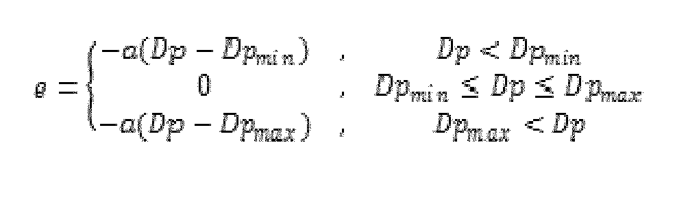
Hier wird unterhalb eines minimalen Differenzdruckwertes, das heißt eines unteren Grenzwertes Dpmin ein Fehlersignal e gemäß der Funktion e = -a(Dp - Dpmin) ausgegeben, wobei a ein konstanter Faktor ist. Zwischen den Grenzwerten Dpmin und Dpmax (oberer Grenzwert) wird auch hier ein konstantes Fehlersignal e mit dem Wert Null ausgegeben. Oberhalb des oberen Grenzwertes Dpmax wird ein Fehlersignal e nach der Funktion e = -a(Dp - Dpmax) ausgegeben. Das heißt unterhalb des unteren Grenzwertes Dpmin und oberhalb des oberen Grenzwertes Dpmax wird jeweils ein linear von dem Differenzdruck Dp abhängiges Fehlersignal e ausgegeben. Das Ausführungsbeispiel gemäß
Bei dem Ausführungsbeispiel gemäß
Anhand der 
Das heißt unterhalb eines unteren Grenzwertes Tr,min wird ein Fehlersignal e gemäß der Funktion e = a(Tr - Tr,min) ausgegeben, das heißt ein Fehlersignal e, welches linear abhängig von der Rücklauftemperatur Tr ist und mit fallender Rücklauftemperatur stärker abfällt, wobei das Fehlersignal negativ ist. Zwischen der unteren Grenze Tr,min und dem oberen Grenzwert Tr,max wird ein konstantes Fehlersignal e mit dem Wert Null ausgegeben. Oberhalb des oberen Grenzwertes Tr,max wird ein linear von der Temperatur Tr abhängiges Fehlersignal e nach der Gleichung e = a(Tr - Tr,max) ausgegeben. In den vorgenannten Gleichungen ist der Wert a ein konstanter Faktor. Oberhalb des Wertes Tr,max wird somit ein Fehlersignal e ausgegeben, welches linear mit der Temperatur Tr steigt.That is, below a lower limit value T r, min an error signal e according to the function e = a (Tr - T r, min ) is output, that is an error signal e, which is linearly dependent on the return temperature T r and stronger with falling return temperature drops, the error signal is negative. Between the lower limit T r, min and the upper limit value T r, max , a constant error signal e with the value zero is output. Above the upper limit value T r, max , an error signal e which depends linearly on the temperature T r is output according to the equation e = a (T r -Tr, max ). In the aforementioned equations, the value a is a constant factor. Above the value T r, max thus an error signal e is output, which increases linearly with the temperature T r .
Das Ausführungsbeispiel gemäß
Das Ausführungsbeispiel gemäß
Anhand der
In dem Beispiel gemäß
Gemäß dem vorangehenden Beispiel wird die Änderung des Kontrollsignals u gemäß der nachfolgenden Formel berechnet: 
Bei dieser Gleichung wird gleichzeitig eine Optimierung hinsichtlich des Energieverbrauches über das Signal DPpump, welches durch einen konstanten Wert angenähert werden kann, erreicht. Anstatt dieses Signals könnte eine Optimierung auch über eine Konstante in der folgenden Weise erfolgen: 
Dabei ist der Wert s ein konstanter Faktor, welcher in dem Fall positiv ist, dass die Summe der Fehlersignale e über die gesamte Anzahl N von Sensoren und/oder signalausgebenden Einheiten, wie Ventile, kleiner Null ist. Ein konstanter Wert -s wird in allen anderen Fällen ausgegeben.In this case, the value s is a constant factor, which is positive in the event that the sum of the error signals e over the total number N of sensors and / or signal-emitting units, such as valves, is less than zero. A constant value -s is output in all other cases.
Gemäß der vorangehend beschriebenen Ausführungsform wurden Differenzialausdrücke verwendet. Es ist jedoch zu verstehen, dass stattdessen auch diskrete Versionen Verwendung finden könnten, beispielsweise in Form folgender Gleichungen: 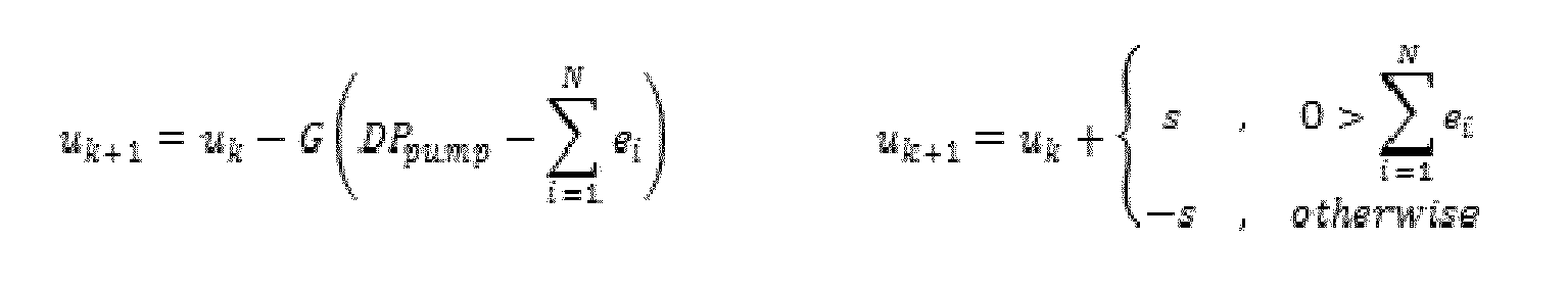
In diesen Gleichungen ist k ein zeitlicher Schritt. Die Faktoren G und s sind wiederum Konstanten.In these equations, k is a temporal step. The factors G and s are again constants.
Anstatt die Fehlersignale e mit Gewichtungsfaktoren w zu gewichten, können die Fehlersignale e gegebenenfalls in entsprechender Weise auch ohne Gewichtung direkt addiert werden.Instead of weighting the error signals e with weighting factors w, the error signals e may optionally be added directly in a corresponding manner without weighting.
Anstelle der Addition der Fehlersignale e kann auch eine Auswahl stattfinden, wie es anhand von
Der mit dem Bezugszeichen 36 in
- 22
- - Wärme- oder Kältequelle- Heat or cold source
- 44
- - Lastkreise- load circuits
- 66
- - Mischerpumpe- mixer pump
- 88th
- - Regulierventil- regulating valve
- 10, 1210, 12
- - Pumpenaggregat- Pump unit
- 1414
- - Versorgungsleitung- Supply line
- 1616
- - Differenzdrucksensor- Differential pressure sensor
- 1818
- - Verbraucher- Consumer
- 2020
- - Drucksensor- Pressure sensor
- 2222
- - Verbraucher- Consumer
- 2424
- - Temperatursensor- Temperature sensor
- 2626
- - Signalverarbeitungseinrichtung- Signal processing device
- 28, 3028, 30
- - Addierer- adder
- 3232
- - Integrierer- integrator
- 3434
- - Auswahleinrichtung- Selection device
- 3636
- - Teil der Regeleinrichtung- part of the control device
- ee
- - Fehlersignal- error signal
- xp x p
- - Ventilöffnungsgrad- Valve opening degree
- Dpdp
- - Differenzdruck- differential pressure
- TT
- - Temperaturdruck- temperature pressure
- DPpump DP pump
- - Änderung der Leistungsaufnahme- Change in power consumption
- GG
- - Verstärkungsfaktor- gain factor
- uu
- - Kontrollsignal- Control signal
Claims (19)
aus der erfassten Variable (Dp, p, T, xp) auf Grundlage einer abschnittsweise monotonen Funktion ein Fehlersignal (e) erzeugt wird, auf dessen Grundlage die Drehzahl (n) des Pumpenaggregates (10, 12) reguliert wird.Control method for a pump unit (10, 12) in a pneumatic or hydraulic system, wherein the speed (n) of the pump unit (10, 12) in response to at least one detected in the system variable (Dp, p, T, x p ) adjustable is, characterized in that
an error signal (e) is generated from the detected variable (Dp, p, T, xp ) on the basis of a partially monotonous function, on the basis of which the rotational speed (n) of the pump unit (10, 12) is regulated.
Priority Applications (5)
| Application Number | Priority Date | Filing Date | Title |
|---|---|---|---|
| EP14181144.8A EP2985536B1 (en) | 2014-08-15 | 2014-08-15 | Control method for a pump unit |
| DK14181144.8T DK2985536T3 (en) | 2014-08-15 | 2014-08-15 | Method for regulating a pump assembly |
| US14/826,631 US11085437B2 (en) | 2014-08-15 | 2015-08-14 | Control method |
| RU2015134323A RU2613474C2 (en) | 2014-08-15 | 2015-08-14 | Control method for pump unit |
| CN201510500928.0A CN105370554B (en) | 2014-08-15 | 2015-08-14 | Regulation and control method for pump assembly |
Applications Claiming Priority (1)
| Application Number | Priority Date | Filing Date | Title |
|---|---|---|---|
| EP14181144.8A EP2985536B1 (en) | 2014-08-15 | 2014-08-15 | Control method for a pump unit |
Publications (2)
| Publication Number | Publication Date |
|---|---|
| EP2985536A1 true EP2985536A1 (en) | 2016-02-17 |
| EP2985536B1 EP2985536B1 (en) | 2018-04-04 |
Family
ID=51357805
Family Applications (1)
| Application Number | Title | Priority Date | Filing Date |
|---|---|---|---|
| EP14181144.8A Active EP2985536B1 (en) | 2014-08-15 | 2014-08-15 | Control method for a pump unit |
Country Status (5)
| Country | Link |
|---|---|
| US (1) | US11085437B2 (en) |
| EP (1) | EP2985536B1 (en) |
| CN (1) | CN105370554B (en) |
| DK (1) | DK2985536T3 (en) |
| RU (1) | RU2613474C2 (en) |
Cited By (2)
| Publication number | Priority date | Publication date | Assignee | Title |
|---|---|---|---|---|
| US20150369494A1 (en) * | 2014-06-24 | 2015-12-24 | Grundfos Holding A/S | Method for limiting a supply flow in a heat transfer system |
| DE102017001722B4 (en) | 2017-02-23 | 2023-10-26 | Wilo Se | Method for setting the operation of a pump unit and arrangement of a pump unit and electronics for carrying out the method |
Families Citing this family (5)
| Publication number | Priority date | Publication date | Assignee | Title |
|---|---|---|---|---|
| US10920769B2 (en) | 2016-11-14 | 2021-02-16 | Fluid Handling Llc | Pump cloud-based management and control technique customized hydronic components |
| DE102017203960A1 (en) * | 2017-03-10 | 2018-09-13 | KSB SE & Co. KGaA | Method for operating a circulating pump and circulating pump for carrying out the method |
| CN108534210B (en) * | 2018-06-14 | 2023-12-01 | 济南金孚瑞供热工程技术有限公司 | Implementation method of stacked energy storage type heat pump heating system |
| WO2024088860A1 (en) * | 2022-10-26 | 2024-05-02 | Grundfos Holding A/S | Method and system for controlling a fluid pressure in a fluid system |
| WO2024170922A1 (en) * | 2023-02-16 | 2024-08-22 | Totalenergies Onetech | Method for control of a hydrocarbon production well |
Citations (4)
| Publication number | Priority date | Publication date | Assignee | Title |
|---|---|---|---|---|
| DE3315828A1 (en) | 1983-04-30 | 1984-10-31 | Licentia Patent-Verwaltungs-Gmbh, 6000 Frankfurt | Heating installation |
| CA2274782A1 (en) * | 1999-06-16 | 1999-11-07 | Larry O'keefe | Automatic variable demand control system for regulating the water supply in a high rise building |
| EP1323984A1 (en) * | 2001-12-24 | 2003-07-02 | Grundfos A/S | Method for controlling a variable speed circulation pump for heating system |
| DE102006049440A1 (en) * | 2005-10-17 | 2007-04-19 | I F M Electronic Gmbh | Method for determination of condition in particular of centrifugal or reciprocating and rotary pump, comprises use of parameters of pulsation of pressure and/or flow |
Family Cites Families (6)
| Publication number | Priority date | Publication date | Assignee | Title |
|---|---|---|---|---|
| SU1763723A1 (en) * | 1990-11-19 | 1992-09-23 | Рижский Краснознаменный Институт Инженеров Гражданской Авиации Им.Ленинского Комсомола | Method of controlling flow rate ratio of centrifugal pumps |
| US6993921B2 (en) * | 2004-03-04 | 2006-02-07 | Carrier Corporation | Multi-variable control of refrigerant systems |
| US7845913B2 (en) * | 2004-08-26 | 2010-12-07 | Pentair Water Pool And Spa, Inc. | Flow control |
| WO2006136202A1 (en) * | 2005-06-21 | 2006-12-28 | Itt Manufacturing Enterprises Inc. | Control system for a pump |
| JP5763329B2 (en) * | 2010-11-30 | 2015-08-12 | アルバック機工株式会社 | Pump device and control method thereof |
| US20150075148A1 (en) * | 2012-05-18 | 2015-03-19 | Kenpei Yamaji | Hydraulic control system |
-
2014
- 2014-08-15 EP EP14181144.8A patent/EP2985536B1/en active Active
- 2014-08-15 DK DK14181144.8T patent/DK2985536T3/en active
-
2015
- 2015-08-14 RU RU2015134323A patent/RU2613474C2/en active
- 2015-08-14 CN CN201510500928.0A patent/CN105370554B/en active Active
- 2015-08-14 US US14/826,631 patent/US11085437B2/en active Active
Patent Citations (4)
| Publication number | Priority date | Publication date | Assignee | Title |
|---|---|---|---|---|
| DE3315828A1 (en) | 1983-04-30 | 1984-10-31 | Licentia Patent-Verwaltungs-Gmbh, 6000 Frankfurt | Heating installation |
| CA2274782A1 (en) * | 1999-06-16 | 1999-11-07 | Larry O'keefe | Automatic variable demand control system for regulating the water supply in a high rise building |
| EP1323984A1 (en) * | 2001-12-24 | 2003-07-02 | Grundfos A/S | Method for controlling a variable speed circulation pump for heating system |
| DE102006049440A1 (en) * | 2005-10-17 | 2007-04-19 | I F M Electronic Gmbh | Method for determination of condition in particular of centrifugal or reciprocating and rotary pump, comprises use of parameters of pulsation of pressure and/or flow |
Cited By (3)
| Publication number | Priority date | Publication date | Assignee | Title |
|---|---|---|---|---|
| US20150369494A1 (en) * | 2014-06-24 | 2015-12-24 | Grundfos Holding A/S | Method for limiting a supply flow in a heat transfer system |
| US10184671B2 (en) * | 2014-06-24 | 2019-01-22 | Grundfos Holding A/S | Method for limiting a supply flow in a heat transfer system |
| DE102017001722B4 (en) | 2017-02-23 | 2023-10-26 | Wilo Se | Method for setting the operation of a pump unit and arrangement of a pump unit and electronics for carrying out the method |
Also Published As
| Publication number | Publication date |
|---|---|
| DK2985536T3 (en) | 2018-07-16 |
| US20160047372A1 (en) | 2016-02-18 |
| CN105370554A (en) | 2016-03-02 |
| US11085437B2 (en) | 2021-08-10 |
| CN105370554B (en) | 2017-12-26 |
| EP2985536B1 (en) | 2018-04-04 |
| RU2015134323A (en) | 2017-02-20 |
| RU2613474C2 (en) | 2017-03-16 |
Similar Documents
| Publication | Publication Date | Title |
|---|---|---|
| EP2985536B1 (en) | Control method for a pump unit | |
| EP1606556B1 (en) | Method for adjusting several parallel connected heat exchangers | |
| EP2960587B1 (en) | Method for limiting the supply flow rate in a heat transfer system | |
| EP2874039B1 (en) | Control method for a heat transfer system and heat transfer system | |
| EP2678563B1 (en) | Performance enhanced operation of a pump driven by an electric motor using positive-feedback | |
| DE69803577T2 (en) | ADAPTIVE CASCADED CONTROL ALGORITHM | |
| EP2913594B1 (en) | Method for operating a heating system with no buffer storage, in particular for guaranteeing safe and correct operation | |
| EP2187136A2 (en) | Method for operating a system for transporting thermal energy through a liquid medium | |
| EP3495056A1 (en) | Improved control of water conservancy of a cooling section | |
| DE102016219740A1 (en) | Control device for a DC-DC converter, DC-DC converter and method for controlling a DC-DC converter | |
| DE102017213650A1 (en) | Method for controlling a hydraulic system, control unit for a hydraulic system and hydraulic system | |
| DE102017001722A1 (en) | Method for setting the operation of a pump set and arrangement of a pump set and electronics for carrying out the method | |
| EP0594886B1 (en) | Method and controlling a heating system and device for carrying out the method | |
| EP0515639B1 (en) | Hydraulic system | |
| EP3026352A1 (en) | Method for hydraulically regulating several heating circuits on the distributor beam | |
| EP2304515A1 (en) | Control arrangement having a pressure limiting valve | |
| DE4006186C2 (en) | Method for controlling the speed of a pump driven by a speed-controlled electric motor | |
| DE102019206328A1 (en) | Process and control unit for controlling a heating circuit | |
| EP2288969B1 (en) | Control system of a plant having multi-stage model optimization | |
| EP3267039B1 (en) | System and method for controlling a pump station | |
| EP2947325B1 (en) | Pump control method | |
| EP1235131A2 (en) | Room temperature control | |
| EP3647899A1 (en) | Method for operating a valve, related electronic control unit and valve drive | |
| EP3168540A1 (en) | Method for carrying out an automated hydraulic balance, valve and heating system for same | |
| DE10254498C2 (en) | Method and temperature control device for humidity-dependent control of the internal temperature of a room |
Legal Events
| Date | Code | Title | Description |
|---|---|---|---|
| PUAI | Public reference made under article 153(3) epc to a published international application that has entered the european phase |
Free format text: ORIGINAL CODE: 0009012 |
|
| AK | Designated contracting states |
Kind code of ref document: A1 Designated state(s): AL AT BE BG CH CY CZ DE DK EE ES FI FR GB GR HR HU IE IS IT LI LT LU LV MC MK MT NL NO PL PT RO RS SE SI SK SM TR |
|
| AX | Request for extension of the european patent |
Extension state: BA ME |
|
| 17P | Request for examination filed |
Effective date: 20160816 |
|
| RBV | Designated contracting states (corrected) |
Designated state(s): AL AT BE BG CH CY CZ DE DK EE ES FI FR GB GR HR HU IE IS IT LI LT LU LV MC MK MT NL NO PL PT RO RS SE SI SK SM TR |
|
| REG | Reference to a national code |
Ref country code: DE Ref legal event code: R079 Ref document number: 502014007820 Country of ref document: DE Free format text: PREVIOUS MAIN CLASS: F24D0019100000 Ipc: F04B0049060000 |
|
| GRAP | Despatch of communication of intention to grant a patent |
Free format text: ORIGINAL CODE: EPIDOSNIGR1 |
|
| RIC1 | Information provided on ipc code assigned before grant |
Ipc: G05D 1/00 20060101ALI20170717BHEP Ipc: F04B 49/20 20060101ALI20170717BHEP Ipc: F04B 49/06 20060101AFI20170717BHEP Ipc: F04D 15/00 20060101ALI20170717BHEP Ipc: F24D 19/10 20060101ALI20170717BHEP |
|
| STAA | Information on the status of an ep patent application or granted ep patent |
Free format text: STATUS: GRANT OF PATENT IS INTENDED |
|
| INTG | Intention to grant announced |
Effective date: 20170824 |
|
| GRAJ | Information related to disapproval of communication of intention to grant by the applicant or resumption of examination proceedings by the epo deleted |
Free format text: ORIGINAL CODE: EPIDOSDIGR1 |
|
| STAA | Information on the status of an ep patent application or granted ep patent |
Free format text: STATUS: REQUEST FOR EXAMINATION WAS MADE |
|
| INTC | Intention to grant announced (deleted) | ||
| GRAR | Information related to intention to grant a patent recorded |
Free format text: ORIGINAL CODE: EPIDOSNIGR71 |
|
| GRAS | Grant fee paid |
Free format text: ORIGINAL CODE: EPIDOSNIGR3 |
|
| STAA | Information on the status of an ep patent application or granted ep patent |
Free format text: STATUS: GRANT OF PATENT IS INTENDED |
|
| GRAA | (expected) grant |
Free format text: ORIGINAL CODE: 0009210 |
|
| STAA | Information on the status of an ep patent application or granted ep patent |
Free format text: STATUS: THE PATENT HAS BEEN GRANTED |
|
| AK | Designated contracting states |
Kind code of ref document: B1 Designated state(s): AL AT BE BG CH CY CZ DE DK EE ES FI FR GB GR HR HU IE IS IT LI LT LU LV MC MK MT NL NO PL PT RO RS SE SI SK SM TR |
|
| INTG | Intention to grant announced |
Effective date: 20180223 |
|
| REG | Reference to a national code |
Ref country code: GB Ref legal event code: FG4D Free format text: NOT ENGLISH |
|
| REG | Reference to a national code |
Ref country code: CH Ref legal event code: EP |
|
| REG | Reference to a national code |
Ref country code: AT Ref legal event code: REF Ref document number: 985895 Country of ref document: AT Kind code of ref document: T Effective date: 20180415 |
|
| REG | Reference to a national code |
Ref country code: DE Ref legal event code: R096 Ref document number: 502014007820 Country of ref document: DE |
|
| REG | Reference to a national code |
Ref country code: IE Ref legal event code: FG4D Free format text: LANGUAGE OF EP DOCUMENT: GERMAN |
|
| REG | Reference to a national code |
Ref country code: CH Ref legal event code: NV Representative=s name: ISLER AND PEDRAZZINI AG, CH |
|
| REG | Reference to a national code |
Ref country code: DK Ref legal event code: T3 Effective date: 20180709 |
|
| REG | Reference to a national code |
Ref country code: NL Ref legal event code: MP Effective date: 20180404 |
|
| REG | Reference to a national code |
Ref country code: FR Ref legal event code: PLFP Year of fee payment: 5 |
|
| REG | Reference to a national code |
Ref country code: LT Ref legal event code: MG4D |
|
| PG25 | Lapsed in a contracting state [announced via postgrant information from national office to epo] |
Ref country code: NL Free format text: LAPSE BECAUSE OF FAILURE TO SUBMIT A TRANSLATION OF THE DESCRIPTION OR TO PAY THE FEE WITHIN THE PRESCRIBED TIME-LIMIT Effective date: 20180404 |
|
| PG25 | Lapsed in a contracting state [announced via postgrant information from national office to epo] |
Ref country code: NO Free format text: LAPSE BECAUSE OF FAILURE TO SUBMIT A TRANSLATION OF THE DESCRIPTION OR TO PAY THE FEE WITHIN THE PRESCRIBED TIME-LIMIT Effective date: 20180704 Ref country code: FI Free format text: LAPSE BECAUSE OF FAILURE TO SUBMIT A TRANSLATION OF THE DESCRIPTION OR TO PAY THE FEE WITHIN THE PRESCRIBED TIME-LIMIT Effective date: 20180404 Ref country code: PL Free format text: LAPSE BECAUSE OF FAILURE TO SUBMIT A TRANSLATION OF THE DESCRIPTION OR TO PAY THE FEE WITHIN THE PRESCRIBED TIME-LIMIT Effective date: 20180404 Ref country code: LT Free format text: LAPSE BECAUSE OF FAILURE TO SUBMIT A TRANSLATION OF THE DESCRIPTION OR TO PAY THE FEE WITHIN THE PRESCRIBED TIME-LIMIT Effective date: 20180404 Ref country code: ES Free format text: LAPSE BECAUSE OF FAILURE TO SUBMIT A TRANSLATION OF THE DESCRIPTION OR TO PAY THE FEE WITHIN THE PRESCRIBED TIME-LIMIT Effective date: 20180404 Ref country code: AL Free format text: LAPSE BECAUSE OF FAILURE TO SUBMIT A TRANSLATION OF THE DESCRIPTION OR TO PAY THE FEE WITHIN THE PRESCRIBED TIME-LIMIT Effective date: 20180404 Ref country code: SE Free format text: LAPSE BECAUSE OF FAILURE TO SUBMIT A TRANSLATION OF THE DESCRIPTION OR TO PAY THE FEE WITHIN THE PRESCRIBED TIME-LIMIT Effective date: 20180404 Ref country code: BG Free format text: LAPSE BECAUSE OF FAILURE TO SUBMIT A TRANSLATION OF THE DESCRIPTION OR TO PAY THE FEE WITHIN THE PRESCRIBED TIME-LIMIT Effective date: 20180704 |
|
| PG25 | Lapsed in a contracting state [announced via postgrant information from national office to epo] |
Ref country code: LV Free format text: LAPSE BECAUSE OF FAILURE TO SUBMIT A TRANSLATION OF THE DESCRIPTION OR TO PAY THE FEE WITHIN THE PRESCRIBED TIME-LIMIT Effective date: 20180404 Ref country code: RS Free format text: LAPSE BECAUSE OF FAILURE TO SUBMIT A TRANSLATION OF THE DESCRIPTION OR TO PAY THE FEE WITHIN THE PRESCRIBED TIME-LIMIT Effective date: 20180404 Ref country code: GR Free format text: LAPSE BECAUSE OF FAILURE TO SUBMIT A TRANSLATION OF THE DESCRIPTION OR TO PAY THE FEE WITHIN THE PRESCRIBED TIME-LIMIT Effective date: 20180705 Ref country code: HR Free format text: LAPSE BECAUSE OF FAILURE TO SUBMIT A TRANSLATION OF THE DESCRIPTION OR TO PAY THE FEE WITHIN THE PRESCRIBED TIME-LIMIT Effective date: 20180404 |
|
| PG25 | Lapsed in a contracting state [announced via postgrant information from national office to epo] |
Ref country code: PT Free format text: LAPSE BECAUSE OF FAILURE TO SUBMIT A TRANSLATION OF THE DESCRIPTION OR TO PAY THE FEE WITHIN THE PRESCRIBED TIME-LIMIT Effective date: 20180806 |
|
| REG | Reference to a national code |
Ref country code: DE Ref legal event code: R097 Ref document number: 502014007820 Country of ref document: DE |
|
| PG25 | Lapsed in a contracting state [announced via postgrant information from national office to epo] |
Ref country code: EE Free format text: LAPSE BECAUSE OF FAILURE TO SUBMIT A TRANSLATION OF THE DESCRIPTION OR TO PAY THE FEE WITHIN THE PRESCRIBED TIME-LIMIT Effective date: 20180404 Ref country code: SK Free format text: LAPSE BECAUSE OF FAILURE TO SUBMIT A TRANSLATION OF THE DESCRIPTION OR TO PAY THE FEE WITHIN THE PRESCRIBED TIME-LIMIT Effective date: 20180404 Ref country code: RO Free format text: LAPSE BECAUSE OF FAILURE TO SUBMIT A TRANSLATION OF THE DESCRIPTION OR TO PAY THE FEE WITHIN THE PRESCRIBED TIME-LIMIT Effective date: 20180404 Ref country code: CZ Free format text: LAPSE BECAUSE OF FAILURE TO SUBMIT A TRANSLATION OF THE DESCRIPTION OR TO PAY THE FEE WITHIN THE PRESCRIBED TIME-LIMIT Effective date: 20180404 |
|
| PLBE | No opposition filed within time limit |
Free format text: ORIGINAL CODE: 0009261 |
|
| STAA | Information on the status of an ep patent application or granted ep patent |
Free format text: STATUS: NO OPPOSITION FILED WITHIN TIME LIMIT |
|
| PG25 | Lapsed in a contracting state [announced via postgrant information from national office to epo] |
Ref country code: SM Free format text: LAPSE BECAUSE OF FAILURE TO SUBMIT A TRANSLATION OF THE DESCRIPTION OR TO PAY THE FEE WITHIN THE PRESCRIBED TIME-LIMIT Effective date: 20180404 |
|
| 26N | No opposition filed |
Effective date: 20190107 |
|
| PG25 | Lapsed in a contracting state [announced via postgrant information from national office to epo] |
Ref country code: MC Free format text: LAPSE BECAUSE OF FAILURE TO SUBMIT A TRANSLATION OF THE DESCRIPTION OR TO PAY THE FEE WITHIN THE PRESCRIBED TIME-LIMIT Effective date: 20180404 |
|
| PG25 | Lapsed in a contracting state [announced via postgrant information from national office to epo] |
Ref country code: LU Free format text: LAPSE BECAUSE OF NON-PAYMENT OF DUE FEES Effective date: 20180815 |
|
| REG | Reference to a national code |
Ref country code: BE Ref legal event code: MM Effective date: 20180831 |
|
| REG | Reference to a national code |
Ref country code: IE Ref legal event code: MM4A |
|
| PG25 | Lapsed in a contracting state [announced via postgrant information from national office to epo] |
Ref country code: SI Free format text: LAPSE BECAUSE OF FAILURE TO SUBMIT A TRANSLATION OF THE DESCRIPTION OR TO PAY THE FEE WITHIN THE PRESCRIBED TIME-LIMIT Effective date: 20180404 |
|
| PG25 | Lapsed in a contracting state [announced via postgrant information from national office to epo] |
Ref country code: IE Free format text: LAPSE BECAUSE OF NON-PAYMENT OF DUE FEES Effective date: 20180815 |
|
| PG25 | Lapsed in a contracting state [announced via postgrant information from national office to epo] |
Ref country code: BE Free format text: LAPSE BECAUSE OF NON-PAYMENT OF DUE FEES Effective date: 20180831 |
|
| PG25 | Lapsed in a contracting state [announced via postgrant information from national office to epo] |
Ref country code: MT Free format text: LAPSE BECAUSE OF FAILURE TO SUBMIT A TRANSLATION OF THE DESCRIPTION OR TO PAY THE FEE WITHIN THE PRESCRIBED TIME-LIMIT Effective date: 20180404 |
|
| PG25 | Lapsed in a contracting state [announced via postgrant information from national office to epo] |
Ref country code: TR Free format text: LAPSE BECAUSE OF FAILURE TO SUBMIT A TRANSLATION OF THE DESCRIPTION OR TO PAY THE FEE WITHIN THE PRESCRIBED TIME-LIMIT Effective date: 20180404 |
|
| PG25 | Lapsed in a contracting state [announced via postgrant information from national office to epo] |
Ref country code: HU Free format text: LAPSE BECAUSE OF FAILURE TO SUBMIT A TRANSLATION OF THE DESCRIPTION OR TO PAY THE FEE WITHIN THE PRESCRIBED TIME-LIMIT; INVALID AB INITIO Effective date: 20140815 Ref country code: CY Free format text: LAPSE BECAUSE OF FAILURE TO SUBMIT A TRANSLATION OF THE DESCRIPTION OR TO PAY THE FEE WITHIN THE PRESCRIBED TIME-LIMIT Effective date: 20180404 Ref country code: MK Free format text: LAPSE BECAUSE OF NON-PAYMENT OF DUE FEES Effective date: 20180404 |
|
| PG25 | Lapsed in a contracting state [announced via postgrant information from national office to epo] |
Ref country code: IS Free format text: LAPSE BECAUSE OF FAILURE TO SUBMIT A TRANSLATION OF THE DESCRIPTION OR TO PAY THE FEE WITHIN THE PRESCRIBED TIME-LIMIT Effective date: 20180804 |
|
| REG | Reference to a national code |
Ref country code: AT Ref legal event code: MM01 Ref document number: 985895 Country of ref document: AT Kind code of ref document: T Effective date: 20190815 |
|
| PG25 | Lapsed in a contracting state [announced via postgrant information from national office to epo] |
Ref country code: AT Free format text: LAPSE BECAUSE OF NON-PAYMENT OF DUE FEES Effective date: 20190815 |
|
| REG | Reference to a national code |
Ref country code: DE Ref legal event code: R082 Ref document number: 502014007820 Country of ref document: DE |
|
| PGFP | Annual fee paid to national office [announced via postgrant information from national office to epo] |
Ref country code: IT Payment date: 20220825 Year of fee payment: 9 Ref country code: GB Payment date: 20220822 Year of fee payment: 9 Ref country code: DK Payment date: 20220824 Year of fee payment: 9 Ref country code: DE Payment date: 20220819 Year of fee payment: 9 |
|
| PGFP | Annual fee paid to national office [announced via postgrant information from national office to epo] |
Ref country code: FR Payment date: 20220823 Year of fee payment: 9 |
|
| PGFP | Annual fee paid to national office [announced via postgrant information from national office to epo] |
Ref country code: CH Payment date: 20220824 Year of fee payment: 9 |
|
| REG | Reference to a national code |
Ref country code: DE Ref legal event code: R119 Ref document number: 502014007820 Country of ref document: DE |
|
| REG | Reference to a national code |
Ref country code: DK Ref legal event code: EBP Effective date: 20230831 |
|
| REG | Reference to a national code |
Ref country code: CH Ref legal event code: PL |
|
| GBPC | Gb: european patent ceased through non-payment of renewal fee |
Effective date: 20230815 |
|
| PG25 | Lapsed in a contracting state [announced via postgrant information from national office to epo] |
Ref country code: CH Free format text: LAPSE BECAUSE OF NON-PAYMENT OF DUE FEES Effective date: 20230831 |
|
| PG25 | Lapsed in a contracting state [announced via postgrant information from national office to epo] |
Ref country code: GB Free format text: LAPSE BECAUSE OF NON-PAYMENT OF DUE FEES Effective date: 20230815 |
|
| PG25 | Lapsed in a contracting state [announced via postgrant information from national office to epo] |
Ref country code: DK Free format text: LAPSE BECAUSE OF NON-PAYMENT OF DUE FEES Effective date: 20230831 |
|
| PG25 | Lapsed in a contracting state [announced via postgrant information from national office to epo] |
Ref country code: IT Free format text: LAPSE BECAUSE OF NON-PAYMENT OF DUE FEES Effective date: 20230815 Ref country code: GB Free format text: LAPSE BECAUSE OF NON-PAYMENT OF DUE FEES Effective date: 20230815 Ref country code: FR Free format text: LAPSE BECAUSE OF NON-PAYMENT OF DUE FEES Effective date: 20230831 Ref country code: DK Free format text: LAPSE BECAUSE OF NON-PAYMENT OF DUE FEES Effective date: 20230831 Ref country code: DE Free format text: LAPSE BECAUSE OF NON-PAYMENT OF DUE FEES Effective date: 20240301 |