EP2985484A2 - Electromagnetic clutch - Google Patents
Electromagnetic clutch Download PDFInfo
- Publication number
- EP2985484A2 EP2985484A2 EP15002199.6A EP15002199A EP2985484A2 EP 2985484 A2 EP2985484 A2 EP 2985484A2 EP 15002199 A EP15002199 A EP 15002199A EP 2985484 A2 EP2985484 A2 EP 2985484A2
- Authority
- EP
- European Patent Office
- Prior art keywords
- rotor
- end surface
- side end
- blocking portion
- armature plate
- Prior art date
- Legal status (The legal status is an assumption and is not a legal conclusion. Google has not performed a legal analysis and makes no representation as to the accuracy of the status listed.)
- Granted
Links
- 230000000903 blocking effect Effects 0.000 claims abstract description 90
- 230000005284 excitation Effects 0.000 claims abstract description 44
- 230000002093 peripheral effect Effects 0.000 claims description 21
- 239000000696 magnetic material Substances 0.000 claims description 13
- 238000000926 separation method Methods 0.000 claims description 5
- 239000002184 metal Substances 0.000 description 13
- 229910052751 metal Inorganic materials 0.000 description 13
- 230000003068 static effect Effects 0.000 description 13
- 230000005540 biological transmission Effects 0.000 description 12
- 230000003247 decreasing effect Effects 0.000 description 8
- 238000012360 testing method Methods 0.000 description 6
- 150000002739 metals Chemical class 0.000 description 5
- 230000005489 elastic deformation Effects 0.000 description 4
- 230000004907 flux Effects 0.000 description 3
- 239000000463 material Substances 0.000 description 3
- 239000011347 resin Substances 0.000 description 3
- 229920005989 resin Polymers 0.000 description 3
- 230000008859 change Effects 0.000 description 2
- 230000008878 coupling Effects 0.000 description 2
- 238000010168 coupling process Methods 0.000 description 2
- 238000005859 coupling reaction Methods 0.000 description 2
- 238000010586 diagram Methods 0.000 description 2
- 239000007769 metal material Substances 0.000 description 2
- 230000004048 modification Effects 0.000 description 2
- 238000012986 modification Methods 0.000 description 2
- 230000002459 sustained effect Effects 0.000 description 2
- 229920006231 aramid fiber Polymers 0.000 description 1
- 239000011230 binding agent Substances 0.000 description 1
- 230000015572 biosynthetic process Effects 0.000 description 1
- 125000000484 butyl group Chemical group [H]C([*])([H])C([H])([H])C([H])([H])C([H])([H])[H] 0.000 description 1
- 238000013461 design Methods 0.000 description 1
- 230000000694 effects Effects 0.000 description 1
- 238000011156 evaluation Methods 0.000 description 1
- 239000000835 fiber Substances 0.000 description 1
- 239000002657 fibrous material Substances 0.000 description 1
- 239000000945 filler Substances 0.000 description 1
- 239000012784 inorganic fiber Substances 0.000 description 1
- 238000004519 manufacturing process Methods 0.000 description 1
- 238000000034 method Methods 0.000 description 1
- 229910052755 nonmetal Inorganic materials 0.000 description 1
- 239000005011 phenolic resin Substances 0.000 description 1
- 230000008569 process Effects 0.000 description 1
- 230000009467 reduction Effects 0.000 description 1
- 229920003051 synthetic elastomer Polymers 0.000 description 1
- 239000005061 synthetic rubber Substances 0.000 description 1
- 229920001187 thermosetting polymer Polymers 0.000 description 1
Images


Classifications
-
- F—MECHANICAL ENGINEERING; LIGHTING; HEATING; WEAPONS; BLASTING
- F16—ENGINEERING ELEMENTS AND UNITS; GENERAL MEASURES FOR PRODUCING AND MAINTAINING EFFECTIVE FUNCTIONING OF MACHINES OR INSTALLATIONS; THERMAL INSULATION IN GENERAL
- F16D—COUPLINGS FOR TRANSMITTING ROTATION; CLUTCHES; BRAKES
- F16D27/00—Magnetically- or electrically- actuated clutches; Control or electric circuits therefor
- F16D27/10—Magnetically- or electrically- actuated clutches; Control or electric circuits therefor with an electromagnet not rotating with a clutching member, i.e. without collecting rings
- F16D27/108—Magnetically- or electrically- actuated clutches; Control or electric circuits therefor with an electromagnet not rotating with a clutching member, i.e. without collecting rings with axially movable clutching members
- F16D27/112—Magnetically- or electrically- actuated clutches; Control or electric circuits therefor with an electromagnet not rotating with a clutching member, i.e. without collecting rings with axially movable clutching members with flat friction surfaces, e.g. discs
-
- F—MECHANICAL ENGINEERING; LIGHTING; HEATING; WEAPONS; BLASTING
- F16—ENGINEERING ELEMENTS AND UNITS; GENERAL MEASURES FOR PRODUCING AND MAINTAINING EFFECTIVE FUNCTIONING OF MACHINES OR INSTALLATIONS; THERMAL INSULATION IN GENERAL
- F16D—COUPLINGS FOR TRANSMITTING ROTATION; CLUTCHES; BRAKES
- F16D27/00—Magnetically- or electrically- actuated clutches; Control or electric circuits therefor
- F16D2027/008—Details relating to the magnetic circuit, or to the shape of the clutch parts to achieve a certain magnetic path
Definitions
- the present invention relates to an electromagnetic clutch used for connecting and disconnecting power transmitting from a power source to a compressor and, in particular, to an electromagnetic clutch in which a friction member is provided on a side end surface of a rotor onto which an armature plate comes in contact.
- a general electromagnetic clutch used in a compressor of a vehicular air conditioner includes a rotor 4 that is formed of a magnetic material, is fitted onto an outer periphery of a cylindrical portion 16 through a bearing 14 to be rotatable in which a driving shaft 20 of a compressor 2 is journaled, and is rotated by receiving a rotational force from a rotation driving source; an armature plate 5 that is formed of a magnetic material, is connected to the driving shaft 20 to be relatively non-rotatable, and is disposed to face a side end surface of the rotor 4 across a slight gap; an excitation coil 3 that is accommodated in an inside of the rotor 4, forms a magnetic circuit through the rotor 4 and the armature plate 5 by being energized, and generates an attracting force that electromagnetically attracts the armature plate 5 onto the rotor 4; an outer magnetic blocking portion 21 provided on the side end surface of the rotor 4, that is configured with an annular shape
- a temperature fuse 15 which blocks electric connection to the excitation coil 3 when exceeding a predetermined temperature is provided on the excitation coil 3 side from the side end surface of the rotor 4. If the compressor 2 becomes unrotatable for some reason, slip occurs between the rotor 4 that is rotated by receiving the rotational driving force from the driving source and the armature plate 5 that is connected to the driving shaft 20 of the compressor 2 that is unrotatable.
- the temperature fuse 15 is fused by friction heat caused by the slip and a connection of the clutch is cut (electromagnetic attracting force that attracts the armature plate 5 onto the rotor 4 is removed) by blocking electric connection to the excitation coil 3.
- an annular groove 24 is formed on the side end surface of the rotor 4 facing the armature plate 5 so as to include the outer magnetic blocking portion 21, and a ring-shaped friction member 27 formed of a non-magnetic material such as thermosetting resin is mounted on the annular groove 24 in a state of being slightly protruded from the side end surface 4b of the rotor 4.
- the friction member 27 is disposed to cover the outer magnetic blocking portion 21 for ensuring a magnetic path and is slightly protruded from the side end surface of the rotor 4. Since the friction member 27 and the armature plate 5 have an elasticity in themselves, when the armature plate 5 is attracted to the rotor 4, the armature plate 5 comes into contact not only with the friction member 27 but also with the side end surface 4b of the rotor 4 in a region close to an inner periphery than the friction member 27. As described above, when the rotor 4 and the armature plate 5 are engaged, both of the friction member 27 and the inward region of the side end surface than the friction member 27 come contact with the armature plate 5 ,thereby performing stable transmission of torque.
- the invention is made in view of the above circumstances and a main object of the invention is to provide an electromagnetic clutch in which a concern of sticking between a rotor and an armature plate is avoided and a temperature fuse can be reliably fused even if slip occurs between the rotor and the armature plate.
- an electromagnetic clutch characterized by including: a rotor that is formed of a magnetic material and is rotated by receiving a rotational force from a rotation driving source; an armature plate that is formed of the magnetic material, is connected to a driving shaft of a compressor to be relatively non-rotatable, and is disposed to face a side end surface of the rotor across a slight gap; an excitation coil that is accommodated in the inside of the rotor, forms a magnetic circuit through the rotor and the armature plate by being energized, and generates an attracting force magnetically attracting the armature plate onto the rotor; a temperature fuse that is disposed on the excitation coil side further than the side end surface of the rotor and blocks the electric connection to the excitation coil when exceeding a predetermined temperature; an outer magnetic blocking portion provided on the side end surface of the rotor, which is configured with an annular shape centered on the driving shaft or a plurality of arc shapes disposed on a
- the friction member is disposed in the annular groove formed so as to include the inner magnetic blocking portion of the side end surface of the rotor so as to protrude from the side end surface of the rotor.
- an annular groove which includes the outer magnetic blocking portion and narrows a width of a magnetic path (a width of the pole in a radial direction) at the outside of the outer magnetic blocking portion so as to dispose the magnetic path radially outward, is formed on the side end surface of the rotor.
- the pole of the outside of the annular groove including the outer magnetic blocking portion is configured in a position further from a rotational center of Lhe rotor 4 and it is possible to improve transmission of a torque from the rotor to the armature plate.
- the friction member protruding from the side end surface of the rotor may be further disposed in the annular groove formed to include the outer magnetic blocking portion.
- the armature plate comes into contact with the friction member before the armature plate comes into contact with the rotor when being attracted, even in the vicinity of the outer peripheral edge of the rotor and the armature plate.
- the armature plate comes into contact with the friction member before the armature plate comes into contact with the rotor when being attracted, even in the vicinity of the outer peripheral edge of the rotor and the armature plate.
- the poles configure a first pole, a second pole, a third pole, and a fourth pole from the outside in the radial direction
- the third pole has a width in the radial direction of 60% or more of a width of the second pole in the radial direction.
- Disposing the friction member so as to include the inner magnetic blocking portion there is a concern that a magnetic path may be excessively narrowed on both sides of the inner magnetic blocking portion in the radial direction.
- it is possible to ensure the attracting force by making the width of the third pole in the radial direction be 60% or more of the width of the second pole in the same direction without increasing a magnetic resistance.
- the side end surface of the rotor may be formed in a center concave shape such that a separation distance from the armature plate is reduced toward the outside in the radial direction during electric disconnection to the excitation coil.
- a side end surface of the armature plate facing the side end surface of the rotor may be formed in a center concave shape such that a separation distance from the side end surface of the rotor is reduced toward the outside in the radial direction during electric disconnection to the excitation coil.
- the outer periphery side further than the friction member can come into contact with the armature plate from an initial use and the transmission of a torque by the friction can be stably ensured while avoiding a concern of sticking by slip between metals (slide contact between the rotor and the armature plate) when the compressor becomes unable to rotate.
- both the metal surface on the outer periphery side of the side end surface and the friction member on the inner periphery side come into contact with the armature plate from the initial use.
- a center concave depth of the side end surface of the rotor or the side end surface of the armature plate may be formed such that an inner peripheral edge of the side end surface is lower than an outer peripheral edge of the side end surface by 30 ⁇ m to 60 ⁇ m. Further, a protrusion amount of the friction member from the side end surface of the rotor is 10 ⁇ m to 50 ⁇ m.
- the annular groove is provided so as to include the inner magnetic blocking portion.
- formation of the poles is not inhibited on the outside and the inside of the magnetic blocking portion in the radial direction by the annular groove.
- the friction member provided in the position of the inner magnetic blocking portion it helps to transmit the torque during normal operation and makes it possible to avoid a concern of sticking between similar types of metals even if slip occurs between the rotor and the armature plate for some reason, since the slip at the region close to the inside where the peripheral speed is rather slow is made between the rotor and the armature plate through the friction member.
- the annular groove including the outer magnetic blocking portion and narrowing the width of the magnetic path (width of pole in the radial direction) at the outside of the outer magnetic blocking portion so as to dispose the magnetic path radially outward is formed on the side end surface of the rotor.
- the pole on the outside of the annular groove is configured in the position further from the rotational center of the rotor and it is possible to improve the transmission of a torque from the rotor to the armature plate.
- the friction member is also provided in the annular groove on the outside of the rotor.
- the friction member is also provided in the annular groove on the outside of the rotor.
- the magnetic path of the pole formed between the intermediate magnetic blocking portion and the inner magnetic blocking portion is narrowed by providing the annular groove for mounting the friction member so as to include the inner magnetic blocking portion.
- a significant increase in the magnetic resistance is not caused and it is possible to ensure required sufficient attracting force regardless of mounting of the friction member by setting the width of the pole to be 60% or more of the width of the magnetic path of the pole formed between the outer magnetic blocking portion and the intermediate magnetic blocking portion.
- the side end surface of the rotor is formed such that the distance from the armature plate during the electric disconnection of the excitation coil is decreased toward the outside in the radial direction or the side end surface of the armature plate facing the side end surface of the rotor is formed such that the distance from the side end surface of the rotor during the electric disconnection of the excitation coil is decreased toward the outside in the radial direction.
- both the metal surface on the outer periphery side of the side end surface and the friction member on inner periphery side come into contact with the armature plate from the initial use.
- the electromagnetic clutch 1 can intermittently supply a rotational driving force from a power source such as an engine or a motor to a compressor 2 that is a driven apparatus.
- the electromagnetic clutch 1 includes a rotor 4 that is supported to be rotatable centered on a driving shaft 20 of the compressor 2, an armature plate 5 that faces the rotor 4 in an axial direction, a hub 6 that is fixed to the driving shaft 20 of the compressor 2 and rotates together with the driving shaft 20, an outer plate 7 that is connected to the armature plate 5, an inner plate 8 that is connected to the hub 6, and an elastic member 10 that is interposed between the outer plate 7 and the inner plate 8.
- the rotor 4 is formed in an annular shape by a magnetic material, as illustrated in Figs. 2A to 2C , is formed of grooves 4a for mounting a coupling belt for coupling the driving source to an outer periphery thereof, is provided with a bearing 14 on an inner periphery, and is fitted onto an outer periphery of a cylindrical portion 16 through the bearing 14 to be rotatable in which the driving shaft 20 protruding from a housing 2a of the compressor 2 is jounaled.
- a side end surface 4b of the rotor 4 that is opposite to a body of the compressor 2 is formed in a planar shape that is substantially perpendicular to an axis of the rotor 4, and configures a friction surface facing the armature plate 5 described below.
- the armature plate 5 is formed in a disk shape by a magnetic material, is fixed to the outer plate 7 described below, and has a side end surface 5a facing the side end surface 4b of the rotor 4 across a slight gap.
- the side end surface 5a is configured of a friction surface that is formed in a planar shape that is substantially perpendicular to the axis of the rotor 4 and faces the rotor 4.
- An excitation coil 3 is accommodated in a coil groove 11a of a stator housing 11 and is wound around a bobbin 12 fixed by a resin mold 11b.
- the stator housing 11 in which the excitation coil 3 is accommodated is fixed to the housing 2a of the compressor 2 through a mounting plate 13.
- the rotor 4 is provided with an annular space 41 which is opened to the housing of the compressor 2.
- the rotor 4 is provided so as to cover the excitation coil 3 from the armature plate side and rotates along the excitation coil without coming into contact with the excitation coil 3.
- a temperature fuse 15 which is fused when exceeding a predetermined temperature and blocks the electric connection to the excitation coil 3, is provided on the excitation coil side further than the side end surface 4b of the rotor 4.
- the temperature fuses 15 are fixed to the vicinity of an opening end of the coil groove 11a of the stator housing 11 by the resin mold 11b.
- a plurality of temperature fuses 15 may be provided along the excitation coil 3 and are connected to the excitation coil 3 in series, and the electric connection to the excitation coil 3 is blocked if one of the temperature fuses 15 is fused.
- an outer magnetic blocking portion 21 and an inner magnetic blocking portion 22, which make a passage of magnetic flux generated by energizing the excitation coil 3 go around by blocking the passage thereof, are intermittently formed in a circumferential direction along virtual circles of which distances from the axis (driving shaft 20) of the rotor 4 are different.
- the outer magnetic blocking portions 21 are configured by forming four arc-shaped long holes on the virtual circle centered on the axis of the rotor 4 at regular intervals.
- the inner magnetic blocking portions 22 are configured by forming six arc-shaped long holes on the virtual circle of which a diameter is smaller than that of the virtual circle of the outer magnetic blocking portions 21 centered on the axis of the rotor 4 at regular intervals.
- an intermediate magnetic blocking portion 23 for making the magnetic flux generated by energizing the excitation coil 3 go aound is provided in a position shifted in the radial direction from the magnetic blocking portions 21 and 22 formed on the side end surface 4b of the rotor 4.
- the intermediate magnetic blocking portion 23 is configured by a ring-shaped member 53 made of a non-magnetic metal and the armature plate 5 is formed by one disk-shaped plate having no hole by sticking the ring-shaped member 53 between an outer annular plate 51 and an inner annul ar plate 52 made of a magnetic metal.
- a first pole A is formed in a portion on the outside of the outer magnetic blocking portion 21 in the radial direction
- a second pole B is formed in a portion between the outer magnetic blocking portion 21 and the intermediate magnetic blocking portion 23
- a third pole C is formed between the intermediate magnetic blocking portion 23 and the inner magnetic blocking portion 22
- a fourth pole D is formed in a portion of the inside of the inner magnetic blocking portion 22 in the radial direction
- a magnetic circuit in which magnetic flux passes through a periphery of the excitation coil 3 via the first pole A, the second pole B, the third pole C, and the fourth pole D is formed by enegizing the excitation coil 3, and thereby a attracting force that attracts the armature plate 5 to the rotor 4 is generated.
- the outer plate 7 is configured to have a cylindrical holding portion 7a extending in the axial direction for holding the elastic member 10 and a flange 7b extending from an end portion of the holding portion 7a on the armature plate side along a surface of the armature plate 5, and is fixed to the armature plate 5 by rivets 17 mounted on the flange 7b.
- the hub 6 is fixed to the end portion of the driving shaft 20 by a bolt 18 and the inner plate 8 is fixed to a flange 6b extending in the radial direction from a body 6a of the hub 6 fixed to the driving shaft 20 by rivets 19.
- the inner plate 8 is a body separated from the hub 6, has a substantially disk shape, and is configured to have a base portion 8a that is put on the flange 6b of the hub 6 and is fixed by the rivets 19, and a holding portion 8b that is erected from an outer peripheral edge of the base portion 8a along the axial direction in a substantially cylindrical shape and holds the clastic member 10.
- the elastic member 10 is interposed in an annular space 9 formed between the holding portion 7a of the outer plate 7 and the holding portion 8b of the inner plate 8, the elastic member 10 is adhered to both the outer plate 7 and the inner plate 8, and thereby the outer plate 7 and the inner plate 8 are connected through the elastic member 10.
- the elastic member 10 is configured of an annular-shaped synthetic rubber (NBR, chlorinated butyl, and the like) provided around an entire periphery of the holding portion 7a of the outer plate 7 and the holding portion 8b of the inner plate 8, a torque fluctuation in a rotation direction is absorbed by twisting, and thus damage of the driving shaft 20 and the like resulting from the torque fluctuation is prevented.
- NBR annular-shaped synthetic rubber
- deformation due to the armature plate 5 attracted to the rotor 4 is allowed by the elasticity of the elastic member 10.
- the armature plate 5 is attracted onto the side end surface side of the rotor 4 by the elastic deformation of the elastic member 10 and if the excitation coil 3 is deeneqized, the armature plate 5 is separated from the side end surface of the rotor 4 by a restoring force of the elastic member 10.
- annular groove 25 formed in a circular shape is formed on the side end surface 4b of the rotor 4 centered on the axis of the rotor 4 so as to include the inner magnetic blocking portion 22, and a friction member 26 is disposed in the annular groove 25.
- the friction member 26 is configured ot a non-magnetic material, is formed in a circular shape and in a planar shape having a diameter according to a size of the annular groove 25, is accommodated and fixed in the annular groove 25 so that the surface facing the armature plate 5 slightly protrudes (in this example, it becomes 0.010 mm to 0.050 mm) from the side end surface 4b of the rotor 4.
- the friction member 26 is provided to obtain functions for a predetermined elastic deformation, reduction of impact noise, torque transmission, wear resistance, and the like.
- the friction member 26 can be formed by using a material in which a base material is formed of a fiber material such as aramid fiber, nonferrous metal fiber, and inorganic fiber, in which a filler, friction-characteristic improving material, and the like are mixed, and which is combined with a binder such as phenol resin.
- the attracting force can be controlled by adjusting a width in the radial direction between the second pole B and the third pole C based on the positional relationship between the inner magnetic blocking portion 22 on which the friction member 26 is mounted and the intermediate magnetic blocking portion 23 of the armature plate 5.
- the width of the third pole C in the radial direction is set to be 60% or more of the width of the second pole B in the radial direction for ensuring a friction torque by the friction member 26 or the attracting force of each pole.
- annular groove 24 is formed on the side end surface 4b of the rotor 4 so as to include the outer magnetic blocking portion 21. Since the annular groove 24 is formed in a circular shape centered on the axis of the rotor 4, the annular groove 24 is formed having a depth equivalent to or shallower than a depth of the annular groove 25.
- the armature plate 5 When the excitation coil 3 is not energeized, the armature plate 5 is in a state of being separated from the side end surface 4b of the rotor 4 by an elastic force of the elastic member 10 mounted through the outer plate 7, and the rotor 4 is in a state of being idle. On the other hand, if the excitation coil 3 is enegized, as illustrated in Figs. 1A and 1B , the magnetic circuit is formed in the rotor 4 and the armature plate 5, a magnetic attraction force is generated, and the armature plate 5 is attracted onto the rotor 4 side against the elastic force of the elastic member 10.
- the armature plate 5 initially abuts the friction member 26 which is provided on the annular groove 25 so as to protrude from the side end surface 4b of the rotor 4.
- the impact noise when the armature plate 5 comes into contact with the side end surface 4b of the rotor 4 is reduced.
- a portion close to the outer periphery of the armature plate 5 abuts a portion close to the outer periphery of the side end surface 4b of the rotor 4 by the elastic deformation of the friction member 26 and the elastic deformation of the armature plate 5 itself after the armature plate 5 abuts the friction member 26.
- the rotation of the rotor 4 is transmitted from the armature plate 5 to the driving shaft 20 of the compressor 2 through the outer plate 7, the elastic member 10, the inner plate 8, and the hub 6 by the friction between the friction member 26 and the armature plate 5 in a portion close to the inner periphery of the rotor 4, and by the friction between the rotor 4 and the armature plate 5 in a portion close to the outer periphery of the rotor 4.
- the side end surface 4b of the rotor 4 is provided with the annular groove 24 which includes the outer magnetic blocking portion 21 and narrows a width of magnetic path (width of the first pole A in the radial direction) at the outside of the outer magnetic blocking portion 21 in the radial direction so as to dispose the magnetic path radially outward.
- the first pole A is configured in a position away from a rotation center of the rotor 4 and it is possible to improve the transmission of the torque from the rotor 4 to the armature plate 5.
- the annular groove 24 is provided for narrowing the magnetic path width of the first pole A so as to dispose the magnetic path radially outward, there is a concern that a magnetic resistance may be increased if the magnetic path width of the first pole A is excessively narrowed.
- the width of the first pole A in the radial direction is set to be 70% or more of the width of the second pole B in the radial direction.
- the annular groove 25 is formed to includes this portion, and the friction member 26 is provided in the annular groove 25.
- the annular groove 24 is formed on its outside to include this portion.
- an annular friction member 27 may be further mounted on the annular groove 24 including the outer magnetic blocking portion 21.
- the friction member 27 is also configured of a non-magnetic material and is formed in an annular shape and a planar shape according to the size of the annular groove 24.
- the friction member 27 is fixed so as to slightly protrude from the side end surface 4b of the rotor 4.
- the outer magnetic blocking portion 21 or the inner magnetic blocking portion 22 is configured by forming arc-shaped long holes on a virtual circle centered on the driving shaft 20 at regular intervals. However, it may be configured by interposing an annular-shaped non-magnetic material centered on the driving shaft 20. Furthermore, in the configuration described above, an example is illustrated in which the intermediate magnetic blocking portion 23 is configured by interposing the annular-shaped non-magnetic material centered on the driving shaft 20. However, it may be configure by forming arc-shaped long holes on a virtual circle centered on the driving shaft 20 at regular intervals.
- a second embodiment of an electromagnetic clutch 1 is illustrated in Figs. 6A and 6B (for convenience of explanation, the description is exaggerated).
- the electromagnetic clutch 1 is different from that of the first embodiment in that a side end surface 4b of a rotor 4 facing an armature plate 5 is formed in a center concave shape including an linear inclined surface which is gradually inclined downward (continuously inclined such that the inner peripheral edge is lower than the outer peripheral edge of the rotor 4) on the inside of the rotor 4 in the axial direction toward the center of the rotor 4 in the radial direction. That is, in the de-energized state in which the armature plate 5 is not attracted, a distance separated from the armature plate 5 is decreased toward outside in the radial direction.
- the friction member 26 provided in the annular groove 25 that is formed so as to include a portion where the inner magnetic blocking portion 22 of the rotor 4 is provided is formed such that the portion protruding from the side end surface 4b of the rotor 4 is not inclined (is not provided parallel to the side end surface 4b of the rotor 4) together with the side end surface 4b of the rotor 4, but is perpendicular to the driving shaft 20 from the portion outside the friction member 26 in the radial direction.
- the static friction torque of the electromagnetic clutch can be obtained by applying a voltage to the electromagnetic coil, attracting the armature plate to the rotor so as to engage, gradually adding a torque to the driving shaft connected to the armature, and measuring the torque that makes slip occur between the armature plate and the rotor which are engaged in a state where the rotor of the electromagnetic clutch is fixed so as not to rotate.
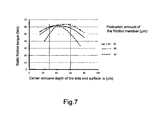
- the test was performed by using rotors 4 having a diameter of the outer peri pheral edge of the side end surface of ⁇ 112, a diameter of the inner peripheral edge of the side end surface of ⁇ 50, and three patterns of the protrusion amounts of the friction member 26 from the side end surface 4b of the rotor of 10 ⁇ m, 30 ⁇ m, and 50 ⁇ m that may be selected.
- Measured results of the static friction torque indicate characteristics illustrated by each line in Fig. 7 .
- the static friction torque indicates the highest value when the center concave depth ⁇ of the side end surface 4b of the rotor 4 is 40 ⁇ m to 50 ⁇ m, and if the center concave depth ⁇ is out of this proper region, the static friction torque is lowered. This may be because if the center concave depth ⁇ of the side end surface 4b of the rotor 4 is excessively great, when the side end surface 4b of the rotor 4 abuts the armature plate 5 at the portion close to the outer edge, the portion close to the inner edge of the rotor is in a state of being separated from the armature plate 5, and thus the attraction force over an entire surface of the armature is lowered.
- the armature plate 5 is in a state of mainly abutting by the friction member 26 protruding in the portion close to the inner edge of the side end surface 4b, and a surface pressure in the region close to the outer periphery of the side end surface of the rotor 4 is weakened.
- the static friction torque is ensured to be, for example, 50 N ⁇ m or more considering the torque generated during operation of the compressor.
- the protrusion amount of the friction member 26 is small from the viewpoint of stably ensuring the transmission torque regardless of the deviation in the center concave depth ⁇ .
- the friction member 26 wears with use, if the friction member 26 were set to be an excessively small value, it would lead to sliding between metals in the vicinity of the inner periphery by wear of the friction member 26 in an early stage.
- the protrusion amount of the friction member 26 is 10 ⁇ m of the protrusion amount of the friction member 26 as the lower limit value in a tolerance range.
- the upper limit value of the protrusion amount is 50 ⁇ m.
- setting the center concave depth ⁇ with a range of 30 ⁇ m to 60 ⁇ m and thereby it is possible to ensure the static friction torque (50 N ⁇ m or more) to be a target even if the protrusion amount of the friction member 26 is varied in a range from the upper limit value (50 ⁇ m) to the lower limit value (10 ⁇ m) .
- the center concave depth ⁇ is set to be a range of 30 ⁇ m to 60 ⁇ m and the protrusion amount of the friction member 26 is set to be a range of 10 ⁇ m to 50 ⁇ m. Moreover, it is further preferable that the protrusion amount of the friction member 26 is set in a range of 15 ⁇ m to 40 ⁇ m to reduce the variation of the static friction torque.
- a time (fusing time of the temperature fuse) until the connection of the clutch was released by the temperature fuse 15 being fused was measured ( Fig. 8 ).
- the test was performed by rotating the rotor 4 of the electromagnetic clutch, which was used for the static friction test of Fig. 7 described above, while slipping with the armature plate 5 that was forcedly non-rotatable.
- the fusing time (sec) of the temperature fuse is a time until the temperature fuse 15 is fused (electromagnetic attracting force that attracts the armature plate 5 to the rotor 4 is extinguished) by friction heat generated by the slip from the slip being started between the rotor 4 that is rotated by receiving the rotational force from an engine and the armature plate 5 that is connected to the driving shaft 20 of the compressor 2 that becomes unable to rotate. It is preferable to be shorter so as not to apply a burden to the engine or the belt, for example, within 80 seconds as a target.
- characteristics of the fusing time of the temperature fuse indicated substantially the same tendency as characteristics of the static friction torque. That is, if the center concave depth ⁇ of the side end surface of the rotor 4 is greater or smaller than the proper range, the static friction torque is decreased. Thus, occurring friction heat may be decreased and the time required until the temperature fuse is fused may be increased.
- the center concave depth ⁇ of the side end surface of the rotor is set to be in a range of 30 ⁇ m to 60 ⁇ m from the viewpoint of ensuring a required transmission torque and rapidly fusing the temperature fuse 15 during lock of the compressor. Furthermore, it is preferable that the protrusion amount of the friction member 26 at its outside portion in the radial direction is set to be in a range of 10 ⁇ m to 50 ⁇ m, and it is further preferable that the protrusion amount of the friction member 26 at its outside portion in the radial direction is set to be a range of 15 ⁇ m to 40 ⁇ m.
- a center value of the tolerance of the center concave depth ⁇ of the side end surface of the rotor is set to be proximately 1.5 times the protrusion amount of the friction member 26 from the side end surface of the rotor 4.
- the friction member 26 comes into contact with the armature plate 5 in the region close to the inner periphery in which the peripheral speed is slow and thereby it is possible to prevent the sticking phenomenon by preventing slip between metals when the compressor 2 becomes unable to rotate. Furthermore, since the side end surface 4b of the rotor 4 has the center concave shape, it is possible to ensure a sufficient surface pressure and then to maintain the transmission torque even in the region close to the outer periphery of the rotor 4.
- the friction member 26 comes into contact with the armature plate 5, there is a concern that the surface pressure is low and the transmission torque is decreased in the portion outside from the contact portion in the radial direction only by protruding the friction member 26 provided in the portion close to the inner periphery of the rotor 4.
- the side end surface 4b of the rotor 4 has the center concave shape and thereby the outer periphery side further than the friction member 26 can actively come into contact with the armature plate from initial use and the friction torque can be stably ensured from initial use.
- the friction member 26 comes into contact with the armature plate 5 prior to the portion close to the outer periphery of the rotor 4 and thereby a process of the wear of the friction member 26 is fast.
- the preventing function of sticking may be early deteriorated.
- both the metal surface of the side end surface 4b on the outer periphery side and the friction member 26 on the inner periphery side can come into contact with the armature plate 5 from initial use, significant wear only in the friction member 26 can be avoided, and the avoiding function of sticking between the rotor 4 and the armature plate 5 can be sustained over a further long period of time.
- the side end surface of the rotor is configured to have the center concave shape such that a separation distance between the side end surface of the rotor and the armature plate is decreased toward the outside in the radial direction, but instead thereof, even if the surface (contact surface) of the armature plate facing the side end surface of the rotor has a similar center concave shape, the same operational effects can be expected.
- the side end surface 4b of the rotor 4 having the center concave shape is applied to the configuration in which Lhe friction member 26 is provided in the annular groove 25 formed in the portion where the inner magnetic blocking portion 22 is formed, but as illustrated in Figs. 9A and 9B , the side end surface 4b of the rotor 4 having the center concave shape may be applied to a configuration in which the friction member 27 is also provided in the annular groove 24 where the outer magnetic blocking portion 21 is formed, both the friction member 26 on the inside and the friction member 27 on the outside come into contact with the armature plate 5 from initial use, thereby preventing significant wearing of only the friction member 26 on the inside.
Landscapes
- Engineering & Computer Science (AREA)
- General Engineering & Computer Science (AREA)
- Physics & Mathematics (AREA)
- Electromagnetism (AREA)
- Mechanical Engineering (AREA)
- Hydraulic Clutches, Magnetic Clutches, Fluid Clutches, And Fluid Joints (AREA)
- Compressors, Vaccum Pumps And Other Relevant Systems (AREA)
- Mechanical Operated Clutches (AREA)
Abstract
Description
- The present invention relates to an electromagnetic clutch used for connecting and disconnecting power transmitting from a power source to a compressor and, in particular, to an electromagnetic clutch in which a friction member is provided on a side end surface of a rotor onto which an armature plate comes in contact.
- As illustrated in Fiqs. 10A and 10B, a general electromagnetic clutch used in a compressor of a vehicular air conditioner includes a
rotor 4 that is formed of a magnetic material, is fitted onto an outer periphery of acylindrical portion 16 through abearing 14 to be rotatable in which adriving shaft 20 of acompressor 2 is journaled, and is rotated by receiving a rotational force from a rotation driving source; anarmature plate 5 that is formed of a magnetic material, is connected to thedriving shaft 20 to be relatively non-rotatable, and is disposed to face a side end surface of therotor 4 across a slight gap; anexcitation coil 3 that is accommodated in an inside of therotor 4, forms a magnetic circuit through therotor 4 and thearmature plate 5 by being energized, and generates an attracting force that electromagnetically attracts thearmature plate 5 onto therotor 4; an outermagnetic blocking portion 21 provided on the side end surface of therotor 4, that is configured with an annular shape centered on thedriving shaft 20 or a plurality of arc shapes disposed on a virtual circle centered on thedriving shaft 20; an innermagnetic blocking portion 22 provided on the end surface of therotor 4, that is configured with an annular shape centered on thedriving shaft 20 or a plurality of arc shapes disposed on a virtual circle centered on thedriving shaft 20, which is provided inside further than the outermagnetic blocking portion 21 in a radial direction; and an intermediatemagnetic blocking portion 23 provided in thearmature plate 5, that is configured with an annular shape centered on thedriving shaft 20 or a plurality of arc shapes disposed on a virtual circle centered on thedriving shaft 20, which is formed in a position facing a position between the outermagnetic blocking portion 21 and the innermagnetic blocking portion 22 in the radial direction. - A temperature fuse 15 which blocks electric connection to the
excitation coil 3 when exceeding a predetermined temperature is provided on theexcitation coil 3 side from the side end surface of therotor 4. If thecompressor 2 becomes unrotatable for some reason, slip occurs between therotor 4 that is rotated by receiving the rotational driving force from the driving source and thearmature plate 5 that is connected to thedriving shaft 20 of thecompressor 2 that is unrotatable. Thetemperature fuse 15 is fused by friction heat caused by the slip and a connection of the clutch is cut (electromagnetic attracting force that attracts thearmature plate 5 onto therotor 4 is removed) by blocking electric connection to theexcitation coil 3. - In addition, in order to reduce occurrence of unpleasant noise when the
armature plate 5 hits on therotor 4, a configuration is proposed in which anannular groove 24 is formed on the side end surface of therotor 4 facing thearmature plate 5 so as to include the outermagnetic blocking portion 21, and a ring-shaped friction member 27 formed of a non-magnetic material such as thermosetting resin is mounted on theannular groove 24 in a state of being slightly protruded from theside end surface 4b of therotor 4. In this configuration, when thearmature plate 5 is attracted toward therotor 4 side by the electromagnetic force of theexcitation coil 3, thearmature plate 5 comes in contact with thefriction member 27 before coming into contact with the side end surface of the rotor 4 (JP 2008-014444 A - The
friction member 27 is disposed to cover the outermagnetic blocking portion 21 for ensuring a magnetic path and is slightly protruded from the side end surface of therotor 4. Since thefriction member 27 and thearmature plate 5 have an elasticity in themselves, when thearmature plate 5 is attracted to therotor 4, thearmature plate 5 comes into contact not only with thefriction member 27 but also with theside end surface 4b of therotor 4 in a region close to an inner periphery than thefriction member 27. As described above, when therotor 4 and thearmature plate 5 are engaged, both of thefriction member 27 and the inward region of the side end surface than thefriction member 27 come contact with thearmature plate 5 ,thereby performing stable transmission of torque. - However, if the compressor becomes unable to rotate and slip occurs between the
rotor 4 and thearmature plate 5, sliding occurs at a portion close to the inner periphery of therotor 4 and thearmature plate 5, which are similar magnetic metal materials, and hence adhesion is likely to occur. If the adhesion between similar metal materials occurs at a region close to an outer periphery of which a peripheral speed is fast, a relative speed difference is large, generated friction heat is also large, and thereby it does not lead to sticking. However, if the adhesion occurs at a region close to the inner periphery of which the peripheral speed is slow, since both a difference in a relative speed and occurring friction heat are small, hardening is likely to occur between melted metals and a sticking phenomenon of a sliding surface is caused before thetemperature fuse 15 is operated. As a result, there is a concern that the engagement of the clutch is not disengaged without fusing of thetemperature fuse 15. - The invention is made in view of the above circumstances and a main object of the invention is to provide an electromagnetic clutch in which a concern of sticking between a rotor and an armature plate is avoided and a temperature fuse can be reliably fused even if slip occurs between the rotor and the armature plate.
- According to an aspect of the present invention, there is provided an electromagnetic clutch characterized by including: a rotor that is formed of a magnetic material and is rotated by receiving a rotational force from a rotation driving source; an armature plate that is formed of the magnetic material, is connected to a driving shaft of a compressor to be relatively non-rotatable, and is disposed to face a side end surface of the rotor across a slight gap; an excitation coil that is accommodated in the inside of the rotor, forms a magnetic circuit through the rotor and the armature plate by being energized, and generates an attracting force magnetically attracting the armature plate onto the rotor; a temperature fuse that is disposed on the excitation coil side further than the side end surface of the rotor and blocks the electric connection to the excitation coil when exceeding a predetermined temperature; an outer magnetic blocking portion provided on the side end surface of the rotor, which is configured with an annular shape centered on the driving shaft or a plurality of arc shapes disposed on a virtual circle centered on the driving shaft; an inner magnetic blocking portion provided on the side end surface of the rotor, which is configured with an annular shape centered on the driving shaft or a plurality of arc shapes disposed on the virtual circle centered on the driving shaft, which is provided inside further than the outer magnetic blocking portion in a radial direction; and an intermediate magnetic blocking portion provided in the armature plate, which is configured with an annular shape centered on the driving shaft or a plurality of arc shapes disposed on the virtual circle centered on the driving shaft, which is formed in a position facing a position between the outer magnetic blocking portion and the inner magnetic blocking portion in the radial direction, in which four poles are formed by opposing surfaces formed on outside and inside of each blocking portion of the outer magnetic blocking portion, the intermediate magnetic blocking portion, and the inner magnetic blocking portion in the radial direction by disposing the rotor and the armature plate so as to face each other, in which an annular groove is formed on the side end surface of the rotor so as to include the inner magnetic blocking portion, and in which a friction member protruding from the side end surface of the rotor is disposed in the annular groove.
- Consequently, the friction member is disposed in the annular groove formed so as to include the inner magnetic blocking portion of the side end surface of the rotor so as to protrude from the side end surface of the rotor. Thus, even if slip occurs between the rotor and the armature plate for some reason, the rotor and the armature plate come into contact with each other through the friction member in the region close to the inside of which a peripheral speed is slow. Thus, it is possible to avoid a concern that the rotor and the armature plate come into slide contact with each other and then are stuck together.
- Preferably, an annular groove, which includes the outer magnetic blocking portion and narrows a width of a magnetic path (a width of the pole in a radial direction) at the outside of the outer magnetic blocking portion so as to dispose the magnetic path radially outward, is formed on the side end surface of the rotor.
- By adding this configuration, the pole of the outside of the annular groove including the outer magnetic blocking portion is configured in a position further from a rotational center of
Lhe rotor 4 and it is possible to improve transmission of a torque from the rotor to the armature plate. - In the aspect, the friction member protruding from the side end surface of the rotor may be further disposed in the annular groove formed to include the outer magnetic blocking portion.
- According to such a configuration, the armature plate comes into contact with the friction member before the armature plate comes into contact with the rotor when being attracted, even in the vicinity of the outer peripheral edge of the rotor and the armature plate. Thus, it is possible to reduce impact noise.
- In the aspect, it is preferable that the poles configure a first pole, a second pole, a third pole, and a fourth pole from the outside in the radial direction, and the third pole has a width in the radial direction of 60% or more of a width of the second pole in the radial direction.
- Disposing the friction member so as to include the inner magnetic blocking portion, there is a concern that a magnetic path may be excessively narrowed on both sides of the inner magnetic blocking portion in the radial direction. However, it is possible to ensure the attracting force by making the width of the third pole in the radial direction be 60% or more of the width of the second pole in the same direction without increasing a magnetic resistance.
- In the aspect, the side end surface of the rotor may be formed in a center concave shape such that a separation distance from the armature plate is reduced toward the outside in the radial direction during electric disconnection to the excitation coil. Alternatively, a side end surface of the armature plate facing the side end surface of the rotor may be formed in a center concave shape such that a separation distance from the side end surface of the rotor is reduced toward the outside in the radial direction during electric disconnection to the excitation coil.
- In such a configuration, the outer periphery side further than the friction member can come into contact with the armature plate from an initial use and the transmission of a torque by the friction can be stably ensured while avoiding a concern of sticking by slip between metals (slide contact between the rotor and the armature plate) when the compressor becomes unable to rotate.
- Furthermore, both the metal surface on the outer periphery side of the side end surface and the friction member on the inner periphery side come into contact with the armature plate from the initial use. Thus, it is possible to avoid the phenomenon that only the friction member is significantly worn.
- In the aspect, it is preferable that a center concave depth of the side end surface of the rotor or the side end surface of the armature plate may be formed such that an inner peripheral edge of the side end surface is lower than an outer peripheral edge of the side end surface by 30 µm to 60 µm. Further, a protrusion amount of the friction member from the side end surface of the rotor is 10 µm to 50 µm.
- As described above, according to the invention, the annular groove is provided so as to include the inner magnetic blocking portion. Thus, formation of the poles is not inhibited on the outside and the inside of the magnetic blocking portion in the radial direction by the annular groove. In addition, thanks to the friction member provided in the position of the inner magnetic blocking portion, it helps to transmit the torque during normal operation and makes it possible to avoid a concern of sticking between similar types of metals even if slip occurs between the rotor and the armature plate for some reason, since the slip at the region close to the inside where the peripheral speed is rather slow is made between the rotor and the armature plate through the friction member.
- Therefore, friction heat generated by slip between the friction member and the armature plate is reliably detected by the temperature fuse disposed on the excitation coil side further than the side end surface of the rotor, the electric connection to the excitation coil is rapidly blocked, and it is possible to ensure a failsafe function.
- In addition, the annular groove including the outer magnetic blocking portion and narrowing the width of the magnetic path (width of pole in the radial direction) at the outside of the outer magnetic blocking portion so as to dispose the magnetic path radially outward is formed on the side end surface of the rotor. Thus, the pole on the outside of the annular groove is configured in the position further from the rotational center of the rotor and it is possible to improve the transmission of a torque from the rotor to the armature plate.
- Furthermore, the friction member is also provided in the annular groove on the outside of the rotor. Thus, it is possible to further stably transmit the torque and there is no concern of adhesion or sticking after adhesion when the slip occurs, since the rotor and the armature plate slide through the friction members also in the region close to the outer periphery in addition to the region close to inner periphery.
- Moreover, there may be a concern that the magnetic path of the pole formed between the intermediate magnetic blocking portion and the inner magnetic blocking portion is narrowed by providing the annular groove for mounting the friction member so as to include the inner magnetic blocking portion. However, a significant increase in the magnetic resistance is not caused and it is possible to ensure required sufficient attracting force regardless of mounting of the friction member by setting the width of the pole to be 60% or more of the width of the magnetic path of the pole formed between the outer magnetic blocking portion and the intermediate magnetic blocking portion.
- Furthermore, the side end surface of the rotor is formed such that the distance from the armature plate during the electric disconnection of the excitation coil is decreased toward the outside in the radial direction or the side end surface of the armature plate facing the side end surface of the rotor is formed such that the distance from the side end surface of the rotor during the electric disconnection of the excitation coil is decreased toward the outside in the radial direction. Thus, a sufficient surface pressure is ensured even in the region close to the outer periphery of the rotor, and thus it is possible to maintain the transmission of a torque during a normal operation of the compressor. In addition, both the metal surface on the outer periphery side of the side end surface and the friction member on inner periphery side come into contact with the armature plate from the initial use. Thus, it is possible to avoid the phenomenon that only Lhe friction member is significantly worn and to maintain the function for avoiding sticking between the rotor and the armature plate over a longer period of time.
-
-
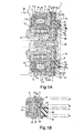
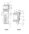
Figs. 1A and 1B are cross-sectional views illustrating a first embodiment of an electromagnetic clutch according to the invention,Fig. 1A is a view illustrating an entire configuration thereof, andFig. 1B is an enlarged cross-sectional view of a portion close to an outer periphery. -
Figs. 2A, 2B, and 2C are views illustrating a rotor used in the electromagnetic clutch,Fig. 2A is a side view of the rotor in which a portion thereof is cut out,Fig. 2B is a cross-sectional view of a vicinity (portion in which an excitation coil is accommodated) of a peripheral edge of the rotor, andFig. 2C is a front view of the rotor. -
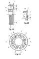
Figs. 3A and 3B are views illustrating an armature plate used in the electromagnetic clutch,Fig. 3A is a side cross-sectional view thereof, andFig. 3B is a front view of the armature plate. -
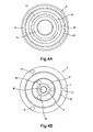
Fig. 4A is a view illustrating a side end surface of the rotor facing the armature plate andFig. 4B is a view of the electromagnetic clutch viewed from an axial direction of a driving shaft. -
Fig. 5 is a cross-sectional view illustrating a modification example of the first embodiment of the electromagnetic clutch according to the invention, -
Figs. 6A and 6B are cross-sectional views illustrating a second embodiment of an electromagnetic clutch according to the invention,Fig. 6A is a view illustrating an entire configuration thereof, andFig. 6B is an enlarged view illustrating a part ofFig. 6A . -
Fig. 7 is a characteristic line diagram illustrating a relationship of a static friction torque with respect to setting of a center concave depth of the side end surface of the rotor. -
Fig. 8 is a characteristic line diagram illustrating a relationship of a fusing time of a temperature fuse with respect to setting of the center concave depth of the side end surface of the rotor. -
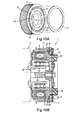
Figs. 9A and 9B are cross-sectional views illustrating a modification example of the second embodiment of the electromagnetic clutch according to the invention.Fig. 9A is a view illustrating an entire configuration thereof, andFig. 9B is an enlarged view illustrating a part ofFig. 9A . -
Figs. 10A and 10B are views illustrating an electromagnetic clutch of the related art,Fig. 10A is a perspective view of a rotor, andFig. 10B is a side sectional view. - Hereinafter, embodiments of an electromagnetic clutch of the invention will he described with reference to the accompanying drawings.
- In
Figs. 1A and 1B , a first embodiment of anelectromagnetic clutch 1 is illustrated. Theelectromagnetic clutch 1 can intermittently supply a rotational driving force from a power source such as an engine or a motor to acompressor 2 that is a driven apparatus. Theelectromagnetic clutch 1 includes arotor 4 that is supported to be rotatable centered on a drivingshaft 20 of thecompressor 2, anarmature plate 5 that faces therotor 4 in an axial direction, ahub 6 that is fixed to the drivingshaft 20 of thecompressor 2 and rotates together with the drivingshaft 20, anouter plate 7 that is connected to thearmature plate 5, aninner plate 8 that is connected to thehub 6, and anelastic member 10 that is interposed between theouter plate 7 and theinner plate 8. - The
rotor 4 is formed in an annular shape by a magnetic material, as illustrated inFigs. 2A to 2C , is formed ofgrooves 4a for mounting a coupling belt for coupling the driving source to an outer periphery thereof, is provided with a bearing 14 on an inner periphery, and is fitted onto an outer periphery of acylindrical portion 16 through the bearing 14 to be rotatable in which the drivingshaft 20 protruding from ahousing 2a of thecompressor 2 is jounaled. Aside end surface 4b of therotor 4 that is opposite to a body of thecompressor 2 is formed in a planar shape that is substantially perpendicular to an axis of therotor 4, and configures a friction surface facing thearmature plate 5 described below. - As illustrated in
Figs. 3A and 3B , thearmature plate 5 is formed in a disk shape by a magnetic material, is fixed to theouter plate 7 described below, and has aside end surface 5a facing theside end surface 4b of therotor 4 across a slight gap. Theside end surface 5a is configured of a friction surface that is formed in a planar shape that is substantially perpendicular to the axis of therotor 4 and faces therotor 4. - An
excitation coil 3 is accommodated in acoil groove 11a of astator housing 11 and is wound around abobbin 12 fixed by aresin mold 11b. Thestator housing 11 in which theexcitation coil 3 is accommodated is fixed to thehousing 2a of thecompressor 2 through a mountingplate 13. Therotor 4 is provided with anannular space 41 which is opened to the housing of thecompressor 2. Thestator housing 11 in which theexcitation coil 3 is housed in theannular space 41 with a predetermined clearance. - Thus, the
rotor 4 is provided so as to cover theexcitation coil 3 from the armature plate side and rotates along the excitation coil without coming into contact with theexcitation coil 3. - A
temperature fuse 15, which is fused when exceeding a predetermined temperature and blocks the electric connection to theexcitation coil 3, is provided on the excitation coil side further than theside end surface 4b of therotor 4. For example, the temperature fuses 15 are fixed to the vicinity of an opening end of thecoil groove 11a of thestator housing 11 by theresin mold 11b. A plurality of temperature fuses 15 may be provided along theexcitation coil 3 and are connected to theexcitation coil 3 in series, and the electric connection to theexcitation coil 3 is blocked if one of the temperature fuses 15 is fused. - Meanwhile, on the
side end surface 4b of therotor 4, an outer magnetic blockingportion 21 and an inner magnetic blockingportion 22, which make a passage of magnetic flux generated by energizing theexcitation coil 3 go around by blocking the passage thereof, are intermittently formed in a circumferential direction along virtual circles of which distances from the axis (driving shaft 20) of therotor 4 are different. - That is, as illustrated in
Figs. 2A to 2C , the outermagnetic blocking portions 21 are configured by forming four arc-shaped long holes on the virtual circle centered on the axis of therotor 4 at regular intervals. In addition, the innermagnetic blocking portions 22 are configured by forming six arc-shaped long holes on the virtual circle of which a diameter is smaller than that of the virtual circle of the outermagnetic blocking portions 21 centered on the axis of therotor 4 at regular intervals. - On the other hand, on the
side end surface 5a of thearmature plate 5, an intermediate magnetic blockingportion 23 for making the magnetic flux generated by energizing theexcitation coil 3 go aound is provided in a position shifted in the radial direction from themagnetic blocking portions side end surface 4b of therotor 4. - That is, as illustrated in
Figs. 3A and 3B , in this example, the intermediate magnetic blockingportion 23 is configured by a ring-shapedmember 53 made of a non-magnetic metal and thearmature plate 5 is formed by one disk-shaped plate having no hole by sticking the ring-shapedmember 53 between an outerannular plate 51 and an inner annular plate 52 made of a magnetic metal. - Thus, in a state where the
rotor 4 and thearmature plate 5 face each other by matching the axes thereof, a first pole A is formed in a portion on the outside of the outer magnetic blockingportion 21 in the radial direction, a second pole B is formed in a portion between the outer magnetic blockingportion 21 and the intermediate magnetic blockingportion 23, a third pole C is formed between the intermediate magnetic blockingportion 23 and the inner magnetic blockingportion 22, a fourth pole D is formed in a portion of the inside of the inner magnetic blockingportion 22 in the radial direction, a magnetic circuit in which magnetic flux passes through a periphery of theexcitation coil 3 via the first pole A, the second pole B, the third pole C, and the fourth pole D is formed by enegizing theexcitation coil 3, and thereby a attracting force that attracts thearmature plate 5 to therotor 4 is generated. - The
outer plate 7 is configured to have acylindrical holding portion 7a extending in the axial direction for holding theelastic member 10 and a flange 7b extending from an end portion of the holdingportion 7a on the armature plate side along a surface of thearmature plate 5, and is fixed to thearmature plate 5 byrivets 17 mounted on the flange 7b. - The
hub 6 is fixed to the end portion of the drivingshaft 20 by abolt 18 and theinner plate 8 is fixed to aflange 6b extending in the radial direction from a body 6a of thehub 6 fixed to the drivingshaft 20 byrivets 19. Theinner plate 8 is a body separated from thehub 6, has a substantially disk shape, and is configured to have abase portion 8a that is put on theflange 6b of thehub 6 and is fixed by therivets 19, and a holdingportion 8b that is erected from an outer peripheral edge of thebase portion 8a along the axial direction in a substantially cylindrical shape and holds theclastic member 10. - Then, as also illustrated in
Fig. 4B , theouter plate 7 and theinner plate 8 are arranged on the same plane, theelastic member 10 is interposed in anannular space 9 formed between the holdingportion 7a of theouter plate 7 and the holdingportion 8b of theinner plate 8, theelastic member 10 is adhered to both theouter plate 7 and theinner plate 8, and thereby theouter plate 7 and theinner plate 8 are connected through theelastic member 10. - The
elastic member 10 is configured of an annular-shaped synthetic rubber (NBR, chlorinated butyl, and the like) provided around an entire periphery of the holdingportion 7a of theouter plate 7 and the holdingportion 8b of theinner plate 8, a torque fluctuation in a rotation direction is absorbed by twisting, and thus damage of the drivingshaft 20 and the like resulting from the torque fluctuation is prevented. In addition, deformation due to thearmature plate 5 attracted to therotor 4 is allowed by the elasticity of theelastic member 10. If theexcitation coil 3 is enegized, thearmature plate 5 is attracted onto the side end surface side of therotor 4 by the elastic deformation of theelastic member 10 and if theexcitation coil 3 is deeneqized, thearmature plate 5 is separated from the side end surface of therotor 4 by a restoring force of theelastic member 10. - In the configuration described above, as also illustrated in
Fig. 4A , anannular groove 25 formed in a circular shape is formed on theside end surface 4b of therotor 4 centered on the axis of therotor 4 so as to include the inner magnetic blockingportion 22, and afriction member 26 is disposed in theannular groove 25. - The
friction member 26 is configured ot a non-magnetic material, is formed in a circular shape and in a planar shape having a diameter according to a size of theannular groove 25, is accommodated and fixed in theannular groove 25 so that the surface facing thearmature plate 5 slightly protrudes (in this example, it becomes 0.010 mm to 0.050 mm) from theside end surface 4b of therotor 4. - The
friction member 26 is provided to obtain functions for a predetermined elastic deformation, reduction of impact noise, torque transmission, wear resistance, and the like. For example, thefriction member 26 can be formed by using a material in which a base material is formed of a fiber material such as aramid fiber, nonferrous metal fiber, and inorganic fiber, in which a filler, friction-characteristic improving material, and the like are mixed, and which is combined with a binder such as phenol resin. - The attracting force can be controlled by adjusting a width in the radial direction between the second pole B and the third pole C based on the positional relationship between the inner magnetic blocking
portion 22 on which thefriction member 26 is mounted and the intermediate magnetic blockingportion 23 of thearmature plate 5. In this example, the width of the third pole C in the radial direction is set to be 60% or more of the width of the second pole B in the radial direction for ensuring a friction torque by thefriction member 26 or the attracting force of each pole. - Furthermore, in this example, an
annular groove 24 is formed on theside end surface 4b of therotor 4 so as to include the outer magnetic blockingportion 21. Since theannular groove 24 is formed in a circular shape centered on the axis of therotor 4, theannular groove 24 is formed having a depth equivalent to or shallower than a depth of theannular groove 25. - Based on the configuration described above, a basic operation and the like of the
electromagnetic clutch 1 are described below. When theexcitation coil 3 is not energeized, thearmature plate 5 is in a state of being separated from theside end surface 4b of therotor 4 by an elastic force of theelastic member 10 mounted through theouter plate 7, and therotor 4 is in a state of being idle. On the other hand, if theexcitation coil 3 is enegized, as illustrated inFigs. 1A and 1B , the magnetic circuit is formed in therotor 4 and thearmature plate 5, a magnetic attraction force is generated, and thearmature plate 5 is attracted onto therotor 4 side against the elastic force of theelastic member 10. - In this case, the
armature plate 5 initially abuts thefriction member 26 which is provided on theannular groove 25 so as to protrude from theside end surface 4b of therotor 4. Thus, the impact noise when thearmature plate 5 comes into contact with theside end surface 4b of therotor 4 is reduced. Then, a portion close to the outer periphery of thearmature plate 5 abuts a portion close to the outer periphery of theside end surface 4b of therotor 4 by the elastic deformation of thefriction member 26 and the elastic deformation of thearmature plate 5 itself after thearmature plate 5 abuts thefriction member 26. Thus, the rotation of therotor 4 is transmitted from thearmature plate 5 to the drivingshaft 20 of thecompressor 2 through theouter plate 7, theelastic member 10, theinner plate 8, and thehub 6 by the friction between thefriction member 26 and thearmature plate 5 in a portion close to the inner periphery of therotor 4, and by the friction between therotor 4 and thearmature plate 5 in a portion close to the outer periphery of therotor 4. - Thus, if the
compressor 2 becomes unable to rotate and slip occurs between therotor 4 and thearmature plate 5 for some reason, at the portion close to the inner periphery of therotor 4, sliding occurs between the magnetic metal and thefriction member 26 being nonmetal. Thus, the slide contact portion is not stuck by adhering. As a result, the slipping state is sustained and friction heat generated by the sliding between therotor 4 and thearmature plate 5 is transmitted to thetemperature fuse 15. Thus, thetemperature fuse 15 is rapidly fused and it is possible to reliably cut the connection of the clutch. - Incidentaly, sliding at the portion close to the outer periphery of the
rotor 4 is performed between the magnetic bodies made of the similar metal. A peripheral speed at the region close to the outer periphery of therotor 4 is rather fast. Thus, even if partial adhesion occurs, since a difference in relative speeds is great and the generated friction heat is also large, a sticking phenomenon of the sliding surface does not occur. - Particularly, in the configuration example described above, the
side end surface 4b of therotor 4 is provided with theannular groove 24 which includes the outer magnetic blockingportion 21 and narrows a width of magnetic path (width of the first pole A in the radial direction) at the outside of the outer magnetic blockingportion 21 in the radial direction so as to dispose the magnetic path radially outward. Thus, the first pole A is configured in a position away from a rotation center of therotor 4 and it is possible to improve the transmission of the torque from therotor 4 to thearmature plate 5. Incidentally, as theannular groove 24 is provided for narrowing the magnetic path width of the first pole A so as to dispose the magnetic path radially outward, there is a concern that a magnetic resistance may be increased if the magnetic path width of the first pole A is excessively narrowed. In this example, the width of the first pole A in the radial direction is set to be 70% or more of the width of the second pole B in the radial direction. - Incidentally, in the configuration example described above, in the portion where the inner magnetic blocking
portion 22 of therotor 4 is formed, theannular groove 25 is formed to includes this portion, and thefriction member 26 is provided in theannular groove 25. In the portion where the outer magnetic blockingportion 21 is formed, only theannular groove 24 is formed on its outside to include this portion. However, as illustrated inFig. 5 , anannular friction member 27 may be further mounted on theannular groove 24 including the outer magnetic blockingportion 21. Thefriction member 27 is also configured of a non-magnetic material and is formed in an annular shape and a planar shape according to the size of theannular groove 24. Thus, thefriction member 27 is fixed so as to slightly protrude from theside end surface 4b of therotor 4. - According to such a configuration, when the
excitation coil 3 is energized and thearmature plate 5 is attracted to therotor 4, thearmature plate 5 comes into contact with thefriction members side end surface 4b of therotor 4 before thearmature plate 5 comes in contact with theside end surface 4b of therotor 4. Thus, it is possible to further stably transmit the torque and to further reduce a concern of adhesion or sticking. In addition, it is possible to further reduce occurrence of the impact noise. - Furthermore, in the configuration described above, an example is illustrated in which the outer magnetic blocking
portion 21 or the inner magnetic blockingportion 22 is configured by forming arc-shaped long holes on a virtual circle centered on the drivingshaft 20 at regular intervals. However, it may be configured by interposing an annular-shaped non-magnetic material centered on the drivingshaft 20. Furthermore, in the configuration described above, an example is illustrated in which the intermediate magnetic blockingportion 23 is configured by interposing the annular-shaped non-magnetic material centered on the drivingshaft 20. However, it may be configure by forming arc-shaped long holes on a virtual circle centered on the drivingshaft 20 at regular intervals. - A second embodiment of an
electromagnetic clutch 1 is illustrated inFigs. 6A and 6B (for convenience of explanation, the description is exaggerated). Theelectromagnetic clutch 1 is different from that of the first embodiment in that aside end surface 4b of arotor 4 facing anarmature plate 5 is formed in a center concave shape including an linear inclined surface which is gradually inclined downward (continuously inclined such that the inner peripheral edge is lower than the outer peripheral edge of the rotor 4) on the inside of therotor 4 in the axial direction toward the center of therotor 4 in the radial direction. That is, in the de-energized state in which thearmature plate 5 is not attracted, a distance separated from thearmature plate 5 is decreased toward outside in the radial direction. - In this example, the
friction member 26 provided in theannular groove 25 that is formed so as to include a portion where the inner magnetic blockingportion 22 of therotor 4 is provided is formed such that the portion protruding from theside end surface 4b of therotor 4 is not inclined (is not provided parallel to theside end surface 4b of the rotor 4) together with theside end surface 4b of therotor 4, but is perpendicular to the drivingshaft 20 from the portion outside thefriction member 26 in the radial direction. - A protrusion amount (protrusion amount of the portion outside the
friction member 26 in the radial direction) of thefriction member 26 from theside end surface 4b and a center concave depth α (that is a distance between a plane perpendicular to the drivingshaft 20 including the outer peripheral edge of the side end surface of the rotor and a plane perpendicular to the drivingshaft 20 including the inner peripheral edge of theside end surface 4b of therotor 4, and an amount by which the inner peripheral edge of the side end surface is lower than the outer peripheral edge of the side end surface) of the side end surface of the rotor are set based on evaluation results described below. - In order to evaluate a torque transmission ability that is one of the functions that are required for the electromagnetic clutch, a change in a static friction torque (N·m) with respect to a change in the center concave depth α (µm) of the side end surface of the
rotor 4 was measured. The static friction torque of the electromagnetic clutch can be obtained by applying a voltage to the electromagnetic coil, attracting the armature plate to the rotor so as to engage, gradually adding a torque to the driving shaft connected to the armature, and measuring the torque that makes slip occur between the armature plate and the rotor which are engaged in a state where the rotor of the electromagnetic clutch is fixed so as not to rotate. Here, the test was performed by usingrotors 4 having a diameter of the outer peri pheral edge of the side end surface of Φ 112, a diameter of the inner peripheral edge of the side end surface of Φ 50, and three patterns of the protrusion amounts of thefriction member 26 from theside end surface 4b of the rotor of 10 µm, 30 µm, and 50 µm that may be selected. Measured results of the static friction torque indicate characteristics illustrated by each line inFig. 7 . - As can be seen from
Fig. 7 , the static friction torque indicates the highest value when the center concave depth α of theside end surface 4b of therotor 4 is 40 µm to 50 µm, and if the center concave depth α is out of this proper region, the static friction torque is lowered. This may be because if the center concave depth α of theside end surface 4b of therotor 4 is excessively great, when theside end surface 4b of therotor 4 abuts thearmature plate 5 at the portion close to the outer edge, the portion close to the inner edge of the rotor is in a state of being separated from thearmature plate 5, and thus the attraction force over an entire surface of the armature is lowered. If the center concave depth α of theside end surface 4b of therotor 4 is excessively small, thearmature plate 5 is in a state of mainly abutting by thefriction member 26 protruding in the portion close to the inner edge of theside end surface 4b, and a surface pressure in the region close to the outer periphery of the side end surface of therotor 4 is weakened. - Furthermore, as can be seen in the same view, even when the center concave depth α is deviated from the proper region, decreasing of the static friction torque can be lowered in a case where the protrusion amount of the
friction member 26 is 10 µm compared to a case where the protrusion amount of thefriction member 26 is 50 µm. - It is preferable that the static friction torque is ensured to be, for example, 50 N·m or more considering the torque generated during operation of the compressor. Thus, it seems to be preferable that the protrusion amount of the
friction member 26 is small from the viewpoint of stably ensuring the transmission torque regardless of the deviation in the center concave depth α. However, since thefriction member 26 wears with use, if thefriction member 26 were set to be an excessively small value, it would lead to sliding between metals in the vicinity of the inner periphery by wear of thefriction member 26 in an early stage. - Consequently, considering these design requirements and deviations required for manufacturing, it is preferable to regard 10 µm of the protrusion amount of the
friction member 26 as the lower limit value in a tolerance range. Meanwhile, assuming that a tolerance range of the protrusion amount of the friction member is 40 µm, the upper limit value of the protrusion amount is 50 µm. As illustrated inFig. 7 , setting the center concave depth α with a range of 30 µm to 60 µm and thereby it is possible to ensure the static friction torque (50 N·m or more) to be a target even if the protrusion amount of thefriction member 26 is varied in a range from the upper limit value (50 µm) to the lower limit value (10 µm) . - Consequently, it is preferable that the center concave depth α is set to be a range of 30 µm to 60 µm and the protrusion amount of the
friction member 26 is set to be a range of 10 µm to 50 µm. Moreover, it is further preferable that the protrusion amount of thefriction member 26 is set in a range of 15 µm to 40 µm to reduce the variation of the static friction torque. - Next, in order to investigate whether the
temperature fuse 15 is appropriately fused during lock of the compressor and the connection of the clutch can be cut, a time (fusing time of the temperature fuse) until the connection of the clutch was released by thetemperature fuse 15 being fused was measured (Fig. 8 ). The test was performed by rotating therotor 4 of the electromagnetic clutch, which was used for the static friction test ofFig. 7 described above, while slipping with thearmature plate 5 that was forcedly non-rotatable. - Here, the fusing time (sec) of the temperature fuse is a time until the
temperature fuse 15 is fused (electromagnetic attracting force that attracts thearmature plate 5 to therotor 4 is extinguished) by friction heat generated by the slip from the slip being started between therotor 4 that is rotated by receiving the rotational force from an engine and thearmature plate 5 that is connected to the drivingshaft 20 of thecompressor 2 that becomes unable to rotate. It is preferable to be shorter so as not to apply a burden to the engine or the belt, for example, within 80 seconds as a target. - As illustrated in
Fig. 8 , characteristics of the fusing time of the temperature fuse indicated substantially the same tendency as characteristics of the static friction torque. That is, if the center concave depth α of the side end surface of therotor 4 is greater or smaller than the proper range, the static friction torque is decreased. Thus, occurring friction heat may be decreased and the time required until the temperature fuse is fused may be increased. - In a set of the fusing tests of the temperature fuse, the fuse was safely fused and the sticking phenomenon did not occur in all tests, while differences in time until the temperature fuse was fused existed between each test. Furthermore, as illustrated in
Fig. 8 , if the center concave depth α is set to be in the proper range (30 µm to 60 µm) inFig. 7 , it is possible to makes the fusing time of the fuse within the target time (within 80 seconds) even if the protrusion amount of thefriction member 26 is varied in a range (protrusion amount is 10 µm to 50 µm) among the samples. - Thus, it is preferable that the center concave depth α of the side end surface of the rotor is set to be in a range of 30 µm to 60 µm from the viewpoint of ensuring a required transmission torque and rapidly fusing the
temperature fuse 15 during lock of the compressor. Furthermore, it is preferable that the protrusion amount of thefriction member 26 at its outside portion in the radial direction is set to be in a range of 10 µm to 50 µm, and it is further preferable that the protrusion amount of thefriction member 26 at its outside portion in the radial direction is set to be a range of 15 µm to 40 µm. Furthermore, it is preferable that a center value of the tolerance of the center concave depth α of the side end surface of the rotor is set to be proximately 1.5 times the protrusion amount of thefriction member 26 from the side end surface of therotor 4. - In addition, since other configurations are the same as the configurations illustrated in
Figs. 1A and 1B , the same reference numerals are given to the same portions and the description will be omitted. - In such the configuration, the
friction member 26 comes into contact with thearmature plate 5 in the region close to the inner periphery in which the peripheral speed is slow and thereby it is possible to prevent the sticking phenomenon by preventing slip between metals when thecompressor 2 becomes unable to rotate. Furthermore, since theside end surface 4b of therotor 4 has the center concave shape, it is possible to ensure a sufficient surface pressure and then to maintain the transmission torque even in the region close to the outer periphery of therotor 4. - That is, if the
friction member 26 comes into contact with thearmature plate 5, there is a concern that the surface pressure is low and the transmission torque is decreased in the portion outside from the contact portion in the radial direction only by protruding thefriction member 26 provided in the portion close to the inner periphery of therotor 4. However, theside end surface 4b of therotor 4 has the center concave shape and thereby the outer periphery side further than thefriction member 26 can actively come into contact with the armature plate from initial use and the friction torque can be stably ensured from initial use. - In addition, in the first embodiment in which the side end surface of the
rotor 4 does not have the center concave shape, thefriction member 26 comes into contact with thearmature plate 5 prior to the portion close to the outer periphery of therotor 4 and thereby a process of the wear of thefriction member 26 is fast. As a result, in a using situation in which the number of times of On-Off of theelectromagnetic clutch 1 is great, the preventing function of sticking may be early deteriorated. - On the other hand, in the second embodiment in which the
side end surface 4b of therotor 4 has the center concave shape, both the metal surface of theside end surface 4b on the outer periphery side and thefriction member 26 on the inner periphery side can come into contact with thearmature plate 5 from initial use, significant wear only in thefriction member 26 can be avoided, and the avoiding function of sticking between therotor 4 and thearmature plate 5 can be sustained over a further long period of time. - Moreover, in the example described above, the side end surface of the rotor is configured to have the center concave shape such that a separation distance between the side end surface of the rotor and the armature plate is decreased toward the outside in the radial direction, but instead thereof, even if the surface (contact surface) of the armature plate facing the side end surface of the rotor has a similar center concave shape, the same operational effects can be expected.
- Moreover, in the example described above, it is illustrated where the
side end surface 4b of therotor 4 having the center concave shape is applied to the configuration in whichLhe friction member 26 is provided in theannular groove 25 formed in the portion where the inner magnetic blockingportion 22 is formed, but as illustrated inFigs. 9A and 9B , theside end surface 4b of therotor 4 having the center concave shape may be applied to a configuration in which thefriction member 27 is also provided in theannular groove 24 where the outer magnetic blockingportion 21 is formed, both thefriction member 26 on the inside and thefriction member 27 on the outside come into contact with thearmature plate 5 from initial use, thereby preventing significant wearing of only thefriction member 26 on the inside. -
- 2
- compressor
- 3
- excitation coil
- 4
- rotor
- 4b
- side end surface
- 5
- armature plate
- 14
- bearing
- 15
- temperature fuse
- 20
- driving shaft
- 21
- outer magnetic blocking portion
- 22
- inner magnetic blocking portion
- 23
- intermediate magnetic blocking portion
- 24
- annular groove
- 25
- annular groove
- 26
- friction member
- 27
- friction member
- A
- first pole
- B
- second pole
- C
- third pole
- D
- fourth pole
Claims (8)
- An electromagnetic clutch (1) comprising:a rotor (4) that is formed of a magnetic material and is rotated by receiving a rotational force from a rotation driving source;an armature plate (5) that is formed of the magnetic material, is connected to a driving shaft (20) of a compressor (1) to be relatively non-rotatable, and is disposed to face a side end surface (4b) of the rotor (4) across a slight gap;an excitation coil (3) that is accommodated in the inside of the rotor (4), forms a magnetic circuit through the rotor (4) and the armature plate (5) by being energized, and generates an attracting force magnetically attracting the armature plate (5) onto the rotor (4);a temperature fuse (15) that is disposed on the excitation coil (3) side further than the side end surface (4b) of the rotor (4) and blocks the electric connection to the excitation coil (3) when exceeding a predetermined temperature;an outer magnetic blocking portion (21) provided on the side end surface (4b) of the rotor (4), which is configured with an annular shape centered on the driving shaft (20) or a plurality of arc shapes disposed on a virtual circle centered on the driving shaft (20);an inner magnetic blocking portion (22) provided on the side end surface (4b) of the rotor (4), which is configured with an annular shape centered on the driving shaft (20) or a plurality of arc shapes disposed on the virtual circle centered on the driving shaft (20), which is provided inside further than the outer magnetic blocking portion (21) in a radial direction; andan intermediate magnetic blocking portion (23) provided in the armature plate (5), which is configured with an annular shape centered on the driving shaft (20) or a plurality of arc shapes disposed on the virtual circle centered on the driving shaft (20), which is formed in a position facing a position between the outer magnetic blocking portion (21) and the inner magnetic blocking portion (22) in the radial direction,wherein four poles (A, B, C, D)are formed by opposing surfaces formed on outside and inside of each blocking portion of the outer magnetic blocking portion (21), the intermediate magnetic blocking portion (22), and the inner magnetic blocking portion (23) in the radial direction by disposing the rotor (4) and the armature plate (5) so as to face each other, characterized in thatan annular groove (25) is formed on the side end surface (4b) of the rotor (4) so as to include the inner magnetic blocking portion (22), andwherein a friction member (26) protruding from the side end surface (4b) ot the rotor (4) is disposed in the annular groove (25).
- The electromagnetic clutch (1) according to claim 1,
characterized in that an annular groove (24), which includes the outer magnetic blocking portion (21) and narrows a radial width of the pole (A) at the outside of the outer magnetic blocking portion (21) in the radial direction so as to dispose the pole (A) radially outward, is formed on the side end surface (4b) of the rotor (4). - The electromagnetic clutch (1) according to claim 2,
characterized in that the friction member (27) protruding from the side end surface (4b) of the rotor (4) is further disposed in the annular groove (24) formed so as to include the outer magnetic blocking portion (21). - The electromagnetic clutch (1) according to any one of claims 1 to 3,
characterized in that the poles (A, B, C, D) configure a first pole (A), a second pole (B), a third pole (C), and a fourth pole (D) from the outside in the radial direction, and the third pole (C) has a width in the radial direction of 60% or more of a width of the second pole (B) in the radial direction. - The electromagnetic clutch (1) according to any one of claims 1 to 4,
characterized in that the side end surface (4b) of the rotor (4) is formed in a center concave shape such that a separation distance from the armature plate (5) is reduced toward the outside in the radial direction during electric disconnection to the excitation coil (3). - The electromagnetic clutch (1) according to any one of claims 1 to 4,
characterized in that a side end surface of the armature plate (5) facing the side end surface (4b) of the rotor (4) is formed in a center concave shape such that a separation distance from the side end surface (4b) of the rotor (4) is reduced toward the outside in the radial direction during electric disconnection to the excitation coil (3). - The electromagnetic clutch (1) according to claim 5 or 6,
characterized in that the side end surface (4b) of the rotor (4) or the side end surface of the armature plate (5) is formed such that an inner peripheral edge of the side end surface (4b) is lower than an outer peripheral edge of the side end surface (4b) by 30 µm to 60 µm. - The electromagnetic clutch (1) according to any one of claims 5 to 7,
characterized in that a protrusion amount of the friction member (26) from the side end surface (4b) of the rotor (4) is 10 µm to 50 µm.
Applications Claiming Priority (2)
| Application Number | Priority Date | Filing Date | Title |
|---|---|---|---|
| JP2014161968 | 2014-08-08 | ||
| JP2015075944A JP6548941B2 (en) | 2014-08-08 | 2015-04-02 | Electromagnetic clutch |
Publications (3)
| Publication Number | Publication Date |
|---|---|
| EP2985484A2 true EP2985484A2 (en) | 2016-02-17 |
| EP2985484A3 EP2985484A3 (en) | 2016-08-17 |
| EP2985484B1 EP2985484B1 (en) | 2018-08-08 |
Family
ID=53886790
Family Applications (1)
| Application Number | Title | Priority Date | Filing Date |
|---|---|---|---|
| EP15002199.6A Active EP2985484B1 (en) | 2014-08-08 | 2015-07-24 | Electromagnetic clutch |
Country Status (4)
| Country | Link |
|---|---|
| US (1) | US10302154B2 (en) |
| EP (1) | EP2985484B1 (en) |
| JP (1) | JP6548941B2 (en) |
| CN (1) | CN105370754B (en) |
Families Citing this family (8)
| Publication number | Priority date | Publication date | Assignee | Title |
|---|---|---|---|---|
| CN105909691A (en) * | 2016-05-17 | 2016-08-31 | 廊坊市鑫佳机电有限公司 | Actuated clutch |
| CN105927677A (en) * | 2016-05-17 | 2016-09-07 | 廊坊市鑫佳机电有限公司 | Drive clutch |
| JP6645415B2 (en) * | 2016-12-16 | 2020-02-14 | 株式会社デンソー | Power transmission device |
| JP6680272B2 (en) * | 2017-06-23 | 2020-04-15 | 株式会社デンソー | Power transmission device |
| JP6747399B2 (en) * | 2017-07-28 | 2020-08-26 | 株式会社デンソー | Power transmission device |
| US11081947B2 (en) * | 2017-08-10 | 2021-08-03 | Hamilton Sundstrand Corporation | Claw pole brushless synchronous machine |
| JP7238832B2 (en) * | 2020-02-21 | 2023-03-14 | トヨタ自動車株式会社 | Vehicle electromagnetic clutch |
| CN116771823A (en) * | 2023-08-28 | 2023-09-19 | 成都瑞迪智驱科技股份有限公司 | Small-size large-torque permanent magnet brake |
Citations (1)
| Publication number | Priority date | Publication date | Assignee | Title |
|---|---|---|---|---|
| JP2008014444A (en) | 2006-07-07 | 2008-01-24 | Sanden Corp | Electromagnetic clutch and method of manufacturing the same |
Family Cites Families (20)
| Publication number | Priority date | Publication date | Assignee | Title |
|---|---|---|---|---|
| JPS57179429A (en) * | 1981-04-27 | 1982-11-05 | Matsushita Electric Ind Co Ltd | Electromagnetic clutch |
| JPS59151628A (en) * | 1983-02-16 | 1984-08-30 | Canon Electronics Inc | Electromagnetic clutch device |
| JP3252572B2 (en) * | 1993-11-22 | 2002-02-04 | 株式会社デンソー | Method for manufacturing rotor for electromagnetic clutch |
| JPH07224861A (en) * | 1993-08-31 | 1995-08-22 | Nippondenso Co Ltd | Electromagnetic clutch |
| US5404980A (en) * | 1994-04-11 | 1995-04-11 | Ford Motor Company | Electromagnetic clutch with failure protection apparatus |
| JP3627313B2 (en) * | 1995-03-29 | 2005-03-09 | 株式会社デンソー | Electromagnetic clutch |
| JP3837786B2 (en) * | 1996-09-12 | 2006-10-25 | 株式会社デンソー | Electromagnetic clutch |
| JP2001200860A (en) * | 1999-03-05 | 2001-07-27 | Nippon Soken Inc | Friction clutch |
| JP2004052985A (en) * | 2002-07-24 | 2004-02-19 | Zexel Valeo Climate Control Corp | Electromagnetic clutch |
| JP2005155699A (en) * | 2003-11-21 | 2005-06-16 | Matsushita Electric Ind Co Ltd | Electromagnetic clutch |
| JP2006009960A (en) * | 2004-06-25 | 2006-01-12 | Aisin Seiki Co Ltd | Clutch plate, and electromagnetic clutch mechanism employing the same clutch plate |
| DE102006007688B4 (en) * | 2006-02-20 | 2016-10-13 | Kern Antriebstechnik GmbH | Electromagnetically operated switching unit |
| JP4918406B2 (en) * | 2007-05-16 | 2012-04-18 | ミネベア株式会社 | Electromagnetic clutch |
| JP2010101441A (en) * | 2008-10-24 | 2010-05-06 | Sanden Corp | Electromagnetic clutch for compressor |
| JP2010281392A (en) * | 2009-06-04 | 2010-12-16 | Toyota Industries Corp | Electromagnetic clutch |
| JP2011169381A (en) * | 2010-02-17 | 2011-09-01 | Sinfonia Technology Co Ltd | Electromagnetic coupling device |
| JP2013100862A (en) * | 2011-11-08 | 2013-05-23 | Denso Corp | Electromagnetic clutch and method for manufacturing the same |
| JP6277781B2 (en) * | 2014-02-28 | 2018-02-14 | 株式会社デンソー | Electromagnetic clutch and method of manufacturing the electromagnetic clutch |
| JP6256119B2 (en) * | 2014-03-11 | 2018-01-10 | 株式会社デンソー | Friction clutch |
| JP6248773B2 (en) * | 2014-04-17 | 2017-12-20 | 株式会社デンソー | Power transmission device |
-
2015
- 2015-04-02 JP JP2015075944A patent/JP6548941B2/en active Active
- 2015-07-24 EP EP15002199.6A patent/EP2985484B1/en active Active
- 2015-08-06 US US14/819,625 patent/US10302154B2/en not_active Expired - Fee Related
- 2015-08-10 CN CN201510486522.1A patent/CN105370754B/en active Active
Patent Citations (1)
| Publication number | Priority date | Publication date | Assignee | Title |
|---|---|---|---|---|
| JP2008014444A (en) | 2006-07-07 | 2008-01-24 | Sanden Corp | Electromagnetic clutch and method of manufacturing the same |
Also Published As
| Publication number | Publication date |
|---|---|
| EP2985484B1 (en) | 2018-08-08 |
| JP6548941B2 (en) | 2019-07-24 |
| CN105370754B (en) | 2018-11-06 |
| CN105370754A (en) | 2016-03-02 |
| EP2985484A3 (en) | 2016-08-17 |
| US20160040728A1 (en) | 2016-02-11 |
| JP2016038094A (en) | 2016-03-22 |
| US10302154B2 (en) | 2019-05-28 |
Similar Documents
| Publication | Publication Date | Title |
|---|---|---|
| EP2985484B1 (en) | Electromagnetic clutch | |
| KR20100072362A (en) | Power transmitter | |
| JP5451578B2 (en) | Electromagnetic clutch | |
| JP2017053486A (en) | Electromagnetic clutch | |
| EP0713026A2 (en) | Armature assembly for an electromagnetic coupling | |
| EP1510714A2 (en) | Electromagnetic clutch | |
| KR101680415B1 (en) | Rotor for non-excitation operation type brake | |
| KR20040086496A (en) | Electromagnetic clutch | |
| JP5879972B2 (en) | Electromagnetic clutch coupling | |
| JP6965775B2 (en) | Electromagnetic clutch | |
| JP5445178B2 (en) | Electromagnetic clutch | |
| US11353068B2 (en) | Power transmission device | |
| JPH1047383A (en) | Electromagnetic clutch | |
| JP5920233B2 (en) | Clutch and manufacturing method thereof | |
| JP5397246B2 (en) | Electromagnetic clutch | |
| US20160245345A1 (en) | Electromagnetic Clutch And Compressor | |
| JP6645415B2 (en) | Power transmission device | |
| US20160238087A1 (en) | Electromagnetic Clutch | |
| KR101956191B1 (en) | electromagnetic clutch for compressor | |
| WO2019239837A1 (en) | Power transmission device | |
| JP2016056908A (en) | Electromagnetic clutch | |
| KR101901686B1 (en) | disc and hub assembly of electromagnetic clutch for compressor | |
| JP2014105840A (en) | Clutch mechanism | |
| WO2018047569A1 (en) | Magnetic clutch | |
| JP2005155841A (en) | Power transmitting device |
Legal Events
| Date | Code | Title | Description |
|---|---|---|---|
| PUAI | Public reference made under article 153(3) epc to a published international application that has entered the european phase |
Free format text: ORIGINAL CODE: 0009012 |
|
| AK | Designated contracting states |
Kind code of ref document: A2 Designated state(s): AL AT BE BG CH CY CZ DE DK EE ES FI FR GB GR HR HU IE IS IT LI LT LU LV MC MK MT NL NO PL PT RO RS SE SI SK SM TR |
|
| AX | Request for extension of the european patent |
Extension state: BA ME |
|
| PUAL | Search report despatched |
Free format text: ORIGINAL CODE: 0009013 |
|
| AK | Designated contracting states |
Kind code of ref document: A3 Designated state(s): AL AT BE BG CH CY CZ DE DK EE ES FI FR GB GR HR HU IE IS IT LI LT LU LV MC MK MT NL NO PL PT RO RS SE SI SK SM TR |
|
| AX | Request for extension of the european patent |
Extension state: BA ME |
|
| RIC1 | Information provided on ipc code assigned before grant |
Ipc: F16D 27/112 20060101AFI20160708BHEP |
|
| STAA | Information on the status of an ep patent application or granted ep patent |
Free format text: STATUS: REQUEST FOR EXAMINATION WAS MADE |
|
| 17P | Request for examination filed |
Effective date: 20170217 |
|
| RBV | Designated contracting states (corrected) |
Designated state(s): AL AT BE BG CH CY CZ DE DK EE ES FI FR GB GR HR HU IE IS IT LI LT LU LV MC MK MT NL NO PL PT RO RS SE SI SK SM TR |
|
| GRAP | Despatch of communication of intention to grant a patent |
Free format text: ORIGINAL CODE: EPIDOSNIGR1 |
|
| STAA | Information on the status of an ep patent application or granted ep patent |
Free format text: STATUS: GRANT OF PATENT IS INTENDED |
|
| INTG | Intention to grant announced |
Effective date: 20180220 |
|
| GRAS | Grant fee paid |
Free format text: ORIGINAL CODE: EPIDOSNIGR3 |
|
| GRAA | (expected) grant |
Free format text: ORIGINAL CODE: 0009210 |
|
| STAA | Information on the status of an ep patent application or granted ep patent |
Free format text: STATUS: THE PATENT HAS BEEN GRANTED |
|
| AK | Designated contracting states |
Kind code of ref document: B1 Designated state(s): AL AT BE BG CH CY CZ DE DK EE ES FI FR GB GR HR HU IE IS IT LI LT LU LV MC MK MT NL NO PL PT RO RS SE SI SK SM TR |
|
| REG | Reference to a national code |
Ref country code: GB Ref legal event code: FG4D |
|
| REG | Reference to a national code |
Ref country code: CH Ref legal event code: EP Ref country code: AT Ref legal event code: REF Ref document number: 1027366 Country of ref document: AT Kind code of ref document: T Effective date: 20180815 |
|
| REG | Reference to a national code |
Ref country code: IE Ref legal event code: FG4D |
|
| REG | Reference to a national code |
Ref country code: DE Ref legal event code: R096 Ref document number: 602015014479 Country of ref document: DE |
|
| REG | Reference to a national code |
Ref country code: NL Ref legal event code: MP Effective date: 20180808 |
|
| REG | Reference to a national code |
Ref country code: LT Ref legal event code: MG4D |
|
| REG | Reference to a national code |
Ref country code: AT Ref legal event code: MK05 Ref document number: 1027366 Country of ref document: AT Kind code of ref document: T Effective date: 20180808 |
|
| PG25 | Lapsed in a contracting state [announced via postgrant information from national office to epo] |
Ref country code: GR Free format text: LAPSE BECAUSE OF FAILURE TO SUBMIT A TRANSLATION OF THE DESCRIPTION OR TO PAY THE FEE WITHIN THE PRESCRIBED TIME-LIMIT Effective date: 20181109 Ref country code: NO Free format text: LAPSE BECAUSE OF FAILURE TO SUBMIT A TRANSLATION OF THE DESCRIPTION OR TO PAY THE FEE WITHIN THE PRESCRIBED TIME-LIMIT Effective date: 20181108 Ref country code: RS Free format text: LAPSE BECAUSE OF FAILURE TO SUBMIT A TRANSLATION OF THE DESCRIPTION OR TO PAY THE FEE WITHIN THE PRESCRIBED TIME-LIMIT Effective date: 20180808 Ref country code: PL Free format text: LAPSE BECAUSE OF FAILURE TO SUBMIT A TRANSLATION OF THE DESCRIPTION OR TO PAY THE FEE WITHIN THE PRESCRIBED TIME-LIMIT Effective date: 20180808 Ref country code: SE Free format text: LAPSE BECAUSE OF FAILURE TO SUBMIT A TRANSLATION OF THE DESCRIPTION OR TO PAY THE FEE WITHIN THE PRESCRIBED TIME-LIMIT Effective date: 20180808 Ref country code: FI Free format text: LAPSE BECAUSE OF FAILURE TO SUBMIT A TRANSLATION OF THE DESCRIPTION OR TO PAY THE FEE WITHIN THE PRESCRIBED TIME-LIMIT Effective date: 20180808 Ref country code: IS Free format text: LAPSE BECAUSE OF FAILURE TO SUBMIT A TRANSLATION OF THE DESCRIPTION OR TO PAY THE FEE WITHIN THE PRESCRIBED TIME-LIMIT Effective date: 20181208 Ref country code: LT Free format text: LAPSE BECAUSE OF FAILURE TO SUBMIT A TRANSLATION OF THE DESCRIPTION OR TO PAY THE FEE WITHIN THE PRESCRIBED TIME-LIMIT Effective date: 20180808 Ref country code: AT Free format text: LAPSE BECAUSE OF FAILURE TO SUBMIT A TRANSLATION OF THE DESCRIPTION OR TO PAY THE FEE WITHIN THE PRESCRIBED TIME-LIMIT Effective date: 20180808 Ref country code: BG Free format text: LAPSE BECAUSE OF FAILURE TO SUBMIT A TRANSLATION OF THE DESCRIPTION OR TO PAY THE FEE WITHIN THE PRESCRIBED TIME-LIMIT Effective date: 20181108 Ref country code: NL Free format text: LAPSE BECAUSE OF FAILURE TO SUBMIT A TRANSLATION OF THE DESCRIPTION OR TO PAY THE FEE WITHIN THE PRESCRIBED TIME-LIMIT Effective date: 20180808 |
|
| PG25 | Lapsed in a contracting state [announced via postgrant information from national office to epo] |
Ref country code: LV Free format text: LAPSE BECAUSE OF FAILURE TO SUBMIT A TRANSLATION OF THE DESCRIPTION OR TO PAY THE FEE WITHIN THE PRESCRIBED TIME-LIMIT Effective date: 20180808 Ref country code: AL Free format text: LAPSE BECAUSE OF FAILURE TO SUBMIT A TRANSLATION OF THE DESCRIPTION OR TO PAY THE FEE WITHIN THE PRESCRIBED TIME-LIMIT Effective date: 20180808 Ref country code: HR Free format text: LAPSE BECAUSE OF FAILURE TO SUBMIT A TRANSLATION OF THE DESCRIPTION OR TO PAY THE FEE WITHIN THE PRESCRIBED TIME-LIMIT Effective date: 20180808 |
|
| PG25 | Lapsed in a contracting state [announced via postgrant information from national office to epo] |
Ref country code: EE Free format text: LAPSE BECAUSE OF FAILURE TO SUBMIT A TRANSLATION OF THE DESCRIPTION OR TO PAY THE FEE WITHIN THE PRESCRIBED TIME-LIMIT Effective date: 20180808 Ref country code: IT Free format text: LAPSE BECAUSE OF FAILURE TO SUBMIT A TRANSLATION OF THE DESCRIPTION OR TO PAY THE FEE WITHIN THE PRESCRIBED TIME-LIMIT Effective date: 20180808 Ref country code: CZ Free format text: LAPSE BECAUSE OF FAILURE TO SUBMIT A TRANSLATION OF THE DESCRIPTION OR TO PAY THE FEE WITHIN THE PRESCRIBED TIME-LIMIT Effective date: 20180808 Ref country code: RO Free format text: LAPSE BECAUSE OF FAILURE TO SUBMIT A TRANSLATION OF THE DESCRIPTION OR TO PAY THE FEE WITHIN THE PRESCRIBED TIME-LIMIT Effective date: 20180808 Ref country code: ES Free format text: LAPSE BECAUSE OF FAILURE TO SUBMIT A TRANSLATION OF THE DESCRIPTION OR TO PAY THE FEE WITHIN THE PRESCRIBED TIME-LIMIT Effective date: 20180808 |
|
| REG | Reference to a national code |
Ref country code: DE Ref legal event code: R097 Ref document number: 602015014479 Country of ref document: DE |
|
| PG25 | Lapsed in a contracting state [announced via postgrant information from national office to epo] |
Ref country code: SK Free format text: LAPSE BECAUSE OF FAILURE TO SUBMIT A TRANSLATION OF THE DESCRIPTION OR TO PAY THE FEE WITHIN THE PRESCRIBED TIME-LIMIT Effective date: 20180808 Ref country code: DK Free format text: LAPSE BECAUSE OF FAILURE TO SUBMIT A TRANSLATION OF THE DESCRIPTION OR TO PAY THE FEE WITHIN THE PRESCRIBED TIME-LIMIT Effective date: 20180808 Ref country code: SM Free format text: LAPSE BECAUSE OF FAILURE TO SUBMIT A TRANSLATION OF THE DESCRIPTION OR TO PAY THE FEE WITHIN THE PRESCRIBED TIME-LIMIT Effective date: 20180808 |
|
| PLBE | No opposition filed within time limit |
Free format text: ORIGINAL CODE: 0009261 |
|
| STAA | Information on the status of an ep patent application or granted ep patent |
Free format text: STATUS: NO OPPOSITION FILED WITHIN TIME LIMIT |
|
| 26N | No opposition filed |
Effective date: 20190509 |
|
| PG25 | Lapsed in a contracting state [announced via postgrant information from national office to epo] |
Ref country code: SI Free format text: LAPSE BECAUSE OF FAILURE TO SUBMIT A TRANSLATION OF THE DESCRIPTION OR TO PAY THE FEE WITHIN THE PRESCRIBED TIME-LIMIT Effective date: 20180808 |
|
| PG25 | Lapsed in a contracting state [announced via postgrant information from national office to epo] |
Ref country code: MC Free format text: LAPSE BECAUSE OF FAILURE TO SUBMIT A TRANSLATION OF THE DESCRIPTION OR TO PAY THE FEE WITHIN THE PRESCRIBED TIME-LIMIT Effective date: 20180808 |
|
| REG | Reference to a national code |
Ref country code: CH Ref legal event code: PL |
|
| GBPC | Gb: european patent ceased through non-payment of renewal fee |
Effective date: 20190724 |
|
| PG25 | Lapsed in a contracting state [announced via postgrant information from national office to epo] |
Ref country code: TR Free format text: LAPSE BECAUSE OF FAILURE TO SUBMIT A TRANSLATION OF THE DESCRIPTION OR TO PAY THE FEE WITHIN THE PRESCRIBED TIME-LIMIT Effective date: 20180808 |
|
| REG | Reference to a national code |
Ref country code: BE Ref legal event code: MM Effective date: 20190731 |
|
| PG25 | Lapsed in a contracting state [announced via postgrant information from national office to epo] |
Ref country code: GB Free format text: LAPSE BECAUSE OF NON-PAYMENT OF DUE FEES Effective date: 20190724 |
|
| PG25 | Lapsed in a contracting state [announced via postgrant information from national office to epo] |
Ref country code: CH Free format text: LAPSE BECAUSE OF NON-PAYMENT OF DUE FEES Effective date: 20190731 Ref country code: BE Free format text: LAPSE BECAUSE OF NON-PAYMENT OF DUE FEES Effective date: 20190731 Ref country code: LU Free format text: LAPSE BECAUSE OF NON-PAYMENT OF DUE FEES Effective date: 20190724 Ref country code: LI Free format text: LAPSE BECAUSE OF NON-PAYMENT OF DUE FEES Effective date: 20190731 |
|
| PG25 | Lapsed in a contracting state [announced via postgrant information from national office to epo] |
Ref country code: PT Free format text: LAPSE BECAUSE OF FAILURE TO SUBMIT A TRANSLATION OF THE DESCRIPTION OR TO PAY THE FEE WITHIN THE PRESCRIBED TIME-LIMIT Effective date: 20181208 |
|
| PG25 | Lapsed in a contracting state [announced via postgrant information from national office to epo] |
Ref country code: IE Free format text: LAPSE BECAUSE OF NON-PAYMENT OF DUE FEES Effective date: 20190724 |
|
| PG25 | Lapsed in a contracting state [announced via postgrant information from national office to epo] |
Ref country code: CY Free format text: LAPSE BECAUSE OF FAILURE TO SUBMIT A TRANSLATION OF THE DESCRIPTION OR TO PAY THE FEE WITHIN THE PRESCRIBED TIME-LIMIT Effective date: 20180808 |
|
| PG25 | Lapsed in a contracting state [announced via postgrant information from national office to epo] |
Ref country code: MT Free format text: LAPSE BECAUSE OF FAILURE TO SUBMIT A TRANSLATION OF THE DESCRIPTION OR TO PAY THE FEE WITHIN THE PRESCRIBED TIME-LIMIT Effective date: 20180808 Ref country code: HU Free format text: LAPSE BECAUSE OF FAILURE TO SUBMIT A TRANSLATION OF THE DESCRIPTION OR TO PAY THE FEE WITHIN THE PRESCRIBED TIME-LIMIT; INVALID AB INITIO Effective date: 20150724 |
|
| PG25 | Lapsed in a contracting state [announced via postgrant information from national office to epo] |
Ref country code: MK Free format text: LAPSE BECAUSE OF FAILURE TO SUBMIT A TRANSLATION OF THE DESCRIPTION OR TO PAY THE FEE WITHIN THE PRESCRIBED TIME-LIMIT Effective date: 20180808 |
|
| P01 | Opt-out of the competence of the unified patent court (upc) registered |
Effective date: 20230629 |
|
| PGFP | Annual fee paid to national office [announced via postgrant information from national office to epo] |
Ref country code: FR Payment date: 20230727 Year of fee payment: 9 Ref country code: DE Payment date: 20230712 Year of fee payment: 9 |