EP2985483A1 - Friction element temperature warning device and temperature warning method - Google Patents
Friction element temperature warning device and temperature warning method Download PDFInfo
- Publication number
- EP2985483A1 EP2985483A1 EP14783480.8A EP14783480A EP2985483A1 EP 2985483 A1 EP2985483 A1 EP 2985483A1 EP 14783480 A EP14783480 A EP 14783480A EP 2985483 A1 EP2985483 A1 EP 2985483A1
- Authority
- EP
- European Patent Office
- Prior art keywords
- temperature
- friction element
- clutch
- upper limit
- warning
- Prior art date
- Legal status (The legal status is an assumption and is not a legal conclusion. Google has not performed a legal analysis and makes no representation as to the accuracy of the status listed.)
- Granted
Links
Images



Classifications
-
- F—MECHANICAL ENGINEERING; LIGHTING; HEATING; WEAPONS; BLASTING
- F16—ENGINEERING ELEMENTS AND UNITS; GENERAL MEASURES FOR PRODUCING AND MAINTAINING EFFECTIVE FUNCTIONING OF MACHINES OR INSTALLATIONS; THERMAL INSULATION IN GENERAL
- F16H—GEARING
- F16H61/00—Control functions within control units of change-speed- or reversing-gearings for conveying rotary motion ; Control of exclusively fluid gearing, friction gearing, gearings with endless flexible members or other particular types of gearing
- F16H61/12—Detecting malfunction or potential malfunction, e.g. fail safe ; Circumventing or fixing failures
-
- F—MECHANICAL ENGINEERING; LIGHTING; HEATING; WEAPONS; BLASTING
- F16—ENGINEERING ELEMENTS AND UNITS; GENERAL MEASURES FOR PRODUCING AND MAINTAINING EFFECTIVE FUNCTIONING OF MACHINES OR INSTALLATIONS; THERMAL INSULATION IN GENERAL
- F16D—COUPLINGS FOR TRANSMITTING ROTATION; CLUTCHES; BRAKES
- F16D48/00—External control of clutches
- F16D48/06—Control by electric or electronic means, e.g. of fluid pressure
-
- F—MECHANICAL ENGINEERING; LIGHTING; HEATING; WEAPONS; BLASTING
- F16—ENGINEERING ELEMENTS AND UNITS; GENERAL MEASURES FOR PRODUCING AND MAINTAINING EFFECTIVE FUNCTIONING OF MACHINES OR INSTALLATIONS; THERMAL INSULATION IN GENERAL
- F16H—GEARING
- F16H59/00—Control inputs to control units of change-speed- or reversing-gearings for conveying rotary motion
- F16H59/68—Inputs being a function of gearing status
- F16H59/72—Inputs being a function of gearing status dependent on oil characteristics, e.g. temperature, viscosity
-
- F—MECHANICAL ENGINEERING; LIGHTING; HEATING; WEAPONS; BLASTING
- F16—ENGINEERING ELEMENTS AND UNITS; GENERAL MEASURES FOR PRODUCING AND MAINTAINING EFFECTIVE FUNCTIONING OF MACHINES OR INSTALLATIONS; THERMAL INSULATION IN GENERAL
- F16D—COUPLINGS FOR TRANSMITTING ROTATION; CLUTCHES; BRAKES
- F16D25/00—Fluid-actuated clutches
- F16D25/12—Details not specific to one of the before-mentioned types
-
- F—MECHANICAL ENGINEERING; LIGHTING; HEATING; WEAPONS; BLASTING
- F16—ENGINEERING ELEMENTS AND UNITS; GENERAL MEASURES FOR PRODUCING AND MAINTAINING EFFECTIVE FUNCTIONING OF MACHINES OR INSTALLATIONS; THERMAL INSULATION IN GENERAL
- F16D—COUPLINGS FOR TRANSMITTING ROTATION; CLUTCHES; BRAKES
- F16D2500/00—External control of clutches by electric or electronic means
- F16D2500/30—Signal inputs
- F16D2500/304—Signal inputs from the clutch
- F16D2500/30404—Clutch temperature
-
- F—MECHANICAL ENGINEERING; LIGHTING; HEATING; WEAPONS; BLASTING
- F16—ENGINEERING ELEMENTS AND UNITS; GENERAL MEASURES FOR PRODUCING AND MAINTAINING EFFECTIVE FUNCTIONING OF MACHINES OR INSTALLATIONS; THERMAL INSULATION IN GENERAL
- F16D—COUPLINGS FOR TRANSMITTING ROTATION; CLUTCHES; BRAKES
- F16D2500/00—External control of clutches by electric or electronic means
- F16D2500/30—Signal inputs
- F16D2500/316—Other signal inputs not covered by the groups above
- F16D2500/3166—Detection of an elapsed period of time
-
- F—MECHANICAL ENGINEERING; LIGHTING; HEATING; WEAPONS; BLASTING
- F16—ENGINEERING ELEMENTS AND UNITS; GENERAL MEASURES FOR PRODUCING AND MAINTAINING EFFECTIVE FUNCTIONING OF MACHINES OR INSTALLATIONS; THERMAL INSULATION IN GENERAL
- F16D—COUPLINGS FOR TRANSMITTING ROTATION; CLUTCHES; BRAKES
- F16D2500/00—External control of clutches by electric or electronic means
- F16D2500/50—Problem to be solved by the control system
- F16D2500/51—Relating safety
- F16D2500/5104—Preventing failures
- F16D2500/5106—Overheat protection
-
- F—MECHANICAL ENGINEERING; LIGHTING; HEATING; WEAPONS; BLASTING
- F16—ENGINEERING ELEMENTS AND UNITS; GENERAL MEASURES FOR PRODUCING AND MAINTAINING EFFECTIVE FUNCTIONING OF MACHINES OR INSTALLATIONS; THERMAL INSULATION IN GENERAL
- F16D—COUPLINGS FOR TRANSMITTING ROTATION; CLUTCHES; BRAKES
- F16D2500/00—External control of clutches by electric or electronic means
- F16D2500/70—Details about the implementation of the control system
- F16D2500/71—Actions
- F16D2500/7101—Driver alarm
-
- F—MECHANICAL ENGINEERING; LIGHTING; HEATING; WEAPONS; BLASTING
- F16—ENGINEERING ELEMENTS AND UNITS; GENERAL MEASURES FOR PRODUCING AND MAINTAINING EFFECTIVE FUNCTIONING OF MACHINES OR INSTALLATIONS; THERMAL INSULATION IN GENERAL
- F16D—COUPLINGS FOR TRANSMITTING ROTATION; CLUTCHES; BRAKES
- F16D2500/00—External control of clutches by electric or electronic means
- F16D2500/70—Details about the implementation of the control system
- F16D2500/71—Actions
- F16D2500/7101—Driver alarm
- F16D2500/7103—Acoustic alarms
-
- F—MECHANICAL ENGINEERING; LIGHTING; HEATING; WEAPONS; BLASTING
- F16—ENGINEERING ELEMENTS AND UNITS; GENERAL MEASURES FOR PRODUCING AND MAINTAINING EFFECTIVE FUNCTIONING OF MACHINES OR INSTALLATIONS; THERMAL INSULATION IN GENERAL
- F16H—GEARING
- F16H59/00—Control inputs to control units of change-speed- or reversing-gearings for conveying rotary motion
- F16H59/68—Inputs being a function of gearing status
- F16H59/72—Inputs being a function of gearing status dependent on oil characteristics, e.g. temperature, viscosity
- F16H2059/725—Sensing or calculating temperature of oil in friction devices, e.g. wet clutches, to prevent overheating of friction linings
-
- F—MECHANICAL ENGINEERING; LIGHTING; HEATING; WEAPONS; BLASTING
- F16—ENGINEERING ELEMENTS AND UNITS; GENERAL MEASURES FOR PRODUCING AND MAINTAINING EFFECTIVE FUNCTIONING OF MACHINES OR INSTALLATIONS; THERMAL INSULATION IN GENERAL
- F16H—GEARING
- F16H61/00—Control functions within control units of change-speed- or reversing-gearings for conveying rotary motion ; Control of exclusively fluid gearing, friction gearing, gearings with endless flexible members or other particular types of gearing
- F16H61/12—Detecting malfunction or potential malfunction, e.g. fail safe ; Circumventing or fixing failures
- F16H2061/1208—Detecting malfunction or potential malfunction, e.g. fail safe ; Circumventing or fixing failures with diagnostic check cycles; Monitoring of failures
- F16H2061/1216—Display or indication of detected failures
-
- F—MECHANICAL ENGINEERING; LIGHTING; HEATING; WEAPONS; BLASTING
- F16—ENGINEERING ELEMENTS AND UNITS; GENERAL MEASURES FOR PRODUCING AND MAINTAINING EFFECTIVE FUNCTIONING OF MACHINES OR INSTALLATIONS; THERMAL INSULATION IN GENERAL
- F16H—GEARING
- F16H61/00—Control functions within control units of change-speed- or reversing-gearings for conveying rotary motion ; Control of exclusively fluid gearing, friction gearing, gearings with endless flexible members or other particular types of gearing
- F16H61/12—Detecting malfunction or potential malfunction, e.g. fail safe ; Circumventing or fixing failures
- F16H2061/1256—Detecting malfunction or potential malfunction, e.g. fail safe ; Circumventing or fixing failures characterised by the parts or units where malfunctioning was assumed or detected
- F16H2061/1276—Detecting malfunction or potential malfunction, e.g. fail safe ; Circumventing or fixing failures characterised by the parts or units where malfunctioning was assumed or detected the failing part is a friction device, e.g. clutches or brakes
Definitions
- the present invention relates to a technique of issuing a warning depending on temperature of a friction element.
- heat resistance of the friction element differs depending on whether or not the friction element experiences burning exceeding the upper limit temperature, and the heat resistance is higher when the friction element has no experience of burning than when the friction element has the experience of burning.
- a temperature warning device of a friction element for issuing a warning depending on temperature of the friction element arranged between a power source and a driving wheel.
- the temperature warning device comprises warning issuing means adapted to issue the warning when the temperature of the friction element exceeds upper limit temperature, and warning issuing timing adjusting means adapted to make a period of time, from when the temperature of the friction element exceeds the upper limit temperature until when the warning issuing means issues the warning, longer when the temperature of the friction element exceeds the upper limit temperature for a first time, than when the temperature of the friction element exceeds the upper limit temperature for a second or subsequent time.
- a corresponding temperature warning method of a friction element is provided.
- the period of time until the warning is issued is made longer. Therefore, it becomes possible to call attention to the driver at more appropriate timing, corresponding to the heat resistance of the friction element.
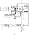
- Fig. 1 is an overall block diagram of a hybrid vehicle (hereinafter referred to as the vehicle) 100.
- vehicle 100 is provided with an engine 1, a first clutch 2, a motor generator (hereinafter referred to as the MG) 3, a first oil pump 4, a second oil pump 5, a second clutch 6, a transmission 7, driving wheels 8, a power source controller 50, and a power train controller 51.
- MG motor generator
- the engine 1 is an internal combustion engine that uses gasoline, diesel fuel or the like as fuel, and its rotation speed, torque and the like are controlled based on a command from the power source controller 50.
- the first clutch 2 is a normal-open hydraulic clutch that is interposed between the engine 1 and the MG 3. Based on a command from the power train controller 51, a state of engagement/release of the first clutch 2 is controlled by hydraulic pressure, whose pressure is adjusted by a hydraulic control valve unit 71 by using discharge pressure from the first oil pump 4 or the second oil pump 5 as original pressure.
- a multi-plate dry clutch is used as the first clutch 2, for example.
- the MG 3 arranged in series with the engine 1, is a synchronous rotary electric machine, in which a permanent magnet is embedded in a rotor and a stator coil is wound around a stator, and serves as a power source of the vehicle 100 together with the engine 1. Based on a command from the power source controller 50, the MG 3 is controlled by application of a three-phase alternating current that is made by an inverter 9. The MG 3 may be operated as an electric motor that is rotatively driven by receiving supply of electric power from a battery 10. When the rotor receives rotational energy from the engine 1 and the driving wheels 8, the MG 3 may function as a power generator that causes electromotive force at both ends of the stator coil, and may charge the battery 10.
- the first oil pump 4 is a vane pump that is operated by transmission of rotation of the MG 3 via a belt 4b.
- the first oil pump 4 sucks hydraulic oil stored in an oil pan 72 of the transmission 7, and supplies hydraulic pressure to the hydraulic control valve unit 71.
- the second oil pump 5 is an electric oil pump that is operated by receiving supply of the electric power from the battery 10. Based on a command from the power train controller 51, the second oil pump 5 is driven when oil quantity is not enough by the first oil pump 4 only. Similarly to the first oil pump 4, the second oil pump 5 sucks the hydraulic oil stored in the oil pan 72 of the transmission 7, and supplies the hydraulic pressure to the hydraulic control valve unit 71.
- the second clutch 6 is interposed between the MG 3 and the transmission 7 and driving wheels 8. Based on a command from the power train controller 51, engagement/release of the second clutch is controlled by the hydraulic pressure, whose pressure is adjusted by the hydraulic control valve unit 71 by using the discharge pressure from the first oil pump 4 or the second oil pump 5 as the original pressure.
- a normal-open multi-plate wet clutch is used as the second clutch 6, for example.
- the transmission 7 is a multi-gear-position transmission with 7 forward gear positions and 1 backward gear position, the multi-gear position transmission being formed by a plurality of planetary gear mechanisms and a plurality of friction elements (a clutch or a brake) for realizing the gear positions. Shift of the transmission 7 is made in such a manner that, by setting a target gear position based on vehicle speed and accelerator opening, the hydraulic pressure, supplied from the hydraulic control valve unit 71 to the plurality of friction elements for realizing the gear positions, is controlled so as to cause a combination of the engaged friction elements to become a combination corresponding to the target gear position.
- a differential 12 is connected to an output shaft of the transmission 7 via a not-illustrated final speed reduction gear mechanism, and the driving wheels 8 are connected to the differential 12 via drive shafts 13.
- the power source controller 50 and the power train controller 51 are connected via a CAN, and are able to deliver various signals via the CAN.
- the signals delivered from the power train controller 51 to the power source controller 50 include a temperature output value TCL2OUT of the second clutch 6, as will be described later.
- TCL2OUT temperature output value
- the power source controller 50 turns a warning lamp 56 on, and makes torque-down control of the engine 1 and the MG 3 when required.
- the power train controller 51 refers to a mode switching map as illustrated in Fig. 2 , and switches between an EV mode and an HEV mode as an operation mode of the vehicle 100.
- the first clutch 2 is released and the vehicle 100 travels by using only the MG 3 as a driving source.
- the EV mode is selected when required driving force is small and a charge amount of the battery 10 is enough.
- the first clutch 2 With the HEV mode, the first clutch 2 is engaged and the vehicle 100 travels by using the engine 1 and the MG 3 as the driving source.
- the HEV mode is selected when the required driving force is large or the charge amount of the battery 10 is not enough.
- a switching line from the EV mode to the HEV mode is set on a higher vehicle speed side and on a larger accelerator opening side, as compared with a switching line from the HEV mode to the EV mode.
- the power train controller 51 makes the WSC control, by which the vehicle 100 is started and stopped while causing the second clutch 6 to slip, in a WSC region as illustrated in Fig. 2 (in a low vehicle speed region where the vehicle speed is VSP1 or less, at the time of start, deceleration and stop, wherein VSP1 is 10km/h, for example).
- the power train controller 51 gradually increases the hydraulic pressure to be supplied to the second clutch 6, and causes the second clutch 6 to slip and to be engaged gradually.
- the power train controller 51 causes the second clutch 6 to be fully engaged, and finishes the WSC control.
- the power train controller 51 gradually decreases the hydraulic pressure to be supplied to the second clutch 6, and causes the second clutch 6 to slip and to be released gradually.
- the power train controller 51 causes the second clutch 6 to be fully released, and finishes the WSC control.
- Fig. 3 is a flowchart illustrating the details of setting processing of the temperature output value TCL2OUT of the second clutch 6, which is executed repeatedly by the power train controller 51.
- the power train controller 51 determines whether a burning history BCOUNT is 0 or not.
- the burning history BCOUNT is a value counting a number of times when a temperature calculation value TCL2CAL of the second clutch 6 exceeds an upper limit temperature HTEMP2 (320°C, for example) by the later-described processing as illustrated in Fig. 4 .
- the upper limit temperature HTEMP2 is an upper limit value of a range of the temperature that the second clutch 6 can maintain without the seizure or the burnout.
- the power train controller 51 determines whether or not the temperature calculation value TCL2CAL of the second clutch 6 is lower than a critical temperature HTEMP1 (560°C, for example).
- the temperature calculation value TCL2CAL of the second clutch 6 can be calculated based on the calculated heating quantity of the second clutch 6 and heat radiation quantity from the second clutch 6 and the like, the heating quantity of the second clutch 6 being calculated based on a rotation speed difference of the second clutch 6 and input torque to the second clutch 6.
- the critical temperature HTEMP1 is the temperature at which the temperature of the second clutch 6 needs to be lowered immediately in order to protect the second clutch 6 from the seizure or the burnout.
- the power train controller 51 determines whether or not a value of a flag STATUS is 0. An initial value of the flag STATUS is 0, and hence the processing proceeds to S4 when the processing is executed for the first time.
- the power train controller 51 determines whether or not the temperature calculation value TCL2CAL of the second clutch 6 is an upper limit temperature HTEMP2 or more. When the temperature calculation value TCL2CAL of the second clutch 6 is the upper limit temperature HTEMP2 or higher, the processing proceeds to S5.
- the power train controller 51 starts count of a first timer.
- the first timer measures a period of time from when the temperature calculation value TCL2CAL of the second clutch 6 becomes the upper limit temperature HTEMP2 or more and during when the state continues.
- the power train controller 51 determines whether or not the value of the first timer exceeds a predetermined period of time T1 (five seconds, for example). When the value of the first timer does not exceed the predetermined period of time T1, the processing proceeds to S8, where the power train controller 51 outputs, as the temperature output value TCL2OUT of the second clutch 6, a constant value that is by a few degrees lower than the upper limit temperature HTEMP2 (315°C, for example) to the power source controller 50.
- the processing proceeds to S7, where the power train controller 51 sets the flag STATUS as 1 and outputs, as the temperature output value TCL2OUT of the second clutch 6, the temperature calculation value TCL2CAL of the second clutch 6 to the power source controller 50.
- the processing proceeds to S9, where the flag STATUS is set as 1. Then, in S10, the power train controller 51 outputs, as the temperature output value TCL2OUT of the second clutch 6, the temperature calculation value TCL2CAL of the second clutch 6 to the power source controller 50.
- the processing proceeds to S10, where the power train controller 51 outputs, as the temperature output value TCL2OUT of the second clutch 6, the temperature calculation value TCL2CAL of the second clutch 6 to the power source controller 50.
- the temperature calculation value TCL2CAL of the second clutch 6 is outputted, as the temperature output value TCL2OUT of the second clutch 6, to the power source controller 50 in the case:
- the constant value (pseudo temperature) that is lower than the upper limit temperature HTEMP2 is outputted to the power source controller 50 as the temperature output value TCL2OUT of the second clutch 6, instead of the temperature calculation value TCL2CAL of the second clutch 6.
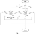
- Fig. 4 is a flowchart illustrating the details of updating processing of the burning history BCOUNT, which is executed repeatedly by the power train controller 51.
- the power train controller 51 determines whether a flag F is 1 or not. An initial value of the flag F is 0, and hence the processing proceeds to S22 when the processing is executed for the first time.
- the power train controller 51 determines whether or not the temperature calculation value TCL2CAL of the second clutch 6 is higher than the upper limit temperature HTEMP2. When it is determined that the temperature calculation value TCL2CAL of the second clutch 6 is higher than the upper limit temperature HTEMP2, the processing proceeds to S23, where the flag F is set as 1.
- the power train controller 51 determines whether or not the temperature calculation value TCL2CAL of the second clutch 6 is lower than a burning completion determination temperature HTEMP3 (300°C, for example) that is sufficiently lower than the upper limit temperature HTEMP2.
- HTEMP3 300°C, for example
- the processing proceeds to S25, where 1 is added to the burning history BCOUNT and the flag F is set as 0.
- Fig. 5 is a flowchart illustrating the details of protecting processing of the second clutch 6, which is executed repeatedly by the power source controller 50.
- the power source controller 50 determines whether or not the temperature output value TCL2OUT of the second clutch 6, received from the power train controller 51, exceeds the critical temperature HTEMP1. When the temperature output value TCL2OUT of the second clutch 6 exceeds the critical temperature HTEMP1, the processing proceeds to S32, where the power source controller 50 turns the warning lamp 56 on and makes torque-down control of the engine 1 and the MG 3.
- the power source controller 50 determines whether or not the temperature output value TCL2OUT of the second clutch 6 exceeds the upper limit temperature HTEMP2. When the temperature output value TCL2OUT of the second clutch 6 exceeds the upper limit temperature HTEMP2, the processing proceeds to S34.
- the power source controller 50 starts count of a second timer.
- the second timer measures a period of time from when the temperature output value TCL2OUT of the second clutch 6 exceeds the upper limit temperature HTEMP2 and during when the state continues.
- the power source controller 50 determines whether or not the second timer exceeds a predetermined period of time T2 (five seconds, for example). When the second timer exceeds the predetermined period of time T2, the processing proceeds to S36, where the power source controller 50 turns the warning lamp 56 on. When the second timer does not exceed the predetermined period of time T2, the processing proceeds to S37 and the power source controller 50 does not turn the warning lamp 56 on.
- a predetermined period of time T2 five seconds, for example.
- the warning lamp 56 is turned on in the case:
- the warning lamp 56 is turned on when the temperature output value TCL2OUT of the second clutch 6, outputted from the power train controller 51 to the power source controller 50, exceeds the upper limit temperature HTEMP2, and the state continues for the predetermined period of time T2 (S35 ⁇ S36 in Fig. 5 ).
- the temperature calculation value TCL2CAL of the second clutch 6 exceeds the upper limit temperature HTEMP2 for the first time (YES in S1 of Fig. 3 )
- the temperature calculation value TCL2CAL of the second clutch 6 is not outputted as the temperature output value TCL2OUT of the second clutch 6 as it is, and the constant value (pseudo temperature) that is lower than the upper limit temperature HTEMP2 is outputted as the temperature output value TCL2OUT of the second clutch 6, during the predetermined period of time T1 (S6 ⁇ S8 in Fig. 3 ).
- the temperature calculation value TCL2CAL of the second clutch 6 exceeds the upper limit temperature HTEMP2 for the first time until when the predetermined period of time T1 elapses, the temperature output value TCL2OUT of the second clutch 6 continues to be lower than the upper limit temperature HTEMP2, and the warning lamp 56 does not turn on (S33 ⁇ S37 in Fig. 5 ).
- the warning lamp 56 is turned on for the first time when the predetermined period of time T1 elapses and the temperature calculation value TCL2CAL of the second clutch 6 is outputted as the temperature output value TCL2OUT of the second clutch 6 (S6 ⁇ S7 in Fig. 3 ), and when the temperature output value TCL2OUT of the second clutch 6 continues to be higher than the upper limit temperature HTEMP2 for the predetermined period of time T2 (S35 ⁇ S36 in Fig. 5 ).
- the temperature calculation value TCL2CAL of the second clutch 6 exceeds the upper limit temperature HTEMP2 for the second or the subsequent time, (NO in S1 of Fig. 3 ), the temperature calculation value TCL2CAL of the second clutch 6 is outputted as the temperature output value TCL2OUT of the second clutch 6 (S10 in Fig. 3 ). Therefore, the warning lamp 56 is turned on (S35 ⁇ S36 in Fig. 5 ) when the temperature calculation value TCL2CAL of the second clutch 6 exceeds the upper limit temperature HTEMP2 and simultaneously the temperature output value TCL2OUT of the second clutch 6 exceeds the upper limit temperature HTEMP2, and when this state is continued for the predetermined period of time T2.
- the period of time from when the temperature calculation value TCL2CAL of the second clutch 6 exceeds the upper limit temperature HTEMP2 until when the warning lamp 56 is turned on is longer by the predetermined period of time T1 in the case when the temperature calculation value TCL2CAL of the second clutch 6 exceeds the upper limit temperature HTEMP2 for the first time, than the case of the second time.
- Heat resistance of the second clutch 6 differs depending on whether or not the second clutch 6 experiences the burning exceeding the upper limit temperature HTEMP2, and the heat resistance is high when the second clutch 6 has no experience of the burning.
- the period of time until the warning lamp 56 is turned on is made longer when the temperature calculation value TCL2CAL of the second clutch 6 exceeds the upper limit temperature HTEMP2 for the first time, it is possible to call attention to the driver at more appropriate timing, corresponding to the heat resistance of the second clutch 6.
- the warning lamp 56 is turned on to inform the driver that the temperature of the second clutch 6 becomes high, but other methods, such as voice, an alarm, a message on a display, and the like may be used.
- the friction element for monitoring the temperature is not limited to the second clutch 6, and a brake or a clutch that is provided on another position, or a brake or a clutch that does not make the WSC control may be employed.
Landscapes
- Engineering & Computer Science (AREA)
- General Engineering & Computer Science (AREA)
- Mechanical Engineering (AREA)
- Physics & Mathematics (AREA)
- Fluid Mechanics (AREA)
- Oil, Petroleum & Natural Gas (AREA)
- Hydraulic Clutches, Magnetic Clutches, Fluid Clutches, And Fluid Joints (AREA)
- Control Of Transmission Device (AREA)
- Mechanical Operated Clutches (AREA)
- Braking Arrangements (AREA)
- Valves And Accessory Devices For Braking Systems (AREA)
Abstract
Description
- The present invention relates to a technique of issuing a warning depending on temperature of a friction element.
- When temperature of a friction element that is used for a power train, such as a clutch, a brake, or the like, becomes high, seizure or burnout is caused. In
JP2008-57670A - However, heat resistance of the friction element differs depending on whether or not the friction element experiences burning exceeding the upper limit temperature, and the heat resistance is higher when the friction element has no experience of burning than when the friction element has the experience of burning.
- When the same upper limit temperature as that of the friction element having the experience of burning is used for the friction element without the experience of burning, a warning is excessively issued by the warning lamp when the friction element does not have the experience of burning, thus giving insecure feelings to a driver.
- It is an object of the present invention to appropriately issue a warning when the temperature of the friction element becomes high.
- According to an aspect of the present invention, a temperature warning device of a friction element for issuing a warning depending on temperature of the friction element arranged between a power source and a driving wheel, is provided. The temperature warning device comprises warning issuing means adapted to issue the warning when the temperature of the friction element exceeds upper limit temperature, and warning issuing timing adjusting means adapted to make a period of time, from when the temperature of the friction element exceeds the upper limit temperature until when the warning issuing means issues the warning, longer when the temperature of the friction element exceeds the upper limit temperature for a first time, than when the temperature of the friction element exceeds the upper limit temperature for a second or subsequent time.
- According to another aspect of the present invention, a corresponding temperature warning method of a friction element is provided.
- According to these aspects, when the temperature of the friction element exceeds the upper limit temperature for a first time, the period of time until the warning is issued is made longer. Therefore, it becomes possible to call attention to the driver at more appropriate timing, corresponding to the heat resistance of the friction element.
-
-
Fig. 1 is a schematic block diagram of a hybrid vehicle; -
Fig. 2 is an example of a mode switching map; -
Fig. 3 is a flowchart illustrating details of setting processing of a temperature output value of a second clutch; -
Fig. 4 is a flowchart illustrating details of updating processing of a burning history; and -
Fig. 5 is a flowchart illustrating details of protecting processing of the second clutch. - An embodiment of the present invention will be explained with reference to the attached drawings.
-
Fig. 1 is an overall block diagram of a hybrid vehicle (hereinafter referred to as the vehicle) 100. Thevehicle 100 is provided with anengine 1, afirst clutch 2, a motor generator (hereinafter referred to as the MG) 3, a first oil pump 4, asecond oil pump 5, a second clutch 6, atransmission 7,driving wheels 8, apower source controller 50, and apower train controller 51. - The
engine 1 is an internal combustion engine that uses gasoline, diesel fuel or the like as fuel, and its rotation speed, torque and the like are controlled based on a command from thepower source controller 50. - The
first clutch 2 is a normal-open hydraulic clutch that is interposed between theengine 1 and the MG 3. Based on a command from thepower train controller 51, a state of engagement/release of thefirst clutch 2 is controlled by hydraulic pressure, whose pressure is adjusted by a hydrauliccontrol valve unit 71 by using discharge pressure from the first oil pump 4 or thesecond oil pump 5 as original pressure. A multi-plate dry clutch is used as thefirst clutch 2, for example. - The MG 3, arranged in series with the
engine 1, is a synchronous rotary electric machine, in which a permanent magnet is embedded in a rotor and a stator coil is wound around a stator, and serves as a power source of thevehicle 100 together with theengine 1. Based on a command from thepower source controller 50, the MG 3 is controlled by application of a three-phase alternating current that is made by aninverter 9. The MG 3 may be operated as an electric motor that is rotatively driven by receiving supply of electric power from abattery 10. When the rotor receives rotational energy from theengine 1 and thedriving wheels 8, the MG 3 may function as a power generator that causes electromotive force at both ends of the stator coil, and may charge thebattery 10. - The first oil pump 4 is a vane pump that is operated by transmission of rotation of the MG 3 via a
belt 4b. The first oil pump 4 sucks hydraulic oil stored in anoil pan 72 of thetransmission 7, and supplies hydraulic pressure to the hydrauliccontrol valve unit 71. - The
second oil pump 5 is an electric oil pump that is operated by receiving supply of the electric power from thebattery 10. Based on a command from thepower train controller 51, thesecond oil pump 5 is driven when oil quantity is not enough by the first oil pump 4 only. Similarly to the first oil pump 4, thesecond oil pump 5 sucks the hydraulic oil stored in theoil pan 72 of thetransmission 7, and supplies the hydraulic pressure to the hydrauliccontrol valve unit 71. - The second clutch 6 is interposed between the MG 3 and the
transmission 7 anddriving wheels 8. Based on a command from thepower train controller 51, engagement/release of the second clutch is controlled by the hydraulic pressure, whose pressure is adjusted by the hydrauliccontrol valve unit 71 by using the discharge pressure from the first oil pump 4 or thesecond oil pump 5 as the original pressure. A normal-open multi-plate wet clutch is used as the second clutch 6, for example. - The
transmission 7 is a multi-gear-position transmission with 7 forward gear positions and 1 backward gear position, the multi-gear position transmission being formed by a plurality of planetary gear mechanisms and a plurality of friction elements (a clutch or a brake) for realizing the gear positions. Shift of thetransmission 7 is made in such a manner that, by setting a target gear position based on vehicle speed and accelerator opening, the hydraulic pressure, supplied from the hydrauliccontrol valve unit 71 to the plurality of friction elements for realizing the gear positions, is controlled so as to cause a combination of the engaged friction elements to become a combination corresponding to the target gear position. - A
differential 12 is connected to an output shaft of thetransmission 7 via a not-illustrated final speed reduction gear mechanism, and thedriving wheels 8 are connected to thedifferential 12 viadrive shafts 13. - The
power source controller 50 and thepower train controller 51 are connected via a CAN, and are able to deliver various signals via the CAN. The signals delivered from thepower train controller 51 to thepower source controller 50 include a temperature output value TCL2OUT of the second clutch 6, as will be described later. When the temperature of the second clutch 6 becomes high, thepower source controller 50 turns awarning lamp 56 on, and makes torque-down control of theengine 1 and the MG 3 when required. - Signals from a
rotation speed sensor 52 that detects output rotation speed of the second clutch 6 (= input rotation speed of the transmission 7), an accelerator opening sensor 53 that detects accelerator opening, an inhibitor switch 54 that detects a select position of the transmission 7 (state of a select lever or a select switch that switches between forward, backward, neutral and parking), avehicle speed sensor 55 that detects the vehicle speed and the like are inputted to thepower train controller 51. Based on these inputted signals, thepower train controller 51 makes shift control of thetransmission 7, later-described mode switching control, and WSC control. - In the mode switching control, the
power train controller 51 refers to a mode switching map as illustrated inFig. 2 , and switches between an EV mode and an HEV mode as an operation mode of thevehicle 100. - With the EV mode, the
first clutch 2 is released and thevehicle 100 travels by using only the MG 3 as a driving source. The EV mode is selected when required driving force is small and a charge amount of thebattery 10 is enough. - With the HEV mode, the
first clutch 2 is engaged and thevehicle 100 travels by using theengine 1 and the MG 3 as the driving source. The HEV mode is selected when the required driving force is large or the charge amount of thebattery 10 is not enough. - In order to prevent hunting at the time of switching between the EV mode and the HEV mode, a switching line from the EV mode to the HEV mode is set on a higher vehicle speed side and on a larger accelerator opening side, as compared with a switching line from the HEV mode to the EV mode.
- As the
vehicle 100 is not provided with a torque converter, thepower train controller 51 makes the WSC control, by which thevehicle 100 is started and stopped while causing the second clutch 6 to slip, in a WSC region as illustrated inFig. 2 (in a low vehicle speed region where the vehicle speed is VSP1 or less, at the time of start, deceleration and stop, wherein VSP1 is 10km/h, for example). - Specifically, when the
vehicle 100 starts by switching the select position of thetransmission 7 from a non-traveling position (N, P or the like) to a traveling position (D, R or the like), thepower train controller 51 gradually increases the hydraulic pressure to be supplied to the second clutch 6, and causes the second clutch 6 to slip and to be engaged gradually. When the vehicle speed reaches VSP1, thepower train controller 51 causes the second clutch 6 to be fully engaged, and finishes the WSC control. - When the
vehicle 100 travels while the select position of thetransmission 7 is in the traveling position (D, R or the like) and when thevehicle 100 decelerates and its vehicle speed decreases to VSP1, thepower train controller 51 gradually decreases the hydraulic pressure to be supplied to the second clutch 6, and causes the second clutch 6 to slip and to be released gradually. When thevehicle 100 stops, thepower train controller 51 causes the second clutch 6 to be fully released, and finishes the WSC control. - As the second clutch 6 is caused to slip in the above-described WSC control, heating quantity of the second clutch 6 increases and the temperature of the second clutch 6 (the temperature of a facing) increases. Especially when the WSC control is made on a climbing road, the temperature rise of the second clutch 6 becomes remarkable.
- For this reason, it is necessary to monitor the temperature of the second clutch 6 and, when the temperature of the second clutch 6 becomes high, to call attention to a driver by turning the
warning lamp 56 on, and to make the torque-down control of theengine 1 and theMG 3 when necessary, so as to protect the second clutch 6 from seizure or burnout. - In connection with the above, control made by the
power source controller 50 and thepower train controller 51 will be explained below. -
Fig. 3 is a flowchart illustrating the details of setting processing of the temperature output value TCL2OUT of the second clutch 6, which is executed repeatedly by thepower train controller 51. - Specifically, in S1, the
power train controller 51 determines whether a burning history BCOUNT is 0 or not. The burning history BCOUNT is a value counting a number of times when a temperature calculation value TCL2CAL of the second clutch 6 exceeds an upper limit temperature HTEMP2 (320°C, for example) by the later-described processing as illustrated inFig. 4 . The upper limit temperature HTEMP2 is an upper limit value of a range of the temperature that the second clutch 6 can maintain without the seizure or the burnout. Even though the seizure or the burnout is not caused immediately when the temperature of the second clutch 6 becomes the upper limit temperature HTEMP2 or more, the seizure or the burnout is caused when the temperature is equal to or more than the upper limit temperature HTEMP2 for a continuous period of time. When 0 is stored in the burning history BCOUNT, the processing proceeds to S2. - In S2, the
power train controller 51 determines whether or not the temperature calculation value TCL2CAL of the second clutch 6 is lower than a critical temperature HTEMP1 (560°C, for example). The temperature calculation value TCL2CAL of the second clutch 6 can be calculated based on the calculated heating quantity of the second clutch 6 and heat radiation quantity from the second clutch 6 and the like, the heating quantity of the second clutch 6 being calculated based on a rotation speed difference of the second clutch 6 and input torque to the second clutch 6. The critical temperature HTEMP1 is the temperature at which the temperature of the second clutch 6 needs to be lowered immediately in order to protect the second clutch 6 from the seizure or the burnout. When the temperature calculation value TCL2CAL of the second clutch 6 is lower than the critical temperature HTEMP1, the processing proceeds to S3. - In S3, the
power train controller 51 determines whether or not a value of a flag STATUS is 0. An initial value of the flag STATUS is 0, and hence the processing proceeds to S4 when the processing is executed for the first time. - In S4, the
power train controller 51 determines whether or not the temperature calculation value TCL2CAL of the second clutch 6 is an upper limit temperature HTEMP2 or more. When the temperature calculation value TCL2CAL of the second clutch 6 is the upper limit temperature HTEMP2 or higher, the processing proceeds to S5. - In S5, the
power train controller 51 starts count of a first timer. The first timer measures a period of time from when the temperature calculation value TCL2CAL of the second clutch 6 becomes the upper limit temperature HTEMP2 or more and during when the state continues. - In S6, the
power train controller 51 determines whether or not the value of the first timer exceeds a predetermined period of time T1 (five seconds, for example). When the value of the first timer does not exceed the predetermined period of time T1, the processing proceeds to S8, where thepower train controller 51 outputs, as the temperature output value TCL2OUT of the second clutch 6, a constant value that is by a few degrees lower than the upper limit temperature HTEMP2 (315°C, for example) to thepower source controller 50. On the other hand, when the value of the first timer exceeds the predetermined period of time T1, the processing proceeds to S7, where thepower train controller 51 sets the flag STATUS as 1 and outputs, as the temperature output value TCL2OUT of the second clutch 6, the temperature calculation value TCL2CAL of the second clutch 6 to thepower source controller 50. - Meanwhile, when it is determined that the burning history BCOUTURE is not 0 in S1, the processing proceeds to S9, where the flag STATUS is set as 1. Then, in S10, the
power train controller 51 outputs, as the temperature output value TCL2OUT of the second clutch 6, the temperature calculation value TCL2CAL of the second clutch 6 to thepower source controller 50. - Further, when it is determined that the flag STATUS is not 0 in S3, and when it is determined that the temperature calculation value TCL2CAL of the second clutch 6 is lower than the upper limit temperature HTEMP2 in S4, the processing proceeds to S10, where the
power train controller 51 outputs, as the temperature output value TCL2OUT of the second clutch 6, the temperature calculation value TCL2CAL of the second clutch 6 to thepower source controller 50. - Therefore, according to the above-described processing, the temperature calculation value TCL2CAL of the second clutch 6 is outputted, as the temperature output value TCL2OUT of the second clutch 6, to the
power source controller 50 in the case: - when the temperature calculation value TCL2CAL of the second clutch 6 is higher than the critical temperature HTEMP1;
- when the temperature calculation value TCL2CAL of the second clutch 6 is lower than the upper limit temperature HTEMP2; or
- when the temperature calculation value TCL2CAL of the second clutch 6 exceeds the upper limit temperature HTEMP2 and the predetermined period of time T1 has elapsed from when the temperature calculation value TCL2CAL of the second clutch 6 exceeds the upper limit temperature HTEMP2.
- Meanwhile, during the period from when the temperature calculation value TCL2CAL of the second clutch 6 exceeds the upper limit temperature HTEMP2 until when the predetermined period of time T1 has elapsed, the constant value (pseudo temperature) that is lower than the upper limit temperature HTEMP2 is outputted to the
power source controller 50 as the temperature output value TCL2OUT of the second clutch 6, instead of the temperature calculation value TCL2CAL of the second clutch 6. -
Fig. 4 is a flowchart illustrating the details of updating processing of the burning history BCOUNT, which is executed repeatedly by thepower train controller 51. - Specifically, in S21, the
power train controller 51 determines whether a flag F is 1 or not. An initial value of the flag F is 0, and hence the processing proceeds to S22 when the processing is executed for the first time. - In S22, the
power train controller 51 determines whether or not the temperature calculation value TCL2CAL of the second clutch 6 is higher than the upper limit temperature HTEMP2. When it is determined that the temperature calculation value TCL2CAL of the second clutch 6 is higher than the upper limit temperature HTEMP2, the processing proceeds to S23, where the flag F is set as 1. - When the flag F is set as 1, the processing proceeds from S21 to S24 when S21 is executed for the next time.
- In S24, the
power train controller 51 determines whether or not the temperature calculation value TCL2CAL of the second clutch 6 is lower than a burning completion determination temperature HTEMP3 (300°C, for example) that is sufficiently lower than the upper limit temperature HTEMP2. When it is determined that the temperature calculation value TCL2CAL of the second clutch 6 is lower than the burning completion determination temperature HTEMP3, the processing proceeds to S25, where 1 is added to the burning history BCOUNT and the flag F is set as 0. - Therefore, according to the above-described processing, 1 is added to the burning history BCOUNT at timing when the temperature calculation value TCL2CAL of the second clutch 6 exceeds the upper limit temperature HTEMP2 and thereafter the temperature calculation value TCL2CAL of the second clutch 6 becomes lower than the burning completion determination temperature HTEMP3.
-
Fig. 5 is a flowchart illustrating the details of protecting processing of the second clutch 6, which is executed repeatedly by thepower source controller 50. - Specifically, in S31, the
power source controller 50 determines whether or not the temperature output value TCL2OUT of the second clutch 6, received from thepower train controller 51, exceeds the critical temperature HTEMP1. When the temperature output value TCL2OUT of the second clutch 6 exceeds the critical temperature HTEMP1, the processing proceeds to S32, where thepower source controller 50 turns the warninglamp 56 on and makes torque-down control of theengine 1 and theMG 3. - When the temperature output value TCL2OUT of the second clutch 6 does not exceed the critical temperature HTEMP1, the processing proceeds to S33.
- In S33, the
power source controller 50 determines whether or not the temperature output value TCL2OUT of the second clutch 6 exceeds the upper limit temperature HTEMP2. When the temperature output value TCL2OUT of the second clutch 6 exceeds the upper limit temperature HTEMP2, the processing proceeds to S34. - In S34, the
power source controller 50 starts count of a second timer. The second timer measures a period of time from when the temperature output value TCL2OUT of the second clutch 6 exceeds the upper limit temperature HTEMP2 and during when the state continues. - In S35, the
power source controller 50 determines whether or not the second timer exceeds a predetermined period of time T2 (five seconds, for example). When the second timer exceeds the predetermined period of time T2, the processing proceeds to S36, where thepower source controller 50 turns the warninglamp 56 on. When the second timer does not exceed the predetermined period of time T2, the processing proceeds to S37 and thepower source controller 50 does not turn thewarning lamp 56 on. - Therefore, according to the above-described processing, the warning
lamp 56 is turned on in the case: - when the temperature output value TCL2OUT of the second clutch 6 exceeds the critical temperature HTEMP1; or
- when the temperature output value TCL2OUT of the second clutch 6 exceeds the upper limit temperature HTEMP2 and this state is continued for the predetermined period of time T2.
- Next, an explanation will be given to operations and effects of the control executed by the
power source controller 50 and thepower train controller 51, as illustrated inFig. 3 to Fig. 5 . - According to the above-described processing, the warning
lamp 56 is turned on when the temperature output value TCL2OUT of the second clutch 6, outputted from thepower train controller 51 to thepower source controller 50, exceeds the upper limit temperature HTEMP2, and the state continues for the predetermined period of time T2 (S35 → S36 inFig. 5 ). - However, when the temperature calculation value TCL2CAL of the second clutch 6 exceeds the upper limit temperature HTEMP2 for the first time (YES in S1 of
Fig. 3 ), the temperature calculation value TCL2CAL of the second clutch 6 is not outputted as the temperature output value TCL2OUT of the second clutch 6 as it is, and the constant value (pseudo temperature) that is lower than the upper limit temperature HTEMP2 is outputted as the temperature output value TCL2OUT of the second clutch 6, during the predetermined period of time T1 (S6 → S8 inFig. 3 ). - Therefore, from when the temperature calculation value TCL2CAL of the second clutch 6 exceeds the upper limit temperature HTEMP2 for the first time until when the predetermined period of time T1 elapses, the temperature output value TCL2OUT of the second clutch 6 continues to be lower than the upper limit temperature HTEMP2, and the warning
lamp 56 does not turn on (S33 → S37 inFig. 5 ). - The warning
lamp 56 is turned on for the first time when the predetermined period of time T1 elapses and the temperature calculation value TCL2CAL of the second clutch 6 is outputted as the temperature output value TCL2OUT of the second clutch 6 (S6 → S7 inFig. 3 ), and when the temperature output value TCL2OUT of the second clutch 6 continues to be higher than the upper limit temperature HTEMP2 for the predetermined period of time T2 (S35 → S36 inFig. 5 ). - Meanwhile, when the temperature calculation value TCL2CAL of the second clutch 6 exceeds the upper limit temperature HTEMP2 for the second or the subsequent time, (NO in S1 of
Fig. 3 ), the temperature calculation value TCL2CAL of the second clutch 6 is outputted as the temperature output value TCL2OUT of the second clutch 6 (S10 inFig. 3 ). Therefore, the warninglamp 56 is turned on (S35 → S36 inFig. 5 ) when the temperature calculation value TCL2CAL of the second clutch 6 exceeds the upper limit temperature HTEMP2 and simultaneously the temperature output value TCL2OUT of the second clutch 6 exceeds the upper limit temperature HTEMP2, and when this state is continued for the predetermined period of time T2. - Therefore, the period of time from when the temperature calculation value TCL2CAL of the second clutch 6 exceeds the upper limit temperature HTEMP2 until when the warning
lamp 56 is turned on is longer by the predetermined period of time T1 in the case when the temperature calculation value TCL2CAL of the second clutch 6 exceeds the upper limit temperature HTEMP2 for the first time, than the case of the second time. - Heat resistance of the second clutch 6 differs depending on whether or not the second clutch 6 experiences the burning exceeding the upper limit temperature HTEMP2, and the heat resistance is high when the second clutch 6 has no experience of the burning. When the period of time until the warning
lamp 56 is turned on is made longer when the temperature calculation value TCL2CAL of the second clutch 6 exceeds the upper limit temperature HTEMP2 for the first time, it is possible to call attention to the driver at more appropriate timing, corresponding to the heat resistance of the second clutch 6. - As a specific method for causing the period of time until the warning
lamp 56 is turned on to become longer only when the temperature calculation value TCL2CAL of the second clutch 6 exceeds the upper limit temperature HTEMP2 for the first time, such a method is employed that the constant value (pseudo temperature), lower than the upper limit temperature HTEMP2, is outputted from thepower train controller 51 to thepower source controller 50 during the predetermined period of time T1 (S6 → S8 inFig. 3 ), and thepower source controller 50 is made to recognize that the temperature of the second clutch 6 is lower than the upper limit temperature HTEMP2 during this period. - Thus, the above-described operations can be realized by changing the control details on the
power train controller 51 side only (Fig. 3 ), without changing the control details on thepower source controller 50 side (Fig. 5 ). This method is effective especially when there are restrictions in changing the control details on thepower source controller 50 side. - When it is possible to change the control details on the
power source controller 50 side, similar control can be made by changing the predetermined period of time T2 depending on whether or not the temperature calculation value TCL2CAL of the second clutch 6 exceeds the upper limit temperature HTEMP2 for the first time. - Although the embodiment of the present invention has been explained thus far, the above-described embodiment is only a part of application examples of the present invention, and is not intended to limit the technical scope of the present invention to the concrete structure of the above-described embodiment.
- According to the above-described embodiment, for example, the warning
lamp 56 is turned on to inform the driver that the temperature of the second clutch 6 becomes high, but other methods, such as voice, an alarm, a message on a display, and the like may be used. - Further, the friction element for monitoring the temperature is not limited to the second clutch 6, and a brake or a clutch that is provided on another position, or a brake or a clutch that does not make the WSC control may be employed.
- The present application claims a priority of Japanese Patent Application No.
2013-82202
Claims (3)
- A temperature warning device of a friction element for issuing a warning depending on temperature of the friction element arranged between a power source and a driving wheel, comprising:warning issuing means adapted to issue the warning when the temperature of the friction element exceeds upper limit temperature; andwarning issuing timing adjusting means adapted to make a period of time, from when the temperature of the friction element exceeds the upper limit temperature until when the warning issuing means issues the warning, longer when the temperature of the friction element exceeds the upper limit temperature for a first time, than when the temperature of the friction element exceeds the upper limit temperature for a second or subsequent time.
- The temperature warning device of the friction element according to claim 1, further comprising
friction element temperature calculating and outputting means adapted to calculate the temperature of the friction element on the basis of an operation state of the friction element, and output a calculation value of the temperature of the friction element to the warning issuing means,
wherein the warning issuing timing adjusting means is formed by the friction element temperature calculating and outputting means outputting, for a predetermined period of time, a value lower than the upper limit temperature, instead of the calculation value of the temperature of the friction element, to the warning issuing means, when the calculation value of the temperature of the friction element exceeds the upper limit temperature for a first time. - A temperature warning method of a friction element for issuing a warning depending on temperature of the friction element arranged between a power source and a driving wheel, comprising:issuing the warning when the temperature of the friction element exceeds upper limit temperature; andmaking a period of time, from when the temperature of the friction element exceeds the upper limit temperature until when the warning is issued, longer when the temperature of the friction element exceeds the upper limit temperature for a first time, than when the temperature of the friction element exceeds the upper limit temperature for a second or subsequent time.
Applications Claiming Priority (2)
| Application Number | Priority Date | Filing Date | Title |
|---|---|---|---|
| JP2013082202 | 2013-04-10 | ||
| PCT/JP2014/053133 WO2014167893A1 (en) | 2013-04-10 | 2014-02-12 | Friction element temperature warning device and temperature warning method |
Publications (3)
| Publication Number | Publication Date |
|---|---|
| EP2985483A1 true EP2985483A1 (en) | 2016-02-17 |
| EP2985483A4 EP2985483A4 (en) | 2017-04-19 |
| EP2985483B1 EP2985483B1 (en) | 2020-08-26 |
Family
ID=51689309
Family Applications (1)
| Application Number | Title | Priority Date | Filing Date |
|---|---|---|---|
| EP14783480.8A Active EP2985483B1 (en) | 2013-04-10 | 2014-02-12 | Friction element temperature warning device and temperature warning method |
Country Status (8)
| Country | Link |
|---|---|
| US (1) | US9897202B2 (en) |
| EP (1) | EP2985483B1 (en) |
| JP (1) | JP6204457B2 (en) |
| CN (1) | CN105121888B (en) |
| MX (1) | MX364141B (en) |
| MY (1) | MY179773A (en) |
| RU (1) | RU2646700C2 (en) |
| WO (1) | WO2014167893A1 (en) |
Families Citing this family (7)
| Publication number | Priority date | Publication date | Assignee | Title |
|---|---|---|---|---|
| JP6493073B2 (en) * | 2015-07-31 | 2019-04-03 | 日産自動車株式会社 | Clutch overheat prevention device for hybrid vehicle |
| DE102016211962A1 (en) * | 2016-06-30 | 2018-01-04 | Zf Friedrichshafen Ag | Method for monitoring a friction clutch having at least two adjacent clutch plates |
| US10269249B2 (en) * | 2017-04-14 | 2019-04-23 | Shimano Inc. | Bicycle notification device including attaching portion, transmitter and power generator |
| US11400937B2 (en) * | 2018-08-30 | 2022-08-02 | Volvo Truck Corporation | Method for controlling a driveline of a vehicle |
| US11400938B2 (en) * | 2018-09-14 | 2022-08-02 | Volvo Truck Corporation | Method for controlling a drivline of a vehicle |
| US11346408B2 (en) * | 2019-04-04 | 2022-05-31 | Eaton Cummins Automated Transmission Tech., Llc | Virtual clutch temperature gauge |
| CN114509257B (en) * | 2021-12-27 | 2023-08-15 | 东风汽车集团股份有限公司 | Testing device and evaluating method for anti-ablation performance of clutch |
Family Cites Families (17)
| Publication number | Priority date | Publication date | Assignee | Title |
|---|---|---|---|---|
| JPS63126647U (en) * | 1987-02-13 | 1988-08-18 | ||
| US5218836A (en) * | 1992-06-11 | 1993-06-15 | Eaton Corporation | Measuring evaporator load in an automotive air conditioning system for compressor clutch control using evaporator inlet temperature |
| US5857162A (en) * | 1995-06-30 | 1999-01-05 | General Motors Corporation | Automatic transmission hot mode management |
| US10185455B2 (en) * | 2012-10-04 | 2019-01-22 | Zonar Systems, Inc. | Mobile computing device for fleet telematics |
| JP4015451B2 (en) * | 2002-03-26 | 2007-11-28 | ボッシュ株式会社 | Control device for vehicle drive train |
| JP4736950B2 (en) * | 2006-05-24 | 2011-07-27 | トヨタ自動車株式会社 | VEHICLE POWER DEVICE AND CONTROL DEVICE THEREOF |
| JP2008057670A (en) * | 2006-08-31 | 2008-03-13 | F C C:Kk | Heat generation amount estimation device for clutch |
| RU2448007C2 (en) * | 2006-09-18 | 2012-04-20 | Вольво Ластвагнар Аб | Method of clutch protection |
| JP5232441B2 (en) * | 2007-10-30 | 2013-07-10 | 三菱重工業株式会社 | Clutch device alarm device |
| JP5262197B2 (en) * | 2008-03-10 | 2013-08-14 | 日産自動車株式会社 | Control device for hybrid vehicle |
| KR101417085B1 (en) * | 2008-07-08 | 2014-07-08 | 현대자동차주식회사 | How to control the amount of oil in the engine clutch |
| CN102905929B (en) * | 2010-07-12 | 2015-06-17 | 本田技研工业株式会社 | Control device and control method for hybrid vehicle |
| JP5614236B2 (en) * | 2010-10-22 | 2014-10-29 | 日産自動車株式会社 | Control device for hybrid vehicle |
| WO2012142277A1 (en) | 2011-04-12 | 2012-10-18 | Chrysler Group Llc | Method for determining wet clutch temperature |
| US20140195310A1 (en) * | 2012-10-04 | 2014-07-10 | Zonar Systems, Inc. | Virtual trainer for in vehicle driver coaching and to collect metrics to improve driver performance |
| GB2509934B (en) * | 2013-01-17 | 2016-01-06 | Jaguar Land Rover Ltd | Control system and method |
| DE102013219180A1 (en) * | 2013-09-24 | 2015-03-26 | Voith Patent Gmbh | Method for operating a drive train with a hydrodynamic coupling |
-
2014
- 2014-02-12 WO PCT/JP2014/053133 patent/WO2014167893A1/en not_active Ceased
- 2014-02-12 MY MYPI2015703560A patent/MY179773A/en unknown
- 2014-02-12 RU RU2015147852A patent/RU2646700C2/en active
- 2014-02-12 MX MX2015014183A patent/MX364141B/en active IP Right Grant
- 2014-02-12 EP EP14783480.8A patent/EP2985483B1/en active Active
- 2014-02-12 US US14/783,445 patent/US9897202B2/en active Active
- 2014-02-12 JP JP2015511143A patent/JP6204457B2/en active Active
- 2014-02-12 CN CN201480020432.7A patent/CN105121888B/en active Active
Non-Patent Citations (1)
| Title |
|---|
| See references of WO2014167893A1 * |
Also Published As
| Publication number | Publication date |
|---|---|
| RU2015147852A (en) | 2017-05-16 |
| CN105121888B (en) | 2017-07-14 |
| WO2014167893A1 (en) | 2014-10-16 |
| US20160076644A1 (en) | 2016-03-17 |
| JPWO2014167893A1 (en) | 2017-02-16 |
| MY179773A (en) | 2020-11-13 |
| EP2985483A4 (en) | 2017-04-19 |
| RU2646700C2 (en) | 2018-03-06 |
| CN105121888A (en) | 2015-12-02 |
| JP6204457B2 (en) | 2017-09-27 |
| MX2015014183A (en) | 2015-12-16 |
| US9897202B2 (en) | 2018-02-20 |
| EP2985483B1 (en) | 2020-08-26 |
| MX364141B (en) | 2019-04-12 |
Similar Documents
| Publication | Publication Date | Title |
|---|---|---|
| CN106043276B (en) | Method for increasing electric operation in a hybrid electric vehicle | |
| EP2985483B1 (en) | Friction element temperature warning device and temperature warning method | |
| US9115681B2 (en) | Protection device of engine starting device | |
| US9074683B2 (en) | Gear shift indication device | |
| US10000205B2 (en) | Fail-safe control apparatus for hybrid vehicles | |
| US9783183B2 (en) | Battery charging strategy in a hybrid vehicle | |
| US9085291B2 (en) | Control system for vehicle | |
| US11524675B2 (en) | Vehicle and method of warning a vehicle operator of an impending shutdown of an electrical outlet on the vehicle | |
| US9758149B2 (en) | Hybrid vehicle and downshifting strategy in a hybrid vehicle | |
| US9656657B2 (en) | Controlling a clutch between an engine and an electric machine in a hybrid vehicle | |
| US9475483B2 (en) | Hybrid vehicle including a prevent powertrain gear hunting strategy | |
| US20160096446A1 (en) | Vehicle system and method for controlling torque delivery during transmission engagements with road grade and mass estimation | |
| CN105313875B (en) | Interim engine start or stopping using displacement plectrum | |
| US9327722B1 (en) | Vehicle torque control | |
| US9656664B2 (en) | Hybrid vehicle control device | |
| WO2012056881A1 (en) | Hybrid vehicle control device | |
| US11545728B2 (en) | Battery control system for a hybrid or electric vehicle | |
| CN109094554B (en) | Auxiliary power supply for hybrid electric vehicle | |
| JPWO2014156931A1 (en) | Hybrid vehicle failure determination device and failure determination method thereof | |
| JP6056627B2 (en) | Hybrid vehicle travel control device | |
| JP2014201289A (en) | Driving control device for hybrid vehicle | |
| WO2016151659A1 (en) | Fail-safe device for electric vehicle |
Legal Events
| Date | Code | Title | Description |
|---|---|---|---|
| PUAI | Public reference made under article 153(3) epc to a published international application that has entered the european phase |
Free format text: ORIGINAL CODE: 0009012 |
|
| 17P | Request for examination filed |
Effective date: 20151102 |
|
| AK | Designated contracting states |
Kind code of ref document: A1 Designated state(s): AL AT BE BG CH CY CZ DE DK EE ES FI FR GB GR HR HU IE IS IT LI LT LU LV MC MK MT NL NO PL PT RO RS SE SI SK SM TR |
|
| AX | Request for extension of the european patent |
Extension state: BA ME |
|
| DAX | Request for extension of the european patent (deleted) | ||
| REG | Reference to a national code |
Ref country code: DE Ref legal event code: R079 Ref document number: 602014069436 Country of ref document: DE Free format text: PREVIOUS MAIN CLASS: F16D0025120000 Ipc: F16H0059720000 |
|
| A4 | Supplementary search report drawn up and despatched |
Effective date: 20170316 |
|
| RIC1 | Information provided on ipc code assigned before grant |
Ipc: F16D 48/06 20060101ALI20170311BHEP Ipc: F16H 59/72 20060101AFI20170311BHEP |
|
| GRAP | Despatch of communication of intention to grant a patent |
Free format text: ORIGINAL CODE: EPIDOSNIGR1 |
|
| STAA | Information on the status of an ep patent application or granted ep patent |
Free format text: STATUS: GRANT OF PATENT IS INTENDED |
|
| INTG | Intention to grant announced |
Effective date: 20200615 |
|
| GRAS | Grant fee paid |
Free format text: ORIGINAL CODE: EPIDOSNIGR3 |
|
| GRAA | (expected) grant |
Free format text: ORIGINAL CODE: 0009210 |
|
| STAA | Information on the status of an ep patent application or granted ep patent |
Free format text: STATUS: THE PATENT HAS BEEN GRANTED |
|
| RIN1 | Information on inventor provided before grant (corrected) |
Inventor name: YAMAMOTO, TAKESHI Inventor name: TSUKIDATE, HIDETOSHI Inventor name: OOSHIMA, KENICHI |
|
| AK | Designated contracting states |
Kind code of ref document: B1 Designated state(s): AL AT BE BG CH CY CZ DE DK EE ES FI FR GB GR HR HU IE IS IT LI LT LU LV MC MK MT NL NO PL PT RO RS SE SI SK SM TR |
|
| REG | Reference to a national code |
Ref country code: GB Ref legal event code: FG4D |
|
| REG | Reference to a national code |
Ref country code: CH Ref legal event code: EP |
|
| REG | Reference to a national code |
Ref country code: AT Ref legal event code: REF Ref document number: 1306688 Country of ref document: AT Kind code of ref document: T Effective date: 20200915 |
|
| REG | Reference to a national code |
Ref country code: IE Ref legal event code: FG4D |
|
| REG | Reference to a national code |
Ref country code: DE Ref legal event code: R096 Ref document number: 602014069436 Country of ref document: DE |
|
| REG | Reference to a national code |
Ref country code: LT Ref legal event code: MG4D |
|
| PG25 | Lapsed in a contracting state [announced via postgrant information from national office to epo] |
Ref country code: LT Free format text: LAPSE BECAUSE OF FAILURE TO SUBMIT A TRANSLATION OF THE DESCRIPTION OR TO PAY THE FEE WITHIN THE PRESCRIBED TIME-LIMIT Effective date: 20200826 Ref country code: GR Free format text: LAPSE BECAUSE OF FAILURE TO SUBMIT A TRANSLATION OF THE DESCRIPTION OR TO PAY THE FEE WITHIN THE PRESCRIBED TIME-LIMIT Effective date: 20201127 Ref country code: PT Free format text: LAPSE BECAUSE OF FAILURE TO SUBMIT A TRANSLATION OF THE DESCRIPTION OR TO PAY THE FEE WITHIN THE PRESCRIBED TIME-LIMIT Effective date: 20201228 Ref country code: BG Free format text: LAPSE BECAUSE OF FAILURE TO SUBMIT A TRANSLATION OF THE DESCRIPTION OR TO PAY THE FEE WITHIN THE PRESCRIBED TIME-LIMIT Effective date: 20201126 Ref country code: NO Free format text: LAPSE BECAUSE OF FAILURE TO SUBMIT A TRANSLATION OF THE DESCRIPTION OR TO PAY THE FEE WITHIN THE PRESCRIBED TIME-LIMIT Effective date: 20201126 Ref country code: SE Free format text: LAPSE BECAUSE OF FAILURE TO SUBMIT A TRANSLATION OF THE DESCRIPTION OR TO PAY THE FEE WITHIN THE PRESCRIBED TIME-LIMIT Effective date: 20200826 Ref country code: HR Free format text: LAPSE BECAUSE OF FAILURE TO SUBMIT A TRANSLATION OF THE DESCRIPTION OR TO PAY THE FEE WITHIN THE PRESCRIBED TIME-LIMIT Effective date: 20200826 Ref country code: FI Free format text: LAPSE BECAUSE OF FAILURE TO SUBMIT A TRANSLATION OF THE DESCRIPTION OR TO PAY THE FEE WITHIN THE PRESCRIBED TIME-LIMIT Effective date: 20200826 |
|
| REG | Reference to a national code |
Ref country code: NL Ref legal event code: MP Effective date: 20200826 |
|
| REG | Reference to a national code |
Ref country code: AT Ref legal event code: MK05 Ref document number: 1306688 Country of ref document: AT Kind code of ref document: T Effective date: 20200826 |
|
| PG25 | Lapsed in a contracting state [announced via postgrant information from national office to epo] |
Ref country code: IS Free format text: LAPSE BECAUSE OF FAILURE TO SUBMIT A TRANSLATION OF THE DESCRIPTION OR TO PAY THE FEE WITHIN THE PRESCRIBED TIME-LIMIT Effective date: 20201226 Ref country code: LV Free format text: LAPSE BECAUSE OF FAILURE TO SUBMIT A TRANSLATION OF THE DESCRIPTION OR TO PAY THE FEE WITHIN THE PRESCRIBED TIME-LIMIT Effective date: 20200826 Ref country code: RS Free format text: LAPSE BECAUSE OF FAILURE TO SUBMIT A TRANSLATION OF THE DESCRIPTION OR TO PAY THE FEE WITHIN THE PRESCRIBED TIME-LIMIT Effective date: 20200826 Ref country code: NL Free format text: LAPSE BECAUSE OF FAILURE TO SUBMIT A TRANSLATION OF THE DESCRIPTION OR TO PAY THE FEE WITHIN THE PRESCRIBED TIME-LIMIT Effective date: 20200826 Ref country code: PL Free format text: LAPSE BECAUSE OF FAILURE TO SUBMIT A TRANSLATION OF THE DESCRIPTION OR TO PAY THE FEE WITHIN THE PRESCRIBED TIME-LIMIT Effective date: 20200826 |
|
| PG25 | Lapsed in a contracting state [announced via postgrant information from national office to epo] |
Ref country code: DK Free format text: LAPSE BECAUSE OF FAILURE TO SUBMIT A TRANSLATION OF THE DESCRIPTION OR TO PAY THE FEE WITHIN THE PRESCRIBED TIME-LIMIT Effective date: 20200826 Ref country code: CZ Free format text: LAPSE BECAUSE OF FAILURE TO SUBMIT A TRANSLATION OF THE DESCRIPTION OR TO PAY THE FEE WITHIN THE PRESCRIBED TIME-LIMIT Effective date: 20200826 Ref country code: EE Free format text: LAPSE BECAUSE OF FAILURE TO SUBMIT A TRANSLATION OF THE DESCRIPTION OR TO PAY THE FEE WITHIN THE PRESCRIBED TIME-LIMIT Effective date: 20200826 Ref country code: RO Free format text: LAPSE BECAUSE OF FAILURE TO SUBMIT A TRANSLATION OF THE DESCRIPTION OR TO PAY THE FEE WITHIN THE PRESCRIBED TIME-LIMIT Effective date: 20200826 Ref country code: SM Free format text: LAPSE BECAUSE OF FAILURE TO SUBMIT A TRANSLATION OF THE DESCRIPTION OR TO PAY THE FEE WITHIN THE PRESCRIBED TIME-LIMIT Effective date: 20200826 |
|
| REG | Reference to a national code |
Ref country code: DE Ref legal event code: R097 Ref document number: 602014069436 Country of ref document: DE |
|
| PG25 | Lapsed in a contracting state [announced via postgrant information from national office to epo] |
Ref country code: ES Free format text: LAPSE BECAUSE OF FAILURE TO SUBMIT A TRANSLATION OF THE DESCRIPTION OR TO PAY THE FEE WITHIN THE PRESCRIBED TIME-LIMIT Effective date: 20200826 Ref country code: AL Free format text: LAPSE BECAUSE OF FAILURE TO SUBMIT A TRANSLATION OF THE DESCRIPTION OR TO PAY THE FEE WITHIN THE PRESCRIBED TIME-LIMIT Effective date: 20200826 Ref country code: AT Free format text: LAPSE BECAUSE OF FAILURE TO SUBMIT A TRANSLATION OF THE DESCRIPTION OR TO PAY THE FEE WITHIN THE PRESCRIBED TIME-LIMIT Effective date: 20200826 |
|
| PG25 | Lapsed in a contracting state [announced via postgrant information from national office to epo] |
Ref country code: SK Free format text: LAPSE BECAUSE OF FAILURE TO SUBMIT A TRANSLATION OF THE DESCRIPTION OR TO PAY THE FEE WITHIN THE PRESCRIBED TIME-LIMIT Effective date: 20200826 |
|
| PLBE | No opposition filed within time limit |
Free format text: ORIGINAL CODE: 0009261 |
|
| STAA | Information on the status of an ep patent application or granted ep patent |
Free format text: STATUS: NO OPPOSITION FILED WITHIN TIME LIMIT |
|
| PG25 | Lapsed in a contracting state [announced via postgrant information from national office to epo] |
Ref country code: IT Free format text: LAPSE BECAUSE OF FAILURE TO SUBMIT A TRANSLATION OF THE DESCRIPTION OR TO PAY THE FEE WITHIN THE PRESCRIBED TIME-LIMIT Effective date: 20200826 |
|
| 26N | No opposition filed |
Effective date: 20210527 |
|
| PG25 | Lapsed in a contracting state [announced via postgrant information from national office to epo] |
Ref country code: SI Free format text: LAPSE BECAUSE OF FAILURE TO SUBMIT A TRANSLATION OF THE DESCRIPTION OR TO PAY THE FEE WITHIN THE PRESCRIBED TIME-LIMIT Effective date: 20200826 |
|
| PG25 | Lapsed in a contracting state [announced via postgrant information from national office to epo] |
Ref country code: MC Free format text: LAPSE BECAUSE OF FAILURE TO SUBMIT A TRANSLATION OF THE DESCRIPTION OR TO PAY THE FEE WITHIN THE PRESCRIBED TIME-LIMIT Effective date: 20200826 |
|
| REG | Reference to a national code |
Ref country code: BE Ref legal event code: MM Effective date: 20210228 |
|
| PG25 | Lapsed in a contracting state [announced via postgrant information from national office to epo] |
Ref country code: LI Free format text: LAPSE BECAUSE OF NON-PAYMENT OF DUE FEES Effective date: 20210228 Ref country code: LU Free format text: LAPSE BECAUSE OF NON-PAYMENT OF DUE FEES Effective date: 20210212 Ref country code: CH Free format text: LAPSE BECAUSE OF NON-PAYMENT OF DUE FEES Effective date: 20210228 |
|
| PG25 | Lapsed in a contracting state [announced via postgrant information from national office to epo] |
Ref country code: IE Free format text: LAPSE BECAUSE OF NON-PAYMENT OF DUE FEES Effective date: 20210212 |
|
| PG25 | Lapsed in a contracting state [announced via postgrant information from national office to epo] |
Ref country code: BE Free format text: LAPSE BECAUSE OF NON-PAYMENT OF DUE FEES Effective date: 20210228 |
|
| PG25 | Lapsed in a contracting state [announced via postgrant information from national office to epo] |
Ref country code: HU Free format text: LAPSE BECAUSE OF FAILURE TO SUBMIT A TRANSLATION OF THE DESCRIPTION OR TO PAY THE FEE WITHIN THE PRESCRIBED TIME-LIMIT; INVALID AB INITIO Effective date: 20140212 |
|
| PG25 | Lapsed in a contracting state [announced via postgrant information from national office to epo] |
Ref country code: CY Free format text: LAPSE BECAUSE OF FAILURE TO SUBMIT A TRANSLATION OF THE DESCRIPTION OR TO PAY THE FEE WITHIN THE PRESCRIBED TIME-LIMIT Effective date: 20200826 |
|
| PG25 | Lapsed in a contracting state [announced via postgrant information from national office to epo] |
Ref country code: MK Free format text: LAPSE BECAUSE OF FAILURE TO SUBMIT A TRANSLATION OF THE DESCRIPTION OR TO PAY THE FEE WITHIN THE PRESCRIBED TIME-LIMIT Effective date: 20200826 |
|
| PG25 | Lapsed in a contracting state [announced via postgrant information from national office to epo] |
Ref country code: TR Free format text: LAPSE BECAUSE OF FAILURE TO SUBMIT A TRANSLATION OF THE DESCRIPTION OR TO PAY THE FEE WITHIN THE PRESCRIBED TIME-LIMIT Effective date: 20200826 |
|
| PG25 | Lapsed in a contracting state [announced via postgrant information from national office to epo] |
Ref country code: MT Free format text: LAPSE BECAUSE OF FAILURE TO SUBMIT A TRANSLATION OF THE DESCRIPTION OR TO PAY THE FEE WITHIN THE PRESCRIBED TIME-LIMIT Effective date: 20200826 |
|
| PGFP | Annual fee paid to national office [announced via postgrant information from national office to epo] |
Ref country code: GB Payment date: 20260121 Year of fee payment: 13 |
|
| PGFP | Annual fee paid to national office [announced via postgrant information from national office to epo] |
Ref country code: DE Payment date: 20260121 Year of fee payment: 13 |
|
| PGFP | Annual fee paid to national office [announced via postgrant information from national office to epo] |
Ref country code: FR Payment date: 20260121 Year of fee payment: 13 |