EP2985467A1 - Fan control device with multiprocessor - Google Patents
Fan control device with multiprocessor Download PDFInfo
- Publication number
- EP2985467A1 EP2985467A1 EP15180718.7A EP15180718A EP2985467A1 EP 2985467 A1 EP2985467 A1 EP 2985467A1 EP 15180718 A EP15180718 A EP 15180718A EP 2985467 A1 EP2985467 A1 EP 2985467A1
- Authority
- EP
- European Patent Office
- Prior art keywords
- fan
- detecting unit
- controlling
- speed
- communication
- Prior art date
- Legal status (The legal status is an assumption and is not a legal conclusion. Google has not performed a legal analysis and makes no representation as to the accuracy of the status listed.)
- Granted
Links
Images


Classifications
-
- F—MECHANICAL ENGINEERING; LIGHTING; HEATING; WEAPONS; BLASTING
- F04—POSITIVE - DISPLACEMENT MACHINES FOR LIQUIDS; PUMPS FOR LIQUIDS OR ELASTIC FLUIDS
- F04D—NON-POSITIVE-DISPLACEMENT PUMPS
- F04D27/00—Control, e.g. regulation, of pumps, pumping installations or pumping systems specially adapted for elastic fluids
- F04D27/004—Control, e.g. regulation, of pumps, pumping installations or pumping systems specially adapted for elastic fluids by varying driving speed
-
- F—MECHANICAL ENGINEERING; LIGHTING; HEATING; WEAPONS; BLASTING
- F04—POSITIVE - DISPLACEMENT MACHINES FOR LIQUIDS; PUMPS FOR LIQUIDS OR ELASTIC FLUIDS
- F04D—NON-POSITIVE-DISPLACEMENT PUMPS
- F04D27/00—Control, e.g. regulation, of pumps, pumping installations or pumping systems specially adapted for elastic fluids
- F04D27/001—Testing thereof; Determination or simulation of flow characteristics; Stall or surge detection, e.g. condition monitoring
-
- Y—GENERAL TAGGING OF NEW TECHNOLOGICAL DEVELOPMENTS; GENERAL TAGGING OF CROSS-SECTIONAL TECHNOLOGIES SPANNING OVER SEVERAL SECTIONS OF THE IPC; TECHNICAL SUBJECTS COVERED BY FORMER USPC CROSS-REFERENCE ART COLLECTIONS [XRACs] AND DIGESTS
- Y02—TECHNOLOGIES OR APPLICATIONS FOR MITIGATION OR ADAPTATION AGAINST CLIMATE CHANGE
- Y02B—CLIMATE CHANGE MITIGATION TECHNOLOGIES RELATED TO BUILDINGS, e.g. HOUSING, HOUSE APPLIANCES OR RELATED END-USER APPLICATIONS
- Y02B30/00—Energy efficient heating, ventilation or air conditioning [HVAC]
- Y02B30/70—Efficient control or regulation technologies, e.g. for control of refrigerant flow, motor or heating
Definitions
- the disclosure relates generally to devices for controlling fans, and more particularly to a device with a multiprocessor for controlling fans.
- cooling fan plays a key role in maintaining the proper functioning of the electronic system.
- the system would be permanently damaged if the excess heat could not be removed.
- cooling fans must do more than just cool air: extra features include controlling the speed of the fan, monitoring pulses on a tachometer to determine the instant speed of the fan, and detecting whether the fan becomes disabled or the speed is slower than expected.
- the method that uses digital control signals controls the speed of the motor by communicating or adjusting the duty cycle of control signals.
- the main advantage of using digital control signals is its powerful subsidiary functions which are able to control or read more information.
- the control unit of the motor can be overloaded, and so the motor-control function is limited. Therefore, a motor-control architecture with high efficiency is urgently needed to achieve a high quality and high efficacy in controlling a motor.
- the invention provides a fan control device with multiprocessor.
- a fan control device for controlling a fan comprises a communication-processing module, a fan-controlling module, and a detection module.
- the communication-processing module receives a fan-controlling instruction generated by an external system to generate a control signal, generates a detection signal according to a detection request of the external system, and provides state information for the external system.
- the fan-controlling module controls the speed of the fan according to the control signal, and transmits a control result to the communication-processing module.
- the detection module detects the ambient state and the fan state of the fan according to the detection signal, and generates state information from the ambient state and the fan state.
- the communication-processing module, the fan-controlling module, and the detection module are physically separated from one another.
- the fan-controlling module further comprises a speed-controlling unit and a start-controlling unit.
- the speed-controlling unit controls the speed of the fan according to the control signal.
- the start-controlling unit controls the fan to start or stop according to the controlling signal.
- the speed-controlling unit and the start-controlling unit are physically separated from each other.
- any one of the communication-processing module, the speed-controlling unit, and the start-controlling unit is individually packaged.
- the detection module comprises a temperature-detecting unit, a speed-detecting unit, a current-detecting unit, and a voltage-detecting unit.
- the temperature-detecting unit detects temperature information according to the detection signal.
- the temperature information comprises ambient-temperature information and fan-temperature information.
- the speed-detecting unit detects speed information of the fan according to the detection signal.
- the current-detecting unit detects current information of the fan according to the detection signal.
- the voltage-detecting unit detecting voltage information of the fan according to the detection signal.
- Each of the temperature-detecting unit, the speed-detecting unit, the current-detecting unit, and the voltage-detecting unit comprises a sensor, and the communication-processing module, the temperature-detecting unit, the speed-detecting unit, the current-detecting unit, and the voltage-detecting unit are physically separated from one another.
- any one of the communication-processing module, the temperature-detecting unit, the speed-detecting unit, the current-detecting unit, and the voltage-detecting unit is individually packaged.
- the external system is a human-computer interface system
- the human-computer interface system generates the fan-controlling instruction according to an operation instruction of a user, and the speed of the fan is controlled by the control signal generated by the communication-processing module.
- the human-computer interface system further generates the detection request according to the operation instruction, requests the detection module to detect the ambient state and the fan state of the fan by the communication-processing module generating the detection signal, and then the human-computer interface system displays the state information transmitted by the communication-processing module.
- a fan control device for controlling a fan comprises a communication-processing module, a speed-controlling unit, a start-controlling unit, a temperature-detecting unit, a speed-detecting unit, a current-detecting unit, and a voltage-detecting unit.
- the communication-processing module receives a fan-controlling instruction generated by an external system to generate a control signal, generates a detection signal according to a detection request of the external system, and provides state information for the external system.
- the speed-controlling unit controls the speed of the fan according to the control signal, and transmits a control result to the communication-processing module.
- the start-controlling unit controls the fan to start or stop according to the control signal, and transmits a start/stop result to the communication-processing module.
- the temperature-detecting unit detects temperature information according to the detection signal.
- the temperature information comprises ambient-temperature information and fan-temperature information.
- the speed-detecting unit detects speed information of the fan according to the detection signal.
- the current-detecting unit detects current information of the fan according to the detection signal.
- the voltage-detecting unit detects voltage information of the fan according to the detection signal.
- Each of the temperature-detecting unit, the speed-detecting unit, the current-detecting unit, and the voltage-detecting unit comprises a sensor, and the communication-processing module, the temperature-detecting unit, the speed-detecting unit, the current-detecting unit, and the voltage-detecting unit are physically separated from one another.
- any one of the communication-processing module, the speed-controlling unit, the start-controlling unit, the temperature-detecting unit, the speed-detecting unit, the current-detecting unit, and the voltage-detecting unit is individually packaged.
- the external system is a human-computer interface system
- the human-computer interface system generates the fan-controlling instruction according to an operation instruction of a user, and the speed of the fan is controlled by the control signal generated by the communication-processing module.
- the human-computer interface system further generates the detection request according to the operation instruction, requests the detection module to detect the ambient state and the fan state of the fan by the communication-processing module generating the detection signal, and then the human-computer interface system displays the state information transmitted by the communication-processing module.
- Fig. 1 is a block diagram of the fan control device in accordance with an embodiment of the invention.
- the fan control device 100 includes the communication-processing module 101, the fan-controlling module 102, and the detection module 103.
- the communication-processing module 101 receives the fan-controlling instruction S I transmitted from the external system 10 to generate the control signal S C .
- the fan-controlling module 102 immediately notifies the communication-processing module 101 by the control result of the report signal S R that the adjustment and the control have been successfully accomplished.
- the fan-controlling module 102 controls the speed, and starts or stops the fan 20 by the physical signal S P , and it will be described in detail by an embodiment in the following.
- the physical signal S P is a PWM control signal or a control voltage.
- the communication-processing module 101 further generates the detection signal S D according to the detection request of the fan-controlling instruction S I transmitted from the external system 10.
- the detection module 103 receives the detection signal S D
- the sensor (not shown in Fig. 1 ) of the detection module 103 immediately receives the sensor signal S T transmitted from the fan 20 to get the instant state information of the fan 20, and the detection module 103 transmits the state information to the communication-processing module 101 by the state signal S S .
- the external system 10 can display the state information transmitted to the communication-processing module 101 according to the request of an user.
- the sensor signal S T is one or any combination of a voltage signal, a current signal, a signal with a series of pulses, and a temperature signal.
- the state information includes the fan state of the fan 20 and the ambient state at that time.
- the fan state of the fan 20 includes the information of the temperature, the speed, the voltage, the current, and so on of the fan 20.
- the ambient state includes the ambient temperature at that time.
- the fan-controlling module 102 and the detection module 103 are physically separated from each other, and there is no data transmission therebetween.
- the communication-processing module 101, the fan-controlling module 102, and the detection module 103 are individually packaged.
- Fig. 2 is a block diagram of the fan-controlling module in accordance with an embodiment of the invention.
- the fan-controlling module 102 includes the speed-controlling unit 201 and the start-controlling unit 202.
- the speed-controlling unit 201 generates the fan-control signal S CF according to the control signal S C , in order to control the speed of the fan 20.
- the speed-controlling unit 201 controls the speed of the fan 20
- the speed-controlling unit 201 immediately notifies the communication-processing module 101 by the report signal S R that the action of controlling has been successfully accomplished.
- the fan-control signal S CF is a PWM signal or a voltage signal.
- the start-controlling unit 202 generates the voltage signal S V according to the control signal S C , in order to control the fan 20 to start or stop.
- the start-controlling unit 202 immediately notifies the communication-processing module 101 by the report signal S R that the action of starting or stopping has been successfully accomplished.
- the speed-controlling unit 201 and the start-controlling unit 202 are physically separated from each other, and both are operated independently without communication therebetween.
- the speed-controlling unit 201 and the start-controlling unit 202 are packaged individually.
- the voltage S V is 0V or 5V when the operation voltage is 5V.
- the functions of the speed-controlling and the start-controlling herein are described for illustration.
- the fan-controlling module includes the functions of controlling a fan that are invented afterward and not intend to be limited thereto.
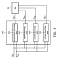
- Fig. 3 is a block diagram of the detection module in accordance with an embodiment of the invention.
- the detection module 103 includes the temperature-detecting unit 301, the speed-detecting unit 302, the current-detecting unit 303, and the voltage-detecting unit 304, in which each of the temperature-detecting unit 301, the speed-detecting unit 302, the current-detecting unit 303, and the voltage-detecting unit 304 includes an individual sensor (not shown in Fig. 3 ) on the fan 20.
- the temperature-detecting unit 301 receives the detection signal S D generated by the communication-processing module 101, the temperature-detecting unit 301 receives the temperature detection signal S ST generated by the sensor on the fan 20 according to the detection signal S D , in order to receive the temperature information.
- the temperature information includes the information of the ambient temperature and the temperature of the fan 20.
- the speed-detecting unit 302 receives the detection signal S D , the speed-detecting unit 302 receives the serial-pulse signal S SP generated by the sensor on the fan 20, in order to receive the speed information of the fan 20.
- the current-detecting unit 303 When the current-detecting unit 303 receives the detection signal S D , the current-detecting unit 303 receives the current-detecting signal S SI generated by the sensor on the fan 20, in order to receive the current information of the fan 20.
- the voltage-detecting unit 304 receives the detection signal S D , the voltage-detecting unit receives the voltage-detecting signal S SV generated by the sensor on the fan 20, in order to receive the voltage information.
- the temperature-detecting unit 301, the speed-detecting unit 302, the current-detecting unit 303, and the voltage-detecting unit 304 respectively transmit the temperature information, the speed information, the current information, and the voltage information to the communication-processing module 101.
- the temperature-detecting unit 301, the speed-detecting unit 302, the current-detecting unit 303, and the voltage-detecting unit 304 are physically separated from one another.
- the temperature-detecting unit 301, the speed-detecting unit 302, the current-detecting unit 303, and the voltage-detecting unit 304 are individually packaged.
- the detection module of the invention is not limited to detect temperature, speed, current, and voltage, and the detected items should be added according to the application field of the fan control device.
- the invention should not be taken in a limiting sense.
- a cooling fan is illustrated as an example in the following, and Figs. 1-3 are referenced for further explanation.
- the cooling fan is illustrated as an embodiment of the fan control device, but not limited thereto.
- the external system 10 is a human-computer interface system.
- the human-computer interface system When a user sets the temperature to be 30 degrees by the human-computer interface system, the human-computer interface system immediately transmits the fan-controlling instruction S I to the communication-processing module 101.
- the communication-processing module 101 requests, by the detection signal S D , the temperature-detecting unit 301 to receive the temperature detection signal S ST for detecting the ambient temperature and the temperature of the fan 20. After detection, the temperature-detecting unit 301 transmits the temperature information of the temperature detection signal S ST to the communication-processing module 101 by the state signal S S .
- the communication-processing module 101 when the communication-processing module 101 receives the temperature information, the communication-processing module 101 is aware of the ambient temperature being 35 degrees to determine that the ambient temperature is higher than that set by the user, such that the fan 20 needs to be started for cooling. Therefore, the control signal S C is transmitted to the start-controlling unit 202, and then the voltage signal S V is transmitted to start the fan 20. In addition, the speed-controlling unit 201 is also controlled by the control signal S C to generate the fan-control signal S CF for adjusting the speed of the fan 20 to a proper speed.
- the speed-controlling unit 201 and the start-controlling unit 202 accomplish the controlling, the speed-controlling unit 201 and the start-controlling unit 202 both notify, by the report signal S R , the communication-processing module 101 that the controlling has been successfully accomplished.
- the communication-processing module 101 when the communication-processing module 101 reports that the temperature of the fan 20 exceeds the safety range according to the temperature-detecting signal S ST received by the temperature-detecting unit 301, the communication-processing module 101 immediately transmits the control signal S C to lower the speed of the fan by the fan-control signal S CF generated by the speed-controlling unit 201, or to stop the fan 20 by the voltage signal S V generated by the start-controlling unit 202 and to restart the fan 20 according to the temperature-detecting signal S ST received by the temperature-detecting unit 301 when the temperature of the fan 20 is back to normal.
- the communication-processing module 101 could instantly adjust the operation of the fan 20 by the physical signal S P generated by the fan-controlling module 102 according to the ambient state and the fan state of the fan 20 of the sensor signal S T received by the detection module 103.
- the communication-processing module 101 could request the detection module 103 by the detection signal S D to stop collecting the state information (i.e., to stop receiving the sensor signal S T ) for the sake of reducing power consumption.
- the communication-processing module 101 could request the detection module 103 to collect the state information (i.e., to receive the sensor signal S T ) in a predetermined time interval and determine whether the adjustment of the fan 20 is required.
- the user could request the detection module 103 to collect the state information (i.e., to receive the sensor signal S T ) by the human-computer interface system (i.e., the external system 10) and display the instant state information of the detection signal S T on the human-computer interface system (i.e., the external system 10) for the user's interpretation.
- the human-computer interface system i.e., the external system
- the instant state information of the detection signal S T i.e., the external system
- the invention provides a fan control device with multiprocessor, in which each function is processed by a single processing module with a single function.
- the processing module with a single function is a circuit with a single function or a microprocessor with a single function. Since a circuit or a processor with a single function is much easier to be designed, the complexity of the processing module is greatly reduced, such that the efficiency of designing and cooling of the processing module is thus improved, and the overall cost is significantly reduced.
- the invention dismantles all the control functions into an individual processing module (could be a circuit of a processor), the communication-processing module is in charge of the communication among processing modules and the communication with the external system.
- Each of the control unit and the detection unit are physically separated from each other. That is, each of the control unit and the detection unit is only in charge of its own controlling or detecting task. If all the control and detection functions are dismantled into an independent unit, the design complexity is significantly lowered and the design cost is therefore reduced.
- the heat dissipating area is significantly enlarged, such that the cost of the heat dissipation is thus reduced and the overall cost of production is reduced as well. Accordingly, the production efficiency is improved.
Landscapes
- Engineering & Computer Science (AREA)
- Mechanical Engineering (AREA)
- General Engineering & Computer Science (AREA)
- Control Of Positive-Displacement Air Blowers (AREA)
- Cooling Or The Like Of Electrical Apparatus (AREA)
- Control Of Temperature (AREA)
Description
- This Application claims priority of China Patent Application No.
201410394680.X, filed on Aug. 12, 2014 - The disclosure relates generally to devices for controlling fans, and more particularly to a device with a multiprocessor for controlling fans.
- In an electronic system, such as a computer system, a cooling fan plays a key role in maintaining the proper functioning of the electronic system. The system would be permanently damaged if the excess heat could not be removed. Due to the complexity of modern electronic systems, cooling fans must do more than just cool air: extra features include controlling the speed of the fan, monitoring pulses on a tachometer to determine the instant speed of the fan, and detecting whether the fan becomes disabled or the speed is slower than expected.
- Most fans that have recently been released on the market are designed to have a single control unit. There are two methods by which fans with such a motor design are controlled: one is with analog control signals, and the other is with digital control signals. The method that uses analog control signals controls the speed of the motor by using different voltage signals. The main advantage of using analog control signals is that the control circuit of the system is simpler, but the stability of the speed and the resolution of speed control are much worse than in the method that uses digital control signals.
- The method that uses digital control signals controls the speed of the motor by communicating or adjusting the duty cycle of control signals. The main advantage of using digital control signals is its powerful subsidiary functions which are able to control or read more information. However, since the speed of communication has been rapidly improved with each passing day and there are more desired functions, the control unit of the motor can be overloaded, and so the motor-control function is limited. Therefore, a motor-control architecture with high efficiency is urgently needed to achieve a high quality and high efficacy in controlling a motor.
- To solve the problems described above, the invention provides a fan control device with multiprocessor.
- In an embodiment, a fan control device for controlling a fan comprises a communication-processing module, a fan-controlling module, and a detection module. The communication-processing module receives a fan-controlling instruction generated by an external system to generate a control signal, generates a detection signal according to a detection request of the external system, and provides state information for the external system. The fan-controlling module controls the speed of the fan according to the control signal, and transmits a control result to the communication-processing module. The detection module detects the ambient state and the fan state of the fan according to the detection signal, and generates state information from the ambient state and the fan state. The communication-processing module, the fan-controlling module, and the detection module are physically separated from one another.
- In an embodiment of the fan control device, the fan-controlling module further comprises a speed-controlling unit and a start-controlling unit. The speed-controlling unit controls the speed of the fan according to the control signal. The start-controlling unit controls the fan to start or stop according to the controlling signal. The speed-controlling unit and the start-controlling unit are physically separated from each other.
- In an embodiment of the fan control device, any one of the communication-processing module, the speed-controlling unit, and the start-controlling unit is individually packaged.
- In an embodiment of the fan control device, the detection module comprises a temperature-detecting unit, a speed-detecting unit, a current-detecting unit, and a voltage-detecting unit. The temperature-detecting unit detects temperature information according to the detection signal. The temperature information comprises ambient-temperature information and fan-temperature information. The speed-detecting unit detects speed information of the fan according to the detection signal. The current-detecting unit detects current information of the fan according to the detection signal. The voltage-detecting unit, detecting voltage information of the fan according to the detection signal. Each of the temperature-detecting unit, the speed-detecting unit, the current-detecting unit, and the voltage-detecting unit comprises a sensor, and the communication-processing module, the temperature-detecting unit, the speed-detecting unit, the current-detecting unit, and the voltage-detecting unit are physically separated from one another.
- In an embodiment of the fan control device, any one of the communication-processing module, the temperature-detecting unit, the speed-detecting unit, the current-detecting unit, and the voltage-detecting unit is individually packaged.
- In an embodiment of the fan control device, the external system is a human-computer interface system, the human-computer interface system generates the fan-controlling instruction according to an operation instruction of a user, and the speed of the fan is controlled by the control signal generated by the communication-processing module. The human-computer interface system further generates the detection request according to the operation instruction, requests the detection module to detect the ambient state and the fan state of the fan by the communication-processing module generating the detection signal, and then the human-computer interface system displays the state information transmitted by the communication-processing module.
- In an embodiment, a fan control device for controlling a fan comprises a communication-processing module, a speed-controlling unit, a start-controlling unit, a temperature-detecting unit, a speed-detecting unit, a current-detecting unit, and a voltage-detecting unit. The communication-processing module receives a fan-controlling instruction generated by an external system to generate a control signal, generates a detection signal according to a detection request of the external system, and provides state information for the external system. The speed-controlling unit controls the speed of the fan according to the control signal, and transmits a control result to the communication-processing module. The start-controlling unit controls the fan to start or stop according to the control signal, and transmits a start/stop result to the communication-processing module. The temperature-detecting unit detects temperature information according to the detection signal. The temperature information comprises ambient-temperature information and fan-temperature information. The speed-detecting unit detects speed information of the fan according to the detection signal. The current-detecting unit detects current information of the fan according to the detection signal. The voltage-detecting unit detects voltage information of the fan according to the detection signal. Each of the temperature-detecting unit, the speed-detecting unit, the current-detecting unit, and the voltage-detecting unit comprises a sensor, and the communication-processing module, the temperature-detecting unit, the speed-detecting unit, the current-detecting unit, and the voltage-detecting unit are physically separated from one another.
- In an embodiment of the fan control device, any one of the communication-processing module, the speed-controlling unit, the start-controlling unit, the temperature-detecting unit, the speed-detecting unit, the current-detecting unit, and the voltage-detecting unit is individually packaged.
- In an embodiment of the fan control device, the external system is a human-computer interface system, the human-computer interface system generates the fan-controlling instruction according to an operation instruction of a user, and the speed of the fan is controlled by the control signal generated by the communication-processing module. The human-computer interface system further generates the detection request according to the operation instruction, requests the detection module to detect the ambient state and the fan state of the fan by the communication-processing module generating the detection signal, and then the human-computer interface system displays the state information transmitted by the communication-processing module.
- A detailed description is given in the following embodiments with reference to the accompanying drawings.
- The invention can be more fully understood by reading the subsequent detailed description and examples with references made to the accompanying drawings, wherein:
-
Fig. 1 is a block diagram of the fan control device in accordance with an embodiment of the invention; -
Fig. 2 is a block diagram of the fan-controlling module in accordance with an embodiment of the invention; and -
Fig. 3 is a block diagram of the detection module in accordance with an embodiment of the invention. - The following description is of the best-contemplated mode of carrying out the invention. This description is made for the purpose of illustrating the general principles of the invention and should not be taken in a limiting sense. The scope of the invention is best determined by reference to the appended claims.
-
Fig. 1 is a block diagram of the fan control device in accordance with an embodiment of the invention. As shown inFig. 1 , thefan control device 100 includes the communication-processing module 101, the fan-controllingmodule 102, and thedetection module 103. The communication-processing module 101 receives the fan-controlling instruction SI transmitted from theexternal system 10 to generate the control signal SC. After receiving the control signal SC, the fan-controllingmodule 102 immediately notifies the communication-processing module 101 by the control result of the report signal SR that the adjustment and the control have been successfully accomplished. According to an embodiment of the invention, the fan-controllingmodule 102 controls the speed, and starts or stops thefan 20 by the physical signal SP, and it will be described in detail by an embodiment in the following. According to an embodiment of the invention, the physical signal SP is a PWM control signal or a control voltage. - The communication-
processing module 101 further generates the detection signal SD according to the detection request of the fan-controlling instruction SI transmitted from theexternal system 10. When thedetection module 103 receives the detection signal SD, the sensor (not shown inFig. 1 ) of thedetection module 103 immediately receives the sensor signal ST transmitted from thefan 20 to get the instant state information of thefan 20, and thedetection module 103 transmits the state information to the communication-processing module 101 by the state signal SS. theexternal system 10 can display the state information transmitted to the communication-processing module 101 according to the request of an user. According to an embodiment of the invention, the sensor signal ST is one or any combination of a voltage signal, a current signal, a signal with a series of pulses, and a temperature signal. - According to an embodiment of the invention, the state information includes the fan state of the
fan 20 and the ambient state at that time. The fan state of thefan 20 includes the information of the temperature, the speed, the voltage, the current, and so on of thefan 20. The ambient state includes the ambient temperature at that time. According to an embodiment of the invention, the fan-controllingmodule 102 and thedetection module 103 are physically separated from each other, and there is no data transmission therebetween. According to another embodiment of the invention, the communication-processing module 101, the fan-controllingmodule 102, and thedetection module 103 are individually packaged. -
Fig. 2 is a block diagram of the fan-controlling module in accordance with an embodiment of the invention. As shown inFig. 2 , the fan-controllingmodule 102 includes the speed-controllingunit 201 and the start-controllingunit 202. The speed-controllingunit 201 generates the fan-control signal SCF according to the control signal SC, in order to control the speed of thefan 20. When the speed-controllingunit 201 controls the speed of thefan 20, the speed-controllingunit 201 immediately notifies the communication-processing module 101 by the report signal SR that the action of controlling has been successfully accomplished. According to an embodiment of the invention, the fan-control signal SCF is a PWM signal or a voltage signal. - The start-controlling
unit 202 generates the voltage signal SV according to the control signal SC, in order to control thefan 20 to start or stop. When the start-controllingunit 202 starts or stops thefan 20, the start-controllingunit 202 immediately notifies the communication-processing module 101 by the report signal SR that the action of starting or stopping has been successfully accomplished. According to an embodiment of the invention, the speed-controllingunit 201 and the start-controllingunit 202 are physically separated from each other, and both are operated independently without communication therebetween. According to another embodiment of the invention, the speed-controllingunit 201 and the start-controllingunit 202 are packaged individually. According to an embodiment of the invention, the voltage SV is 0V or 5V when the operation voltage is 5V. - The functions of the speed-controlling and the start-controlling herein are described for illustration. The fan-controlling module includes the functions of controlling a fan that are invented afterward and not intend to be limited thereto.
-
Fig. 3 is a block diagram of the detection module in accordance with an embodiment of the invention. Thedetection module 103 includes the temperature-detectingunit 301, the speed-detectingunit 302, the current-detectingunit 303, and the voltage-detectingunit 304, in which each of the temperature-detectingunit 301, the speed-detectingunit 302, the current-detectingunit 303, and the voltage-detectingunit 304 includes an individual sensor (not shown inFig. 3 ) on thefan 20. - When the temperature-detecting
unit 301 receives the detection signal SD generated by the communication-processing module 101, the temperature-detectingunit 301 receives the temperature detection signal SST generated by the sensor on thefan 20 according to the detection signal SD, in order to receive the temperature information. According to an embodiment of the invention, the temperature information includes the information of the ambient temperature and the temperature of thefan 20. When the speed-detectingunit 302 receives the detection signal SD, the speed-detectingunit 302 receives the serial-pulse signal SSP generated by the sensor on thefan 20, in order to receive the speed information of thefan 20. When the current-detectingunit 303 receives the detection signal SD, the current-detectingunit 303 receives the current-detecting signal SSI generated by the sensor on thefan 20, in order to receive the current information of thefan 20. When the voltage-detectingunit 304 receives the detection signal SD, the voltage-detecting unit receives the voltage-detecting signal SSV generated by the sensor on thefan 20, in order to receive the voltage information. - By the state signal SS, the temperature-detecting
unit 301, the speed-detectingunit 302, the current-detectingunit 303, and the voltage-detectingunit 304 respectively transmit the temperature information, the speed information, the current information, and the voltage information to the communication-processing module 101. According to an embodiment of the invention, the temperature-detectingunit 301, the speed-detectingunit 302, the current-detectingunit 303, and the voltage-detectingunit 304 are physically separated from one another. According to another embodiment of the invention, the temperature-detectingunit 301, the speed-detectingunit 302, the current-detectingunit 303, and the voltage-detectingunit 304 are individually packaged. - According to an embodiment of the invention, the detection module of the invention is not limited to detect temperature, speed, current, and voltage, and the detected items should be added according to the application field of the fan control device. The invention should not be taken in a limiting sense.
- For the sake of clearly explaining the usage of the fan control device of the invention, a cooling fan is illustrated as an example in the following, and
Figs. 1-3 are referenced for further explanation. In addition, the cooling fan is illustrated as an embodiment of the fan control device, but not limited thereto. - According to an embodiment, the
external system 10 is a human-computer interface system. When a user sets the temperature to be 30 degrees by the human-computer interface system, the human-computer interface system immediately transmits the fan-controlling instruction SI to the communication-processing module 101. When receiving the fan-controlling instruction SI, the communication-processing module 101 requests, by the detection signal SD, the temperature-detectingunit 301 to receive the temperature detection signal SST for detecting the ambient temperature and the temperature of thefan 20. After detection, the temperature-detectingunit 301 transmits the temperature information of the temperature detection signal SST to the communication-processing module 101 by the state signal SS. - According to an embodiment of the invention, when the communication-
processing module 101 receives the temperature information, the communication-processing module 101 is aware of the ambient temperature being 35 degrees to determine that the ambient temperature is higher than that set by the user, such that thefan 20 needs to be started for cooling. Therefore, the control signal SC is transmitted to the start-controllingunit 202, and then the voltage signal SV is transmitted to start thefan 20. In addition, the speed-controllingunit 201 is also controlled by the control signal SC to generate the fan-control signal SCF for adjusting the speed of thefan 20 to a proper speed. When the speed-controllingunit 201 and the start-controllingunit 202 accomplish the controlling, the speed-controllingunit 201 and the start-controllingunit 202 both notify, by the report signal SR, the communication-processing module 101 that the controlling has been successfully accomplished. - According to an embodiment of the invention, when the communication-
processing module 101 reports that the temperature of thefan 20 exceeds the safety range according to the temperature-detecting signal SST received by the temperature-detectingunit 301, the communication-processing module 101 immediately transmits the control signal SC to lower the speed of the fan by the fan-control signal SCF generated by the speed-controllingunit 201, or to stop thefan 20 by the voltage signal SV generated by the start-controllingunit 202 and to restart thefan 20 according to the temperature-detecting signal SST received by the temperature-detectingunit 301 when the temperature of thefan 20 is back to normal. - According to an embodiment of the invention, the communication-
processing module 101 could instantly adjust the operation of thefan 20 by the physical signal SP generated by the fan-controllingmodule 102 according to the ambient state and the fan state of thefan 20 of the sensor signal ST received by thedetection module 103. According to another embodiment of the invention, the communication-processing module 101 could request thedetection module 103 by the detection signal SD to stop collecting the state information (i.e., to stop receiving the sensor signal ST) for the sake of reducing power consumption. According to yet another embodiment of the invention, the communication-processing module 101 could request thedetection module 103 to collect the state information (i.e., to receive the sensor signal ST) in a predetermined time interval and determine whether the adjustment of thefan 20 is required. - According to an embodiment of the invention, the user could request the
detection module 103 to collect the state information (i.e., to receive the sensor signal ST) by the human-computer interface system (i.e., the external system 10) and display the instant state information of the detection signal ST on the human-computer interface system (i.e., the external system 10) for the user's interpretation. - The invention provides a fan control device with multiprocessor, in which each function is processed by a single processing module with a single function. According to an embodiment of the invention, the processing module with a single function is a circuit with a single function or a microprocessor with a single function. Since a circuit or a processor with a single function is much easier to be designed, the complexity of the processing module is greatly reduced, such that the efficiency of designing and cooling of the processing module is thus improved, and the overall cost is significantly reduced.
- Regarding the conventional method of integrating all the functions of control, detection, and communication into a single processing module on the market, since it is very complicated between various functions, a lot of human resources and time are spent clarifying whether the unexpected effect could have occurred by the interactions between various functions. Otherwise, the processing module would be unexpectedly damaged. In addition, since all the functions are integrated into a processing module, the heating power of the processing module should be raised accordingly. When there are more functions in a processing module, even an additional fan is required for cooling.
- The invention dismantles all the control functions into an individual processing module (could be a circuit of a processor), the communication-processing module is in charge of the communication among processing modules and the communication with the external system. Each of the control unit and the detection unit are physically separated from each other. That is, each of the control unit and the detection unit is only in charge of its own controlling or detecting task. If all the control and detection functions are dismantled into an independent unit, the design complexity is significantly lowered and the design cost is therefore reduced. In addition, when a single processing module is dismantled into several processing modules, the heat dissipating area is significantly enlarged, such that the cost of the heat dissipation is thus reduced and the overall cost of production is reduced as well. Accordingly, the production efficiency is improved.
- While the invention has been described by way of example and in terms of preferred embodiment, it is to be understood that the invention is not limited thereto. Those who are skilled in this technology can still make various alterations and modifications without departing from the scope and spirit of this invention. Therefore, the scope of the present invention shall be defined and protected by the following claims and their equivalents.
Claims (6)
- A fan control device for controlling a fan comprising:a communication-processing module, receiving a fan-controlling instruction generated by an external system to generate a control signal, generating a detection signal according to a detection request of the external system, and providing state information for the external system;a fan-controlling module, controlling a speed of the fan according to the control signal, and transmitting a control result to the communication-processing module; anda detection module, detecting an ambient state and a fan state of the fan according to the detection signal, and generating the state information according to the ambient information and the fan state, wherein the communication-processing module, the fan-controlling module, and the detection module are physically separated from one another.
- The fan control device of claim 1, wherein the fan-controlling module further comprises:a speed-controlling unit, controlling the speed of the fan according to the control signal; anda start-controlling unit, controlling the fan to start or stop according to the control signal, wherein the speed-controlling unit and the start-controlling unit are physically separated from each other.
- The fan control device of claim 2, wherein any one of the communication-processing module, the speed-controlling unit, and the start-controlling unit is individually packaged.
- The fan control device of claim 1, wherein the detection module comprises:a temperature-detecting unit, detecting temperature information according to the detection signal, wherein the temperature information comprises ambient-temperature information and fan-temperature information;a speed-detecting unit, detecting speed information of the fan according to the detection signal;a current-detecting unit, detecting current information of the fan according to the detection signal; anda voltage-detecting unit, detecting voltage information of the fan according to the detection signal, wherein each of the temperature-detecting unit, the speed-detecting unit, the current-detecting unit, and the voltage-detecting unit comprises a sensor, and the communication-processing module, the temperature-detecting unit, the speed-detecting unit, the current-detecting unit, and the voltage-detecting unit are physically separated from one another.
- The fan control device of claim 4, wherein any one of the communication-processing cr module, the temperature-detecting unit, the speed-detecting unit, the current-detecting unit, and the voltage-detecting unit is individually packaged.
- The fan control device of claim 4, wherein the external system is a human-computer interface system, the human-computer interface system generates the fan-controlling instruction according to an operation instruction of a user, and controls the speed of the fan by the control signal generated by the communication-processing module, wherein the human-computer interface system further generates the detection request according to the operation instruction, requests the detection module to detect the ambient state and the fan state of the fan by the communication-processing module generating the detection signal, and then the human-computer interface system displays the state information transmitted by the communication-processing module.
Applications Claiming Priority (1)
| Application Number | Priority Date | Filing Date | Title |
|---|---|---|---|
| CN201410394680.XA CN105332936B (en) | 2014-08-12 | 2014-08-12 | Fan control device |
Publications (2)
| Publication Number | Publication Date |
|---|---|
| EP2985467A1 true EP2985467A1 (en) | 2016-02-17 |
| EP2985467B1 EP2985467B1 (en) | 2019-07-03 |
Family
ID=53836468
Family Applications (1)
| Application Number | Title | Priority Date | Filing Date |
|---|---|---|---|
| EP15180718.7A Active EP2985467B1 (en) | 2014-08-12 | 2015-08-12 | Fan control device with multiprocessor |
Country Status (3)
| Country | Link |
|---|---|
| US (2) | US20160047390A1 (en) |
| EP (1) | EP2985467B1 (en) |
| CN (1) | CN105332936B (en) |
Families Citing this family (3)
| Publication number | Priority date | Publication date | Assignee | Title |
|---|---|---|---|---|
| CN110778514B (en) * | 2018-07-25 | 2022-02-22 | 矽创电子股份有限公司 | Fan control system |
| US11661950B2 (en) * | 2020-11-20 | 2023-05-30 | Lg Energy Solution, Ltd. | Diagnostic system for a vehicle |
| TWI798998B (en) * | 2021-12-15 | 2023-04-11 | 登騰電子股份有限公司 | Fan system and monitoring method for fan system |
Citations (4)
| Publication number | Priority date | Publication date | Assignee | Title |
|---|---|---|---|---|
| US20030234630A1 (en) * | 1999-12-23 | 2003-12-25 | John Blake | Fan speed control system |
| US20070248467A1 (en) * | 2006-04-21 | 2007-10-25 | Shahi Prakash B | Fluid flow control for fluid handling systems |
| US20100291858A1 (en) * | 2008-02-04 | 2010-11-18 | Delta T Corporation | Automatic control system for ceiling fan based on temperature differentials |
| US20140163918A1 (en) * | 2012-12-07 | 2014-06-12 | Hon Hai Precision Industry Co., Ltd. | Fan module test system |
Family Cites Families (13)
| Publication number | Priority date | Publication date | Assignee | Title |
|---|---|---|---|---|
| US7103761B2 (en) | 2001-08-07 | 2006-09-05 | Hewlett-Packard Development Company, Lp. | Server system with multiple management user interfaces |
| US6725132B2 (en) * | 2002-06-20 | 2004-04-20 | Minebea Co., Ltd. | Intelligent cooling fan |
| US6956342B1 (en) * | 2004-04-30 | 2005-10-18 | Datech Technology Co., Ltd. | Driving circuit for a DC brushless fan motor |
| TWI240156B (en) * | 2004-05-18 | 2005-09-21 | Delta Electronics Inc | Temperature and humidity sensing speed control system for fan |
| TWI249097B (en) * | 2004-08-17 | 2006-02-11 | Compal Electronics Inc | Method of auto-regulating rotational speed of a fan |
| US20070297893A1 (en) * | 2006-06-27 | 2007-12-27 | Winbond Electronics Corporation | Fan speed change control |
| CN201622455U (en) * | 2009-03-27 | 2010-11-03 | 深圳市中兴新地通信器材有限公司 | Novel heat exchanger AC control system |
| CN101545497B (en) * | 2009-04-30 | 2011-05-04 | 上海大学 | Automobile engine cooling fan control system based on four-phase double-wire winding brushless DC motor |
| CN101581933A (en) * | 2009-05-12 | 2009-11-18 | 深圳市中兴新地通信器材有限公司 | Multi-heat dissipation device intelligent linkage machine room energy-saving control system |
| TWM390647U (en) | 2010-04-29 | 2010-10-11 | Delta Electronics Inc | Power supply circuit and fan driving circuit thereof with auto-regulated rotation speed |
| CN201916228U (en) * | 2010-12-28 | 2011-08-03 | 广州精益汽车空调有限公司 | Brushless fan controller without position sensor |
| JP5724933B2 (en) | 2012-04-06 | 2015-05-27 | ダイキン工業株式会社 | Control device and heat pump device |
| CN103644136B (en) * | 2013-12-24 | 2016-03-02 | 华为技术有限公司 | A kind of fan control system, system administration manager and fan |
-
2014
- 2014-08-12 CN CN201410394680.XA patent/CN105332936B/en active Active
-
2015
- 2015-08-12 EP EP15180718.7A patent/EP2985467B1/en active Active
- 2015-08-12 US US14/824,429 patent/US20160047390A1/en not_active Abandoned
-
2018
- 2018-04-19 US US15/957,371 patent/US10954950B2/en active Active
Patent Citations (4)
| Publication number | Priority date | Publication date | Assignee | Title |
|---|---|---|---|---|
| US20030234630A1 (en) * | 1999-12-23 | 2003-12-25 | John Blake | Fan speed control system |
| US20070248467A1 (en) * | 2006-04-21 | 2007-10-25 | Shahi Prakash B | Fluid flow control for fluid handling systems |
| US20100291858A1 (en) * | 2008-02-04 | 2010-11-18 | Delta T Corporation | Automatic control system for ceiling fan based on temperature differentials |
| US20140163918A1 (en) * | 2012-12-07 | 2014-06-12 | Hon Hai Precision Industry Co., Ltd. | Fan module test system |
Also Published As
| Publication number | Publication date |
|---|---|
| US20180238335A1 (en) | 2018-08-23 |
| US10954950B2 (en) | 2021-03-23 |
| CN105332936B (en) | 2017-09-19 |
| US20160047390A1 (en) | 2016-02-18 |
| EP2985467B1 (en) | 2019-07-03 |
| CN105332936A (en) | 2016-02-17 |
Similar Documents
| Publication | Publication Date | Title |
|---|---|---|
| CN106062653B (en) | Method and electronic device for controlling electric current | |
| US20140018958A1 (en) | Safety system and control device | |
| US10954950B2 (en) | Fan control device with multiprocessor | |
| JP5441875B2 (en) | Computer system | |
| US20130229765A1 (en) | Temperature control device for hard disk drive of server system | |
| US20180164795A1 (en) | Fan monitoring system | |
| KR20150097330A (en) | Method and Apparatus for Controlling Battery Charging | |
| US10157115B2 (en) | Detection system and method for baseboard management controller | |
| US11436170B2 (en) | Digital bus activity monitor | |
| US9817461B2 (en) | Abnormality display device including a switch to control a display element to indicate abnormal or normal operations for plural systems | |
| EP3627282A1 (en) | Thermal management via operating system | |
| US20130289793A1 (en) | Fan control system | |
| TW201118596A (en) | Server management system | |
| US10284134B2 (en) | Method for controlling a fan module of a server rack and controller unit for implementing the same | |
| US20120118555A1 (en) | Noise reduction apparatus, method, and container data center including the same | |
| US20140125251A1 (en) | Flat panel electronic device and current control system thereof | |
| CN104074784A (en) | Fan control system and method | |
| TWI550193B (en) | Fan-controlling devices | |
| US9184604B2 (en) | Charging methods of detachable electronic devices | |
| CN109586552B (en) | Power unit, STO method, user interface control device and STO signal processing method | |
| US20150032284A1 (en) | Detection module, device and system for detecting fan's connection and disconnection states | |
| CN105468495B (en) | Complicated formula can procedure logical control system device | |
| US10362715B2 (en) | Automatically cooling computer system components for safe servicing | |
| CN117148937A (en) | Board card heat dissipation methods and systems, storage media and electronic equipment | |
| US9836425B2 (en) | Computer apparatus, datapath switching apparatus and associated method for switching datapaths for transmitting sensing data according to operating system utilized by computer apparatus |
Legal Events
| Date | Code | Title | Description |
|---|---|---|---|
| PUAI | Public reference made under article 153(3) epc to a published international application that has entered the european phase |
Free format text: ORIGINAL CODE: 0009012 |
|
| AK | Designated contracting states |
Kind code of ref document: A1 Designated state(s): AL AT BE BG CH CY CZ DE DK EE ES FI FR GB GR HR HU IE IS IT LI LT LU LV MC MK MT NL NO PL PT RO RS SE SI SK SM TR |
|
| AX | Request for extension of the european patent |
Extension state: BA ME |
|
| 17P | Request for examination filed |
Effective date: 20160816 |
|
| RBV | Designated contracting states (corrected) |
Designated state(s): AL AT BE BG CH CY CZ DE DK EE ES FI FR GB GR HR HU IE IS IT LI LT LU LV MC MK MT NL NO PL PT RO RS SE SI SK SM TR |
|
| STAA | Information on the status of an ep patent application or granted ep patent |
Free format text: STATUS: EXAMINATION IS IN PROGRESS |
|
| 17Q | First examination report despatched |
Effective date: 20180220 |
|
| GRAP | Despatch of communication of intention to grant a patent |
Free format text: ORIGINAL CODE: EPIDOSNIGR1 |
|
| STAA | Information on the status of an ep patent application or granted ep patent |
Free format text: STATUS: GRANT OF PATENT IS INTENDED |
|
| INTG | Intention to grant announced |
Effective date: 20190212 |
|
| GRAS | Grant fee paid |
Free format text: ORIGINAL CODE: EPIDOSNIGR3 |
|
| GRAA | (expected) grant |
Free format text: ORIGINAL CODE: 0009210 |
|
| STAA | Information on the status of an ep patent application or granted ep patent |
Free format text: STATUS: THE PATENT HAS BEEN GRANTED |
|
| AK | Designated contracting states |
Kind code of ref document: B1 Designated state(s): AL AT BE BG CH CY CZ DE DK EE ES FI FR GB GR HR HU IE IS IT LI LT LU LV MC MK MT NL NO PL PT RO RS SE SI SK SM TR |
|
| REG | Reference to a national code |
Ref country code: GB Ref legal event code: FG4D |
|
| REG | Reference to a national code |
Ref country code: CH Ref legal event code: EP Ref country code: AT Ref legal event code: REF Ref document number: 1151347 Country of ref document: AT Kind code of ref document: T Effective date: 20190715 |
|
| REG | Reference to a national code |
Ref country code: IE Ref legal event code: FG4D |
|
| REG | Reference to a national code |
Ref country code: DE Ref legal event code: R096 Ref document number: 602015033016 Country of ref document: DE |
|
| REG | Reference to a national code |
Ref country code: NL Ref legal event code: MP Effective date: 20190703 |
|
| REG | Reference to a national code |
Ref country code: LT Ref legal event code: MG4D |
|
| REG | Reference to a national code |
Ref country code: AT Ref legal event code: MK05 Ref document number: 1151347 Country of ref document: AT Kind code of ref document: T Effective date: 20190703 |
|
| PG25 | Lapsed in a contracting state [announced via postgrant information from national office to epo] |
Ref country code: NO Free format text: LAPSE BECAUSE OF FAILURE TO SUBMIT A TRANSLATION OF THE DESCRIPTION OR TO PAY THE FEE WITHIN THE PRESCRIBED TIME-LIMIT Effective date: 20191003 Ref country code: FI Free format text: LAPSE BECAUSE OF FAILURE TO SUBMIT A TRANSLATION OF THE DESCRIPTION OR TO PAY THE FEE WITHIN THE PRESCRIBED TIME-LIMIT Effective date: 20190703 Ref country code: SE Free format text: LAPSE BECAUSE OF FAILURE TO SUBMIT A TRANSLATION OF THE DESCRIPTION OR TO PAY THE FEE WITHIN THE PRESCRIBED TIME-LIMIT Effective date: 20190703 Ref country code: HR Free format text: LAPSE BECAUSE OF FAILURE TO SUBMIT A TRANSLATION OF THE DESCRIPTION OR TO PAY THE FEE WITHIN THE PRESCRIBED TIME-LIMIT Effective date: 20190703 Ref country code: LT Free format text: LAPSE BECAUSE OF FAILURE TO SUBMIT A TRANSLATION OF THE DESCRIPTION OR TO PAY THE FEE WITHIN THE PRESCRIBED TIME-LIMIT Effective date: 20190703 Ref country code: AT Free format text: LAPSE BECAUSE OF FAILURE TO SUBMIT A TRANSLATION OF THE DESCRIPTION OR TO PAY THE FEE WITHIN THE PRESCRIBED TIME-LIMIT Effective date: 20190703 Ref country code: CZ Free format text: LAPSE BECAUSE OF FAILURE TO SUBMIT A TRANSLATION OF THE DESCRIPTION OR TO PAY THE FEE WITHIN THE PRESCRIBED TIME-LIMIT Effective date: 20190703 Ref country code: PT Free format text: LAPSE BECAUSE OF FAILURE TO SUBMIT A TRANSLATION OF THE DESCRIPTION OR TO PAY THE FEE WITHIN THE PRESCRIBED TIME-LIMIT Effective date: 20191104 Ref country code: NL Free format text: LAPSE BECAUSE OF FAILURE TO SUBMIT A TRANSLATION OF THE DESCRIPTION OR TO PAY THE FEE WITHIN THE PRESCRIBED TIME-LIMIT Effective date: 20190703 Ref country code: BG Free format text: LAPSE BECAUSE OF FAILURE TO SUBMIT A TRANSLATION OF THE DESCRIPTION OR TO PAY THE FEE WITHIN THE PRESCRIBED TIME-LIMIT Effective date: 20191003 |
|
| PG25 | Lapsed in a contracting state [announced via postgrant information from national office to epo] |
Ref country code: AL Free format text: LAPSE BECAUSE OF FAILURE TO SUBMIT A TRANSLATION OF THE DESCRIPTION OR TO PAY THE FEE WITHIN THE PRESCRIBED TIME-LIMIT Effective date: 20190703 Ref country code: ES Free format text: LAPSE BECAUSE OF FAILURE TO SUBMIT A TRANSLATION OF THE DESCRIPTION OR TO PAY THE FEE WITHIN THE PRESCRIBED TIME-LIMIT Effective date: 20190703 Ref country code: LV Free format text: LAPSE BECAUSE OF FAILURE TO SUBMIT A TRANSLATION OF THE DESCRIPTION OR TO PAY THE FEE WITHIN THE PRESCRIBED TIME-LIMIT Effective date: 20190703 Ref country code: RS Free format text: LAPSE BECAUSE OF FAILURE TO SUBMIT A TRANSLATION OF THE DESCRIPTION OR TO PAY THE FEE WITHIN THE PRESCRIBED TIME-LIMIT Effective date: 20190703 Ref country code: GR Free format text: LAPSE BECAUSE OF FAILURE TO SUBMIT A TRANSLATION OF THE DESCRIPTION OR TO PAY THE FEE WITHIN THE PRESCRIBED TIME-LIMIT Effective date: 20191004 Ref country code: IS Free format text: LAPSE BECAUSE OF FAILURE TO SUBMIT A TRANSLATION OF THE DESCRIPTION OR TO PAY THE FEE WITHIN THE PRESCRIBED TIME-LIMIT Effective date: 20191103 |
|
| PG25 | Lapsed in a contracting state [announced via postgrant information from national office to epo] |
Ref country code: TR Free format text: LAPSE BECAUSE OF FAILURE TO SUBMIT A TRANSLATION OF THE DESCRIPTION OR TO PAY THE FEE WITHIN THE PRESCRIBED TIME-LIMIT Effective date: 20190703 |
|
| PG25 | Lapsed in a contracting state [announced via postgrant information from national office to epo] |
Ref country code: RO Free format text: LAPSE BECAUSE OF FAILURE TO SUBMIT A TRANSLATION OF THE DESCRIPTION OR TO PAY THE FEE WITHIN THE PRESCRIBED TIME-LIMIT Effective date: 20190703 Ref country code: IT Free format text: LAPSE BECAUSE OF FAILURE TO SUBMIT A TRANSLATION OF THE DESCRIPTION OR TO PAY THE FEE WITHIN THE PRESCRIBED TIME-LIMIT Effective date: 20190703 Ref country code: PL Free format text: LAPSE BECAUSE OF FAILURE TO SUBMIT A TRANSLATION OF THE DESCRIPTION OR TO PAY THE FEE WITHIN THE PRESCRIBED TIME-LIMIT Effective date: 20190703 Ref country code: EE Free format text: LAPSE BECAUSE OF FAILURE TO SUBMIT A TRANSLATION OF THE DESCRIPTION OR TO PAY THE FEE WITHIN THE PRESCRIBED TIME-LIMIT Effective date: 20190703 Ref country code: DK Free format text: LAPSE BECAUSE OF FAILURE TO SUBMIT A TRANSLATION OF THE DESCRIPTION OR TO PAY THE FEE WITHIN THE PRESCRIBED TIME-LIMIT Effective date: 20190703 |
|
| PG25 | Lapsed in a contracting state [announced via postgrant information from national office to epo] |
Ref country code: LI Free format text: LAPSE BECAUSE OF NON-PAYMENT OF DUE FEES Effective date: 20190831 Ref country code: IS Free format text: LAPSE BECAUSE OF FAILURE TO SUBMIT A TRANSLATION OF THE DESCRIPTION OR TO PAY THE FEE WITHIN THE PRESCRIBED TIME-LIMIT Effective date: 20200224 Ref country code: SM Free format text: LAPSE BECAUSE OF FAILURE TO SUBMIT A TRANSLATION OF THE DESCRIPTION OR TO PAY THE FEE WITHIN THE PRESCRIBED TIME-LIMIT Effective date: 20190703 Ref country code: CH Free format text: LAPSE BECAUSE OF NON-PAYMENT OF DUE FEES Effective date: 20190831 Ref country code: LU Free format text: LAPSE BECAUSE OF NON-PAYMENT OF DUE FEES Effective date: 20190812 Ref country code: SK Free format text: LAPSE BECAUSE OF FAILURE TO SUBMIT A TRANSLATION OF THE DESCRIPTION OR TO PAY THE FEE WITHIN THE PRESCRIBED TIME-LIMIT Effective date: 20190703 Ref country code: MC Free format text: LAPSE BECAUSE OF FAILURE TO SUBMIT A TRANSLATION OF THE DESCRIPTION OR TO PAY THE FEE WITHIN THE PRESCRIBED TIME-LIMIT Effective date: 20190703 |
|
| REG | Reference to a national code |
Ref country code: BE Ref legal event code: MM Effective date: 20190831 |
|
| REG | Reference to a national code |
Ref country code: DE Ref legal event code: R097 Ref document number: 602015033016 Country of ref document: DE |
|
| PLBE | No opposition filed within time limit |
Free format text: ORIGINAL CODE: 0009261 |
|
| STAA | Information on the status of an ep patent application or granted ep patent |
Free format text: STATUS: NO OPPOSITION FILED WITHIN TIME LIMIT |
|
| PG2D | Information on lapse in contracting state deleted |
Ref country code: IS |
|
| PG25 | Lapsed in a contracting state [announced via postgrant information from national office to epo] |
Ref country code: FR Free format text: LAPSE BECAUSE OF NON-PAYMENT OF DUE FEES Effective date: 20190903 Ref country code: IE Free format text: LAPSE BECAUSE OF NON-PAYMENT OF DUE FEES Effective date: 20190812 |
|
| 26N | No opposition filed |
Effective date: 20200603 |
|
| PG25 | Lapsed in a contracting state [announced via postgrant information from national office to epo] |
Ref country code: BE Free format text: LAPSE BECAUSE OF NON-PAYMENT OF DUE FEES Effective date: 20190831 Ref country code: SI Free format text: LAPSE BECAUSE OF FAILURE TO SUBMIT A TRANSLATION OF THE DESCRIPTION OR TO PAY THE FEE WITHIN THE PRESCRIBED TIME-LIMIT Effective date: 20190703 |
|
| GBPC | Gb: european patent ceased through non-payment of renewal fee |
Effective date: 20191003 |
|
| PG25 | Lapsed in a contracting state [announced via postgrant information from national office to epo] |
Ref country code: GB Free format text: LAPSE BECAUSE OF NON-PAYMENT OF DUE FEES Effective date: 20191003 |
|
| PG25 | Lapsed in a contracting state [announced via postgrant information from national office to epo] |
Ref country code: CY Free format text: LAPSE BECAUSE OF FAILURE TO SUBMIT A TRANSLATION OF THE DESCRIPTION OR TO PAY THE FEE WITHIN THE PRESCRIBED TIME-LIMIT Effective date: 20190703 |
|
| PG25 | Lapsed in a contracting state [announced via postgrant information from national office to epo] |
Ref country code: MT Free format text: LAPSE BECAUSE OF FAILURE TO SUBMIT A TRANSLATION OF THE DESCRIPTION OR TO PAY THE FEE WITHIN THE PRESCRIBED TIME-LIMIT Effective date: 20190703 Ref country code: HU Free format text: LAPSE BECAUSE OF FAILURE TO SUBMIT A TRANSLATION OF THE DESCRIPTION OR TO PAY THE FEE WITHIN THE PRESCRIBED TIME-LIMIT; INVALID AB INITIO Effective date: 20150812 |
|
| PG25 | Lapsed in a contracting state [announced via postgrant information from national office to epo] |
Ref country code: MK Free format text: LAPSE BECAUSE OF FAILURE TO SUBMIT A TRANSLATION OF THE DESCRIPTION OR TO PAY THE FEE WITHIN THE PRESCRIBED TIME-LIMIT Effective date: 20190703 |
|
| PGFP | Annual fee paid to national office [announced via postgrant information from national office to epo] |
Ref country code: DE Payment date: 20250827 Year of fee payment: 11 |