EP2985233A1 - Food storage appliance with moisture sensor - Google Patents
Food storage appliance with moisture sensor Download PDFInfo
- Publication number
- EP2985233A1 EP2985233A1 EP15002404.0A EP15002404A EP2985233A1 EP 2985233 A1 EP2985233 A1 EP 2985233A1 EP 15002404 A EP15002404 A EP 15002404A EP 2985233 A1 EP2985233 A1 EP 2985233A1
- Authority
- EP
- European Patent Office
- Prior art keywords
- trace
- appendages
- food storage
- signal
- food
- Prior art date
- Legal status (The legal status is an assumption and is not a legal conclusion. Google has not performed a legal analysis and makes no representation as to the accuracy of the status listed.)
- Granted
Links
- 239000007788 liquid Substances 0.000 claims abstract description 31
- 238000007789 sealing Methods 0.000 claims abstract description 23
- 238000009920 food preservation Methods 0.000 claims description 22
- 239000004020 conductor Substances 0.000 claims description 11
- 239000000758 substrate Substances 0.000 claims description 11
- 238000000034 method Methods 0.000 claims description 7
- RYGMFSIKBFXOCR-UHFFFAOYSA-N Copper Chemical compound [Cu] RYGMFSIKBFXOCR-UHFFFAOYSA-N 0.000 claims description 3
- BQCADISMDOOEFD-UHFFFAOYSA-N Silver Chemical compound [Ag] BQCADISMDOOEFD-UHFFFAOYSA-N 0.000 claims description 3
- 229910052782 aluminium Inorganic materials 0.000 claims description 3
- XAGFODPZIPBFFR-UHFFFAOYSA-N aluminium Chemical compound [Al] XAGFODPZIPBFFR-UHFFFAOYSA-N 0.000 claims description 3
- 229910052802 copper Inorganic materials 0.000 claims description 3
- 239000010949 copper Substances 0.000 claims description 3
- PCHJSUWPFVWCPO-UHFFFAOYSA-N gold Chemical compound [Au] PCHJSUWPFVWCPO-UHFFFAOYSA-N 0.000 claims description 3
- 229910052737 gold Inorganic materials 0.000 claims description 3
- 239000010931 gold Substances 0.000 claims description 3
- 229910052751 metal Inorganic materials 0.000 claims description 3
- 239000002184 metal Substances 0.000 claims description 3
- 229910052709 silver Inorganic materials 0.000 claims description 3
- 239000004332 silver Substances 0.000 claims description 3
- 230000001419 dependent effect Effects 0.000 claims 1
- 229920006280 packaging film Polymers 0.000 description 7
- 239000012785 packaging film Substances 0.000 description 7
- 238000004806 packaging method and process Methods 0.000 description 5
- 230000004888 barrier function Effects 0.000 description 3
- 230000008901 benefit Effects 0.000 description 2
- 230000005684 electric field Effects 0.000 description 2
- 230000006870 function Effects 0.000 description 2
- 230000007246 mechanism Effects 0.000 description 2
- 238000012986 modification Methods 0.000 description 2
- 230000004048 modification Effects 0.000 description 2
- 230000001934 delay Effects 0.000 description 1
- 238000010586 diagram Methods 0.000 description 1
- 239000000463 material Substances 0.000 description 1
- 238000009461 vacuum packaging Methods 0.000 description 1
Images

Classifications
-
- G—PHYSICS
- G01—MEASURING; TESTING
- G01N—INVESTIGATING OR ANALYSING MATERIALS BY DETERMINING THEIR CHEMICAL OR PHYSICAL PROPERTIES
- G01N33/00—Investigating or analysing materials by specific methods not covered by groups G01N1/00 - G01N31/00
- G01N33/02—Food
-
- A—HUMAN NECESSITIES
- A23—FOODS OR FOODSTUFFS; TREATMENT THEREOF, NOT COVERED BY OTHER CLASSES
- A23L—FOODS, FOODSTUFFS, OR NON-ALCOHOLIC BEVERAGES, NOT COVERED BY SUBCLASSES A21D OR A23B-A23J; THEIR PREPARATION OR TREATMENT, e.g. COOKING, MODIFICATION OF NUTRITIVE QUALITIES, PHYSICAL TREATMENT; PRESERVATION OF FOODS OR FOODSTUFFS, IN GENERAL
- A23L3/00—Preservation of foods or foodstuffs, in general, e.g. pasteurising, sterilising, specially adapted for foods or foodstuffs
- A23L3/015—Preservation of foods or foodstuffs, in general, e.g. pasteurising, sterilising, specially adapted for foods or foodstuffs by treatment with pressure variation, shock, acceleration or shear stress or cavitation
- A23L3/0155—Preservation of foods or foodstuffs, in general, e.g. pasteurising, sterilising, specially adapted for foods or foodstuffs by treatment with pressure variation, shock, acceleration or shear stress or cavitation using sub- or super-atmospheric pressures, or pressure variations transmitted by a liquid or gas
-
- B—PERFORMING OPERATIONS; TRANSPORTING
- B65—CONVEYING; PACKING; STORING; HANDLING THIN OR FILAMENTARY MATERIAL
- B65B—MACHINES, APPARATUS OR DEVICES FOR, OR METHODS OF, PACKAGING ARTICLES OR MATERIALS; UNPACKING
- B65B31/00—Packaging articles or materials under special atmospheric or gaseous conditions; Adding propellants to aerosol containers
- B65B31/04—Evacuating, pressurising or gasifying filled containers or wrappers by means of nozzles through which air or other gas, e.g. an inert gas, is withdrawn or supplied
-
- B—PERFORMING OPERATIONS; TRANSPORTING
- B65—CONVEYING; PACKING; STORING; HANDLING THIN OR FILAMENTARY MATERIAL
- B65B—MACHINES, APPARATUS OR DEVICES FOR, OR METHODS OF, PACKAGING ARTICLES OR MATERIALS; UNPACKING
- B65B57/00—Automatic control, checking, warning, or safety devices
- B65B57/10—Automatic control, checking, warning, or safety devices responsive to absence, presence, abnormal feed, or misplacement of articles or materials to be packaged
-
- G—PHYSICS
- G01—MEASURING; TESTING
- G01N—INVESTIGATING OR ANALYSING MATERIALS BY DETERMINING THEIR CHEMICAL OR PHYSICAL PROPERTIES
- G01N27/00—Investigating or analysing materials by the use of electric, electrochemical, or magnetic means
- G01N27/02—Investigating or analysing materials by the use of electric, electrochemical, or magnetic means by investigating impedance
- G01N27/028—Circuits therefor
-
- G—PHYSICS
- G01—MEASURING; TESTING
- G01N—INVESTIGATING OR ANALYSING MATERIALS BY DETERMINING THEIR CHEMICAL OR PHYSICAL PROPERTIES
- G01N27/00—Investigating or analysing materials by the use of electric, electrochemical, or magnetic means
- G01N27/02—Investigating or analysing materials by the use of electric, electrochemical, or magnetic means by investigating impedance
- G01N27/04—Investigating or analysing materials by the use of electric, electrochemical, or magnetic means by investigating impedance by investigating resistance
-
- A—HUMAN NECESSITIES
- A23—FOODS OR FOODSTUFFS; TREATMENT THEREOF, NOT COVERED BY OTHER CLASSES
- A23V—INDEXING SCHEME RELATING TO FOODS, FOODSTUFFS OR NON-ALCOHOLIC BEVERAGES AND LACTIC OR PROPIONIC ACID BACTERIA USED IN FOODSTUFFS OR FOOD PREPARATION
- A23V2002/00—Food compositions, function of food ingredients or processes for food or foodstuffs
Definitions
- the invention relates to food preservation, and more particularly to an improved food storage appliance having a sensor to detect liquid in a food storage container before the liquid is drawn into the vacuum trough.
- Vacuum packaging appliances that evacuate air from containers holding food are becoming increasingly popular with households for food preservation and storage. The removal of the air delays spoilage and extends the life of the food.
- the appliances are typically used in conjunction with bag material that constitutes the container holding the food. After the food is inserted in the storage bag, the storage bag is fully sealed by applying heat and pressure to the remaining cut edges. A vacuum may be applied to evacuate air from the storage bag before it is fully sealed. Liquid in the storage bag is typically drawn into the appliance and may be directed into a cavity or a tray for discarding later.
- a food storage appliance including a housing, an elongated vacuum trough disposed in the housing, one or more electronic components including a vacuum motor fluidly connected to the vacuum trough and a heat sealing element disposed in proximity of the vacuum trough, an sensor disposed on the housing in proximity to the vacuum trough configured to generate an electrical signal if liquid is detected in a food storage container, the food storage container having a portion inserted into the vacuum trough prior to an evacuation operation, the sensor detecting liquid before it is drawn into the vacuum trough during the evacuation operation, and an integrated electronic circuit connected to the sensor configured to receive the electrical signal and configured to control one of the vacuum motor or the heat sealing element when liquid is detected in the food storage container.
- a sensor for a food preservation appliance for detecting liquid in a food preservation container being processed by the food preservation appliance including a substrate comprised of a non-conducting material, a first trace comprised of a conducting material etched onto to the substrate having a plurality of first appendages extending perpendicularly therefrom and spaced along a lineal length of the first trace, a second trace comprised of a conducting material etched onto the substrate separated from the first trace by a first space, the second trace having a plurality of second appendages extending perpendicularly therefrom and spaced along a lineal length of the second trace, the second plurality of appendages interleaved with and separated by a second space from the first plurality of appendages, and a logic circuit electrically connected to the first and second traces, the logic circuit providing a first signal to the first trace and receiving a second signal from the second trace when liquid being evacuated from within the food preservation container by the food preservation appliance is disposed in proximity to the first
- a method of storing and preserving food in a food storage container using a food storage including the steps of: inserting a portion of the food storage container into a vacuum trough of the food storage machine, commencing evacuating the food storage container using a vacuum motor disposed in the food storage machine fluidly connected to the vacuum trough, using a sensor to generate a signal if liquid is detected in the food storage container prior to the liquid being drawn into the vacuum trough, using a logic circuit to compare the generated signal to a threshold signal, and using the logic circuit to control one or both of the vacuum motor evacuating the food container or a heat sealing element disposed in proximity of the vacuum trough to heat seal the food storage container.
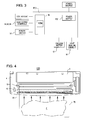
- FIGS. 1-4 of the drawings there is illustrated an embodiment of a food storage appliance 100 which includes a housing 4, a packaging film compartment 6, a lid 7, a cutting mechanism 8, an elongated vacuum trough 10, an elongated heat sealing element 15 and a vacuum motor 17.
- the housing 4 encloses the packaging film compartment 6 covered by the lid 7 and the cutting mechanism 8 (inside the compartment 6) for cutting a length of packaging film stored on a roll in the packaging film compartment 6.
- the housing 4 includes a vacuum compartment including an elongated vacuum trough 10 for receiving an unsealed end of a food packaging container 75 (see FIG. 4 ) formed from a length of packaging film cut from the roll of packaging film.
- the heat sealing element 15 may be disposed on the housing 4 in front of the vacuum trough 10.
- An elongated sensor 20 is disposed in front of the heat sealing element 15 for detecting moisture or liquid in the food packaging container 75 when one end us inserted into the vacuum trough 10 during an evacuation and sealing operation.
- the sensor 20 generates an electrical signal when moisture or liquid is detected in the food packaging container 75 for controlling the operation of the food storage appliance 100 as described hereinbelow.
- the food preservation containers 75 may be pre-formed and sealed on three edges at the factory.
- food packaging containers 75 may be pre-sealed along two edges at the factory and formed into a roll and stored in the packaging film compartment 6 as described for dispensing a length at a time.
- a third edge may be sealed by the user after being cut from the roll by inserting into the vacuum trough 10 and energizing the heat sealing element 15.
- a fully formed food packaging container 75 containing a food item F may be evacuated and sealed on the remaining unsealed end by inserting it into the vacuum trough 10 and energizing the vacuum motor 17 and/or the heat sealing element 15 via electronic controls on the housing 4 as described hereinbelow.
- the electronic controls includes a user interface for controlling various functions of the food storage appliance 100.
- the electronic controls may include exteriorly exposed buttons (switches) 34, 35, 36, and 37 for access by the user.
- the button 34 may operate both the vacuum motor 17 and the heat sealing element 15.
- the button 35 may operate the heat sealing element 15 only.
- the button 36 may operate the vacuum motor 17 only.
- the button 37 may control electrical power being provided to the electronic controls and the electronic components within housing 4 as described below.
- the electronic components may include a microprocessor M mounted on a printed circuit board PC 1 with an operating control program stored in ROM that controls the vacuum motor 17 and the heat sealing element 15, as discussed herein.
- the electronic components may also include other conventional components such as a power circuit PS 1, an input interface circuit (not shown), an output interface circuit (not shown), and one or more storage devices ME, such as a ROM (Read Only Memory) device and a RAM (Random Access Memory) device.
- the power circuit PS1 is connected to an AC or DC power source and directs power to the motors, switches, sensors, etc. described herein, as well as provide power to other circuits and components of the electronic controls.
- the input interface circuit can be electrically connected to the buttons 34, 35, 36 and 37 for user control.
- the output interface circuit can be electrically connected to a LCD screen.
- the storage device ME stores processing results and control programs that are run by the microprocessor circuit M.
- the electronic controls are capable of selectively controlling any of the vacuum motor 17 and the heat sealing element 10 in accordance with the control program. It will be apparent to those skilled in the art from this disclosure that the precise structure and algorithms for the control panel can be any combination of hardware and software that will carry out the functions of the present invention.
- the sensor 20 includes two elongated electrically conductive traces 21, 22 disposed adjacent one another etched onto a non-conductive substrate S.
- the traces 21, 22 may be comprised of a conductive material such as metal including but not limited to copper, gold, silver and aluminum.
- the traces 21, 22 are spaced apart from one another a small distance D1 forming a dielectric barrier therebetween.
- One of the traces 21 is a transmitting antenna fed a signal by the microprocessor M.
- the other trace 22 is a receiving antenna that receives electromagnetic signals generated by trace 21 and feeds the received signal back to the microprocessor M.
- Each of the traces 21, 22 have discrete appendages 21a, 22a extending perpendicularly therefrom along their length at equally spaced intervals such that the appendages 21a, 22a interleave with one another but spaced at a small distance D2 apart forming a dielectric barrier.
- the microprocessor M normally when electrical power to the food storage machine 100 is turned on at button 37, the microprocessor M generates no signal or a weak signal provided to trace 21 and appendages 21a. As such, no signal or a weak signal is transmitted by the trace 21 and appendages 21a and no signal or a very weak signal is received by the trace 22 and appendages 22a. This signal or current in trace 21 and appendages 21a generates a corresponding electric field in the vicinity thereof. Still, because of the dielectric barrier between trace 21 and appendages 21a and trace 22 and appendages 22a, no signal or a very weak signal is received by trace 22 and appendages 22a.
- any liquid present in the food preservation container 75 during the evacuation operation is drawn towards the vacuum trough 10, it must pass over the traces 21, 22 and appendages 21a and 22a.
- the presence of the liquid in the spaces between the traces 21, 22 and appendages 21a and 22a changes the permittivity of air in the spaces. This reduced permittivity allows the electric field created by the weak signal provided to trace 21 and appendages 21a to induce a current or increases signal strength in trace 22 and appendages 22a.
- This induced current or received signal is provided to the microprocessor M which compares the signal to a threshold signal level. If the received signal is equal to or greater than the threshold signal level, this means that there is liquid in the food preservation container 75 about to be drawn into the vacuum trough 10.
- the microprocessor M may use this signal to modify control programs for the vacuum motor 17 and the heat sealing element 15. For example, upon detecting the presence of liquid in the food preservation container 75 the microprocessor M may automatically extend the amount of time the heat sealing element 15 is energized to improve seal quality. This minimizes or eliminates the need for a liquid drip tray in the vacuum trough 10. Alternately, the microprocessor M may shut off or slow the vacuum motor 17 so liquid is drawn more slowly or prevented from being drawn from the food preservation container 75 into the vacuum trough.
- the foregoing examples are not meant to be limiting as other possible modifications to the evacuating and sealing operations are possible.
Abstract
Description
- The present application claims the benefit of
U.S. Provisional Patent Application No. 62/036,384 filed August 12, 2014 - The invention relates to food preservation, and more particularly to an improved food storage appliance having a sensor to detect liquid in a food storage container before the liquid is drawn into the vacuum trough.
- Vacuum packaging appliances that evacuate air from containers holding food are becoming increasingly popular with households for food preservation and storage. The removal of the air delays spoilage and extends the life of the food. The appliances are typically used in conjunction with bag material that constitutes the container holding the food. After the food is inserted in the storage bag, the storage bag is fully sealed by applying heat and pressure to the remaining cut edges. A vacuum may be applied to evacuate air from the storage bag before it is fully sealed. Liquid in the storage bag is typically drawn into the appliance and may be directed into a cavity or a tray for discarding later.
- In an embodiment, there is provided a food storage appliance including a housing, an elongated vacuum trough disposed in the housing, one or more electronic components including a vacuum motor fluidly connected to the vacuum trough and a heat sealing element disposed in proximity of the vacuum trough, an sensor disposed on the housing in proximity to the vacuum trough configured to generate an electrical signal if liquid is detected in a food storage container, the food storage container having a portion inserted into the vacuum trough prior to an evacuation operation, the sensor detecting liquid before it is drawn into the vacuum trough during the evacuation operation, and an integrated electronic circuit connected to the sensor configured to receive the electrical signal and configured to control one of the vacuum motor or the heat sealing element when liquid is detected in the food storage container.
- In an embodiment, there is provided a sensor for a food preservation appliance for detecting liquid in a food preservation container being processed by the food preservation appliance including a substrate comprised of a non-conducting material, a first trace comprised of a conducting material etched onto to the substrate having a plurality of first appendages extending perpendicularly therefrom and spaced along a lineal length of the first trace, a second trace comprised of a conducting material etched onto the substrate separated from the first trace by a first space, the second trace having a plurality of second appendages extending perpendicularly therefrom and spaced along a lineal length of the second trace, the second plurality of appendages interleaved with and separated by a second space from the first plurality of appendages, and a logic circuit electrically connected to the first and second traces, the logic circuit providing a first signal to the first trace and receiving a second signal from the second trace when liquid being evacuated from within the food preservation container by the food preservation appliance is disposed in proximity to the first and second spaces.
- In an embodiment, there is provided a method of storing and preserving food in a food storage container using a food storage including the steps of: inserting a portion of the food storage container into a vacuum trough of the food storage machine, commencing evacuating the food storage container using a vacuum motor disposed in the food storage machine fluidly connected to the vacuum trough, using a sensor to generate a signal if liquid is detected in the food storage container prior to the liquid being drawn into the vacuum trough, using a logic circuit to compare the generated signal to a threshold signal, and using the logic circuit to control one or both of the vacuum motor evacuating the food container or a heat sealing element disposed in proximity of the vacuum trough to heat seal the food storage container.
- A more complete understanding of the present invention, and the attendant advantages and features thereof, will be more readily understood by reference to the following detailed description when considered in conjunction with the accompanying drawings wherein:
-
FIG. 1 is a perspective view of an embodiment of a food storage appliance; -
FIG. 2 is an elevated front perspective view of the food storage appliance ofFIG. 1 ; -
FIG. 3 is a block diagram of the major electronic components of the food storage appliance ofFIG. 1 ; -
FIG. 4 is an illustration showing the intended use of the food storage appliance ofFIG. 1 ; -
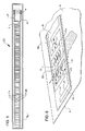
FIG. 5 is an illustration of a sensor for detecting liquids for use with the food storage appliance ofFIG. 1 ; and -
FIG. 6 is an illustration of the operation of the sensor ofFIG. 5 . - Referring now to
FIGS. 1-4 of the drawings, there is illustrated an embodiment of afood storage appliance 100 which includes ahousing 4, a packaging film compartment 6, alid 7, acutting mechanism 8, anelongated vacuum trough 10, an elongatedheat sealing element 15 and avacuum motor 17. Thehousing 4 encloses the packaging film compartment 6 covered by thelid 7 and the cutting mechanism 8 (inside the compartment 6) for cutting a length of packaging film stored on a roll in the packaging film compartment 6. Thehousing 4 includes a vacuum compartment including anelongated vacuum trough 10 for receiving an unsealed end of a food packaging container 75 (seeFIG. 4 ) formed from a length of packaging film cut from the roll of packaging film. Theheat sealing element 15 may be disposed on thehousing 4 in front of thevacuum trough 10. Anelongated sensor 20 is disposed in front of theheat sealing element 15 for detecting moisture or liquid in thefood packaging container 75 when one end us inserted into thevacuum trough 10 during an evacuation and sealing operation. Thesensor 20 generates an electrical signal when moisture or liquid is detected in thefood packaging container 75 for controlling the operation of thefood storage appliance 100 as described hereinbelow. - In an embodiment, the
food preservation containers 75 may be pre-formed and sealed on three edges at the factory. Alternately,food packaging containers 75 may be pre-sealed along two edges at the factory and formed into a roll and stored in the packaging film compartment 6 as described for dispensing a length at a time. A third edge may be sealed by the user after being cut from the roll by inserting into thevacuum trough 10 and energizing theheat sealing element 15. In either scenario, a fully formedfood packaging container 75 containing a food item F may be evacuated and sealed on the remaining unsealed end by inserting it into thevacuum trough 10 and energizing thevacuum motor 17 and/or theheat sealing element 15 via electronic controls on thehousing 4 as described hereinbelow. - In particular, the electronic controls includes a user interface for controlling various functions of the
food storage appliance 100. The electronic controls may include exteriorly exposed buttons (switches) 34, 35, 36, and 37 for access by the user. For example, thebutton 34 may operate both thevacuum motor 17 and theheat sealing element 15. Alternately, thebutton 35 may operate theheat sealing element 15 only. Alternately, thebutton 36 may operate thevacuum motor 17 only. Finally, thebutton 37 may control electrical power being provided to the electronic controls and the electronic components withinhousing 4 as described below. - Within the
housing 4, the electronic components may include a microprocessor M mounted on a printed circuit board PC 1 with an operating control program stored in ROM that controls thevacuum motor 17 and theheat sealing element 15, as discussed herein. The electronic components may also include other conventional components such as apower circuit PS 1, an input interface circuit (not shown), an output interface circuit (not shown), and one or more storage devices ME, such as a ROM (Read Only Memory) device and a RAM (Random Access Memory) device. The power circuit PS1 is connected to an AC or DC power source and directs power to the motors, switches, sensors, etc. described herein, as well as provide power to other circuits and components of the electronic controls. The input interface circuit can be electrically connected to thebuttons vacuum motor 17 and theheat sealing element 10 in accordance with the control program. It will be apparent to those skilled in the art from this disclosure that the precise structure and algorithms for the control panel can be any combination of hardware and software that will carry out the functions of the present invention. - Referring now to
FIGS. 5 and 6 , there is illustrated an embodiment of a liquid ormoisture sensor 20 that is electrically connected to a logic circuit or an integrated circuit such as the microprocessor M described above. Thesensor 20 includes two elongated electricallyconductive traces traces traces traces 21 is a transmitting antenna fed a signal by the microprocessor M. Theother trace 22 is a receiving antenna that receives electromagnetic signals generated bytrace 21 and feeds the received signal back to the microprocessor M. Each of thetraces discrete appendages appendages - In an embodiment, normally when electrical power to the
food storage machine 100 is turned on atbutton 37, the microprocessor M generates no signal or a weak signal provided to trace 21 andappendages 21a. As such, no signal or a weak signal is transmitted by thetrace 21 andappendages 21a and no signal or a very weak signal is received by thetrace 22 andappendages 22a. This signal or current intrace 21 andappendages 21a generates a corresponding electric field in the vicinity thereof. Still, because of the dielectric barrier betweentrace 21 andappendages 21a and trace 22 andappendages 22a, no signal or a very weak signal is received bytrace 22 andappendages 22a. - If any liquid present in the
food preservation container 75 during the evacuation operation is drawn towards thevacuum trough 10, it must pass over thetraces traces appendages appendages 21a to induce a current or increases signal strength intrace 22 andappendages 22a. This induced current or received signal is provided to the microprocessor M which compares the signal to a threshold signal level. If the received signal is equal to or greater than the threshold signal level, this means that there is liquid in thefood preservation container 75 about to be drawn into thevacuum trough 10. The microprocessor M may use this signal to modify control programs for thevacuum motor 17 and theheat sealing element 15. For example, upon detecting the presence of liquid in thefood preservation container 75 the microprocessor M may automatically extend the amount of time theheat sealing element 15 is energized to improve seal quality. This minimizes or eliminates the need for a liquid drip tray in thevacuum trough 10. Alternately, the microprocessor M may shut off or slow thevacuum motor 17 so liquid is drawn more slowly or prevented from being drawn from thefood preservation container 75 into the vacuum trough. The foregoing examples are not meant to be limiting as other possible modifications to the evacuating and sealing operations are possible. - It will be appreciated by persons skilled in the art that the present invention is not limited to what has been particularly shown and described herein above. In addition, unless mention was made above to the contrary, it should be noted that all of the accompanying drawings are not to scale. A variety of modifications and variations are possible in light of the above teachings without departing from the scope and spirit of the invention, which is limited only by the following claims. A similar or nearly identical food preservation appliance is disclosed in
U.S. patent application serial no. 14/126,692 filed December 16, 2013
Claims (17)
- A food storage appliance, comprising:a housing;an elongated vacuum trough disposed in the housing;one or more electronic components including a vacuum motor fluidly connected to the vacuum trough and a heat sealing element disposed in proximity of the vacuum trough;a sensor disposed on the housing in proximity to the vacuum trough configured to generate an electrical signal if liquid is detected in a food storage container, the food storage container having a portion inserted into the vacuum trough prior to an evacuation operation, the sensor detecting liquid before it is drawn into the vacuum trough during the evacuation operation; andan integrated electronic circuit connected to the sensor configured to receive the electrical signal and configured to control one of the vacuum motor or the heat sealing element when liquid is detected in the food storage container.
- The food storage appliance of claim 1, further including the integrated electronic circuit being a microprocessor.
- The food storage appliance of claim 1, the sensor further including:an elongated non-conducting substrate having an elongated first electrical trace having a first plurality of appendages formed thereon operating as a transmitting antenna spaced apart from an elongated second electrical trace formed thereon with a second plurality of appendages operating as a receiving antenna interleaved with and spaced apart from the first plurality of appendages,wherein the first electrical trace and the first plurality of appendages transmits an electrical signal that is received by the second electrical trace and the second plurality of appendages if liquid in the food storage container is brought into the space between the first plurality of appendages and the second plurality of appendages during the evacuation operation.
- The food storage appliance of claim 3, wherein a time the heat sealing element is energized for heat sealing is controlled by the integrated electronic circuit and dependent upon whether the second electrical trace and the second plurality of appendages receive the electrical signal above a threshold signal strength from the first electrical trace and the first plurality of appendages.
- A sensor for a food preservation appliance for detecting liquid in a food preservation container being processed by the food preservation appliance, comprising:a substrate comprised of a non-conducting material;a first trace comprised of a conducting material etched onto to the substrate having a plurality of first appendages extending perpendicularly therefrom and spaced along a lineal length of the first trace;a second trace comprised of a conducting material etched onto the substrate separated from the first trace by a first space, the second trace having a plurality of second appendages extending perpendicularly therefrom and spaced along a lineal length of the second trace, the second plurality of appendages interleaved with and separated by a second space from the first plurality of appendages; anda logic circuit electrically connected to the first and second traces, the logic circuit providing a first signal to the first trace and receiving a second signal from the second trace when liquid being evacuated from within the food preservation container by the food preservation appliance is disposed in proximity to the first and second spaces.
- The sensor of claim 5, wherein the first trace and the first plurality of appendages are a transmitting antenna.
- The sensor of claim 5, wherein the second trace and the second plurality of appendages are a receiving antenna
- The sensor of claim 5, the first trace, the first plurality of appendages, the second trace and the second plurality of appendages being comprised of metal.
- The sensor of claim 8, wherein the metal is selected from the group consisting of copper, silver, aluminum and gold.
- The sensor of claim 5, wherein the logic circuit is an integrated circuit which compares the first signal with the second signal and based on a determined differential controls processing of the food preservation container by the food preservation appliance.
- The sensor of claim 5, wherein the logic circuit is a microprocessor which compares the first signal with the second signal and if the second signal meets a threshold signal strength generates a control signal to control processing of the food preservation container by the food preservation appliance.
- A method of storing and preserving food in a food storage container using a food storage machine, comprising:inserting a portion of the food storage container into a vacuum trough of the food storage machine;commence evacuating the food storage container using a vacuum motor disposed in the food storage machine fluidly connected to the vacuum trough;using a sensor to generate a signal if liquid is detected in the food storage container prior to the liquid being drawn into the vacuum trough;using a logic circuit to compare the generated signal to a threshold signal; andusing the logic circuit to control one or both of the vacuum motor evacuating the food container or a heat sealing element disposed in proximity of the vacuum trough to heat seal the food storage container if the generated signal is above the threshold signal.
- The method of claim 12, further including selecting the sensor to include:a substrate comprised of a non-conducting material;a first trace comprised of a conducting material etched onto the substrate having a plurality of first appendages extending perpendicularly therefrom and spaced along a lineal length of the first trace; anda second trace comprised of a conducting material etched onto the substrate separated from the first trace by a first space, the second trace having a plurality of second appendages extending perpendicularly therefrom and spaced along a lineal length of the second trace, the second plurality of appendages interleaved with and separated by a second space from the first plurality of appendages.
- The method of claim 12, further including selecting the logic circuit to be an integrated circuit or a microprocessor.
- The method of claim 13, whereby the first trace and the plurality of first appendages are a transmitting antenna.
- The method of claim 13, whereby the second trace and the plurality of second appendages are a receiving antenna.
- The method of claim 13, further including selecting the conducting material from the group consisting of copper, silver, aluminum and gold.
Applications Claiming Priority (1)
| Application Number | Priority Date | Filing Date | Title |
|---|---|---|---|
| US201462036384P | 2014-08-12 | 2014-08-12 |
Publications (2)
| Publication Number | Publication Date |
|---|---|
| EP2985233A1 true EP2985233A1 (en) | 2016-02-17 |
| EP2985233B1 EP2985233B1 (en) | 2017-03-22 |
Family
ID=54007445
Family Applications (1)
| Application Number | Title | Priority Date | Filing Date |
|---|---|---|---|
| EP15002404.0A Not-in-force EP2985233B1 (en) | 2014-08-12 | 2015-08-12 | Food storage appliance with moisture sensor |
Country Status (2)
| Country | Link |
|---|---|
| US (1) | US20160047786A1 (en) |
| EP (1) | EP2985233B1 (en) |
Cited By (1)
| Publication number | Priority date | Publication date | Assignee | Title |
|---|---|---|---|---|
| WO2017021557A1 (en) | 2015-08-06 | 2017-02-09 | Multivac Sepp Haggenmüller Se & Co. Kg | Packaging machine having moisture sensor |
Families Citing this family (2)
| Publication number | Priority date | Publication date | Assignee | Title |
|---|---|---|---|---|
| CN107539524B (en) * | 2017-09-07 | 2023-12-29 | 广州亚俊氏电器有限公司 | Vacuum packaging machine |
| CN108510675B (en) * | 2018-03-29 | 2021-01-22 | 京东方科技集团股份有限公司 | Commodity storage method, shopping cart and computer readable storage medium |
Citations (2)
| Publication number | Priority date | Publication date | Assignee | Title |
|---|---|---|---|---|
| US20050022474A1 (en) * | 2003-07-31 | 2005-02-03 | Albritton Charles Wade | Heat sealing element and control of same |
| US20050166671A1 (en) * | 2004-02-03 | 2005-08-04 | Peterson Gregory A. | Liquid level sensor for appliance and associated method |
Family Cites Families (19)
| Publication number | Priority date | Publication date | Assignee | Title |
|---|---|---|---|---|
| US4461167A (en) * | 1981-10-05 | 1984-07-24 | The United States Of America As Represented By The Secretary Of Agriculture | Psychrometer for measuring the humidity of a gas flow |
| US5655357A (en) * | 1995-05-02 | 1997-08-12 | Tilia International, Inc. | Exhaust flow rate vacuum sensor |
| US5765608A (en) * | 1995-11-08 | 1998-06-16 | Tilia International | Hand held vacuum device |
| WO1998029309A1 (en) * | 1996-12-23 | 1998-07-09 | Vacupanel, Inc. | Vacuum insulated panel, container and production method |
| US6106449A (en) * | 1996-12-23 | 2000-08-22 | Vacupanel, Inc. | Vacuum insulated panel and container and method of production |
| US6090422A (en) * | 1999-08-11 | 2000-07-18 | Taragan; Arie | Refrigerator with automatic vacuum compartment and method of preserving fresh food items using the same |
| TW507073B (en) * | 2000-03-31 | 2002-10-21 | Tdk Corp | Humidity sensor and method for making |
| US20030046907A1 (en) * | 2001-08-08 | 2003-03-13 | Costello Anthony William | Packaging apparatus |
| US7131250B2 (en) * | 2002-10-04 | 2006-11-07 | Jcs/Thg, Llp | Appliance for vacuum sealing food containers |
| US7021027B2 (en) * | 2003-07-29 | 2006-04-04 | Tilia International, Inc. | Vacuum pump control and vacuum feedback |
| US7127875B2 (en) * | 2004-10-19 | 2006-10-31 | Intelli Innovations Ltd. | Portable vacuum device |
| US8096329B2 (en) * | 2007-06-15 | 2012-01-17 | S. C. Johnson & Son, Inc. | Hand-held vacuum pump |
| US7891159B2 (en) * | 2008-05-30 | 2011-02-22 | Cryovac, Inc. | Method for positioning a loaded bag in a vacuum chamber |
| FR2934051B1 (en) * | 2008-07-16 | 2011-12-09 | Commissariat Energie Atomique | NANOPOROUS HYDROPHILIC DIELECTRIC HUMIDITY DETECTOR |
| US9422073B2 (en) * | 2011-04-12 | 2016-08-23 | Sunbeam Products, Inc. | Vacuum packaging appliance with roll storage |
| WO2013059775A1 (en) * | 2011-10-21 | 2013-04-25 | Sunbeam Products, Inc. | Vacuum packaging and sealing appliance with double seal |
| US9676506B2 (en) * | 2012-10-19 | 2017-06-13 | Sunbeam Products, Inc. | Vacuum packaging and sealing appliance with liquid detection |
| DE102012220730A1 (en) * | 2012-11-14 | 2014-05-15 | Robert Bosch Gmbh | Tubular bag machine with a Gaseinstellvorrichtung and Gaseinstellvorrichtung for such a bag machine |
| EP3121124B1 (en) * | 2014-01-17 | 2018-12-26 | Electrolux Appliances Aktiebolag | Vacuum packaging arrangement, kitchen cabinet and kitchen furniture |
-
2015
- 2015-08-12 US US14/824,790 patent/US20160047786A1/en not_active Abandoned
- 2015-08-12 EP EP15002404.0A patent/EP2985233B1/en not_active Not-in-force
Patent Citations (2)
| Publication number | Priority date | Publication date | Assignee | Title |
|---|---|---|---|---|
| US20050022474A1 (en) * | 2003-07-31 | 2005-02-03 | Albritton Charles Wade | Heat sealing element and control of same |
| US20050166671A1 (en) * | 2004-02-03 | 2005-08-04 | Peterson Gregory A. | Liquid level sensor for appliance and associated method |
Cited By (1)
| Publication number | Priority date | Publication date | Assignee | Title |
|---|---|---|---|---|
| WO2017021557A1 (en) | 2015-08-06 | 2017-02-09 | Multivac Sepp Haggenmüller Se & Co. Kg | Packaging machine having moisture sensor |
Also Published As
| Publication number | Publication date |
|---|---|
| EP2985233B1 (en) | 2017-03-22 |
| US20160047786A1 (en) | 2016-02-18 |
Similar Documents
| Publication | Publication Date | Title |
|---|---|---|
| EP2985233B1 (en) | Food storage appliance with moisture sensor | |
| US20200293129A1 (en) | Touch sensor assembly and refrigerator door with touch sensor assembly and method for manufacturing the same | |
| US10392146B2 (en) | Food storage appliance with based seal profile | |
| US20180070757A1 (en) | Cooking apparatus and control method thereof | |
| EP1947909A2 (en) | Pan Sensor and Heat Generation Unit Having the Pan Sensor and Cooking Range Having the Heat Generation Unit and Control Method Thereof | |
| EP2862451B1 (en) | Machine for the production and dispensing of ice cream and the like, with improved control system | |
| EP3639676B1 (en) | Defrosting apparatus with repositionable electrode | |
| EP4068907A1 (en) | Cooking appliance, method for controlling cooking appliance, and cooking system | |
| JP5187588B2 (en) | Capacitance sensor and capacitance detection method | |
| EP2879465B1 (en) | Microwave oven | |
| JP2007024829A (en) | Temperature detector and high-frequency heater | |
| US11866982B2 (en) | Cooker | |
| WO2015134764A1 (en) | Food preservation appliance with food management system | |
| KR100988094B1 (en) | A controll pannel for a cooker | |
| EP1283661B1 (en) | Humidity sensor and microwave oven including a humidity sensor | |
| WO2020170784A1 (en) | High frequency heating apparatus | |
| CA2288425C (en) | Microwave oven having a microwave detecting device | |
| KR100420532B1 (en) | Method for preventing a microwave range from operating in idling condition | |
| US20230058275A1 (en) | Heating cooking apparatus | |
| US10879895B2 (en) | Sensor device for detecting the presence of an electrically conductive substance in a space region, and applications thereof | |
| KR100392457B1 (en) | Microwave oven and controlling method thereof | |
| KR20150112205A (en) | Microwave heating apparatus | |
| JP6073196B2 (en) | High frequency heating device | |
| KR20110020600A (en) | Control part for microwave oven | |
| JP2002098339A (en) | Microwave oven and heating cooking system |
Legal Events
| Date | Code | Title | Description |
|---|---|---|---|
| PUAI | Public reference made under article 153(3) epc to a published international application that has entered the european phase |
Free format text: ORIGINAL CODE: 0009012 |
|
| 17P | Request for examination filed |
Effective date: 20150812 |
|
| AK | Designated contracting states |
Kind code of ref document: A1 Designated state(s): AL AT BE BG CH CY CZ DE DK EE ES FI FR GB GR HR HU IE IS IT LI LT LU LV MC MK MT NL NO PL PT RO RS SE SI SK SM TR |
|
| AX | Request for extension of the european patent |
Extension state: BA ME |
|
| GRAP | Despatch of communication of intention to grant a patent |
Free format text: ORIGINAL CODE: EPIDOSNIGR1 |
|
| INTG | Intention to grant announced |
Effective date: 20161006 |
|
| STAA | Information on the status of an ep patent application or granted ep patent |
Free format text: STATUS: GRANT OF PATENT IS INTENDED |
|
| GRAS | Grant fee paid |
Free format text: ORIGINAL CODE: EPIDOSNIGR3 |
|
| GRAA | (expected) grant |
Free format text: ORIGINAL CODE: 0009210 |
|
| STAA | Information on the status of an ep patent application or granted ep patent |
Free format text: STATUS: THE PATENT HAS BEEN GRANTED |
|
| AK | Designated contracting states |
Kind code of ref document: B1 Designated state(s): AL AT BE BG CH CY CZ DE DK EE ES FI FR GB GR HR HU IE IS IT LI LT LU LV MC MK MT NL NO PL PT RO RS SE SI SK SM TR |
|
| REG | Reference to a national code |
Ref country code: GB Ref legal event code: FG4D |
|
| REG | Reference to a national code |
Ref country code: CH Ref legal event code: EP |
|
| REG | Reference to a national code |
Ref country code: AT Ref legal event code: REF Ref document number: 877474 Country of ref document: AT Kind code of ref document: T Effective date: 20170415 |
|
| REG | Reference to a national code |
Ref country code: IE Ref legal event code: FG4D |
|
| REG | Reference to a national code |
Ref country code: DE Ref legal event code: R096 Ref document number: 602015001853 Country of ref document: DE |
|
| REG | Reference to a national code |
Ref country code: NL Ref legal event code: MP Effective date: 20170322 |
|
| PG25 | Lapsed in a contracting state [announced via postgrant information from national office to epo] |
Ref country code: HR Free format text: LAPSE BECAUSE OF FAILURE TO SUBMIT A TRANSLATION OF THE DESCRIPTION OR TO PAY THE FEE WITHIN THE PRESCRIBED TIME-LIMIT Effective date: 20170322 Ref country code: FI Free format text: LAPSE BECAUSE OF FAILURE TO SUBMIT A TRANSLATION OF THE DESCRIPTION OR TO PAY THE FEE WITHIN THE PRESCRIBED TIME-LIMIT Effective date: 20170322 Ref country code: NO Free format text: LAPSE BECAUSE OF FAILURE TO SUBMIT A TRANSLATION OF THE DESCRIPTION OR TO PAY THE FEE WITHIN THE PRESCRIBED TIME-LIMIT Effective date: 20170622 Ref country code: GR Free format text: LAPSE BECAUSE OF FAILURE TO SUBMIT A TRANSLATION OF THE DESCRIPTION OR TO PAY THE FEE WITHIN THE PRESCRIBED TIME-LIMIT Effective date: 20170623 Ref country code: LT Free format text: LAPSE BECAUSE OF FAILURE TO SUBMIT A TRANSLATION OF THE DESCRIPTION OR TO PAY THE FEE WITHIN THE PRESCRIBED TIME-LIMIT Effective date: 20170322 |
|
| REG | Reference to a national code |
Ref country code: LT Ref legal event code: MG4D |
|
| REG | Reference to a national code |
Ref country code: AT Ref legal event code: MK05 Ref document number: 877474 Country of ref document: AT Kind code of ref document: T Effective date: 20170322 |
|
| PG25 | Lapsed in a contracting state [announced via postgrant information from national office to epo] |
Ref country code: BG Free format text: LAPSE BECAUSE OF FAILURE TO SUBMIT A TRANSLATION OF THE DESCRIPTION OR TO PAY THE FEE WITHIN THE PRESCRIBED TIME-LIMIT Effective date: 20170622 Ref country code: SE Free format text: LAPSE BECAUSE OF FAILURE TO SUBMIT A TRANSLATION OF THE DESCRIPTION OR TO PAY THE FEE WITHIN THE PRESCRIBED TIME-LIMIT Effective date: 20170322 Ref country code: RS Free format text: LAPSE BECAUSE OF FAILURE TO SUBMIT A TRANSLATION OF THE DESCRIPTION OR TO PAY THE FEE WITHIN THE PRESCRIBED TIME-LIMIT Effective date: 20170322 Ref country code: LV Free format text: LAPSE BECAUSE OF FAILURE TO SUBMIT A TRANSLATION OF THE DESCRIPTION OR TO PAY THE FEE WITHIN THE PRESCRIBED TIME-LIMIT Effective date: 20170322 |
|
| PG25 | Lapsed in a contracting state [announced via postgrant information from national office to epo] |
Ref country code: NL Free format text: LAPSE BECAUSE OF FAILURE TO SUBMIT A TRANSLATION OF THE DESCRIPTION OR TO PAY THE FEE WITHIN THE PRESCRIBED TIME-LIMIT Effective date: 20170322 |
|
| PG25 | Lapsed in a contracting state [announced via postgrant information from national office to epo] |
Ref country code: ES Free format text: LAPSE BECAUSE OF FAILURE TO SUBMIT A TRANSLATION OF THE DESCRIPTION OR TO PAY THE FEE WITHIN THE PRESCRIBED TIME-LIMIT Effective date: 20170322 Ref country code: IT Free format text: LAPSE BECAUSE OF FAILURE TO SUBMIT A TRANSLATION OF THE DESCRIPTION OR TO PAY THE FEE WITHIN THE PRESCRIBED TIME-LIMIT Effective date: 20170322 Ref country code: RO Free format text: LAPSE BECAUSE OF FAILURE TO SUBMIT A TRANSLATION OF THE DESCRIPTION OR TO PAY THE FEE WITHIN THE PRESCRIBED TIME-LIMIT Effective date: 20170322 Ref country code: AT Free format text: LAPSE BECAUSE OF FAILURE TO SUBMIT A TRANSLATION OF THE DESCRIPTION OR TO PAY THE FEE WITHIN THE PRESCRIBED TIME-LIMIT Effective date: 20170322 Ref country code: CZ Free format text: LAPSE BECAUSE OF FAILURE TO SUBMIT A TRANSLATION OF THE DESCRIPTION OR TO PAY THE FEE WITHIN THE PRESCRIBED TIME-LIMIT Effective date: 20170322 Ref country code: EE Free format text: LAPSE BECAUSE OF FAILURE TO SUBMIT A TRANSLATION OF THE DESCRIPTION OR TO PAY THE FEE WITHIN THE PRESCRIBED TIME-LIMIT Effective date: 20170322 Ref country code: SK Free format text: LAPSE BECAUSE OF FAILURE TO SUBMIT A TRANSLATION OF THE DESCRIPTION OR TO PAY THE FEE WITHIN THE PRESCRIBED TIME-LIMIT Effective date: 20170322 |
|
| PG25 | Lapsed in a contracting state [announced via postgrant information from national office to epo] |
Ref country code: PT Free format text: LAPSE BECAUSE OF FAILURE TO SUBMIT A TRANSLATION OF THE DESCRIPTION OR TO PAY THE FEE WITHIN THE PRESCRIBED TIME-LIMIT Effective date: 20170724 Ref country code: IS Free format text: LAPSE BECAUSE OF FAILURE TO SUBMIT A TRANSLATION OF THE DESCRIPTION OR TO PAY THE FEE WITHIN THE PRESCRIBED TIME-LIMIT Effective date: 20170722 Ref country code: PL Free format text: LAPSE BECAUSE OF FAILURE TO SUBMIT A TRANSLATION OF THE DESCRIPTION OR TO PAY THE FEE WITHIN THE PRESCRIBED TIME-LIMIT Effective date: 20170322 Ref country code: SM Free format text: LAPSE BECAUSE OF FAILURE TO SUBMIT A TRANSLATION OF THE DESCRIPTION OR TO PAY THE FEE WITHIN THE PRESCRIBED TIME-LIMIT Effective date: 20170322 |
|
| REG | Reference to a national code |
Ref country code: DE Ref legal event code: R097 Ref document number: 602015001853 Country of ref document: DE |
|
| PLBE | No opposition filed within time limit |
Free format text: ORIGINAL CODE: 0009261 |
|
| STAA | Information on the status of an ep patent application or granted ep patent |
Free format text: STATUS: NO OPPOSITION FILED WITHIN TIME LIMIT |
|
| PG25 | Lapsed in a contracting state [announced via postgrant information from national office to epo] |
Ref country code: DK Free format text: LAPSE BECAUSE OF FAILURE TO SUBMIT A TRANSLATION OF THE DESCRIPTION OR TO PAY THE FEE WITHIN THE PRESCRIBED TIME-LIMIT Effective date: 20170322 |
|
| 26N | No opposition filed |
Effective date: 20180102 |
|
| PG25 | Lapsed in a contracting state [announced via postgrant information from national office to epo] |
Ref country code: SI Free format text: LAPSE BECAUSE OF FAILURE TO SUBMIT A TRANSLATION OF THE DESCRIPTION OR TO PAY THE FEE WITHIN THE PRESCRIBED TIME-LIMIT Effective date: 20170322 |
|
| REG | Reference to a national code |
Ref country code: DE Ref legal event code: R119 Ref document number: 602015001853 Country of ref document: DE |
|
| PG25 | Lapsed in a contracting state [announced via postgrant information from national office to epo] |
Ref country code: MC Free format text: LAPSE BECAUSE OF FAILURE TO SUBMIT A TRANSLATION OF THE DESCRIPTION OR TO PAY THE FEE WITHIN THE PRESCRIBED TIME-LIMIT Effective date: 20170322 |
|
| REG | Reference to a national code |
Ref country code: BE Ref legal event code: MM Effective date: 20170831 |
|
| REG | Reference to a national code |
Ref country code: FR Ref legal event code: ST Effective date: 20180430 |
|
| REG | Reference to a national code |
Ref country code: IE Ref legal event code: MM4A |
|
| PG25 | Lapsed in a contracting state [announced via postgrant information from national office to epo] |
Ref country code: LU Free format text: LAPSE BECAUSE OF NON-PAYMENT OF DUE FEES Effective date: 20170812 |
|
| PG25 | Lapsed in a contracting state [announced via postgrant information from national office to epo] |
Ref country code: IE Free format text: LAPSE BECAUSE OF NON-PAYMENT OF DUE FEES Effective date: 20170812 Ref country code: DE Free format text: LAPSE BECAUSE OF NON-PAYMENT OF DUE FEES Effective date: 20180301 |
|
| PG25 | Lapsed in a contracting state [announced via postgrant information from national office to epo] |
Ref country code: BE Free format text: LAPSE BECAUSE OF NON-PAYMENT OF DUE FEES Effective date: 20170831 Ref country code: FR Free format text: LAPSE BECAUSE OF NON-PAYMENT OF DUE FEES Effective date: 20170831 |
|
| PG25 | Lapsed in a contracting state [announced via postgrant information from national office to epo] |
Ref country code: MT Free format text: LAPSE BECAUSE OF NON-PAYMENT OF DUE FEES Effective date: 20170812 |
|
| REG | Reference to a national code |
Ref country code: CH Ref legal event code: PL |
|
| PG25 | Lapsed in a contracting state [announced via postgrant information from national office to epo] |
Ref country code: LI Free format text: LAPSE BECAUSE OF NON-PAYMENT OF DUE FEES Effective date: 20180831 Ref country code: CH Free format text: LAPSE BECAUSE OF NON-PAYMENT OF DUE FEES Effective date: 20180831 |
|
| PG25 | Lapsed in a contracting state [announced via postgrant information from national office to epo] |
Ref country code: HU Free format text: LAPSE BECAUSE OF FAILURE TO SUBMIT A TRANSLATION OF THE DESCRIPTION OR TO PAY THE FEE WITHIN THE PRESCRIBED TIME-LIMIT; INVALID AB INITIO Effective date: 20150812 |
|
| PG25 | Lapsed in a contracting state [announced via postgrant information from national office to epo] |
Ref country code: CY Free format text: LAPSE BECAUSE OF FAILURE TO SUBMIT A TRANSLATION OF THE DESCRIPTION OR TO PAY THE FEE WITHIN THE PRESCRIBED TIME-LIMIT Effective date: 20170322 |
|
| PG25 | Lapsed in a contracting state [announced via postgrant information from national office to epo] |
Ref country code: MK Free format text: LAPSE BECAUSE OF FAILURE TO SUBMIT A TRANSLATION OF THE DESCRIPTION OR TO PAY THE FEE WITHIN THE PRESCRIBED TIME-LIMIT Effective date: 20170322 |
|
| PG25 | Lapsed in a contracting state [announced via postgrant information from national office to epo] |
Ref country code: TR Free format text: LAPSE BECAUSE OF FAILURE TO SUBMIT A TRANSLATION OF THE DESCRIPTION OR TO PAY THE FEE WITHIN THE PRESCRIBED TIME-LIMIT Effective date: 20170322 |
|
| GBPC | Gb: european patent ceased through non-payment of renewal fee |
Effective date: 20190812 |
|
| PG25 | Lapsed in a contracting state [announced via postgrant information from national office to epo] |
Ref country code: AL Free format text: LAPSE BECAUSE OF FAILURE TO SUBMIT A TRANSLATION OF THE DESCRIPTION OR TO PAY THE FEE WITHIN THE PRESCRIBED TIME-LIMIT Effective date: 20170322 |
|
| PG25 | Lapsed in a contracting state [announced via postgrant information from national office to epo] |
Ref country code: GB Free format text: LAPSE BECAUSE OF NON-PAYMENT OF DUE FEES Effective date: 20190812 |