EP2985070A1 - Membrane cartridge, and membrane-cartridge production method - Google Patents
Membrane cartridge, and membrane-cartridge production method Download PDFInfo
- Publication number
- EP2985070A1 EP2985070A1 EP14775284.4A EP14775284A EP2985070A1 EP 2985070 A1 EP2985070 A1 EP 2985070A1 EP 14775284 A EP14775284 A EP 14775284A EP 2985070 A1 EP2985070 A1 EP 2985070A1
- Authority
- EP
- European Patent Office
- Prior art keywords
- membrane
- filtration
- plate
- filtration plate
- filtration membrane
- Prior art date
- Legal status (The legal status is an assumption and is not a legal conclusion. Google has not performed a legal analysis and makes no representation as to the accuracy of the status listed.)
- Granted
Links
Images



Classifications
-
- B—PERFORMING OPERATIONS; TRANSPORTING
- B01—PHYSICAL OR CHEMICAL PROCESSES OR APPARATUS IN GENERAL
- B01D—SEPARATION
- B01D63/00—Apparatus in general for separation processes using semi-permeable membranes
- B01D63/08—Flat membrane modules
- B01D63/081—Manufacturing thereof
-
- B—PERFORMING OPERATIONS; TRANSPORTING
- B01—PHYSICAL OR CHEMICAL PROCESSES OR APPARATUS IN GENERAL
- B01D—SEPARATION
- B01D63/00—Apparatus in general for separation processes using semi-permeable membranes
- B01D63/08—Flat membrane modules
- B01D63/082—Flat membrane modules comprising a stack of flat membranes
-
- B—PERFORMING OPERATIONS; TRANSPORTING
- B01—PHYSICAL OR CHEMICAL PROCESSES OR APPARATUS IN GENERAL
- B01D—SEPARATION
- B01D65/00—Accessories or auxiliary operations, in general, for separation processes or apparatus using semi-permeable membranes
- B01D65/003—Membrane bonding or sealing
-
- B—PERFORMING OPERATIONS; TRANSPORTING
- B01—PHYSICAL OR CHEMICAL PROCESSES OR APPARATUS IN GENERAL
- B01D—SEPARATION
- B01D69/00—Semi-permeable membranes for separation processes or apparatus characterised by their form, structure or properties; Manufacturing processes specially adapted therefor
- B01D69/06—Flat membranes
-
- C—CHEMISTRY; METALLURGY
- C02—TREATMENT OF WATER, WASTE WATER, SEWAGE, OR SLUDGE
- C02F—TREATMENT OF WATER, WASTE WATER, SEWAGE, OR SLUDGE
- C02F3/00—Biological treatment of water, waste water, or sewage
- C02F3/02—Aerobic processes
- C02F3/12—Activated sludge processes
- C02F3/1236—Particular type of activated sludge installations
- C02F3/1268—Membrane bioreactor systems
- C02F3/1273—Submerged membrane bioreactors
-
- B—PERFORMING OPERATIONS; TRANSPORTING
- B01—PHYSICAL OR CHEMICAL PROCESSES OR APPARATUS IN GENERAL
- B01D—SEPARATION
- B01D2313/00—Details relating to membrane modules or apparatus
- B01D2313/04—Specific sealing means
- B01D2313/042—Adhesives or glues
-
- B—PERFORMING OPERATIONS; TRANSPORTING
- B01—PHYSICAL OR CHEMICAL PROCESSES OR APPARATUS IN GENERAL
- B01D—SEPARATION
- B01D2315/00—Details relating to the membrane module operation
- B01D2315/06—Submerged-type; Immersion type
-
- B—PERFORMING OPERATIONS; TRANSPORTING
- B01—PHYSICAL OR CHEMICAL PROCESSES OR APPARATUS IN GENERAL
- B01D—SEPARATION
- B01D2323/00—Details relating to membrane preparation
- B01D2323/42—Details of membrane preparation apparatus
-
- B—PERFORMING OPERATIONS; TRANSPORTING
- B01—PHYSICAL OR CHEMICAL PROCESSES OR APPARATUS IN GENERAL
- B01D—SEPARATION
- B01D61/00—Processes of separation using semi-permeable membranes, e.g. dialysis, osmosis or ultrafiltration; Apparatus, accessories or auxiliary operations specially adapted therefor
- B01D61/14—Ultrafiltration; Microfiltration
- B01D61/18—Apparatus therefor
-
- Y—GENERAL TAGGING OF NEW TECHNOLOGICAL DEVELOPMENTS; GENERAL TAGGING OF CROSS-SECTIONAL TECHNOLOGIES SPANNING OVER SEVERAL SECTIONS OF THE IPC; TECHNICAL SUBJECTS COVERED BY FORMER USPC CROSS-REFERENCE ART COLLECTIONS [XRACs] AND DIGESTS
- Y02—TECHNOLOGIES OR APPLICATIONS FOR MITIGATION OR ADAPTATION AGAINST CLIMATE CHANGE
- Y02W—CLIMATE CHANGE MITIGATION TECHNOLOGIES RELATED TO WASTEWATER TREATMENT OR WASTE MANAGEMENT
- Y02W10/00—Technologies for wastewater treatment
- Y02W10/10—Biological treatment of water, waste water, or sewage
Definitions
- the present invention relates to a membrane cartridge and a method for producing a membrane cartridge.
- An immersion-type membrane separation device is suitably used as a solid-liquid separation device in a facility for water treatment such as wastewater purification treatment.
- the immersion-type membrane separation device contains a plurality of flat-plate membrane cartridges each of which includes a filtration plate made of a resin and a filtration membrane provided on both sides of the filtration plate and joined thereto at a periphery thereof.
- Patent Reference 1 discloses a method for producing a membrane module aiming at preventing bonding unevenness of a filtration membrane to a filtration plate, improving bonding efficiency, and thereby securing the airtightness of the membrane module, by covering a surface of an organic material membrane support body with an organic filtration membrane, and thermally bonding the periphery of the organic filtration membrane to the membrane supporting body by local heating.
- Patent Reference 2 proposes an immersion-type membrane cartridge production method in order to provide a producing method for an immersion-type membrane cartridge having an improved durability against aeration.
- the production method of the immersion-type membrane cartridge includes forming on a filtration plate made of a resin double-lined sealing portions and a band-like auxiliary portion which protrude from a surface of the filtration plate and are integrally formed along the periphery of the filtration plate to make a perimeter, wherein an inside sealing portion has a profile lower than that of an outside sealing portion, and the outside sealing portion and the auxiliary portion have the same height.
- the method further includes disposing a filtration membrane over the surface of the filtration plate so as to cover both of the sealing portions and the auxiliary portion, pressing an up-down horn onto the sealing portions and the auxiliary portion over the filtration membrane, and emitting ultrasonic waves so as to weld the filtration membrane at the sealing portions and the auxiliary portion, thereby forming a liner water stopping portion at the sealing portions so as to maintain the filtration membrane in a tension state, while forming an auxiliary welding portion at the auxiliary portion.
- Patent Reference 3 discloses a membrane cartridge including a support body of a non-woven fabric made of plastic fiber and a microporous filtration membrane bonded onto a smooth surface in a periphery of a filtration plate made of a thermoplastic resin, intending to obtain a membrane cartridge capable of replacing the filtration membrane by reusing the thermoplastic filtration plate when the membrane has broken or deteriorated.
- the bonding surface of the filtration membrane onto the filtration plate is a plane parallel to the surface of the filtration plate.
- a filtration membrane in a plate-like membrane cartridge, is clinging to a filtration plate by a suction pressure or a natural water head pressure during a filtration operation, is trembling in a slightly bulged state during a relaxation in which only air diffusion is performed without filtration operation, and is kept in a bulged state during a clearing operation under a reversed pressure in which a chemical solution or clear water is injected from the secondary side of the filtration membrane.
- the suction pressure during the filtration operation is rather small and in a range of 10 kPa, and the membrane cartridge vibrates vigorously due to an upward flow accompanying the air diffusion from below. Accordingly, the filtration membrane may not perfectly follow the vibration of the filtration plate, but is repeatedly separating from and coming into contact with the filtration plate.
- Patent Reference 2 described above discloses a filtration plate structure in which the double-lined sealing portions and the band-like auxiliary portion are formed integrally on the filtration plate along the periphery thereof so as to protrude from the surface of the filtration plate to make the perimeter thereof, where the inside sealing portion has the profile lower than that of the outside sealing portion.
- an object of the present invention is to provide a low-cost membrane cartridge and a low-cost method for producing a membrane cartridge in which fatigue durability can be increased with a simple structure, by focusing on a bonding position of the filtration membrane onto the filtration plate.
- a first characteristic construction of a membrane cartridge in accordance with the present invention as described in claim 1 is that the membrane cartridge has a filtration plate made of a thermoplastic resin and a filtration membrane disposed on a surface of the filtration plate, where a joining portion of the filtration membrane provided at a periphery thereof is joined to the filtration plate, and that at least an inner edge portion of the joining portion has a downward inclination with respect to the surface of the filtration plate inside of the inner edge portion toward an outer peripheral edge of the filtration membrane.
- the same bulging state of the filtration membrane has a smaller bulging angle with respect to the inclined inner edge portion, compared with an inner edge portion parallel to or flush with the surface of the filtration plate inside thereof, thereby reducing a bending stress affecting the joining portion of the filtration membrane so as to increase a fatigue durability thereof.
- a second characteristic construction of the membrane cartridge in accordance with the present invention as described in claim 2 is, in addition to the first characteristic construction described above, that the downward inclination is equal to or greater than 10 degrees and equal to or smaller than 50 degrees.
- a third characteristic construction of the membrane cartridge in accordance with the present invention as described in claim 3 is, in addition to the first characteristic construction described above, that the downward inclination is equal to or greater than 15 degrees and equal to or smaller than 35 degrees.
- a first characteristic construction of a method for producing a membrane cartridge in accordance with the present invention as described in claim 4 is that the method produces the membrane cartridge having a filtration plate made of a thermoplastic resin and a filtration membrane disposed on a surface of the filtration plate, where a joining portion of the filtration membrane provided at a periphery thereof is joined to the filtration plate, and that the filtration membrane is joined by pressing a pressing tool onto the filtration plate with the periphery of the filtration membrane sandwiched therebetween, the pressing tool having such a slope that at least an inner edge portion of the joining portion is provided with a downward inclination with respect to the surface of the filtration plate inside of the inner edge portion toward an outer peripheral edge of the filtration membrane.
- a heating plate, an ultrasonic hone, or the like can be used as the pressing tool, and when the periphery of the filtration membrane is joined to the partially softened or melted filtration plate by an operation of the slope formed on the pressing tool, the downward inclination with respect to the surface of the filtration plate inside of the inner edge portion toward the outer peripheral edge of the filtration membrane is formed in the inner edge portion of the joining portion.
- a second characteristic construction of the method of producing the membrane cartridge in accordance with the present invention as described in claim 5 is, in addition to the first characteristic construction described above, that the surface of the filtration plate corresponding to the joining portion is not downwardly inclined before the joining process is performed.
- the surface of the filtration plate corresponding to the joining portion does not have the downward inclination before the joining process and then is formed into a downward inclination by the joining process, even if the joining conditions fluctuate, for example, the temperature applied to the filtration plate from the heating plate, ultrasonic hone, or the like might vary, an amount of thermal deformation varies over a width of the joining portion in order to form such a downward inclination through the joining process, an area realizing a sufficient bonding strength between the filtration plate and the filtration membrane can be secured within the width of the joining portion.
- the maximum quantity of heat is applied to the outer edge of the width of the joining portion and the minimum quantity of heat is applied to the inner edge thereof, and thus it is more likely that the sufficient bonding strength is realized in a certain area therebetween.
- a third characteristic construction of the method for producing the membrane cartridge in accordance with the present invention as described in claim 6 is, in addition to the first or second characteristic construction described above, that the slope of the pressing tool is set such that the downward inclination is equal to or greater than 10 degrees and equal to or smaller than 50 degrees.
- a fourth characteristic construction of the method for producing the membrane cartridge in accordance with the present invention as described in claim 7 is, in addition to the first or second characteristic construction described above, that the slope of the pressing tool is set such that the downward inclination is equal to or greater than 15 degrees and equal to or smaller than 35 degrees.
- a wastewater treatment apparatus 1 employing a membrane bioreactor process is provided with a pre-treatment equipment 2, a flow rate adjusting tank 3, a membrane separation tank 4 in which a membrane separation device 6 is immersed, and a treated water tank 5.
- the pre-treatment equipment 2 is provided with a bar screen 2a and the like which removes foreign materials and the like mixed in raw water which becomes water to be treated.
- the flow rate adjusting tank 3 retains the raw water from which foreign materials have been removed by the bar screen 2a and the like.
- a flow rate adjusting mechanism such as a pump or valve, and the like, is provided such that the raw water is stably supplied to the membrane separation tank 4 from the flow rate adjusting tank 3 at a constant flow rate even if the raw water inflow fluctuates.
- the membrane separation tank 4 which is filled with activated sludge
- organic matter contained in the raw water is decomposed by the biological treatment by the activated sludge, and permeated water which has been filtered via the membrane separation device 6 is guided to the treated water tank 5 in which the permeated water is temporarily stored and then discharged. Excess of the activated sludge which has been multiplied in the membrane separation tank 4 is pulled out therefrom so as to maintain a constant concentration of the activated sludge.
- the membrane separation device 6 is provided with one hundred (100) plate-shaped membrane cartridges 8 disposed in a membrane case 7 having upper and lower open ends such that the membrane surfaces are arranged in respective longitudinal positions and separated from each other with a fixed distance of about 6 mm to 10 mm (8 mm in this embodiment), and with a diffuser device 12 disposed under the membrane case 7.
- the diffuser device 12 is provided with a diffusion pipe 13 having a plurality of diffusion holes, and is connected via a diffusion header 14 coupled to the diffusion pipe 13 to a blower 15 provided outside of the tank.
- a pump 18 as a pressure difference generating mechanism external to the tank is connected to the membrane cartridges 8 via a liquid collection pipe 17, whereby the water to be treated in the tank is sucked and filtered through a membrane of the membrane cartridges 8.
- a filtration membrane 10 is disposed on both of the front and rear faces of a filtration plate 9 made of a thermoplastic resin such as ABS resin having a height of 1000 mm and a width of 490 mm.
- a joining portion 11 of the filtration membrane 11 provided at the periphery thereof is bonded to the filtration plate 9 by ultrasonic or thermal welding, or is adhered thereto using an adhesive.
- the filtration membrane 10 is an organic filtration membrane including a support body 10a formed of a nonwoven fabric made of PET fiber, for example, and a microporous membrane 10b having an average pore diameter of about 0.2 ⁇ m, which is formed by coating and impregnating the support body 10a with a porous resin.
- a plurality of grooves 9b having a depth of about 2 mm and a width of about 2 mm are formed on a surface of the filtration plate 9 along a longitudinal direction, and a horizontal groove 9c is formed at an upper end of the grooves 9b so as to communicate with each of the grooves 9b.
- the front and rear surfaces of the filtration plate 9 have respective horizontal grooves 9c which communicate with each other via a communication hole 9d which in turn communicates with a nozzle 9a formed at an upper edge portion of the filtration plate 9.
- the nozzle 9a is connected to the liquid collection pipe 17 via a respective tube 16, and the pump 18 is connected to the liquid collection pipe 17, such that the permeated water sucked by the pump 18 is transported to the treated water tank 5.
- a filtering operation is performed to obtain the permeated water by passing the water to be treated through the filtration membrane 10.
- a relaxation operation in which only the diffuser device 12 is operated while the pump 18 is stopped is performed regularly, or when the suction pressure during the filtering operation becomes high, in order to prevent fouling of the filtration membrane 10 while maintaining characteristics of the activated sludge in the tank.
- a chemical solution cleaning process for cleaning the filtration membrane 10 by injecting a chemical solution into each membrane cartridge 8 via the liquid collection pipe 17 is performed regularly, or when the suction pressure after the relaxation operation becomes high.
- the membrane cartridge 8 vibrates vigorously during the filtering operation due to an upward flow accompanying the air diffusion from below, whereby the filtration membrane 10 does not follow the vibration of the filtration plate 9 so as to repeatedly cling to and separate from the filtration plate 9.
- the filtration membrane 10 of the membrane cartridge 8 widely trembles in such a state that the filtration membrane 10 is slightly bulged from the filtration plate 9 due to the upward flow accompanying the air diffusion from below.
- the filtration membrane is maintained in a continuously bulged state. For example, in such a chemical cleaning process, the filtration membrane 10 bulges from the filtration plate at the joining portion with a rising angle about 50 degrees.
- the filtration membrane 10 receives a strong stress to the joining portion by changing its position from that clings to the filtration plate 9 to that bulging from the filtration plate 9, and the risk that the filtration membrane raptures or comes off at the joining portion due to fatigue increases when the joining portion is repeatedly subject to such a stress over time.
- the membrane cartridge 8 has a filtration plate 9 and a filtration membrane 10 disposed on the surface of the filtration plate 9, and a joining portion 11 of the filtration membrane 10 provided at a periphery thereof is joined to the filtration plate 9 such that at least an inner edge portion P1 of the joining portion 11 has a downward inclination with respect to the surface P2 of the filtration plate 9 inside of the inner edge portion P1 toward an outer peripheral edge P3 of the filtration membrane 10.
- a bulging angle of the filtration membrane 10 with respect to the inner edge portion P1 i.e., a rising angle ⁇ of the filtration membrane 10(A) indicated by a two-dot chain line with respect to the inner edge portion P1
- a rising angle ⁇ of the filtration membrane 10(A) indicated by a two-dot chain line with respect to the inner edge portion P1 becomes relatively small, compared with such an angle formed with respect to an inner edge portion parallel to or flush with the filtration plate surface P2 inside thereof, thereby reducing a bending stress affecting the joining portion 11 of the filtration membrane 10.
- the entire joining portion 11 may be formed into a downward inclination in the width direction with respect to the filtration plate surface P2 toward the outer peripheral edge P3 of the filtration membrane 10.
- FIG. 4B shows a conventional structure in which the inner edge portion P1 of the joining portion 11 is formed parallel to or flush with the filtration plate surface P2 inside thereof.
- the filtration membrane 10(B) indicated by a two-dot chain line bulges from the filtration plate surface adjacent to the joining portion 11 at a rising angle 2 ⁇
- the structure shown in FIG. 4A is employed, the bending stress would be reduced to that of the rising angle ⁇ , whereby the fatigue durability can be increased.
- the downward inclination is equal to or greater than 10 degrees and equal to or smaller than 50 degrees, and more preferably, the downward inclination is equal to or greater than 15 degrees and equal to or smaller than 35 degrees.
- the width of the downwardly inclined area in the joining portion 11 is preferably in a range between 1 mm and 10 mm.
- the filtration membrane 10 may be welded to the filtration plate 9 by pressing a heating plate heated to a predetermined temperature or an ultrasonic horn onto the filtration plate 9 with the periphery of the filtration membrane 10 sandwiched therebetween.
- a heating plate heated to a predetermined temperature or an ultrasonic horn In addition to the heating plate and ultrasonic horn, a high-temperature gas such as heating steam can be jetted out from a tip of a heating member.
- An adhesive may also be used for bonding the filtration membrane 10 to the filtration plate 9.
- an inclined portion can be formed in advance in an area of the filtration plate 9 which correspond to the inner edge portion of the joining portion such that the inclined portion is downwardly inclined with respect to the surface of the filtration plate 9 toward the outer edge of the filtration membrane 10.
- the heating plate, the ultrasonic horn, or the heating member may have such a slope that at least the inner edge portion is provided with the downward inclination with respect to the surface of the filtration plate inside of the inner edge portion toward the outer peripheral edge of the filtration membrane.
- the filtration membrane 10 can be welded to the filtration plate 9 by pressing a heating plate or ultrasonic horn 20 having a sloped tip portion having a predetermined inclination angle onto the surface of the filtration plate 9 from above.
- a heating plate or ultrasonic horn 20 having a tip portion having a V-shaped cross-section with a predetermined inclination angel can be used.
- a heating plate or ultrasonic horn 20 having a partially sloped tip portion having a slope corresponding to the inner edge portion of the joining portion 11 can also be used such that the remaining portion of the joining portion 11 has a flat surface.
- a heating plate or ultrasonic horn 20 may have a tip portion having a convex cross-section with an inclination angle within a predetermined range.
- FIG. 5A illustrates an example in which a downward inclination inclined with respect to the surface of the filtration plate 9 inside of the inner edge portion of the joining portion 11 toward the outer peripheral edge of the filtration membrane 10 is formed in the inner edge portion by pressing the heating plate or ultrasonic horn 20 onto the filtration plate 9 having a flat surface.
- FIG. 5B illustrates an example in which a downward inclination inclined with respect to the surface of the filtration plate 9 inside of the inner edge portion of the joining portion 11 toward the outer peripheral edge of the filtration membrane 10 is formed in the inner edge portion by pressing the heating plate or ultrasonic horn 20 onto the filtration plate 9 provided with a protrusion having a flat top surface in an area corresponding to the joining portion 11.
- FIG. 5C illustrates an example in which a downward inclination inclined with respect to the surface of the filtration plate 9 inside of the inner edge portion of the joining portion 11 toward the outer peripheral edge of the filtration membrane 10 is formed in the inner edge portion by pressing the heating plate or ultrasonic horn 20 onto the filtration plate 9 provided with a protrusion having an upward inclination toward the outer peripheral edge of the filtration membrane 10 in an area corresponding to the joining portion 11.
- the surface of the filtration plate 9 corresponding to the joining portion 11 does not have a downward inclination before the joining process. Since the surface of the filtration plate 9 corresponding to the joining portion 11 does not have a downward inclination before the joining process and then is formed into a downward inclination through the joining process, even if the joining conditions fluctuate, for example, the temperature applied to the filtration plate 9 from the heating plate or ultrasonic horn 20 varies, an amount of thermal deformation or a time period during which the heating plate or ultrasonic horn is in contact with varies over the width of the joining portion in order to form such a downward inclination through the joining process, an area realizing a sufficient bonding strength between the filtration plate 9 and the filtration membrane 10 can be secured within the width of the joining portion.
- the temperature in the joining portion is equal to or higher than a softening point of the resin constituting the filtration plate and lower than a melting point of the unwoven fabric constituting the filtration membrane, such that the downward slope can be formed in the filtration plate while maintaining the strength of the filtration membrane.
- the preferable temperature is equal to or greater than 150°C and equal to or smaller than 250°C, and the output of the heating plate or ultrasonic horn can be adjusted such that the joining portion has the temperature between 150°C and 250°C.
- the material, size, and thickness of the filtration plate and filtration membrane, the shape of the tip of the heating plate or ultrasonic horn, the joining temperature, and the like are not limited to specific examples, but a design of the specific structure of each part can be changed so long as the function and effect of the present invention can be achieved.
Landscapes
- Chemical & Material Sciences (AREA)
- Chemical Kinetics & Catalysis (AREA)
- Life Sciences & Earth Sciences (AREA)
- Engineering & Computer Science (AREA)
- Biodiversity & Conservation Biology (AREA)
- Microbiology (AREA)
- Hydrology & Water Resources (AREA)
- Environmental & Geological Engineering (AREA)
- Water Supply & Treatment (AREA)
- Organic Chemistry (AREA)
- Manufacturing & Machinery (AREA)
- Separation Using Semi-Permeable Membranes (AREA)
Abstract
Description
- The present invention relates to a membrane cartridge and a method for producing a membrane cartridge.
- An immersion-type membrane separation device is suitably used as a solid-liquid separation device in a facility for water treatment such as wastewater purification treatment. The immersion-type membrane separation device contains a plurality of flat-plate membrane cartridges each of which includes a filtration plate made of a resin and a filtration membrane provided on both sides of the filtration plate and joined thereto at a periphery thereof.
- Patent Reference 1 discloses a method for producing a membrane module aiming at preventing bonding unevenness of a filtration membrane to a filtration plate, improving bonding efficiency, and thereby securing the airtightness of the membrane module, by covering a surface of an organic material membrane support body with an organic filtration membrane, and thermally bonding the periphery of the organic filtration membrane to the membrane supporting body by local heating.
-
Patent Reference 2 proposes an immersion-type membrane cartridge production method in order to provide a producing method for an immersion-type membrane cartridge having an improved durability against aeration. - The production method of the immersion-type membrane cartridge includes forming on a filtration plate made of a resin double-lined sealing portions and a band-like auxiliary portion which protrude from a surface of the filtration plate and are integrally formed along the periphery of the filtration plate to make a perimeter, wherein an inside sealing portion has a profile lower than that of an outside sealing portion, and the outside sealing portion and the auxiliary portion have the same height. The method further includes disposing a filtration membrane over the surface of the filtration plate so as to cover both of the sealing portions and the auxiliary portion, pressing an up-down horn onto the sealing portions and the auxiliary portion over the filtration membrane, and emitting ultrasonic waves so as to weld the filtration membrane at the sealing portions and the auxiliary portion, thereby forming a liner water stopping portion at the sealing portions so as to maintain the filtration membrane in a tension state, while forming an auxiliary welding portion at the auxiliary portion.
-
Patent Reference 3 discloses a membrane cartridge including a support body of a non-woven fabric made of plastic fiber and a microporous filtration membrane bonded onto a smooth surface in a periphery of a filtration plate made of a thermoplastic resin, intending to obtain a membrane cartridge capable of replacing the filtration membrane by reusing the thermoplastic filtration plate when the membrane has broken or deteriorated. - In all of the membrane cartridges disclosed in Patent References 1 through 3, the bonding surface of the filtration membrane onto the filtration plate is a plane parallel to the surface of the filtration plate.
-
- Patent Document 1:
Japanese Patent Laid-Open Application No. H06-218240 - Patent Document 2:
Japanese Patent Laid-Open Application No. 2001-120958 - Patent Document 3:
Japanese Patent Laid-Open Application No. 2006-231139 - It is generally recognized that, in a plate-like membrane cartridge, a filtration membrane is clinging to a filtration plate by a suction pressure or a natural water head pressure during a filtration operation, is trembling in a slightly bulged state during a relaxation in which only air diffusion is performed without filtration operation, and is kept in a bulged state during a clearing operation under a reversed pressure in which a chemical solution or clear water is injected from the secondary side of the filtration membrane.
- In actuality however, the suction pressure during the filtration operation is rather small and in a range of 10 kPa, and the membrane cartridge vibrates vigorously due to an upward flow accompanying the air diffusion from below. Accordingly, the filtration membrane may not perfectly follow the vibration of the filtration plate, but is repeatedly separating from and coming into contact with the filtration plate.
- When the filtration membrane repeatedly bulges from and clings to the filtration plate, a joining portion of the filtration membrane to the filtration plate may be fatigued, problematically causing a membrane rapture or membrane detachment.
- Accordingly, in order to avoid such a membrane rapture or membrane detachment due to fatigue,
Patent Reference 2 described above discloses a filtration plate structure in which the double-lined sealing portions and the band-like auxiliary portion are formed integrally on the filtration plate along the periphery thereof so as to protrude from the surface of the filtration plate to make the perimeter thereof, where the inside sealing portion has the profile lower than that of the outside sealing portion. - However, a bonding process of a filtration membrane onto a filtration plate having such a complicated shape increases various costs for producing, leaving room for further improvements to increase durability against vibration while reducing the costs.
- In view of the foregoing, an object of the present invention is to provide a low-cost membrane cartridge and a low-cost method for producing a membrane cartridge in which fatigue durability can be increased with a simple structure, by focusing on a bonding position of the filtration membrane onto the filtration plate.
- In order to achieve the above-mentioned object, a first characteristic construction of a membrane cartridge in accordance with the present invention as described in claim 1 is that the membrane cartridge has a filtration plate made of a thermoplastic resin and a filtration membrane disposed on a surface of the filtration plate, where a joining portion of the filtration membrane provided at a periphery thereof is joined to the filtration plate, and that at least an inner edge portion of the joining portion has a downward inclination with respect to the surface of the filtration plate inside of the inner edge portion toward an outer peripheral edge of the filtration membrane.
- In accordance with the construction above, by forming at least the inner edge portion of the joining portion to have the downward inclination with respect to the surface of the filtration plate inside of the inner edge portion toward the outer peripheral edge of the filtration membrane, the same bulging state of the filtration membrane has a smaller bulging angle with respect to the inclined inner edge portion, compared with an inner edge portion parallel to or flush with the surface of the filtration plate inside thereof, thereby reducing a bending stress affecting the joining portion of the filtration membrane so as to increase a fatigue durability thereof.
- A second characteristic construction of the membrane cartridge in accordance with the present invention as described in
claim 2 is, in addition to the first characteristic construction described above, that the downward inclination is equal to or greater than 10 degrees and equal to or smaller than 50 degrees. - By forming the downward inclination equal to or greater than 10 degrees and equal to or smaller than 50 degrees, bending of the filtration membrane at the joining portion can be effectively suppressed.
- A third characteristic construction of the membrane cartridge in accordance with the present invention as described in
claim 3 is, in addition to the first characteristic construction described above, that the downward inclination is equal to or greater than 15 degrees and equal to or smaller than 35 degrees. - By forming the downward inclination equal to or greater than 15 degrees and equal to or smaller than 35 degrees, bending of the filtration membrane at the joining portion can be further effectively suppressed.
- A first characteristic construction of a method for producing a membrane cartridge in accordance with the present invention as described in claim 4 is that the method produces the membrane cartridge having a filtration plate made of a thermoplastic resin and a filtration membrane disposed on a surface of the filtration plate, where a joining portion of the filtration membrane provided at a periphery thereof is joined to the filtration plate, and that the filtration membrane is joined by pressing a pressing tool onto the filtration plate with the periphery of the filtration membrane sandwiched therebetween, the pressing tool having such a slope that at least an inner edge portion of the joining portion is provided with a downward inclination with respect to the surface of the filtration plate inside of the inner edge portion toward an outer peripheral edge of the filtration membrane.
- For example, a heating plate, an ultrasonic hone, or the like can be used as the pressing tool, and when the periphery of the filtration membrane is joined to the partially softened or melted filtration plate by an operation of the slope formed on the pressing tool, the downward inclination with respect to the surface of the filtration plate inside of the inner edge portion toward the outer peripheral edge of the filtration membrane is formed in the inner edge portion of the joining portion.
- A second characteristic construction of the method of producing the membrane cartridge in accordance with the present invention as described in
claim 5 is, in addition to the first characteristic construction described above, that the surface of the filtration plate corresponding to the joining portion is not downwardly inclined before the joining process is performed. - Since the surface of the filtration plate corresponding to the joining portion does not have the downward inclination before the joining process and then is formed into a downward inclination by the joining process, even if the joining conditions fluctuate, for example, the temperature applied to the filtration plate from the heating plate, ultrasonic hone, or the like might vary, an amount of thermal deformation varies over a width of the joining portion in order to form such a downward inclination through the joining process, an area realizing a sufficient bonding strength between the filtration plate and the filtration membrane can be secured within the width of the joining portion.
- For example, when a flat surface of the filtration plate before the joining is formed into a downward inclination after the joining, the maximum quantity of heat is applied to the outer edge of the width of the joining portion and the minimum quantity of heat is applied to the inner edge thereof, and thus it is more likely that the sufficient bonding strength is realized in a certain area therebetween.
- A third characteristic construction of the method for producing the membrane cartridge in accordance with the present invention as described in
claim 6 is, in addition to the first or second characteristic construction described above, that the slope of the pressing tool is set such that the downward inclination is equal to or greater than 10 degrees and equal to or smaller than 50 degrees. - A fourth characteristic construction of the method for producing the membrane cartridge in accordance with the present invention as described in
claim 7 is, in addition to the first or second characteristic construction described above, that the slope of the pressing tool is set such that the downward inclination is equal to or greater than 15 degrees and equal to or smaller than 35 degrees. - As described above, in accordance with the present invention, it became possible to provide a low-cost membrane cartridge and a low-cost method for producing a membrane cartridge in which a fatigue durability can be increased using a simple structure by focusing on a bonding position of the filtration membrane onto the filtration plate.
-
-
FIG. 1 is a diagram explaining a wastewater treatment device. -
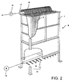
FIG. 2 is a diagram explaining a membrane separation device. -
FIG. 3 is a diagram explaining a membrane cartridge. -
FIG. 4A is a diagram showing a cross-sectional view of a main portion of the membrane cartridge in accordance with the present invention. -
FIG. 4B is a diagram showing a cross-sectional view of a main portion of a conventional membrane cartridge. -
FIG. 5A is a diagram explaining a method for producing a membrane cartridge in accordance with the present invention. -
FIGS. 5B and 5C are diagrams explaining the method of producing a membrane cartridge in accordance with other embodiments of the present invention. -
FIGS. 6A through 6C are diagrams explaining the method of producing a membrane cartridge in accordance with other embodiments of the present invention. - Hereinafter, embodiments of the membrane cartridge and the method for producing the membrane cartridge in accordance with the present invention are explained.
- As shown in
FIG. 1 , a wastewater treatment apparatus 1 employing a membrane bioreactor process is provided with apre-treatment equipment 2, a flow rate adjustingtank 3, a membrane separation tank 4 in which amembrane separation device 6 is immersed, and a treatedwater tank 5. - The
pre-treatment equipment 2 is provided with abar screen 2a and the like which removes foreign materials and the like mixed in raw water which becomes water to be treated. The flow rate adjustingtank 3 retains the raw water from which foreign materials have been removed by thebar screen 2a and the like. A flow rate adjusting mechanism such as a pump or valve, and the like, is provided such that the raw water is stably supplied to the membrane separation tank 4 from the flow rate adjustingtank 3 at a constant flow rate even if the raw water inflow fluctuates. - In the membrane separation tank 4 which is filled with activated sludge, organic matter contained in the raw water is decomposed by the biological treatment by the activated sludge, and permeated water which has been filtered via the
membrane separation device 6 is guided to the treatedwater tank 5 in which the permeated water is temporarily stored and then discharged. Excess of the activated sludge which has been multiplied in the membrane separation tank 4 is pulled out therefrom so as to maintain a constant concentration of the activated sludge. - As shown in
FIG. 2 , themembrane separation device 6 is provided with one hundred (100) plate-shaped membrane cartridges 8 disposed in amembrane case 7 having upper and lower open ends such that the membrane surfaces are arranged in respective longitudinal positions and separated from each other with a fixed distance of about 6 mm to 10 mm (8 mm in this embodiment), and with adiffuser device 12 disposed under themembrane case 7. - The
diffuser device 12 is provided with adiffusion pipe 13 having a plurality of diffusion holes, and is connected via adiffusion header 14 coupled to thediffusion pipe 13 to ablower 15 provided outside of the tank. - A
pump 18 as a pressure difference generating mechanism external to the tank is connected to themembrane cartridges 8 via aliquid collection pipe 17, whereby the water to be treated in the tank is sucked and filtered through a membrane of themembrane cartridges 8. - As shown in
FIG. 3 , in each of themembrane cartridges 8, afiltration membrane 10 is disposed on both of the front and rear faces of afiltration plate 9 made of a thermoplastic resin such as ABS resin having a height of 1000 mm and a width of 490 mm. A joiningportion 11 of thefiltration membrane 11 provided at the periphery thereof is bonded to thefiltration plate 9 by ultrasonic or thermal welding, or is adhered thereto using an adhesive. - The
filtration membrane 10 is an organic filtration membrane including asupport body 10a formed of a nonwoven fabric made of PET fiber, for example, and amicroporous membrane 10b having an average pore diameter of about 0.2 µm, which is formed by coating and impregnating thesupport body 10a with a porous resin. - A plurality of
grooves 9b having a depth of about 2 mm and a width of about 2 mm are formed on a surface of thefiltration plate 9 along a longitudinal direction, and ahorizontal groove 9c is formed at an upper end of thegrooves 9b so as to communicate with each of thegrooves 9b. The front and rear surfaces of thefiltration plate 9 have respectivehorizontal grooves 9c which communicate with each other via acommunication hole 9d which in turn communicates with anozzle 9a formed at an upper edge portion of thefiltration plate 9. - As shown in
FIG. 2 , thenozzle 9a is connected to theliquid collection pipe 17 via arespective tube 16, and thepump 18 is connected to theliquid collection pipe 17, such that the permeated water sucked by thepump 18 is transported to the treatedwater tank 5. - By operating the
diffuser device 12 in themembrane separation device 6 and thepump 18, a filtering operation is performed to obtain the permeated water by passing the water to be treated through thefiltration membrane 10. - A relaxation operation in which only the
diffuser device 12 is operated while thepump 18 is stopped is performed regularly, or when the suction pressure during the filtering operation becomes high, in order to prevent fouling of thefiltration membrane 10 while maintaining characteristics of the activated sludge in the tank. - In addition, a chemical solution cleaning process for cleaning the
filtration membrane 10 by injecting a chemical solution into eachmembrane cartridge 8 via theliquid collection pipe 17 is performed regularly, or when the suction pressure after the relaxation operation becomes high. - The
membrane cartridge 8 vibrates vigorously during the filtering operation due to an upward flow accompanying the air diffusion from below, whereby thefiltration membrane 10 does not follow the vibration of thefiltration plate 9 so as to repeatedly cling to and separate from thefiltration plate 9. During the relaxation operation in which thepump 18 is stopped, thefiltration membrane 10 of themembrane cartridge 8 widely trembles in such a state that thefiltration membrane 10 is slightly bulged from thefiltration plate 9 due to the upward flow accompanying the air diffusion from below. During the chemical cleaning, the filtration membrane is maintained in a continuously bulged state. For example, in such a chemical cleaning process, thefiltration membrane 10 bulges from the filtration plate at the joining portion with a rising angle about 50 degrees. - The
filtration membrane 10 receives a strong stress to the joining portion by changing its position from that clings to thefiltration plate 9 to that bulging from thefiltration plate 9, and the risk that the filtration membrane raptures or comes off at the joining portion due to fatigue increases when the joining portion is repeatedly subject to such a stress over time. - Accordingly, as shown in the left diagram in
FIG. 4A , themembrane cartridge 8 has afiltration plate 9 and afiltration membrane 10 disposed on the surface of thefiltration plate 9, and a joiningportion 11 of thefiltration membrane 10 provided at a periphery thereof is joined to thefiltration plate 9 such that at least an inner edge portion P1 of the joiningportion 11 has a downward inclination with respect to the surface P2 of thefiltration plate 9 inside of the inner edge portion P1 toward an outer peripheral edge P3 of thefiltration membrane 10. - As shown in the right diagram in
FIG. 4A , by providing at least the inner edge portion P1 within the joiningportion 11 with the downward inclination with respect to the filtration plate surface P2 inside of the inner edge portion P1 downwardly inclining toward the outer peripheral edge P3 of thefiltration membrane 10, a bulging angle of thefiltration membrane 10 with respect to the inner edge portion P1, i.e., a rising angle θ of the filtration membrane 10(A) indicated by a two-dot chain line with respect to the inner edge portion P1, becomes relatively small, compared with such an angle formed with respect to an inner edge portion parallel to or flush with the filtration plate surface P2 inside thereof, thereby reducing a bending stress affecting the joiningportion 11 of thefiltration membrane 10. It should be noted that the entire joiningportion 11 may be formed into a downward inclination in the width direction with respect to the filtration plate surface P2 toward the outer peripheral edge P3 of thefiltration membrane 10. - The right side diagram in
FIG. 4B shows a conventional structure in which the inner edge portion P1 of the joiningportion 11 is formed parallel to or flush with the filtration plate surface P2 inside thereof. As shown in the figure, in a case where the filtration membrane 10(B) indicated by a two-dot chain line bulges from the filtration plate surface adjacent to the joiningportion 11 at a rising angle 2θ, if the structure shown inFIG. 4A is employed, the bending stress would be reduced to that of the rising angle θ, whereby the fatigue durability can be increased. - It is preferable that the downward inclination is equal to or greater than 10 degrees and equal to or smaller than 50 degrees, and more preferably, the downward inclination is equal to or greater than 15 degrees and equal to or smaller than 35 degrees. By forming the downward inclination equal to or greater than 10 degrees and equal to or smaller than 50 degrees, bending of the
filtration membrane 10 at the joiningportion 11 can be effectively suppressed, and by forming the downward inclination equal to or greater than 15 degrees and equal to or smaller than 35 degrees, the bending of thefiltration membrane 10 at the joiningportion 11 can be further effectively suppressed. The width of the downwardly inclined area in the joiningportion 11 is preferably in a range between 1 mm and 10 mm. - The
filtration membrane 10 may be welded to thefiltration plate 9 by pressing a heating plate heated to a predetermined temperature or an ultrasonic horn onto thefiltration plate 9 with the periphery of thefiltration membrane 10 sandwiched therebetween. In addition to the heating plate and ultrasonic horn, a high-temperature gas such as heating steam can be jetted out from a tip of a heating member. An adhesive may also be used for bonding thefiltration membrane 10 to thefiltration plate 9. - In the latter case, an inclined portion can be formed in advance in an area of the
filtration plate 9 which correspond to the inner edge portion of the joining portion such that the inclined portion is downwardly inclined with respect to the surface of thefiltration plate 9 toward the outer edge of thefiltration membrane 10. - In the former case, the heating plate, the ultrasonic horn, or the heating member may have such a slope that at least the inner edge portion is provided with the downward inclination with respect to the surface of the filtration plate inside of the inner edge portion toward the outer peripheral edge of the filtration membrane.
- For example, as shown in
FIG. 5A , thefiltration membrane 10 can be welded to thefiltration plate 9 by pressing a heating plate orultrasonic horn 20 having a sloped tip portion having a predetermined inclination angle onto the surface of thefiltration plate 9 from above. - In addition, as shown in
FIG. 6A , a heating plate orultrasonic horn 20 having a tip portion having a V-shaped cross-section with a predetermined inclination angel can be used. As shown inFIG. 6B , a heating plate orultrasonic horn 20 having a partially sloped tip portion having a slope corresponding to the inner edge portion of the joiningportion 11 can also be used such that the remaining portion of the joiningportion 11 has a flat surface. As shown inFIG. 6C , a heating plate orultrasonic horn 20 may have a tip portion having a convex cross-section with an inclination angle within a predetermined range. -
FIG. 5A illustrates an example in which a downward inclination inclined with respect to the surface of thefiltration plate 9 inside of the inner edge portion of the joiningportion 11 toward the outer peripheral edge of thefiltration membrane 10 is formed in the inner edge portion by pressing the heating plate orultrasonic horn 20 onto thefiltration plate 9 having a flat surface. -
FIG. 5B illustrates an example in which a downward inclination inclined with respect to the surface of thefiltration plate 9 inside of the inner edge portion of the joiningportion 11 toward the outer peripheral edge of thefiltration membrane 10 is formed in the inner edge portion by pressing the heating plate orultrasonic horn 20 onto thefiltration plate 9 provided with a protrusion having a flat top surface in an area corresponding to the joiningportion 11. -
FIG. 5C illustrates an example in which a downward inclination inclined with respect to the surface of thefiltration plate 9 inside of the inner edge portion of the joiningportion 11 toward the outer peripheral edge of thefiltration membrane 10 is formed in the inner edge portion by pressing the heating plate orultrasonic horn 20 onto thefiltration plate 9 provided with a protrusion having an upward inclination toward the outer peripheral edge of thefiltration membrane 10 in an area corresponding to the joiningportion 11. - It is preferable that the surface of the
filtration plate 9 corresponding to the joiningportion 11 does not have a downward inclination before the joining process. Since the surface of thefiltration plate 9 corresponding to the joiningportion 11 does not have a downward inclination before the joining process and then is formed into a downward inclination through the joining process, even if the joining conditions fluctuate, for example, the temperature applied to thefiltration plate 9 from the heating plate orultrasonic horn 20 varies, an amount of thermal deformation or a time period during which the heating plate or ultrasonic horn is in contact with varies over the width of the joining portion in order to form such a downward inclination through the joining process, an area realizing a sufficient bonding strength between thefiltration plate 9 and thefiltration membrane 10 can be secured within the width of the joining portion. - For example, as shown in
FIG. 5A , when a flat surface of thefiltration plate 9 before the joining becomes a downward inclination after the joining, the maximum quantity of heat is applied to the outer edge of the joining width and the minimum quantity of heat is applied to the inner edge thereof, and thus it is more likely that the sufficient joining strength is realized in a certain area therebetween. - In addition, when the filtration membrane is joined to the filtration plate using a heating plate or ultrasonic horn, it is preferable that the temperature in the joining portion is equal to or higher than a softening point of the resin constituting the filtration plate and lower than a melting point of the unwoven fabric constituting the filtration membrane, such that the downward slope can be formed in the filtration plate while maintaining the strength of the filtration membrane.
- For example, when the filtration plate is made of ABS resin and the nonwoven fabric of the filtration membrane is made of PET resin, the preferable temperature is equal to or greater than 150°C and equal to or smaller than 250°C, and the output of the heating plate or ultrasonic horn can be adjusted such that the joining portion has the temperature between 150°C and 250°C.
- Each embodiment mentioned above is an example of the present invention, and the present invention is not limited by the description. The material, size, and thickness of the filtration plate and filtration membrane, the shape of the tip of the heating plate or ultrasonic horn, the joining temperature, and the like are not limited to specific examples, but a design of the specific structure of each part can be changed so long as the function and effect of the present invention can be achieved.
-
- 9: filtration plate
- 10: filtration membrane
- 11: joining portion
- P1: inner edge portion of the joining portion
- P2: surface of the filtration plate inside of the inner edge portion
- P3: outer peripheral edge of the filtration membrane
Claims (7)
- A membrane cartridge comprising a filtration plate made of a thermoplastic resin, a filtration membrane disposed on a surface of the filtration plate, and a joining portion of the filtration membrane provided at a periphery thereof and joined to the filtration plate,
wherein at least an inner edge portion of the joining portion has a downward inclination with respect to the surface of the filtration plate inside of the inner edge portion toward an outer peripheral edge of the filtration membrane. - The membrane cartridge of claim 1, wherein the downward inclination is equal to or greater than 10 degrees and equal to or smaller than 50 degrees.
- The membrane cartridge of claim 1, wherein the downward inclination is equal to or greater than 15 degrees and equal to or smaller than 35 degrees.
- A method for producing a membrane cartridge comprising a filtration plate made of a thermoplastic resin, a filtration membrane disposed on a surface of the filtration plate, and a joining portion of the filtration membrane provided at a periphery thereof and joined to the filtration plate, the method comprising:joining the filtration membrane by pressing a pressing tool onto the filtration plate with the periphery of the filtration membrane sandwiched therebetween, the pressing tool having such a slope that at least an inner edge portion of the joining portion is provided with a downward inclination with respect to the surface of the filtration plate inside of the inner edge portion toward an outer peripheral edge of the filtration membrane.
- The method of claim 4, wherein the surface of the filtration plate corresponding to the joining portion is not downwardly sloped before the joining.
- The method of claim 4 or 5, wherein the slope of the pressing tool is set such that the downward inclination is equal to or greater than 10 degrees and equal to or smaller than 50 degrees.
- The method of claim 4 or 5, wherein the slope of the pressing tool is set such that the downward inclination is equal to or greater than 15 degrees and equal to or smaller than 35 degrees.
Applications Claiming Priority (2)
| Application Number | Priority Date | Filing Date | Title |
|---|---|---|---|
| JP2013066087A JP6294592B2 (en) | 2013-03-27 | 2013-03-27 | Membrane cartridge manufacturing method |
| PCT/JP2014/058790 WO2014157489A1 (en) | 2013-03-27 | 2014-03-27 | Membrane cartridge, and membrane-cartridge production method |
Publications (3)
| Publication Number | Publication Date |
|---|---|
| EP2985070A1 true EP2985070A1 (en) | 2016-02-17 |
| EP2985070A4 EP2985070A4 (en) | 2016-11-23 |
| EP2985070B1 EP2985070B1 (en) | 2023-11-29 |
Family
ID=51624451
Family Applications (1)
| Application Number | Title | Priority Date | Filing Date |
|---|---|---|---|
| EP14775284.4A Active EP2985070B1 (en) | 2013-03-27 | 2014-03-27 | Membrane cartridge, and membrane-cartridge production method |
Country Status (6)
| Country | Link |
|---|---|
| US (1) | US10328394B2 (en) |
| EP (1) | EP2985070B1 (en) |
| JP (1) | JP6294592B2 (en) |
| CN (1) | CN104902985B (en) |
| ES (1) | ES2966854T3 (en) |
| WO (1) | WO2014157489A1 (en) |
Cited By (1)
| Publication number | Priority date | Publication date | Assignee | Title |
|---|---|---|---|---|
| EP3127598A4 (en) * | 2014-03-31 | 2017-11-15 | Kubota Corporation | Method for manufacturing flat membrane element and flat membrane element |
Families Citing this family (4)
| Publication number | Priority date | Publication date | Assignee | Title |
|---|---|---|---|---|
| JP6460856B2 (en) * | 2015-03-13 | 2019-01-30 | 株式会社クボタ | Membrane element manufacturing method |
| CN111093829B (en) * | 2017-03-22 | 2022-09-27 | 非链实验室 | Sample plate for buffer exchange and method of manufacture |
| CN109794170A (en) * | 2019-03-13 | 2019-05-24 | 殷伟卿 | A new type of submerged MBR flat plate separation membrane element, preparation method and repair method |
| JP7544064B2 (en) * | 2019-09-26 | 2024-09-03 | 東洋紡エムシー株式会社 | Submerged flat membrane element and its manufacturing method |
Family Cites Families (14)
| Publication number | Priority date | Publication date | Assignee | Title |
|---|---|---|---|---|
| JPH05168868A (en) * | 1991-12-18 | 1993-07-02 | Daicel Chem Ind Ltd | Semipermeable membrane module |
| US5651888A (en) * | 1992-12-16 | 1997-07-29 | Kubota Corporation | Filtration membrane cartridge |
| JPH06218240A (en) * | 1993-01-26 | 1994-08-09 | Kubota Corp | Membrane module manufacturing method |
| JP3576050B2 (en) * | 1999-10-26 | 2004-10-13 | 株式会社クボタ | Manufacturing method of immersion type membrane cartridge |
| JP4369153B2 (en) | 2002-05-16 | 2009-11-18 | 株式会社神鋼環境ソリューション | Membrane separation device and membrane separation method |
| CN1895755A (en) * | 2002-05-16 | 2007-01-17 | 株式会社神钢环境舒立净 | Membrane separation device and membrane separation method |
| JP5079984B2 (en) * | 2005-02-23 | 2012-11-21 | 株式会社Gsユアサ | Membrane element manufacturing method |
| JP2008049239A (en) * | 2006-08-23 | 2008-03-06 | Gs Yuasa Corporation:Kk | Membrane element |
| JP2008073680A (en) * | 2006-09-22 | 2008-04-03 | Membrane-Tec Co Ltd | Filtration cartridge |
| JP5473211B2 (en) * | 2007-11-28 | 2014-04-16 | 株式会社クボタ | Membrane cartridge and submerged membrane separator |
| US20110011787A1 (en) * | 2008-03-27 | 2011-01-20 | Hidetoshi Masutani | Membrane element and membrane module |
| US20110005994A1 (en) | 2008-03-27 | 2011-01-13 | Hidetoshi Masutani | Membrane element and membrane module |
| JP5603112B2 (en) * | 2010-03-17 | 2014-10-08 | 志摩環境事業協業組合 | Filtration treatment capacity adjustment method in membrane unit for submerged membrane separator using flat membrane element |
| DE102010062773A1 (en) * | 2010-12-09 | 2012-06-14 | Wyatt Technology Europe Gmbh | Flat duct seal |
-
2013
- 2013-03-27 JP JP2013066087A patent/JP6294592B2/en active Active
-
2014
- 2014-03-27 WO PCT/JP2014/058790 patent/WO2014157489A1/en not_active Ceased
- 2014-03-27 ES ES14775284T patent/ES2966854T3/en active Active
- 2014-03-27 EP EP14775284.4A patent/EP2985070B1/en active Active
- 2014-03-27 CN CN201480004064.7A patent/CN104902985B/en active Active
-
2015
- 2015-09-25 US US14/866,577 patent/US10328394B2/en active Active
Cited By (2)
| Publication number | Priority date | Publication date | Assignee | Title |
|---|---|---|---|---|
| EP3127598A4 (en) * | 2014-03-31 | 2017-11-15 | Kubota Corporation | Method for manufacturing flat membrane element and flat membrane element |
| US10335744B2 (en) | 2014-03-31 | 2019-07-02 | Kubota Corporation | Method of producing flat sheet membrane element and flat sheet membrane element |
Also Published As
| Publication number | Publication date |
|---|---|
| CN104902985B (en) | 2017-11-14 |
| EP2985070B1 (en) | 2023-11-29 |
| ES2966854T3 (en) | 2024-04-24 |
| WO2014157489A1 (en) | 2014-10-02 |
| JP2014188445A (en) | 2014-10-06 |
| EP2985070A4 (en) | 2016-11-23 |
| CN104902985A (en) | 2015-09-09 |
| US10328394B2 (en) | 2019-06-25 |
| US20160016123A1 (en) | 2016-01-21 |
| JP6294592B2 (en) | 2018-03-14 |
Similar Documents
| Publication | Publication Date | Title |
|---|---|---|
| US10328394B2 (en) | Membrane cartridge and membrane-cartridge production method | |
| JP2001212436A (en) | Immersion type membrane cartridge and method of manufacturing the same | |
| EP2666536B1 (en) | Membrane separation device | |
| CN102470323A (en) | Flat membrane element for filtration, flat membrane type separation membrane module, and filtration device | |
| US20110011787A1 (en) | Membrane element and membrane module | |
| US20110005994A1 (en) | Membrane element and membrane module | |
| KR20150036221A (en) | Element unit, separation membrane module, and method for connecting/disconnecting separation membrane element | |
| US10335744B2 (en) | Method of producing flat sheet membrane element and flat sheet membrane element | |
| EP3070059B1 (en) | Air diffusion pipe and method for washing air diffusion pipe | |
| JP6215551B2 (en) | Membrane cartridge | |
| JPWO2008117783A1 (en) | Membrane element and membrane separator | |
| JP2008049239A (en) | Membrane element | |
| US8465644B2 (en) | Membrane element in immersion type membrane separation apparatus | |
| JP2010094589A (en) | Hollow fiber membrane element and hollow fiber membrane module using the same | |
| CN114514064B (en) | Impregnated flat membrane element and method for manufacturing same | |
| JP5889694B2 (en) | Immersion flat membrane element and membrane unit using immersion flat membrane element | |
| JP4969079B2 (en) | Membrane periphery fixing structure of submerged membrane cartridge | |
| JP2010042375A (en) | Membrane element, its manufacturing method and resin plate | |
| JP2009233571A (en) | Element array fixing implement and membrane separation apparatus | |
| JP2016000515A (en) | Liquid ejecting head manufacturing method, liquid ejecting head, and liquid ejecting apparatus | |
| JP2006116497A (en) | Filter device | |
| JP2013202514A (en) | Immersion type flat film element | |
| KR20130143193A (en) | Membrane module equipped with all-in-one air diffuser and ultrasonic generator | |
| JP2014057965A (en) | Plate membrane element and immersing type membrane separator using the same | |
| JP2009208032A (en) | Membrane element |
Legal Events
| Date | Code | Title | Description |
|---|---|---|---|
| PUAI | Public reference made under article 153(3) epc to a published international application that has entered the european phase |
Free format text: ORIGINAL CODE: 0009012 |
|
| 17P | Request for examination filed |
Effective date: 20150924 |
|
| AK | Designated contracting states |
Kind code of ref document: A1 Designated state(s): AL AT BE BG CH CY CZ DE DK EE ES FI FR GB GR HR HU IE IS IT LI LT LU LV MC MK MT NL NO PL PT RO RS SE SI SK SM TR |
|
| AX | Request for extension of the european patent |
Extension state: BA ME |
|
| DAX | Request for extension of the european patent (deleted) | ||
| A4 | Supplementary search report drawn up and despatched |
Effective date: 20161024 |
|
| RIC1 | Information provided on ipc code assigned before grant |
Ipc: B01D 65/00 20060101ALI20161018BHEP Ipc: B01D 61/18 20060101ALI20161018BHEP Ipc: B01D 63/00 20060101AFI20161018BHEP Ipc: B01D 63/08 20060101ALI20161018BHEP |
|
| STAA | Information on the status of an ep patent application or granted ep patent |
Free format text: STATUS: EXAMINATION IS IN PROGRESS |
|
| 17Q | First examination report despatched |
Effective date: 20180323 |
|
| GRAP | Despatch of communication of intention to grant a patent |
Free format text: ORIGINAL CODE: EPIDOSNIGR1 |
|
| STAA | Information on the status of an ep patent application or granted ep patent |
Free format text: STATUS: GRANT OF PATENT IS INTENDED |
|
| INTG | Intention to grant announced |
Effective date: 20230404 |
|
| GRAJ | Information related to disapproval of communication of intention to grant by the applicant or resumption of examination proceedings by the epo deleted |
Free format text: ORIGINAL CODE: EPIDOSDIGR1 |
|
| STAA | Information on the status of an ep patent application or granted ep patent |
Free format text: STATUS: EXAMINATION IS IN PROGRESS |
|
| GRAP | Despatch of communication of intention to grant a patent |
Free format text: ORIGINAL CODE: EPIDOSNIGR1 |
|
| STAA | Information on the status of an ep patent application or granted ep patent |
Free format text: STATUS: GRANT OF PATENT IS INTENDED |
|
| INTC | Intention to grant announced (deleted) | ||
| INTG | Intention to grant announced |
Effective date: 20230621 |
|
| GRAS | Grant fee paid |
Free format text: ORIGINAL CODE: EPIDOSNIGR3 |
|
| GRAA | (expected) grant |
Free format text: ORIGINAL CODE: 0009210 |
|
| STAA | Information on the status of an ep patent application or granted ep patent |
Free format text: STATUS: THE PATENT HAS BEEN GRANTED |
|
| AK | Designated contracting states |
Kind code of ref document: B1 Designated state(s): AL AT BE BG CH CY CZ DE DK EE ES FI FR GB GR HR HU IE IS IT LI LT LU LV MC MK MT NL NO PL PT RO RS SE SI SK SM TR |
|
| REG | Reference to a national code |
Ref country code: GB Ref legal event code: FG4D |
|
| REG | Reference to a national code |
Ref country code: CH Ref legal event code: EP |
|
| REG | Reference to a national code |
Ref country code: DE Ref legal event code: R096 Ref document number: 602014088996 Country of ref document: DE |
|
| REG | Reference to a national code |
Ref country code: IE Ref legal event code: FG4D |
|
| REG | Reference to a national code |
Ref country code: LT Ref legal event code: MG9D |
|
| REG | Reference to a national code |
Ref country code: NL Ref legal event code: MP Effective date: 20231129 |
|
| PG25 | Lapsed in a contracting state [announced via postgrant information from national office to epo] |
Ref country code: GR Free format text: LAPSE BECAUSE OF FAILURE TO SUBMIT A TRANSLATION OF THE DESCRIPTION OR TO PAY THE FEE WITHIN THE PRESCRIBED TIME-LIMIT Effective date: 20240301 |
|
| PG25 | Lapsed in a contracting state [announced via postgrant information from national office to epo] |
Ref country code: IS Free format text: LAPSE BECAUSE OF FAILURE TO SUBMIT A TRANSLATION OF THE DESCRIPTION OR TO PAY THE FEE WITHIN THE PRESCRIBED TIME-LIMIT Effective date: 20240329 |
|
| PG25 | Lapsed in a contracting state [announced via postgrant information from national office to epo] |
Ref country code: LT Free format text: LAPSE BECAUSE OF FAILURE TO SUBMIT A TRANSLATION OF THE DESCRIPTION OR TO PAY THE FEE WITHIN THE PRESCRIBED TIME-LIMIT Effective date: 20231129 |
|
| REG | Reference to a national code |
Ref country code: ES Ref legal event code: FG2A Ref document number: 2966854 Country of ref document: ES Kind code of ref document: T3 Effective date: 20240424 |
|
| PG25 | Lapsed in a contracting state [announced via postgrant information from national office to epo] |
Ref country code: LT Free format text: LAPSE BECAUSE OF FAILURE TO SUBMIT A TRANSLATION OF THE DESCRIPTION OR TO PAY THE FEE WITHIN THE PRESCRIBED TIME-LIMIT Effective date: 20231129 Ref country code: IS Free format text: LAPSE BECAUSE OF FAILURE TO SUBMIT A TRANSLATION OF THE DESCRIPTION OR TO PAY THE FEE WITHIN THE PRESCRIBED TIME-LIMIT Effective date: 20240329 Ref country code: GR Free format text: LAPSE BECAUSE OF FAILURE TO SUBMIT A TRANSLATION OF THE DESCRIPTION OR TO PAY THE FEE WITHIN THE PRESCRIBED TIME-LIMIT Effective date: 20240301 Ref country code: BG Free format text: LAPSE BECAUSE OF FAILURE TO SUBMIT A TRANSLATION OF THE DESCRIPTION OR TO PAY THE FEE WITHIN THE PRESCRIBED TIME-LIMIT Effective date: 20240229 |
|
| REG | Reference to a national code |
Ref country code: AT Ref legal event code: MK05 Ref document number: 1635549 Country of ref document: AT Kind code of ref document: T Effective date: 20231129 |
|
| PG25 | Lapsed in a contracting state [announced via postgrant information from national office to epo] |
Ref country code: NL Free format text: LAPSE BECAUSE OF FAILURE TO SUBMIT A TRANSLATION OF THE DESCRIPTION OR TO PAY THE FEE WITHIN THE PRESCRIBED TIME-LIMIT Effective date: 20231129 |
|
| PG25 | Lapsed in a contracting state [announced via postgrant information from national office to epo] |
Ref country code: SE Free format text: LAPSE BECAUSE OF FAILURE TO SUBMIT A TRANSLATION OF THE DESCRIPTION OR TO PAY THE FEE WITHIN THE PRESCRIBED TIME-LIMIT Effective date: 20231129 Ref country code: RS Free format text: LAPSE BECAUSE OF FAILURE TO SUBMIT A TRANSLATION OF THE DESCRIPTION OR TO PAY THE FEE WITHIN THE PRESCRIBED TIME-LIMIT Effective date: 20231129 Ref country code: PL Free format text: LAPSE BECAUSE OF FAILURE TO SUBMIT A TRANSLATION OF THE DESCRIPTION OR TO PAY THE FEE WITHIN THE PRESCRIBED TIME-LIMIT Effective date: 20231129 Ref country code: NO Free format text: LAPSE BECAUSE OF FAILURE TO SUBMIT A TRANSLATION OF THE DESCRIPTION OR TO PAY THE FEE WITHIN THE PRESCRIBED TIME-LIMIT Effective date: 20240229 Ref country code: NL Free format text: LAPSE BECAUSE OF FAILURE TO SUBMIT A TRANSLATION OF THE DESCRIPTION OR TO PAY THE FEE WITHIN THE PRESCRIBED TIME-LIMIT Effective date: 20231129 Ref country code: LV Free format text: LAPSE BECAUSE OF FAILURE TO SUBMIT A TRANSLATION OF THE DESCRIPTION OR TO PAY THE FEE WITHIN THE PRESCRIBED TIME-LIMIT Effective date: 20231129 Ref country code: HR Free format text: LAPSE BECAUSE OF FAILURE TO SUBMIT A TRANSLATION OF THE DESCRIPTION OR TO PAY THE FEE WITHIN THE PRESCRIBED TIME-LIMIT Effective date: 20231129 |
|
| PG25 | Lapsed in a contracting state [announced via postgrant information from national office to epo] |
Ref country code: DK Free format text: LAPSE BECAUSE OF FAILURE TO SUBMIT A TRANSLATION OF THE DESCRIPTION OR TO PAY THE FEE WITHIN THE PRESCRIBED TIME-LIMIT Effective date: 20231129 |
|
| PG25 | Lapsed in a contracting state [announced via postgrant information from national office to epo] |
Ref country code: CZ Free format text: LAPSE BECAUSE OF FAILURE TO SUBMIT A TRANSLATION OF THE DESCRIPTION OR TO PAY THE FEE WITHIN THE PRESCRIBED TIME-LIMIT Effective date: 20231129 Ref country code: AT Free format text: LAPSE BECAUSE OF FAILURE TO SUBMIT A TRANSLATION OF THE DESCRIPTION OR TO PAY THE FEE WITHIN THE PRESCRIBED TIME-LIMIT Effective date: 20231129 |
|
| PG25 | Lapsed in a contracting state [announced via postgrant information from national office to epo] |
Ref country code: SK Free format text: LAPSE BECAUSE OF FAILURE TO SUBMIT A TRANSLATION OF THE DESCRIPTION OR TO PAY THE FEE WITHIN THE PRESCRIBED TIME-LIMIT Effective date: 20231129 |
|
| PG25 | Lapsed in a contracting state [announced via postgrant information from national office to epo] |
Ref country code: SM Free format text: LAPSE BECAUSE OF FAILURE TO SUBMIT A TRANSLATION OF THE DESCRIPTION OR TO PAY THE FEE WITHIN THE PRESCRIBED TIME-LIMIT Effective date: 20231129 Ref country code: SK Free format text: LAPSE BECAUSE OF FAILURE TO SUBMIT A TRANSLATION OF THE DESCRIPTION OR TO PAY THE FEE WITHIN THE PRESCRIBED TIME-LIMIT Effective date: 20231129 Ref country code: RO Free format text: LAPSE BECAUSE OF FAILURE TO SUBMIT A TRANSLATION OF THE DESCRIPTION OR TO PAY THE FEE WITHIN THE PRESCRIBED TIME-LIMIT Effective date: 20231129 Ref country code: EE Free format text: LAPSE BECAUSE OF FAILURE TO SUBMIT A TRANSLATION OF THE DESCRIPTION OR TO PAY THE FEE WITHIN THE PRESCRIBED TIME-LIMIT Effective date: 20231129 Ref country code: DK Free format text: LAPSE BECAUSE OF FAILURE TO SUBMIT A TRANSLATION OF THE DESCRIPTION OR TO PAY THE FEE WITHIN THE PRESCRIBED TIME-LIMIT Effective date: 20231129 Ref country code: CZ Free format text: LAPSE BECAUSE OF FAILURE TO SUBMIT A TRANSLATION OF THE DESCRIPTION OR TO PAY THE FEE WITHIN THE PRESCRIBED TIME-LIMIT Effective date: 20231129 Ref country code: AT Free format text: LAPSE BECAUSE OF FAILURE TO SUBMIT A TRANSLATION OF THE DESCRIPTION OR TO PAY THE FEE WITHIN THE PRESCRIBED TIME-LIMIT Effective date: 20231129 |
|
| PG25 | Lapsed in a contracting state [announced via postgrant information from national office to epo] |
Ref country code: PT Free format text: LAPSE BECAUSE OF FAILURE TO SUBMIT A TRANSLATION OF THE DESCRIPTION OR TO PAY THE FEE WITHIN THE PRESCRIBED TIME-LIMIT Effective date: 20240401 |
|
| PG25 | Lapsed in a contracting state [announced via postgrant information from national office to epo] |
Ref country code: PT Free format text: LAPSE BECAUSE OF FAILURE TO SUBMIT A TRANSLATION OF THE DESCRIPTION OR TO PAY THE FEE WITHIN THE PRESCRIBED TIME-LIMIT Effective date: 20240401 |
|
| REG | Reference to a national code |
Ref country code: DE Ref legal event code: R097 Ref document number: 602014088996 Country of ref document: DE |
|
| PLBE | No opposition filed within time limit |
Free format text: ORIGINAL CODE: 0009261 |
|
| STAA | Information on the status of an ep patent application or granted ep patent |
Free format text: STATUS: NO OPPOSITION FILED WITHIN TIME LIMIT |
|
| PG25 | Lapsed in a contracting state [announced via postgrant information from national office to epo] |
Ref country code: SI Free format text: LAPSE BECAUSE OF FAILURE TO SUBMIT A TRANSLATION OF THE DESCRIPTION OR TO PAY THE FEE WITHIN THE PRESCRIBED TIME-LIMIT Effective date: 20231129 |
|
| PG25 | Lapsed in a contracting state [announced via postgrant information from national office to epo] |
Ref country code: SI Free format text: LAPSE BECAUSE OF FAILURE TO SUBMIT A TRANSLATION OF THE DESCRIPTION OR TO PAY THE FEE WITHIN THE PRESCRIBED TIME-LIMIT Effective date: 20231129 |
|
| REG | Reference to a national code |
Ref country code: CH Ref legal event code: PL |
|
| 26N | No opposition filed |
Effective date: 20240830 |
|
| PG25 | Lapsed in a contracting state [announced via postgrant information from national office to epo] |
Ref country code: LU Free format text: LAPSE BECAUSE OF NON-PAYMENT OF DUE FEES Effective date: 20240327 |
|
| PG25 | Lapsed in a contracting state [announced via postgrant information from national office to epo] |
Ref country code: MC Free format text: LAPSE BECAUSE OF FAILURE TO SUBMIT A TRANSLATION OF THE DESCRIPTION OR TO PAY THE FEE WITHIN THE PRESCRIBED TIME-LIMIT Effective date: 20231129 |
|
| PG25 | Lapsed in a contracting state [announced via postgrant information from national office to epo] |
Ref country code: MC Free format text: LAPSE BECAUSE OF FAILURE TO SUBMIT A TRANSLATION OF THE DESCRIPTION OR TO PAY THE FEE WITHIN THE PRESCRIBED TIME-LIMIT Effective date: 20231129 Ref country code: LU Free format text: LAPSE BECAUSE OF NON-PAYMENT OF DUE FEES Effective date: 20240327 |
|
| REG | Reference to a national code |
Ref country code: BE Ref legal event code: MM Effective date: 20240331 |
|
| PG25 | Lapsed in a contracting state [announced via postgrant information from national office to epo] |
Ref country code: BE Free format text: LAPSE BECAUSE OF NON-PAYMENT OF DUE FEES Effective date: 20240331 |
|
| PG25 | Lapsed in a contracting state [announced via postgrant information from national office to epo] |
Ref country code: IE Free format text: LAPSE BECAUSE OF NON-PAYMENT OF DUE FEES Effective date: 20240327 |
|
| PG25 | Lapsed in a contracting state [announced via postgrant information from national office to epo] |
Ref country code: IE Free format text: LAPSE BECAUSE OF NON-PAYMENT OF DUE FEES Effective date: 20240327 Ref country code: BE Free format text: LAPSE BECAUSE OF NON-PAYMENT OF DUE FEES Effective date: 20240331 Ref country code: CH Free format text: LAPSE BECAUSE OF NON-PAYMENT OF DUE FEES Effective date: 20240331 |
|
| PGFP | Annual fee paid to national office [announced via postgrant information from national office to epo] |
Ref country code: ES Payment date: 20250403 Year of fee payment: 12 |
|
| PG25 | Lapsed in a contracting state [announced via postgrant information from national office to epo] |
Ref country code: CY Free format text: LAPSE BECAUSE OF FAILURE TO SUBMIT A TRANSLATION OF THE DESCRIPTION OR TO PAY THE FEE WITHIN THE PRESCRIBED TIME-LIMIT; INVALID AB INITIO Effective date: 20140327 |
|
| PG25 | Lapsed in a contracting state [announced via postgrant information from national office to epo] |
Ref country code: HU Free format text: LAPSE BECAUSE OF FAILURE TO SUBMIT A TRANSLATION OF THE DESCRIPTION OR TO PAY THE FEE WITHIN THE PRESCRIBED TIME-LIMIT; INVALID AB INITIO Effective date: 20140327 |
|
| PG25 | Lapsed in a contracting state [announced via postgrant information from national office to epo] |
Ref country code: FI Free format text: LAPSE BECAUSE OF FAILURE TO SUBMIT A TRANSLATION OF THE DESCRIPTION OR TO PAY THE FEE WITHIN THE PRESCRIBED TIME-LIMIT Effective date: 20231129 |
|
| PG25 | Lapsed in a contracting state [announced via postgrant information from national office to epo] |
Ref country code: TR Free format text: LAPSE BECAUSE OF FAILURE TO SUBMIT A TRANSLATION OF THE DESCRIPTION OR TO PAY THE FEE WITHIN THE PRESCRIBED TIME-LIMIT Effective date: 20231129 |
|
| PGFP | Annual fee paid to national office [announced via postgrant information from national office to epo] |
Ref country code: GB Payment date: 20260209 Year of fee payment: 13 |
|
| PGFP | Annual fee paid to national office [announced via postgrant information from national office to epo] |
Ref country code: DE Payment date: 20260128 Year of fee payment: 13 |
|
| PGFP | Annual fee paid to national office [announced via postgrant information from national office to epo] |
Ref country code: IT Payment date: 20260220 Year of fee payment: 13 |
|
| PGFP | Annual fee paid to national office [announced via postgrant information from national office to epo] |
Ref country code: FR Payment date: 20260209 Year of fee payment: 13 |