EP2984988A2 - Device and method for detecting a hose line laid in the receiving element of a tensioning unit for tensioning a hose line - Google Patents
Device and method for detecting a hose line laid in the receiving element of a tensioning unit for tensioning a hose line Download PDFInfo
- Publication number
- EP2984988A2 EP2984988A2 EP15183364.7A EP15183364A EP2984988A2 EP 2984988 A2 EP2984988 A2 EP 2984988A2 EP 15183364 A EP15183364 A EP 15183364A EP 2984988 A2 EP2984988 A2 EP 2984988A2
- Authority
- EP
- European Patent Office
- Prior art keywords
- hose
- receiving elements
- motor current
- unit
- clamping
- Prior art date
- Legal status (The legal status is an assumption and is not a legal conclusion. Google has not performed a legal analysis and makes no representation as to the accuracy of the status listed.)
- Granted
Links
- 238000000034 method Methods 0.000 title claims abstract description 21
- 210000004369 blood Anatomy 0.000 claims abstract description 79
- 239000008280 blood Substances 0.000 claims abstract description 79
- 238000005259 measurement Methods 0.000 claims abstract description 46
- 238000012544 monitoring process Methods 0.000 claims abstract description 25
- 230000007246 mechanism Effects 0.000 claims abstract description 24
- 230000017531 blood circulation Effects 0.000 claims abstract description 12
- 238000011156 evaluation Methods 0.000 claims description 36
- 239000000470 constituent Substances 0.000 claims description 12
- 230000007704 transition Effects 0.000 claims description 7
- 230000008859 change Effects 0.000 claims description 3
- 230000008878 coupling Effects 0.000 claims description 3
- 238000010168 coupling process Methods 0.000 claims description 3
- 238000005859 coupling reaction Methods 0.000 claims description 3
- 230000005670 electromagnetic radiation Effects 0.000 claims description 3
- 230000005855 radiation Effects 0.000 claims description 2
- 230000002596 correlated effect Effects 0.000 claims 3
- 238000012937 correction Methods 0.000 claims 2
- 239000012503 blood component Substances 0.000 abstract description 13
- 239000000306 component Substances 0.000 abstract description 9
- 239000000463 material Substances 0.000 description 13
- 238000013461 design Methods 0.000 description 6
- 238000001514 detection method Methods 0.000 description 6
- 239000000385 dialysis solution Substances 0.000 description 6
- 230000006835 compression Effects 0.000 description 4
- 238000007906 compression Methods 0.000 description 4
- 238000003825 pressing Methods 0.000 description 4
- 230000008569 process Effects 0.000 description 4
- 230000008901 benefit Effects 0.000 description 3
- 239000007788 liquid Substances 0.000 description 3
- 102000001554 Hemoglobins Human genes 0.000 description 2
- 108010054147 Hemoglobins Proteins 0.000 description 2
- 238000000502 dialysis Methods 0.000 description 2
- 210000003743 erythrocyte Anatomy 0.000 description 2
- 238000005534 hematocrit Methods 0.000 description 2
- 230000000630 rising effect Effects 0.000 description 2
- 238000012360 testing method Methods 0.000 description 2
- XLYOFNOQVPJJNP-UHFFFAOYSA-N water Substances O XLYOFNOQVPJJNP-UHFFFAOYSA-N 0.000 description 2
- 230000009286 beneficial effect Effects 0.000 description 1
- 230000015572 biosynthetic process Effects 0.000 description 1
- 230000000295 complement effect Effects 0.000 description 1
- 230000007423 decrease Effects 0.000 description 1
- 230000008030 elimination Effects 0.000 description 1
- 238000003379 elimination reaction Methods 0.000 description 1
- 238000002474 experimental method Methods 0.000 description 1
- 238000001125 extrusion Methods 0.000 description 1
- 230000010354 integration Effects 0.000 description 1
- 238000004519 manufacturing process Methods 0.000 description 1
- 239000012528 membrane Substances 0.000 description 1
- 230000004044 response Effects 0.000 description 1
- 238000004904 shortening Methods 0.000 description 1
- 238000012549 training Methods 0.000 description 1
- 230000000007 visual effect Effects 0.000 description 1
Images


Classifications
-
- G—PHYSICS
- G01—MEASURING; TESTING
- G01N—INVESTIGATING OR ANALYSING MATERIALS BY DETERMINING THEIR CHEMICAL OR PHYSICAL PROPERTIES
- G01N33/00—Investigating or analysing materials by specific methods not covered by groups G01N1/00 - G01N31/00
- G01N33/48—Biological material, e.g. blood, urine; Haemocytometers
- G01N33/483—Physical analysis of biological material
- G01N33/487—Physical analysis of biological material of liquid biological material
- G01N33/49—Blood
-
- A—HUMAN NECESSITIES
- A61—MEDICAL OR VETERINARY SCIENCE; HYGIENE
- A61B—DIAGNOSIS; SURGERY; IDENTIFICATION
- A61B5/00—Measuring for diagnostic purposes; Identification of persons
- A61B5/145—Measuring characteristics of blood in vivo, e.g. gas concentration, pH value; Measuring characteristics of body fluids or tissues, e.g. interstitial fluid, cerebral tissue
- A61B5/1455—Measuring characteristics of blood in vivo, e.g. gas concentration, pH value; Measuring characteristics of body fluids or tissues, e.g. interstitial fluid, cerebral tissue using optical sensors, e.g. spectral photometrical oximeters
- A61B5/14551—Measuring characteristics of blood in vivo, e.g. gas concentration, pH value; Measuring characteristics of body fluids or tissues, e.g. interstitial fluid, cerebral tissue using optical sensors, e.g. spectral photometrical oximeters for measuring blood gases
- A61B5/14557—Measuring characteristics of blood in vivo, e.g. gas concentration, pH value; Measuring characteristics of body fluids or tissues, e.g. interstitial fluid, cerebral tissue using optical sensors, e.g. spectral photometrical oximeters for measuring blood gases specially adapted to extracorporeal circuits
-
- A—HUMAN NECESSITIES
- A61—MEDICAL OR VETERINARY SCIENCE; HYGIENE
- A61M—DEVICES FOR INTRODUCING MEDIA INTO, OR ONTO, THE BODY; DEVICES FOR TRANSDUCING BODY MEDIA OR FOR TAKING MEDIA FROM THE BODY; DEVICES FOR PRODUCING OR ENDING SLEEP OR STUPOR
- A61M1/00—Suction or pumping devices for medical purposes; Devices for carrying-off, for treatment of, or for carrying-over, body-liquids; Drainage systems
- A61M1/36—Other treatment of blood in a by-pass of the natural circulatory system, e.g. temperature adaptation, irradiation ; Extra-corporeal blood circuits
- A61M1/3621—Extra-corporeal blood circuits
- A61M1/367—Circuit parts not covered by the preceding subgroups of group A61M1/3621
-
- G—PHYSICS
- G01—MEASURING; TESTING
- G01N—INVESTIGATING OR ANALYSING MATERIALS BY DETERMINING THEIR CHEMICAL OR PHYSICAL PROPERTIES
- G01N21/00—Investigating or analysing materials by the use of optical means, i.e. using sub-millimetre waves, infrared, visible or ultraviolet light
- G01N21/01—Arrangements or apparatus for facilitating the optical investigation
- G01N21/03—Cuvette constructions
- G01N21/05—Flow-through cuvettes
-
- G—PHYSICS
- G01—MEASURING; TESTING
- G01N—INVESTIGATING OR ANALYSING MATERIALS BY DETERMINING THEIR CHEMICAL OR PHYSICAL PROPERTIES
- G01N21/00—Investigating or analysing materials by the use of optical means, i.e. using sub-millimetre waves, infrared, visible or ultraviolet light
- G01N21/17—Systems in which incident light is modified in accordance with the properties of the material investigated
- G01N21/25—Colour; Spectral properties, i.e. comparison of effect of material on the light at two or more different wavelengths or wavelength bands
- G01N21/31—Investigating relative effect of material at wavelengths characteristic of specific elements or molecules, e.g. atomic absorption spectrometry
-
- A—HUMAN NECESSITIES
- A61—MEDICAL OR VETERINARY SCIENCE; HYGIENE
- A61M—DEVICES FOR INTRODUCING MEDIA INTO, OR ONTO, THE BODY; DEVICES FOR TRANSDUCING BODY MEDIA OR FOR TAKING MEDIA FROM THE BODY; DEVICES FOR PRODUCING OR ENDING SLEEP OR STUPOR
- A61M2205/00—General characteristics of the apparatus
- A61M2205/14—Detection of the presence or absence of a tube, a connector or a container in an apparatus
-
- A—HUMAN NECESSITIES
- A61—MEDICAL OR VETERINARY SCIENCE; HYGIENE
- A61M—DEVICES FOR INTRODUCING MEDIA INTO, OR ONTO, THE BODY; DEVICES FOR TRANSDUCING BODY MEDIA OR FOR TAKING MEDIA FROM THE BODY; DEVICES FOR PRODUCING OR ENDING SLEEP OR STUPOR
- A61M2205/00—General characteristics of the apparatus
- A61M2205/33—Controlling, regulating or measuring
- A61M2205/3306—Optical measuring means
-
- A—HUMAN NECESSITIES
- A61—MEDICAL OR VETERINARY SCIENCE; HYGIENE
- A61M—DEVICES FOR INTRODUCING MEDIA INTO, OR ONTO, THE BODY; DEVICES FOR TRANSDUCING BODY MEDIA OR FOR TAKING MEDIA FROM THE BODY; DEVICES FOR PRODUCING OR ENDING SLEEP OR STUPOR
- A61M2230/00—Measuring parameters of the user
- A61M2230/20—Blood composition characteristics
-
- G—PHYSICS
- G01—MEASURING; TESTING
- G01N—INVESTIGATING OR ANALYSING MATERIALS BY DETERMINING THEIR CHEMICAL OR PHYSICAL PROPERTIES
- G01N21/00—Investigating or analysing materials by the use of optical means, i.e. using sub-millimetre waves, infrared, visible or ultraviolet light
- G01N21/01—Arrangements or apparatus for facilitating the optical investigation
- G01N21/03—Cuvette constructions
- G01N2021/0378—Shapes
-
- G—PHYSICS
- G01—MEASURING; TESTING
- G01N—INVESTIGATING OR ANALYSING MATERIALS BY DETERMINING THEIR CHEMICAL OR PHYSICAL PROPERTIES
- G01N21/00—Investigating or analysing materials by the use of optical means, i.e. using sub-millimetre waves, infrared, visible or ultraviolet light
- G01N21/17—Systems in which incident light is modified in accordance with the properties of the material investigated
- G01N21/25—Colour; Spectral properties, i.e. comparison of effect of material on the light at two or more different wavelengths or wavelength bands
- G01N21/31—Investigating relative effect of material at wavelengths characteristic of specific elements or molecules, e.g. atomic absorption spectrometry
- G01N21/314—Investigating relative effect of material at wavelengths characteristic of specific elements or molecules, e.g. atomic absorption spectrometry with comparison of measurements at specific and non-specific wavelengths
- G01N2021/3144—Investigating relative effect of material at wavelengths characteristic of specific elements or molecules, e.g. atomic absorption spectrometry with comparison of measurements at specific and non-specific wavelengths for oxymetry
Definitions
- the invention relates to a device for clamping a tubing with a clamping unit, in particular a device for determining the concentration of a component of blood in a tubing, in particular a tubing of an extracorporeal blood circulation of an extracorporeal blood treatment device. Moreover, the invention relates to a method for detecting a tubing, in particular a tubing of an extracorporeal blood circulation of an extracorporeal blood treatment device, in a clamping unit, in particular a device for determining the concentration of a blood component in a tubing.
- the WO 2008/00433 A1 describes a device for determining the concentration of certain blood constituents in a blood-filled, substantially transparent tubing of an extracorporeal blood circulation.
- the known device allows the determination of the hemoglobin concentration and the proportion of red blood cells (erythrocytes) in the total volume of the blood.
- the tubing is clamped between two parallel, flat contact surfaces, so that the tubing deforms on the opposite sides.
- a light emitter light of a certain wavelength is coupled through the transparent tubing into the blood, while with a light detector the scattered or transmitted light is measured.
- the hematocrit is then determined from the ratio of the intensity of the light entering the blood and exiting the blood.
- a device for the determination of blood components which has a clamping unit for clamping the tubing and a measuring unit.
- the clamping unit is designed such that the clamped hose line has a square cross-section.
- the measuring unit has several light emitters and light detectors, which are arranged around the circumference of the hose line. The light emitters and light detectors are arranged such that the light emitters are in a different plane than the light detectors, so that light emitters and light detectors are not opposed to each other.
- the tubing is deformed in the clamping unit. Make sure that the hose line does not jam in the clamping unit.
- the invention has for its object to provide a device for clamping a tubing, which allows detection of a inserted into the receiving elements of a clamping unit of the device for clamping the tubing tubing, in particular to provide a device for determining the concentration of blood parameters in a tubing, which allows an automated measurement procedure with high measurement accuracy and the detection of a tube inserted into the receiving elements of the clamping unit of the device for determining the concentration of blood parameters.
- Another object of the invention is a method for detecting a hose in a clamping unit of a device for clamping a Specify tubing in particular a device for determining the concentration of a blood component.
- the inventive device for determining the concentration of a component of blood in a tubing, in particular the tubing of an extracorporeal blood circulation characterized in that the clamping unit has an actuating mechanism which is designed such that upon application of a clamping force, a first and second receiving element a first position releasing the hose line are movable relative to one another in a second position clamping the hose line, the drive of the actuating mechanism being effected with an electric motor.
- the electromotive drive allows the setting of a certain feed rate at which the receiving elements are moved. This makes it possible to press the hose together with an optimum feed rate, so that the hose line has the opportunity to center exactly between the receiving elements. As a result, jamming of the tubing as a result of too fast and not uniform movement of the clamping elements is avoided.
- the device according to the invention for determining the concentration of blood components is characterized by a monitoring unit which is designed such that the tube inserted into the receiving elements can be seen.
- a monitoring unit which is designed such that the tube inserted into the receiving elements can be seen.
- the motor current of the electric motor for driving the actuating mechanism of the clamping unit is measured for detecting the hose in the clamping unit, wherein on the basis of the change in the measured motor current, the inserted into the receiving elements of the clamping unit hose is detected.
- any variable correlating with the motor current for example the motor power
- the evaluation of the motor current for the detection of the hose can be done in a computing and evaluation unit, without further mechanical components are required.
- the computing and evaluation unit of the monitoring unit can be part of the computing and evaluation unit of the device for determining the concentration of the blood component. Both arithmetic and evaluation units can also be part of the central control unit or arithmetic and evaluation unit of an extracorporeal blood treatment device.
- the motor current has a characteristic course, which depends on whether a hose is clamped or not.
- a significant increase in the motor current shows much earlier, when the hose is inserted into the receiving elements.
- the increase of the motor current is significantly steeper.
- the time course of the motor current when closing the receiving elements can be used as a criterion for the detection of the hose.
- the monitoring unit has means for measuring the distance covered by the receiving elements, wherein the computing and evaluation of the monitoring unit is designed such that the motor current is evaluated in dependence on the distance covered by the receiving elements.
- the arithmetic and evaluation unit is formed in the particularly preferred embodiment such that the integral of the motor current is compared over a predetermined distance traveled by the receiving elements distance with a predetermined limit, wherein when the limit value is exceeded it is concluded that in the receiving elements a hose is inserted.
- the integration of the motor current does not need continuous, but can also be done in discrete time intervals.
- the limit value can be specified as a function of the material of the hose line used, with it also being possible to specify a plurality of limit values for different hose lines.
- a particular embodiment of the clamping unit which has its own inventive significance, is characterized in that the first receiving element has two mutually perpendicular planar contact surfaces and the second receiving element has two mutually perpendicular planar contact surfaces, wherein the first and second receiving element on an axis against each other are movable, which forms an angle of 45 ° with the flat contact surfaces of the first and second receiving element. It is irrelevant how the two receiving elements are formed, as long as the mutually perpendicular planar contact surfaces are present.
- the receiving elements with the flat contact surfaces deform the hose when closing the clamping unit.
- the first and second receiving element on both sides of the planar contact surfaces on semi-cylindrical contact surfaces. In the area of the semi-cylindrical contact surfaces, the inserted hose line is not deformed.
- a particularly preferred embodiment provides between the flat contact surfaces and the semi-cylindrical contact surfaces of the two receiving elements before a transition section which is formed such that the inner planar contact surfaces continuously merge into the outer semi-cylindrical contact surfaces.
- a continuous transition is to be understood as meaning any transition which allows a uniform deformation of the hose line so that the circular cross section of the hose line changes uniformly into the square cross section and the hose line is not kinked.
- the smooth transition from the circular to the square cross-section not only has the advantage that the hose when closing the clamping unit is conserved, but also the advantage that turbulent flows are avoided in the transition from the round to the square cross-section.
- the length of the square measuring channel in which light emitters and light detectors are arranged can be kept as low as possible.
- a shortening of the measuring channel in turn has small closing forces result, which is also beneficial.
- the measuring unit of the device for determining the concentration of blood constituents preferably comprises a plurality of light emitters for injecting electromagnetic radiation through the tubing into the blood and a plurality of light detectors for measuring the electromagnetic radiation emerging from the blood through the tubing disposed in the first and second receiving elements are.
- the light emitters and light detectors are arranged in light exit and -eintrittsö réelleen, which are provided in the planar contact surfaces of the receiving elements.
- the light emitters and light detectors are integrated into the receiving elements.
- At least one light detector is associated with at least one group of two light emitters. It can be assigned to the at least one light detector, for example 2, 4, 6 or 8 light emitters. In practice, however, the assignment of 2 light emitters to a light detector is sufficient.
- the use of two light emitters instead of only one light emitter for coupling light into the tubing has the advantage that the luminous efficiency of the LEDs is doubled while the influence of the tubing on the distance traveled by the light is reduced.
- the disadvantage is that the signal amplitude decreases with increasing distance from the light emitter and the light detector. Therefore, in principle, an increase in the intensity of the injected light is sought. However, this greatly restricts the selection of the components available as light emitters. A shorter distance from light emitters and light detectors, which does not require an increase in the intensity of the radiation makes, however, affects the accuracy of the measurement.
- there are changes in the hose wall thickness which can not be excluded in the known extrusion processes for the production of hose lines on short sections of the hose lines. Thus, the hose has only the first approximation over its entire circumference the same wall thickness.
- the combination of two light emitters arranged on opposite sides of the tubing into a group doubles the luminous efficacy. Since the light of both light emitters is evaluated on different measuring sections, the influences of the hose line are averaged, whereby the measuring accuracy is increased.
- the special design of the receiving elements of the clamping unit with the flat and cylindrical contact surfaces does not necessarily require the special design of the measuring unit and special design of the clamping unit with the actuating mechanism, which has an electric motor drive.
- the special design of the measuring unit does not require the special design of the receiving elements of the clamping unit and the special design of the electric motor-driven actuating mechanism of the clamping unit.
- Fig. 1 shows only the essential components of the invention for a device for extracorporeal blood treatment in a highly simplified schematic representation.
- the extracorporeal blood treatment apparatus for example a dialysis apparatus, has a dialyzer or filter 1, which is subdivided by a semipermeable membrane 2 into a blood chamber 3 and a dialysis fluid chamber 4. From the patient leads an arterial blood line 5 to the blood chamber 3, while the blood chamber 3, a venous blood line 6 goes off, leading to the patient.
- a blood pump 7 arranged in the arterial blood line 5 conveys the blood in the extracorporeal blood circulation system I.
- the dialysis fluid system II of the dialysis machine is shown only schematically.
- the blood treatment device has a central control unit 10 with which the individual components, for example the blood pump 7, are controlled.
- the device 11 for determining the concentration of certain components in the blood of the patient may be part of the extracorporeal blood treatment device or form a separate assembly. If the device 11 is part of the blood treatment device, it can make use of the components that are present in the blood treatment device anyway.
- the device 11 for determining the concentration of blood components in particular the hemoglobin concentration (Hb), the hematocrit (Hkt) or the relative Blood Volume (RBV) has an in Fig. 1 only schematically illustrated clamping unit 12 for receiving the tubing, in particular the arterial blood line 5, and a measuring unit 13 for coupling light into the blood flowing through the blood line 5 and measuring the light emerging from the blood.
- the measuring unit 13 interacts with a computing and evaluation unit 14, which determines the concentration of the blood component from the measured values.
- the description of the evaluation of the measured values for the determination of the blood constituents in detail is omitted since the determination of the concentration of the blood constituent from the measured values is known.
- the determination of the blood components is, for example, in the EP 1 579 196 B1 described in detail.
- the arithmetic and evaluation unit 14 for determining the concentration of a blood constituent is part of the central control unit 10 or arithmetic and evaluation unit of the extracorporeal blood treatment apparatus. But it can also be provided separate units.
- FIGS. 2A and 2B show in various sectional planes and in a highly simplified schematic representation of the clamping unit 12 and the measuring unit 13 of the device 11th
- the clamping unit 12 has two receiving elements 15, 16, between which the hose line 17 is clamped, so that the round hose line receives a square cross-section.
- the receiving elements 15, 16 are moved along an axis a against each other.
- an actuating mechanism 18 is used, which is inserted in the FIGS. 2A and 2B is shown only schematically.
- the receiving elements 15, 16 and the actuating mechanism 18 may be formed differently.
- an electric motor 19 which is also shown only schematically. When the electric motor rotates in one direction or the other, the receiving elements along the axis a closed and closed.
- the FIGS. 2A and 2B show the clamping unit 12 in the closed position.
- the receiving elements 15, 16 each have two flat contact surfaces 15A, 15B and 16A, 16B, each including a right angle.
- the measuring unit 13 has a plurality of light emitters 20A, 20B; 21A, 21B, which in a first level ( Fig. 2A ) are arranged around the circumference of the hose line.
- the axes of the adjacent light emitters each enclose an angle of 90 °.
- the light detectors 22A, 22B, 22C, 22D are arranged in a second plane that is different from the first plane ( Fig. 2B ).
- the measuring unit has four light detectors which are arranged around the circumference of the hose line.
- the light emitters and light detectors are light emitting diodes (LEDs).
- At least one of the light detectors 22A-22D is associated with two light emitters 20A, 20B and 21A, 21B, respectively, which simultaneously emit light which the at least one light detector 22A-22D receives.
- the two light emitters of a group of light emitters for example the light emitters 20A and 20B, face each other.
- the associated light detector 22A-22D is disposed in a plane including an angle of 90 ° with the plane in which the light emitters 20A, 20B are arranged.
- the light output is doubled, since the light is evaluated by two light emitters with the light detectors.
- the influence of different tube thicknesses within the measuring channel on the measurement result is reduced because the measurement is carried out over different measuring distances.
- FIGS. 2A and 2B While the clamping unit 12 in the FIGS. 2A and 2B is shown only in a highly simplified schematic representation, show the FIGS. 3A and 3B In a partially sectioned perspective view of particularly preferred embodiments of Receiving elements 15, 16 of the clamping unit 12. The corresponding parts are provided with the same reference numerals.
- the two receiving elements 15, 16 are again with a in the FIGS. 3A and 3B the better clarity but not shown actuating mechanism moves, which is driven by an electric motor, not shown.
- the schematic representation of the FIGS. 2A and 2B directed.
- the receiving elements form in the closed position a measuring channel 23, which comprises an inner portion 23A and two outer portions 23B, 23C, which are arranged on both sides of the inner portion 23A.
- the receiving channel in the FIGS. 2A and 2B shown square cross section, while the receiving channel in the outer portions 23 B and 23 C has a circular cross section corresponding to the cross section of the inserted hose line 17.
- each receiving element 15, 16 has two mutually perpendicular planar contact surfaces and in the outer portions 23B, 23C each have a semi-cylindrical contact surface, which complement each other to the square or circular measuring channel in the closed position of the clamping unit.
- a transition portion 24B, 24C in which the semi-cylindrical abutment surfaces merge continuously into the planar abutment surfaces.
- the light emitters 20A, 20B, 21A, 21B and the light detectors 22A-22C are disposed within the square measurement channel in the inner portions 23A of the receptacles 15, 16.
- the planar contact surfaces of the receiving elements have corresponding light exit and entry openings 25, 26.
- the device 11 for determining the concentration of blood constituents has a monitoring unit 27 (FIG. Fig. 1 ).
- the monitoring unit 27 has only schematically illustrated means 27A for measuring the motor current of the electric motor 19, with which the actuating mechanism 18 of the clamping unit 12 is driven. Instead of the motor current but also a correlating with the motor current size, for example, the engine power can be measured.
- the monitoring unit 27 again has only hinted means 27B for measuring the distance on which the receiving elements 15, 16 are moved from the open position to the closed position.
- the measured values of the means 27A, 27B for measuring the motor current and the traveled distance are evaluated by a computing and evaluation unit 27C, which is part of the monitoring unit 27 in the present exemplary embodiment.
- the computing and evaluation unit 27C of the monitoring unit 27 is connected via a data line 28 to the central control unit 10 of the extracorporeal blood treatment device. But it can also be part of the central control unit 10.
- the computing and evaluation unit 27C of the monitoring unit 27 calculates the integral of the measured motor current over a path traveled by the receiving elements 15, 16 during closing of the clamping unit 12. The calculated integral of the motor current is compared with a predetermined limit value. If the limit value is exceeded, the computing and evaluation unit 27C of the monitoring unit 27 determines that a hose line has been inserted into the clamping unit 12. Otherwise, the arithmetic and evaluation unit determines that a hose line is not inserted. In both cases, the computing and evaluation unit generates a corresponding signal, which receives the central control unit of the blood treatment device. More specifically, the arithmetic and control unit 27C of the monitoring unit 27 operates as follows:
- the course of the motor current is monitored over a certain distance interval.
- the path difference between the measuring points I (n) and I (n + 1) is ⁇ x (n).
- the Fig. 4A . 4B and 4C show the measured motor current [0.1 x mA] of the electric motor for driving the actuating mechanism as a function of the distance traveled by the receiving elements when closing the clamping unit.
- the distance traveled by the receiving elements can be detected by a device which generates a certain number of electrical pulses per revolution of the motor.
- the x-axis shows the number of measured electrical impulses that correspond to the traveled distance.
- Fig. 5 shows the evaluation of the in the Fig. 4A - 4C shown measurement results.
- Fig. 5 are the measurement results of Fig. 4A with a rectangle, from Fig. 4B with a triangle and of Fig. 4C represented with a cross.
- the integral was calculated according to equation (1).
- the value of the integral in 0,01 x mA x mm is for the PVC hose (standard wall thickness) 1 for all measurements with the different clamping units both for the case that the hose is empty (1a) and for the case Hose with H 2 O is filled (1b), between 4500 and 9500.
- the value of the integral for the measurements is between 7500 and 12500
- the value of the integral is between 8500 and 15000.
- the value of the integral between 2500 and 6500 is significantly lower. It turns out that the value of the integral is less than 2000 if a hose is not inserted in the clamping unit.
- the preset limit may be higher. In the present embodiment, a limit of 3000 is set.
- blood tubes made of PVC or PUR or other materials can be used. In practice, therefore, not only the problem of detecting a blood tube in the clamping unit of the device for determining the concentration of a blood component, but also the identification of the inserted into the clamping unit blood tube type.
- the material constituting the blood tube can have an influence on the accuracy of the measurement of the concentration of a blood constituent. Therefore, the identification of the blood tubing also allows to conclude on the accuracy of the measurement. So it is possible to give an acoustic and / or visual indication of the measurement accuracy. The measurement can also be corrected or even prevented depending on the blood tube used.
- a blood tube made of PUR which is characterized by a low tolerance of the wall thickness, a high measuring accuracy is achieved in practice.
- a hose made of PUR is characterized by a greater hardness and a higher elasticity compared to a hose made of PVC. The PUR tube thus exerts a greater restoring force on the receiving elements of the receiving unit.
- the device according to the invention and the method according to the invention therefore provide that after inserting the hose line into the clamping unit 12
- Actuating mechanism 18 for closing the receiving elements 15, 16 is put into operation, wherein the receiving elements are closed until a predetermined contact force is exerted on the hose, and after a predetermined time interval, the receiving elements are opened again. To carry out the actual measurement, the receiving elements are then closed again. This process can be controlled fully automatically by the monitoring unit 27.
- Fig. 6 shows the motor current I [mA] measured by the motor current measuring means 27A in response to the torque m [Nm] applied from the electric motor 19.
- the ratio of current and torque I 1 ( m ), I 2 ( m ), I 3 ( m ) is shown for three different clamping units 15.
- the circle at m L shows the operating point of the idling measurement, in which the hose is not inserted in the clamping unit, and the circle at m S the operating point of the hose pressing, in which the hose is inserted into the clamping unit.
- the current difference ⁇ I n between the no-load measurement ⁇ I nL and the tube pressure ⁇ I nS increases ( ⁇ I 3 > ⁇ I 1 > ⁇ I 2 ). It follows that for the Elimination of the influence of the tolerances of the clamping unit on the measurement is not sufficient to consider an offset determined only at an idle measurement. Therefore, a 1-point calibration is performed with a calibration factor k .
- the monitoring unit 27 is designed such that a measurement is made with the following calibration. All arithmetic operations can be carried out in a microprocessor, not shown, which is part of the monitoring unit 27 or of the arithmetic and evaluation unit 27C.
- the microprocessor of the arithmetic and evaluation unit 27C is programmed for carrying out the following arithmetic operations.
- the receiving elements 15, 16 of the clamping unit 27 are opened by an electric motor, if they are not already open in order to carry out an idle measurement in which a hose is not inserted. Thereafter, the receiving elements 15, 16 by an electric motor closed for carrying out the Leerlaufinessung, wherein the motor current I L (x) is measured with the means (27A) for measuring the motor current.
- the measurement for the determination of the idling current need not be carried out before each blood treatment. It is sufficient if the measurement is carried out at predetermined time intervals, for example at intervals of one month. With the idle measurement an inherent system influence is eliminated.
- the calibration may be provided to repeat the idling measurement several times.
- the course of the motor current is integrated here and the integral values are averaged over the number of measurements.
- the receiving elements 15, 16 of the clamping unit 12 are raised again to insert the hose can.
- the receiving elements 15, 16 of the clamping unit 12 are raised again to insert the hose can.
- the actual measurement with tube pressing is preferably a pre-compression of the hose.
- the receiving elements 15, 16 are fed with inserted hose to a predetermined distance x to a to exert predetermined contact pressure on the hose, which depends on the material and diameter and wall thickness of the hose.
- the pre-compression of the tubing preferably takes place during the filling or rinsing process of the blood treatment device.
- the hose is filled with a liquid which has a predetermined temperature.
- the temperature of the rinsing liquid is, for example, 36 °, the flow rate of the liquid being, for example, 400 ml / min.
- the duration of pre-pressing can be 3 minutes.
- the receiving elements 15, 16 are driven up again for carrying out the actual measurement and closed in order to measure the motor current I S (x) during tube pressing as a function of the distance x.
- A k ⁇ ⁇ x 1 x 2 I s x - I L x - I 0 dx
- k is a calibration factor
- x 1 and x 2 satisfy the condition I (x 1 ) ⁇ 0 and I (x 2 ) ⁇ 0 and I 0 is a predetermined current, for example 5 mA.
- the calibration factor k To determine the calibration factor k, the following calibration is performed.
- a reference value for the integral A Ref is calculated in several measurements with several clamping units of the same type, whereby for the calculation of the reference value, the mean value of the determined integrals A n is calculated.
- the integral A 0 is calculated for the clamping unit 12 to be calibrated.
- the integral A calculated according to equation (3) is compared in the arithmetic and evaluation unit 27C with a predetermined limit value.
- the arithmetic and evaluation unit 27C has a comparison unit, not shown.
- the calculated integral A is greater than the predetermined limit, it is determined that a hose of a first type is inserted, the hose is, for example, a PUR hose. If, however, the calculated integral is smaller than the predetermined limit value, it is determined that a hose line of a second type is inserted, the hose line being, for example, a PVC hose.
- a preferred embodiment provides that a statement about the material properties is not made when the calculated integral A is in a range of values between a predetermined first limit, for example for a PUR tube, and a predetermined second limit, for example for a PVC hose, with the first limit for the PUR hose being greater than the second limit for the PVC hose.
- a PUR tube is thus identified when the integral is greater than the upper first limit, while a PVC tube is identified when the integral is less than the lower second limit.
- a first or second control signal is generated.
- the type of hose line used can be represented for example on a display unit, not shown, of the monitoring unit 27. Also can displayed on the display unit when the integral A is smaller than the upper first limit value and larger than the second lower limit value, that is, in the above-mentioned value range, so that a determination of the type of the hose line used is not possible with high certainty.
- the maximum value I max of the measured current can alternatively also be determined, the maximum value of the current I max being compared with a limit value. If the maximum value I max of the measured current is above the limit value, then the one hose line type, for example the PUR hose, and the maximum value I max of the measured current lies below the limit value is closed to the other hose line type, for example the PUR hose. Also, the slope of the slope of the current rise can be compared to a threshold to identify the tubing type. These operations can again be performed by the comparison unit.
- the monitoring unit will close on a particular tubing only if a particular tubing type is closed in an evaluation based on two sizes or on the basis of all sizes.
- the evaluation unit when the maximum value of the current I max is greater than a predetermined limit while the PVC hose is closed, the evaluation unit will designate a PUR hose if the maximum value of the current I max is less than is the predetermined limit.
- the evaluation unit when the slope of the slope of the current rise, ie the derivative of the function in the region of the current rising edge, is greater than one, the evaluation unit provides to close to a PUR hose predetermined limit is, while closing on a PVC hose, when the slope of the edge of the current increase is less than a predetermined limit.
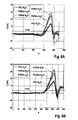
- Fig. 7 shows the measurement results for six clamping units 1 to 6 of the same type and four different PVC hoses and four different PUR hoses and another hose CBN made of a different material, the PVC hoses in Fig. 7 with rectangles and the PUR hoses are marked with circles.
- the range of values in which reliable identification of the type of hose is not guaranteed lies between the upper limit value specified in Fig. 7 is marked with the upper horizontal line (limit (PUR)) and the lower limit marked with the lower line (limit (PVC)).
- the safety distance between the upper and lower lines is calculated from the quotient of the difference between the upper limit (PUR) and the lower limit (PVC) and the mean of the limit values.
- the measurement procedure described above was tested with four Clamping Units A, B, C, D, using a thin PUR hose with a small wall thickness, a thick PUR hose with a large wall thickness and a standard PVC hose.
- the tube was filled with water, which has a temperature of 36.6 °. The water would be pumped through the hoses.
- FIGS. 8A to 8D show the over 10 points smoothed motor current I [mA] as a function of the motor distance x for each Einspannechen A, B, C, D, where the thin PUR tube with a small wall thickness with PURdu, the thick PUR tube with a large wall thickness with PURdi and the standard PVC hose with PVC is designated.
- the predetermined constant current I 0 is 5 mA.
- Fig. 9 shows a table in which the integral A, the maximum current I max and the slope of the flank dI / dx for the individual clamping units A, B, C, D and the different types of hose PVC and PUR is entered.
- the safety requirement is indicated in the table by ⁇ .
Abstract
Die Erfindung betrifft eine Vorrichtung zum Einspannen einer Schlauchleitung mit einer Einspanneinheit insbesondere einer Vorrichtung zur Bestimmung der Konzentration eines Bestandteils von Blut in einer Schlauchleitung, insbesondere einer Schlauchleitung eines extrakorporalen Blutkreislaufs einer extrakorporalen Blutbehandlungsvorrichtung. Darüber hinaus betrifft die Erfindung ein Verfahren zur Erkennung einer Schlauchleitung, insbesondere einer Schlauchleitung eines extrakorporalen Blutkreislaufs einer extrakorporalen Blutbehandlungsvorrichtung, in einer Einspanneinheit insbesondere einer Vorrichtung zur Bestimmung der Konzentration eines Blutbestandteils in einer Schlauchleitung. Die erfindungsgemäße Vorrichtung zeichnet sich durch eine Einspanneinheit 12 aus, die einen Betätigungsmechanismus 18 aufweist, der derart ausgebildet ist, dass unter Aufbringung einer Spannkraft ein erstes und zweites Aufnahmeelement 15, 16 aus einer ersten die Schlauchleitung freigebenden Stellung in eine zweite die Schlauchleitung einspannende Stellung gegeneinander bewegbar sind, wobei der Antrieb des Betätigungsmechanismus mit einem Elektromotor 19 erfolgt. Darüber hinaus zeichnet sich die erfindungsgemäße Vorrichtung durch eine Überwachungseinheit 27 aus, die derart ausgebildet ist, dass die in die Aufnahmeelemente 15, 16 eingelegte Schlauchleitung 17 erkennbar ist. Dadurch ist eine Automatisierung der Messung der Blutparameter möglich.The invention relates to a device for clamping a tubing with a clamping unit, in particular a device for determining the concentration of a component of blood in a tubing, in particular a tubing of an extracorporeal blood circulation of an extracorporeal blood treatment device. Moreover, the invention relates to a method for detecting a tubing, in particular a tubing of an extracorporeal blood circulation of an extracorporeal blood treatment device, in a clamping unit, in particular a device for determining the concentration of a blood component in a tubing. The device according to the invention is characterized by a clamping unit 12, which has an actuating mechanism 18 which is designed in such a way that a first and second receiving element 15, 16 from a first position releasing the hose line into a second position clamping the hose line against one another while applying a clamping force are movable, wherein the drive of the actuating mechanism is carried out with an electric motor 19. In addition, the device according to the invention is characterized by a monitoring unit 27, which is designed such that the inserted into the receiving elements 15, 16 hose 17 is visible. This makes it possible to automate the measurement of blood parameters.
Description
Die Erfindung betrifft eine Vorrichtung zum Einspannen einer Schlauchleitung mit einer Einspanneinheit insbesondere einer Vorrichtung zur Bestimmung der Konzentration eines Bestandteils von Blut in einer Schlauchleitung, insbesondere einer Schlauchleitung eines extrakorporalen Blutkreislaufs einer extrakorporalen Blutbehandlungsvorrichtung. Darüber hinaus betrifft die Erfindung ein Verfahren zur Erkennung einer Schlauchleitung, insbesondere einer Schlauchleitung eines extrakorporalen Blutkreislaufs einer extrakorporalen Blutbehandlungsvorrichtung, in einer Einspanneinheit insbesondere einer Vorrichtung zur Bestimmung der Konzentration eines Blutbestandteils in einer Schlauchleitung.The invention relates to a device for clamping a tubing with a clamping unit, in particular a device for determining the concentration of a component of blood in a tubing, in particular a tubing of an extracorporeal blood circulation of an extracorporeal blood treatment device. Moreover, the invention relates to a method for detecting a tubing, in particular a tubing of an extracorporeal blood circulation of an extracorporeal blood treatment device, in a clamping unit, in particular a device for determining the concentration of a blood component in a tubing.
Zur Bestimmung der Konzentration von bestimmten Bestandteilen im Blut eines Patienten sind verschiedene Verfahren bekannt. Im Stand der Technik sind Verfahren zur Messung der Konzentration von Blutbestandteilen bekannt, die eine Entnahme einer Blutprobe voraussetzen. Es sind aber auch Messverfahren bekannt, bei denen die Konzentration von Blutbestandteilen gemessen wird, während das Blut durch die Schlauchleitung strömt. Diese Verfahren finden insbesondere dann Anwendung, wenn bei einer extrakorporalen Blutbehandlung das Blut in der Schlauchleitung eines extrakorporalen Blutkreislaufs fließt.Various methods are known for determining the concentration of certain constituents in the blood of a patient. In the prior art, methods for measuring the concentration of blood components are known, which require a blood sample to be taken. However, measuring methods are also known in which the concentration of blood constituents is measured while the blood flows through the tubing. These methods are used in particular when in an extracorporeal blood treatment the blood flows in the tubing of an extracorporeal blood circulation.
Die
Aus der
Darüber hinaus wird angestrebt, dass reproduzierbare Messungen der Blutparameter für den Anwender ohne großen Aufwand möglich sind. Eine Automatisierung des Messablaufs setzt auch die Erkennung der in die Einspanneinheit eingelegten Schlauchleitungen voraus. Auch spielt bei der Messung in der Praxis die Leistung und Lebensdauer der als Lichtemitter verwendeten Leuchtdioden (LEDs) eine Rolle.In addition, it is desirable that reproducible measurements of the blood parameters are possible for the user without much effort. Automation of the measuring sequence also requires the detection of the hose lines inserted in the clamping unit. The performance and lifetime of the light-emitting diodes (LEDs) used as light emitters also play a role in the measurement in practice.
Der Erfindung liegt die Aufgabe zugrunde, eine Vorrichtung zum Einspannen einer Schlauchleitung zu schaffen, die eine Erkennung einer in die Aufnahmeelemente einer Einspanneinheit der Vorrichtung zum Einspannen der Schlauchleitung eingelegten Schlauchleitung erlaubt, insbesondere eine Vorrichtung zur Bestimmung der Konzentration von Blutparametern in einer Schlauchleitung zu schaffen, die einen automatisierten Messablauf mit hoher Messgenauigkeit und die Erkennung einer in die Aufnahmeelemente der Einspanneinheit der Vorrichtung zur Bestimmung der Konzentration von Blutparametern eingelegten Schlauchleitung erlaubt.The invention has for its object to provide a device for clamping a tubing, which allows detection of a inserted into the receiving elements of a clamping unit of the device for clamping the tubing tubing, in particular to provide a device for determining the concentration of blood parameters in a tubing, which allows an automated measurement procedure with high measurement accuracy and the detection of a tube inserted into the receiving elements of the clamping unit of the device for determining the concentration of blood parameters.
Eine weitere Aufgabe der Erfindung ist ein Verfahren zur Erkennung einer Schlauchleitung in einer Einspanneinheit einer Vorrichtung zum Einspannen einer Schlauchleitung insbesondere einer Vorrichtung zur Bestimmung der Konzentration eines Blutbestandteils anzugeben.Another object of the invention is a method for detecting a hose in a clamping unit of a device for clamping a Specify tubing in particular a device for determining the concentration of a blood component.
Die erfindungsgemäße Vorrichtung zur Bestimmung der Konzentration eines Bestandteils von Blut in einer Schlauchleitung, insbesondere der Schlauchleitung eines extrakorporalen Blutkreislaufs, zeichnet sich dadurch aus, dass die Einspanneinheit einen Betätigungsmechanismus aufweist, der derart ausgebildet ist, dass unter Aufbringung einer Spannkraft ein erstes und zweites Aufnahmeelement aus einer ersten die Schlauchleitung freigebenden Stellung in eine zweite die Schlauchleitung einspannende Stellung gegeneinander bewegbar sind, wobei der Antrieb des Betätigungsmechanismus mit einem Elektromotor erfolgt. Dadurch wird eine voll automatisch arbeitende Einspanneinheit geschaffen, in die der Benutzer die Schlauchleitung nur einzulegen braucht.The inventive device for determining the concentration of a component of blood in a tubing, in particular the tubing of an extracorporeal blood circulation, characterized in that the clamping unit has an actuating mechanism which is designed such that upon application of a clamping force, a first and second receiving element a first position releasing the hose line are movable relative to one another in a second position clamping the hose line, the drive of the actuating mechanism being effected with an electric motor. This creates a fully automatic clamping unit, in which the user only needs to insert the hose line.
Da die beiden Aufnahmeelemente für die Schlauchleitung elektromotorisch gegeneinander verfahren werden, wird die erforderliche Spannkraft gleichmäßig aufgebracht. Der elektromotorische Antrieb erlaubt die Einstellung einer bestimmten Vorschubgeschwindigkeit, mit der die Aufnahmeelemente bewegt werden. Damit ist es möglich, die Schlauchleitung mit einer optimalen Vorschubgeschwindigkeit zusammen zu drücken, so dass die Schlauchleitung Gelegenheit hat, sich zwischen den Aufnahmeelementen exakt zu zentrieren. Dadurch wird ein Verklemmen der Schlauchleitung in Folge einer zu schnellen und nicht gleichförmigen Bewegung der Spannelemente vermieden.Since the two receiving elements for the hose line are moved by an electric motor against each other, the required clamping force is applied evenly. The electromotive drive allows the setting of a certain feed rate at which the receiving elements are moved. This makes it possible to press the hose together with an optimum feed rate, so that the hose line has the opportunity to center exactly between the receiving elements. As a result, jamming of the tubing as a result of too fast and not uniform movement of the clamping elements is avoided.
Darüber hinaus zeichnet sich die erfindungsgemäße Vorrichtung zur Bestimmung der Konzentration von Blutbestandteilen durch eine Überwachungseinheit aus, die derart ausgebildet ist, dass die in die Aufnahmeelemente eingelegte Schlauchleitung erkennbar ist. Dadurch ist eine Automatisierung der Messung der Blutparameter möglich. Beispielsweise kann die Messung erst und nur dann gestartet werden, wenn die Schlauchleitung in die Einspanneinheit eingelegt ist. Damit kann die Leuchtdauer der als Lichtemitter verwendeten LEDs verringert werden, so dass sich die Lebensdauer des LEDs erhöht. Im Übrigen werden Fehlmessungen bei nicht eingelegter Schlauchleitung vermieden.In addition, the device according to the invention for determining the concentration of blood components is characterized by a monitoring unit which is designed such that the tube inserted into the receiving elements can be seen. This makes it possible to automate the measurement of blood parameters. For example, the measurement can only be started if and only if the hose line is inserted into the clamping unit. Thus, the lighting duration of the LEDs used as a light emitter can be reduced, so that increases the life of the LEDs. Incidentally, incorrect measurements are avoided when not inserted hose.
Bei der erfindungsgemäßen Vorrichtung wird zur Erkennung der Schlauchleitung in der Einspanneinheit der Motorstrom des Elektromotors zum Antrieb des Betätigungsmechanismus der Einspanneinheit gemessen, wobei auf der Grundlage der Veränderung des gemessenen Motorstroms die in die Aufnahmeelemente der Einspanneinheit eingelegte Schlauchleitung erkannt wird. Anstelle des Motorstroms des Elektromotors zum Antrieb des Betätigungsmechanismus kann auch jede mit dem Motorstrom korrelierende Größe, bspw. die Motorleistung, ausgewertet werden. Die Auswertung des Motorstroms zur Erkennung der Schlauchleitung kann in einer Rechen- und Auswerteinheit erfolgen, ohne dass weitere mechanische Komponenten erforderlich sind. Die Rechen- und Auswerteinheit der Überwachungseinheit kann Bestandteil der Rechen- und Auswerteinheit der Vorrichtung zur Bestimmung der Konzentration des Blutbestandteils sein. Beide Rechen- und Auswerteinheiten können auch Bestandteil der zentralen Steuereinheit oder Rechen- und Auswerteinheit einer extrakorporalen Blutbehandlungsvorrichtung sein.In the apparatus according to the invention, the motor current of the electric motor for driving the actuating mechanism of the clamping unit is measured for detecting the hose in the clamping unit, wherein on the basis of the change in the measured motor current, the inserted into the receiving elements of the clamping unit hose is detected. Instead of the motor current of the electric motor for driving the actuating mechanism, any variable correlating with the motor current, for example the motor power, can also be evaluated. The evaluation of the motor current for the detection of the hose can be done in a computing and evaluation unit, without further mechanical components are required. The computing and evaluation unit of the monitoring unit can be part of the computing and evaluation unit of the device for determining the concentration of the blood component. Both arithmetic and evaluation units can also be part of the central control unit or arithmetic and evaluation unit of an extracorporeal blood treatment device.
Es hat sich gezeigt, dass der Motorstrom einen charakteristischen Verlauf hat, der davon abhängig ist, ob eine Schlauchleitung eingespannt wird oder nicht. Beim Schließen der Aufnahmeelemente zeigt sich ein deutlicher Anstieg des Motorstroms wesentlich früher, wenn die Schlauchleitung in die Aufnahmeelemente eingelegt ist. Auch ist bei eingelegter Schlauchleitung der Anstieg des Motorstroms deutlich steiler. Somit kann der zeitliche Verlauf des Motorstroms beim Schließen der Aufnahmeelemente als Kriterium für die Erkennung der Schlauchleitung herangezogen werden.It has been shown that the motor current has a characteristic course, which depends on whether a hose is clamped or not. When closing the receiving elements, a significant increase in the motor current shows much earlier, when the hose is inserted into the receiving elements. Also, when the hose is inserted, the increase of the motor current is significantly steeper. Thus, the time course of the motor current when closing the receiving elements can be used as a criterion for the detection of the hose.
Bei einer besonders bevorzugten Ausführungsform verfügt die Überwachungseinheit über Mittel zum Messen der von den Aufnahmeelementen zurückgelegten Wegstrecke, wobei die Rechen- und Auswerteinheit der Überwachungseinheit derart ausgebildet ist, dass der Motorstrom in Abhängigkeit von der von den Aufnahmeelementen zurückgelegten Wegstrecke ausgewertet wird. Die Rechen- und Auswerteinheit ist bei der besonders bevorzugten Ausführungsform derart ausgebildet, dass das Integral des Motorstroms über eine vorgegebene von den Aufnahmeelementen zurückgelegte Wegstrecke mit einem vorgegebenen Grenzwert verglichen wird, wobei bei Überschreiten des Grenzwertes darauf geschlossen wird, dass in die Aufnahmeelemente eine Schlauchleitung eingelegt ist. Die Integration des Motorstroms braucht nicht kontinuierlich, sondern kann auch in diskreten Zeitintervallen erfolgen. Der Grenzwert kann in Abhängigkeit von dem Material der verwendeten Schlauchleitung vorgegeben werden, wobei für verschiedene Schlauchleitungen auch mehrere Grenzwerte vorgegeben werden können.In a particularly preferred embodiment, the monitoring unit has means for measuring the distance covered by the receiving elements, wherein the computing and evaluation of the monitoring unit is designed such that the motor current is evaluated in dependence on the distance covered by the receiving elements. The arithmetic and evaluation unit is formed in the particularly preferred embodiment such that the integral of the motor current is compared over a predetermined distance traveled by the receiving elements distance with a predetermined limit, wherein when the limit value is exceeded it is concluded that in the receiving elements a hose is inserted. The integration of the motor current does not need continuous, but can also be done in discrete time intervals. The limit value can be specified as a function of the material of the hose line used, with it also being possible to specify a plurality of limit values for different hose lines.
Eine besondere Ausführungsform der Einspanneinheit, die von eigener erfinderischer Bedeutung ist, zeichnet sich dadurch aus, dass das erste Aufnahmeelement zwei rechtwinklig zueinander stehende ebene Anlageflächen und das zweite Aufnahmeelement zwei rechtwinklig zueinander stehende ebene Anlageflächen aufweist, wobei das erste und zweite Aufnahmeelement auf einer Achse gegeneinander bewegbar sind, die mit den ebenen Anlageflächen des ersten und zweiten Aufnahmeelements einen Winkel von 45° einschließt. Dabei ist unerheblich, wie die beiden Aufnahmeelemente ausgebildet sind, solange die rechtwinklig zueinander stehenden ebenen Anlageflächen vorhanden sind.A particular embodiment of the clamping unit, which has its own inventive significance, is characterized in that the first receiving element has two mutually perpendicular planar contact surfaces and the second receiving element has two mutually perpendicular planar contact surfaces, wherein the first and second receiving element on an axis against each other are movable, which forms an angle of 45 ° with the flat contact surfaces of the first and second receiving element. It is irrelevant how the two receiving elements are formed, as long as the mutually perpendicular planar contact surfaces are present.
Die Aufnahmeelemente mit den ebenen Anlageflächen verformen die Schlauchleitung beim Schließen der Einspanneinheit. Vorzugsweise weisen das erste und zweite Aufnahmeelement zu beiden Seiten der ebenen Anlageflächen halbzylindrische Anlageflächen auf. In dem Bereich der halbzylindrischen Anlageflächen wird die eingelegte Schlauchleitung nicht verformt.The receiving elements with the flat contact surfaces deform the hose when closing the clamping unit. Preferably, the first and second receiving element on both sides of the planar contact surfaces on semi-cylindrical contact surfaces. In the area of the semi-cylindrical contact surfaces, the inserted hose line is not deformed.
Eine besonders bevorzugte Ausführungsform sieht zwischen den ebenen Anlageflächen und den halbzylindrischen Anlageflächen der beiden Aufnahmeelemente einen Übergangsabschnitt vor, der derart ausgebildet ist, dass die inneren ebenen Anlageflächen kontinuierlich in die äußeren halbzylindrischen Anlageflächen übergehen. Dabei ist unter einem kontinuierlichen Übergang jeder Übergang zu verstehen, der eine gleichmäßige Verformung der Schlauchleitung erlaubt, so dass der kreisförmige Querschnitt der Schlauchleitung gleichförmig in den quadratischen Querschnitt übergeht und die Schlauchleitung nicht geknickt wird.A particularly preferred embodiment provides between the flat contact surfaces and the semi-cylindrical contact surfaces of the two receiving elements before a transition section which is formed such that the inner planar contact surfaces continuously merge into the outer semi-cylindrical contact surfaces. In this case, a continuous transition is to be understood as meaning any transition which allows a uniform deformation of the hose line so that the circular cross section of the hose line changes uniformly into the square cross section and the hose line is not kinked.
Der gleichmäßige Übergang von dem kreisförmigen in den quadratischen Querschnitt hat nicht nur den Vorteil, dass die Schlauchleitung beim Schließen der Einspanneinheit geschont wird, sondern auch den Vorteil, dass turbulente Strömungen beim Übergang von dem runden zum quadratischen Leitungsquerschnitt vermieden werden. Dadurch kann die Länge des quadratischen Messkanals, in dem Lichtemitter und Lichtdetektoren angeordnet werden, möglichst gering gehalten werden. Eine Verkürzung des Messkanals hat wiederum kleine Schließkräfte zur Folge, was ebenfalls von Vorteil ist.The smooth transition from the circular to the square cross-section not only has the advantage that the hose when closing the clamping unit is conserved, but also the advantage that turbulent flows are avoided in the transition from the round to the square cross-section. As a result, the length of the square measuring channel in which light emitters and light detectors are arranged can be kept as low as possible. A shortening of the measuring channel in turn has small closing forces result, which is also beneficial.
Die Messeinheit der Vorrichtung zur Bestimmung der Konzentration von Blutbestandteilen weist vorzugsweise mehrere Lichtemitter zum Einkoppeln von elektromagnetischer Strahlung durch die Schlauchleitung in das Blut und mehrere Lichtdetektoren zum Messen der durch die Schlauchleitung aus dem Blut austretenden elektromagnetischen Strahlung auf, die in dem ersten und zweiten Aufnahmeelement angeordnet sind. Vorzugsweise sind die Lichtemitter und Lichtdetektoren in Lichtaustritts- und -eintrittsöffnungen angeordnet, die in den ebenen Anlageflächen der Aufnahmeelemente vorgesehen sind. Damit sind die Lichtemitter und Lichtdetektoren in die Aufnahmeelemente integriert.The measuring unit of the device for determining the concentration of blood constituents preferably comprises a plurality of light emitters for injecting electromagnetic radiation through the tubing into the blood and a plurality of light detectors for measuring the electromagnetic radiation emerging from the blood through the tubing disposed in the first and second receiving elements are. Preferably, the light emitters and light detectors are arranged in light exit and -eintrittsöffnungen, which are provided in the planar contact surfaces of the receiving elements. Thus, the light emitters and light detectors are integrated into the receiving elements.
Bei einer bevorzugten Ausführungsform der Messeinheit, die von eigener erfinderischer Bedeutung ist, sind mindestens einem Lichtdetektor mindestens eine Gruppe von zwei Lichtemittern zugeordnet. Es können dem mindestens einen Lichtdetektor bspw. 2, 4, 6 oder 8 Lichtemitter zugeordnet werden. In der Praxis ist aber die Zuordnung von 2 Lichtemittern zu einem Lichtdetektor ausreichend.In a preferred embodiment of the measuring unit, which has its own inventive significance, at least one light detector is associated with at least one group of two light emitters. It can be assigned to the at least one light detector, for example 2, 4, 6 or 8 light emitters. In practice, however, the assignment of 2 light emitters to a light detector is sufficient.
Die Verwendung von zwei Lichtemittern anstelle nur eines Lichtemitters zum Einkoppeln von Licht in die Schlauchleitung hat den Vorteil, dass die Lichtausbeute der LEDs verdoppelt wird, während die Einflüsse der Schlauchleitung auf die von dem Licht zurückgelegte Strecke verringert wird.The use of two light emitters instead of only one light emitter for coupling light into the tubing has the advantage that the luminous efficiency of the LEDs is doubled while the influence of the tubing on the distance traveled by the light is reduced.
Nachteilig ist, dass die Signalamplitude mit zunehmendem Abstand von Lichtemitter und Lichtdetektor abnimmt. Daher wird grundsätzlich eine Erhöhung der Intensität des eingekoppelten Lichts angestrebt. Dies schränkt aber die Auswahl der als Lichtemitter zur Verfügung stehenden Bauelemente stark ein. Ein geringerer Abstand von Lichtemittern und Lichtdetektoren, der eine Erhöhung der Intensität der Strahlung nicht erforderlich macht, beeinträchtigt hingegen die Genauigkeit der Messung. Dazu kommen Veränderungen der Schlauchwandstärke, die bei den bekannten Extrusionsprozessen zur Herstellung der Schlauchleitungen auf kurzen Abschnitten der Schlauchleitungen nicht auszuschließen sind. So hat der Schlauch nur in erster Näherung über seinen ganzen Umfang dieselbe Wandstärke.The disadvantage is that the signal amplitude decreases with increasing distance from the light emitter and the light detector. Therefore, in principle, an increase in the intensity of the injected light is sought. However, this greatly restricts the selection of the components available as light emitters. A shorter distance from light emitters and light detectors, which does not require an increase in the intensity of the radiation makes, however, affects the accuracy of the measurement. In addition, there are changes in the hose wall thickness, which can not be excluded in the known extrusion processes for the production of hose lines on short sections of the hose lines. Thus, the hose has only the first approximation over its entire circumference the same wall thickness.
Die Zusammenfassung von zwei auf einandergegenüberliegenden Seiten der Schlauchleitung angeordneten Lichtemittern zu einer Gruppe verdoppelt die Lichtausbeute. Da das Licht beider Lichtemitter auf unterschiedlichen Messstrecken ausgewertet wird, werden die Einflüsse der Schlauchleitung gemittelt, wodurch die Messgenauigkeit erhöht wird.The combination of two light emitters arranged on opposite sides of the tubing into a group doubles the luminous efficacy. Since the light of both light emitters is evaluated on different measuring sections, the influences of the hose line are averaged, whereby the measuring accuracy is increased.
Die besondere Ausbildung der Aufnahmeelemente der Einspanneinheit mit den ebenen und zylindrischen Anlageflächen setzt nicht zwingend die besondere Ausbildung der Messeinheit und besondere Ausbildung der Einspanneinheit mit dem Betätigungsmechanismus voraus, der über einen elektromotorischen Antrieb verfügt. Auch die besondere Ausbildung der Messeinheit setzt nicht die besondere Ausbildung der Aufnahmeelemente der Einspanneinheit und die besondere Ausbildung des elektromotorisch angetriebenen Betätigungsmechanismus der Einspanneinheit voraus.The special design of the receiving elements of the clamping unit with the flat and cylindrical contact surfaces does not necessarily require the special design of the measuring unit and special design of the clamping unit with the actuating mechanism, which has an electric motor drive. The special design of the measuring unit does not require the special design of the receiving elements of the clamping unit and the special design of the electric motor-driven actuating mechanism of the clamping unit.
Im Folgenden wird ein Ausführungsbeispiel der Erfindung unter Bezugnahme auf die Zeichnungen näher erläutert.In the following an embodiment of the invention will be explained in more detail with reference to the drawings.
Es zeigen:
-
Fig. 1 eine Vorrichtung zur extrakorporalen Blutbehandlung zusammen mit einer Vorrichtung zum Bestimmen der Konzentration eines Blutbestandteils in stark vereinfachter schematischer Darstellung, -
Fig. 2A eine stark vereinfachte schematische Darstellung der Einspanneinheit und der Messeinheit der Vorrichtung zur Bestimmung der Konzentration eines Blutbestandteils, wobei die Anordnung der Lichtemitter und Lichtdetektoren in einer ersten Schnittebene gezeigt wird, -
Fig. 2B die Einspanneinheit und Messeinheit in stark vereinfachter schematischer Darstellung, wobei die Anordnung der Lichtemitter und Lichtdetektoren in einer zweiten Schnittebene gezeigt wird, die von der ersten Schnittebene verschieden ist, -
Fig. 3A das eine Aufnahmeelement der Einspanneinheit in perspektivischer Darstellung, -
Fig. 3B das andere Aufnahmeelement der Einspanneinheit in perspektivischer Darstellung, -
Fig. 4A den zeitlichen Verlauf des bei einer ersten Einspanneinheit gemessenen Motorstroms des Elektromotors für die elektromotorische Betätigung der Einspanneinheit, -
Fig. 4B den zeitlichen Verlauf des bei einer zweiten Einspanneinheit gemessenen Motorstroms, -
Fig. 4C den zeitlichen Verlauf des bei einer dritten Einspanneinheit gemessenen Motorstroms, -
Fig. 5 eine Auswertung der Messergebnisse von denFig. 4A - 4C , -
Fig. 6 den Motorstrom in Abhängigkeit von dem Drehmoment, -
Fig. 7 die Messergebnisse für sechs Einspanneinheiten der gleichen Bauart und unterschiedliche Schlauchleitungen, -
Fig. 8A bis Fig. 8D den Motorstrom I als Funktion der Motorstrecke x für die Einspanneinheiten der gleichen Bauart und die unterschiedlichen Schlauchtypen und -
Fig. 9 eine Tabelle, in der das Integral, der maximale Strom und die Steigung der Stromanstiegsflanke für die Einspanneinheiten der gleichen Bauart und die unterschiedlichen Schlauchtypen eingetragen ist.
-
Fig. 1 a device for extracorporeal blood treatment together with a device for determining the concentration of a blood component in a highly simplified schematic representation, -
Fig. 2A a greatly simplified schematic representation of the clamping unit and the measuring unit of the device for determining the concentration of a Blood component, wherein the arrangement of the light emitters and light detectors is shown in a first sectional plane, -
Fig. 2B the clamping unit and measuring unit in a highly simplified schematic representation, wherein the arrangement of the light emitter and light detectors is shown in a second sectional plane, which is different from the first sectional plane, -
Fig. 3A the one receiving element of the clamping unit in a perspective view, -
Fig. 3B the other receiving element of the clamping unit in a perspective view, -
Fig. 4A the time profile of the measured during a first clamping unit motor current of the electric motor for the electromotive actuation of the clamping unit, -
Fig. 4B the time course of the motor current measured in a second clamping unit, -
Fig. 4C the time course of the motor current measured in a third clamping unit, -
Fig. 5 an evaluation of the results of theFig. 4A - 4C . -
Fig. 6 the motor current as a function of the torque, -
Fig. 7 the measurement results for six clamping units of the same type and different hose lines, -
8A to Fig. 8D the motor current I as a function of the motor distance x for the clamping units of the same type and the different types of hoses and -
Fig. 9 a table in which the integral, the maximum current and the slope of the current rising edge are entered for the clamping units of the same type and the different types of hoses.
Die Vorrichtung 11 zur Bestimmung der Konzentration von bestimmten Bestandteilen im Blut des Patienten kann Bestandteil der extrakorporalen Blutbehandlungsvorrichtung sein oder eine separate Baugruppe bilden. Wenn die Vorrichtung 11 Bestandteil der Blutbehandlungsvorrichtung ist, kann sie von den Komponenten Gebrauch machen, die in der Blutbehandlungsvorrichtung ohnehin vorhanden sind.The
Die Vorrichtung 11 zum Bestimmen der Konzentration von Blutbestandteilen, insbesondere der Hämoglobinkonzentration (Hb), des Hämatokrit (Hkt) oder des relativen Blutvolumens (RBV) verfügt über eine in
Bei dem vorliegenden Ausführungsbeispiel ist die Rechen- und Auswerteinheit 14 zum Bestimmen der Konzentration eines Blutbestandteils Bestandteil der zentralen Steuereinheit 10 oder Rechen- und Auswerteinheit der extrakorporalen Blutbehandlungsvorrichtung. Es können aber auch getrennte Einheiten vorgesehen sein.In the present exemplary embodiment, the arithmetic and
Die
Die Einspanneinheit 12 weist zwei Aufnahmeelemente 15, 16 auf, zwischen denen die Schlauchleitung 17 eingespannt wird, so dass die runde Schlauchleitung einen quadratischen Querschnitt erhält. Zum Einlegen der Schlauchleitung können die Aufnahmeelemente 15, 16 entlang einer Achse a gegeneinander verfahren werden. Zum Bewegen der Einspannelemente 15, 16 aus einer die Schlauchleitung 17 freigebenden Stellung in eine die Schlauchleitung einspannende Stellung dient ein Betätigungsmechanismus 18, der in den
Die Aufnahmeelemente 15, 16 und der Betätigungsmechanismus 18 können unterschiedlich ausgebildet sein. Zum Antrieb des Betätigungsmechanismus 18 dient ein Elektromotor 19, der ebenfalls nur schematisch dargestellt ist. Wenn der Elektromotor in die eine oder andere Richtung dreht, werden die Aufnahmeelemente entlang der Achse a auf- und zugefahren. Die
Die Aufnahmeelemente 15, 16 weisen jeweils zwei ebene Anlageflächen 15A, 15B bzw. 16A, 16B auf, die jeweils einen rechten Winkel einschließen. Die Achse a, auf der die Aufnahmeelemente 15, 16 verfahren werden, schließen mit den ebenen Anlageflächen 15A, 15B bzw. 16A, 16B einen Winkel von 45° ein.The receiving
Die Messeinheit 13 verfügt über mehrere Lichtemitter 20A, 20B; 21A, 21B, die in einer ersten Ebene (
Bei der erfindungsgemäßen Messeinheit sind mindestens einem der Lichtdetektoren 22A - 22D jeweils zwei Lichtemitter 20A, 20B bzw. 21A, 21B zugeordnet, die gleichzeitig Licht aussenden, das der mindestens eine Lichtdetektor 22A - 22D empfängt. Die beiden Lichtemitter einer Gruppe von Lichtemittern, bspw. die Lichtemitter 20A und 20B liegen sich einander gegenüber. Der zugehörige Lichtdetektor 22A - 22D ist in einer Ebene angeordnet, die mit der Ebene, in der die Lichtemitter 20A, 20B angeordnet sind, einen Winkel von 90° einschließt.In the measuring unit according to the invention, at least one of the
Mit der erfindungsgemäßen Messeinheit wird die Lichtausbeute verdoppelt, da das Licht von jeweils zwei Lichtemittern mit den Lichtdetektoren ausgewertet wird. Darüber hinaus wird der Einfluss unterschiedlicher Schlauchdicken innerhalb des Messkanals auf das Messergebnis reduziert, da die Messung über unterschiedliche Messstrecken erfolgt.With the measuring unit according to the invention, the light output is doubled, since the light is evaluated by two light emitters with the light detectors. In addition, the influence of different tube thicknesses within the measuring channel on the measurement result is reduced because the measurement is carried out over different measuring distances.
Während die Einspanneinheit 12 in den
Die beiden Aufnahmeelemente 15, 16 werden wieder mit einem in den
Die Aufnahmeelemente bilden in der geschlossenen Stellung einen Messkanal 23, der einen inneren Abschnitt 23A und zwei äußere Abschnitte 23B, 23C umfasst, die zu beiden Seiten des inneren Abschnitt 23A angeordnet sind. Innerhalb des inneren Abschnitts 23A weist der Aufnahmekanal den in den
In dem inneren Abschnitt 23A weist jedes Aufnahmeelement 15, 16 zwei rechtwinklig zueinander stehende ebene Anlageflächen und in den äußeren Abschnitten 23B, 23C jeweils eine halbzylindrische Anlagefläche auf, die sich zu dem quadratischen bzw. kreisförmigen Messkanal in der geschlossenen Stellung der Einspanneinheit ergänzen. Zwischen den halbzylindrischen Anlageflächen der äußeren Abschnitte 23B, 23C und den beiden ebenen Anlageflächen des inneren Abschnitts 23A jedes Aufnahmeelements 15, 16 befindet sich ein Übergangsabschnitt 24B, 24C, in dem die halbzylindrischen Anlageflächen kontinuierlich in die ebenen Anlageflächen übergehen. Dadurch wird die Schlauchleitung einerseits nicht geknickt und andererseits wird die Bildung von Turbulenzen vermieden, wenn die Schlauchleitung von Blut durchströmt wird.In the
Die Lichtemitter 20A, 20B, 21A, 21B und die Lichtdetektoren 22A - 22C sind innerhalb des quadratischen Messkanals in den inneren Abschnitten 23A der Aufnahmeelemente 15, 16 angeordnet. Die ebenen Anlageflächen der Aufnahmeelemente weisen entsprechende Lichtaustritts- und -eintrittsöffnungen 25, 26 auf.The
Zur Erkennung der Schlauchleitung 17 in der Einspanneinheit 12 weist die Vorrichtung 11 zur Bestimmung der Konzentration von Blutbestandteilen eine Überwachungseinheit 27 auf (
Die Rechen- und Auswerteinheit 27C der Überwachungseinheit 27 berechnet das Integral des gemessenen Motorstroms über eine Wegstrecke, die von den Aufnahmeelementen 15, 16 beim Schließen der Einspanneinheit 12 zurückgelegt wird. Das berechnete Integral des Motorstroms wird mit einem vorgegebenen Grenzwert verglichen. Wenn der Grenzwert überschritten wird, stellt die Rechen- und Auswerteinheit 27C der Überwachungseinheit 27 fest, dass eine Schlauchleitung in die Einspanneinheit 12 eingelegt ist. Ansonsten stellt die Rechen- und Auswerteinheit fest, dass eine Schlauchleitung nicht eingelegt ist. In beiden Fällen erzeugt die Rechen- und Auswerteinheit ein entsprechendes Signal, das die zentrale Steuereinheit der Blutbehandlungsvorrichtung empfängt. Im Einzelnen arbeitet die Rechen- und Steuereinheit 27C der Überwachungseinheit 27 wie folgt:The computing and
Der Verlauf des Motorstroms wird über ein bestimmtes Wegstreckenintervall überwacht. Bei dem vorliegenden Ausführungsbeispiel ist der Anfang der Wegstrecke N1 = 250 und das Ende der Wegstrecke N2 = 350 (
Die Rechen- und Auswerteinheit berechnet für die vorgegebene Wegstrecke zwischen N1 und N2 das Integral wie folgt: 
Die
Die
- 5:
- Einspanneinheit ohne Schlauch
- 1a:
- PVC-Schlauch (Standardwandstärke) in Einspanneinheit
- 1b:
- mit H2O gefüllter PVC-Schlauch (Standardwandstärke) in Einspanneinheit
- 2a:
- PVC-Schlauch (dünne Wandstärke) in Einspanneinheit
- 2b:
- mit H2O gefüllter PVC-Schlauch (dünne Wandstärke) in Einspanneinheit
- 3a:
- PVC-Schlauch (dicke Wandstärke) in Einspanneinheit
- 3b:
- mit H2O gefüllter PVC-Schlauch (dicke Wandstärke) in Einspanneinheit
- 4a:
- leerer Schlauch (anderes Material) in Einspanneinheit
- 4b:
- mit H2O gefüllter Schlauch (anderes Material) in Einspanneinheit
- 5:
- Clamping unit without hose
- 1a:
- PVC hose (standard wall thickness) in clamping unit
- 1b:
- filled with H 2 O PVC hose (standard wall thickness) in clamping unit
- 2a:
- PVC hose (thin wall thickness) in clamping unit
- 2 B:
- filled with H 2 O PVC hose (thin wall thickness) in clamping unit
- 3a:
- PVC hose (thick wall thickness) in clamping unit
- 3b:
- filled with H 2 O PVC hose (thick wall thickness) in clamping unit
- 4a:
- empty hose (other material) in clamping unit
- 4b:
- H 2 O filled hose (other material) in clamping unit
Für sämtliche Messungen bei unterschiedlichen Schlauchleitungen und unterschiedlichen Einspanneinheiten zeigt sich, wenn die Einspanneinheit geschlossen wird, dass bei eingelegter Schlauchleitung der Motorstrom früher ansteigt als wenn keine Schlauchleitung eingelegt ist. Darüber hinaus zeigt sich, dass der Stromanstieg bei eingelegter Schlauchleitung stärker ist als wenn keine Schlauchleitung eingelegt ist. Folglich ist die Fläche unter den Kurven bei eingelegter Schlauchleitung größer als bei nicht eingelegter Schlauchleitung.For all measurements with different hose lines and different clamping units shows, when the clamping unit is closed, that when the hose is inserted, the motor current rises earlier than if no hose is inserted. In addition, it can be seen that the current increase is greater when the hose line is inserted than when no hose line is inserted. Consequently, the area under the curves is greater when the hose is inserted than when the hose is not in place.
Bei dem vorliegenden Ausführungsbeispiel wird als vorgegebener Grenzwert für den Wert des Integrals 2000 angenommen. Damit können für sämtliche Schläuche, bei unterschiedlichen Einspanneinheiten sicher zwischen dem Fall, dass ein Schlauch in die Einspanneinheit eingelegt ist, und dem Fall, dass ein Schlauch nicht in die Einspanneinheit eingelegt ist, unterschieden werden. Wenn der Schlauch (anderes Material) nicht verwendet wird, kann der vorgegebene Grenzwert höher liegen. Am vorliegenden Ausführungsbeispiel wird ein Grenzwert von 3000 festgelegt.In the present embodiment, it is assumed as a predetermined limit value for the value of the integral 2000. Thus, for all hoses, with different clamping units, a distinction can be made between the case in which a hose is inserted into the clamping unit and the case where a hose is not inserted into the clamping unit. If the hose (other material) is not used, the preset limit may be higher. In the present embodiment, a limit of 3000 is set.
Für die Messung des Blutvolumens können Blutschläuche aus PVC oder PUR oder anderen Materialien verwendet werden. In der Praxis stellt sich daher nicht nur das Problem der Erkennung eines Blutschlauchs in der Einspanneinheit der Vorrichtung zur Bestimmung der Konzentration eines Blutbestandteils, sondern auch der Identifizierung des in die Einspanneinheit eingelegten Blutschlauchtyps.To measure the blood volume, blood tubes made of PVC or PUR or other materials can be used. In practice, therefore, not only the problem of detecting a blood tube in the clamping unit of the device for determining the concentration of a blood component, but also the identification of the inserted into the clamping unit blood tube type.
Es hat sich in der Praxis gezeigt, dass das Material, aus dem der Blutschlauch besteht, einen Einfluss auf die Genauigkeit der Messung der Konzentration eines Blutbestandteils haben kann. Daher erlaubt die Identifizierung des Blutschlauchs, auch auf die Genauigkeit der Messung zu schließen. So ist es möglich, einen akustischen und/oder optischen Hinweis auf die Messgenauigkeit zu geben. Die Messung kann in Abhängigkeit von dem verwendeten Blutschlauch auch korrigiert oder sogar verhindert werden.It has been shown in practice that the material constituting the blood tube can have an influence on the accuracy of the measurement of the concentration of a blood constituent. Therefore, the identification of the blood tubing also allows to conclude on the accuracy of the measurement. So it is possible to give an acoustic and / or visual indication of the measurement accuracy. The measurement can also be corrected or even prevented depending on the blood tube used.
Im Folgenden wird eine Rechen- und Auswerteinheit der Überwachungseinheit beschrieben, die neben der Erkennung des Blutschlauchs auch die Identifizierung des Blutschlauchtyps erlaubt.In the following, a computing and evaluation unit of the monitoring unit will be described which, in addition to the detection of the blood tube, also permits the identification of the type of blood-tubing.
Mit einem Blutschlauch aus PUR, der sich durch eine geringe Toleranz der Wandstärke auszeichnet, wird in der Praxis eine hohe Messgenauigkeit erzielt. Ein Schlauch aus PUR zeichnet sich im Vergleich zu einem Schlauch aus PVC durch eine größere Härte und eine höhere Elastizität aus. Der PUR-Schlauch übt somit eine größere Rückstellkraft auf die Aufnahmeelemente der Aufnahmeeinheit aus.With a blood tube made of PUR, which is characterized by a low tolerance of the wall thickness, a high measuring accuracy is achieved in practice. A hose made of PUR is characterized by a greater hardness and a higher elasticity compared to a hose made of PVC. The PUR tube thus exerts a greater restoring force on the receiving elements of the receiving unit.
Versuche haben gezeigt, dass sich eine Unterscheidung zwischen einem Blutschlauch aus PUR und PVC mit dem erfindungsgemäßen Verfahren bzw. der erfindungsgemäßen Vorrichtung mit besonders hoher Sicherheit dann treffen lässt, wenn der Blutschlauch vor der Messung für eine vorbestimmte Zeitdauer zwischen den Aufnahmeelementen vorverpresst wird.Experiments have shown that a distinction between a blood tube made of PUR and PVC can be made with the method according to the invention or the device according to the invention with particularly high safety when the blood tube is pre-compressed for a predetermined period of time between the receiving elements before the measurement.
Die erfindungsgemäße Vorrichtung und das erfindungsgemäße Verfahren sehen daher vor, dass nach dem Einlegen der Schlauchleitung in die Einspanneinheit 12 derThe device according to the invention and the method according to the invention therefore provide that after inserting the hose line into the clamping
Betätigungsmechanismus 18 zum Schließen der Aufnahmeelemente 15, 16 in Betrieb gesetzt wird, wobei die Aufnahmeelemente solange geschlossen werden, bis eine vorbestimmte Anpresskraft auf die Schlauchleitung ausgeübt wird, und nach einem vorbestimmten Zeitintervall die Aufnahmeelemente wieder geöffnet werden. Zur Durchführung der eigentlichen Messung werden die Aufnahmeelemente dann wieder geschlossen. Dieser Prozess kann von der Überwachungseinheit 27 vollautomatisch gesteuert werden.
Nachfolgend wird ein Ausführungsbeispiel beschrieben, bei dem eine Kalibrierung zur Erhöhung der Messgenauigkeit vorgesehen ist.Hereinafter, an embodiment will be described in which a calibration for increasing the measurement accuracy is provided.
Das Verhältnis von Strom und Drehmoment wird im Allgemeinen durch die folgende Gleichung beschrieben: 
wobei m das Drehmoment und k eine Konstante und n eine Bezeichnung (Nummer) der bei der Messung verwendeten Einspanneinheit ist.The ratio of current and torque is generally described by the following equation:
where m is the torque and k is a constant and n is a designation (number) of the clamping unit used in the measurement.
Es hat sich gezeigt, dass sich die einzelnen Einspanneinheiten der gleichen Bauart aufgrund von Toleranzen des Betätigungsmechanismus im Schließverhalten voneinander unterscheiden können.It has been found that the individual clamping units of the same type can differ from one another due to tolerances of the actuating mechanism in the closing behavior.
Die Überwachungseinheit 27 ist derart ausgebildet, dass eine Messung mit der folgenden Kalibrierung vorgenommen wird. Sämtliche Rechenoperationen können in einem nicht dargestellten Mikroprozessor ausgeführt werden, der Teil der Überwachungseinheit 27 bzw. der Rechen- und Auswerteinheit 27C ist. Hierzu ist der Mikroprozessor der Rechen-und Auswerteinheit 27C für die Durchführung der folgenden Rechenoperationen programmiert.The
Zunächst werden die Aufnahmeelemente 15, 16 der Einspanneinheit 27 elektromotorisch geöffnet, sofern sie nicht schon offen sind, um eine Leerlaufmessung, bei der eine Schlauchleitung nicht eingelegt wird, durchführen zu können. Daraufhin werden die Aufnahmeelemente 15, 16 zur Durchführung der Leerlaufinessung elektromotorisch geschlossen, wobei der Motorstrom IL (x) mit den Mitteln (27A) zum Messen des Motorstroms gemessen wird. Die Messung zur Ermittlung des Leerlaufstroms braucht nicht vor jeder Blutbehandlung durchgeführt zu werden. Es ist ausreichend, wenn die Messung in vorgegebenen Zeitabständen, beispielsweise in einem Abstand von einem Monat durchgeführt wird. Mit der Leerlaufmessung wird ein inhärenter Systemeinfluss eliminiert.First, the receiving
Um die Zuverlässigkeit der Kalibrierung zu erhöhen, kann vorgesehen sein, die Leerlaufmessung einige Male zu wiederholen. Der Verlauf des Motorstroms wird hierbei integriert und die Integralwerte werden über die Anzahl der Messungen gemittelt.To increase the reliability of the calibration, it may be provided to repeat the idling measurement several times. The course of the motor current is integrated here and the integral values are averaged over the number of measurements.
Daraufhin werden die Aufnahmeelemente 15, 16 der Einspanneinheit 12 wieder aufgefahren, um die Schlauchleitung einlegen zu können. Vor der eigentlichen Messung mit Schlauchpressung erfolgt vorzugsweise eine Vorverpressung der Schlauchleitung.Then, the receiving
Zur Vorverpressung der Schlauchleitung werden die Aufnahmeelemente 15, 16 bei eingelegter Schlauchleitung um eine vorgegebene Wegstrecke x zugefahren, um einen vorbestimmten Anpressdruck auf die Schlauchleitung auszuüben, der von Material sowie Durchmesser und Wandstärke der Schlauchleitung abhängig ist. Die Vorverpressung der Schlauchleitung erfolgt vorzugsweise während des Befüll- oder Spülvorgangs der Blutbehandlungsvorrichtung. In dieser Phase ist die Schlauchleitung mit einer Flüssigkeit befüllt, die eine vorgegebene Temperatur hat. Während des Befüll- oder Spülvorgangs ist die Temperatur der Spülflüssigkeit beispielsweise 36°, wobei die Flussrate der Flüssigkeit beispielsweise 400 ml/min ist. Die Zeitdauer der Vorpressung kann 3 min betragen. Diese Werte haben sich für die Vorverpressung in der Praxis als besonders vorteilhaft erwiesen.For Vorverpressung the hose, the receiving
Nach der Vorverpressung werden die Aufnahmeelemente 15, 16 zur Durchführung der eigentlichen Messung wieder aufgefahren und geschlossen, um den Motorstrom IS (x) bei Schlauchpressung in Abhängigkeit von der Wegstrecke x zu messen.After the pre-compression, the receiving
Anschließend wird der Motorstrom I(x) nach der folgenden Gleichung berechnet: ![]()
![]()
Nunmehr wird das Integral nach der folgenden Gleichung berechnet: 
wobei k ein Kalibrierfaktor ist, x1 und x2 die Bedingung I(x1) ≥ 0 und I(x2) ≥ 0 erfüllen und I0 ein vorgegebener Strom, beispielsweise 5 mA ist.Now the integral is calculated according to the following equation:
where k is a calibration factor, x 1 and x 2 satisfy the condition I (x 1 ) ≥ 0 and I (x 2 ) ≥ 0 and I 0 is a predetermined current, for example 5 mA.
Zur Bestimmung des Kalibrierfaktors k wird folgende Kalibrierung vorgenommen. Für die Kalibrierung wird in mehreren Messungen mit mehreren Einspanneinheiten der gleichen Bauart ein Referenzwert für das Integral A Ref berechnet, wobei zur Berechnung des Referenzwertes der Mittelwert der ermittelten Integrale A n berechnet wird. Darüber hinaus wird für die zu kalibrierende Einspanneinheit 12 das Integral A0 berechnet.To determine the calibration factor k, the following calibration is performed. For the calibration, a reference value for the integral A Ref is calculated in several measurements with several clamping units of the same type, whereby for the calculation of the reference value, the mean value of the determined integrals A n is calculated. In addition, the integral A 0 is calculated for the
Der Kalibrierfaktor k wird dann nach der folgenden Gleichung berechnet: 
Das nach Gleichung (3) berechnete Integral A wird in der Rechen- und Auswerteinheit 27C mit einem vorgegebenen Grenzwert verglichen. Hierzu weist die Rechen- und Auswerteinheit 27C eine nicht dargestellte Vergleichseinheit auf.The integral A calculated according to equation (3) is compared in the arithmetic and
Wenn das berechnete Integral A größer als der vorgegebene Grenzwert ist, wird festgestellt, dass eine Schlauchleitung eines ersten Typs eingelegt ist, die Schlauchleitung beispielsweise ein PUR-Schlauch ist. Ist das berechnete Integral hingegen kleiner als der vorgegebene Grenzwert, wird festgestellt, eine Schlauchleitung eines zweiten Typs eingelegt ist, die Schlauchleitung beispielsweise ein PVC-Schlauch ist.If the calculated integral A is greater than the predetermined limit, it is determined that a hose of a first type is inserted, the hose is, for example, a PUR hose. If, however, the calculated integral is smaller than the predetermined limit value, it is determined that a hose line of a second type is inserted, the hose line being, for example, a PVC hose.
Eine bevorzugte Ausführungsform sieht vor, dass eine Aussage über die Materialeigenschaften dann nicht getroffen wird, wenn das berechnete Integral A in einem Wertebereich liegt, der zwischen einem vorgegebenen ersten Grenzwert, beispielsweise für einen PUR-Schlauch, und einem vorgegebenen zweiten Grenzwert, beispielsweise für einen PVC-Schlauch liegt, wobei der erste Grenzwert für den PUR-Schlauch größer als der zweite Grenzwert für den PVC-Schlauch ist. Ein PUR-Schlauch wird also identifiziert, wenn das Integral größer als der obere erste Grenzwert ist, während ein PVC-Schlauch identifiziert wird, wenn das Integral kleiner als der untere zweite Grenzwert ist.A preferred embodiment provides that a statement about the material properties is not made when the calculated integral A is in a range of values between a predetermined first limit, for example for a PUR tube, and a predetermined second limit, for example for a PVC hose, with the first limit for the PUR hose being greater than the second limit for the PVC hose. A PUR tube is thus identified when the integral is greater than the upper first limit, while a PVC tube is identified when the integral is less than the lower second limit.
Wenn die Rechen- und Auswerteinheit 27C festgestellt hat, dass die Schlauchleitung ein PUR-Schlauch oder ein PVC-Schlauch ist, wird ein erstes oder zweites Steuersignal erzeugt. Die Art der verwendeten Schlauchleitung kann beispielsweise auf einer nicht dargestellten Anzeigeeinheit der Überwachungseinheit 27 dargestellt werden. Auch kann auf der Anzeigeeinheit angezeigt werden, wenn das Integral A kleiner als der obere erste Grenzwert und größer als der zweite untere Grenzwert ist, d.h. in dem oben genannten Wertebereich liegt, so dass eine Bestimmung der Art der verwendeten Schlauchleitung nicht mit hoher Sicherheit möglich ist.When the computing and
In Versuchen hat sich gezeigt, dass sich mit dem Vergleich des Integrals mit einem oberen und unteren Grenzwert der Schlauchleitungstyp sicher identifizieren lässt. Zur Identifikation eines Schlauchleitungstyps kann alternativ auch der Maximalwert Imax des gemessenen Stroms bestimmt werden, wobei der Maximalwert des Stroms Imax mit einem Grenzwert verglichen wird. Liegt der Maximalwert Imax des gemessenen Stroms oberhalb des Grenzwertes wird auf den einen Schlauchleitungstyp, beispielsweise den PUR-Schlauch, und liegt der Maximalwert Imax des gemessenen Stroms unterhalb des Grenzwertes wird auf den anderen Schlauchleitungstyp, beispielsweise den PUR-Schlauch, geschlossen. Auch kann die Steilheit der Flanke des Stromanstiegs mit einem Grenzwert verglichen werden, um den Schlauchleitungstyp zu identifizieren. Auch diese Operationen können wieder von der Vergleichseinheit ausgeführt werden.Tests have shown that comparing the integral with an upper and lower limit reliably identifies the tubing type. In order to identify a type of hose line, the maximum value I max of the measured current can alternatively also be determined, the maximum value of the current I max being compared with a limit value. If the maximum value I max of the measured current is above the limit value, then the one hose line type, for example the PUR hose, and the maximum value I max of the measured current lies below the limit value is closed to the other hose line type, for example the PUR hose. Also, the slope of the slope of the current rise can be compared to a threshold to identify the tubing type. These operations can again be performed by the comparison unit.
Es ist auch möglich, die Bestimmung der Schlauchleitung auf der Grundlage einer Kombination von zwei oder drei der oben genannten Größen vorzunehmen, um die Sicherheit weiter zu erhöhen. Dann schließt die Überwachungseinheit auf eine bestimmte Schlauchleitung nur dann, wenn bei einer Auswertung auf der Grundlage von zwei Größen oder auf der Grundlage sämtlicher Größen auf einen bestimmten Schlauchleitungstyp geschlossen wird.It is also possible to make the determination of the hose line based on a combination of two or three of the above-mentioned sizes in order to further increase safety. Then, the monitoring unit will close on a particular tubing only if a particular tubing type is closed in an evaluation based on two sizes or on the basis of all sizes.
Bei der ersten alternativen Ausführungsform sieht die Auswerteinheit vor, auf einen PUR-Schlauch zu schließen, wenn der Maximalwert des Stroms I max größer als ein vorgegebener Grenzwert ist, während auf einen PVC-Schlauch geschlossen wird, wenn der Maximalwert des Stroms I max kleiner als der vorgegebene Grenzwert ist.In the first alternative embodiment, when the maximum value of the current I max is greater than a predetermined limit while the PVC hose is closed, the evaluation unit will designate a PUR hose if the maximum value of the current I max is less than is the predetermined limit.
Bei der zweiten alternativen Ausführungsform sieht die Auswerteinheit vor, auf einen PUR-Schlauch zu schließen, wenn die Steilheit der Flanke des Stromanstieges, d.h. die Ableitung der Funktion in dem Bereich der Stromanstiegsflanke, größer als ein vorgegebener Grenzwert ist, während auf einen PVC-Schlauch geschlossen wird, wenn die Steilheit der Flanke des Stromanstieges kleiner als ein vorgegebener Grenzwert ist.In the second alternative embodiment, when the slope of the slope of the current rise, ie the derivative of the function in the region of the current rising edge, is greater than one, the evaluation unit provides to close to a PUR hose predetermined limit is, while closing on a PVC hose, when the slope of the edge of the current increase is less than a predetermined limit.
Der Sicherheitsabstand zwischen der oberen und unteren Linie berechnet sich aus dem Quotienten aus der Differenz des oberen Grenzwertes (PUR) und des unteren Grenzwertes (PVC) und dem Mittelwert der Grenzwerte.The safety distance between the upper and lower lines is calculated from the quotient of the difference between the upper limit (PUR) and the lower limit (PVC) and the mean of the limit values.
Das oben beschriebene Messverfahren wurde mit vier Einspanneinheiten A, B, C, D getestet, wobei ein dünner PUR-Schlauch mit einer geringen Wandstärke, ein dicker PUR-Schlauch mit einer großen Wandstärke und ein Standard-Schlauch aus PVC verwendet wurde. Für den Test wurde der Schlauch mit Wasser gefüllt, das eine Temperatur von 36,6° hat. Das Wasser würde durch die Schläuche gepumpt.The measurement procedure described above was tested with four Clamping Units A, B, C, D, using a thin PUR hose with a small wall thickness, a thick PUR hose with a large wall thickness and a standard PVC hose. For the test, the tube was filled with water, which has a temperature of 36.6 °. The water would be pumped through the hoses.
Die
Es zeigt sich, dass sich die Wertebereiche die unterschiedlichen Auswertmethoden auf der Grundlage des Integrals A, des maximalen Stroms Imax und der Steigung der Flanke dI/dx nicht überschneiden. Folglich lassen sich die einzelnen Schlauchtypen eindeutig identifizieren. Die höchste Sicherheit bei der Identifizierung des Schlauchtyps zeigt sich aber bei der Auswertung auf der Grundlage des Integrals.It can be seen that the value ranges do not overlap the different evaluation methods on the basis of the integral A, the maximum current I max and the slope of the edge dI / dx . Consequently, the individual types of hoses can be clearly identified. However, the highest safety in the identification of the type of tube is found in the evaluation based on the integral.
Claims (18)
dadurch gekennzeichnet, dass
die Vorrichtung eine Überwachungseinheit (27) aufweist, die derart ausgebildet ist, dass eine in die Aufnahmeelemente (15, 16) eingelegte Schlauchleitung erkennbar ist, wobei die Überwachungseinheit (27) Mittel (27A) zum Messen des Motorstroms des Elektromotors zum Antrieb des Betätigungsmechanismus der Einspanneinheit oder einer mit dem Motorstrom korrelierenden Größe und eine Rechen- und Auswerteinheit (27C) aufweist, die derart ausgebildet ist, dass auf der Grundlage der Veränderung des gemessenen Motorstroms oder der mit dem Motorstrom korrelierenden Größe eine in die Aufnahmeelemente (15, 16) eingelegte Schlauchleitung erkennbar ist.Device for clamping a tubing, in particular a tubing of an extracorporeal blood circulation of an extracorporeal blood treatment device, with a clamping unit (12) having a first receiving element (15) and a second receiving element (16) for clamping the tubing, wherein the clamping unit (12) Actuating mechanism (18) which is designed such that upon application of a clamping force, the first and second receiving element from a first releasing the hose line position to a second position clamping the hose are movable against each other, and that the actuating mechanism (18) is an electric motor for driving having the actuating mechanism,
characterized in that
the device has a monitoring unit (27) which is designed such that a hose line inserted into the receiving elements (15, 16) can be seen, wherein the monitoring unit (27) comprises means (27A) for measuring the motor current of the electric motor for driving the actuating mechanism of Clamping unit or a correlated with the motor current magnitude and a computing and evaluation unit (27C), which is designed such that on the basis of the change of the measured motor current or the correlating with the motor current size in the receiving elements (15, 16) inserted Hose line is recognizable.
das Integral des Motorstroms und/oder der Maximalwert des Motorstroms über eine vorgegebene von den Aufnahmeelementen (15, 16) zurückgelegte Wegstrecke mit einem vorgegebenen Grenzwert verglichen wird, wobei bei Überschreiten des Grenzwertes darauf geschlossen wird, dass in die Aufnahmeelemente eine Schlauchleitung eingelegt ist, oder
das Integral des Motorstroms und/oder der Maximalwert des Motorstroms über eine vorgegebene von den Aufnahmeelementen (15, 16) zurückgelegte Wegstrecke mit einem vorgegebenen Grenzwert verglichen wird, wobei bei Überschreiten des Grenzwertes darauf geschlossen wird, dass in die Aufnahmeelemente eine bestimmte erste Schlauchleitung eingelegt ist und bei Unterschreiten des Grenzwertes darauf geschlossen wird, dass in die Aufnahmeelemente eine bestimmte zweite Schlauchleitung eingelegt ist, wobei die erste und zweite Schlauchleitung unterschiedliche Schlauchleitungen sind.Apparatus according to claim 3, characterized in that the computing and evaluation unit (27C) of the monitoring unit (27) is designed such that
the integral of the motor current and / or the maximum value of the motor current over a predetermined distance traveled by the receiving elements (15, 16) is compared with a predetermined limit, it being concluded when the limit is exceeded that in the receiving elements a hose is inserted, or
the integral of the motor current and / or the maximum value of the motor current over a predetermined distance covered by the receiving elements (15, 16) is compared with a predetermined limit value, it being concluded when the limit value is exceeded that a specific first hose line is inserted into the receiving elements and it is concluded when falling below the limit that a certain second hose is inserted into the receiving elements, wherein the first and second hose are different hose lines.
das Integral des Motorstroms und/oder der Maximalwert des Motorstroms über eine vorgegebene von den Aufnahmeelementen zurückgelegte Wegstrecke mit einem vorgegebenen Grenzwert verglichen wird, wobei bei Überschreiten des Grenzwertes darauf geschlossen wird, dass in die Aufnahmeelemente eine Schlauchleitung eingelegt ist, oder
das Integral des Motorstroms und/oder der Maximalwert des Motorstroms über eine vorgegebene von den Aufnahmeelementen zurückgelegte Wegstrecke mit einem vorgegebenen Grenzwert verglichen wird, wobei bei Überschreiten des Grenzwertes darauf geschlossen wird, dass in die Aufnahmeelemente eine bestimmte erste Schlauchleitung eingelegt ist und bei Unterschreiten des Grenzwertes darauf geschlossen wird, dass in die Aufnahmeelemente eine bestimmte zweite Schlauchleitung eingelegt ist, wobei die erste und zweite Schlauchleitung unterschiedliche Schlauchleitungen sind.A method according to claim 16, characterized in that
the integral of the motor current and / or the maximum value of the motor current is compared with a predetermined limit value over a predetermined distance covered by the receiving elements, it being concluded when the limit value is exceeded that a hose line is inserted in the receiving elements, or
the integral of the motor current and / or the maximum value of the motor current is compared with a predetermined limit value over a predetermined distance covered by the receiving elements, it being concluded when the limit value is exceeded that the receiving elements have a certain first hose is inserted and is closed when falling below the limit value that in the receiving elements a certain second hose is inserted, wherein the first and second hose are different hose lines.
Applications Claiming Priority (4)
| Application Number | Priority Date | Filing Date | Title |
|---|---|---|---|
| US201161510104P | 2011-07-21 | 2011-07-21 | |
| DE102011108050A DE102011108050B9 (en) | 2011-07-21 | 2011-07-21 | Device for determining the concentration of a constituent of blood in a hose line and method for detecting a hose line in a clamping unit |
| PCT/EP2012/003087 WO2013010677A2 (en) | 2011-07-21 | 2012-07-20 | Device for determining the concentration of a blood constituent in a tube line |
| EP12738045.9A EP2734111A2 (en) | 2011-07-21 | 2012-07-20 | Device for determining the concentration of a blood constituent in a tube line |
Related Parent Applications (1)
| Application Number | Title | Priority Date | Filing Date |
|---|---|---|---|
| EP12738045.9A Division EP2734111A2 (en) | 2011-07-21 | 2012-07-20 | Device for determining the concentration of a blood constituent in a tube line |
Publications (3)
| Publication Number | Publication Date |
|---|---|
| EP2984988A2 true EP2984988A2 (en) | 2016-02-17 |
| EP2984988A3 EP2984988A3 (en) | 2017-01-18 |
| EP2984988B1 EP2984988B1 (en) | 2022-06-08 |
Family
ID=47425847
Family Applications (2)
| Application Number | Title | Priority Date | Filing Date |
|---|---|---|---|
| EP15183364.7A Active EP2984988B1 (en) | 2011-07-21 | 2012-07-20 | Device and method for detecting a hose line laid in the receiving element of a tensioning unit for tensioning a hose line |
| EP12738045.9A Withdrawn EP2734111A2 (en) | 2011-07-21 | 2012-07-20 | Device for determining the concentration of a blood constituent in a tube line |
Family Applications After (1)
| Application Number | Title | Priority Date | Filing Date |
|---|---|---|---|
| EP12738045.9A Withdrawn EP2734111A2 (en) | 2011-07-21 | 2012-07-20 | Device for determining the concentration of a blood constituent in a tube line |
Country Status (4)
| Country | Link |
|---|---|
| US (1) | US8792089B2 (en) |
| EP (2) | EP2984988B1 (en) |
| DE (1) | DE102011108050B9 (en) |
| WO (1) | WO2013010677A2 (en) |
Families Citing this family (11)
| Publication number | Priority date | Publication date | Assignee | Title |
|---|---|---|---|---|
| US10525182B2 (en) | 2014-10-10 | 2020-01-07 | Nxstage Medical, Inc. | Flow balancing devices, methods, and systems |
| JP6404446B2 (en) * | 2015-02-19 | 2018-10-10 | 愛知時計電機株式会社 | Flow velocity measuring device and pipe used for it |
| US10406269B2 (en) | 2015-12-29 | 2019-09-10 | Fresenius Medical Care Holdings, Inc. | Electrical sensor for fluids |
| US10617809B2 (en) | 2015-12-29 | 2020-04-14 | Fresenius Medical Care Holdings, Inc. | Electrical sensor for fluids |
| JP7086926B2 (en) | 2016-07-18 | 2022-06-20 | ネクステージ メディカル インコーポレイテッド | Flow balancing equipment, methods, and systems |
| US11865243B2 (en) | 2016-08-30 | 2024-01-09 | Nxstage Medical, Inc. | Parameter monitoring in medical treatment systems |
| DE102017000226A1 (en) | 2017-01-13 | 2018-07-19 | Fresenius Medical Care Deutschland Gmbh | Apparatus and method for detecting blood or a blood component or determining the concentration of blood or a blood component in a fluid |
| DE102017001744A1 (en) * | 2017-02-23 | 2018-08-23 | Fresenius Medical Care Deutschland Gmbh | Device for disconnecting a hose line and medical treatment device with a device for disconnecting a hose line and method for monitoring a device for disconnecting a hose line |
| US10983044B2 (en) * | 2018-06-26 | 2021-04-20 | Arometrix, Inc. | Device, system and method for in-situ optical monitoring and control of extraction and purification of plant materials |
| US11389576B2 (en) | 2018-12-03 | 2022-07-19 | Fresenius Medical Care Holdings, Inc. | Determination of patient blood volume at start of a dialysis treatment |
| US11806460B2 (en) * | 2019-12-06 | 2023-11-07 | Fresenius Medical Care Holdings, Inc. | Syringe warmer |
Citations (2)
| Publication number | Priority date | Publication date | Assignee | Title |
|---|---|---|---|---|
| EP1579196B1 (en) | 2002-12-20 | 2007-03-21 | Optoq AB | Method and device for measurements in blood |
| WO2008000433A1 (en) | 2006-06-29 | 2008-01-03 | Fresenius Medical Care Deutschland Gmbh | Spectroscopic detector and method for determining the presence of blood and biological marker substances in liquids |
Family Cites Families (10)
| Publication number | Priority date | Publication date | Assignee | Title |
|---|---|---|---|---|
| US3711708A (en) * | 1971-02-25 | 1973-01-16 | Optical Coating Laboratory Inc | Rapid scan identifier for use in infrared absorption spectroscopy |
| US3972614A (en) * | 1974-07-10 | 1976-08-03 | Radiometer A/S | Method and apparatus for measuring one or more constituents of a blood sample |
| US5009503A (en) * | 1988-06-13 | 1991-04-23 | Hipple Cancer Research Corporation | Automated capillary scanning system |
| US4902132A (en) * | 1988-06-13 | 1990-02-20 | Hipple Cancer Research Corporation | Automated capillary scanning system |
| US5372136A (en) * | 1990-10-06 | 1994-12-13 | Noninvasive Medical Technology Corporation | System and method for noninvasive hematocrit monitoring |
| FR2705427B1 (en) * | 1993-05-13 | 1995-08-04 | Aetsrn | Safety peristaltic forceps, in particular for an automatic blood collection device. |
| DE19530969A1 (en) * | 1995-08-23 | 1997-02-27 | Deutsches Rotes Kreuz Blutspen | Device for the flow separation of whole blood as a mixture of liquids into individual blood components of different colors, in particular for the separation of platelet concentrate from buffy coat |
| DE29713696U1 (en) * | 1997-08-01 | 1997-09-25 | Eltest Ges Fuer Elektrophorese | Device for elastic compression and stripping of a flexible hose line |
| US8663575B2 (en) * | 2005-08-19 | 2014-03-04 | Canadian Blood Services | Sample holder for dynamic light scattering |
| DE102009005402B4 (en) * | 2009-01-19 | 2011-11-24 | Fresenius Medical Care Deutschland Gmbh | A method of determining the concentration of blood components in a blood-filled tubing |
-
2011
- 2011-07-21 DE DE102011108050A patent/DE102011108050B9/en not_active Expired - Fee Related
-
2012
- 2012-07-20 EP EP15183364.7A patent/EP2984988B1/en active Active
- 2012-07-20 WO PCT/EP2012/003087 patent/WO2013010677A2/en active Application Filing
- 2012-07-20 US US13/554,145 patent/US8792089B2/en not_active Expired - Fee Related
- 2012-07-20 EP EP12738045.9A patent/EP2734111A2/en not_active Withdrawn
Patent Citations (2)
| Publication number | Priority date | Publication date | Assignee | Title |
|---|---|---|---|---|
| EP1579196B1 (en) | 2002-12-20 | 2007-03-21 | Optoq AB | Method and device for measurements in blood |
| WO2008000433A1 (en) | 2006-06-29 | 2008-01-03 | Fresenius Medical Care Deutschland Gmbh | Spectroscopic detector and method for determining the presence of blood and biological marker substances in liquids |
Also Published As
| Publication number | Publication date |
|---|---|
| US8792089B2 (en) | 2014-07-29 |
| DE102011108050B3 (en) | 2013-01-17 |
| US20130033697A1 (en) | 2013-02-07 |
| EP2984988A3 (en) | 2017-01-18 |
| EP2984988B1 (en) | 2022-06-08 |
| DE102011108050B9 (en) | 2013-08-14 |
| WO2013010677A2 (en) | 2013-01-24 |
| EP2734111A2 (en) | 2014-05-28 |
| WO2013010677A3 (en) | 2013-06-06 |
Similar Documents
| Publication | Publication Date | Title |
|---|---|---|
| EP2984988B1 (en) | Device and method for detecting a hose line laid in the receiving element of a tensioning unit for tensioning a hose line | |
| DE102006029899B4 (en) | Spectroscopic detector and method for the determination of blood and biological markers in liquids | |
| DE2628790C2 (en) | Gas measuring and warning device with a test tube through which the gas to be detected flows | |
| DE2740952A1 (en) | SAMPLE FEEDING TO AUTOMATIC ANALYZERS | |
| DE3828618A1 (en) | METHOD AND DEVICE FOR MONITORING BLOOD COMPONENTS | |
| EP0103172A1 (en) | Device for determining the viscosity of liquids, especially of blood plasma | |
| DE3446756C1 (en) | Photometer for analyzing liquid media | |
| CH620519A5 (en) | ||
| DE102007044413A1 (en) | Method for checking and / or monitoring the correct function of an adding device | |
| DE2042927C3 (en) | Method and device for testing untreated raw water during treatment | |
| EP3063541B1 (en) | Method and device for measuring the hemolysis or for determining a correction factor that corrects the influence of the hemolysis on a measurement of the hematocrit | |
| DE102011013001B4 (en) | Flow-through measuring cell for holding measuring instruments | |
| DE19636255C1 (en) | High availability dialysis unit with automatic removal of accumulated lime-scale deposits | |
| DE3242848C2 (en) | ||
| EP2590562A2 (en) | Determining the concentration of a blood constituent in tubing | |
| DE102009005402B4 (en) | A method of determining the concentration of blood components in a blood-filled tubing | |
| EP2767821A1 (en) | Photometric measuring device and method for measuring an optical absorbency of a fluid with a variable concentration of at least one light absorbent substance, and blood processing device with such a measuring device | |
| DE102011086942A1 (en) | Method for calibrating and / or adjusting an analyzer for chemical substances in liquids, in particular in aqueous solutions | |
| WO2010043300A1 (en) | Method for producing a magazine by injection molding, and a magazine for an analysis device | |
| DE2733409A1 (en) | METHOD AND DEVICE FOR DETERMINING OSMOTIC CELL RESISTANCE | |
| DE69837758T2 (en) | METHOD AND DEVICE FOR DETERMINING THE ATTACHMENT OF A COMPONENT IN A FLUID SAMPLE | |
| DE102021113519A1 (en) | Optical sensor for determining a dialysis dose | |
| DE102008003030B4 (en) | Method and microfluidic device for parameter acquisition | |
| WO2020173900A1 (en) | Monitoring device for recirculation analysis | |
| EP1504262A1 (en) | Method for investigating the thrombocyte function of the blood |
Legal Events
| Date | Code | Title | Description |
|---|---|---|---|
| PUAI | Public reference made under article 153(3) epc to a published international application that has entered the european phase |
Free format text: ORIGINAL CODE: 0009012 |
|
| AC | Divisional application: reference to earlier application |
Ref document number: 2734111 Country of ref document: EP Kind code of ref document: P |
|
| AK | Designated contracting states |
Kind code of ref document: A2 Designated state(s): AL AT BE BG CH CY CZ DE DK EE ES FI FR GB GR HR HU IE IS IT LI LT LU LV MC MK MT NL NO PL PT RO RS SE SI SK SM TR |
|
| PUAL | Search report despatched |
Free format text: ORIGINAL CODE: 0009013 |
|
| AK | Designated contracting states |
Kind code of ref document: A3 Designated state(s): AL AT BE BG CH CY CZ DE DK EE ES FI FR GB GR HR HU IE IS IT LI LT LU LV MC MK MT NL NO PL PT RO RS SE SI SK SM TR |
|
| RIC1 | Information provided on ipc code assigned before grant |
Ipc: A61M 1/36 20060101ALI20161213BHEP Ipc: A61B 5/145 20060101AFI20161213BHEP Ipc: G01N 33/49 20060101ALI20161213BHEP Ipc: A61B 5/1455 20060101ALI20161213BHEP |
|
| STAA | Information on the status of an ep patent application or granted ep patent |
Free format text: STATUS: REQUEST FOR EXAMINATION WAS MADE |
|
| 17P | Request for examination filed |
Effective date: 20170626 |
|
| RBV | Designated contracting states (corrected) |
Designated state(s): AL AT BE BG CH CY CZ DE DK EE ES FI FR GB GR HR HU IE IS IT LI LT LU LV MC MK MT NL NO PL PT RO RS SE SI SK SM TR |
|
| STAA | Information on the status of an ep patent application or granted ep patent |
Free format text: STATUS: EXAMINATION IS IN PROGRESS |
|
| 17Q | First examination report despatched |
Effective date: 20171102 |
|
| STAA | Information on the status of an ep patent application or granted ep patent |
Free format text: STATUS: EXAMINATION IS IN PROGRESS |
|
| GRAP | Despatch of communication of intention to grant a patent |
Free format text: ORIGINAL CODE: EPIDOSNIGR1 |
|
| STAA | Information on the status of an ep patent application or granted ep patent |
Free format text: STATUS: GRANT OF PATENT IS INTENDED |
|
| INTG | Intention to grant announced |
Effective date: 20220126 |
|
| GRAS | Grant fee paid |
Free format text: ORIGINAL CODE: EPIDOSNIGR3 |
|
| GRAA | (expected) grant |
Free format text: ORIGINAL CODE: 0009210 |
|
| STAA | Information on the status of an ep patent application or granted ep patent |
Free format text: STATUS: THE PATENT HAS BEEN GRANTED |
|
| AC | Divisional application: reference to earlier application |
Ref document number: 2734111 Country of ref document: EP Kind code of ref document: P |
|
| AK | Designated contracting states |
Kind code of ref document: B1 Designated state(s): AL AT BE BG CH CY CZ DE DK EE ES FI FR GB GR HR HU IE IS IT LI LT LU LV MC MK MT NL NO PL PT RO RS SE SI SK SM TR |
|
| REG | Reference to a national code |
Ref country code: GB Ref legal event code: FG4D Free format text: NOT ENGLISH |
|
| REG | Reference to a national code |
Ref country code: AT Ref legal event code: REF Ref document number: 1496364 Country of ref document: AT Kind code of ref document: T Effective date: 20220615 Ref country code: CH Ref legal event code: EP |
|
| REG | Reference to a national code |
Ref country code: DE Ref legal event code: R096 Ref document number: 502012017059 Country of ref document: DE |
|
| REG | Reference to a national code |
Ref country code: IE Ref legal event code: FG4D Free format text: LANGUAGE OF EP DOCUMENT: GERMAN |
|
| REG | Reference to a national code |
Ref country code: LT Ref legal event code: MG9D |
|
| REG | Reference to a national code |
Ref country code: NL Ref legal event code: MP Effective date: 20220608 |
|
| PG25 | Lapsed in a contracting state [announced via postgrant information from national office to epo] |
Ref country code: SE Free format text: LAPSE BECAUSE OF FAILURE TO SUBMIT A TRANSLATION OF THE DESCRIPTION OR TO PAY THE FEE WITHIN THE PRESCRIBED TIME-LIMIT Effective date: 20220608 Ref country code: NO Free format text: LAPSE BECAUSE OF FAILURE TO SUBMIT A TRANSLATION OF THE DESCRIPTION OR TO PAY THE FEE WITHIN THE PRESCRIBED TIME-LIMIT Effective date: 20220908 Ref country code: LT Free format text: LAPSE BECAUSE OF FAILURE TO SUBMIT A TRANSLATION OF THE DESCRIPTION OR TO PAY THE FEE WITHIN THE PRESCRIBED TIME-LIMIT Effective date: 20220608 Ref country code: HR Free format text: LAPSE BECAUSE OF FAILURE TO SUBMIT A TRANSLATION OF THE DESCRIPTION OR TO PAY THE FEE WITHIN THE PRESCRIBED TIME-LIMIT Effective date: 20220608 Ref country code: GR Free format text: LAPSE BECAUSE OF FAILURE TO SUBMIT A TRANSLATION OF THE DESCRIPTION OR TO PAY THE FEE WITHIN THE PRESCRIBED TIME-LIMIT Effective date: 20220909 Ref country code: FI Free format text: LAPSE BECAUSE OF FAILURE TO SUBMIT A TRANSLATION OF THE DESCRIPTION OR TO PAY THE FEE WITHIN THE PRESCRIBED TIME-LIMIT Effective date: 20220608 Ref country code: ES Free format text: LAPSE BECAUSE OF FAILURE TO SUBMIT A TRANSLATION OF THE DESCRIPTION OR TO PAY THE FEE WITHIN THE PRESCRIBED TIME-LIMIT Effective date: 20220608 Ref country code: BG Free format text: LAPSE BECAUSE OF FAILURE TO SUBMIT A TRANSLATION OF THE DESCRIPTION OR TO PAY THE FEE WITHIN THE PRESCRIBED TIME-LIMIT Effective date: 20220908 |
|
| PG25 | Lapsed in a contracting state [announced via postgrant information from national office to epo] |
Ref country code: RS Free format text: LAPSE BECAUSE OF FAILURE TO SUBMIT A TRANSLATION OF THE DESCRIPTION OR TO PAY THE FEE WITHIN THE PRESCRIBED TIME-LIMIT Effective date: 20220608 Ref country code: LV Free format text: LAPSE BECAUSE OF FAILURE TO SUBMIT A TRANSLATION OF THE DESCRIPTION OR TO PAY THE FEE WITHIN THE PRESCRIBED TIME-LIMIT Effective date: 20220608 |
|
| PG25 | Lapsed in a contracting state [announced via postgrant information from national office to epo] |
Ref country code: NL Free format text: LAPSE BECAUSE OF FAILURE TO SUBMIT A TRANSLATION OF THE DESCRIPTION OR TO PAY THE FEE WITHIN THE PRESCRIBED TIME-LIMIT Effective date: 20220608 |
|
| PG25 | Lapsed in a contracting state [announced via postgrant information from national office to epo] |
Ref country code: SM Free format text: LAPSE BECAUSE OF FAILURE TO SUBMIT A TRANSLATION OF THE DESCRIPTION OR TO PAY THE FEE WITHIN THE PRESCRIBED TIME-LIMIT Effective date: 20220608 Ref country code: SK Free format text: LAPSE BECAUSE OF FAILURE TO SUBMIT A TRANSLATION OF THE DESCRIPTION OR TO PAY THE FEE WITHIN THE PRESCRIBED TIME-LIMIT Effective date: 20220608 Ref country code: RO Free format text: LAPSE BECAUSE OF FAILURE TO SUBMIT A TRANSLATION OF THE DESCRIPTION OR TO PAY THE FEE WITHIN THE PRESCRIBED TIME-LIMIT Effective date: 20220608 Ref country code: PT Free format text: LAPSE BECAUSE OF FAILURE TO SUBMIT A TRANSLATION OF THE DESCRIPTION OR TO PAY THE FEE WITHIN THE PRESCRIBED TIME-LIMIT Effective date: 20221010 Ref country code: EE Free format text: LAPSE BECAUSE OF FAILURE TO SUBMIT A TRANSLATION OF THE DESCRIPTION OR TO PAY THE FEE WITHIN THE PRESCRIBED TIME-LIMIT Effective date: 20220608 Ref country code: CZ Free format text: LAPSE BECAUSE OF FAILURE TO SUBMIT A TRANSLATION OF THE DESCRIPTION OR TO PAY THE FEE WITHIN THE PRESCRIBED TIME-LIMIT Effective date: 20220608 |
|
| PG25 | Lapsed in a contracting state [announced via postgrant information from national office to epo] |
Ref country code: PL Free format text: LAPSE BECAUSE OF FAILURE TO SUBMIT A TRANSLATION OF THE DESCRIPTION OR TO PAY THE FEE WITHIN THE PRESCRIBED TIME-LIMIT Effective date: 20220608 Ref country code: IS Free format text: LAPSE BECAUSE OF FAILURE TO SUBMIT A TRANSLATION OF THE DESCRIPTION OR TO PAY THE FEE WITHIN THE PRESCRIBED TIME-LIMIT Effective date: 20221008 |
|
| REG | Reference to a national code |
Ref country code: CH Ref legal event code: PL |
|
| REG | Reference to a national code |
Ref country code: DE Ref legal event code: R097 Ref document number: 502012017059 Country of ref document: DE |
|
| REG | Reference to a national code |
Ref country code: BE Ref legal event code: MM Effective date: 20220731 |
|
| PG25 | Lapsed in a contracting state [announced via postgrant information from national office to epo] |
Ref country code: MC Free format text: LAPSE BECAUSE OF FAILURE TO SUBMIT A TRANSLATION OF THE DESCRIPTION OR TO PAY THE FEE WITHIN THE PRESCRIBED TIME-LIMIT Effective date: 20220608 Ref country code: AL Free format text: LAPSE BECAUSE OF FAILURE TO SUBMIT A TRANSLATION OF THE DESCRIPTION OR TO PAY THE FEE WITHIN THE PRESCRIBED TIME-LIMIT Effective date: 20220608 |
|
| PLBE | No opposition filed within time limit |
Free format text: ORIGINAL CODE: 0009261 |
|
| STAA | Information on the status of an ep patent application or granted ep patent |
Free format text: STATUS: NO OPPOSITION FILED WITHIN TIME LIMIT |
|
| PG25 | Lapsed in a contracting state [announced via postgrant information from national office to epo] |
Ref country code: LU Free format text: LAPSE BECAUSE OF NON-PAYMENT OF DUE FEES Effective date: 20220720 Ref country code: LI Free format text: LAPSE BECAUSE OF NON-PAYMENT OF DUE FEES Effective date: 20220731 Ref country code: DK Free format text: LAPSE BECAUSE OF FAILURE TO SUBMIT A TRANSLATION OF THE DESCRIPTION OR TO PAY THE FEE WITHIN THE PRESCRIBED TIME-LIMIT Effective date: 20220608 Ref country code: CH Free format text: LAPSE BECAUSE OF NON-PAYMENT OF DUE FEES Effective date: 20220731 |
|
| 26N | No opposition filed |
Effective date: 20230310 |
|
| PG25 | Lapsed in a contracting state [announced via postgrant information from national office to epo] |
Ref country code: SI Free format text: LAPSE BECAUSE OF FAILURE TO SUBMIT A TRANSLATION OF THE DESCRIPTION OR TO PAY THE FEE WITHIN THE PRESCRIBED TIME-LIMIT Effective date: 20220608 Ref country code: BE Free format text: LAPSE BECAUSE OF NON-PAYMENT OF DUE FEES Effective date: 20220731 |
|
| P01 | Opt-out of the competence of the unified patent court (upc) registered |
Effective date: 20230602 |
|
| PG25 | Lapsed in a contracting state [announced via postgrant information from national office to epo] |
Ref country code: IE Free format text: LAPSE BECAUSE OF NON-PAYMENT OF DUE FEES Effective date: 20220720 |
|
| PGFP | Annual fee paid to national office [announced via postgrant information from national office to epo] |
Ref country code: IT Payment date: 20230620 Year of fee payment: 12 Ref country code: FR Payment date: 20230621 Year of fee payment: 12 |
|
| REG | Reference to a national code |
Ref country code: AT Ref legal event code: MM01 Ref document number: 1496364 Country of ref document: AT Kind code of ref document: T Effective date: 20220720 |
|
| PG25 | Lapsed in a contracting state [announced via postgrant information from national office to epo] |
Ref country code: AT Free format text: LAPSE BECAUSE OF NON-PAYMENT OF DUE FEES Effective date: 20220720 |
|
| PGFP | Annual fee paid to national office [announced via postgrant information from national office to epo] |
Ref country code: GB Payment date: 20230620 Year of fee payment: 12 |
|
| PGFP | Annual fee paid to national office [announced via postgrant information from national office to epo] |
Ref country code: DE Payment date: 20230620 Year of fee payment: 12 |
|
| PG25 | Lapsed in a contracting state [announced via postgrant information from national office to epo] |
Ref country code: HU Free format text: LAPSE BECAUSE OF FAILURE TO SUBMIT A TRANSLATION OF THE DESCRIPTION OR TO PAY THE FEE WITHIN THE PRESCRIBED TIME-LIMIT; INVALID AB INITIO Effective date: 20120720 |