EP2984475B1 - Tapered soil moisture sensor arrangement and method of installation - Google Patents
Tapered soil moisture sensor arrangement and method of installation Download PDFInfo
- Publication number
- EP2984475B1 EP2984475B1 EP14782129.2A EP14782129A EP2984475B1 EP 2984475 B1 EP2984475 B1 EP 2984475B1 EP 14782129 A EP14782129 A EP 14782129A EP 2984475 B1 EP2984475 B1 EP 2984475B1
- Authority
- EP
- European Patent Office
- Prior art keywords
- housing
- soil
- soil moisture
- capacitive
- moisture sensor
- Prior art date
- Legal status (The legal status is an assumption and is not a legal conclusion. Google has not performed a legal analysis and makes no representation as to the accuracy of the status listed.)
- Active
Links
Images


Classifications
-
- G—PHYSICS
- G01—MEASURING; TESTING
- G01N—INVESTIGATING OR ANALYSING MATERIALS BY DETERMINING THEIR CHEMICAL OR PHYSICAL PROPERTIES
- G01N27/00—Investigating or analysing materials by the use of electric, electrochemical, or magnetic means
- G01N27/02—Investigating or analysing materials by the use of electric, electrochemical, or magnetic means by investigating impedance
- G01N27/22—Investigating or analysing materials by the use of electric, electrochemical, or magnetic means by investigating impedance by investigating capacitance
- G01N27/223—Investigating or analysing materials by the use of electric, electrochemical, or magnetic means by investigating impedance by investigating capacitance for determining moisture content, e.g. humidity
-
- G—PHYSICS
- G01—MEASURING; TESTING
- G01N—INVESTIGATING OR ANALYSING MATERIALS BY DETERMINING THEIR CHEMICAL OR PHYSICAL PROPERTIES
- G01N33/00—Investigating or analysing materials by specific methods not covered by groups G01N1/00 - G01N31/00
- G01N33/24—Earth materials
- G01N33/246—Earth materials for water content
Definitions
- the field of the invention is soil sensors and in particular the sensor elements and sensor element housings and methods and apparatus for the placement of the soil sensor housing in the soil.
- the invention disclosed herein provides one or more arrangements that are an improvement and/or alternative arrangement to those disclosed in the previously referred to patents and patent applications by the applicant.
- US20060139037 discloses a device for measuring properties of soil having sensors mounted internally and circumferentially of a tapered probe tip located on the end of a rod.
- the rod provides a conduit for signals from the sensors (two electrode pairs) mounted within the tip and exposed to the soil.
- the signals from the electrodes are processed, and processed values are displayed, by circuits supported by the rod of the probe.
- the tip of the probe carrying the sensors is pushed into the soil to a depth chosen by the operator, and the sensors make their measurement. The probe can then be retracted and reused in another location.
- US4929885 discloses an apparatus for measuring the ground moisture content of the soil and comprises, in an embodiment, two electrodes forming a pair of rings which themselves serve as structural members of the probe.
- the rings are electrically conductive and are wired to form part of a capacitive sensor, and both rings are exposed to the soil.
- the probe in the vicinity of the structural sensor rings is tapered, as are the rings, thus one ring has a smaller diameter than the other ring.
- the tapered probe in use, is inserted into an internally tapered opening in the soil so that at least along the exposed surface of the sensor rings, the exposed rings conform to the inner wall of the opening.
- the sensor housing above the structural pair of rings does not conform to the inner wall of the opening and the opening is backfilled to prevent moisture permeating the probe.
- a soil moisture sensor arrangement for use in a prepared opening in soil including: a housing including an elongate body with a head end, an inserted end, an inside wall, and an outer surface being continuously tapered from the head end to the inserted end; and a first and a second soil capacitive moisture sensor longitudinally spaced along the length of and located within the housing, the first and second capacitive moisture sensor comprising a first pair of rings and second pair of rings respectively, each ring of each pair made of electrically conductive material and of a similar size, the first pair of rings distal to the inserted end having a larger diameter than the second pair of rings proximal to the inserted end coinciding with the taper of the housing and wherein each ring of a sensor element is shaped to conform to the inside wall of the housing, and wherein each capacitive soil moisture sensor provides for the measurement of at least the moisture of the soil in which the sensor arrangement is inserted.
- a method for installing a capacitive soil moisture sensor arrangement in soil having a housing as described in the previous paragraph includes the steps of:
- the capacitive sensor is substantially circular.
- a capacitive sensor includes at least two sensor elements of flexible conductive material.
- the housing the body of the housing includes material that envelops multiple capacitive soil moisture sensor elements such that the sensor elements have a fixed location relative to the housing.
- the body of the housing of a soil moisture sensor arrangement includes a flexible form into which two or more flexible soil moisture sensor arrangements are located and further includes a material which is located inside the flexible form which stiffens the flexible form such that the body can be inserted into a prepared opening in the soil.
- a depth datum is provided on an external portion of the body of housing to assist the insertion of the body into a prepared opening to a predetermined depth.
- the prepared opening is sized to exceed the length of the housing.
- an auger used for preparing an opening suitable for the method of installation of the capacitive soil moisture sensor arrangement, the auger including, spiral flighting which has a larger outer circumference at the driven end of the body of the auger than the outer circumference at the inserted end of the body of the auger.
- the capacitive sensor of this invention may be used as part of a measuring network including sensor circuitry which also reads multiple sensors which can temporarily store and/or transmit sensor data to an appropriate computer facility, data logger or hand held device.
- the raw data of the sensor may be processed using integrative models, that produce easily comprehensible trends and graphs, which aid the crop manager in making decisions related to management of irrigations and horticultural practices affecting crop production.
- FIG. 1 depicts an embodiment of a capacitive soil moisture sensor arrangement 10, in situ, comprising a support frame 12 for accommodating an array of capacitive sensors 14 located within a housing 16 which has an open top end and a closed bottom end.
- the open top end can be scaled with a cap 17, although in an embodiment the sensor housing is sealed against environmental ingress, such as moisture in gaseous or liquid form by filling the housing with a flowable material which hardens and thus docs not have a separate top and all communication of data is wired or wireless.
- the housing is lowered into a prepared opening 18 in the soil 20, which has a surface 22 until the whole of the length of the housing is within the soil.
- the internal diameter of the housing 16 is shaped so as to allow the placement of the capacitive sensors 14 in proximity of the inner wall of the housing and therefore adjacent to and close to the surrounding soil.
- the prepared opening in the ground is shaped so that the housing is a close fit to the surrounding soil so that the sensors that are placed therein are also close to the soil to be monitored.
- the presence of air gaps near the outer wall of the housing 16 have been found to adversely affect the accuracy and repeatability as well as the absolute value of the measurements taken from the sensors in the vicinity of those gaps. Additionally the presence of air gaps can, upon the occurrence of a rain or irrigation event, allow a flow of water and possibly also the creation of pools of water that lie adjacent, during and after the rain or irrigation event, the sensor housing and hence the sensors, and the presence of that water adversely affects the accuracy and relevance of any measurements taken before, during, and after the rain event, particularly soil moisture and salinity measurements.
- any appreciable air gap may artificially reduce the density of the soil surrounding the access tube and may fill at times with water.
- the air gap may distort the sphere of influence of the sensor and reduce the values of any measurements, in particular moisture and salinity measured and in the second instance water may distort and reduce the sphere of influence and of course may adversely affect the measured values
- Capacitive sensors 14 are shown spaced longitudinally apart along a support frame 12, which for the purpose of this embodiment are respectively at 10, 20, 30, ... centimeters below the surface of the soil (not shown in scale in Figure 1 but illustrated pictorially). During the course of the monitoring procedure the capacitive sensors 14 remain in those positions.
- a datum indicator can be provided, in one form being a visible (embossed or raised shape) line around the outer of the body of the housing of the sensor arrangement positioned at a predetermined location along the length of the body. In another form the top of the housing can be the level to which the housing is inserted into the prepared opening.
- a datum indicator allows the reasonably accurate location of the capacitive sensors at the depths in the soil, indicated above, when the housing is inserted into the prepared opening, when the datum line is coincident with the soil surface.
- the soil surface is a known level readily determined in the field since it is the surface of the soil through which the crop will emerge and downwards of which the crop root system is located.
- the soil moisture, one embodiment, being measured by the sensor arrangement is intimately related with the development of the root system of the crop.
- An electronic circuit 24 is shown adjacent the capacitive sensors 14 and is used to transduce changes in the characteristics of adjacent capacitive sensors the signals of which represent, in one embodiment, the moisture and optionally the salinity in the surrounding soil 20 at predetermined time intervals and thus can be used to assess changes over time.
- the electronic circuit 24 is located adjacent its respective sensor upon the support frame 12, although in one embodiment the frame is in the form of a printed circuit board which is electrically attached to electrically conductive regions on a flexible substrate, which forms the capacitive elements of a capacitive sensor 14. The adjacency minimizes spurious signals being picked up on any interconnecting cables between the sensor and the circuit.
- Each electronic circuit includes the other required parts of a tuned circuit with which the capacitive elements interacts and that circuit is also adapted to provide a signal representative of, in one embodiment, the moisture and optionally the salinity and temperature of the surrounding soil that is then communicated to a data collection device 26 via multi-stranded cable 28 or a printed circuit or another embodiment wirelessly from the sensor arrangement and external of the housing.
- the location of a data collection device is adjacent to the in situ sensor apparatus 10 so that the effect of signal loss and spurious signal interference is minimized on the cable which is usable in such a configuration.
- the communication of data from the sensor array is via wireless means.
- the collected data is communicated external of the sensor housing using a wireless communication arrangement.
- the data is communicated using BluetoothTM to a mobile device, such as for example a Smart Phone on which an application is available to receive and process sensor data.
- the BluetoothTM arrangement would likely be but not limited to being provided within the sensor housing.
- Power for the sensor arrangement and the data collection device 26 is provided from batteries (not shown) located adjacent the data logger, which are in turn charged by numerous power source options, solar-electric converter (solar panels) 30 and in other embodiment and electromagnetic contactless charger placed into proximity of the housing.
- a cap 32 is optionally located over the upper opening of the housing 16 to assist the prevention of the ingress of rain, dirt and insects and thus protect the sensor apparatus from environmental damage.
- the above configuration is but one example of a suitable capacitive soil moisture sensor arrangement.
- Another configuration not depicted in the figures includes a fully environmentally encapsulated sensor arrangement, wherein the sensors arc positioned within a fully sealed body form and the data output uses an electrical cable or wireless signal, through which signaling representative of at least the collected soil moisture and salinity data, but which may also include, temperature, testing routine data, timing data, etc. while there is also a self-contained power supply within the sealed body form and if desired contacts which allow for wireless external charging of the power supply, such as for example a battery.
- a capacitive sensor can be created and installed into the body of the form described herein.
- the sensors which make up an array of capacitive sensors is located within the housing fixed there relative to the housing when the housing is filled by a liquid which solidifies to not only fix the sensors into place but also provide rigidity to the housing.
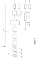
- FIG. 2 depicts a functional block diagram of the soil moisture and salinity sensor and its associated electronic sensor characteristic detection and transmission circuits.
- Capacitive (34, 36) and inductive (38, 40) elements in various combinations form an L-C tuning network for oscillator circuit 42.
- the senor comprises capacitive elements in the form of upper 34 and lower 36 conductive rings which, in use, arc disposed in longitudinally spaced relationship to each other to maintain a constant gap (which may be air but which can be calibrated to work with the existence of any intervening material) and located in the soil (or other medium to be measured) in a manner depicted in FIG. 1 .
- the rings are formed on a flexible substrate, which is configured to form rings of electrically conductive material, where the rings have different diameters or at least pairs of rings are of very similar diameter while pairs of rings forming a capacitive sensor are longitudinally spaced apart along the length of the housing having larger or smaller diameter depending on whether they are closer to the head end or inserted end of the housing.
- Figure 3 depicts an embodiment of the housing for a soil moisture sensor arrangement for use in a prepared opening in the soil, as depicted in Figure 1 .
- the housing has a body adapted for housing a soil moisture sensor arrangement.
- the adaption in one embodiment is such that an array of capacitive soil moisture sensors pre-mounted to a framework or printed circuit board will fit by having the body adapted to have a tapered inner wall shape that is shaped to accommodate the particular sensor array and may in one embodiment be adapted in shape in the vicinity of each capacitive sensor.
- a capacitive sensor includes two capacitive elements which are spaced longitudinally along the housing, the first capacitive element being spaced from the second capacitive element and the second being located closer to the inserted end than the first.
- capacitive sensors can be arrayed along the length of the inside of the body of the housing, spaced longitudinally along the housing from head end to the inserted end each individually associated with a tuned circuit.
- the body has a flexible form into which a flexible form of capacitive sensor is located.
- the flexible capacitive sensor is formed by conductive plastic material which can be folded or at least deformed to be placed into the housing via an open top region or in another embodiment passed through an aperture in the flexible form of the body and have some resilience and tendency to conform to the preferably rounded inner wall of the flexible body and when located appropriately along the internal length of the body ready to be connected as required with other capacitive sensors and an external communication arrangement, to permit the data collected or the data locally processed.
- an array of capacitive sensors is formed on a flexible carrier, such as a sheet of plastic or polyimide, and the sensor can be wrapped into a substantially circular cross-sectional that is also tapered so that one end has a larger diameter than the other end.
- the sheet on which the capacitive sensor is created is formed with at least one pair of opposite sides having non-parallel sides which can be housed within a housing of the form described herein because the shape of the sheet folds and fixes into a tapered form.
- a single sheet has the elements to provide for three sensors and an array of such sensors is created by aligning the sheets to have co-incident longitudinal axes while also providing for the increasing diameter of taper along the length of the housing.
- circular cross-section is exemplary only as the shape of the sensor need not be circular to perform its sensing task, although it is preferable that the sensor conform to the inner wall shape of the housing and that the outer wail shape is the same as the inner wall shape in cross-section so that the sensor is located so as to be in proximity to the soil in which the housing is inserted.
- the flexible sensor or sensor carrier is fed inside a housing and positioned adjacent the inner wall of the housing, which is substantially circular in cross-section.
- the inside of the housing can be filled with material so as to fix the sensors and other apparatus in location within the housing.
- the filling material will be electrically non-conducting and may contribute to the stiffening of the housing, for example, flowable polyurethane that solidifies to provide a high compressive strength and rigidity.
- the capacitive sensors can be arranged to be adjacent but spaced from the inner wall of the body of the housing such that the flowable material fully surrounds the sensor elements and arrangement of sensors and eventually solidifies about them to then fix their physical location with respect to the housing and also maintain their electromagnetic characteristics so that those characteristics are the same even after being transported, stored and installed. This is an important feature since the repeatability and longevity of the sensor array is greatly enhanced.
- the inside of the housing will thus contain appropriately positioned array/s of sensors, which are at the same time arranged to be connected with a respective capacitive sensor circuit and those circuits arc arranged to communicate their respective signals external of the housing (most preferably by wireless communications).
- the outer shape of the body is shaped for ease of insertion of the inserted end into a prepared opening 18 in the soil ( Figure 1 ) in that there is a generally a cone shape, in the case where the housing is generally circular in cross-section, as is pictorially depicted in Figure 3 .
- the housing were oblate or even square or rectangular in cross-section it would still be possible for the housing to accommodate an array of suitably shaped capacitive soil moisture sensor arrangements on a suitably shaped framework. It may also be that the body of the housing has these shapes along predetermined portions of its length.
- the internal wall/s of the housing would also be adapted to allow the capacitive elements to lie adjacent the inner wall when the framework is inserted into the housing, and further the external shape of the body of the housing is in conformance with the outer shape of the capacitive sensor, whatever its shape, so as to permit the capacitive elements of the sensor to lie close to the inner wall/s of the prepared opening in the soil and for conformance of the outer shape of the body with the soil forming the prepared opening so that the sensors are in proximity to the soil in which the housing is inserted.
- Proximity can be a matter of adjacency with no spacing, or within an electromagnetically acceptable spacing, taking the thickness of the housing and any other gap into consideration.
- One embodiment of such an arrangement may include a sheet of flexible material on which is located electrically conductive areas forming part of a tuned circuit wherein the sheet material has tabs deformable to project outward of the sheet toward the inner wall of the sensor housing and positioned about the sheet when formed to fit within the housing so as to centralize the sheet within the inner walls of the housing.
- the shape of the prepared opening in the soil needs to be complementary, in that the opening is also of a circular cross-section which tapers from the soil surface down to the lowest region of the opening.
- an auger with particular characteristics not normally found in augers.
- An auger 60 referring to Figure 4 , suitable for creating an opening with the characteristics described above, has in one embodiment a spiral flighting which has a larger outer circumference X at the driven end of the body of the auger than the outer circumference Y at the inserted end of the body of the auger of a 190 mm greater length of Z as is illustrated in Figure 4 .
- the driver of the rotation of the auger is by an electric drill of about 150 watts power capable of rotating the auger in a variety of soil types at least at 550 revolutions per minute. Those requirements are for guidance only and the user of the equipment will best judge the power requirements and efficiently conduct the drilling step of the process ensuring safety at the same time.
- a suitable auger dimension may depend on soil type and the complimentary housing shape and material it is made of.
- a particular form of an auger and method of manufacture is described in Australian Provisional patent application 20014901321 filed 10 April 2014 in the name of the present applicant.
- the arrangement may include a frame having a cylindrically shaped collar through which the auger is placed that provides a guide to the direction of the auger during the time it is operating, the frame being anchored to the ground is suitable manner.
- the method of installation of a capacitive soil moisture sensor arrangement when installed in a housing for use in a prepared opening in soil includes the steps of preparing an opening in the soil, where the opening has an inner wall formed when creating the opening such that the opening has a maximum inner diameter at the soil surface larger than the maximum inner diameter near the bottom of the opening below the surface of the soil so that substantially the full length of the housing is within the soil and the outer surface of the body of the housing is in contact with the inside wall of the prepared opening in the soil along substantially along the full length of the housing, indicating that the housing has been fully inserted into the prepared opening.
- the importance of fully inserting the housing come about because having the soil match the outside shape of the housing minimizes the potential for gaps and that minimizes or eliminates the air and water distortion to soil moisture and salinity measurements that are being recorded by the sensor array within the housing.
- the step of creating an aperture is best achieved using an auger of the description provided above but there might be other means and methods for achieving the form of an opening described.
- a preferred arrangement for preparing an opening it is sized to exceed the length of the housing so that the created extra hole space can accept soil that falls away from the auger during auger soil extraction without compromising the intended depth of the opening for full insertion of the sensor housing, such that the outer walls of the housing fit against the inner wall of the opening along the fully inserted length of the housing and where a depth of insertion datum line or indicator is used on the outer visible surface of the housing or the top of the housing is the datum then the full length of the encapsulated sensor within the housing lies within the prepared opening.
- the body of the housing is adapted to be inserted into the prepared opening such that the outer surface of the body is in conformance with the soil forming the prepared opening along the full length of the housing.
- the process of preparing an opening in the soil having an inner wall converging to the region near the base of the opening suitable for inserting the soil moisture sensor housing is achieved using an auger of the type described herein.
- the shape of the opening is determined by the outer shape of the auger but is arranged so that the opening is formed such that the outer surface of the body of the housing will be in contact with the soil sides of the prepared opening along the full length of the housing.
- the opening will generally have an inner wall converging to the region near the base of the opening.
- the preparation time and installation time is for those types of sensor housings in the order of 30 to 60 minutes as compared with less than 10 minutes for the sensor arrangement and housing disclosed in this specification, thus providing a great advantage to the installer (typically the crop grower) over the installation using prior arrangements, installation equipment and methods of installation.
- the next step of installation is inserting the body of the housing (as described above by way of numerous embodiments) and the sensor or sensor array located within the housing into the prepared opening and by forcing the outer walls of the housing are forced against the inner wall of the opening along the inserted length of the housing or most preferably along the full length of the housing.
- This step is possible when using a housing, which is of the form described above, wherein the head end of the housing has a maximum outer diameter larger than the maximum outer diameter of the inserted end of the housing
- a maximum outer diameter measurement criteria would equally apply if the cross-sectional shape of the housing was other than circular, so by way of example only, if the housing had an oblate cross-sectional shape along the longitudinal length of the housing, the maximum diameter can still be determined at both the head end and inserted end as well as at the surface and bottom of the prepared opening.
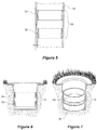
- FIG. 5 An embodiment of a capacitive soil moisture sensor element 14 for use within the housing is depicted in Figure 5 .
- the housing 18 is depicted having an exaggerated convergence of the inner wall of the housing, for an embodiment where the housing 18 has a circular cross-section and sensor elements 34 and 36 are formed from circular conductive rings.
- the exaggerated convergence of the housing wall possibly also exaggerates the divergence of the wall outwards from the top of each of the rings, but in practice the difference is very small and the outer wall of each ring will readily conform to the inner wall of the housing.
- Conform docs not necessarily mean touch but may include the form of the sensor element being evenly spaced from the inner wall.
- the exaggerated convergence is used to illustrate that the maximum outer diameter of each ring is slightly different, with the illustration showing that the upper ring in the figure (closer to the head end of the housing) has a slightly larger diameter than the lower ring in the figure (closer to the inserted end of the housing), whereas in practice the rings may have very closely matched diameters but still be different.
- the outer diameter of a ring is easily determined but the outer diameter of a sensor with a shape different from a ring can also be determined by measuring between the widest part of the sensor shape as seen from a side view of the shape when in use such that the nominal center of the shape is co-axial with the longitudinal axis of the longitudinal housing.
- the outer diameter of a capacitive sensor is the maximum of the diameters of the larger (if there is a difference) of the two capacitive elements that form the capacitive sensor.
- Figure 3 shows a partial perspective view of ring shaped capacitive sensors, arrayed in pairs along the length of the housing.
- the longitudinal axis of the housing is not shown but is the nominal central axis to the generally circular cross-sectional housing which as described earlier tapers in maximum outer diameter from x distance at the head end 50 to y distance at the inserted end 52.
- the longitudinal axis of the sensors will typically be co-axial with the minimal central axis of the housing when they are installed and eventually fixed in relation to the housing.
- rings in the depicted embodiment they will most likely be substantially the same and work together so as to provide a capacitive soil moisture sensor 34, 36 regardless of any minor difference in diameter when part of a tuned circuit, Much the same is also the case if the capacitive soil moisture sensor has other than a circular cross-sectional shape of metallic ring form, such as oblate or even rectangular or square, since in use in a tuned circuit those elements will still act to detect changes in the surrounding sphere of influence of the sensor and assist the determination of absolute values of moisture/complex dielectric constant and salinity in the adjacent soil.
- each capacitive sensor element is made of conductive material which can be flexible but located so as to conform with the inner wall shape of the housing, or located within a walled structure that with further processing becomes a sensor housing able to be inserted into a prepared opening in the soil.
- the additional capacitive soil moisture sensor element 14 thus forming an array of at least two capacitive soil moisture sensor elements for use in a tuned circuit and located within the housing as is pictorially shown in Figures 1 and 3 .
- the positioning of the capacitive soil moisture sensor elements can be used to obtain valuable information about the crop and its water uptake over time.
- Figure 6 depicts a cut-away view an example of a soil moisture sensor arrangement installed in the soil, which in this case is a turf environment where the depth at which measurement needs to take place is shallow soil, as compared to crop environments.
- this example of the housing still has the characteristics described above but the depth of the housing is much less that indicated is the case for the earlier described embodiment, being about 250 mm.
- the sensor elements and the housing have circular cross-sectional shape in the horizontal plane, when in use.
- Figure 7 depicts a cut-away perspective view of the example of a soil moisture sensor arrangement depicted in Figure 6 .
- the individual sensor elements 34 and 36 are show longitudinally spaced apart to create the capacitive component of the soil moisture determination circuit depicted, as one example of such a circuit, in Figure 2 .
- the figures are illustrative and there may be more than one sensor located in the housing and the dimensions of the sensors are exaggerated in the figures to ensure clarity.
- a post hole digger having a slightly convergent sidewall is used.
- the great advantage of this arrangement is that during insertion of the housing into the prepared opening, the convergent inner wall of the opening tends to be readily conformed to by the convergent outer wall of the housing to create little or no gaps between the sensor elements and the surrounding soil.
- the creation of the opening in the soil is appreciably simpler than prior methods and the shape of the housing conforms with the prepared opening to bring the capacitive soil moisture sensor elements close to the surrounding soil with the added benefit of minimization or elimination of air gaps and consequent water pooling between the housing and the surrounding soil.
- a reason to use a tapered sensor housing in a prepared tapered opening in the ground is the realization that the elimination of a gap is assured because the downward motion of the sensor into a complementary shaped opening ensure that the outer surface of the sensor housing will apply an pressure over the total outer area of the full inserted length of the sensor housing against the soil surface forming the opening. The greater the downward force on the sensor housing the greater the pressure and the greater likelihood that there will be no gaps between the outer surface area of the sensor housing and the soil surface forming the opening.
Landscapes
- Life Sciences & Earth Sciences (AREA)
- Chemical & Material Sciences (AREA)
- Health & Medical Sciences (AREA)
- Immunology (AREA)
- Pathology (AREA)
- Engineering & Computer Science (AREA)
- General Physics & Mathematics (AREA)
- General Health & Medical Sciences (AREA)
- Biochemistry (AREA)
- Analytical Chemistry (AREA)
- Physics & Mathematics (AREA)
- Medicinal Chemistry (AREA)
- Food Science & Technology (AREA)
- Environmental & Geological Engineering (AREA)
- General Life Sciences & Earth Sciences (AREA)
- Remote Sensing (AREA)
- Geology (AREA)
- Chemical Kinetics & Catalysis (AREA)
- Electrochemistry (AREA)
- Investigating Or Analyzing Materials By The Use Of Electric Means (AREA)
Description
- The field of the invention is soil sensors and in particular the sensor elements and sensor element housings and methods and apparatus for the placement of the soil sensor housing in the soil.
-
- Although the arrangements disclosed in the abovementioned patents are workable there are always pressures to minimize costs and create easier, more time saving and more simply repeatable arrangements for installing sensors in the soil and measuring the moisture and salinity of the soil.
- The invention disclosed herein provides one or more arrangements that are an improvement and/or alternative arrangement to those disclosed in the previously referred to patents and patent applications by the applicant.
-
US20060139037 discloses a device for measuring properties of soil having sensors mounted internally and circumferentially of a tapered probe tip located on the end of a rod. The rod provides a conduit for signals from the sensors (two electrode pairs) mounted within the tip and exposed to the soil. The signals from the electrodes are processed, and processed values are displayed, by circuits supported by the rod of the probe. The tip of the probe carrying the sensors is pushed into the soil to a depth chosen by the operator, and the sensors make their measurement. The probe can then be retracted and reused in another location. -
US4929885 discloses an apparatus for measuring the ground moisture content of the soil and comprises, in an embodiment, two electrodes forming a pair of rings which themselves serve as structural members of the probe. The rings are electrically conductive and are wired to form part of a capacitive sensor, and both rings are exposed to the soil. The probe in the vicinity of the structural sensor rings is tapered, as are the rings, thus one ring has a smaller diameter than the other ring. The tapered probe, in use, is inserted into an internally tapered opening in the soil so that at least along the exposed surface of the sensor rings, the exposed rings conform to the inner wall of the opening. The sensor housing above the structural pair of rings does not conform to the inner wall of the opening and the opening is backfilled to prevent moisture permeating the probe. - In one aspect of the invention there is a soil moisture sensor arrangement for use in a prepared opening in soil including: a housing including an elongate body with a head end, an inserted end, an inside wall, and an outer surface being continuously tapered from the head end to the inserted end; and a first and a second soil capacitive moisture sensor longitudinally spaced along the length of and located within the housing, the first and second capacitive moisture sensor comprising a first pair of rings and second pair of rings respectively, each ring of each pair made of electrically conductive material and of a similar size, the first pair of rings distal to the inserted end having a larger diameter than the second pair of rings proximal to the inserted end coinciding with the taper of the housing and wherein each ring of a sensor element is shaped to conform to the inside wall of the housing, and wherein each capacitive soil moisture sensor provides for the measurement of at least the moisture of the soil in which the sensor arrangement is inserted.
- In a further aspect of the invention a method for installing a capacitive soil moisture sensor arrangement in soil having a housing as described in the previous paragraph, includes the steps of:
- a) preparing an opening in the soil having an inner wall converging to the region near the base of the opening; and
- b) inserting the housing into the prepared opening until the outer surface of the body of the housing is in contact with the soil sides of the prepared opening along the full length of the housing.
- In a yet further aspect of the invention the capacitive sensor is substantially circular.
- In an embodiment of the invention a capacitive sensor includes at least two sensor elements of flexible conductive material.
- In an aspect of the invention the housing the body of the housing includes material that envelops multiple capacitive soil moisture sensor elements such that the sensor elements have a fixed location relative to the housing.
- In a further aspect of the invention the body of the housing of a soil moisture sensor arrangement includes a flexible form into which two or more flexible soil moisture sensor arrangements are located and further includes a material which is located inside the flexible form which stiffens the flexible form such that the body can be inserted into a prepared opening in the soil.
- In one aspect of the invention a depth datum is provided on an external portion of the body of housing to assist the insertion of the body into a prepared opening to a predetermined depth.
- In a further aspect the prepared opening is sized to exceed the length of the housing.
- In an aspect of the invention for use in the method of the invention described in at least the previous paragraph there is an auger used for preparing an opening suitable for the method of installation of the capacitive soil moisture sensor arrangement, the auger including, spiral flighting which has a larger outer circumference at the driven end of the body of the auger than the outer circumference at the inserted end of the body of the auger.
- The greater the downward force on the sensor housing the greater the pressure and the greater likelihood there will be no gaps between the outer area of the sensor housing and the soil surface forming the opening.
- Throughout this specification and the claims that follow unless the context requires otherwise, the words 'comprise' and 'include' and variations such as 'comprising' and 'including' will be understood to imply the inclusion of a stated integer or group of integers but not the exclusion of any other integer or group of integers.
- The reference to any background or prior art in this specification is not, and should not be taken as, an acknowledgment or any form of suggestion that such background or prior art forms part of the common general knowledge.
- Specific embodiments of the invention will now be described in some further detail with reference to and as illustrated in the accompanying figures. These embodiments are illustrative, and not meant to be restrictive of the scope of the invention. Suggestions and descriptions of other embodiments may be included within the scope of the invention but they may not be illustrated in the accompanying figures or alternatively features of the invention may be shown in the figures but not described in the specification.
-
-
Figure 1 depicts a cut-away view of an embodiment of a soil moisture sensor arrangement installed in the soil; -
Figure 2 depicts a schematic representation of part of a circuit of a soil moisture sensor arrangement; -
Figure 3 depicts a cut-away side view of two soil moisture sensors located in a housing; -
Figure 4 depicts a side view of an embodiment of an auger suitable for the creation of a suitable opening in the ground to accept the full length of the housing; -
Figure 5 depicts a close-up exploded side perspective view of two soil moisture sensor elements in a housing; -
Figure 6 depicts a cut-away side view of an example which is not the part of the present invention of soil moisture sensor elements installed in the soil; and -
Figure 7 depicts a cut-away perspective side view of the example of soil moisture sensor elements depicted inFigure 6 . - The need for a quick and effective installation method for soil moisture sensor is one of the reasons for the creation of the method and means of this invention.
- There are a number of aspects of the invention including in broad terms the following:
- a housing for a capacitive soil moisture sensor arrangement;
- an auger for forming an opening in soil suitable for the housing of a capacitive soil moisture sensor arrangement;
- an auger stabilization base plate and screw pins to stabilize the auger during drilling to assist in the creation of a soil opening having a consistent side wall for accepting the tapered shape of the sensor housing along its full length;
- an array of at least two a capacitive soil moisture sensors for use in the housing;
- a capacitive soil moisture sensor arrangement installed in a housing;
- a method for preparing an opening in the soil for the insertion of a housing for a capacitive soil moisture sensor arrangement; and
- a method of installation of a capacitive soil moisture sensor arrangement in a housing,
- The workings of a soil moisture and optionally a salinity sensor are adequately described in the reference patent applications in the name of the applicant as previously referred to, so that information will not be repeated herein, suffice to emphasize that there is a fundamental need for the sensor housing and hence the capacitive sensors within the housing to have in use, a conformance with the surrounding soil as can he achieved as a result of the design of the housing and sensor and the installation method used, for all those reasons espoused in the referenced patents.
- The capacitive sensor of this invention may be used as part of a measuring network including sensor circuitry which also reads multiple sensors which can temporarily store and/or transmit sensor data to an appropriate computer facility, data logger or hand held device.
- Additionally the raw data of the sensor may be processed using integrative models, that produce easily comprehensible trends and graphs, which aid the crop manager in making decisions related to management of irrigations and horticultural practices affecting crop production.
- The processes of collecting, storing, transmitting, calibrating, processing, and displaying data into critical values, pictures, graphs, trends, thresholds, tables, forecasts and recommendations to obtain an easy to use decision making tool for the purpose of irrigation scheduling are not described in detail in this specification.
-
FIG. 1 depicts an embodiment of a capacitive soilmoisture sensor arrangement 10, in situ, comprising asupport frame 12 for accommodating an array ofcapacitive sensors 14 located within ahousing 16 which has an open top end and a closed bottom end. The open top end can be scaled with a cap 17, although in an embodiment the sensor housing is sealed against environmental ingress, such as moisture in gaseous or liquid form by filling the housing with a flowable material which hardens and thus docs not have a separate top and all communication of data is wired or wireless. The housing is lowered into a preparedopening 18 in thesoil 20, which has asurface 22 until the whole of the length of the housing is within the soil. The internal diameter of thehousing 16 is shaped so as to allow the placement of thecapacitive sensors 14 in proximity of the inner wall of the housing and therefore adjacent to and close to the surrounding soil. - It has also been found to be preferable that the prepared opening in the ground is shaped so that the housing is a close fit to the surrounding soil so that the sensors that are placed therein are also close to the soil to be monitored. The presence of air gaps near the outer wall of the
housing 16 have been found to adversely affect the accuracy and repeatability as well as the absolute value of the measurements taken from the sensors in the vicinity of those gaps. Additionally the presence of air gaps can, upon the occurrence of a rain or irrigation event, allow a flow of water and possibly also the creation of pools of water that lie adjacent, during and after the rain or irrigation event, the sensor housing and hence the sensors, and the presence of that water adversely affects the accuracy and relevance of any measurements taken before, during, and after the rain event, particularly soil moisture and salinity measurements. - Any appreciable air gap may artificially reduce the density of the soil surrounding the access tube and may fill at times with water. In the first instance the air gap may distort the sphere of influence of the sensor and reduce the values of any measurements, in particular moisture and salinity measured and in the second instance water may distort and reduce the sphere of influence and of course may adversely affect the measured values
-
Capacitive sensors 14 are shown spaced longitudinally apart along asupport frame 12, which for the purpose of this embodiment are respectively at 10, 20, 30, ... centimeters below the surface of the soil (not shown in scale inFigure 1 but illustrated pictorially). During the course of the monitoring procedure thecapacitive sensors 14 remain in those positions. A datum indicator can be provided, in one form being a visible (embossed or raised shape) line around the outer of the body of the housing of the sensor arrangement positioned at a predetermined location along the length of the body. In another form the top of the housing can be the level to which the housing is inserted into the prepared opening. A datum indicator allows the reasonably accurate location of the capacitive sensors at the depths in the soil, indicated above, when the housing is inserted into the prepared opening, when the datum line is coincident with the soil surface. It can be noted that the soil surface is a known level readily determined in the field since it is the surface of the soil through which the crop will emerge and downwards of which the crop root system is located. The soil moisture, one embodiment, being measured by the sensor arrangement is intimately related with the development of the root system of the crop. - An
electronic circuit 24 is shown adjacent thecapacitive sensors 14 and is used to transduce changes in the characteristics of adjacent capacitive sensors the signals of which represent, in one embodiment, the moisture and optionally the salinity in the surroundingsoil 20 at predetermined time intervals and thus can be used to assess changes over time. - Preferably the
electronic circuit 24 is located adjacent its respective sensor upon thesupport frame 12, although in one embodiment the frame is in the form of a printed circuit board which is electrically attached to electrically conductive regions on a flexible substrate, which forms the capacitive elements of acapacitive sensor 14. The adjacency minimizes spurious signals being picked up on any interconnecting cables between the sensor and the circuit. Each electronic circuit includes the other required parts of a tuned circuit with which the capacitive elements interacts and that circuit is also adapted to provide a signal representative of, in one embodiment, the moisture and optionally the salinity and temperature of the surrounding soil that is then communicated to adata collection device 26 viamulti-stranded cable 28 or a printed circuit or another embodiment wirelessly from the sensor arrangement and external of the housing. In the embodiment depicted inFigure 1 , the location of a data collection device is adjacent to the insitu sensor apparatus 10 so that the effect of signal loss and spurious signal interference is minimized on the cable which is usable in such a configuration. However, it is not an ideal configuration since the physical space used takes away from the arable land available, it interrupts the tilling and tending of the crop in the immediate vicinity and adds another set of equipment that needs to be visited and maintained, hence in an embodiment not explicitly shown, the communication of data from the sensor array is via wireless means. In an embodiment the collected data is communicated external of the sensor housing using a wireless communication arrangement. In one preferred arrangement the data is communicated using Bluetooth™ to a mobile device, such as for example a Smart Phone on which an application is available to receive and process sensor data. The Bluetooth™ arrangement would likely be but not limited to being provided within the sensor housing. - Power for the sensor arrangement and the
data collection device 26 is provided from batteries (not shown) located adjacent the data logger, which are in turn charged by numerous power source options, solar-electric converter (solar panels) 30 and in other embodiment and electromagnetic contactless charger placed into proximity of the housing. - A
cap 32 is optionally located over the upper opening of thehousing 16 to assist the prevention of the ingress of rain, dirt and insects and thus protect the sensor apparatus from environmental damage. - The above configuration is but one example of a suitable capacitive soil moisture sensor arrangement.
- Another configuration not depicted in the figures, includes a fully environmentally encapsulated sensor arrangement, wherein the sensors arc positioned within a fully sealed body form and the data output uses an electrical cable or wireless signal, through which signaling representative of at least the collected soil moisture and salinity data, but which may also include, temperature, testing routine data, timing data, etc. while there is also a self-contained power supply within the sealed body form and if desired contacts which allow for wireless external charging of the power supply, such as for example a battery.
- There arc many forms in which a capacitive sensor can be created and installed into the body of the form described herein. In one form the sensors which make up an array of capacitive sensors is located within the housing fixed there relative to the housing when the housing is filled by a liquid which solidifies to not only fix the sensors into place but also provide rigidity to the housing.
-
FIG. 2 depicts a functional block diagram of the soil moisture and salinity sensor and its associated electronic sensor characteristic detection and transmission circuits. Capacitive (34, 36) and inductive (38, 40) elements in various combinations form an L-C tuning network foroscillator circuit 42. - In this embodiment the sensor comprises capacitive elements in the form of upper 34 and lower 36 conductive rings which, in use, arc disposed in longitudinally spaced relationship to each other to maintain a constant gap (which may be air but which can be calibrated to work with the existence of any intervening material) and located in the soil (or other medium to be measured) in a manner depicted in
FIG. 1 . - In an embodiment the rings are formed on a flexible substrate, which is configured to form rings of electrically conductive material, where the rings have different diameters or at least pairs of rings are of very similar diameter while pairs of rings forming a capacitive sensor are longitudinally spaced apart along the length of the housing having larger or smaller diameter depending on whether they are closer to the head end or inserted end of the housing.
- The remainder of the circuit depicted in
Figure 2 is described in detail inUS 5,418,466 and will not be described herein. This circuit is used by way of example only and is not the subject of this invention. -
Figure 3 depicts an embodiment of the housing for a soil moisture sensor arrangement for use in a prepared opening in the soil, as depicted inFigure 1 . - The housing has a body adapted for housing a soil moisture sensor arrangement. The adaption in one embodiment is such that an array of capacitive soil moisture sensors pre-mounted to a framework or printed circuit board will fit by having the body adapted to have a tapered inner wall shape that is shaped to accommodate the particular sensor array and may in one embodiment be adapted in shape in the vicinity of each capacitive sensor.
- A capacitive sensor includes two capacitive elements which are spaced longitudinally along the housing, the first capacitive element being spaced from the second capacitive element and the second being located closer to the inserted end than the first.
- Multiple of these capacitive sensors can be arrayed along the length of the inside of the body of the housing, spaced longitudinally along the housing from head end to the inserted end each individually associated with a tuned circuit.
- In an embodiment, the body has a flexible form into which a flexible form of capacitive sensor is located. The flexible capacitive sensor is formed by conductive plastic material which can be folded or at least deformed to be placed into the housing via an open top region or in another embodiment passed through an aperture in the flexible form of the body and have some resilience and tendency to conform to the preferably rounded inner wall of the flexible body and when located appropriately along the internal length of the body ready to be connected as required with other capacitive sensors and an external communication arrangement, to permit the data collected or the data locally processed.
- A particular form of a capacitive sensor is described in Australian Provisional patent application
20014901327 filed 10 April 2014 - The mention of circular cross-section is exemplary only as the shape of the sensor need not be circular to perform its sensing task, although it is preferable that the sensor conform to the inner wall shape of the housing and that the outer wail shape is the same as the inner wall shape in cross-section so that the sensor is located so as to be in proximity to the soil in which the housing is inserted.
- In yet another form, the flexible sensor or sensor carrier is fed inside a housing and positioned adjacent the inner wall of the housing, which is substantially circular in cross-section. The inside of the housing can be filled with material so as to fix the sensors and other apparatus in location within the housing. The filling material will be electrically non-conducting and may contribute to the stiffening of the housing, for example, flowable polyurethane that solidifies to provide a high compressive strength and rigidity.
- The capacitive sensors can be arranged to be adjacent but spaced from the inner wall of the body of the housing such that the flowable material fully surrounds the sensor elements and arrangement of sensors and eventually solidifies about them to then fix their physical location with respect to the housing and also maintain their electromagnetic characteristics so that those characteristics are the same even after being transported, stored and installed. This is an important feature since the repeatability and longevity of the sensor array is greatly enhanced.
- The inside of the housing will thus contain appropriately positioned array/s of sensors, which are at the same time arranged to be connected with a respective capacitive sensor circuit and those circuits arc arranged to communicate their respective signals external of the housing (most preferably by wireless communications).
- The body of the
housing 16 having ahead end 50 and an insertedend 52, the body shaped so that the maximum outer diameter of the inserted end is smaller than the maximum outer diameter of the head end of the body, in this embodiment x=30 mm and y= 24 mm and the length z of the housing is 1200 mm while inFigure 4 the length z of the auger is 190 mm longer than the z of the housing inFigure 3 . The outer shape of the body is shaped for ease of insertion of the inserted end into aprepared opening 18 in the soil (Figure 1 ) in that there is a generally a cone shape, in the case where the housing is generally circular in cross-section, as is pictorially depicted inFigure 3 . - However, if the housing were oblate or even square or rectangular in cross-section it would still be possible for the housing to accommodate an array of suitably shaped capacitive soil moisture sensor arrangements on a suitably shaped framework. It may also be that the body of the housing has these shapes along predetermined portions of its length. Furthermore the internal wall/s of the housing would also be adapted to allow the capacitive elements to lie adjacent the inner wall when the framework is inserted into the housing, and further the external shape of the body of the housing is in conformance with the outer shape of the capacitive sensor, whatever its shape, so as to permit the capacitive elements of the sensor to lie close to the inner wall/s of the prepared opening in the soil and for conformance of the outer shape of the body with the soil forming the prepared opening so that the sensors are in proximity to the soil in which the housing is inserted. Proximity can be a matter of adjacency with no spacing, or within an electromagnetically acceptable spacing, taking the thickness of the housing and any other gap into consideration. One embodiment of such an arrangement may include a sheet of flexible material on which is located electrically conductive areas forming part of a tuned circuit wherein the sheet material has tabs deformable to project outward of the sheet toward the inner wall of the sensor housing and positioned about the sheet when formed to fit within the housing so as to centralize the sheet within the inner walls of the housing.
- In an embodiment, where the housing has a circular cross-section which tapers from the
head end 50 down to the insertedend 52, the shape of the prepared opening in the soil needs to be complementary, in that the opening is also of a circular cross-section which tapers from the soil surface down to the lowest region of the opening. To create such an opening it is proposed to use an auger with particular characteristics not normally found in augers. - An
auger 60, referring toFigure 4 , suitable for creating an opening with the characteristics described above, has in one embodiment a spiral flighting which has a larger outer circumference X at the driven end of the body of the auger than the outer circumference Y at the inserted end of the body of the auger of a 190 mm greater length of Z as is illustrated inFigure 4 . The dimensions of the auger can be determined by knowing that the housing to be inserted into the prepared opening in the soil will be of a predetermined x, y and z dimension. In the case of a housing of the following dimension x=30, y=24 and z=1200 mm the auger dimension can be the same or slightly smaller, such as for example. x=29 mm, y= 23 mm at least at the 1200 mm depth z. - Most efficiently the driver of the rotation of the auger is by an electric drill of about 150 watts power capable of rotating the auger in a variety of soil types at least at 550 revolutions per minute. Those requirements are for guidance only and the user of the equipment will best judge the power requirements and efficiently conduct the drilling step of the process ensuring safety at the same time.
- A suitable auger dimension may depend on soil type and the complimentary housing shape and material it is made of. A particular form of an auger and method of manufacture is described in Australian Provisional patent application
20014901321 filed 10 April 2014 - It may be necessary to provide an arrangement (not shown) to stabilize the auger while it is being used to create the opening in the ground, wherein the arrangement directs the applied directly downward force to auger while it is rotating and minimizes any sideways forces during the excavation of soil from the ground. The arrangement may include a frame having a cylindrically shaped collar through which the auger is placed that provides a guide to the direction of the auger during the time it is operating, the frame being anchored to the ground is suitable manner.
- The method of installation of a capacitive soil moisture sensor arrangement according to any previous description when installed in a housing for use in a prepared opening in soil includes the steps of preparing an opening in the soil, where the opening has an inner wall formed when creating the opening such that the opening has a maximum inner diameter at the soil surface larger than the maximum inner diameter near the bottom of the opening below the surface of the soil so that substantially the full length of the housing is within the soil and the outer surface of the body of the housing is in contact with the inside wall of the prepared opening in the soil along substantially along the full length of the housing, indicating that the housing has been fully inserted into the prepared opening. The importance of fully inserting the housing come about because having the soil match the outside shape of the housing minimizes the potential for gaps and that minimizes or eliminates the air and water distortion to soil moisture and salinity measurements that are being recorded by the sensor array within the housing. The step of creating an aperture is best achieved using an auger of the description provided above but there might be other means and methods for achieving the form of an opening described.
- In a preferred arrangement for preparing an opening it is sized to exceed the length of the housing so that the created extra hole space can accept soil that falls away from the auger during auger soil extraction without compromising the intended depth of the opening for full insertion of the sensor housing, such that the outer walls of the housing fit against the inner wall of the opening along the fully inserted length of the housing and where a depth of insertion datum line or indicator is used on the outer visible surface of the housing or the top of the housing is the datum then the full length of the encapsulated sensor within the housing lies within the prepared opening.
- The body of the housing is adapted to be inserted into the prepared opening such that the outer surface of the body is in conformance with the soil forming the prepared opening along the full length of the housing.
- The process of preparing an opening in the soil having an inner wall converging to the region near the base of the opening suitable for inserting the soil moisture sensor housing is achieved using an auger of the type described herein. The shape of the opening is determined by the outer shape of the auger but is arranged so that the opening is formed such that the outer surface of the body of the housing will be in contact with the soil sides of the prepared opening along the full length of the housing. The opening will generally have an inner wall converging to the region near the base of the opening.
- It will be apparent to those used to preparing an opening for the soil moisture sensor arrangements disclosed in the referenced patents in this specification that the preparation time and installation time is for those types of sensor housings in the order of 30 to 60 minutes as compared with less than 10 minutes for the sensor arrangement and housing disclosed in this specification, thus providing a great advantage to the installer (typically the crop grower) over the installation using prior arrangements, installation equipment and methods of installation.
- The next step of installation is inserting the body of the housing (as described above by way of numerous embodiments) and the sensor or sensor array located within the housing into the prepared opening and by forcing the outer walls of the housing are forced against the inner wall of the opening along the inserted length of the housing or most preferably along the full length of the housing. This step is possible when using a housing, which is of the form described above, wherein the head end of the housing has a maximum outer diameter larger than the maximum outer diameter of the inserted end of the housing In particular, it is preferable for the outer wall/s of the housing to conform to the inner wall's of the prepared opening. A maximum outer diameter measurement criteria would equally apply if the cross-sectional shape of the housing was other than circular, so by way of example only, if the housing had an oblate cross-sectional shape along the longitudinal length of the housing, the maximum diameter can still be determined at both the head end and inserted end as well as at the surface and bottom of the prepared opening.
- An embodiment of a capacitive soil
moisture sensor element 14 for use within the housing is depicted inFigure 5 . Thehousing 18 is depicted having an exaggerated convergence of the inner wall of the housing, for an embodiment where thehousing 18 has a circular cross-section andsensor elements - Furthermore the exaggerated convergence is used to illustrate that the maximum outer diameter of each ring is slightly different, with the illustration showing that the upper ring in the figure (closer to the head end of the housing) has a slightly larger diameter than the lower ring in the figure (closer to the inserted end of the housing), whereas in practice the rings may have very closely matched diameters but still be different. The outer diameter of a ring is easily determined but the outer diameter of a sensor with a shape different from a ring can also be determined by measuring between the widest part of the sensor shape as seen from a side view of the shape when in use such that the nominal center of the shape is co-axial with the longitudinal axis of the longitudinal housing. The outer diameter of a capacitive sensor is the maximum of the diameters of the larger (if there is a difference) of the two capacitive elements that form the capacitive sensor.
-
Figure 3 shows a partial perspective view of ring shaped capacitive sensors, arrayed in pairs along the length of the housing. The longitudinal axis of the housing is not shown but is the nominal central axis to the generally circular cross-sectional housing which as described earlier tapers in maximum outer diameter from x distance at thehead end 50 to y distance at the insertedend 52. The longitudinal axis of the sensors will typically be co-axial with the minimal central axis of the housing when they are installed and eventually fixed in relation to the housing. - As for the electromagnetic characteristics of the shaped sensors, rings in the depicted embodiment, they will most likely be substantially the same and work together so as to provide a capacitive
soil moisture sensor - Not shown in
Figure 5 is the additional capacitive soilmoisture sensor element 14 thus forming an array of at least two capacitive soil moisture sensor elements for use in a tuned circuit and located within the housing as is pictorially shown inFigures 1 and3 . In practical arrangements there will be pairs of capacitive soilmoisture sensor elements 14 longitudinally spaced about 10 centimeters apart, along the full depth/length or part of the depth/length of the housing, or there may be, depending on the crop in the surrounding soil, clusters of capacitive soilmoisture sensor elements 14 located along the depth of the housing. As disclosed in the referenced patents in the name of the applicant the positioning of the capacitive soil moisture sensor elements can be used to obtain valuable information about the crop and its water uptake over time. -
Figure 6 depicts a cut-away view an example of a soil moisture sensor arrangement installed in the soil, which in this case is a turf environment where the depth at which measurement needs to take place is shallow soil, as compared to crop environments. In the views provided inFigures 6 and 7 this example of the housing still has the characteristics described above but the depth of the housing is much less that indicated is the case for the earlier described embodiment, being about 250 mm. In this example the sensor elements and the housing have circular cross-sectional shape in the horizontal plane, when in use. -
Figure 7 depicts a cut-away perspective view of the example of a soil moisture sensor arrangement depicted inFigure 6 . As is the case in bothFigures 6 and 7 theindividual sensor elements Figure 2 . The figures are illustrative and there may be more than one sensor located in the housing and the dimensions of the sensors are exaggerated in the figures to ensure clarity. - To create the opening in the soil (turf base material) a post hole digger having a slightly convergent sidewall is used. The great advantage of this arrangement is that during insertion of the housing into the prepared opening, the convergent inner wall of the opening tends to be readily conformed to by the convergent outer wall of the housing to create little or no gaps between the sensor elements and the surrounding soil.
- In relation to all of the embodiments disclosed in this specification the creation of the opening in the soil is appreciably simpler than prior methods and the shape of the housing conforms with the prepared opening to bring the capacitive soil moisture sensor elements close to the surrounding soil with the added benefit of minimization or elimination of air gaps and consequent water pooling between the housing and the surrounding soil.
- A reason to use a tapered sensor housing in a prepared tapered opening in the ground is the realization that the elimination of a gap is assured because the downward motion of the sensor into a complementary shaped opening ensure that the outer surface of the sensor housing will apply an pressure over the total outer area of the full inserted length of the sensor housing against the soil surface forming the opening. The greater the downward force on the sensor housing the greater the pressure and the greater likelihood that there will be no gaps between the outer surface area of the sensor housing and the soil surface forming the opening.
- Thus there is a reason to provide a sensor array that also conforms in shape and arrangement to the inside wall of the housing which also includes smaller diameter rings for each pair of capacitive elements as they are located further down (with respect to the head end of the sensor housing) the elongate sensor housing.
- It will be appreciated by those skilled in the art that the invention is not restricted in its use to the particular application described. Neither is the present invention restricted in its preferred embodiment with regard to the particular elements and/or features described or depicted herein. It will be appreciated that various modifications can be made without departing from the principles of the invention. Therefore, the invention should be understood to include all such modifications within its scope.
Claims (9)
- A soil moisture sensor arrangement for use in a prepared opening (18) in soil including:a housing (16) including an elongate body with a head end (50), an inserted end (52), an inside wall, and an outer surface being continuously tapered from the head end to the inserted end; anda first and a second capacitive soil moisture sensor (14) longitudinally spaced along the length of and located within the housing, the first and second capacitive moisture sensor comprising a first pair of rings and second pair of rings respectively, each ring of each pair made of electrically conductive material and of a similar size, the first pair of rings distal to the inserted end (52) having a larger diameter than the second pair of rings proximal to the inserted end (52) coinciding with the taper of the housing (16) and wherein each ring of a sensor element is shaped to conform to the inside wall of the housing, and wherein each capacitive soil moisture sensor provides for the measurement of at least the moisture of the soil in which the sensor arrangement is inserted.
- A soil moisture sensor arrangement according to claim 1 wherein the housing has a circular cross-sectional shape and each capacitive sensor is substantially circular.
- A soil moisture sensor arrangement according to claims 1 or 2 wherein each capacitive sensor includes a sensor element of flexible conductive material.
- soil moisture sensor arrangement according to claims 1 or 2 or 3 wherein the inner wall shape of the housing is tapered to accommodate the capacitive soil moisture sensors having larger or smaller diameter depending on whether they are closer to the head end or inserted end of the housing.
- A soil moisture sensor arrangement according to claims 1 or 2 or 3 or 4 wherein the body of the housing includes material that envelops multiple capacitive soil moisture sensor elements such that the sensor elements have a fixed location relative to the housing.
- A soil moisture sensor arrangement according to claims 1 or 2 or 3 or 4 or 5 wherein the body of the housing of a soil moisture sensor arrangement includes a flexible form into which two or more soil moisture sensor elements are located and further includes a material which is located inside the flexible form which stiffens the flexible form such that the body can be inserted into a prepared opening in the soil.
- A soil moisture sensor arrangement according to claims 1 or 2 or 3 or 4 or 5 or 6 wherein the body of the housing includes a depth datum provided on an external portion of the body of the housing to assist the insertion of the body into a prepared opening to a predetermined depth.
- A soil moisture sensor arrangement according to claims 1 or 2 or 3 or 4 or 5 or 6 or 7 wherein the head end has an outer diameter of 30 mm and the inserted end has an outer diameter of 24 mm and the length of the housing is 1200 mm.
- A method for installing a soil moisture sensor arrangement according to claim 1 in soil, the method includes the steps of:a) preparing an opening in the soil having an inner wall converging to the region near the base of the opening; andb) inserting the housing into the prepared opening until the outer surface of the body of the housing is in contact with the soil sides of the prepared opening along the full length of the housing.
Applications Claiming Priority (2)
| Application Number | Priority Date | Filing Date | Title |
|---|---|---|---|
| AU2013901224A AU2013901224A0 (en) | 2013-04-10 | Conical soil moisture sensor arrangement and method of installation | |
| PCT/AU2014/000383 WO2014165910A1 (en) | 2013-04-10 | 2014-04-10 | Tapered soil moisture sensor arrangement and method of installation |
Publications (3)
| Publication Number | Publication Date |
|---|---|
| EP2984475A1 EP2984475A1 (en) | 2016-02-17 |
| EP2984475A4 EP2984475A4 (en) | 2016-11-16 |
| EP2984475B1 true EP2984475B1 (en) | 2021-02-17 |
Family
ID=51688727
Family Applications (1)
| Application Number | Title | Priority Date | Filing Date |
|---|---|---|---|
| EP14782129.2A Active EP2984475B1 (en) | 2013-04-10 | 2014-04-10 | Tapered soil moisture sensor arrangement and method of installation |
Country Status (6)
| Country | Link |
|---|---|
| US (1) | US10060873B2 (en) |
| EP (1) | EP2984475B1 (en) |
| CN (1) | CN105492897A (en) |
| AU (1) | AU2014252762B2 (en) |
| ES (1) | ES2866626T3 (en) |
| WO (1) | WO2014165910A1 (en) |
Families Citing this family (24)
| Publication number | Priority date | Publication date | Assignee | Title |
|---|---|---|---|---|
| AU2015245932A1 (en) | 2014-04-10 | 2016-10-27 | Sentek Pty Ltd | Soil auger and method of manufacture |
| WO2015154129A1 (en) * | 2014-04-10 | 2015-10-15 | Sentek Pty Ltd. | Flexible sensor circuit arrangement |
| US20170118930A1 (en) * | 2015-10-30 | 2017-05-04 | Telsco Industries, Inc. d/b/a Weathermatic | Systems and Methods for Sensing Precipitation |
| US10935537B2 (en) * | 2015-11-25 | 2021-03-02 | AquaSpy, Inc. | Soil moisture and electrical conductivity probe |
| CN109154590A (en) * | 2015-12-03 | 2019-01-04 | 克罗普克斯技术有限公司 | Soil sensor component |
| WO2018068079A1 (en) | 2016-10-13 | 2018-04-19 | University Of South Australia | Apparatus and method for anion detection and/or measurement |
| US10197378B2 (en) * | 2016-10-27 | 2019-02-05 | Deere & Company | Time domain depth sensor |
| NL1042193B1 (en) * | 2016-12-23 | 2018-07-02 | Sensoterra | Measuring probe for measuring in ground a parameter and a method for making such a probe |
| US10444176B2 (en) * | 2017-02-17 | 2019-10-15 | Deere & Company | Sensing system for measuring soil properties in real time |
| RU186702U1 (en) * | 2017-08-08 | 2019-01-30 | Анатолий Иванович Прокопьев | CAPACITIVE SOIL MOISTURE SENSOR |
| US11985925B2 (en) | 2017-08-22 | 2024-05-21 | Sentek Pty Ltd. | Method of determination of water stress in a one or more plants in a crop located in the region of a soil moisture sensor array and knowledge of ETo |
| WO2019036744A1 (en) | 2017-08-22 | 2019-02-28 | Sentek Pty Ltd | Method of determination of water stress in a one or more plants in a crop located in the vicinity of a soil moisture sensor array and knowledge of eto |
| DE102017008305A1 (en) * | 2017-09-01 | 2019-03-07 | viRaTec GmbH | Method for arranging a soil moisture measuring device in a measuring position for measuring the moisture of a soil |
| US20190159412A1 (en) * | 2017-11-29 | 2019-05-30 | Jerome GUIDISH | In-ground moisture sensor and system |
| EP3875918A1 (en) * | 2020-03-02 | 2021-09-08 | Husqvarna Ab | Transmitter device |
| EP3875954A1 (en) | 2020-03-02 | 2021-09-08 | Husqvarna Ab | Transmitter device |
| DE102020001799A1 (en) | 2020-03-18 | 2021-09-23 | Agvolution GmbH i. Gr. | Device for determining data on a floor area and method for querying data by means of an application |
| WO2022165057A1 (en) * | 2021-01-29 | 2022-08-04 | The Regents Of The University Of Colorado, A Body Corporate | Additively fabricated capacitive soil moisture sensor |
| CN113295844A (en) * | 2021-04-13 | 2021-08-24 | 广东白云学院 | Agricultural product quality safety monitoring equipment based on Internet of things |
| CN114216388B (en) * | 2021-11-26 | 2022-08-16 | 中南大学 | Displacement correction method for dual-path nano sensor |
| CN114594071A (en) * | 2022-03-30 | 2022-06-07 | 西安交通大学 | A soil moisture fiber grating detection sensor |
| ES2976090A1 (en) | 2022-12-01 | 2024-07-23 | Lluch Antonio Martinez | Humidity and temperature measurement equipment inside the walls and the space where the measurement equipment is housed (Machine-translation by Google Translate, not legally binding) |
| EP4680943A1 (en) * | 2023-03-17 | 2026-01-21 | Sentek Pty Ltd. | Analyte in soil and other medium sensor arrangement |
| WO2025032382A1 (en) * | 2023-08-09 | 2025-02-13 | Precision Planting Llc | Below ground sensing system for sensing different soil parameters |
Family Cites Families (15)
| Publication number | Priority date | Publication date | Assignee | Title |
|---|---|---|---|---|
| US4929885A (en) * | 1988-11-08 | 1990-05-29 | Troxler Electronic Laboratories, Inc. | Apparatus for measuring ground moisture content of soil |
| US5418466A (en) * | 1990-10-12 | 1995-05-23 | Watson; Keith | Moisture and salinity sensor and method of use |
| US5260666A (en) * | 1991-09-23 | 1993-11-09 | Troxler Electronic Laboratories, Inc. | Capacitance monitor for soil moisture |
| US5224769A (en) | 1992-01-03 | 1993-07-06 | University Of Florida | Method and device for non-invasive monitoring of hydration state of plants |
| AU760525B2 (en) | 1998-07-21 | 2003-05-15 | Sentek Pty Ltd | Automatic depth sensing detection for portable soil moisture probes |
| EP1736771A3 (en) | 2000-07-13 | 2007-03-21 | National Research Institute For Earth Science And Disaster Prevention | Elektrode rod for measuring conductivity or resistivity |
| CN2470823Y (en) * | 2001-04-13 | 2002-01-09 | 单元道 | Plug-in type sensor of capacitor type water-content detecting instrument |
| AU2002331464B2 (en) | 2001-10-05 | 2007-06-28 | Sentek Pty Ltd. | Soil probe insertion arrangement and method of use |
| AUPR807801A0 (en) | 2001-10-05 | 2001-10-25 | Sentek Pty Ltd | Soil probe insertion arrangement and method of use |
| US6906530B2 (en) * | 2002-05-30 | 2005-06-14 | D.J. Geisel Technology, Inc. | Apparatus and method to detect moisture |
| AU2002953346A0 (en) | 2002-12-16 | 2003-01-09 | Sentek Pty Ltd | Soil matric potential and salinity measurement apparatus and method of use |
| US7183779B2 (en) * | 2004-12-28 | 2007-02-27 | Spectrum Technologies, Inc. | Soil probe device and method of making same |
| CN2854589Y (en) * | 2005-03-16 | 2007-01-03 | 中国农业大学 | Analysing sensor for soil moisture |
| US7170302B2 (en) * | 2005-06-27 | 2007-01-30 | Fu Ching Lee | Capacitive soil moisture sensor |
| CN102297883A (en) * | 2011-05-20 | 2011-12-28 | 江苏大学 | Water content detection apparatus for soil profile, and detection method thereof |
-
2014
- 2014-04-10 CN CN201480020561.6A patent/CN105492897A/en active Pending
- 2014-04-10 US US14/782,626 patent/US10060873B2/en active Active
- 2014-04-10 AU AU2014252762A patent/AU2014252762B2/en active Active
- 2014-04-10 WO PCT/AU2014/000383 patent/WO2014165910A1/en not_active Ceased
- 2014-04-10 ES ES14782129T patent/ES2866626T3/en active Active
- 2014-04-10 EP EP14782129.2A patent/EP2984475B1/en active Active
Non-Patent Citations (1)
| Title |
|---|
| None * |
Also Published As
| Publication number | Publication date |
|---|---|
| EP2984475A1 (en) | 2016-02-17 |
| WO2014165910A1 (en) | 2014-10-16 |
| ES2866626T3 (en) | 2021-10-19 |
| US20160061762A1 (en) | 2016-03-03 |
| US10060873B2 (en) | 2018-08-28 |
| AU2014252762B2 (en) | 2018-07-12 |
| EP2984475A4 (en) | 2016-11-16 |
| CN105492897A (en) | 2016-04-13 |
| AU2014252762A1 (en) | 2015-10-15 |
Similar Documents
| Publication | Publication Date | Title |
|---|---|---|
| US10060873B2 (en) | Tapered soil moisture sensor arrangement and method of installation | |
| EP2883445B1 (en) | Extendable wireless soil measurement apparatus | |
| US8643387B2 (en) | Moisture sensor | |
| CA3084116A1 (en) | Moisture soil probe system and method | |
| CN107701170B (en) | Near-bit imaging measurement device and method | |
| CN108684221B (en) | Gardening device and method for sowing or planting by means of said gardening device | |
| CN103266887B (en) | A kind of instrument by the dark resistivity of wireless short pass signal measurement and using method thereof | |
| CN105256786B (en) | Cable-free static sounding equipment and using method thereof | |
| US20150204041A1 (en) | Two-tier wireless soil measurement apparatus | |
| US12449399B2 (en) | Method and system for determining surface level and soil infiltration under irrigation | |
| US10359384B2 (en) | Flexible sensor circuit arrangement | |
| CN215217888U (en) | System for monitoring pressure of ice layer section in middle of river reservoir | |
| CN107438697A (en) | For providing the stabilizer with fin installing type electrode of signal to drill string antenna | |
| JP2012088144A (en) | Landslide observation system | |
| CN101975802B (en) | Embedded soil moisture content sensor and application thereof | |
| CN211013084U (en) | Soil temperature and humidity detection system | |
| WO2017132287A1 (en) | Downhole tension sensing apparatus | |
| CN208847730U (en) | Hillside fields water and soil conservation value device | |
| CN113027437B (en) | Method and device for realizing resistivity measurement based on logging while drilling instrument | |
| CN205300701U (en) | Ground water level measuring tape | |
| CN204690724U (en) | Become the device that vacuum pressure measured by dielectric cylinder shape capacitor | |
| CN114485512B (en) | Deep displacement monitoring equipment for wireless signal transmission and error testing method | |
| CN112987109A (en) | Multifunctional portable cross-hole resistivity CT signal acquisition device, system and method | |
| RU2004107289A (en) | METHOD FOR MEASURING PRESSURE AND TRANSFER OF DATA IN AN OPERATIONAL WELL AND A DEVICE FOR ITS IMPLEMENTATION | |
| CN206071192U (en) | A kind of concrete wire pole with the inclined function of survey |
Legal Events
| Date | Code | Title | Description |
|---|---|---|---|
| PUAI | Public reference made under article 153(3) epc to a published international application that has entered the european phase |
Free format text: ORIGINAL CODE: 0009012 |
|
| 17P | Request for examination filed |
Effective date: 20151001 |
|
| AK | Designated contracting states |
Kind code of ref document: A1 Designated state(s): AL AT BE BG CH CY CZ DE DK EE ES FI FR GB GR HR HU IE IS IT LI LT LU LV MC MK MT NL NO PL PT RO RS SE SI SK SM TR |
|
| AX | Request for extension of the european patent |
Extension state: BA ME |
|
| DAX | Request for extension of the european patent (deleted) | ||
| A4 | Supplementary search report drawn up and despatched |
Effective date: 20161017 |
|
| RIC1 | Information provided on ipc code assigned before grant |
Ipc: G01N 27/22 20060101AFI20161011BHEP |
|
| STAA | Information on the status of an ep patent application or granted ep patent |
Free format text: STATUS: EXAMINATION IS IN PROGRESS |
|
| 17Q | First examination report despatched |
Effective date: 20180419 |
|
| GRAP | Despatch of communication of intention to grant a patent |
Free format text: ORIGINAL CODE: EPIDOSNIGR1 |
|
| STAA | Information on the status of an ep patent application or granted ep patent |
Free format text: STATUS: GRANT OF PATENT IS INTENDED |
|
| INTG | Intention to grant announced |
Effective date: 20200827 |
|
| GRAS | Grant fee paid |
Free format text: ORIGINAL CODE: EPIDOSNIGR3 |
|
| GRAA | (expected) grant |
Free format text: ORIGINAL CODE: 0009210 |
|
| STAA | Information on the status of an ep patent application or granted ep patent |
Free format text: STATUS: THE PATENT HAS BEEN GRANTED |
|
| AK | Designated contracting states |
Kind code of ref document: B1 Designated state(s): AL AT BE BG CH CY CZ DE DK EE ES FI FR GB GR HR HU IE IS IT LI LT LU LV MC MK MT NL NO PL PT RO RS SE SI SK SM TR |
|
| REG | Reference to a national code |
Ref country code: GB Ref legal event code: FG4D |
|
| REG | Reference to a national code |
Ref country code: CH Ref legal event code: EP |
|
| REG | Reference to a national code |
Ref country code: DE Ref legal event code: R096 Ref document number: 602014074873 Country of ref document: DE |
|
| REG | Reference to a national code |
Ref country code: AT Ref legal event code: REF Ref document number: 1362101 Country of ref document: AT Kind code of ref document: T Effective date: 20210315 |
|
| REG | Reference to a national code |
Ref country code: IE Ref legal event code: FG4D |
|
| REG | Reference to a national code |
Ref country code: LT Ref legal event code: MG9D |
|
| REG | Reference to a national code |
Ref country code: NL Ref legal event code: MP Effective date: 20210217 |
|
| PG25 | Lapsed in a contracting state [announced via postgrant information from national office to epo] |
Ref country code: PT Free format text: LAPSE BECAUSE OF FAILURE TO SUBMIT A TRANSLATION OF THE DESCRIPTION OR TO PAY THE FEE WITHIN THE PRESCRIBED TIME-LIMIT Effective date: 20210617 Ref country code: LT Free format text: LAPSE BECAUSE OF FAILURE TO SUBMIT A TRANSLATION OF THE DESCRIPTION OR TO PAY THE FEE WITHIN THE PRESCRIBED TIME-LIMIT Effective date: 20210217 Ref country code: GR Free format text: LAPSE BECAUSE OF FAILURE TO SUBMIT A TRANSLATION OF THE DESCRIPTION OR TO PAY THE FEE WITHIN THE PRESCRIBED TIME-LIMIT Effective date: 20210518 Ref country code: FI Free format text: LAPSE BECAUSE OF FAILURE TO SUBMIT A TRANSLATION OF THE DESCRIPTION OR TO PAY THE FEE WITHIN THE PRESCRIBED TIME-LIMIT Effective date: 20210217 Ref country code: HR Free format text: LAPSE BECAUSE OF FAILURE TO SUBMIT A TRANSLATION OF THE DESCRIPTION OR TO PAY THE FEE WITHIN THE PRESCRIBED TIME-LIMIT Effective date: 20210217 Ref country code: BG Free format text: LAPSE BECAUSE OF FAILURE TO SUBMIT A TRANSLATION OF THE DESCRIPTION OR TO PAY THE FEE WITHIN THE PRESCRIBED TIME-LIMIT Effective date: 20210517 Ref country code: NO Free format text: LAPSE BECAUSE OF FAILURE TO SUBMIT A TRANSLATION OF THE DESCRIPTION OR TO PAY THE FEE WITHIN THE PRESCRIBED TIME-LIMIT Effective date: 20210517 |
|
| REG | Reference to a national code |
Ref country code: AT Ref legal event code: MK05 Ref document number: 1362101 Country of ref document: AT Kind code of ref document: T Effective date: 20210217 |
|
| PG25 | Lapsed in a contracting state [announced via postgrant information from national office to epo] |
Ref country code: RS Free format text: LAPSE BECAUSE OF FAILURE TO SUBMIT A TRANSLATION OF THE DESCRIPTION OR TO PAY THE FEE WITHIN THE PRESCRIBED TIME-LIMIT Effective date: 20210217 Ref country code: LV Free format text: LAPSE BECAUSE OF FAILURE TO SUBMIT A TRANSLATION OF THE DESCRIPTION OR TO PAY THE FEE WITHIN THE PRESCRIBED TIME-LIMIT Effective date: 20210217 Ref country code: NL Free format text: LAPSE BECAUSE OF FAILURE TO SUBMIT A TRANSLATION OF THE DESCRIPTION OR TO PAY THE FEE WITHIN THE PRESCRIBED TIME-LIMIT Effective date: 20210217 Ref country code: PL Free format text: LAPSE BECAUSE OF FAILURE TO SUBMIT A TRANSLATION OF THE DESCRIPTION OR TO PAY THE FEE WITHIN THE PRESCRIBED TIME-LIMIT Effective date: 20210217 Ref country code: SE Free format text: LAPSE BECAUSE OF FAILURE TO SUBMIT A TRANSLATION OF THE DESCRIPTION OR TO PAY THE FEE WITHIN THE PRESCRIBED TIME-LIMIT Effective date: 20210217 |
|
| PG25 | Lapsed in a contracting state [announced via postgrant information from national office to epo] |
Ref country code: IS Free format text: LAPSE BECAUSE OF FAILURE TO SUBMIT A TRANSLATION OF THE DESCRIPTION OR TO PAY THE FEE WITHIN THE PRESCRIBED TIME-LIMIT Effective date: 20210617 |
|
| REG | Reference to a national code |
Ref country code: ES Ref legal event code: FG2A Ref document number: 2866626 Country of ref document: ES Kind code of ref document: T3 Effective date: 20211019 |
|
| PG25 | Lapsed in a contracting state [announced via postgrant information from national office to epo] |
Ref country code: CZ Free format text: LAPSE BECAUSE OF FAILURE TO SUBMIT A TRANSLATION OF THE DESCRIPTION OR TO PAY THE FEE WITHIN THE PRESCRIBED TIME-LIMIT Effective date: 20210217 Ref country code: EE Free format text: LAPSE BECAUSE OF FAILURE TO SUBMIT A TRANSLATION OF THE DESCRIPTION OR TO PAY THE FEE WITHIN THE PRESCRIBED TIME-LIMIT Effective date: 20210217 Ref country code: AT Free format text: LAPSE BECAUSE OF FAILURE TO SUBMIT A TRANSLATION OF THE DESCRIPTION OR TO PAY THE FEE WITHIN THE PRESCRIBED TIME-LIMIT Effective date: 20210217 Ref country code: SM Free format text: LAPSE BECAUSE OF FAILURE TO SUBMIT A TRANSLATION OF THE DESCRIPTION OR TO PAY THE FEE WITHIN THE PRESCRIBED TIME-LIMIT Effective date: 20210217 |
|
| REG | Reference to a national code |
Ref country code: DE Ref legal event code: R097 Ref document number: 602014074873 Country of ref document: DE |
|
| PG25 | Lapsed in a contracting state [announced via postgrant information from national office to epo] |
Ref country code: SK Free format text: LAPSE BECAUSE OF FAILURE TO SUBMIT A TRANSLATION OF THE DESCRIPTION OR TO PAY THE FEE WITHIN THE PRESCRIBED TIME-LIMIT Effective date: 20210217 Ref country code: RO Free format text: LAPSE BECAUSE OF FAILURE TO SUBMIT A TRANSLATION OF THE DESCRIPTION OR TO PAY THE FEE WITHIN THE PRESCRIBED TIME-LIMIT Effective date: 20210217 Ref country code: DK Free format text: LAPSE BECAUSE OF FAILURE TO SUBMIT A TRANSLATION OF THE DESCRIPTION OR TO PAY THE FEE WITHIN THE PRESCRIBED TIME-LIMIT Effective date: 20210217 Ref country code: MC Free format text: LAPSE BECAUSE OF FAILURE TO SUBMIT A TRANSLATION OF THE DESCRIPTION OR TO PAY THE FEE WITHIN THE PRESCRIBED TIME-LIMIT Effective date: 20210217 |
|
| PLBE | No opposition filed within time limit |
Free format text: ORIGINAL CODE: 0009261 |
|
| STAA | Information on the status of an ep patent application or granted ep patent |
Free format text: STATUS: NO OPPOSITION FILED WITHIN TIME LIMIT |
|
| PG25 | Lapsed in a contracting state [announced via postgrant information from national office to epo] |
Ref country code: LU Free format text: LAPSE BECAUSE OF NON-PAYMENT OF DUE FEES Effective date: 20210410 |
|
| REG | Reference to a national code |
Ref country code: BE Ref legal event code: MM Effective date: 20210430 |
|
| 26N | No opposition filed |
Effective date: 20211118 |
|
| PG25 | Lapsed in a contracting state [announced via postgrant information from national office to epo] |
Ref country code: CH Free format text: LAPSE BECAUSE OF NON-PAYMENT OF DUE FEES Effective date: 20210430 Ref country code: AL Free format text: LAPSE BECAUSE OF FAILURE TO SUBMIT A TRANSLATION OF THE DESCRIPTION OR TO PAY THE FEE WITHIN THE PRESCRIBED TIME-LIMIT Effective date: 20210217 Ref country code: LI Free format text: LAPSE BECAUSE OF NON-PAYMENT OF DUE FEES Effective date: 20210430 |
|
| PG25 | Lapsed in a contracting state [announced via postgrant information from national office to epo] |
Ref country code: SI Free format text: LAPSE BECAUSE OF FAILURE TO SUBMIT A TRANSLATION OF THE DESCRIPTION OR TO PAY THE FEE WITHIN THE PRESCRIBED TIME-LIMIT Effective date: 20210217 |
|
| PG25 | Lapsed in a contracting state [announced via postgrant information from national office to epo] |
Ref country code: IE Free format text: LAPSE BECAUSE OF NON-PAYMENT OF DUE FEES Effective date: 20210410 |
|
| PG25 | Lapsed in a contracting state [announced via postgrant information from national office to epo] |
Ref country code: IS Free format text: LAPSE BECAUSE OF FAILURE TO SUBMIT A TRANSLATION OF THE DESCRIPTION OR TO PAY THE FEE WITHIN THE PRESCRIBED TIME-LIMIT Effective date: 20210617 |
|
| PG25 | Lapsed in a contracting state [announced via postgrant information from national office to epo] |
Ref country code: BE Free format text: LAPSE BECAUSE OF NON-PAYMENT OF DUE FEES Effective date: 20210430 |
|
| PG25 | Lapsed in a contracting state [announced via postgrant information from national office to epo] |
Ref country code: HU Free format text: LAPSE BECAUSE OF FAILURE TO SUBMIT A TRANSLATION OF THE DESCRIPTION OR TO PAY THE FEE WITHIN THE PRESCRIBED TIME-LIMIT; INVALID AB INITIO Effective date: 20140410 |
|
| PG25 | Lapsed in a contracting state [announced via postgrant information from national office to epo] |
Ref country code: CY Free format text: LAPSE BECAUSE OF FAILURE TO SUBMIT A TRANSLATION OF THE DESCRIPTION OR TO PAY THE FEE WITHIN THE PRESCRIBED TIME-LIMIT Effective date: 20210217 |
|
| P01 | Opt-out of the competence of the unified patent court (upc) registered |
Effective date: 20230628 |
|
| PG25 | Lapsed in a contracting state [announced via postgrant information from national office to epo] |
Ref country code: MK Free format text: LAPSE BECAUSE OF FAILURE TO SUBMIT A TRANSLATION OF THE DESCRIPTION OR TO PAY THE FEE WITHIN THE PRESCRIBED TIME-LIMIT Effective date: 20210217 |
|
| PG25 | Lapsed in a contracting state [announced via postgrant information from national office to epo] |
Ref country code: MT Free format text: LAPSE BECAUSE OF FAILURE TO SUBMIT A TRANSLATION OF THE DESCRIPTION OR TO PAY THE FEE WITHIN THE PRESCRIBED TIME-LIMIT Effective date: 20210217 |
|
| PGFP | Annual fee paid to national office [announced via postgrant information from national office to epo] |
Ref country code: DE Payment date: 20250428 Year of fee payment: 12 |
|
| PGFP | Annual fee paid to national office [announced via postgrant information from national office to epo] |
Ref country code: ES Payment date: 20250516 Year of fee payment: 12 |
|
| PGFP | Annual fee paid to national office [announced via postgrant information from national office to epo] |
Ref country code: IT Payment date: 20250418 Year of fee payment: 12 |
|
| PGFP | Annual fee paid to national office [announced via postgrant information from national office to epo] |
Ref country code: FR Payment date: 20250424 Year of fee payment: 12 |
|
| PG25 | Lapsed in a contracting state [announced via postgrant information from national office to epo] |
Ref country code: TR Free format text: LAPSE BECAUSE OF FAILURE TO SUBMIT A TRANSLATION OF THE DESCRIPTION OR TO PAY THE FEE WITHIN THE PRESCRIBED TIME-LIMIT Effective date: 20210217 |
|
| PGFP | Annual fee paid to national office [announced via postgrant information from national office to epo] |
Ref country code: GB Payment date: 20260213 Year of fee payment: 13 |