EP2984208B1 - Method of retrofitting of finite-gap electrolytic cells - Google Patents
Method of retrofitting of finite-gap electrolytic cells Download PDFInfo
- Publication number
- EP2984208B1 EP2984208B1 EP14720060.4A EP14720060A EP2984208B1 EP 2984208 B1 EP2984208 B1 EP 2984208B1 EP 14720060 A EP14720060 A EP 14720060A EP 2984208 B1 EP2984208 B1 EP 2984208B1
- Authority
- EP
- European Patent Office
- Prior art keywords
- cathodic
- cathode
- rigid
- planar
- supports
- Prior art date
- Legal status (The legal status is an assumption and is not a legal conclusion. Google has not performed a legal analysis and makes no representation as to the accuracy of the status listed.)
- Active
Links
Images
Classifications
-
- C—CHEMISTRY; METALLURGY
- C25—ELECTROLYTIC OR ELECTROPHORETIC PROCESSES; APPARATUS THEREFOR
- C25B—ELECTROLYTIC OR ELECTROPHORETIC PROCESSES FOR THE PRODUCTION OF COMPOUNDS OR NON-METALS; APPARATUS THEREFOR
- C25B11/00—Electrodes; Manufacture thereof not otherwise provided for
- C25B11/02—Electrodes; Manufacture thereof not otherwise provided for characterised by shape or form
- C25B11/03—Electrodes; Manufacture thereof not otherwise provided for characterised by shape or form perforated or foraminous
-
- C—CHEMISTRY; METALLURGY
- C25—ELECTROLYTIC OR ELECTROPHORETIC PROCESSES; APPARATUS THEREFOR
- C25B—ELECTROLYTIC OR ELECTROPHORETIC PROCESSES FOR THE PRODUCTION OF COMPOUNDS OR NON-METALS; APPARATUS THEREFOR
- C25B9/00—Cells or assemblies of cells; Constructional parts of cells; Assemblies of constructional parts, e.g. electrode-diaphragm assemblies; Process-related cell features
- C25B9/17—Cells comprising dimensionally-stable non-movable electrodes; Assemblies of constructional parts thereof
- C25B9/19—Cells comprising dimensionally-stable non-movable electrodes; Assemblies of constructional parts thereof with diaphragms
-
- C—CHEMISTRY; METALLURGY
- C25—ELECTROLYTIC OR ELECTROPHORETIC PROCESSES; APPARATUS THEREFOR
- C25B—ELECTROLYTIC OR ELECTROPHORETIC PROCESSES FOR THE PRODUCTION OF COMPOUNDS OR NON-METALS; APPARATUS THEREFOR
- C25B9/00—Cells or assemblies of cells; Constructional parts of cells; Assemblies of constructional parts, e.g. electrode-diaphragm assemblies; Process-related cell features
- C25B9/70—Assemblies comprising two or more cells
Definitions
- the invention relates to a method of retrofitting of membrane electrolysis cells assembled with finite interelectrode gap.
- electrolytic processes for example the electrolysis of alkali brines, in particular of sodium chloride brine aimed at the production of chlorine, caustic soda and hydrogen, are commonly carried out in electrolysers consisting of a multiplicity of electrolytic cells divided by a separator, for example an ion-exchange membrane, into two compartments, anodic and cathodic, each containing an electrode.
- a separator for example an ion-exchange membrane
- the basic design commonly utilised provides that the anode compartment contains a rigid anode generally consisting of a punched plate or expanded sheet or metal mesh coated with a superficial electrocatalytic film comprising noble metal oxides.
- the structure of the cathode compartment may provide different types of mechanical arrangement. More precisely, the installation of the cathodes in the cathode compartment can be made according to two basic mechanical designs.
- a first design provides the cathode in direct contact with the membrane (design known among those skilled in the art as "zero-gap")
- a second design provides the cathode to be spaced away from the membrane with gaps of 1 - 3 mm (design known among those skilled in the art as "finite gap").
- WO 03/102271 describes methods for retrofitting membrane chlor-alkali electrolysis cells where an original cathode acts as a current collector and an elastic elements is introduced between a gas diffusion electrode and the original cathode, by removing the membrane to accommodate a gas diffusion electrode, altering the flange portion of the cell and adding sealing elements.
- US 2005/173257 describes various methods to fix a gas diffusion electrode on the current collector by bending said gas diffusion electrode over its edges and fixing it to a corresponding bent current collector.
- WO 2010/055152 describes a cell that eliminates the cathode to anode gap by lowering cathodic strips, which require cell redesign and un-welding/welding operations.
- the invention relates to a method of retrofitting of an electrolysis cell comprising a cathodic compartment delimited by a back-wall and an anodic compartment separated by an ion-exchange membrane, the cathode compartment containing a rigid cathode of planar geometry fixed to cathodic supports, the planar rigid cathode being maintained at a gap of 1 to 3 mm from the ion-exchange membrane, the anode compartment contains an anode in contact with the ion-exchange membrane, the method comprising the simultaneous or sequential steps of:
- shape by plastic deformation is used herein to mean a deformation such that the rigid cathode is permanently curved in order to create a volume capable of receiving the suitably pre-shaped conductive elastic element.
- the method of the invention can be applied to electrolytic cells containing rigid planar cathodes for example in form of nickel punched metal sheet or mesh of thickness between 0.4 and 4 mm.
- the flexible planar cathode may be in form of a thin, nickel punched sheet or flexible planar mesh of thickness between 0.2 and 0.5 mm provided with an electrocatalytic film.
- the method according to the invention comprises the additional step of overlaying and fixing a planar anodic mesh provided with a catalytic coating onto the louver-shaped anode.
- latitude is used herein to mean geometry obtained by making cuts of suitable length in horizontal parallel and staggered rows on a metal sheet and subsequently deforming the sheet in correspondence of the cuts so as to form a plurality of tiles, for instance as described in EP1641962 .
- the overlaying and fixing, for example by welding, of an anodic mesh of planar geometry to the louvered anode allows the membrane, compressed on the cathode side according to the "zero-gap" design, to establish an adequate contact with the anode without being damaged.
- the method according to the invention provides that the rigid planar cathode is shaped by plastic deformation of the regions comprised between the contact surfaces with the cathodic supports in the range of 1 to 5 mm.
- the pre-shaped conductive elastic element has compressed regions in correspondence with the contact surfaces of the rigid cathode with the cathodic supports of thickness below 1 mm.
- the cathodic supports may be in form of parallel ribs fixing the distance between the rigid cathode and the cathodic back-wall.
- the cathodic supports and the anodic supports may be made respectively of nickel and titanium.
- the conductive elastic element can be obtained for example by superposition of two or more conductive corrugated metal webs or from a mattress formed by interpenetrated coils obtained starting from one or more metal wires made of nickel typically having a total thickness of 2.5 to 5 mm.
- the catalytic film applied on the cathodes and anodes are catalytic films of compositions known in the art for evolution of hydrogen at the cathode side and of chlorine at the anode side, when the retrofitted cell is a cell for chlor-alkali electrolysis.
- the invention is related to an electrolysis cell comprising a cathodic compartment delimited by a cathodic back-wall and an anodic compartment separated by an ion-exchange membrane, the cathode compartment containing a rigid planar cathode fixed to cathodic supports, the anodic compartment containing an anode in uniform contact with the ion-exchange membrane, wherein the electrolysis cell is retrofitted with the rigid planar cathode being curved into a rigid current distributor having regions comprised between the contact surfaces with said cathodic supports plastically deformed along the vertical axis by 1 to 5 mm, with a conductive elastic element having regions of thickness in the range of 0.1 to 1 mm in correspondence with the contact surfaces of the rigid current distributor with the cathodic supports and with a flexible cathode consisting of a punched sheet or mesh of thickness ranging from 0.2 to 0.5 mm in uniform contact with the conductive elastic element on one side and with the ion-exchange membrane on
- the anode is made of a louver-shaped base with a planar punched sheet or mesh of thickness ranging from 0.3 to 1 mm and provided with an electrocatalytic film fixed thereon.
- the invention relates to an electrolyser consists of a modular arrangement of a multiplicity of elementary cells obtained by the above described method according to the invention.
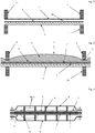
- Figure 1 there is shown the assembly of a section of the cell comprised between two cathodic supports according to a mechanical design in accordance with the technology known as "finite-gap".
- Figure 2 there is shown an assembly of a section of the cell comprised between two cathodic supports after a retrofitting according to the method of the invention.
- An electrolytic cell was assembled according to the method of the invention with a result according to the scheme of Figure 3 .
- the rigid cathode in form of 1 mm-thick sheet was bent in the regions between the contact surfaces with the cathodic supports in an area of about 2.5 mm.
- a conductive elastic element formed of interpenetrated coils of double nickel wires having a diameter of about 0.2 mm was also shaped by rolling so as to obtain compressed areas in correspondence of the areas of the rigid cathode in contact with the cathodic supports.
- a 0.3 mm-thick flexible cathodic mesh provided with a catalytic layer was then overlaid in intimate contact with the conductive elastic element.
- a0.5 mm-thick planar titanium mesh coated with a catalytic layer of mixed oxides of platinum group metals was welded onto the pre-existing louver anode. The above elements were then assembled, obtaining a cell structure according to Figure 3 .
- the cells were characterised by an average voltage of 2.90 V, which remained essentially unchanged after 6 months of operation, when the electrolysis was discontinued and two single cells were extracted from the supports, opened and subjected to visual inspection of the components.
- the inspection did not emphasise any alteration worthy of note, and in particular the two membranes presented a surface essentially free of notches or other types of traces generated by abnormal compression of the cathode.
- the above described electrolyser showed energy savings of about 150 kWh per tonne of product caustic soda with respect to to an electrolyser equipped with the original cells prior to retrofitting, characterised by a membrane-cathode gap of 1.5 mm.
Landscapes
- Chemical & Material Sciences (AREA)
- Engineering & Computer Science (AREA)
- Chemical Kinetics & Catalysis (AREA)
- Electrochemistry (AREA)
- Materials Engineering (AREA)
- Metallurgy (AREA)
- Organic Chemistry (AREA)
- Electrolytic Production Of Non-Metals, Compounds, Apparatuses Therefor (AREA)
- Electrodes For Compound Or Non-Metal Manufacture (AREA)
Description
- The invention relates to a method of retrofitting of membrane electrolysis cells assembled with finite interelectrode gap.
- Industrial electrolytic processes, for example the electrolysis of alkali brines, in particular of sodium chloride brine aimed at the production of chlorine, caustic soda and hydrogen, are commonly carried out in electrolysers consisting of a multiplicity of electrolytic cells divided by a separator, for example an ion-exchange membrane, into two compartments, anodic and cathodic, each containing an electrode.
- The basic design commonly utilised provides that the anode compartment contains a rigid anode generally consisting of a punched plate or expanded sheet or metal mesh coated with a superficial electrocatalytic film comprising noble metal oxides. The structure of the cathode compartment may provide different types of mechanical arrangement. More precisely, the installation of the cathodes in the cathode compartment can be made according to two basic mechanical designs. A first design provides the cathode in direct contact with the membrane (design known among those skilled in the art as "zero-gap"), a second design provides the cathode to be spaced away from the membrane with gaps of 1 - 3 mm (design known among those skilled in the art as "finite gap"). In this second type of technology, the need to maintain a certain distance between the anodic and cathodic surfaces, approximately 2 - 3 mm, entails the cell voltage to be penalised by a component associated with the ohmic drop generated by the current transport in the liquid phase between the cathode and the membrane: since the cell voltage is directly proportional to the energy consumption, normally expressed in kWh per tonne of chlorine or caustic soda, it follows that the overall economy of the process is disadvantaged. To overcome this problem, the design of membrane electrolytic cells, especially for chlor-alkali electrolysis, has undergone major changes in time that gave rise to cathodic structures capable of bringing the surface of the cathode in contact with the membrane, a result designated by the aforementioned definition of "zero-gap". In view of the increasingly high cost of energy and the unfavourable economy and feasibility entailed by a complete removal and replacement of "finite-gap" cells, it has been evidenced the need for a technology allowing to convert such cells present in electrolytic plants to the more efficient "zero-gap" technology taking advantage of the existing cell design and materials.
-
WO 03/102271 -
US 2005/173257 describes various methods to fix a gas diffusion electrode on the current collector by bending said gas diffusion electrode over its edges and fixing it to a corresponding bent current collector. -
WO 2010/055152 describes a cell that eliminates the cathode to anode gap by lowering cathodic strips, which require cell redesign and un-welding/welding operations. - Various aspects of the invention are set out in the accompanying claims.
- Under one aspect, the invention relates to a method of retrofitting of an electrolysis cell comprising a cathodic compartment delimited by a back-wall and an anodic compartment separated by an ion-exchange membrane, the cathode compartment containing a rigid cathode of planar geometry fixed to cathodic supports, the planar rigid cathode being maintained at a gap of 1 to 3 mm from the ion-exchange membrane, the anode compartment contains an anode in contact with the ion-exchange membrane, the method comprising the simultaneous or sequential steps of:
- shaping of said rigid cathode by plastic deformation of the regions comprised between the contact surfaces with said cathodic supports;
- overlaying onto said rigid cathode of a pre-shaped conductive elastic element having compressed regions in correspondence with the contact surfaces of said cathodic supports with said cathode;
- overlaying of a flexible planar cathode provided with a catalytic coating onto said conductive elastic element.
- By the above method, it is possible advantageously to convert an electrolytic cell of "finite-gap" technology design into an electrolytic cell of "zero-gap" technology design with no waste of material. Such a conversion, in fact, besides offering the advantage of a more even current distribution during operation, consequently minimising the voltages of the individual cells, on which the energy consumption depends, also allows reusing the cathode as current collector. Unwelding of the cathode with the consequent need of providing each cell with a new cathodic current collector is thereby avoided.
- The term "shaping by plastic deformation" is used herein to mean a deformation such that the rigid cathode is permanently curved in order to create a volume capable of receiving the suitably pre-shaped conductive elastic element.
- The method of the invention can be applied to electrolytic cells containing rigid planar cathodes for example in form of nickel punched metal sheet or mesh of thickness between 0.4 and 4 mm.
- The flexible planar cathode may be in form of a thin, nickel punched sheet or flexible planar mesh of thickness between 0.2 and 0.5 mm provided with an electrocatalytic film.
- In one embodiment, when an anode of so-called louver geometry is present in the cells to be retrofitted, the method according to the invention comprises the additional step of overlaying and fixing a planar anodic mesh provided with a catalytic coating onto the louver-shaped anode.
- The term "louver geometry" is used herein to mean geometry obtained by making cuts of suitable length in horizontal parallel and staggered rows on a metal sheet and subsequently deforming the sheet in correspondence of the cuts so as to form a plurality of tiles, for instance as described in
EP1641962 . - The overlaying and fixing, for example by welding, of an anodic mesh of planar geometry to the louvered anode allows the membrane, compressed on the cathode side according to the "zero-gap" design, to establish an adequate contact with the anode without being damaged.
- In one embodiment, the method according to the invention provides that the rigid planar cathode is shaped by plastic deformation of the regions comprised between the contact surfaces with the cathodic supports in the range of 1 to 5 mm.
- In one embodiment the pre-shaped conductive elastic element has compressed regions in correspondence with the contact surfaces of the rigid cathode with the cathodic supports of thickness below 1 mm.
- The cathodic supports may be in form of parallel ribs fixing the distance between the rigid cathode and the cathodic back-wall.
- The cathodic supports and the anodic supports may be made respectively of nickel and titanium.
- The conductive elastic element can be obtained for example by superposition of two or more conductive corrugated metal webs or from a mattress formed by interpenetrated coils obtained starting from one or more metal wires made of nickel typically having a total thickness of 2.5 to 5 mm.
- The catalytic film applied on the cathodes and anodes are catalytic films of compositions known in the art for evolution of hydrogen at the cathode side and of chlorine at the anode side, when the retrofitted cell is a cell for chlor-alkali electrolysis.
- Under a further aspect, the invention is related to an electrolysis cell comprising a cathodic compartment delimited by a cathodic back-wall and an anodic compartment separated by an ion-exchange membrane, the cathode compartment containing a rigid planar cathode fixed to cathodic supports, the anodic compartment containing an anode in uniform contact with the ion-exchange membrane, wherein the electrolysis cell is retrofitted with the rigid planar cathode being curved into a rigid current distributor having regions comprised between the contact surfaces with said cathodic supports plastically deformed along the vertical axis by 1 to 5 mm, with a conductive elastic element having regions of thickness in the range of 0.1 to 1 mm in correspondence with the contact surfaces of the rigid current distributor with the cathodic supports and with a flexible cathode consisting of a punched sheet or mesh of thickness ranging from 0.2 to 0.5 mm in uniform contact with the conductive elastic element on one side and with the ion-exchange membrane on the other side.
- In one embodiment of the electrolysis cell, the anode is made of a louver-shaped base with a planar punched sheet or mesh of thickness ranging from 0.3 to 1 mm and provided with an electrocatalytic film fixed thereon.
- Under a further aspect, the invention relates to an electrolyser consists of a modular arrangement of a multiplicity of elementary cells obtained by the above described method according to the invention.
- Some implementations exemplifying the method of retrofitting according to the invention will now be described with reference to the attached drawings, which have the sole purpose of illustrating the reciprocal arrangement of the different elements relatively to said particular implementations of the invention; in particular, drawings are not necessarily drawn to scale.
- In
Figure 1 there is shown the assembly of a section of the cell comprised between two cathodic supports according to a mechanical design in accordance with the technology known as "finite-gap". - In
Figure 2 there is shown an assembly of a section of the cell comprised between two cathodic supports after a retrofitting according to the method of the invention. - In
Figure 3 there is shown the assembly of a whole cell after a retrofitting according to the invention. -
-
Figure 1 shows a front view of a section of the cell comprised between twocathodic supports 4 and twoanodic supports 11 according to a mechanical design in accordance with the technology known as "finite-gap", a rigid current distributor of planar geometry acting ascathode 1 facing an ion-exchange membrane 2 at afinite gap 10.Membrane 2 is in its turn overlaid and in contact with an anode having alouvered geometry 3. -
Figure 2 shows a view of a detail offigure 3 . More precisely, there is shown a front view of a section of the cell comprised between twocathodic supports 4 and twoanodic supports 11 according to the invention. Acurrent distributor 1 is obtained by curving of thecathode 1 ofFigure 1 in theregions 12 in correspondence of saidcathodic supports 4. A pre-shaped conductiveelastic element 5 is in contact withcurrent distributor 1 on one side andflexible cathode 6 on the other, the latter being in intimate contact with ion-exchange membrane 2. Below ion-exchange membrane 2 there is depicted the anode comprised of a catalytically-coatedplanar mesh 7 welded on a portion of metal sheet oflouvered geometry 3. -
Figure 3 shows a front view of an electrolytic cell according to the invention wherein the two cathodic and anodic shells, respectively indicated with 8 and 9, cathodiccurrent distributor 1, cathodic and anodic supports, respectively indicated with 4 and 11, the anode comprised oflouver sheet 3 welded to planar catalysedanode mesh 7 andflexible cathode 6 are shown. - An electrolytic cell was assembled according to the method of the invention with a result according to the scheme of
Figure 3 . Starting from the components of a cell assembled in accordance to a "finite-gap" design, the following operations were carried out. The rigid cathode in form of 1 mm-thick sheet was bent in the regions between the contact surfaces with the cathodic supports in an area of about 2.5 mm. A conductive elastic element formed of interpenetrated coils of double nickel wires having a diameter of about 0.2 mm was also shaped by rolling so as to obtain compressed areas in correspondence of the areas of the rigid cathode in contact with the cathodic supports. A 0.3 mm-thick flexible cathodic mesh provided with a catalytic layer was then overlaid in intimate contact with the conductive elastic element. In the anodic compartment of the cell a0.5 mm-thick planar titanium mesh coated with a catalytic layer of mixed oxides of platinum group metals was welded onto the pre-existing louver anode. The above elements were then assembled, obtaining a cell structure according toFigure 3 . - The efficacy of cancelling the cathode-membrane gap by the retrofitting of a cathode of a cell originally having an internal geometry of "finite-gap" type and the installation of a new cathode coupled to a compressing elastic element as described in Example 1 was tested on a pilot electrolyser used for chlor-alkali membrane electrolysis. The electrolyser was equipped with eight single cells. The electrolyser was operated with 32% by weight caustic soda, sodium chloride brine at an outlet concentration of 210 g/l, at 90°C and at a current density of 5 kA/m2. After a stabilisation period of about 1 week, the cells were characterised by an average voltage of 2.90 V, which remained essentially unchanged after 6 months of operation, when the electrolysis was discontinued and two single cells were extracted from the supports, opened and subjected to visual inspection of the components. The inspection did not emphasise any alteration worthy of note, and in particular the two membranes presented a surface essentially free of notches or other types of traces generated by abnormal compression of the cathode. As a term of comparison, the above described electrolyser showed energy savings of about 150 kWh per tonne of product caustic soda with respect to to an electrolyser equipped with the original cells prior to retrofitting, characterised by a membrane-cathode gap of 1.5 mm.
- The previous description shall not be intended as limiting the invention, which may be used according to different embodiments without departing from the scopes thereof, and whose extent is solely defined by the appended claims.
- Throughout the description and claims of the present application, the term "comprise" and variations thereof such as "comprising" and "comprises" are not intended to exclude the presence of other elements, components or additional process steps.
- The discussion of documents, acts, materials, devices, articles and the like is included in this specification solely for the purpose of providing a context for the present invention. It is not suggested or represented that any or all of these matters formed part of the prior art base or were common general knowledge in the field relevant to the present invention before the priority date of each claim of this application.
Claims (10)
- Method of retrofitting of an electrolysis cell comprising a cathodic compartment delimited by a cathodic back-wall and anodic compartment, separated by an ion-exchange membrane, said cathodic compartment containing a rigid planar cathode fixed to cathodic supports, said rigid planar cathode being spaced apart by 0.4 to 4 mm from said ion-exchange membrane, said anodic compartment containing an anode in contact with said ion-exchange membrane, the method comprising the simultaneous or sequential steps of:- shaping of said rigid cathode by plastic deformation of the regions in correspondence of said cathodic supports;- overlaying onto said rigid cathode of a pre-shaped conductive elastic element having compressed regions in correspondence of said cathodic supports;- overlaying of a flexible planar cathode provided with a catalytic coating onto said conductive elastic element.
- Method according to claim 1, wherein said anode in contact with said ion-exchange membrane is a louver-shaped anode, the method comprising the additional step of overlaying and fixing a planar anodic mesh provided with a catalytic coating onto said louver-shaped anode.
- Method according to any one of claims 1 or 2 wherein said planar rigid cathode is shaped by plastic deformation of the regions in correspondence of said cathodic supports in the range of 1 to 5 mm.
- Method according to any one of claims 1, 2 or 3 wherein said pre-shaped conductive elastic element has compressed regions in correspondence of said cathodic supports having a thickness below 1 mm.
- Method according to any one of claims 1, 2, 3, or 4 wherein said planar rigid cathode consists of a punched sheet or expanded sheet or mesh made of nickel, provided with an electrocatalytic film for hydrogen evolution.
- Method according to claim 2, wherein said planar anodic mesh is made of titanium and provided with an electrocatalytic film for chlorine evolution.
- Method according to any one of claims 1 to 6 wherein said cathodic supports consist of parallel ribs setting the distance between the rigid cathode and the cathodic back-wall.
- Electrolysis cell comprising a cathodic compartment delimited by a cathodic back-wall and an anodic compartment separated by an ion-exchange membrane, said cathodic compartment containing a rigid planar cathode fixed to cathodic supports, said anodic compartment containing an anode in uniform contact with said ion-exchange membrane, wherein said electrolysis cell is retrofitted with said rigid planar cathode being curved into a rigid current distributor having regions comprised between said cathodic supports plastically deformed along the vertical axis by 1 to 5 mm, with a conductive elastic element having regions of thickness in the range of 0.1 to 1 mm in correspondence of said cathodic supports and with a flexible cathode consisting of a punched sheet or mesh of thickness ranging from 0.2 to 0.5 mm in uniform contact with said conductive elastic element on one side and with said ion-exchange membrane on the other side.
- Electrolysis cell according to claim 8, wherein said anode is made of a louver-shaped base with a planar punched sheet or mesh of thickness ranging from 0.3 to 1 mm and provided with an electrocatalytic film fixed thereon.
- Electrolyser consisting of a modular arrangement of a multiplicity of elementary cells according to any one of claims 8 or 9.
Priority Applications (1)
| Application Number | Priority Date | Filing Date | Title |
|---|---|---|---|
| PL14720060T PL2984208T3 (en) | 2013-04-10 | 2014-04-10 | Method of retrofitting of finite-gap electrolytic cells |
Applications Claiming Priority (2)
| Application Number | Priority Date | Filing Date | Title |
|---|---|---|---|
| IT000563A ITMI20130563A1 (en) | 2013-04-10 | 2013-04-10 | METHOD OF ADAPTATION OF ELECTROLYTIC CELLS HAVING FINISHED INTERELECTRODUCTS DISTANCES |
| PCT/EP2014/057250 WO2014167048A1 (en) | 2013-04-10 | 2014-04-10 | Method of retrofitting of finite-gap electrolytic cells |
Publications (2)
| Publication Number | Publication Date |
|---|---|
| EP2984208A1 EP2984208A1 (en) | 2016-02-17 |
| EP2984208B1 true EP2984208B1 (en) | 2017-02-01 |
Family
ID=48446459
Family Applications (1)
| Application Number | Title | Priority Date | Filing Date |
|---|---|---|---|
| EP14720060.4A Active EP2984208B1 (en) | 2013-04-10 | 2014-04-10 | Method of retrofitting of finite-gap electrolytic cells |
Country Status (11)
| Country | Link |
|---|---|
| US (1) | US9797051B2 (en) |
| EP (1) | EP2984208B1 (en) |
| JP (1) | JP6423856B2 (en) |
| KR (1) | KR102274662B1 (en) |
| CN (2) | CN105209665B (en) |
| BR (1) | BR112015025751B1 (en) |
| CA (1) | CA2900436C (en) |
| EA (1) | EA028920B1 (en) |
| IT (1) | ITMI20130563A1 (en) |
| PL (1) | PL2984208T3 (en) |
| WO (1) | WO2014167048A1 (en) |
Families Citing this family (8)
| Publication number | Priority date | Publication date | Assignee | Title |
|---|---|---|---|---|
| DE102018209520A1 (en) * | 2018-06-14 | 2019-12-19 | Thyssenkrupp Uhde Chlorine Engineers Gmbh | electrolysis cell |
| KR102475637B1 (en) * | 2018-07-06 | 2022-12-07 | 아사히 가세이 가부시키가이샤 | Electrode structure, method for producing electrode structure, electrolysis cell, and electrolysis tank |
| WO2021172508A1 (en) * | 2020-02-26 | 2021-09-02 | 旭化成株式会社 | Electrolytic tank and method for manufacturing electrolytic tank |
| US20230183876A1 (en) * | 2020-04-10 | 2023-06-15 | Idemitsu Kosan Co.,Ltd. | Li ION RECOVERY MEMBER AND Li RECOVERY DEVICE USING SAME |
| JP2024545332A (en) | 2021-12-22 | 2024-12-05 | ザ・リサーチ・ファウンデーション・フォー・ザ・ステイト・ユニヴァーシティ・オブ・ニューヨーク | Systems and methods for electrochemical marine alkalinity enhancement |
| EP4339335A1 (en) * | 2022-09-15 | 2024-03-20 | thyssenkrupp nucera AG & Co. KGaA | Electrolysis cell |
| CN116833283B (en) * | 2023-08-31 | 2023-10-31 | 江苏金松新材料有限公司 | Elastic structure flow field net and processing stamping equipment and processing technology thereof |
| EP4707428A1 (en) * | 2024-09-04 | 2026-03-11 | thyssenkrupp nucera AG & Co. KGaA | Method for refurbishing an electrolysis cell and electrolysis cell |
Family Cites Families (23)
| Publication number | Priority date | Publication date | Assignee | Title |
|---|---|---|---|---|
| US4923583A (en) * | 1985-11-04 | 1990-05-08 | Olin Corporation | Electrode elements for filter press membrane electrolytic cells |
| US5454925A (en) * | 1994-05-03 | 1995-10-03 | Eltech Systems Corporation | Repair of mesh electrode spaced from electrode pan |
| JP3122734B2 (en) * | 1995-03-23 | 2001-01-09 | 工業技術院長 | Water electrolysis tank using solid polymer electrolyte membrane |
| CA2157827C (en) * | 1995-09-08 | 2000-04-25 | Charles P. Tomba | Combination inner plate and outer envelope electrodes |
| IT1282367B1 (en) * | 1996-01-19 | 1998-03-20 | De Nora Spa | IMPROVED METHOD FOR THE ELECTROLYSIS OF WATER SOLUTIONS OF HYDROCHLORIC ACID |
| JP3553775B2 (en) * | 1997-10-16 | 2004-08-11 | ペルメレック電極株式会社 | Electrolyzer using gas diffusion electrode |
| JP3686270B2 (en) * | 1998-12-10 | 2005-08-24 | 株式会社トクヤマ | Electrolytic cell |
| US6423194B1 (en) * | 1999-02-25 | 2002-07-23 | Nagakazu Furuya | Gas diffusion electrode and brine electrolytic bath |
| ITMI20010401A1 (en) * | 2001-02-28 | 2002-08-28 | Nora Tecnologie Elettrochimich | NEW BIPOLAR ASSEMBLY FOR FILTER-PRESS ELECTROLIZER |
| DE10138214A1 (en) * | 2001-08-03 | 2003-02-20 | Bayer Ag | Chlorine generation electrolysis cell, having low operating voltage, has anode frame retained in a flexible array on cathode frame, cation exchange membrane, anode, gas diffusion electrode and current collector |
| US6797136B2 (en) * | 2001-09-07 | 2004-09-28 | Akzo Nobel N.V. | Electrolytic cell |
| DE10148600A1 (en) * | 2001-10-02 | 2003-04-10 | Bayer Ag | Electrolyzer used for electrolyzing hydrochloric acid has gas diffusion electrodes fixed to current collector |
| ITMI20012379A1 (en) * | 2001-11-12 | 2003-05-12 | Uhdenora Technologies Srl | ELECTROLYSIS CELL WITH GAS DIFFUSION ELECTRODES |
| ITMI20021203A1 (en) * | 2002-06-04 | 2003-12-04 | Uhdenora Technologies Srl | DISTRIBUTION ELEMENT FOR ELECTROCHEMISTRY WITH ELECTROLYTE PERCOLATION |
| DE10249508A1 (en) * | 2002-10-23 | 2004-05-06 | Uhde Gmbh | Electrolysis cell with an inner channel |
| US7303661B2 (en) * | 2003-03-31 | 2007-12-04 | Chlorine Engineers Corp., Ltd. | Electrode for electrolysis and ion exchange membrane electrolytic cell |
| JP2007084907A (en) * | 2005-09-26 | 2007-04-05 | Chlorine Eng Corp Ltd | Cubic electrode for electrolysis, and ion exchange membrane electrolytic cell |
| ITMI20060054A1 (en) * | 2006-01-16 | 2007-07-17 | Uhdenora Spa | ELASTIC CURRENT DISTRIBUTOR FOR PERCOLATOR CELLS |
| DE102006046808A1 (en) * | 2006-09-29 | 2008-04-03 | Uhdenora S.P.A. | Electrolysis cell used for chlor-alkali electrolysis comprises one electrode curved between two bars in the direction of the opposite-lying electrode |
| RU2427669C2 (en) * | 2006-09-29 | 2011-08-27 | Уденора С.П.А. | Electrolytic cell |
| ITMI20071375A1 (en) * | 2007-07-10 | 2009-01-11 | Uhdenora Spa | ELASTIC CURRENT MANIFOLD FOR ELECTROCHEMICAL CELLS |
| IT1391774B1 (en) * | 2008-11-17 | 2012-01-27 | Uhdenora Spa | ELEMENTARY CELL AND RELATIVE MODULAR ELECTROLISER FOR ELECTROLYTIC PROCESSES |
| JP5583002B2 (en) * | 2010-12-28 | 2014-09-03 | 東ソー株式会社 | Ion exchange membrane electrolytic cell |
-
2013
- 2013-04-10 IT IT000563A patent/ITMI20130563A1/en unknown
-
2014
- 2014-04-10 KR KR1020157031828A patent/KR102274662B1/en not_active Expired - Fee Related
- 2014-04-10 CA CA2900436A patent/CA2900436C/en active Active
- 2014-04-10 BR BR112015025751-8A patent/BR112015025751B1/en not_active IP Right Cessation
- 2014-04-10 JP JP2016506972A patent/JP6423856B2/en active Active
- 2014-04-10 US US14/783,324 patent/US9797051B2/en not_active Expired - Fee Related
- 2014-04-10 WO PCT/EP2014/057250 patent/WO2014167048A1/en not_active Ceased
- 2014-04-10 PL PL14720060T patent/PL2984208T3/en unknown
- 2014-04-10 CN CN201480019509.9A patent/CN105209665B/en active Active
- 2014-04-10 CN CN201420175516.5U patent/CN203904468U/en not_active Expired - Lifetime
- 2014-04-10 EP EP14720060.4A patent/EP2984208B1/en active Active
- 2014-04-10 EA EA201591914A patent/EA028920B1/en not_active IP Right Cessation
Non-Patent Citations (1)
| Title |
|---|
| None * |
Also Published As
| Publication number | Publication date |
|---|---|
| KR20150140347A (en) | 2015-12-15 |
| EA201591914A1 (en) | 2016-02-29 |
| KR102274662B1 (en) | 2021-07-12 |
| PL2984208T3 (en) | 2017-07-31 |
| EA028920B1 (en) | 2018-01-31 |
| JP6423856B2 (en) | 2018-11-14 |
| CN105209665A (en) | 2015-12-30 |
| CA2900436A1 (en) | 2014-10-16 |
| WO2014167048A1 (en) | 2014-10-16 |
| JP2016518522A (en) | 2016-06-23 |
| US9797051B2 (en) | 2017-10-24 |
| BR112015025751A2 (en) | 2017-07-18 |
| CN105209665B (en) | 2017-11-21 |
| CN203904468U (en) | 2014-10-29 |
| BR112015025751B1 (en) | 2021-09-08 |
| CA2900436C (en) | 2021-02-16 |
| EP2984208A1 (en) | 2016-02-17 |
| ITMI20130563A1 (en) | 2014-10-11 |
| US20160032468A1 (en) | 2016-02-04 |
Similar Documents
| Publication | Publication Date | Title |
|---|---|---|
| US9797051B2 (en) | Method of retrofitting of finite-gap electrolytic cells | |
| US11643739B2 (en) | Anode for ion exchange membrane electrolysis vessel, and ion exchange membrane electrolysis vessel using same | |
| KR20220118556A (en) | Electrode structure, method for producing electrode structure, electrolysis cell, and electrolysis tank | |
| RU2009146284A (en) | ELECTRODE FOR MEMBRANE ELECTROLYZES CELLS | |
| US3948750A (en) | Hollow bipolar electrode | |
| JP6543277B2 (en) | Narrow gap non-split electrolytic cell | |
| US4132622A (en) | Bipolar electrode | |
| CN1723300A (en) | Distributing element for electrolyte percolation electrochemical cell | |
| US4236989A (en) | Electrolytic cell | |
| Lima et al. | Energy loss in electrochemical diaphragm process of chlorine and alkali industry–A collateral effect of the undesirable generation of chlorate | |
| CN100378249C (en) | Thin film electrolytic tank | |
| JP4088527B2 (en) | New bipolar assembly for press filtration electrolytic cell | |
| CA1134779A (en) | Electrolysis cell | |
| RU2293141C2 (en) | Diaphragm type electrolyzer with increased electrode surface for producing chlorine and caustic soda, method for making such electrolyzer | |
| US20060163081A1 (en) | Expandable anode for diaphragm cells | |
| US7704355B2 (en) | Anode for gas evolution reactions |
Legal Events
| Date | Code | Title | Description |
|---|---|---|---|
| PUAI | Public reference made under article 153(3) epc to a published international application that has entered the european phase |
Free format text: ORIGINAL CODE: 0009012 |
|
| 17P | Request for examination filed |
Effective date: 20151012 |
|
| AK | Designated contracting states |
Kind code of ref document: A1 Designated state(s): AL AT BE BG CH CY CZ DE DK EE ES FI FR GB GR HR HU IE IS IT LI LT LU LV MC MK MT NL NO PL PT RO RS SE SI SK SM TR |
|
| AX | Request for extension of the european patent |
Extension state: BA ME |
|
| DAX | Request for extension of the european patent (deleted) | ||
| RIN1 | Information on inventor provided before grant (corrected) |
Inventor name: DONST, DMITRI Inventor name: PEREGO, MICHELE Inventor name: HOORMANN, DIRK Inventor name: HOHENBERGER, CHRISTOPH Inventor name: HOFFMANN, PHILIPP Inventor name: WOLTERING, PETER Inventor name: FULVIO, FEDERICO Inventor name: FIORUCCI, ALESSANDRO |
|
| GRAP | Despatch of communication of intention to grant a patent |
Free format text: ORIGINAL CODE: EPIDOSNIGR1 |
|
| INTG | Intention to grant announced |
Effective date: 20160810 |
|
| STAA | Information on the status of an ep patent application or granted ep patent |
Free format text: STATUS: GRANT OF PATENT IS INTENDED |
|
| GRAS | Grant fee paid |
Free format text: ORIGINAL CODE: EPIDOSNIGR3 |
|
| GRAA | (expected) grant |
Free format text: ORIGINAL CODE: 0009210 |
|
| STAA | Information on the status of an ep patent application or granted ep patent |
Free format text: STATUS: THE PATENT HAS BEEN GRANTED |
|
| AK | Designated contracting states |
Kind code of ref document: B1 Designated state(s): AL AT BE BG CH CY CZ DE DK EE ES FI FR GB GR HR HU IE IS IT LI LT LU LV MC MK MT NL NO PL PT RO RS SE SI SK SM TR |
|
| REG | Reference to a national code |
Ref country code: GB Ref legal event code: FG4D |
|
| REG | Reference to a national code |
Ref country code: CH Ref legal event code: EP Ref country code: AT Ref legal event code: REF Ref document number: 865683 Country of ref document: AT Kind code of ref document: T Effective date: 20170215 |
|
| REG | Reference to a national code |
Ref country code: IE Ref legal event code: FG4D |
|
| REG | Reference to a national code |
Ref country code: DE Ref legal event code: R096 Ref document number: 602014006608 Country of ref document: DE |
|
| REG | Reference to a national code |
Ref country code: NL Ref legal event code: FP |
|
| REG | Reference to a national code |
Ref country code: SE Ref legal event code: TRGR |
|
| REG | Reference to a national code |
Ref country code: LT Ref legal event code: MG4D |
|
| PG25 | Lapsed in a contracting state [announced via postgrant information from national office to epo] |
Ref country code: IS Free format text: LAPSE BECAUSE OF FAILURE TO SUBMIT A TRANSLATION OF THE DESCRIPTION OR TO PAY THE FEE WITHIN THE PRESCRIBED TIME-LIMIT Effective date: 20170601 Ref country code: HR Free format text: LAPSE BECAUSE OF FAILURE TO SUBMIT A TRANSLATION OF THE DESCRIPTION OR TO PAY THE FEE WITHIN THE PRESCRIBED TIME-LIMIT Effective date: 20170201 Ref country code: GR Free format text: LAPSE BECAUSE OF FAILURE TO SUBMIT A TRANSLATION OF THE DESCRIPTION OR TO PAY THE FEE WITHIN THE PRESCRIBED TIME-LIMIT Effective date: 20170502 Ref country code: FI Free format text: LAPSE BECAUSE OF FAILURE TO SUBMIT A TRANSLATION OF THE DESCRIPTION OR TO PAY THE FEE WITHIN THE PRESCRIBED TIME-LIMIT Effective date: 20170201 Ref country code: NO Free format text: LAPSE BECAUSE OF FAILURE TO SUBMIT A TRANSLATION OF THE DESCRIPTION OR TO PAY THE FEE WITHIN THE PRESCRIBED TIME-LIMIT Effective date: 20170501 Ref country code: LT Free format text: LAPSE BECAUSE OF FAILURE TO SUBMIT A TRANSLATION OF THE DESCRIPTION OR TO PAY THE FEE WITHIN THE PRESCRIBED TIME-LIMIT Effective date: 20170201 |
|
| PG25 | Lapsed in a contracting state [announced via postgrant information from national office to epo] |
Ref country code: PT Free format text: LAPSE BECAUSE OF FAILURE TO SUBMIT A TRANSLATION OF THE DESCRIPTION OR TO PAY THE FEE WITHIN THE PRESCRIBED TIME-LIMIT Effective date: 20170601 Ref country code: BG Free format text: LAPSE BECAUSE OF FAILURE TO SUBMIT A TRANSLATION OF THE DESCRIPTION OR TO PAY THE FEE WITHIN THE PRESCRIBED TIME-LIMIT Effective date: 20170501 Ref country code: LV Free format text: LAPSE BECAUSE OF FAILURE TO SUBMIT A TRANSLATION OF THE DESCRIPTION OR TO PAY THE FEE WITHIN THE PRESCRIBED TIME-LIMIT Effective date: 20170201 Ref country code: RS Free format text: LAPSE BECAUSE OF FAILURE TO SUBMIT A TRANSLATION OF THE DESCRIPTION OR TO PAY THE FEE WITHIN THE PRESCRIBED TIME-LIMIT Effective date: 20170201 Ref country code: ES Free format text: LAPSE BECAUSE OF FAILURE TO SUBMIT A TRANSLATION OF THE DESCRIPTION OR TO PAY THE FEE WITHIN THE PRESCRIBED TIME-LIMIT Effective date: 20170201 |
|
| PG25 | Lapsed in a contracting state [announced via postgrant information from national office to epo] |
Ref country code: CZ Free format text: LAPSE BECAUSE OF FAILURE TO SUBMIT A TRANSLATION OF THE DESCRIPTION OR TO PAY THE FEE WITHIN THE PRESCRIBED TIME-LIMIT Effective date: 20170201 Ref country code: RO Free format text: LAPSE BECAUSE OF FAILURE TO SUBMIT A TRANSLATION OF THE DESCRIPTION OR TO PAY THE FEE WITHIN THE PRESCRIBED TIME-LIMIT Effective date: 20170201 Ref country code: EE Free format text: LAPSE BECAUSE OF FAILURE TO SUBMIT A TRANSLATION OF THE DESCRIPTION OR TO PAY THE FEE WITHIN THE PRESCRIBED TIME-LIMIT Effective date: 20170201 Ref country code: SK Free format text: LAPSE BECAUSE OF FAILURE TO SUBMIT A TRANSLATION OF THE DESCRIPTION OR TO PAY THE FEE WITHIN THE PRESCRIBED TIME-LIMIT Effective date: 20170201 |
|
| REG | Reference to a national code |
Ref country code: DE Ref legal event code: R119 Ref document number: 602014006608 Country of ref document: DE |
|
| PG25 | Lapsed in a contracting state [announced via postgrant information from national office to epo] |
Ref country code: SM Free format text: LAPSE BECAUSE OF FAILURE TO SUBMIT A TRANSLATION OF THE DESCRIPTION OR TO PAY THE FEE WITHIN THE PRESCRIBED TIME-LIMIT Effective date: 20170201 Ref country code: DK Free format text: LAPSE BECAUSE OF FAILURE TO SUBMIT A TRANSLATION OF THE DESCRIPTION OR TO PAY THE FEE WITHIN THE PRESCRIBED TIME-LIMIT Effective date: 20170201 |
|
| REG | Reference to a national code |
Ref country code: CH Ref legal event code: PL |
|
| PLBE | No opposition filed within time limit |
Free format text: ORIGINAL CODE: 0009261 |
|
| STAA | Information on the status of an ep patent application or granted ep patent |
Free format text: STATUS: NO OPPOSITION FILED WITHIN TIME LIMIT |
|
| 26N | No opposition filed |
Effective date: 20171103 |
|
| REG | Reference to a national code |
Ref country code: IE Ref legal event code: MM4A |
|
| REG | Reference to a national code |
Ref country code: FR Ref legal event code: ST Effective date: 20171229 |
|
| PG25 | Lapsed in a contracting state [announced via postgrant information from national office to epo] |
Ref country code: MC Free format text: LAPSE BECAUSE OF FAILURE TO SUBMIT A TRANSLATION OF THE DESCRIPTION OR TO PAY THE FEE WITHIN THE PRESCRIBED TIME-LIMIT Effective date: 20170201 Ref country code: DE Free format text: LAPSE BECAUSE OF NON-PAYMENT OF DUE FEES Effective date: 20171103 Ref country code: FR Free format text: LAPSE BECAUSE OF NON-PAYMENT OF DUE FEES Effective date: 20170502 |
|
| PG25 | Lapsed in a contracting state [announced via postgrant information from national office to epo] |
Ref country code: SI Free format text: LAPSE BECAUSE OF FAILURE TO SUBMIT A TRANSLATION OF THE DESCRIPTION OR TO PAY THE FEE WITHIN THE PRESCRIBED TIME-LIMIT Effective date: 20170201 Ref country code: LI Free format text: LAPSE BECAUSE OF NON-PAYMENT OF DUE FEES Effective date: 20170430 Ref country code: LU Free format text: LAPSE BECAUSE OF NON-PAYMENT OF DUE FEES Effective date: 20170410 Ref country code: CH Free format text: LAPSE BECAUSE OF NON-PAYMENT OF DUE FEES Effective date: 20170430 |
|
| PG25 | Lapsed in a contracting state [announced via postgrant information from national office to epo] |
Ref country code: IE Free format text: LAPSE BECAUSE OF NON-PAYMENT OF DUE FEES Effective date: 20170410 |
|
| PG25 | Lapsed in a contracting state [announced via postgrant information from national office to epo] |
Ref country code: MT Free format text: LAPSE BECAUSE OF NON-PAYMENT OF DUE FEES Effective date: 20170410 |
|
| PG25 | Lapsed in a contracting state [announced via postgrant information from national office to epo] |
Ref country code: HU Free format text: LAPSE BECAUSE OF FAILURE TO SUBMIT A TRANSLATION OF THE DESCRIPTION OR TO PAY THE FEE WITHIN THE PRESCRIBED TIME-LIMIT; INVALID AB INITIO Effective date: 20140410 |
|
| PG25 | Lapsed in a contracting state [announced via postgrant information from national office to epo] |
Ref country code: CY Free format text: LAPSE BECAUSE OF FAILURE TO SUBMIT A TRANSLATION OF THE DESCRIPTION OR TO PAY THE FEE WITHIN THE PRESCRIBED TIME-LIMIT Effective date: 20170201 |
|
| REG | Reference to a national code |
Ref country code: AT Ref legal event code: UEP Ref document number: 865683 Country of ref document: AT Kind code of ref document: T Effective date: 20170201 |
|
| PG25 | Lapsed in a contracting state [announced via postgrant information from national office to epo] |
Ref country code: MK Free format text: LAPSE BECAUSE OF FAILURE TO SUBMIT A TRANSLATION OF THE DESCRIPTION OR TO PAY THE FEE WITHIN THE PRESCRIBED TIME-LIMIT Effective date: 20170201 |
|
| PG25 | Lapsed in a contracting state [announced via postgrant information from national office to epo] |
Ref country code: TR Free format text: LAPSE BECAUSE OF FAILURE TO SUBMIT A TRANSLATION OF THE DESCRIPTION OR TO PAY THE FEE WITHIN THE PRESCRIBED TIME-LIMIT Effective date: 20170201 |
|
| PG25 | Lapsed in a contracting state [announced via postgrant information from national office to epo] |
Ref country code: AL Free format text: LAPSE BECAUSE OF FAILURE TO SUBMIT A TRANSLATION OF THE DESCRIPTION OR TO PAY THE FEE WITHIN THE PRESCRIBED TIME-LIMIT Effective date: 20170201 |
|
| PGFP | Annual fee paid to national office [announced via postgrant information from national office to epo] |
Ref country code: PL Payment date: 20230330 Year of fee payment: 10 |
|
| PGFP | Annual fee paid to national office [announced via postgrant information from national office to epo] |
Ref country code: IT Payment date: 20230426 Year of fee payment: 10 |
|
| PGFP | Annual fee paid to national office [announced via postgrant information from national office to epo] |
Ref country code: SE Payment date: 20230420 Year of fee payment: 10 Ref country code: AT Payment date: 20230420 Year of fee payment: 10 |
|
| REG | Reference to a national code |
Ref country code: SE Ref legal event code: EUG |
|
| REG | Reference to a national code |
Ref country code: AT Ref legal event code: MM01 Ref document number: 865683 Country of ref document: AT Kind code of ref document: T Effective date: 20240410 |
|
| PG25 | Lapsed in a contracting state [announced via postgrant information from national office to epo] |
Ref country code: AT Free format text: LAPSE BECAUSE OF NON-PAYMENT OF DUE FEES Effective date: 20240410 |
|
| PG25 | Lapsed in a contracting state [announced via postgrant information from national office to epo] |
Ref country code: AT Free format text: LAPSE BECAUSE OF NON-PAYMENT OF DUE FEES Effective date: 20240410 |
|
| PG25 | Lapsed in a contracting state [announced via postgrant information from national office to epo] |
Ref country code: IT Free format text: LAPSE BECAUSE OF NON-PAYMENT OF DUE FEES Effective date: 20240410 |
|
| PGFP | Annual fee paid to national office [announced via postgrant information from national office to epo] |
Ref country code: NL Payment date: 20250418 Year of fee payment: 12 |
|
| PG25 | Lapsed in a contracting state [announced via postgrant information from national office to epo] |
Ref country code: PL Free format text: LAPSE BECAUSE OF NON-PAYMENT OF DUE FEES Effective date: 20240410 |
|
| PGFP | Annual fee paid to national office [announced via postgrant information from national office to epo] |
Ref country code: GB Payment date: 20250423 Year of fee payment: 12 |
|
| PGFP | Annual fee paid to national office [announced via postgrant information from national office to epo] |
Ref country code: BE Payment date: 20250418 Year of fee payment: 12 |
|
| PG25 | Lapsed in a contracting state [announced via postgrant information from national office to epo] |
Ref country code: SE Free format text: LAPSE BECAUSE OF NON-PAYMENT OF DUE FEES Effective date: 20240411 |