EP2984045B1 - A method afor electrostatic treatment of fluids comprising three phases: the treatment phase, the mixing phase, and the usage phase which are spatially and temporally decoupled - Google Patents
A method afor electrostatic treatment of fluids comprising three phases: the treatment phase, the mixing phase, and the usage phase which are spatially and temporally decoupled Download PDFInfo
- Publication number
- EP2984045B1 EP2984045B1 EP14723727.5A EP14723727A EP2984045B1 EP 2984045 B1 EP2984045 B1 EP 2984045B1 EP 14723727 A EP14723727 A EP 14723727A EP 2984045 B1 EP2984045 B1 EP 2984045B1
- Authority
- EP
- European Patent Office
- Prior art keywords
- fluid
- ionized
- treatment
- phase
- directly
- Prior art date
- Legal status (The legal status is an assumption and is not a legal conclusion. Google has not performed a legal analysis and makes no representation as to the accuracy of the status listed.)
- Active
Links
- 239000012530 fluid Substances 0.000 title claims description 531
- 238000002156 mixing Methods 0.000 title claims description 170
- 238000000034 method Methods 0.000 title claims description 146
- 230000008569 process Effects 0.000 claims description 88
- 230000005291 magnetic effect Effects 0.000 claims description 39
- 238000003860 storage Methods 0.000 claims description 28
- 230000005686 electrostatic field Effects 0.000 claims description 22
- 230000005672 electromagnetic field Effects 0.000 claims description 14
- 239000012071 phase Substances 0.000 description 111
- XLYOFNOQVPJJNP-UHFFFAOYSA-N water Substances O XLYOFNOQVPJJNP-UHFFFAOYSA-N 0.000 description 63
- 239000000446 fuel Substances 0.000 description 62
- 238000004519 manufacturing process Methods 0.000 description 49
- 239000003502 gasoline Substances 0.000 description 41
- 239000003795 chemical substances by application Substances 0.000 description 19
- 238000012360 testing method Methods 0.000 description 17
- 230000001419 dependent effect Effects 0.000 description 13
- 230000000694 effects Effects 0.000 description 12
- 239000000126 substance Substances 0.000 description 12
- 230000004907 flux Effects 0.000 description 10
- 238000000151 deposition Methods 0.000 description 8
- 239000000203 mixture Substances 0.000 description 7
- 230000006872 improvement Effects 0.000 description 6
- 238000005259 measurement Methods 0.000 description 6
- 230000009467 reduction Effects 0.000 description 6
- 239000008346 aqueous phase Substances 0.000 description 5
- 238000005266 casting Methods 0.000 description 5
- 239000000919 ceramic Substances 0.000 description 5
- 238000002203 pretreatment Methods 0.000 description 5
- 230000006835 compression Effects 0.000 description 4
- 238000007906 compression Methods 0.000 description 4
- 238000011160 research Methods 0.000 description 4
- 230000002123 temporal effect Effects 0.000 description 4
- 238000002604 ultrasonography Methods 0.000 description 4
- 238000002485 combustion reaction Methods 0.000 description 3
- 238000001816 cooling Methods 0.000 description 3
- 239000010779 crude oil Substances 0.000 description 3
- 238000011049 filling Methods 0.000 description 3
- 238000010438 heat treatment Methods 0.000 description 3
- 229930195733 hydrocarbon Natural products 0.000 description 3
- 150000002430 hydrocarbons Chemical class 0.000 description 3
- 238000011068 loading method Methods 0.000 description 3
- 229940074869 marquis Drugs 0.000 description 3
- 244000005700 microbiome Species 0.000 description 3
- 230000004048 modification Effects 0.000 description 3
- 238000012986 modification Methods 0.000 description 3
- VBUNOIXRZNJNAD-UHFFFAOYSA-N ponazuril Chemical compound CC1=CC(N2C(N(C)C(=O)NC2=O)=O)=CC=C1OC1=CC=C(S(=O)(=O)C(F)(F)F)C=C1 VBUNOIXRZNJNAD-UHFFFAOYSA-N 0.000 description 3
- 238000002360 preparation method Methods 0.000 description 3
- 239000004215 Carbon black (E152) Substances 0.000 description 2
- 230000009471 action Effects 0.000 description 2
- 238000007792 addition Methods 0.000 description 2
- 230000008901 benefit Effects 0.000 description 2
- 230000003750 conditioning effect Effects 0.000 description 2
- 238000001739 density measurement Methods 0.000 description 2
- 230000009977 dual effect Effects 0.000 description 2
- ZZUFCTLCJUWOSV-UHFFFAOYSA-N furosemide Chemical compound C1=C(Cl)C(S(=O)(=O)N)=CC(C(O)=O)=C1NCC1=CC=CO1 ZZUFCTLCJUWOSV-UHFFFAOYSA-N 0.000 description 2
- 238000002347 injection Methods 0.000 description 2
- 239000007924 injection Substances 0.000 description 2
- 238000009434 installation Methods 0.000 description 2
- 230000033001 locomotion Effects 0.000 description 2
- 239000003209 petroleum derivative Substances 0.000 description 2
- 230000002265 prevention Effects 0.000 description 2
- 230000001953 sensory effect Effects 0.000 description 2
- 239000004071 soot Substances 0.000 description 2
- 239000004334 sorbic acid Substances 0.000 description 2
- 238000009210 therapy by ultrasound Methods 0.000 description 2
- 235000008733 Citrus aurantifolia Nutrition 0.000 description 1
- 235000011941 Tilia x europaea Nutrition 0.000 description 1
- 230000004913 activation Effects 0.000 description 1
- 230000001580 bacterial effect Effects 0.000 description 1
- 230000008859 change Effects 0.000 description 1
- 238000010276 construction Methods 0.000 description 1
- 239000000356 contaminant Substances 0.000 description 1
- 230000007797 corrosion Effects 0.000 description 1
- 238000005260 corrosion Methods 0.000 description 1
- 230000008878 coupling Effects 0.000 description 1
- 238000010168 coupling process Methods 0.000 description 1
- 238000005859 coupling reaction Methods 0.000 description 1
- 238000005202 decontamination Methods 0.000 description 1
- 230000003588 decontaminative effect Effects 0.000 description 1
- 230000007812 deficiency Effects 0.000 description 1
- 239000002283 diesel fuel Substances 0.000 description 1
- 239000006185 dispersion Substances 0.000 description 1
- 239000003651 drinking water Substances 0.000 description 1
- 235000020188 drinking water Nutrition 0.000 description 1
- 230000008030 elimination Effects 0.000 description 1
- 238000003379 elimination reaction Methods 0.000 description 1
- 239000000295 fuel oil Substances 0.000 description 1
- 230000036541 health Effects 0.000 description 1
- 239000003350 kerosene Substances 0.000 description 1
- 239000004571 lime Substances 0.000 description 1
- 239000002184 metal Substances 0.000 description 1
- 230000008635 plant growth Effects 0.000 description 1
- 230000005855 radiation Effects 0.000 description 1
- 230000003134 recirculating effect Effects 0.000 description 1
- 239000013535 sea water Substances 0.000 description 1
- 239000000243 solution Substances 0.000 description 1
- 238000006467 substitution reaction Methods 0.000 description 1
- 239000000725 suspension Substances 0.000 description 1
- 230000001360 synchronised effect Effects 0.000 description 1
Images


Classifications
-
- C—CHEMISTRY; METALLURGY
- C02—TREATMENT OF WATER, WASTE WATER, SEWAGE, OR SLUDGE
- C02F—TREATMENT OF WATER, WASTE WATER, SEWAGE, OR SLUDGE
- C02F1/00—Treatment of water, waste water, or sewage
- C02F1/48—Treatment of water, waste water, or sewage with magnetic or electric fields
- C02F1/481—Treatment of water, waste water, or sewage with magnetic or electric fields using permanent magnets
-
- C—CHEMISTRY; METALLURGY
- C02—TREATMENT OF WATER, WASTE WATER, SEWAGE, OR SLUDGE
- C02F—TREATMENT OF WATER, WASTE WATER, SEWAGE, OR SLUDGE
- C02F1/00—Treatment of water, waste water, or sewage
- C02F1/48—Treatment of water, waste water, or sewage with magnetic or electric fields
- C02F1/484—Treatment of water, waste water, or sewage with magnetic or electric fields using electromagnets
-
- C—CHEMISTRY; METALLURGY
- C10—PETROLEUM, GAS OR COKE INDUSTRIES; TECHNICAL GASES CONTAINING CARBON MONOXIDE; FUELS; LUBRICANTS; PEAT
- C10G—CRACKING HYDROCARBON OILS; PRODUCTION OF LIQUID HYDROCARBON MIXTURES, e.g. BY DESTRUCTIVE HYDROGENATION, OLIGOMERISATION, POLYMERISATION; RECOVERY OF HYDROCARBON OILS FROM OIL-SHALE, OIL-SAND, OR GASES; REFINING MIXTURES MAINLY CONSISTING OF HYDROCARBONS; REFORMING OF NAPHTHA; MINERAL WAXES
- C10G32/00—Refining of hydrocarbon oils by electric or magnetic means, by irradiation, or by using microorganisms
- C10G32/02—Refining of hydrocarbon oils by electric or magnetic means, by irradiation, or by using microorganisms by electric or magnetic means
-
- C—CHEMISTRY; METALLURGY
- C10—PETROLEUM, GAS OR COKE INDUSTRIES; TECHNICAL GASES CONTAINING CARBON MONOXIDE; FUELS; LUBRICANTS; PEAT
- C10G—CRACKING HYDROCARBON OILS; PRODUCTION OF LIQUID HYDROCARBON MIXTURES, e.g. BY DESTRUCTIVE HYDROGENATION, OLIGOMERISATION, POLYMERISATION; RECOVERY OF HYDROCARBON OILS FROM OIL-SHALE, OIL-SAND, OR GASES; REFINING MIXTURES MAINLY CONSISTING OF HYDROCARBONS; REFORMING OF NAPHTHA; MINERAL WAXES
- C10G33/00—Dewatering or demulsification of hydrocarbon oils
- C10G33/02—Dewatering or demulsification of hydrocarbon oils with electrical or magnetic means
-
- C—CHEMISTRY; METALLURGY
- C10—PETROLEUM, GAS OR COKE INDUSTRIES; TECHNICAL GASES CONTAINING CARBON MONOXIDE; FUELS; LUBRICANTS; PEAT
- C10L—FUELS NOT OTHERWISE PROVIDED FOR; NATURAL GAS; SYNTHETIC NATURAL GAS OBTAINED BY PROCESSES NOT COVERED BY SUBCLASSES C10G, C10K; LIQUEFIED PETROLEUM GAS; ADDING MATERIALS TO FUELS OR FIRES TO REDUCE SMOKE OR UNDESIRABLE DEPOSITS OR TO FACILITATE SOOT REMOVAL; FIRELIGHTERS
- C10L1/00—Liquid carbonaceous fuels
- C10L1/04—Liquid carbonaceous fuels essentially based on blends of hydrocarbons
- C10L1/06—Liquid carbonaceous fuels essentially based on blends of hydrocarbons for spark ignition
-
- C—CHEMISTRY; METALLURGY
- C10—PETROLEUM, GAS OR COKE INDUSTRIES; TECHNICAL GASES CONTAINING CARBON MONOXIDE; FUELS; LUBRICANTS; PEAT
- C10L—FUELS NOT OTHERWISE PROVIDED FOR; NATURAL GAS; SYNTHETIC NATURAL GAS OBTAINED BY PROCESSES NOT COVERED BY SUBCLASSES C10G, C10K; LIQUEFIED PETROLEUM GAS; ADDING MATERIALS TO FUELS OR FIRES TO REDUCE SMOKE OR UNDESIRABLE DEPOSITS OR TO FACILITATE SOOT REMOVAL; FIRELIGHTERS
- C10L1/00—Liquid carbonaceous fuels
- C10L1/04—Liquid carbonaceous fuels essentially based on blends of hydrocarbons
- C10L1/08—Liquid carbonaceous fuels essentially based on blends of hydrocarbons for compression ignition
-
- C—CHEMISTRY; METALLURGY
- C10—PETROLEUM, GAS OR COKE INDUSTRIES; TECHNICAL GASES CONTAINING CARBON MONOXIDE; FUELS; LUBRICANTS; PEAT
- C10L—FUELS NOT OTHERWISE PROVIDED FOR; NATURAL GAS; SYNTHETIC NATURAL GAS OBTAINED BY PROCESSES NOT COVERED BY SUBCLASSES C10G, C10K; LIQUEFIED PETROLEUM GAS; ADDING MATERIALS TO FUELS OR FIRES TO REDUCE SMOKE OR UNDESIRABLE DEPOSITS OR TO FACILITATE SOOT REMOVAL; FIRELIGHTERS
- C10L10/00—Use of additives to fuels or fires for particular purposes
- C10L10/02—Use of additives to fuels or fires for particular purposes for reducing smoke development
-
- C—CHEMISTRY; METALLURGY
- C10—PETROLEUM, GAS OR COKE INDUSTRIES; TECHNICAL GASES CONTAINING CARBON MONOXIDE; FUELS; LUBRICANTS; PEAT
- C10L—FUELS NOT OTHERWISE PROVIDED FOR; NATURAL GAS; SYNTHETIC NATURAL GAS OBTAINED BY PROCESSES NOT COVERED BY SUBCLASSES C10G, C10K; LIQUEFIED PETROLEUM GAS; ADDING MATERIALS TO FUELS OR FIRES TO REDUCE SMOKE OR UNDESIRABLE DEPOSITS OR TO FACILITATE SOOT REMOVAL; FIRELIGHTERS
- C10L2200/00—Components of fuel compositions
- C10L2200/04—Organic compounds
- C10L2200/0407—Specifically defined hydrocarbon fractions as obtained from, e.g. a distillation column
- C10L2200/0415—Light distillates, e.g. LPG, naphtha
- C10L2200/0423—Gasoline
-
- C—CHEMISTRY; METALLURGY
- C10—PETROLEUM, GAS OR COKE INDUSTRIES; TECHNICAL GASES CONTAINING CARBON MONOXIDE; FUELS; LUBRICANTS; PEAT
- C10L—FUELS NOT OTHERWISE PROVIDED FOR; NATURAL GAS; SYNTHETIC NATURAL GAS OBTAINED BY PROCESSES NOT COVERED BY SUBCLASSES C10G, C10K; LIQUEFIED PETROLEUM GAS; ADDING MATERIALS TO FUELS OR FIRES TO REDUCE SMOKE OR UNDESIRABLE DEPOSITS OR TO FACILITATE SOOT REMOVAL; FIRELIGHTERS
- C10L2200/00—Components of fuel compositions
- C10L2200/04—Organic compounds
- C10L2200/0407—Specifically defined hydrocarbon fractions as obtained from, e.g. a distillation column
- C10L2200/0438—Middle or heavy distillates, heating oil, gasoil, marine fuels, residua
- C10L2200/0446—Diesel
-
- C—CHEMISTRY; METALLURGY
- C10—PETROLEUM, GAS OR COKE INDUSTRIES; TECHNICAL GASES CONTAINING CARBON MONOXIDE; FUELS; LUBRICANTS; PEAT
- C10L—FUELS NOT OTHERWISE PROVIDED FOR; NATURAL GAS; SYNTHETIC NATURAL GAS OBTAINED BY PROCESSES NOT COVERED BY SUBCLASSES C10G, C10K; LIQUEFIED PETROLEUM GAS; ADDING MATERIALS TO FUELS OR FIRES TO REDUCE SMOKE OR UNDESIRABLE DEPOSITS OR TO FACILITATE SOOT REMOVAL; FIRELIGHTERS
- C10L2230/00—Function and purpose of a components of a fuel or the composition as a whole
- C10L2230/22—Function and purpose of a components of a fuel or the composition as a whole for improving fuel economy or fuel efficiency
-
- C—CHEMISTRY; METALLURGY
- C10—PETROLEUM, GAS OR COKE INDUSTRIES; TECHNICAL GASES CONTAINING CARBON MONOXIDE; FUELS; LUBRICANTS; PEAT
- C10L—FUELS NOT OTHERWISE PROVIDED FOR; NATURAL GAS; SYNTHETIC NATURAL GAS OBTAINED BY PROCESSES NOT COVERED BY SUBCLASSES C10G, C10K; LIQUEFIED PETROLEUM GAS; ADDING MATERIALS TO FUELS OR FIRES TO REDUCE SMOKE OR UNDESIRABLE DEPOSITS OR TO FACILITATE SOOT REMOVAL; FIRELIGHTERS
- C10L2270/00—Specifically adapted fuels
- C10L2270/02—Specifically adapted fuels for internal combustion engines
- C10L2270/023—Specifically adapted fuels for internal combustion engines for gasoline engines
-
- C—CHEMISTRY; METALLURGY
- C10—PETROLEUM, GAS OR COKE INDUSTRIES; TECHNICAL GASES CONTAINING CARBON MONOXIDE; FUELS; LUBRICANTS; PEAT
- C10L—FUELS NOT OTHERWISE PROVIDED FOR; NATURAL GAS; SYNTHETIC NATURAL GAS OBTAINED BY PROCESSES NOT COVERED BY SUBCLASSES C10G, C10K; LIQUEFIED PETROLEUM GAS; ADDING MATERIALS TO FUELS OR FIRES TO REDUCE SMOKE OR UNDESIRABLE DEPOSITS OR TO FACILITATE SOOT REMOVAL; FIRELIGHTERS
- C10L2270/00—Specifically adapted fuels
- C10L2270/02—Specifically adapted fuels for internal combustion engines
- C10L2270/026—Specifically adapted fuels for internal combustion engines for diesel engines, e.g. automobiles, stationary, marine
-
- C—CHEMISTRY; METALLURGY
- C10—PETROLEUM, GAS OR COKE INDUSTRIES; TECHNICAL GASES CONTAINING CARBON MONOXIDE; FUELS; LUBRICANTS; PEAT
- C10L—FUELS NOT OTHERWISE PROVIDED FOR; NATURAL GAS; SYNTHETIC NATURAL GAS OBTAINED BY PROCESSES NOT COVERED BY SUBCLASSES C10G, C10K; LIQUEFIED PETROLEUM GAS; ADDING MATERIALS TO FUELS OR FIRES TO REDUCE SMOKE OR UNDESIRABLE DEPOSITS OR TO FACILITATE SOOT REMOVAL; FIRELIGHTERS
- C10L2290/00—Fuel preparation or upgrading, processes or apparatus therefore, comprising specific process steps or apparatus units
- C10L2290/24—Mixing, stirring of fuel components
-
- C—CHEMISTRY; METALLURGY
- C10—PETROLEUM, GAS OR COKE INDUSTRIES; TECHNICAL GASES CONTAINING CARBON MONOXIDE; FUELS; LUBRICANTS; PEAT
- C10L—FUELS NOT OTHERWISE PROVIDED FOR; NATURAL GAS; SYNTHETIC NATURAL GAS OBTAINED BY PROCESSES NOT COVERED BY SUBCLASSES C10G, C10K; LIQUEFIED PETROLEUM GAS; ADDING MATERIALS TO FUELS OR FIRES TO REDUCE SMOKE OR UNDESIRABLE DEPOSITS OR TO FACILITATE SOOT REMOVAL; FIRELIGHTERS
- C10L2290/00—Fuel preparation or upgrading, processes or apparatus therefore, comprising specific process steps or apparatus units
- C10L2290/38—Applying an electric field or inclusion of electrodes in the apparatus
-
- C—CHEMISTRY; METALLURGY
- C10—PETROLEUM, GAS OR COKE INDUSTRIES; TECHNICAL GASES CONTAINING CARBON MONOXIDE; FUELS; LUBRICANTS; PEAT
- C10L—FUELS NOT OTHERWISE PROVIDED FOR; NATURAL GAS; SYNTHETIC NATURAL GAS OBTAINED BY PROCESSES NOT COVERED BY SUBCLASSES C10G, C10K; LIQUEFIED PETROLEUM GAS; ADDING MATERIALS TO FUELS OR FIRES TO REDUCE SMOKE OR UNDESIRABLE DEPOSITS OR TO FACILITATE SOOT REMOVAL; FIRELIGHTERS
- C10L2290/00—Fuel preparation or upgrading, processes or apparatus therefore, comprising specific process steps or apparatus units
- C10L2290/40—Applying a magnetic field or inclusion of magnets in the apparatus
-
- C—CHEMISTRY; METALLURGY
- C10—PETROLEUM, GAS OR COKE INDUSTRIES; TECHNICAL GASES CONTAINING CARBON MONOXIDE; FUELS; LUBRICANTS; PEAT
- C10L—FUELS NOT OTHERWISE PROVIDED FOR; NATURAL GAS; SYNTHETIC NATURAL GAS OBTAINED BY PROCESSES NOT COVERED BY SUBCLASSES C10G, C10K; LIQUEFIED PETROLEUM GAS; ADDING MATERIALS TO FUELS OR FIRES TO REDUCE SMOKE OR UNDESIRABLE DEPOSITS OR TO FACILITATE SOOT REMOVAL; FIRELIGHTERS
- C10L2290/00—Fuel preparation or upgrading, processes or apparatus therefore, comprising specific process steps or apparatus units
- C10L2290/58—Control or regulation of the fuel preparation of upgrading process
-
- C—CHEMISTRY; METALLURGY
- C10—PETROLEUM, GAS OR COKE INDUSTRIES; TECHNICAL GASES CONTAINING CARBON MONOXIDE; FUELS; LUBRICANTS; PEAT
- C10L—FUELS NOT OTHERWISE PROVIDED FOR; NATURAL GAS; SYNTHETIC NATURAL GAS OBTAINED BY PROCESSES NOT COVERED BY SUBCLASSES C10G, C10K; LIQUEFIED PETROLEUM GAS; ADDING MATERIALS TO FUELS OR FIRES TO REDUCE SMOKE OR UNDESIRABLE DEPOSITS OR TO FACILITATE SOOT REMOVAL; FIRELIGHTERS
- C10L2290/00—Fuel preparation or upgrading, processes or apparatus therefore, comprising specific process steps or apparatus units
- C10L2290/60—Measuring or analysing fractions, components or impurities or process conditions during preparation or upgrading of a fuel
Definitions
- the present invention pertains generally to the field of /electrostatic treatment of fluids, and more specifically to a method for electrostatic treatment of fluids that consists three separate and decoupled phases in both time and space.
- first phase a field based on permanent magnets setup, or electrostatic setup, or electromagnetic setup is applied to a working fluid under controlled time and/or flow rate circulation process to obtain the directly ionized fluid that might be subjected to storage before being used in the second phase.
- the directly ionized fluid is used as an ionizer or an ionizing agent for ionizing indirectly the normal non-ionized fluid by mixing the directly ionized fluid and normal non-ionized fluid in accordance with a predetermined mixing ratio and mixing method between the directly ionized fluid and normal non-ionized working fluid.
- the third phase usage phase
- the resultant mixed or indirectly-ionized fluid is used in the proper application directly or stored in a storage tank for later use.
- the three phases of the proposed method treatment, mixing, and usage
- the present invention achieves two types of decoupling between its phases:-
- Magnetohydrodynamics (magneto fluiddynamics or hydro magnetics) is the scientific discipline that studies the dynamics of electrically conducting fluids under the effect of magnetic fields. MHD is derived from “magneto” meaning magnetic field, and “hydro” meaning fluid, and “dynamics” meaning movement or motion. The field of MHD was initiated by Hannes Alfven in 1942, for which he received the Nobel Prize in Physics in 1970.
- MHD magnetic fields can induce currents in a moving electrically-conductive fluid, which create mechanical forces on the fluid, and also change the magnetic field itself.
- the set of equations which describe MHD are a combination of the familiar
- Magnetic treatment of fluids has been widely covered in the literature.
- Fresh patents and research papers described methods or applications for the magnetic treatment of fluids For example, more than 1 500 patents and more than 2500 research papers (according to IS I web of science) have been published regarding the magnetic treatment.
- Electrostatic treatment of fluids has received much less attention among the research society. For example, less than 50 papers and patents covered the electrostatic treatment of fluids according to ISI web of science. This is mainly due the risks and costs associated with electrostatic treatment of fluids where the fluid is exposed directly to electric current.
- the applications of magnetic or electrostatic treatment of fluids cover mainly water treatment and fuel treatment for different purposes. All previous applications of magnetic or electrostatic treatment of fluids focused on either 1) the direct application of magnetic/electrostatic/electromagnetic fields of various flux densities and variable geometries on the moving fluid, where the entire or the totality of the fluid should pass directly through the magnetic or the electromagnetic field in order to be treated.
- This direct treatment fact is the hidden obstacle for the limited popularity of the magnetic treatment since it leads to effective treatment only in the initial phases of installation of magnetic treatment devices, and generally ineffective treatment in the later stages.
- This instantaneous and immediate mixing process might occur in one of three places:- 1) within the treatment unit 2) within an external tank 3) or within a pipe connection utilizing a bypass conduit or using a three way valve.
- patent JP62007789A describes a treatment device that magnetizes fuel in order to improve the fuel efficiency by passing fuel through permanent magnet setup using flow passage chambers.
- the fuel outlet of the device is fed to the fuel consumption part.
- Patent WO97/01702A 1 proposes a fuel conditioning device that improves the fuel efficiency where the fuel to be fired is forced to flow along a labyrinth path through the magnetic field in order to obtain a laminar stream of the fuel.
- the fuel outlet of the device is connected to either an injector or carburetor.
- Patent WO 92/ 16460 covers a water treatment method for reducing corrosion and lime deposits from flowing water by continuously recirculating the water through the magnetic setup and the affected surfaces at as high speed as practically possible.
- the three mentioned patents use solely permanent magnet setups in 2D configurations, and the totality of the fluid is treated without any mixing process between the treated fluid and the untreated fluid.
- Patents EP0200710A2 and US4734202 introduce a dual treatment method for water conditioning that subjects the water to magnetic and oligodynamic treatment where the water flows upwardly and has a flow rate which is adjusted (by the control of the bypass conduit) so that the oligodynamically active metal pieces remains approximately in suspension while moving back and forth.
- the two patents use permanent magnet setups in 2D configurations where immediate mixing process within a pipe connection take place to control the flow across the treatment unit only, and does not have the purpose of intentional mixing. In addition to that, no recirculation process across the treatment unit is performed with only single passage of the fluid across the treatment unit.
- a deliberate immediate mixing between the untreated fluid and the treated fluid is provided in US4320003A where a device is proposed for the magnetic treatment of water to reduce and prevent the build-up of scale in the pipes and vessels through which the water flows by subjecting the water to flow in two parallel paths through the magnetic conditioner, whereby a portion of the fluid flows through the treatment chamber and is treated by the magnetic field, while the remainder of the fluid flows through the bypass chamber that is not subjected to the magnetic field.
- the device is used in water systems wherein a major portion of the water is recirculated continuously through the conditioner so that only a small portion of the water needs to be treated.
- the patent uses permanent magnet setups in 2D configurations and the aim of mixing was to maintain the operational conditions such as flow rates and pressures without affecting the magnetic treatment in water systems where a major portion of water is recirculated continuously.
- the immediate mixing process takes place within the treatment unit to eliminate the use of external bypass conduit.
- a method for magnetic treatment of water that kills microorganisms in water systems and reservoirs by removing a volume of the water containing microorganisms, subjecting it to magnetic field, and then returning the treated water immediately back the water system through a pump.
- the invention proposed two treatment methods including the batch treatment and the injection treatment wherein the greater the ratio of the treated water to untreated water, the greater the effectiveness of the treatment.
- the patent uses permanent magnet setups in 2D configurations and the aim of mixing was to maximize the ratio of the treated water with respect of the untreated water in order to improve the effectiveness of the treatment to kill microorganisms in water.
- the immediate mixing process takes place within an external tank using a circulation system with a pump.
- a method for High frequency electromagnetic field treatment (microwave irradiations) of multiphase fluid comprising an aqueous phase and fluid hydrocarbon is covered in EP1970109A1 .
- the method is used for separating a multiphase fluid comprising an aqueous phase dispersed in a fluid hydrocarbon phase into its components, by passing the multiphase fluid through a high frequency microwave irradiations within the range 1 MHz to 10GHz, wherein the aqueous phase of the multiphase fluid is rapidly and selectively heated, for an exposure time of less than 5 seconds with a power density in the aqueous phase of at least 10 5 W/m 3 .
- the irradiated multiphase fluid is then passed to a separator wherein the multiphase fluid is separated into its components.
- the temperature differential between the two phases achieved by microwave irradiations is at least 20°C wherein the temperature of the aqueous phase is at least 50°C.
- the immediate mixing process takes place within an external tank using a circulation system with a pump.
- a portion of the fluid to be treated is recycled one or more additional cycles of treatment, and the treated volume might be mixed immediately with untreated volume using either batch treatment or injection treatment.
- a method for treatment of crude oil and petroleum products is introduced based on a two stage treatment process, by subjecting the fluid to be treated to ultrasound vibrations in the first stage, and to high frequency electromagnetic field in the second stage, wherein the high frequency electromagnetic field comprises a component generated from the ultrasound stage, and another component from an external current source that operates at one or more frequencies in the range from 1 GHz to 15GHz at a power of no more than 1W.
- the intensity of the ultrasound vibrations is lower than 1MW/m 2 while the frequency of the acoustic vibrations may be between 20Hz to 200 KHz.
- the ultrasound treatment may be carried out using ultrasound vibrations at a single frequency or over a number of frequencies within the range.
- a portion of the fluid to be treated is recycled one or more additional cycles of treatment, and the treated volume might be mixed immediately with untreated volume.
- the immediate mixing process takes place within an external tank using a circulation system with a pump.
- US4545887 disclosed an electrostatic electrode that is placed in a storage tank of a water system for the purpose of improving descaling performance
- US5591317 proposed an electrostatic field generator for water treatment that might be applied for in-line and/or in-tank applications for improving particulate dispersions and reducing scaling
- US4902390 disclosed an electrostatic in-tank and/or in-line water treatment system for the purpose of reduction of bacterial counts in water systems
- US4012310 there was provided an electrostatic water treatment system with a control circuitry to assure the proper operation of the system.
- the present invention is directed to overcoming these and other deficiencies in the art.
- An object of the current invention is to provide a method (and an apparatus that is not part of the claimed subject matter, but still provided in the description to support the general understanding of the present invention) for the electrostatic treatment of fluids that consists three separate and decoupled phases in both time and space.
- a field based on permanent magnets setup, or electrostatic setup, or electromagnetic setup is applied to a working fluid under controlled time and/or flow rate circulation process to obtain the directly ionized fluid that might be subjected storage before being used in the second phase.
- the directly ionized fluid is used as an ionizer or an ionizing agent for ionizing indirectly the normal non-ionized fluid by mixing the directly ionized fluid and normal non-ionized fluid in accordance with a predetermined mixing ratio and mixing method between the directly ionized fluid and normal non-ionized working fluid.
- the third phase usage phase
- the resultant mixed or indirectly-ionized fluid is used in the proper application directly or stored in a storage tank for later use.
- the three phases of the proposed method treatment, mixing, and usage
- the present invention achieves two types of decoupling between its phases:- 9.28
- the proposed method described in this invention has the following advantages :-1) complete decoupling in time and space between the three phases of the proposed process where the production of treated fluid (phase I), the mixing process between the treated fluid and the untreated fluid (phase II), and the usage of the mixed fluid in the proper application (phase III) are completely decoupled in time and space.
- phase I the production of treated fluid
- phase II the mixing process between the treated fluid and the untreated fluid
- phase III the usage of the mixed fluid in the proper application
- phase III usage of the mixed fluid in the proper application
- a method for the electrostatic treatment of fluids that consists three separate and decoupled phases in both time and space is presented.
- first phase a field based on permanent electrostatic setup, is applied to a working fluid under controlled time and/or flow rate circulation process to obtain the directly ionized fluid that might be subjected to storage before being used in the second phase.
- the directly ionized fluid is used as an ionizer or an ionizing agent for ionizing indirectly the normal non-ionized fluid by mixing the directly ionized fluid and normal non-ionized fluid in accordance with a predetermined mixing ratio and mixing method between the directly ionized fluid and normal non-ionized working fluid.
- the third phase usage phase
- the resultant mixed or indirectly-ionized fluid is used in the proper application directly or stored in a storage tank for later use.
- the three phases of the proposed method treatment, mixing, and usage
- the present invention achieves two types of decoupling between its phases:-
- the first fluid is the normal non-ionized fluid that does not pass through any direct electrostatic field
- the second fluid is the directly ionized fluid that undergoes direct electrostatic treatment as explained in phase I.
- the mixed or indirectly-ionized third fluid that is produced from phase II
- the normal non-ionized first fluid becomes ionized and treated indirectly from the directly ionized second fluid
- the mixed or indirectly-ionized third fluid becomes totally treated and ionized.
- the directly ionized second fluid serves as an ionizer or an ionizing agent for ionizing the normal non-ionized first fluid.
- the term “directly ionized” or “directly treated” or simply “treated” referring to fluids particularly means that fluids are electrostatic treated using direct electrostatic field of certain geometry and flux density, which may be provided, for example, by a device or unit producing said respective field.
- the term “normal non-ionized”, or “normal”, or simply “untreated”, which refers to fluids particularly means that the respective fluids are not ionized or do or did not pass through any direct magnetic/electrostatic/electromagnetic field.
- mixtures or “indirectly-ionized” referring to fluids particularly means that fluids that become ionized or treated by the directly ionized fluid that serves as an ionizer or an ionizing agent, and without being under the influence of any direct electrostatic field.
- the mixing process in phase II between the directly ionized second fluid and normal non-ionized first fluid is carried out in according with a predetermined mixing ratio, where the majority of mixture is of the normal non-ionized first fluid.
- the mixing process in phase II between the directly ionized second fluid and normal non-ionized first fluid is carried out in accordance with a predetermined mixing method.
- the treatment unit used in "phase I" for the production of the directly ionized fluid is a electrostatic setup.
- the electrostatic field in the treatment unit can be of any geometry (one-dimensional, two-dimensional, or three-dimensional fields) and according to the desired flux density values; the required angle between the applied field and the direction of fluid flow can be of any angle like 90, 0, 180 degrees or any other required angle.
- the process of applying electrostatic fields of certain flux densities and geometries on the directly ionized fluid within the treatment unit in "phase I" is carried out while the fluid is under controlled time and/or flow rate circulation process.
- the production process of the directly ionized fluid as explained in “phase I” can be achieved using the "inline pre-treatment and post-treatment sensors configuration" that comprises of: first, filling the normal non- ionized fluid in the treatment vessel from the normal fluid main supply tank; and second, performing a controlled time and/or flow rate circulation process through the treatment unit that outputs its flow back to the treatment vessel.
- a group of required sensors that may be application and fluid dependent
- the production process of the directly ionized fluid as explained in “phase I” can be also achieved using the "in-tank sensors configuration” that comprises of: first, filling the normal non-ionized fluid in the treatment vessel from the normal fluid main supply tank; and second, performing a controlled time and/or flow rate circulation process through the treatment unit that outputs its flow back to the treatment vessel.
- a group of required sensors that may be application and fluid dependent
- the production process of the directly ionized fluid as explained in “phase I” can be also achieved using the "parallel flow configuration” that comprises of: first, filling the normal non-ionized fluid in the treatment vessel from the normal fluid main supply tank; and second, performing a controlled time and/or flow rate circulation process where the treatment vessel simultaneously receives a first controlled flow through the treatment unit and a second controlled flow directly from the treatment vessel.
- the mixing process as explained in "phase II" can be achieved using the bottom configuration that comprises of: first, depositing the directly ionized second fluid in the bottom of a mixing vessel; and second depositing the normal non-ionized first fluid on the top of the directly ionized second fluid.
- This process might be also repeated many times (alternative bottom configuration).
- the mixing process as explained in "phase II" can also be achieved using the top configuration that comprises of: first, depositing the normal non-ionized first fluid in the bottom of a mixing vessel; and second, depositing the directly ionized second fluid on the top of the normal non-ionized first fluid. This process might be also repeated many times (alternative top configuration).
- the mixing process as explained in "phase II" can also be achieved using the parallel flow two-tank configuration that comprises of: providing a first vessel for receiving the directly ionized second fluid; providing a second vessel for receiving the normal non-ionized first fluid; and providing a third vessel for receiving the mixed or indirectly-ionized third fluid that is in connection with the first and second vessels for simultaneously receiving a first controlled flow of the directly ionized second fluid and a second controlled flow of the normal non-ionized first fluid.
- the mixing process as explained in "phase II" can also be achieved using the series flow one-tank configuration that comprises of: providing a first vessel for receiving the normal non-ionized first fluid; providing a second smaller vessel for receiving the directly ionized second fluid, and providing a third vessel for receiving the mixed or indirectly-ionized fluid, where the second small vessel receives a controlled flow of the normal non-ionized first fluid from the first vessel and outputs a flow of mixed or indirectly- ionized fluid for the third vessel comprising the directly ionized second and normal non-ionized first fluids.
- This process might be also adjusted to have n-tanks in series for receiving the directly ionized second fluid where each tank is connected in series to the next tank, and the nth tank outputs a flow of mixed or indirectly-ionized fluid for the third vessel comprising the directly ionized second and normal non-ionized first fluid (series flow n-tank configuration).
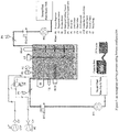
- phase I there are provided exemplary configurations for the production of directly ionized fluid as explained in "phase I” that include inline pre-treatment and post-treatment sensors configuration as shown in figure 1 , in-tank sensors configuration as shown in figure 2 , parallel flow configuration as shown in figure 3 .
- configurations for the mixing processes as explained in "phase II” that include bottom configuration as shown in figure 4 , alternative bottom configuration as shown in figure 5 , top configuration as shown in figure 6 , alternative top configuration as shown in figure 7 , parallel flow two-tank configuration as shown in figure 8 , series flow one-tank configuration as shown in figure 9 (not covered by the claimed subject matter), series flow n-tank configuration as shown in figure 10 (alternative embodiment not covered by the claimed subject matter).
- a method of treating a fluid comprising using a directly ionized second fluid resulting from "phase I" as an ionizer or an ionizing agent for ionizing the normal non-ionized first fluid in "phase II".
- using the directly ionized second fluid resulting from “phase I" as an ionizer or an ionizing agent for ionizing the normal non-ionized first fluid comprises mixing the first and second fluid in accordance with a predetermined mixing ratio as explained in "phase II".
- a method for electrostatic fluid treatment where the normal fluid is treated or ionized without being the object of direct electrostatic field.
- the present invention relates to an apparatus (the apparatus does not belong to the claimed subject matter, but will be explained herein for supporting the general understanding of the present invention) for direct electrostatic treatment of fluids
- a first fluid tank containing a normal non-ionized first fluid a second fluid tank containing a directly ionized second fluid, wherein the directly ionized second fluid is produced by applying a direct electrostatic field to the normal non-ionized first fluid while the fluid is in circulation;
- a treatment unit configured to apply the electrostatic' field to the fluid in the second fluid tank;
- a circulation pump for circulating the fluid in the second fluid tank under the influence of the magnetic/electrostatic/electromagnetic field generated from the treatment unit;
- a valve for example a proportioning valve
- a circulation conduit comprising a first conduit connecting the second fluid tank with the treatment unit; a second conduit connecting the treatment unit with the second fluid
- the treatment unit comprises an electrostatic setup for applying the electrostatic field.
- the apparatus has a plurality of sensors capable of detecting changes in the physical and chemical properties of the fluid in the second fluid tank and placed at a position such that the sensor is capable of detecting changes in physical and chemical properties of the fluid before the treatment unit and after the treatment unit.
- the apparatus has plurality of sensors capable of detecting changes in the physical and chemical properties of the fluid in the second fluid tank and provided in the interior of the second fluid tank.
- the apparatus has a plurality of actuators and sensors controlling the operating conditions of the fluid in the second fluid tank.
- the actuators and sensors are in direct connection with the second fluid tank and the circulation conduit.
- the totality of the fluid in the second fluid tank is capable of passing through the treatment unit without any bypass conduit.
- a fraction of the fluid in the second tank is capable of passing through the treatment unit and the remaining fraction is capable of passing through a bypass conduit.
- the apparatus for indirect electrostatic treatment of fluids by performing a mixing step between the normal non-ionized first fluid and the directly ionized second fluid including a) a first fluid tank containing a normal non-ionized first fluid; b) a second fluid tank containing a directly ionized second fluid; c) a third fluid tank containing a indirectly ionized third fluid, wherein the indirectly ionized third fluid is produced by mixing the directly ionized second fluid with the normal non-ionized first fluid; d) a first valve (for example first proportioning valve) for controlling the flow rate of the normal non-ionized first fluid; e) a second valve (for example second proportioning valve) for controlling the flow rate of the directly ionized second fluid; f) a plurality of actuators and sensors for controlling the mixing conditions of the indirectly ionized third fluid in the third fluid tank; g) a first conduit connecting the first fluid tank with the third fluid
- the apparatus can be adapted such that the directly ionized second fluid and the normal non ionized first fluid are mixed in the third fluid tank. In another embodiment that is not in accordance to the claimed subject matter, the apparatus can be adapted such that the directly ionized second fluid and the normal non ionized first fluid are mixed in the conduit connecting the first and second fluid tanks with the third fluid tank.
- the invention includes an apparatus (the apparatus does not belong the claimed subject matter, but is provided for supporting the general understanding of the present invention) for indirect electrostatic treatment of fluids by mixing the normal non-ionized first fluid and the directly ionized second fluid comprising a) a first fluid tank containing a normal non-ionized first fluid; b) a second fluid tank containing a directly ionized second fluid; c) a third fluid tank containing a third indirectly ionized fluid, wherein the third indirectly ionized fluid is produced by mixing the directly ionized second fluid with the normal non-ionized first fluid; d) a first conduit connecting the first fluid tank with the second fluid tank; e) a second conduit connecting the second fluid tank with the third fluid tank; f) a valve (for example proportioning valve) for controlling the flow rate of the normal non-ionized first fluid; and g) a plurality of actuators and sensors for controlling the mixing conditions of the third indirectly ionized fluid in the third fluid tank.
- the apparatus is adapted such that the directly ionized second fluid and the normal non ionized first fluid are mixed in the second fluid tank. In yet another embodiment that is not covered by the claimed subject matter, the apparatus is adapted such that the directly ionized second fluid and the normal non ionized first fluid are mixed in a plurality of tanks connected in series.
- An aspect of the invention is related to a method of direct electrostatic treatment of fluids including a) providing a volume of a normal non-ionized first fluid to a second fluid tank; b) applying a direct electrostatic/ field to the normal non-ionized first fluid; c) circulating the normal non-ionized fluid in the second fluid tank through a treatment unit that outputs its flow back to the second fluid tank for a controlled time and/or controlled flow rate, with optional intermittent circulation cycles, to produce a directly ionized second fluid; d) measuring the properties of the directly ionized second fluid in the second fluid tank using at least one sensor to obtain at least one measurement; e) adjusting the operating conditions of the directly ionized second fluid in the second fluid tank based on the obtained measurement: and f) optionally performing mixing process of the directly ionized second fluid in the second fluid tank using a mixer or a mixing pump according to a controlled mixing duty cycle.
- the method of direct electrostatic treatment of fluids according to the invention is such that the totality of the fluid in the second fluid tank is passing through the treatment unit without any bypass conduit.
- the method of direct magnetic/electrostatic/electromagnetic treatment of fluids according to the invention is such that a fraction of the fluid in the second fluid tank is passing through the treatment unit and the remaining fraction is passing through a bypass conduit.
- the method of direct electrostatic treatment of fluids involves the process of applying electrostatic fields on the directly ionized fluid within the treatment unit while the fluid is under controlled circulation environments.
- the circulation process might be controlled using the common on-off mode of control where the circulation process is completely turned on for certain period, and completely turned off for certain period.
- the ratio between the time of turning on the circulation process to the overall on and off time within one complete cycle is defined as the circulation duty cycle.
- This circulation duty cycle might have values from 0% (totally off for certain time) to 100% (totally on for certain time).
- the method of direct electrostatic treatment of fluids also includes at least one sensor that is configured to control the temperature, pressure, flow rate, circulation duty cycle, mixing duty cycles, level and/or volume of the fluid in the second tank.
- the mixing process might be controlled using the common on-off mode of control where the mixing process is turned on for certain period, and turned off for certain period.
- the ratio between the time of turning on the mixing process to the overall on and off time within one complete cycle is defined as the mixing duty cycle.
- This mixing duty cycle might have values from 0% (totally off for certain time) to 100% (totally on for certain time).
- the flow rate and the circulation duty cycles of the directly ionized second fluid are fluid and application dependent.
- the controlled variables can be tuned and controlled according to certain desired values that might have a constant or a variable time profile based on feedback of at least one sensor.
- the sensors used in this regard might be inline conductivity sensors, inline viscosity sensors, inline density sensors, inline TDS sensors, inline PH sensors, or any other type of sensors that is mostly related to the dominant physical and chemical properties of the fluid to be ionized. This means that the sensors selection process is fluid dependent. Once the proper sensors are selected, the actions to be taken by the control system depend the measured values of these sensors and these values and actions are application dependent.
- this selection process will depend on the fluid to be ionized (say water for example).
- the fluid to be ionized say water for example.
- the changes in the conductivity might be for values lower than the reference values of the normal non-ionized fluid, or for higher values than the reference values of the normal non-ionized fluid.
- the selection process for the two mentioned scenarios will depend on our application and our understanding of the use of the second ionized fluid in that application and will not be fluid dependent.
- the directly ionized second fluid if the directly ionized second fluid is stored, the quality, properties and features of the stored directly ionized second fluid are preserved. This means that if the directly ionized second fluid is used directly in the proper application or stored for later use, the goals and objectives of using it as a magnetizer for the normal non-ionized first fluid will be maintained. For example, if diesel is ionized and used after three or four years of its production, then it will give the same results as if it is used immediately in the proper application.
- the method of indirect electrostatic treatment of fluids includes a step of mixing a directly ionized second fluid and a normal non-ionized first fluid in accordance with a predetermined mixing ratio to generate a third indirectly ionized fluid wherein the third indirectly ionized fluid is ionized indirectly from the directly ionized second fluid.
- the directly ionized second fluid can be used as an ionizer or an ionizing agent for ionizing the normal non-ionized first fluid.
- the third indirectly-ionized fluid is not subjected to any direct magnetic/electrostatic/electromagnetic treatment. The mixing ratio between the directly ionized second fluid and the normal non-ionized first fluid is application dependent and fluid dependent.
- the mixing process between normal water and ionized water for the purpose of concrete strength improvement will have a mixing ratio that is different from the mixing process between normal diesel and ionized diesel for the purpose of combustion improvement, even though the operational conditions (temperature, pressure, level, volume, flow rate, circulation duty cycles, mixing duty cycles) for the production of the directly ionized fluid in both cases are similar.
- the method of indirect electrostatic treatment of fluids includes a) a first step of depositing the directly ionized second fluid in the bottom of a mixing vessel; and b) a second step of depositing the normal non-ionized first fluid on the top of the directly ionized second fluid; and c) repeating the above first and second steps once or a plurality of times.
- the method of indirect electrostatic treatment of fluids includes a) a first step of depositing the normal non-ionized first fluid in the bottom of a mixing vessel; b) a second step of depositing the directly ionized second fluid on the top of the normal non-ionized first fluid; and c) repeating the above first and second steps once or plurality of times.
- the method of indirect /electrostatic treatment of fluids includes a) providing a first vessel for receiving the normal non- ionized first fluid; b) providing a second vessel for receiving the directly ionized second fluid; and c) providing a third vessel for receiving the third indirectly-ionized fluid that is in fluidic connection with the first and second vessels for simultaneously receiving a first controlled flow of the normal non-ionized first fluid and a second controlled flow of the directly ionized second fluid.
- the method of indirect electrostatic treatment of fluids includes a) providing a first vessel for receiving the normal non-ionized first fluid; b) providing a second smaller vessel for receiving the directly ionized second fluid; and c) providing a third vessel for receiving the third indirectly-ionized fluid, where the second small vessel receives a controlled flow of the normal non-ionized first fluid from the first vessel and outputs a flow of third indirectly-ionized fluid for the third vessel comprising the normal non-ionized first fluid and the directly ionized second fluid.
- the method of indirect electrostatic treatment of fluids also includes a) providing a first vessel for receiving the normal non-ionized first fluid; b) providing a plurality of smaller vessels that are connected in series for receiving the directly ionized second fluid, and c) providing a third vessel for receiving the third indirectly-ionized fluid, where the first small vessel receives a controlled flow of the normal non-ionized first fluid from the first vessel and the plurality of small vessels output a flow of third indirectly-ionized fluid for the third fluid vessel.
- the method of indirect electrostatic treatment of fluids can be such that the first fluid is the normal non-ionized fluid that does not pass through any direct magnetic/electrostatic/electromagnetic field, the second fluid is the directly ionized fluid that undergoes direct electrostatic treatment, and the third indirectly-ionized fluid, resulting from the mixing process between the normal non-ionized first fluid and the directly ionized second fluid, is ionized or treated indirectly from the directly ionized second fluid, and the third indirectly-ionized fluid becomes totally treated.
- the method of indirect electrostatic treatment of fluids can be such that the directly ionized second fluid and the third indirectly-ionized fluid can be used immediately in the proper application or can be stored for later use.
- indirectly ionized diesel is used after three or four years of its production, then it will give the same results as if it is used immediately in the proper application.
- the production of the directly ionized second fluid can be spatially and temporally decoupled from the production of the third indirectly ionized fluid.
- the treatment plants can be such that they are not in the same location as the mixing plants.
- the third indirectly-ionized fluid can have better characteristics than the directly ionized second fluid and the normal non-ionized first fluid whenever used in the application if properly mixed according to the optimal mixing ratio and mixing procedure.
- the indirectly ionized third fluid can be used as an ionizer or ionizing agent for the normal non-ionized first fluid for more than one time depending on the mixing ratio and mixing procedure between the normal non-ionized first fluid and the directly ionized second fluid.
- we might produce the third fluid by mixing the normal non-ionized first fluid and the directly ionized second fluid according to a mixing ratio of 100:1 (100 liter of the normal non-ionized first fluid and 1 liter of the directly ionized second fluid).
- this third fluid as ionizer or ionizing agent for the normal non-ionized first fluid (instead of the second fluid) by mixing the normal non-ionized first fluid and the third indirectly ionized fluid according to a mixing ratio of 1000:1 (1000 liter of the normal non-ionized first fluid and 1 liter of the third indirectly ionized fluid).
- the quality, properties and features of the stored third indirectly ionized fluid are totally preserved. For example, if indirectly ionized diesel is used after three or four years of its production, then it will give the same results as if it is used immediately in the proper application,
- the directly ionized second fluid and the normal non-ionized first fluid used in the mixing process can be of similar chemical composition or have a different chemical composition.
- normal non-ionized gasoline with a directly ionized gasoline
- normal non-ionized gasoline with a directly ionized diesel
- normal non-ionized kerosene with a directly ionized diesel and so on.
- the method of indirect electrostatic fluid treatment comprises the following three phases that are decoupled in time and space:
- the previously mentioned fluid treatment process has one, more or all of the following controlling parameters that are fluid dependent and application dependent:
- the principal characteristics of the present invention may comprise one, more or all of:
- the directly ionized water is used as an ionizing agent or ionizer for the normal faucet water.
- the directly ionized water is mixed according to the bottom mixing configuration with the normal faucet water (with a TDS of 650 ppm) with a mixing ratio of 1000 ppm (1 ml of directly ionized water is mixed with 1 liter of normal faucet water) where the directly ionized water is added at the bottom of the mixing vessel, and the normal water is added after that.
- the resultant mixed or indirectly-ionized water is then used for making and curing of concrete cubes according to EN123903, ASTM-C143, ASTM-C1077, and other related standard with compression strength of 250 N/mm 2 .
- the crushing strength of the trial cubes was measured at different ages of the cubes staring from day 2 to day 28 from the casting date.
- the results of compression strength for the reference normal water, directly ionized water, and the resultant mixed or indirectly-ionized water are shown in table 2.
- the directly ionized diesel is used as an ionizing agent or ionizer for the normal commercial Jordanian diesel.
- the directly ionized diesel is mixed according to the top mixing configuration with the normal commercial Jordanian diesel with a mixing ratio of 100 ppm (0.1 ml of directly ionized diesel is mixed with 1 liter of normal commercial Jordanian diesel) where the normal commercial Jordanian diesel is added at the bottom of the mixing vessel, and the directly ionized diesel is added at its top.
- the resultant mixed or indirectly-ionized diesel is then used as the diesel fuel for the "International Company for Ceramic Production" in Mafraq governate, Jordan for a period of three months.
- the average fuel consumption for the factory using the reference normal commercial diesel, and the resultant mixed or indirectly-ionized diesel are shown in table 4.
- Table 4 Average fuel consumption for the ceramic factory using the reference normal commercial diesel, and the resultant mixed or indirectly- ionized diesel.
- Reference diesel consumption for a period of three months indirectly-ionized diesel consumption for a period of three months Percentage of Fuel saving 1.15-1.2 liter/m 2 of produced ceramic 0.95 -1 liter/m 2 of produced ceramic 17%
- the directly ionized gasoline is used as an ionizing agent or ionizer for the normal commercial Jordanian gasoline.
- the directly ionized gasoline is mixed according to the two following stages of mixing:-
- Second stage Where top mixing configuration between the normal commercial Jordanian gasoline and the mixed or indirectly ionized gasoline that result from the first stage with a mixing ratio of 1000 ppm (1 ml of mixed or indirectly ionized gasoline resulting from the first stage is mixed with 1 liter of normal commercial Jordanian gasoline) where the normal commercial Jordanian diesel is added at the bottom of the mixing vessel, and the mixed or indirectly ionized gasoline that result from the first stage is then added at its top.
- the resultant two-stage mixed or indirectly- ionized gasoline is then used as the gasoline fuel for different vehicles that operates on gasoline 90 grade.
- the average fuel consumption for the vehicles using the reference normal commercial gasoline, and the resultant two-stage mixed or indirectly-ionized gasoline are shown in table 6.
- the vehicle routes, speeds, and other conditions are kept under the same operating conditions.
- Table 6 Average mileage for different vehicle brands using the reference normal commercial gasoline, and the resultant two-stage mixed gasoline.
- the directly ionized Saudi Arabia diesel is used as an ionizing agent or ionizer for the normal commercial Jordanian diesel.
- the directly ionized diesel is mixed according to the top mixing configuration with the normal commercial Jordanian diesel with a mixing ratio of 1000 ppm (1 ml of directly ionized diesel is mixed with 1 liter of normal commercial Jordanian diesel) where the normal commercial Jordanian diesel is added at the bottom of the mixing vessel, and the directly ionized diesel is added at its top. This mixing process took place in January 2009 immediately after the production of the directly ionized diesel.
- the resultant mixed or indirectly-ionized diesel is divided into two parts; the first part was used immediately in pick-ups and diesel generators for the purpose of testing the immediate effect of the indirectly-ionized diesel.
- the second part was stored in storage tanks for later use for the purpose of testing the storage effect of the indirectly- ionized diesel.
- the average fuel consumption for the pick-ups using the reference normal commercial diesel, and the resultant mixed or indirectly-ionized diesel are shown in table 8.
- the pick-ups routes, speeds, and other conditions arc kept under the same operating conditions.
- the average fuel consumption for the diesel generators using the reference normal commercial diesel and the resultant mixed or indirectly-ionized diesel are shown in table 9.
- the loading and the operating conditions of the diesel generators are kept the same while performing this test.
- Table 8 Average mileage for different pick-up brands using the reference normal commercial diesel and the indirectly-ionized diesel where the indirectly-ionized diesel is used immediately without storage.
- Table 9 Average fuel consumption for different diesel generator brands using the reference normal commercial diesel and the indirectly-ionized diesel where the indirectly-ionized diesel is used immediately without storage.
- the second part of the indirectly-ionized diesel that was stored in storage tanks was tested after four years of storage in order to check its validity and functionality.
- the same pick-ups and diesel generators were used again in this test.
- the average fuel consumption for the pick-ups using the reference normal commercial diesel, and the 4-year stored indirectly-ionized diesel are shown in table 10.
- the pick-ups routes, speeds, and other conditions are kept under the same operating conditions.
- the average fuel consumption for the diesel generators using the reference normal commercial diesel and the 4-ycar stored indirectly-ionized diesel are shown in table 1 1 ,
- the loading and the operating conditions of the diesel generators are kept the same while performing this test.
- Table 10 Average mileage for different pick-up brands using the reference normal commercial diesel and the indirectly-ionized diesel where the indirectly-ionized diesel is used after four years of storage.
- number Pick-up brand Year of production Reference fuel mileage (km/L) mixed fuel mileage (km/L) Fuel saving percentage (%) 1 Toyota 1995 11.6 14.3 18.9 2 Nissan 2005 12.8 14.2 9.9 3 Isuzu 2007 13.7 15.7 12.7 4 Mitsubishi 2000 12.1 15.2 20.4
- Table 11 Average fuel consumption for different diesel generator brands using the reference normal commercial diesel and the indirectly-ionized diesel where the indirectly-ionized diesel is used after four years of storage.
- Fuel saving percentage (%) 1 Marquis 2005 0.46 0.35 23.9 2 epsilon 2007 0.43 0.34 20.9 3 United power 2006 0.38 0.29 23.7
- the directly ionized diesel that is stored for four years as an ionizing agent or ionizer for the normal commercial Jordanian diesel.
- the 4-years stored directly ionized diesel is mixed according to the top mixing configuration with the normal commercial Jordanian diesel with a mixing ratio of 1000 ppm (1 ml of 4-years stored directly ionized diesel is mixed with 1 liter of normal commercial Jordanian diesel) where the normal commercial Jordanian diesel is added at the bottom of the mixing vessel, and the 4-years stored directly ionized diesel is added at its top.
- the average fuel consumption for the pick-ups using the reference normal commercial diesel, and the mixed or indirectly-ionized diesel are shown in table 12.
- the pick-ups routes, speeds, and other conditions are kept under the same operating conditions.
- the average fuel consumption for the diesel generators using the reference normal commercial diesel and the resultant mixed or indirectly- ionized diesel are shown in table 13.
- the loading and the operating conditions of the diesel generators are kept the same while performing this test.
- Table 12 Average mileage for different pick-up brands using the reference normal commercial diesel and the indirectly-ionized diesel where the directly-ionized diesel is used after four years storage.
- MLA900 conductivity sensor (with a measurement range 0-2000 ps/m) was used to measure the conductivity of the mixed or indirectly-ionized that was produced according to different mixing concentrations between the directly ionized diesel and the normal commercial Jordanian diesel.
- Table 15 conductivity measurements of the mixed or indirectly-ionized diesel using the top and bottom mixing configurations at different mixing ratios for two different testing dates.
- the directly ionized diesel is used as an ionizing agent or ionizer for the normal commercial Jordanian gasoline.
- the directly ionized diesel is mixed according to the top mixing configuration with the normal commercial Jordanian gasoline with a mixing ratio of 100 ppm (0.1 ml of directly ionized diesel is mixed with 1 liter of normal commercial Jordanian gasoline) where the normal commercial Jordanian gasoline is added at the bottom of the mixing vessel, and the directly ionized diesel is added at its top.
- the resultant mixed or indirectly-ionized gasoline is then used as the gasoline fuel for different vehicles that operates on gasoline 90 grade.
- the average fuel consumption for the vehicles using the reference normal commercial gasoline, and the resultant mixed or indirectly-ionized gasoline are shown in table 17.
- the vehicle routes, speeds, and other conditions are kept under the same operating conditions. This testing process took place in February 2014.
- Table 17 Average mileage for different vehicle brands using the reference normal commercial gasoline, and the resultant mixed gasoline.
- the applications might include, but not limited to, all applications of the direct electrostatic treatment of fluids such as water treatment for plant growth improvement, water treatment for scaling prevention, water treatment for salinity reduction, water treatment for health aspects, water treatment for construction, fuel (diesel, gasoline, jet fuel, fuel oil, crude oil, etc.) treatment for combustion efficiency improvement and exhaust emission reductions.
- fluids such as water treatment for plant growth improvement, water treatment for scaling prevention, water treatment for salinity reduction, water treatment for health aspects, water treatment for construction, fuel (diesel, gasoline, jet fuel, fuel oil, crude oil, etc.) treatment for combustion efficiency improvement and exhaust emission reductions.
Description
- The present invention pertains generally to the field of /electrostatic treatment of fluids, and more specifically to a method for electrostatic treatment of fluids that consists three separate and decoupled phases in both time and space. In the first phase (treatment phase), a field based on permanent magnets setup, or electrostatic setup, or electromagnetic setup is applied to a working fluid under controlled time and/or flow rate circulation process to obtain the directly ionized fluid that might be subjected to storage before being used in the second phase. In the second phase (mixing phase), the directly ionized fluid is used as an ionizer or an ionizing agent for ionizing indirectly the normal non-ionized fluid by mixing the directly ionized fluid and normal non-ionized fluid in accordance with a predetermined mixing ratio and mixing method between the directly ionized fluid and normal non-ionized working fluid. In the third phase (usage phase), the resultant mixed or indirectly-ionized fluid is used in the proper application directly or stored in a storage tank for later use. According to the embodiments of the invention, the three phases of the proposed method (treatment, mixing, and usage) are decoupled from each other completely in space and time. This means that the present invention achieves two types of decoupling between its phases:-
- a. Spatial decoupling. There is no need for the treatment process used in the first phase to be in the same location of the mixing process used in the second phase as in the case of all prior arts.
- b. Temporal decoupling. There is no need for simultaneous and synchronous production of the directly ionized fluid produced from the first phase and the mixed fluids produced in the second phase as in the case of all prior arts.
- Magnetohydrodynamics (MHD) (magneto fluiddynamics or hydro magnetics) is the scientific discipline that studies the dynamics of electrically conducting fluids under the effect of magnetic fields. MHD is derived from "magneto" meaning magnetic field, and "hydro" meaning fluid, and "dynamics" meaning movement or motion. The field of MHD was initiated by Hannes Alfven in 1942, for which he received the Nobel Prize in Physics in 1970.
- The idea of MHD is that magnetic fields can induce currents in a moving electrically-conductive fluid, which create mechanical forces on the fluid, and also change the magnetic field itself. The set of equations which describe MHD are a combination of the familiar
- Navier-Stokes equations of fluid dynamics and Maxwell's equations of electromagnetism. Research studies indicate that magnetohydrodynamic effects are responsible for the magnetic treatment of fluids.
- Magnetic treatment of fluids has been widely covered in the literature. Plenty of patents and research papers described methods or applications for the magnetic treatment of fluids. For example, more than 1 500 patents and more than 2500 research papers (according to IS I web of science) have been published regarding the magnetic treatment.
- Electrostatic treatment of fluids, on the other side, has received much less attention among the research society. For example, less than 50 papers and patents covered the electrostatic treatment of fluids according to ISI web of science. This is mainly due the risks and costs associated with electrostatic treatment of fluids where the fluid is exposed directly to electric current.
- The applications of magnetic or electrostatic treatment of fluids cover mainly water treatment and fuel treatment for different purposes. All previous applications of magnetic or electrostatic treatment of fluids focused on either 1) the direct application of magnetic/electrostatic/electromagnetic fields of various flux densities and variable geometries on the moving fluid, where the entire or the totality of the fluid should pass directly through the magnetic or the electromagnetic field in order to be treated. This direct treatment fact is the hidden obstacle for the limited popularity of the magnetic treatment since it leads to effective treatment only in the initial phases of installation of magnetic treatment devices, and generally ineffective treatment in the later stages. 2) or the direct application of magnetic/electrostatic/electromagnetic fields of various flux densities and variable geometries on portions of the fluid, while the remaining portion of the fluid is kept untreated and is therefore mixed instantaneously and immediately with the treated volume of the fluid. This instantaneous and immediate mixing process might occur in one of three places:- 1) within the treatment unit 2) within an external tank 3) or within a pipe connection utilizing a bypass conduit or using a three way valve.
- In this regard, patent
JP62007789A WO97/01702A WO 92/ 16460 - Patents
EP0200710A2 andUS4734202 introduce a dual treatment method for water conditioning that subjects the water to magnetic and oligodynamic treatment where the water flows upwardly and has a flow rate which is adjusted (by the control of the bypass conduit) so that the oligodynamically active metal pieces remains approximately in suspension while moving back and forth. The two patents use permanent magnet setups in 2D configurations where immediate mixing process within a pipe connection take place to control the flow across the treatment unit only, and does not have the purpose of intentional mixing. In addition to that, no recirculation process across the treatment unit is performed with only single passage of the fluid across the treatment unit. - A deliberate immediate mixing between the untreated fluid and the treated fluid is provided in
US4320003A where a device is proposed for the magnetic treatment of water to reduce and prevent the build-up of scale in the pipes and vessels through which the water flows by subjecting the water to flow in two parallel paths through the magnetic conditioner, whereby a portion of the fluid flows through the treatment chamber and is treated by the magnetic field, while the remainder of the fluid flows through the bypass chamber that is not subjected to the magnetic field. The device is used in water systems wherein a major portion of the water is recirculated continuously through the conditioner so that only a small portion of the water needs to be treated. The patent uses permanent magnet setups in 2D configurations and the aim of mixing was to maintain the operational conditions such as flow rates and pressures without affecting the magnetic treatment in water systems where a major portion of water is recirculated continuously. The immediate mixing process takes place within the treatment unit to eliminate the use of external bypass conduit. - In
US5534156 , A method for magnetic treatment of water is presented that kills microorganisms in water systems and reservoirs by removing a volume of the water containing microorganisms, subjecting it to magnetic field, and then returning the treated water immediately back the water system through a pump. The invention proposed two treatment methods including the batch treatment and the injection treatment wherein the greater the ratio of the treated water to untreated water, the greater the effectiveness of the treatment. The patent uses permanent magnet setups in 2D configurations and the aim of mixing was to maximize the ratio of the treated water with respect of the untreated water in order to improve the effectiveness of the treatment to kill microorganisms in water. The immediate mixing process takes place within an external tank using a circulation system with a pump. - A method for High frequency electromagnetic field treatment (microwave irradiations) of multiphase fluid comprising an aqueous phase and fluid hydrocarbon is covered in
EP1970109A1 . The method is used for separating a multiphase fluid comprising an aqueous phase dispersed in a fluid hydrocarbon phase into its components, by passing the multiphase fluid through a high frequency microwave irradiations within therange 1 MHz to 10GHz, wherein the aqueous phase of the multiphase fluid is rapidly and selectively heated, for an exposure time of less than 5 seconds with a power density in the aqueous phase of at least 105W/m3. The irradiated multiphase fluid is then passed to a separator wherein the multiphase fluid is separated into its components. According to the embodiments of the invention, the temperature differential between the two phases achieved by microwave irradiations is at least 20°C wherein the temperature of the aqueous phase is at least 50°C. The immediate mixing process takes place within an external tank using a circulation system with a pump. According to the invention, a portion of the fluid to be treated is recycled one or more additional cycles of treatment, and the treated volume might be mixed immediately with untreated volume using either batch treatment or injection treatment. - The most recent patents that utilize immediate mixing process within an external tank using a pump are given in patents
WO2011/086522A1 andUS2012/0305383A1 . The cited invention utilizes a dual treatment methodology based on ultrasound treatment and high frequency Electromagnetic field treatment with the goal of increasing the yield of the more valuable light hydrocarbons from the treated crude oil and petroleum products residuum. A method for treatment of crude oil and petroleum products is introduced based on a two stage treatment process, by subjecting the fluid to be treated to ultrasound vibrations in the first stage, and to high frequency electromagnetic field in the second stage, wherein the high frequency electromagnetic field comprises a component generated from the ultrasound stage, and another component from an external current source that operates at one or more frequencies in the range from 1 GHz to 15GHz at a power of no more than 1W. According to the embodiments of the invention, the intensity of the ultrasound vibrations is lower than 1MW/m2 while the frequency of the acoustic vibrations may be between 20Hz to 200 KHz. The ultrasound treatment may be carried out using ultrasound vibrations at a single frequency or over a number of frequencies within the range. According to the invention, a portion of the fluid to be treated is recycled one or more additional cycles of treatment, and the treated volume might be mixed immediately with untreated volume. The immediate mixing process takes place within an external tank using a circulation system with a pump. - Regarding the electrostatic water treatment,
US4545887 disclosed an electrostatic electrode that is placed in a storage tank of a water system for the purpose of improving descaling performance, whileUS5591317 proposed an electrostatic field generator for water treatment that might be applied for in-line and/or in-tank applications for improving particulate dispersions and reducing scaling.US4902390 disclosed an electrostatic in-tank and/or in-line water treatment system for the purpose of reduction of bacterial counts in water systems, while inUS4012310 there was provided an electrostatic water treatment system with a control circuitry to assure the proper operation of the system. InUS4073712 , a device for treating a fluid with an electrostatic field is given for the purpose of scale prevention whether in heating applications like steam boilers or cooling applications like water chillers. A water decontamination system with electrostatic treatment and ultraviolet radiation is explained inUS5217607 to minimize inorganic and organic contaminants in water circulation system. Electrostatic fuel treatment has received much less attention among researchers. For example,US4173206 described an electrostatic fuel injector for combustion systems. It is also noted that all of the prior art patents related to electrostatic fluid treatment do not include any mixing process between the treated fluid and the untreated fluid before using the working fluid in the proper application. Other relevant prior art documents to be mentioned are for instance,WO2012/156464 , which discloses the application of magnetic or electromagnetic setups and their effects, which does not disclose electrostatic treatment of fluids, as well asKR2008 0024055 US2012/305383 A1 on the other hand also discloses direct and indirect electromagnetic treatment of fluids, whereasWO92/16460 A1 - The present invention is directed to overcoming these and other deficiencies in the art.
- The common feature among all previously mentioned patents that contain mixing process between the treated fluid (using magnetic field generated from permanent magnet setups or electromagnetic field), and the untreated fluid is that the mixing process is instantaneously and immediately performed after the production of the treated fluid. This means that the production of treated fluid is coupled in time and space with the mixing process, where the production of treated fluid must be performed at the same time of mixing and in the same location (on-site treatment and mixing). This space and time coupling between the production of treated fluid and the mixing process put on the ground a major restriction where the treatment plants for the production of treated fluid must be at the same place of the mixing process.
- In addition to that, the previously mentioned patents utilizing mixing process suffers from the scaling process, where some of the cited methods cannot be scaled up for the treatment of a refinery for example, or some cannot be scaled down to cover the consumption of small consumers of few litres per unit time (day or month, etc). Furthermore, the installation of the on-site treatment units requires some modifications in the existing systems or plants to generate the instantaneously mixed fluid. This requires at least few changes in the piping systems in addition to possible shutdown of the targeted plants.
- From the previous discussion, the applicant has recognized that there is a strong need for an improved treatment method that overcomes some or all of the previous shortcomings of the previous methods and inventions that utilize the mixing process. The present invention provides a method for indirect electrostatic treatment of fluids according to
independent claim 1. The dependent claims show further examples of said method. - An object of the current invention is to provide a method (and an apparatus that is not part of the claimed subject matter, but still provided in the description to support the general understanding of the present invention) for the electrostatic treatment of fluids that consists three separate and decoupled phases in both time and space. In the first phase (treatment phase), a field based on permanent magnets setup, or electrostatic setup, or electromagnetic setup is applied to a working fluid under controlled time and/or flow rate circulation process to obtain the directly ionized fluid that might be subjected storage before being used in the second phase. In the second phase (mixing phase), the directly ionized fluid is used as an ionizer or an ionizing agent for ionizing indirectly the normal non-ionized fluid by mixing the directly ionized fluid and normal non-ionized fluid in accordance with a predetermined mixing ratio and mixing method between the directly ionized fluid and normal non-ionized working fluid. In the third phase (usage phase), the resultant mixed or indirectly-ionized fluid is used in the proper application directly or stored in a storage tank for later use. According to the embodiments of the invention, the three phases of the proposed method (treatment, mixing, and usage) are decoupled from each other completely in space and time. This means that the present invention achieves two types of decoupling between its phases:- 9.28
- a. Spatial decoupling. There is no need for the treatment process used in the first phase to be in the same location of the mixing process used in the second phase as in the case of all prior arts.
- b. Temporal decoupling. There is no need for simultaneous production of the directly ionized fluid produced from the first phase and the mixed fluids produced in the second phase as in the case of all prior arts.
- The proposed method described in this invention has the following advantages :-1) complete decoupling in time and space between the three phases of the proposed process where the production of treated fluid (phase I), the mixing process between the treated fluid and the untreated fluid (phase II), and the usage of the mixed fluid in the proper application (phase III) are completely decoupled in time and space. This means that there is no need for the treatment plants to be in the same location of the mixing plants (spatial decoupling), and there is no need for simultaneous and concurrent production of the treated and the mixed fluids (temporal decoupling) where the treated fuel is immediately and instantaneously mixed after its production as in the reported methods in literature. 2) The elimination of on-site treatment and mixing. This is a very important feature of the current invention since if the treatment plants is to be installed in an existing systems and plants, there might not be (in some cases) a space for any additional equipments to be installed in the site. 3) The ease of scaling the treatment plants from few liters of treated fluid to thousands of cubic meters of treated fluid. 4) Ease of use since there is no need for any modifications to be performed in the systems and plants. This is due to the fact that the production phase is completely decoupled from the mixing and the usage phases. The treated fluid might be packaged in containers matching the consumer requirements from bottles of less than one liter capacity to tankers of tens of cubic meters according the targeted application, preferable mixing ratio and mixing method.
- It is therefore an object of the present invention to provide a method (and an apparatus that is not part of the claimed subject matter but provided in the description for supporting the general understanding of the present invention) for electrostatic treatment of fluids that overcomes the drawbacks of existing magnetic/electrostatic/electromagnetic treatment of fluids which includes either :- 1) the direct application methods where magnetic or electromagnetic or electrostatic fields of various flux densities and variable geometries is applied on the moving fluid, where the entire or the totality of the fluid should pass directly through the magnetic/electrostatic/electromagnetic field in order to be treated, 2) the immediate and instantaneous mixing methods where direct application of electrostatic fields of various flux densities and variable geometries on portions of the fluid, while the remaining portion of the fluid is kept untreated and is therefore mixed immediately and instantaneously with the treated volume of the fluid.
- According to the embodiment of the present invention, a method (and an apparatus that is not part of the claimed subject matter but provided in the description for supporting the general understanding of the present invention) for the electrostatic treatment of fluids that consists three separate and decoupled phases in both time and space is presented. In the first phase (treatment phase), a field based on permanent electrostatic setup, is applied to a working fluid under controlled time and/or flow rate circulation process to obtain the directly ionized fluid that might be subjected to storage before being used in the second phase. In the second phase (mixing phase), the directly ionized fluid is used as an ionizer or an ionizing agent for ionizing indirectly the normal non-ionized fluid by mixing the directly ionized fluid and normal non-ionized fluid in accordance with a predetermined mixing ratio and mixing method between the directly ionized fluid and normal non-ionized working fluid. In the third phase (usage phase), the resultant mixed or indirectly-ionized fluid is used in the proper application directly or stored in a storage tank for later use. According to the embodiments of the invention, the three phases of the proposed method (treatment, mixing, and usage) are decoupled from each other completely in space and time. This means that the present invention achieves two types of decoupling between its phases:-
- a. Spatial decoupling. There is no need for the treatment process used in the first phase to be in the same location of the mixing process used in the second phase as in the case of all prior arts,
- b. Temporal decoupling. There is no need for simultaneous production of the directly ionized fluid produced from the first phase and the mixed fluids produced in the second phase as in the case of all prior arts.
- This means that according to the present invention, the first fluid is the normal non-ionized fluid that does not pass through any direct electrostatic field, while the second fluid is the directly ionized fluid that undergoes direct electrostatic treatment as explained in phase I. In the mixed or indirectly-ionized third fluid that is produced from phase II, the normal non-ionized first fluid becomes ionized and treated indirectly from the directly ionized second fluid, and the mixed or indirectly-ionized third fluid becomes totally treated and ionized. In other words, the directly ionized second fluid serves as an ionizer or an ionizing agent for ionizing the normal non-ionized first fluid.
- In the sense of the present invention, the term "directly ionized" or "directly treated" or simply "treated" referring to fluids particularly means that fluids are electrostatic treated using direct electrostatic field of certain geometry and flux density, which may be provided, for example, by a device or unit producing said respective field. Furthermore, the term "normal non-ionized", or "normal", or simply "untreated", which refers to fluids, particularly means that the respective fluids are not ionized or do or did not pass through any direct magnetic/electrostatic/electromagnetic field. Additionally, the term "mixed" or "indirectly-ionized" referring to fluids particularly means that fluids that become ionized or treated by the directly ionized fluid that serves as an ionizer or an ionizing agent, and without being under the influence of any direct electrostatic field.
- Preferably, the mixing process in phase II between the directly ionized second fluid and normal non-ionized first fluid is carried out in according with a predetermined mixing ratio, where the majority of mixture is of the normal non-ionized first fluid.
- The mixing process in phase II between the directly ionized second fluid and normal non-ionized first fluid is carried out in accordance with a predetermined mixing method.
- The treatment unit used in "phase I" for the production of the directly ionized fluid is a electrostatic setup. The electrostatic field in the treatment unit can be of any geometry (one-dimensional, two-dimensional, or three-dimensional fields) and according to the desired flux density values; the required angle between the applied field and the direction of fluid flow can be of any angle like 90, 0, 180 degrees or any other required angle.
- Preferably, the process of applying electrostatic fields of certain flux densities and geometries on the directly ionized fluid within the treatment unit in "phase I" is carried out while the fluid is under controlled time and/or flow rate circulation process.
- Preferably, the production process of the directly ionized fluid as explained in "phase I" can be achieved using the "inline pre-treatment and post-treatment sensors configuration" that comprises of: first, filling the normal non- ionized fluid in the treatment vessel from the normal fluid main supply tank; and second, performing a controlled time and/or flow rate circulation process through the treatment unit that outputs its flow back to the treatment vessel. In this configuration, a group of required sensors (that may be application and fluid dependent) are installed before and after the treatment unit that sends its sensory data to the control box in order to trace the changes in the physical and chemical quantities of the directly ionized fluid with time before and after the treatment unit for control and analysis purposes.
- Alternatively, the production process of the directly ionized fluid as explained in "phase I" can be also achieved using the "in-tank sensors configuration" that comprises of: first, filling the normal non-ionized fluid in the treatment vessel from the normal fluid main supply tank; and second, performing a controlled time and/or flow rate circulation process through the treatment unit that outputs its flow back to the treatment vessel. In this configuration, a group of required sensors (that may be application and fluid dependent) are installed in the treatment vessel that the sends its sensory data to the control box in order to trace the changes in the physical and chemical quantities of the directly ionized fluid with time for the fluid in the treatment tank.
- Alternatively, the production process of the directly ionized fluid as explained in "phase I" can be also achieved using the "parallel flow configuration" that comprises of: first, filling the normal non-ionized fluid in the treatment vessel from the normal fluid main supply tank; and second, performing a controlled time and/or flow rate circulation process where the treatment vessel simultaneously receives a first controlled flow through the treatment unit and a second controlled flow directly from the treatment vessel.
- Preferably, the mixing process as explained in "phase II" can be achieved using the bottom configuration that comprises of: first, depositing the directly ionized second fluid in the bottom of a mixing vessel; and second depositing the normal non-ionized first fluid on the top of the directly ionized second fluid. This process might be also repeated many times (alternative bottom configuration).
- Alternatively, the mixing process as explained in "phase II" can also be achieved using the top configuration that comprises of: first, depositing the normal non-ionized first fluid in the bottom of a mixing vessel; and second, depositing the directly ionized second fluid on the top of the normal non-ionized first fluid. This process might be also repeated many times (alternative top configuration).
- Alternatively (alternative embodiment not covered by the claimed subject matter), the mixing process as explained in "phase II" can also be achieved using the parallel flow two-tank configuration that comprises of: providing a first vessel for receiving the directly ionized second fluid; providing a second vessel for receiving the normal non-ionized first fluid; and providing a third vessel for receiving the mixed or indirectly-ionized third fluid that is in connection with the first and second vessels for simultaneously receiving a first controlled flow of the directly ionized second fluid and a second controlled flow of the normal non-ionized first fluid.
- Alternatively(alternative embodiment not covered by the claimed subject matter)the mixing process as explained in "phase II" can also be achieved using the series flow one-tank configuration that comprises of: providing a first vessel for receiving the normal non-ionized first fluid; providing a second smaller vessel for receiving the directly ionized second fluid, and providing a third vessel for receiving the mixed or indirectly-ionized fluid, where the second small vessel receives a controlled flow of the normal non-ionized first fluid from the first vessel and outputs a flow of mixed or indirectly- ionized fluid for the third vessel comprising the directly ionized second and normal non-ionized first fluids. This process might be also adjusted to have n-tanks in series for receiving the directly ionized second fluid where each tank is connected in series to the next tank, and the nth tank outputs a flow of mixed or indirectly-ionized fluid for the third vessel comprising the directly ionized second and normal non-ionized first fluid (series flow n-tank configuration).
- As a further aspect of the invention, there are provided exemplary configurations for the production of directly ionized fluid as explained in "phase I" that include inline pre-treatment and post-treatment sensors configuration as shown in
figure 1 , in-tank sensors configuration as shown infigure 2 , parallel flow configuration as shown infigure 3 . - As a further aspect of the invention, there are provided configurations for the mixing processes as explained in "phase II" that include bottom configuration as shown in
figure 4 , alternative bottom configuration as shown infigure 5 , top configuration as shown infigure 6 , alternative top configuration as shown infigure 7 , parallel flow two-tank configuration as shown infigure 8 , series flow one-tank configuration as shown infigure 9 (not covered by the claimed subject matter), series flow n-tank configuration as shown infigure 10 (alternative embodiment not covered by the claimed subject matter). - As another aspect of the invention, there is provided a method of treating a fluid, the method comprising using a directly ionized second fluid resulting from "phase I" as an ionizer or an ionizing agent for ionizing the normal non-ionized first fluid in "phase II".
- Preferably, using the directly ionized second fluid resulting from "phase I" as an ionizer or an ionizing agent for ionizing the normal non-ionized first fluid comprises mixing the first and second fluid in accordance with a predetermined mixing ratio as explained in "phase II".
- Further features and advantages of the present invention will become apparent from the following detailed description, taken in combination with the appended drawings.
-
Figure 1 shows an exemplary production process of the directly ionized fluid as explained in "phase I" using inline pre-treatment and post-treatment sensors configuration. -
Figure 2 shows an exemplary production process of the directly ionized fluid as explained in "phase I" using in -tank sensors configuration. -
Figure 3 shows an exemplary production process of the directly ionized fluid as explained in "phase I" using parallel flow configuration. -
Figure 4 shows an exemplary mixing process as explained in "phase II" using bottom configuration. -
Figure 5 shows an exemplary mixing process as explained in "phase II" using alternative bottom configuration. -
Figure 6 shows an exemplary mixing process as explained in "phase II" using top configuration. -
Figure 7 shows an exemplary mixing process as explained in "phase II" using alternative top configuration. -
Figure 8 shows an exemplary mixing process as explained in "phase II" using parallel flow two-tank configuration. -
Figure 9 shows an exemplary mixing process as explained in "phase IP* using series flow one-tank configuration. -
Figure 10 shows an exemplary mixing process as explained in "phase II" using series flow n-tank configuration. - In accordance with a first aspect of the present invention, there is, as an example, provided a method for electrostatic fluid treatment where the normal fluid is treated or ionized without being the object of direct electrostatic field.
- Another aspect the present invention relates to an apparatus (the apparatus does not belong to the claimed subject matter, but will be explained herein for supporting the general understanding of the present invention) for direct electrostatic treatment of fluids including a) a first fluid tank containing a normal non-ionized first fluid; b) a second fluid tank containing a directly ionized second fluid, wherein the directly ionized second fluid is produced by applying a direct electrostatic field to the normal non-ionized first fluid while the fluid is in circulation; c) a treatment unit configured to apply the electrostatic' field to the fluid in the second fluid tank; d) a circulation pump for circulating the fluid in the second fluid tank under the influence of the magnetic/electrostatic/electromagnetic field generated from the treatment unit; e) a valve (for example a proportioning valve) for controlling the flow rate of the fluid in the second fluid tank; f) a circulation conduit comprising a first conduit connecting the second fluid tank with the treatment unit; a second conduit connecting the treatment unit with the second fluid tank; and a third conduit connecting first fluid tank with the second fluid tank; i) a plurality of actuators and sensors for controlling the operating conditions of the fluid in the second fluid tank and the circulation conduit; j) a plurality of sensors capable of detecting changes in the physical and chemical properties of the fluid in the second fluid tank; and k) an optional mixer for mixing the fluid in the second fluid tank.
- In one embodiment, the treatment unit comprises an electrostatic setup for applying the electrostatic field. In another embodiment, the apparatus has a plurality of sensors capable of detecting changes in the physical and chemical properties of the fluid in the second fluid tank and placed at a position such that the sensor is capable of detecting changes in physical and chemical properties of the fluid before the treatment unit and after the treatment unit.
- In another embodiment, the apparatus has plurality of sensors capable of detecting changes in the physical and chemical properties of the fluid in the second fluid tank and provided in the interior of the second fluid tank.
- In another embodiment, the apparatus has a plurality of actuators and sensors controlling the operating conditions of the fluid in the second fluid tank. The actuators and sensors are in direct connection with the second fluid tank and the circulation conduit. In yet another embodiment, the totality of the fluid in the second fluid tank is capable of passing through the treatment unit without any bypass conduit. In yet another embodiment, a fraction of the fluid in the second tank is capable of passing through the treatment unit and the remaining fraction is capable of passing through a bypass conduit.
- In accordance with a another aspect of the present invention, there is provided the apparatus for indirect electrostatic treatment of fluids by performing a mixing step between the normal non-ionized first fluid and the directly ionized second fluid including a) a first fluid tank containing a normal non-ionized first fluid; b) a second fluid tank containing a directly ionized second fluid; c) a third fluid tank containing a indirectly ionized third fluid, wherein the indirectly ionized third fluid is produced by mixing the directly ionized second fluid with the normal non-ionized first fluid; d) a first valve (for example first proportioning valve) for controlling the flow rate of the normal non-ionized first fluid; e) a second valve (for example second proportioning valve) for controlling the flow rate of the directly ionized second fluid; f) a plurality of actuators and sensors for controlling the mixing conditions of the indirectly ionized third fluid in the third fluid tank; g) a first conduit connecting the first fluid tank with the third fluid tank; and h) a second conduit connecting the second fluid tank with the third fluid tank.
- In one embodiment that is in accordance to the claimed subject matter, the apparatus can be adapted such that the directly ionized second fluid and the normal non ionized first fluid are mixed in the third fluid tank. In another embodiment that is not in accordance to the claimed subject matter, the apparatus can be adapted such that the directly ionized second fluid and the normal non ionized first fluid are mixed in the conduit connecting the first and second fluid tanks with the third fluid tank.
- Another aspect the invention includes an apparatus (the apparatus does not belong the claimed subject matter, but is provided for supporting the general understanding of the present invention) for indirect electrostatic treatment of fluids by mixing the normal non-ionized first fluid and the directly ionized second fluid comprising a) a first fluid tank containing a normal non-ionized first fluid; b) a second fluid tank containing a directly ionized second fluid; c) a third fluid tank containing a third indirectly ionized fluid, wherein the third indirectly ionized fluid is produced by mixing the directly ionized second fluid with the normal non-ionized first fluid; d) a first conduit connecting the first fluid tank with the second fluid tank; e) a second conduit connecting the second fluid tank with the third fluid tank; f) a valve (for example proportioning valve) for controlling the flow rate of the normal non-ionized first fluid; and g) a plurality of actuators and sensors for controlling the mixing conditions of the third indirectly ionized fluid in the third fluid tank.
- In one embodiment that is not covered by the claimed subject matter, the apparatus is adapted such that the directly ionized second fluid and the normal non ionized first fluid are mixed in the second fluid tank. In yet another embodiment that is not covered by the claimed subject matter, the apparatus is adapted such that the directly ionized second fluid and the normal non ionized first fluid are mixed in a plurality of tanks connected in series.
- An aspect of the invention is related to a method of direct electrostatic treatment of fluids including a) providing a volume of a normal non-ionized first fluid to a second fluid tank; b) applying a direct electrostatic/ field to the normal non-ionized first fluid; c) circulating the normal non-ionized fluid in the second fluid tank through a treatment unit that outputs its flow back to the second fluid tank for a controlled time and/or controlled flow rate, with optional intermittent circulation cycles, to produce a directly ionized second fluid; d) measuring the properties of the directly ionized second fluid in the second fluid tank using at least one sensor to obtain at least one measurement; e) adjusting the operating conditions of the directly ionized second fluid in the second fluid tank based on the obtained measurement: and f) optionally performing mixing process of the directly ionized second fluid in the second fluid tank using a mixer or a mixing pump according to a controlled mixing duty cycle.
- In one embodiment, the method of direct electrostatic treatment of fluids according to the invention is such that the totality of the fluid in the second fluid tank is passing through the treatment unit without any bypass conduit. In another embodiment, the method of direct magnetic/electrostatic/electromagnetic treatment of fluids according to the invention is such that a fraction of the fluid in the second fluid tank is passing through the treatment unit and the remaining fraction is passing through a bypass conduit.
- In another embodiment, the method of direct electrostatic treatment of fluids involves the process of applying electrostatic fields on the directly ionized fluid within the treatment unit while the fluid is under controlled circulation environments. This means that the circulation process might be controlled using the common on-off mode of control where the circulation process is completely turned on for certain period, and completely turned off for certain period. The ratio between the time of turning on the circulation process to the overall on and off time within one complete cycle is defined as the circulation duty cycle. This circulation duty cycle might have values from 0% (totally off for certain time) to 100% (totally on for certain time).
- In another embodiment, the method of direct electrostatic treatment of fluids also includes at least one sensor that is configured to control the temperature, pressure, flow rate, circulation duty cycle, mixing duty cycles, level and/or volume of the fluid in the second tank. This means that the mixing process might be controlled using the common on-off mode of control where the mixing process is turned on for certain period, and turned off for certain period. The ratio between the time of turning on the mixing process to the overall on and off time within one complete cycle is defined as the mixing duty cycle. This mixing duty cycle might have values from 0% (totally off for certain time) to 100% (totally on for certain time).
- In another embodiment of the present invention, the flow rate and the circulation duty cycles of the directly ionized second fluid are fluid and application dependent. The controlled variables can be tuned and controlled according to certain desired values that might have a constant or a variable time profile based on feedback of at least one sensor. The sensors used in this regard might be inline conductivity sensors, inline viscosity sensors, inline density sensors, inline TDS sensors, inline PH sensors, or any other type of sensors that is mostly related to the dominant physical and chemical properties of the fluid to be ionized. This means that the sensors selection process is fluid dependent. Once the proper sensors are selected, the actions to be taken by the control system depend the measured values of these sensors and these values and actions are application dependent. For example, if we install an inline conductivity sensor in the second fluid tank, this selection process will depend on the fluid to be ionized (say water for example). After that, when we operate the direct treatment method, we will trace the changes in the conductivity in the second fluid to be ionized. The changes in the conductivity might be for values lower than the reference values of the normal non-ionized fluid, or for higher values than the reference values of the normal non-ionized fluid. The selection process for the two mentioned scenarios will depend on our application and our understanding of the use of the second ionized fluid in that application and will not be fluid dependent.
- In another embodiment of the present invention, if the directly ionized second fluid is stored, the quality, properties and features of the stored directly ionized second fluid are preserved. This means that if the directly ionized second fluid is used directly in the proper application or stored for later use, the goals and objectives of using it as a magnetizer for the normal non-ionized first fluid will be maintained. For example, if diesel is ionized and used after three or four years of its production, then it will give the same results as if it is used immediately in the proper application.
- In an additional aspect of the present invention, the method of indirect electrostatic treatment of fluids includes a step of mixing a directly ionized second fluid and a normal non-ionized first fluid in accordance with a predetermined mixing ratio to generate a third indirectly ionized fluid wherein the third indirectly ionized fluid is ionized indirectly from the directly ionized second fluid.
- In one embodiment, the directly ionized second fluid can be used as an ionizer or an ionizing agent for ionizing the normal non-ionized first fluid. In another embodiment of the present invention, the third indirectly-ionized fluid is not subjected to any direct magnetic/electrostatic/electromagnetic treatment. The mixing ratio between the directly ionized second fluid and the normal non-ionized first fluid is application dependent and fluid dependent. For example, the mixing process between normal water and ionized water for the purpose of concrete strength improvement will have a mixing ratio that is different from the mixing process between normal diesel and ionized diesel for the purpose of combustion improvement, even though the operational conditions (temperature, pressure, level, volume, flow rate, circulation duty cycles, mixing duty cycles) for the production of the directly ionized fluid in both cases are similar.
- In one embodiment, the method of indirect electrostatic treatment of fluids includes a) a first step of depositing the directly ionized second fluid in the bottom of a mixing vessel; and b) a second step of depositing the normal non-ionized first fluid on the top of the directly ionized second fluid; and c) repeating the above first and second steps once or a plurality of times.
- In another embodiment, the method of indirect electrostatic treatment of fluids includes a) a first step of depositing the normal non-ionized first fluid in the bottom of a mixing vessel; b) a second step of depositing the directly ionized second fluid on the top of the normal non-ionized first fluid; and c) repeating the above first and second steps once or plurality of times.
- In another embodiment, the method of indirect /electrostatic treatment of fluids includes a) providing a first vessel for receiving the normal non- ionized first fluid; b) providing a second vessel for receiving the directly ionized second fluid; and c) providing a third vessel for receiving the third indirectly-ionized fluid that is in fluidic connection with the first and second vessels for simultaneously receiving a first controlled flow of the normal non-ionized first fluid and a second controlled flow of the directly ionized second fluid.
- In yet another embodiment that is not covered by the claimed subject matter, the method of indirect electrostatic treatment of fluids includes a) providing a first vessel for receiving the normal non-ionized first fluid; b) providing a second smaller vessel for receiving the directly ionized second fluid; and c) providing a third vessel for receiving the third indirectly-ionized fluid, where the second small vessel receives a controlled flow of the normal non-ionized first fluid from the first vessel and outputs a flow of third indirectly-ionized fluid for the third vessel comprising the normal non-ionized first fluid and the directly ionized second fluid.
- In yet another embodiment that is not covered by the claimed subject matter, the method of indirect electrostatic treatment of fluids also includes a) providing a first vessel for receiving the normal non-ionized first fluid; b) providing a plurality of smaller vessels that are connected in series for receiving the directly ionized second fluid, and c) providing a third vessel for receiving the third indirectly-ionized fluid, where the first small vessel receives a controlled flow of the normal non-ionized first fluid from the first vessel and the plurality of small vessels output a flow of third indirectly-ionized fluid for the third fluid vessel.
- The method of indirect electrostatic treatment of fluids can be such that the first fluid is the normal non-ionized fluid that does not pass through any direct magnetic/electrostatic/electromagnetic field, the second fluid is the directly ionized fluid that undergoes direct electrostatic treatment, and the third indirectly-ionized fluid, resulting from the mixing process between the normal non-ionized first fluid and the directly ionized second fluid, is ionized or treated indirectly from the directly ionized second fluid, and the third indirectly-ionized fluid becomes totally treated.
- The method of indirect electrostatic treatment of fluids can be such that the directly ionized second fluid and the third indirectly-ionized fluid can be used immediately in the proper application or can be stored for later use. For example, if indirectly ionized diesel is used after three or four years of its production, then it will give the same results as if it is used immediately in the proper application.
- In one embodiment, the production of the directly ionized second fluid can be spatially and temporally decoupled from the production of the third indirectly ionized fluid. The treatment plants can be such that they are not in the same location as the mixing plants.
- In yet another embodiment, the third indirectly-ionized fluid can have better characteristics than the directly ionized second fluid and the normal non-ionized first fluid whenever used in the application if properly mixed according to the optimal mixing ratio and mixing procedure.
- In yet another embodiment, the indirectly ionized third fluid can be used as an ionizer or ionizing agent for the normal non-ionized first fluid for more than one time depending on the mixing ratio and mixing procedure between the normal non-ionized first fluid and the directly ionized second fluid. For example, we might produce the third fluid by mixing the normal non-ionized first fluid and the directly ionized second fluid according to a mixing ratio of 100:1 (100 liter of the normal non-ionized first fluid and 1 liter of the directly ionized second fluid). After that, we might use this third fluid as ionizer or ionizing agent for the normal non-ionized first fluid (instead of the second fluid) by mixing the normal non-ionized first fluid and the third indirectly ionized fluid according to a mixing ratio of 1000:1 (1000 liter of the normal non-ionized first fluid and 1 liter of the third indirectly ionized fluid).
- In one embodiment, if the third indirectly ionized fluid is stored, the quality, properties and features of the stored third indirectly ionized fluid are totally preserved. For example, if indirectly ionized diesel is used after three or four years of its production, then it will give the same results as if it is used immediately in the proper application,
- In yet another embodiment, the directly ionized second fluid and the normal non-ionized first fluid used in the mixing process can be of similar chemical composition or have a different chemical composition. For example, we might mix normal non-ionized gasoline with a directly ionized gasoline, normal non-ionized gasoline with a directly ionized diesel, or we might mix normal non-ionized kerosene with a directly ionized diesel and so on.
- In one embodiment, the method of indirect electrostatic fluid treatment comprises the following three phases that are decoupled in time and space:
- 1. Phase I (treatment phase). In this phase, the directly ionized second fluid is produced by:
- a. applying direct electrostatic field on the working fluid according to one, more or all of the following requirements:
- i. The required geometry of the field. We can apply one-dimensional, two-dimensional, three-dimensional fields.
- ii. The required values of the flux densities Bx, By, and Bz.
- iii. The required angle between the field and the fluid flow where the angle might be 90, 0, 180 degrees or any other required angle.
- b. Circulating the working fluid under the effect of electro static field according to the selected treatment configuration (as shown in
figures 1 to 3 ) for the required time of circulation. Controlled on-off cycles for the circulation process across the field might be used in addition to the continuous on cycles. The flow rate, temperature, pressure, and volume of the working fluid is controlled while circulating it. - c. Mixing of the fluid in the treatment vessel using either a mixer or a mixing pump according to certain controlled duty mixing cycles.
- a. applying direct electrostatic field on the working fluid according to one, more or all of the following requirements:
- 2. Phase II (mixing phase). Mix the directly ionized second fluid with the normal non-ionized first fluid at the required mixing ratio between the volume of the directly ionized second fluid and the volume of normal non-ionized first fluid according to the selected mixing configuration (as shown in
figures 4 to 10 ). The mixing process might be in one of the following forms:- a. Addition of one type of fluid at a time in a mixing vessel. This process might take one of the following configurations.
- i. Bottom configuration. Add the directly ionized second fluid at the bottom of the mixing vessel then add the normal non-ionized first fluid at the top as shown in
figure 4 . - ii. Alternative bottom configuration. Add the directly ionized second fluid at the bottom of the mixing vessel then add the normal non-ionized first fluid at the top. Then repeat this process many times as shown in
figure 5 . - iii. Top configuration. Add the normal non-ionized first fluid at the bottom of the mixing vessel then add the directly ionized second fluid at the top as shown in
figure 6 . - iv. Alternative top configuration. Add the normal non-ionized first fluid at the bottom of the mixing vessel then add the directly ionized second fluid at the top. Then repeat this process many times as shown in
figure 7 .
- i. Bottom configuration. Add the directly ionized second fluid at the bottom of the mixing vessel then add the normal non-ionized first fluid at the top as shown in
- b. Parallel flow two-tank configuration. In this scenario, we have one tank for directly ionized fluid, a second tank for the normal non-ionized fluid and a third tank for the mixed or indirectly-ionized fluid. Two valves (for example two proportioning valves) are placed at the first and second tank outputs that control the simultaneous mixing ratio between the directly ionized fluid and the normal non-ionized fluid as shown in
figure 8 . - c. Series flow one-tank configuration (not covered by the claimed subject matter). Here a simultaneous series mixing between the directly ionized fluid and the normal non-ionized fluid is performed. In this scenario, we have one tank for the directly ionized fluid, second tank for the normal non-ionized fluid and a third tank for the mixed or indirectly-ionized fluid. The normal non-ionized fluid flow from its tank that is controlled by valve (for example proportioning valve) and passes through the treated tank where the output flow of treated tank can be used immediately in the application or stored in the third mixed tank. In this case, the volume of the treated tank and the value (for example proportioning valve) opening ratio are the controlling parameters as shown in
figure 9 . - d. Series flow n-tank configuration (not covered by the claimed subject matter). Here a simultaneous series mixing between the directly ionized fluid and the normal non-ionized fluid is performed. In this scenario, we have n-tanks in series for the directly ionized fluid, a tank for the normal non-ionized fluid, and another tank for the mixed or indirectly-ionized fluid. The normal non-ionized fluid flow from its tank that is controlled by valve (for example proportioning valve) and passes through the series of treated tanks where the output flow of last treated tank can be used immediately in the application or stored in the third mixed tank. In this case, the volume of the treated tanks and the value (for example proportioning valve) opening ratio are the controlling parameters as shown in
figure 10 .
- a. Addition of one type of fluid at a time in a mixing vessel. This process might take one of the following configurations.
- 3. Phase III (usage phase). Use the mixed or indirectly-ionized fluid in the proper application. In this case, we have two scenarios. In the first scenario, the mixed or indirectly-ionized fluid is stored in the mixing tank for later use, while in the second scenario; the mixed or indirectly-ionized fluid is used immediately in the application without being stored in the mixing tank.
- In yet another embodiment, the previously mentioned fluid treatment process has one, more or all of the following controlling parameters that are fluid dependent and application dependent:
- Phase I. The production of the directly ionized fluid:
- a. The dimension and the geometry of the applied field (one-dimensional, two-dimensional, three-dimensional).
- b. The desired values of flux/current densities depending on the given dimension.
- c. The required angle between the applied field and the fluid flow where the angle might be 90 degrees (perpendicular direction), 0 degree (in the same direction), 180 degrees (in the opposite direction) or any other required angle.
- d. The required volume (level) of the directly ionized fluid.
- e. The required temperature and pressure of the directly ionized fluid.
- f. The flow rate of the fluid under the effect of the field.
- g. The required circulation time or application time of the field upon the fluid. Controlled on-off cycles for the circulation pump across the applied field might also be used in addition to the continuous on cycles.
- h. The geometry of the pipes under the treatment and their inner cross sections.
- Phase II. mixing process parameters:
- i. The volume of the normal non-ionized fluid,
- j. The volume of directly ionized fluid.
- k. The required temperature and pressure of the normal non-ionized fluid and the directly ionized fluid.
- I. The mixing ratio between the two fluids controlled by the valves (for example proportioning valves) openings whenever used.
- m. The mixing flow rates for the normal non-ionized fluid and the directly ionized fluid.
- Phase III. Mixed fluid storage or usage parameters:
n. The required temperature and pressure of the storage tank in case of storage case. - In yet another embodiment, the principal characteristics of the present invention may comprise one, more or all of:
- a. Use of directly ionized or treated fluid as an ionizer or ionizing agent for the normal non-ionized fluid.
- b. Use of the field stored in the directly ionized fluid as a treatment methodology for the normal non-ionized fluid.
- c. Use of any electrostatic setup in the preparation of the directly ionized fluid.
- d. Use of one-dimensional, two-dimensional, or three-dimensional geometries of certain flux densities in the preparation of the directly ionized fluid.
- e. The temperature, pressure, flow rate, and volume (level) of the directly ionized fluid are tuned and controlled during the production of directly ionized fluid in
phase 1 and the mixing process in phase II. - f. The temperature, pressure, flow rate, and volume (level) of the normal non- ionized fluid and the mixed or indirectly-ionized fluid are tuned and controlled during the mixing process in phase II and in the storage process in phase III.
- g. The heating or cooling element anywhere used in the figures means a heating and/or cooling system that controls the temperature of the fluid exactly as required.
- h. All of the controlling parameters of the present invention might be controlled according to inline sensors data that can be used in all phases of the proposed process. These sensors are fluid dependent and application dependent. For example in case of fuel treatment, we might have used inline conductivity, viscosity and density sensors to observe the changes in the physical parameters of the fluid. If the working fluid is water, we might use inline PH and TDS sensors or any other sensors.
- i. Use of most commonly used modes of operation regarding the angle between the applied field and the fluid flow where the angle might be 90, 0, 180 degrees or other angles.
- j. The shape of the pipe in which the fluid is flowing under the effect of the applied field which might be straight, vertical-horizontal, helical three-dimensional (spring like) shapes or any other shape,
- k. The fluid flow under the effect of the applied field during the preparation of the directly ionized fluid in phase I might be under the effect of gravitational forces in case of vertical flow or might be horizontal flow or at any angle.
- l. Use of circular, square, or rectangular cross sections of the inner core of the pipe under the effect of the applied field,
- m. The diameter of the pipe in which the fluid is flowing under the effect of the applied field might be in the micro level or the macro level or might take any value from nano size to centimeters size,
- n. The directly ionized fluid in phase I might be circulated continuously for certain period of time, or using controlled on- off cycles for the circulation process across the applied field.
- o. The mixing ratio between the directly ionized fluid and the normal non-ionized fluid generally depends on the working fluid, the operating conditions of phase I, and the application.
- p. The directly ionized fluid in phase I and the mixed or indirectly-ionized fluid in phase II might be kept at certain pressure and temperature for certain duration during their storage for later use.
- q. The normal non-ionized fluid and the directly ionized fluid have generally the same chemical structure, but might have different chemical structure. For example, treated or ionized diesel might be used as the treating agent or ionizer for gasoline fuel, treated drinking water might be used as the treating agent or ionizer for sea water.
- Normal faucet water with a TDS of 650 ppm was electrostatically treated in the treatment vessel for 1 day according to the inline pre-treatment and post-treatment sensors configuration. The used sensors are the inline TDS and inline PH sensors. The operating conditions for the production of the directly ionized water in phase I are given in Table 1.
Table 1 : operating conditions for the production of the directly ionized water in phase I. Number Operating parameter Operating value Operating unit 1 Treatment vessel pressure 5 bar 2 Circulation line pressure 10 bar 3 Treatment vessel temperature 50 C° 4 Circulation flow rate 25 Liter/hour 5 Tank volume 50 Liter 6 Tank level 100% % 7 Circulation duty cycle 50%, 2 hour on, 2 hour off % - The directly ionized water is used as an ionizing agent or ionizer for the normal faucet water. The directly ionized water is mixed according to the bottom mixing configuration with the normal faucet water (with a TDS of 650 ppm) with a mixing ratio of 1000 ppm (1 ml of directly ionized water is mixed with 1 liter of normal faucet water) where the directly ionized water is added at the bottom of the mixing vessel, and the normal water is added after that.
- The resultant mixed or indirectly-ionized water is then used for making and curing of concrete cubes according to EN123903, ASTM-C143, ASTM-C1077, and other related standard with compression strength of 250 N/mm2. The crushing strength of the trial cubes was measured at different ages of the cubes staring from
day 2 to day 28 from the casting date. The results of compression strength for the reference normal water, directly ionized water, and the resultant mixed or indirectly-ionized water are shown in table 2. - It is clear from table 2 that an improvement in the compression strength of the indirectly-ionized water is achieved as compared to reference normal water with an improvement ratio of 14% at the second day of casting, 32% at the fifth day of casting, 32% at the eighth day of casting, and 22% at the 28th day of casting.
- From the other side, the directly ionized water results in less compression strength of as compared to reference normal water with reduction percentages from 13% to 32%. This facts points out to the limitations and drawbacks of using the directly treated fluids in the applications, and shows that the solution to this problems stems from using the resultant mixed or indirectly-ionized fluids instead of the directly treated fluids.

- Commercial Jordanian diesel was magnetically treated in the treatment vessel for
2 days according to the in-tank sensors configuration. The used sensors are the conductivity, viscosity, and density sensors. The operating conditions for the production of the directly ionized diesel in phase I are given in table 3.Table 3: operating conditions for the production of the directly ionized diesel in phase I. Number Operating parameter Operating value Operating unit 1 Treatment vessel pressure -1 bar 2 Circulation line pressure 5 bar 3 Treatment vessel temperature 70 C° 4 Circulation flow rate 50 Liter/hour 5 Tank volume 500 Liter 6 Tank initial level at starting day 250 Liter 7 Tank level at 2nd day 500 Liter 8 Circulation duty cycle 50%, 1 hour on, 1 hour off % - The directly ionized diesel is used as an ionizing agent or ionizer for the normal commercial Jordanian diesel. The directly ionized diesel is mixed according to the top mixing configuration with the normal commercial Jordanian diesel with a mixing ratio of 100 ppm (0.1 ml of directly ionized diesel is mixed with 1 liter of normal commercial Jordanian diesel) where the normal commercial Jordanian diesel is added at the bottom of the mixing vessel, and the directly ionized diesel is added at its top.
- The resultant mixed or indirectly-ionized diesel is then used as the diesel fuel for the "International Company for Ceramic Production" in Mafraq governate, Jordan for a period of three months. The average fuel consumption for the factory using the reference normal commercial diesel, and the resultant mixed or indirectly-ionized diesel are shown in table 4.
Table 4: Average fuel consumption for the ceramic factory using the reference normal commercial diesel, and the resultant mixed or indirectly- ionized diesel. Reference diesel consumption for a period of three months indirectly-ionized diesel consumption for a period of three months Percentage of Fuel saving 1.15-1.2 liter/m2 of produced ceramic 0.95 -1 liter/m2 of produced ceramic 17% - In addition to the 17% fuel saving that was reported from the ceramic factory, a reduction in the soot emissions was observed from the furnace operators.
- Commercial Jordanian gasoline of grade 90 was electromagnetically treated in the treatment vessel for 12 hours according to the parallel flow configuration. The used sensors are the conductivity and density sensors. The operating conditions for the production of the directly ionized gasoline in phase I are given in table 5.
Table 5: operating conditions for the production of the directly ionized gasoline in phase 1.Number Operating parameter Operating value Operating unit 1 Treatment vessel pressure 0 (atmospheric pressure) bar 2 Circulation line pressure 3 bar 3 Treatment vessel temperature 25 (room temperature) C° 4 Circulation flow rate 2 Liter/hour 5 Tank volume 50 Liter 6 Tank initial level at starting day 50 Liter 7 Circulation duty cycle 100%, Continuous on % 8 Bypass fluid percentage 50% % - The directly ionized gasoline is used as an ionizing agent or ionizer for the normal commercial Jordanian gasoline. The directly ionized gasoline is mixed according to the two following stages of mixing:-
- First stage. Where alternative bottom mixing configuration between the normal commercial Jordanian gasoline and the directly ionized gasoline with a mixing ratio of 50000 ppm (50 ml of directly ionized gasoline is mixed with 1 liter of normal commercial Jordanian gasoline) where the overall quantity of mixed gasoline is mixed at 10 equal stages with the directly ionized gasoline added at the bottom of the mixing vessel, and then the normal commercial Jordanian gasoline is added at its top, and so on for 10 times.
- Second stage. Where top mixing configuration between the normal commercial Jordanian gasoline and the mixed or indirectly ionized gasoline that result from the first stage with a mixing ratio of 1000 ppm (1 ml of mixed or indirectly ionized gasoline resulting from the first stage is mixed with 1 liter of normal commercial Jordanian gasoline) where the normal commercial Jordanian diesel is added at the bottom of the mixing vessel, and the mixed or indirectly ionized gasoline that result from the first stage is then added at its top.
- The resultant two-stage mixed or indirectly- ionized gasoline is then used as the gasoline fuel for different vehicles that operates on gasoline 90 grade. The average fuel consumption for the vehicles using the reference normal commercial gasoline, and the resultant two-stage mixed or indirectly-ionized gasoline are shown in table 6. The vehicle routes, speeds, and other conditions are kept under the same operating conditions.
Table 6: Average mileage for different vehicle brands using the reference normal commercial gasoline, and the resultant two-stage mixed gasoline. Number Vehicle brand Year of production Reference fuel mileage (km/L) two-stage mixed fuel mileage (km/L) Fuel saving percentage (%) 1 Nissan-Sunny 2008 15.1 18 19.2 2 Hyundai-Accent 2005 16.3 19.2 17.8 3 Chevrolet-Aveo 2013 14.8 16.3 10.1 4 Kia-Sportage 2012 11.2 12.8 14.3 5 Mercedes-E200 2010 10.7 12.4 15.9 - In addition to the 10%-20% fuel saving that was reported from the owners of the vehicles, an increase in the power of the engine was reported with about 20% increase of the reference power of the vehicle.
- Commercial Saudi Arabia diesel was magnetically treated in the treatment vessel for 2 days according to the inline pre-treatment and post-treatment sensors configuration. This treatment process took place in January 2009. The used sensors are the inline conductivity, viscosity, and density sensors. The operating conditions for the production of the directly ionized diesel in phase I are given in table 7.
Table 7: operating conditions for the production of the directly ionized diesel in phase I. Number Operating parameter Operating value Operating unit 1 Treatment vessel pressure 0 (atmospheric pressure) bar 2 Circulation line pressure 5 bar 3 Treatment vessel temperature 10 C° 4 Circulation flow rate 10 Liter/hour 5 Tank volume 200 Liter 6 Tank initial level at starting day 100 Liter 7 Tank level at 2nd day 200 Liter 8 Circulation duty cycle Continuous on 100% - The directly ionized Saudi Arabia diesel is used as an ionizing agent or ionizer for the normal commercial Jordanian diesel. The directly ionized diesel is mixed according to the top mixing configuration with the normal commercial Jordanian diesel with a mixing ratio of 1000 ppm (1 ml of directly ionized diesel is mixed with 1 liter of normal commercial Jordanian diesel) where the normal commercial Jordanian diesel is added at the bottom of the mixing vessel, and the directly ionized diesel is added at its top. This mixing process took place in January 2009 immediately after the production of the directly ionized diesel.
- The resultant mixed or indirectly-ionized diesel is divided into two parts; the first part was used immediately in pick-ups and diesel generators for the purpose of testing the immediate effect of the indirectly-ionized diesel. The second part was stored in storage tanks for later use for the purpose of testing the storage effect of the indirectly- ionized diesel. The average fuel consumption for the pick-ups using the reference normal commercial diesel, and the resultant mixed or indirectly-ionized diesel are shown in table 8. The pick-ups routes, speeds, and other conditions arc kept under the same operating conditions. The average fuel consumption for the diesel generators using the reference normal commercial diesel and the resultant mixed or indirectly-ionized diesel are shown in table 9. The loading and the operating conditions of the diesel generators are kept the same while performing this test.
Table 8: Average mileage for different pick-up brands using the reference normal commercial diesel and the indirectly-ionized diesel where the indirectly-ionized diesel is used immediately without storage. number Pick-up brand Year of production Reference fuel mileage (km/L) mixed fuel mileage (km/L) Fuel saving percentage (%) 1 Toyota 1995 12.1 15.3 20.9 2 Nissan 2005 13.3 14.8 10.1 3 Isuzu 2007 14.2 16.5 13.9 4 Mitsubishi 2000 12.7 15.6 18.6 Table 9: Average fuel consumption for different diesel generator brands using the reference normal commercial diesel and the indirectly-ionized diesel where the indirectly-ionized diesel is used immediately without storage. number Diesel generator brand Year of production Reference fuel consumption (L/kW) mixed fuel consumption (L/kW) Fuel saving percentage (%) 1 Marquis 2005 0.46 0.35 23.9 2 epsilon 2007 0.43 0.34 20.9 3 United power 2006 0.38 0.29 23.7 - From tables 8 and 9, it is obvious that a fuel saving within the range 10%- 20% was achieved for the pick-ups, while a fuel saving within the range 20%-25% was achieved for the diesel generators. In addition to that, a reduction in the soot emission was also achieved using the indirectly-ionized diesel as compared with the reference normal commercial diesel.
- The second part of the indirectly-ionized diesel that was stored in storage tanks was tested after four years of storage in order to check its validity and functionality. The same pick-ups and diesel generators were used again in this test. The average fuel consumption for the pick-ups using the reference normal commercial diesel, and the 4-year stored indirectly-ionized diesel are shown in table 10. The pick-ups routes, speeds, and other conditions are kept under the same operating conditions. The average fuel consumption for the diesel generators using the reference normal commercial diesel and the 4-ycar stored indirectly-ionized diesel are shown in table 1 1 , The loading and the operating conditions of the diesel generators are kept the same while performing this test.
Table 10: Average mileage for different pick-up brands using the reference normal commercial diesel and the indirectly-ionized diesel where the indirectly-ionized diesel is used after four years of storage. number Pick-up brand Year of production Reference fuel mileage (km/L) mixed fuel mileage (km/L) Fuel saving percentage (%) 1 Toyota 1995 11.6 14.3 18.9 2 Nissan 2005 12.8 14.2 9.9 3 Isuzu 2007 13.7 15.7 12.7 4 Mitsubishi 2000 12.1 15.2 20.4 Table 11 : Average fuel consumption for different diesel generator brands using the reference normal commercial diesel and the indirectly-ionized diesel where the indirectly-ionized diesel is used after four years of storage. number Diesel generator brand Year of production Reference fuel consumption (L/kW) mixed fuel consumption (L/kW) Fuel saving percentage (%) 1 Marquis 2005 0.46 0.35 23.9 2 epsilon 2007 0.43 0.34 20.9 3 United power 2006 0.38 0.29 23.7 - The results obtained using this test shows that the indirectly-ionized diesel preserve its features after four years of storage, and it is not affected by the storage period by any means.
- In the last part of this test, we use the directly ionized diesel that is stored for four years as an ionizing agent or ionizer for the normal commercial Jordanian diesel. The 4-years stored directly ionized diesel is mixed according to the top mixing configuration with the normal commercial Jordanian diesel with a mixing ratio of 1000 ppm (1 ml of 4-years stored directly ionized diesel is mixed with 1 liter of normal commercial Jordanian diesel) where the normal commercial Jordanian diesel is added at the bottom of the mixing vessel, and the 4-years stored directly ionized diesel is added at its top.
- The average fuel consumption for the pick-ups using the reference normal commercial diesel, and the mixed or indirectly-ionized diesel are shown in table 12. The pick-ups routes, speeds, and other conditions are kept under the same operating conditions. The average fuel consumption for the diesel generators using the reference normal commercial diesel and the resultant mixed or indirectly- ionized diesel are shown in table 13. The loading and the operating conditions of the diesel generators are kept the same while performing this test.
Table 12: Average mileage for different pick-up brands using the reference normal commercial diesel and the indirectly-ionized diesel where the directly-ionized diesel is used after four years storage. Number Pick-up brand Year of production Reference fuel mileage (km/L) mixed fuel mileage (km/L) Fuel saving percentage (%) 1 Toyota 1995 11.8 14.1 16.3 2 Nissan 2005 12.6 14.4 12.5 3 Isuzu 2007 13.5 15.6 13.5 4 Mitsubishi 2000 12.3 15.1 18.5 Table 13: Average fuel consumption for different diesel generator brands using the reference normal commercial diesel and the indirectly-ionized diesel where the directly-ionized diesel is used after four years storage. Number Diesel generator brand Year of production Reference fuel consumption (L/kW) mixed fuel consumption (L/kW) Fuel saving percentage (%) 1 Marquis 2005 0.44 0.33 0.25 2 epsilon 2007 0.45 0.36 0.2 3 United power 2006 0.39 0.29 0.25641 - The results obtained using this test shows that the directly-ionized diesel preserve its features after four years of storage, and it is not affected by the storage period by any means.
- Commercial Jordanian diesel was electrostatically treated in the treatment vessel for 3 days according to according to the parallel flow configuration. The used sensors are the inline conductivity, viscosity, and density sensors. The operating conditions for the production of the directly ionized diesel in phase I are given in table 14. This treatment process took place in April 2010.
Table 14: operating conditions for the production of the directly ionized diesel in phase I. Number Operating parameter Operating value Operating unit 1 Treatment vessel pressure 1 bar 2 Circulation line pressure 3 bar 3 Treatment vessel temperature 50 C° 4 Circulation flow rate 5 Liter/hour 5 Tank volume 100 Liter 6 Tank initial level at starting day 100 Liter 7 Circulation duty cycle Continuous on 100% 8 Bypass fluid percentage 50% % - We have measured some of the physical quantities related to the directly ionized diesel at different testing dates starting from the date of production till January 2014 to trace the changes of the physical parameters of the directly ionized diesel.
- For the conductivity measurements, MLA900 conductivity sensor (with a measurement range 0-2000 ps/m) was used to measure the conductivity of the mixed or indirectly-ionized that was produced according to different mixing concentrations between the directly ionized diesel and the normal commercial Jordanian diesel. The results shown in table 15 makes it clear that the directly ionized diesel maintain and preserve its conductivity features versus time.
Table 15: conductivity measurements of the mixed or indirectly-ionized diesel using the top and bottom mixing configurations at different mixing ratios for two different testing dates. Mixing concentration Testing Date = 15-4-2010 Testing Date = 20-1-2014 Top mixing bottom mixing Top mixing bottom mixing Conductivity ps/m at T=25 C° Conductivity ps/m at T=25 C° Conductivity ps/m at T=25 C° Conductivity ps/m at T=25 C° 5.00E-01 Out of range Out of range Out of range Out of range 2.50E-01 Out of range Out of range Out of range Out of range 1.25E-01 Out of range Out of range Out of range Out of range 6.25E-02 1190 1356 1176 1380 3.13F-02 691 781 639 790 1.56E-02 355 420 359 431 7.81E-03 224 268 219 275 3.91E-03 181 183 178 188 1.95E-03 144 133 149 137 9.77E-04 134 160 130 166 4.88E-04 135 134 128 138 2.44E-04 123 124 125 127 1.22E-04 135 136 137 140 6.10E-05 123 145 125 149 3-05E-05 149 127 139 131 1.53E-05 141 118 135 125 7.63E-06 146 122 140 122 3.81E-06 118 150 115 155 1.91E-06 136 145 130 149 - Regarding the dynamic viscosity and density measurements of the directly ionized diesel, these two variables were measured every 6 months starting from april-2010 at two different temperatures. The results shown in table 16 shows a stability of the measurement process over time.
Table 16: dynamic viscosity and density measurements of the directly ionized diesel at different testing dates and at two different temperatures. Testing Date Dynamic viscosity at T=20 C° density at T=20 C° Dynamic viscosity at T=50 C° density at T=50 C° 15.4-2010 7.5043 0.8566 4.1727 0.8362 15-10-2010 7.5044 0.8565 4.1726 0.8361 15-4-2011 7.5045 0.8567 4.1725 0.8363 15-10-2011 7.5043 0.8566 4.1725 0.8363 15-4-2012 7.5044 0.8566 4.1726 0.8362 15-10-2012 7.5044 0.8567 4.1727 0.8361 15-4.2013 7.5045 0.8565 4.1725 0.8361 15-10-2013 7.5043 0.8566 4.1727 0.8362 - To confirm the fact that the directly ionized diesel preserves its features over time, the directly ionized diesel is used as an ionizing agent or ionizer for the normal commercial Jordanian gasoline. The directly ionized diesel is mixed according to the top mixing configuration with the normal commercial Jordanian gasoline with a mixing ratio of 100 ppm (0.1 ml of directly ionized diesel is mixed with 1 liter of normal commercial Jordanian gasoline) where the normal commercial Jordanian gasoline is added at the bottom of the mixing vessel, and the directly ionized diesel is added at its top.
- The resultant mixed or indirectly-ionized gasoline is then used as the gasoline fuel for different vehicles that operates on gasoline 90 grade. The average fuel consumption for the vehicles using the reference normal commercial gasoline, and the resultant mixed or indirectly-ionized gasoline are shown in table 17. The vehicle routes, speeds, and other conditions are kept under the same operating conditions. This testing process took place in February 2014.
Table 17: Average mileage for different vehicle brands using the reference normal commercial gasoline, and the resultant mixed gasoline. Number Vehicle brand Year of production Reference fuel mileage (km/L) two-stage mixed fuel mileage (km/L) Fuel saving percentage (%) 1 Nissan-Sunny 2008 15.3 17.8 16.3 2 Hyundai-Accent 2005 16.1 19 18.0 3 Chevrolet-Aveo 2013 14.6 16.1 10.3 4 Kia-Sportage 2012 11.5 12.6 9.6 5 Mercedes-E200 2010 10.9 12.6 15.6 - The results obtained using this test shows that the directly-ionized fluid can have a different chemical composition from the reference normal without affecting the functionality and the purpose of treatment.
- In accordance with the present invention, the applications might include, but not limited to, all applications of the direct electrostatic treatment of fluids such as water treatment for plant growth improvement, water treatment for scaling prevention, water treatment for salinity reduction, water treatment for health aspects, water treatment for construction, fuel (diesel, gasoline, jet fuel, fuel oil, crude oil, etc.) treatment for combustion efficiency improvement and exhaust emission reductions.
- The use of the terms "a" and "an" and "the" and similar referents in the context of describing the invention (especially in the context of the following claims) is to be construed to cover both the singular and the plural, unless otherwise indicated herein or clearly contradicted by context. The terms "comprising," "having," "including," and "containing" are to be construed as open-ended terms (i.e., meaning "including, but not limited to,") unless otherwise noted. The use of any and all examples, or exemplary language (e.g., "such as") provided herein, is intended merely to better illuminate the invention and does not pose a limitation on the scope of the invention unless otherwise claimed. No language in the specification should be construed as indicating any non-claimed element as essential to the practice of the invention.
- Although preferred embodiments have been depicted and described in detail herein, it will be apparent to those skilled in the relevant art that various modifications, additions, substitutions and the like that do not alter the scope of the appended claims could be made.
Claims (4)
- A method for indirect electrostatic treatment of fluids by performing a mixing step between the non-ionized first fluid and the directly ionized second fluid comprising:a. providing a first fluid tank containing a non-ionized first fluid;b. providing a second fluid tank containing a directly ionized second fluid;c. providing a third fluid tank containing an indirectly ionized third fluid, wherein the indirectly ionized third fluid is produced by mixing the directly ionized second fluid with the non-ionized first fluid;d. providing a first valve for controlling the flow rate of the non-ionized first fluid;e. providing a second valve for controlling the flow rate of the directly ionized second fluid;f. providing a plurality of actuators and sensors for controlling the mixing conditions of the indirectly ionized third fluid in the third fluid tank;g. providing a first conduit connecting the first fluid tank with the third fluid tank; andh. providing a second conduit connecting the second fluid tank with the third fluid tank;
wherein the directly ionized second fluid and the non-ionized first fluid are mixed in the third fluid tank;wherein a simultaneous mixing ratio between the directly ionized second fluid and the non-ionized first fluid is controlled by placing the first valve and the second valve at first and second tank outputs, respectively;wherein the electrostatic treatment of fluids consists three separate and decoupled phases in both time and space, wherein:in the first phase (treatment phase), a field is applied to a working fluid under controlled time and/or flow rate circulation process to obtain the directly ionized second fluid that might be subjected to storage before being used in the second phase;in the second phase (mixing phase), the directly ionized second fluid is used as an ionizer or an ionizing agent for ionizing indirectly the non-ionized first fluid by mixing the directly ionized second fluid and non-ionized first fluid in accordance with a predetermined mixing ratio and mixing method between the directly ionized second fluid and non-ionized first fluid;in the third phase (usage phase), the resultant indirectly ionized third fluid is used in the proper application directly or stored in a storage tank for later use,wherein spatial decoupling means that there is no need for the treatment process used in the first phase to be in the same location of the mixing process used in the second phase;wherein the indirectly ionized third fluid can be used as an ionizer or ionizing agent for the non-ionized first fluid for more than one time depending on the mixing ratio and mixing procedure between the non-ionized first fluid and the directly ionized second fluid;characterized in thatthe field provided in the first phase is based on an electrostatic setup. - The method of indirect electrostatic treatment of fluids according to claim 1, wherein the directly ionized second fluid is used as an ionizer or an ionizing agent for ionizing the non-ionized first fluid.
- The method of indirect electrostatic treatment of fluids according to claim 1, wherein the indirectly-ionized third fluid is not subjected to any direct magnetic/ electrostatic/ electromagnetic treatment.
- The method of indirect electrostatic treatment of fluids according to claim 1, wherein the first fluid is the non-ionized fluid that does not pass through any direct magnetic/electrostatic/electromagnetic field, the second fluid is the directly ionized fluid that undergoes direct electrostatic treatment, and the indirectly-ionized third fluid, resulting from the mixing process between the non-ionized first fluid and the directly ionized second fluid, is ionized or treated indirectly from the directly ionized second fluid, and the indirectly-ionized third fluid becomes totally treated.
Applications Claiming Priority (2)
| Application Number | Priority Date | Filing Date | Title |
|---|---|---|---|
| US201361809650P | 2013-04-08 | 2013-04-08 | |
| PCT/EP2014/056934 WO2014173672A1 (en) | 2013-04-08 | 2014-04-07 | A method and apparatus for magnetic/electrostatic/electromagnetic treatment of fluids comprising three phases: the treatment phase, the mixing phase, and the usage phase which are spatially and temporally decoupled |
Publications (2)
| Publication Number | Publication Date |
|---|---|
| EP2984045A1 EP2984045A1 (en) | 2016-02-17 |
| EP2984045B1 true EP2984045B1 (en) | 2021-11-10 |
Family
ID=50721749
Family Applications (1)
| Application Number | Title | Priority Date | Filing Date |
|---|---|---|---|
| EP14723727.5A Active EP2984045B1 (en) | 2013-04-08 | 2014-04-07 | A method afor electrostatic treatment of fluids comprising three phases: the treatment phase, the mixing phase, and the usage phase which are spatially and temporally decoupled |
Country Status (22)
| Country | Link |
|---|---|
| US (1) | US10407627B2 (en) |
| EP (1) | EP2984045B1 (en) |
| JP (1) | JP2016515937A (en) |
| KR (1) | KR20150139600A (en) |
| CN (1) | CN105263868B (en) |
| AP (1) | AP2015008812A0 (en) |
| AU (1) | AU2014257828A1 (en) |
| BR (1) | BR112015025649A2 (en) |
| CA (1) | CA2909201C (en) |
| DK (1) | DK2984045T3 (en) |
| EA (1) | EA034657B1 (en) |
| JO (1) | JO3704B1 (en) |
| MA (1) | MA38466B1 (en) |
| MX (1) | MX2015014128A (en) |
| MY (1) | MY175599A (en) |
| PE (1) | PE20160004A1 (en) |
| PH (1) | PH12015502329A1 (en) |
| SA (1) | SA518391354B1 (en) |
| SG (1) | SG11201508362VA (en) |
| TN (1) | TN2015000450A1 (en) |
| WO (1) | WO2014173672A1 (en) |
| ZA (1) | ZA201507432B (en) |
Families Citing this family (12)
| Publication number | Priority date | Publication date | Assignee | Title |
|---|---|---|---|---|
| US10610589B2 (en) * | 2013-02-19 | 2020-04-07 | Iulius Vivant Dutu | Method and apparatus for creating structured water by exposing water transversal and longitudinal to ultra- low frequency electromagmetic fields |
| RU2568273C1 (en) * | 2015-02-02 | 2015-11-20 | федеральное государственное автономное образовательное учреждение высшего образования "Самарский государственный аэрокосмический университет имени академика С.П. Королева (национальный исследовательский университет)" (СГАУ) | Method of electromagnetic modification of liquid energy carriers and device for its implementation |
| WO2016178687A1 (en) * | 2015-05-07 | 2016-11-10 | Halliburton Energy Services, Inc. | Hydrocarbon-contamination treatment unit |
| CN106753520B (en) * | 2017-03-21 | 2019-06-14 | 吕国敬 | A kind of oil field gathering and transportation dehydration device |
| CA3104319C (en) | 2019-12-30 | 2023-01-24 | Marathon Petroleum Company Lp | Methods and systems for spillback control of in-line mixing of hydrocarbon liquids |
| US11559774B2 (en) | 2019-12-30 | 2023-01-24 | Marathon Petroleum Company Lp | Methods and systems for operating a pump at an efficiency point |
| US11607654B2 (en) | 2019-12-30 | 2023-03-21 | Marathon Petroleum Company Lp | Methods and systems for in-line mixing of hydrocarbon liquids |
| CA3103413C (en) | 2019-12-30 | 2023-04-25 | Marathon Petroleum Company Lp | Methods and systems for inline mixing of hydrocarbon liquids based on density or gravity |
| US11655940B2 (en) | 2021-03-16 | 2023-05-23 | Marathon Petroleum Company Lp | Systems and methods for transporting fuel and carbon dioxide in a dual fluid vessel |
| US11578836B2 (en) | 2021-03-16 | 2023-02-14 | Marathon Petroleum Company Lp | Scalable greenhouse gas capture systems and methods |
| US11447877B1 (en) | 2021-08-26 | 2022-09-20 | Marathon Petroleum Company Lp | Assemblies and methods for monitoring cathodic protection of structures |
| US11686070B1 (en) | 2022-05-04 | 2023-06-27 | Marathon Petroleum Company Lp | Systems, methods, and controllers to enhance heavy equipment warning |
Family Cites Families (27)
| Publication number | Priority date | Publication date | Assignee | Title |
|---|---|---|---|---|
| US4012310A (en) | 1975-09-11 | 1977-03-15 | Progressive Equipment Corporation | Electrostatic water treatment system |
| US4173206A (en) | 1976-03-24 | 1979-11-06 | Nissan Motor Co., Ltd. | Electrostatic fuel injector |
| US4073712A (en) | 1976-11-19 | 1978-02-14 | Electrostatic Equipment Company | Electrostatic water treatment |
| US4113589A (en) * | 1977-04-25 | 1978-09-12 | Leach Sam L | High intensity energy transfer technique |
| US4320003A (en) | 1981-01-09 | 1982-03-16 | Kemtune, Inc. | Bypass water conditioner |
| CA1213246A (en) | 1983-09-06 | 1986-10-28 | Tore C. Arnesen | Electrostatic water treatment |
| AT384600B (en) * | 1985-03-29 | 1987-12-10 | Mach Guido | METHOD FOR TREATING DRINKING AND / OR WATER WATER AND DEVICE FOR CARRYING OUT THE METHOD |
| JPS627789A (en) | 1985-06-14 | 1987-01-14 | Kenji Ohashi | Magnetization promoting apparatus of fuel |
| US4902390A (en) | 1986-09-12 | 1990-02-20 | Arnesen Tore C | Electrostatic water treatment |
| JPS6427697A (en) * | 1988-07-08 | 1989-01-30 | Hideyuki Tabuchi | Apparatus for cleaning water |
| DE9103657U1 (en) | 1991-03-18 | 1991-06-20 | Strachwitz, Michael, Graf, 6200 Wiesbaden, De | |
| US5217607A (en) | 1992-02-21 | 1993-06-08 | Diamond Water Systems, Inc. | Water decontamination system with filter, electrostatic treatment and UV radiation chamber |
| US5591317A (en) | 1994-02-16 | 1997-01-07 | Pitts, Jr.; M. Michael | Electrostatic device for water treatment |
| US5534156A (en) | 1994-02-17 | 1996-07-09 | Magnatech Corporation | Regulation of Escherichia coli and other microorganisms through magnetic water treatment |
| WO1997001702A1 (en) | 1995-06-28 | 1997-01-16 | Rem 95 Di Deiana M.L. & C. S.A.S. | A device for conditioning fuel |
| US6117335A (en) * | 1998-02-23 | 2000-09-12 | New Star Lasers, Inc. | Decontamination of water by photolytic oxidation/reduction utilizing near blackbody radiation |
| US7318858B2 (en) * | 2002-07-12 | 2008-01-15 | Parsa Investment, L.P. | Gas separator for providing an oxygen-enriched stream |
| US7381382B2 (en) * | 2004-03-29 | 2008-06-03 | Massachusetts Institute Of Technology | Wide dynamic range multistage plasmatron reformer system |
| KR20080024055A (en) | 2006-09-12 | 2008-03-17 | 서희동 | A method to treat seawater with bath water of a seawater bathroom |
| EP1970109A1 (en) | 2007-03-07 | 2008-09-17 | Bp Exploration Operating Company Limited | A method of separating an oil phase and an aqueous phase |
| US8790517B2 (en) * | 2007-08-01 | 2014-07-29 | Rockwater Resource, LLC | Mobile station and methods for diagnosing and modeling site specific full-scale effluent treatment facility requirements |
| JP4815412B2 (en) * | 2007-09-21 | 2011-11-16 | 株式会社 ア−ジュ | Fluid magnetic processing equipment |
| US9428699B2 (en) | 2010-01-15 | 2016-08-30 | Sergey Sorokin | Process for the treatment of crude oil and petroleum products |
| JP2011183377A (en) * | 2010-02-09 | 2011-09-22 | Nihon Technical Development Center Co Ltd | Denaturation treatment method for substance |
| JP3161263U (en) * | 2010-03-09 | 2010-07-29 | 株式会社アサコ | Fluid magnetic processor |
| DK2425916T3 (en) * | 2010-09-01 | 2015-02-16 | Directa Plus Spa | MULTI-REACTOR FEED DEVICE FOR GENERATION OF METAL nanoparticles of |
| CA2740584A1 (en) | 2011-05-19 | 2012-11-19 | Professionals For Energy Environment And Water So | A method and apparatus for indirect magnetic treatment of fluids |
-
2014
- 2014-04-07 WO PCT/EP2014/056934 patent/WO2014173672A1/en active Application Filing
- 2014-04-07 PE PE2015002141A patent/PE20160004A1/en unknown
- 2014-04-07 DK DK14723727.5T patent/DK2984045T3/en active
- 2014-04-07 TN TN2015000450A patent/TN2015000450A1/en unknown
- 2014-04-07 US US14/783,191 patent/US10407627B2/en active Active
- 2014-04-07 BR BR112015025649A patent/BR112015025649A2/en not_active Application Discontinuation
- 2014-04-07 AP AP2015008812A patent/AP2015008812A0/en unknown
- 2014-04-07 MY MYPI2015703600A patent/MY175599A/en unknown
- 2014-04-07 JP JP2016506867A patent/JP2016515937A/en active Pending
- 2014-04-07 MA MA38466A patent/MA38466B1/en unknown
- 2014-04-07 SG SG11201508362VA patent/SG11201508362VA/en unknown
- 2014-04-07 KR KR1020157031831A patent/KR20150139600A/en not_active Application Discontinuation
- 2014-04-07 CN CN201480031465.1A patent/CN105263868B/en active Active
- 2014-04-07 EA EA201591941A patent/EA034657B1/en unknown
- 2014-04-07 AU AU2014257828A patent/AU2014257828A1/en not_active Abandoned
- 2014-04-07 JO JOP/2014/0143A patent/JO3704B1/en active
- 2014-04-07 MX MX2015014128A patent/MX2015014128A/en unknown
- 2014-04-07 CA CA2909201A patent/CA2909201C/en active Active
- 2014-04-07 EP EP14723727.5A patent/EP2984045B1/en active Active
-
2015
- 2015-10-07 ZA ZA2015/07432A patent/ZA201507432B/en unknown
- 2015-10-07 SA SA518391354A patent/SA518391354B1/en unknown
- 2015-10-08 PH PH12015502329A patent/PH12015502329A1/en unknown
Non-Patent Citations (1)
| Title |
|---|
| None * |
Also Published As
| Publication number | Publication date |
|---|---|
| DK2984045T3 (en) | 2022-02-07 |
| PE20160004A1 (en) | 2016-01-29 |
| US10407627B2 (en) | 2019-09-10 |
| MA38466A1 (en) | 2017-02-28 |
| TN2015000450A1 (en) | 2017-04-06 |
| ZA201507432B (en) | 2017-08-30 |
| BR112015025649A2 (en) | 2017-07-18 |
| CN105263868B (en) | 2018-09-28 |
| MY175599A (en) | 2020-07-01 |
| PH12015502329A1 (en) | 2016-02-22 |
| SG11201508362VA (en) | 2015-11-27 |
| SA518391354B1 (en) | 2021-05-27 |
| CN105263868A (en) | 2016-01-20 |
| WO2014173672A1 (en) | 2014-10-30 |
| MX2015014128A (en) | 2016-07-07 |
| KR20150139600A (en) | 2015-12-11 |
| US20160046875A1 (en) | 2016-02-18 |
| EA034657B1 (en) | 2020-03-03 |
| AP2015008812A0 (en) | 2015-10-31 |
| CA2909201C (en) | 2022-12-06 |
| JP2016515937A (en) | 2016-06-02 |
| MA38466B1 (en) | 2017-10-31 |
| EA201591941A1 (en) | 2016-02-29 |
| AU2014257828A1 (en) | 2015-10-29 |
| CA2909201A1 (en) | 2014-10-30 |
| EP2984045A1 (en) | 2016-02-17 |
| JO3704B1 (en) | 2021-01-31 |
Similar Documents
| Publication | Publication Date | Title |
|---|---|---|
| EP2984045B1 (en) | A method afor electrostatic treatment of fluids comprising three phases: the treatment phase, the mixing phase, and the usage phase which are spatially and temporally decoupled | |
| DE102008059655B4 (en) | Magnetizing device for gases and liquids | |
| US10189000B2 (en) | Apparatus for increasing gas components in a fluid | |
| AU2017203043B2 (en) | Method and apparatus for indirect magnetic treatment of fluids and gases | |
| US20140263015A1 (en) | Apparatus and method for magnetically treating fluids | |
| US20160137938A1 (en) | Apparatus and method for magnetically treating fluids | |
| Abdel Tawab et al. | Testing commercial water magnetizers: a study of TDS and pH | |
| WO2017126988A1 (en) | Method for electric-field processing of fluid media | |
| OA17535A (en) | A method and apparatus for magnetic/electrostatic/electromagnetic treatment of fluids comprising three phases : the treatment phase, the mixing phase, and the usage phase which are spatially and temporally decoupled. | |
| JP2008238153A (en) | Fluid irradiator with magnetic field | |
| KR20140047047A (en) | Method for physically working and/or heating media, in particular liquids, and device for carrying out the method | |
| RU2613504C2 (en) | Treatment method of liquid environments with short low frequency electromagnetic pulses | |
| JP2016530381A (en) | Method and apparatus for increasing the gaseous content of hydrocarbon fuels | |
| RU133433U1 (en) | INSTALLATION OF ELECTROMAGNETIC TREATMENT OF WATER-FUEL EMULSIONS | |
| Oskin et al. | Application of reagent-free methods to eliminate the causes of salt deposition in thermal systems on geothermal sources | |
| OA16778A (en) | Method and apparatus for indirect magnetic treatment of fluids and gases. | |
| JP2004167400A (en) | Method for magnetically processing fluid and apparatus used for the same | |
| LV14295B (en) | Modular magnetic activator of liquid and gaseous substances by rotary magnetic field | |
| WO2004012212A1 (en) | A frequencied magnetizing device and its magnetization process | |
| CZ306297B6 (en) | Apparatus for magnetic concentration of liquid and gaseous fuels and reducing of emissions |
Legal Events
| Date | Code | Title | Description |
|---|---|---|---|
| PUAI | Public reference made under article 153(3) epc to a published international application that has entered the european phase |
Free format text: ORIGINAL CODE: 0009012 |
|
| 17P | Request for examination filed |
Effective date: 20151019 |
|
| AK | Designated contracting states |
Kind code of ref document: A1 Designated state(s): AL AT BE BG CH CY CZ DE DK EE ES FI FR GB GR HR HU IE IS IT LI LT LU LV MC MK MT NL NO PL PT RO RS SE SI SK SM TR |
|
| AX | Request for extension of the european patent |
Extension state: BA ME |
|
| DAX | Request for extension of the european patent (deleted) | ||
| STAA | Information on the status of an ep patent application or granted ep patent |
Free format text: STATUS: EXAMINATION IS IN PROGRESS |
|
| 17Q | First examination report despatched |
Effective date: 20190104 |
|
| STAA | Information on the status of an ep patent application or granted ep patent |
Free format text: STATUS: EXAMINATION IS IN PROGRESS |
|
| GRAP | Despatch of communication of intention to grant a patent |
Free format text: ORIGINAL CODE: EPIDOSNIGR1 |
|
| STAA | Information on the status of an ep patent application or granted ep patent |
Free format text: STATUS: GRANT OF PATENT IS INTENDED |
|
| INTG | Intention to grant announced |
Effective date: 20210607 |
|
| GRAS | Grant fee paid |
Free format text: ORIGINAL CODE: EPIDOSNIGR3 |
|
| GRAA | (expected) grant |
Free format text: ORIGINAL CODE: 0009210 |
|
| STAA | Information on the status of an ep patent application or granted ep patent |
Free format text: STATUS: THE PATENT HAS BEEN GRANTED |
|
| AK | Designated contracting states |
Kind code of ref document: B1 Designated state(s): AL AT BE BG CH CY CZ DE DK EE ES FI FR GB GR HR HU IE IS IT LI LT LU LV MC MK MT NL NO PL PT RO RS SE SI SK SM TR |
|
| REG | Reference to a national code |
Ref country code: GB Ref legal event code: FG4D |
|
| REG | Reference to a national code |
Ref country code: AT Ref legal event code: REF Ref document number: 1445950 Country of ref document: AT Kind code of ref document: T Effective date: 20211115 Ref country code: CH Ref legal event code: EP |
|
| REG | Reference to a national code |
Ref country code: DE Ref legal event code: R096 Ref document number: 602014081149 Country of ref document: DE |
|
| REG | Reference to a national code |
Ref country code: IE Ref legal event code: FG4D |
|
| REG | Reference to a national code |
Ref country code: FI Ref legal event code: FGE Ref country code: DK Ref legal event code: T3 Effective date: 20220204 |
|
| REG | Reference to a national code |
Ref country code: SE Ref legal event code: TRGR |
|
| REG | Reference to a national code |
Ref country code: NL Ref legal event code: FP |
|
| REG | Reference to a national code |
Ref country code: LT Ref legal event code: MG9D |
|
| REG | Reference to a national code |
Ref country code: NO Ref legal event code: T2 Effective date: 20211110 |
|
| REG | Reference to a national code |
Ref country code: AT Ref legal event code: MK05 Ref document number: 1445950 Country of ref document: AT Kind code of ref document: T Effective date: 20211110 |
|
| PG25 | Lapsed in a contracting state [announced via postgrant information from national office to epo] |
Ref country code: RS Free format text: LAPSE BECAUSE OF FAILURE TO SUBMIT A TRANSLATION OF THE DESCRIPTION OR TO PAY THE FEE WITHIN THE PRESCRIBED TIME-LIMIT Effective date: 20211110 Ref country code: LT Free format text: LAPSE BECAUSE OF FAILURE TO SUBMIT A TRANSLATION OF THE DESCRIPTION OR TO PAY THE FEE WITHIN THE PRESCRIBED TIME-LIMIT Effective date: 20211110 Ref country code: BG Free format text: LAPSE BECAUSE OF FAILURE TO SUBMIT A TRANSLATION OF THE DESCRIPTION OR TO PAY THE FEE WITHIN THE PRESCRIBED TIME-LIMIT Effective date: 20220210 Ref country code: AT Free format text: LAPSE BECAUSE OF FAILURE TO SUBMIT A TRANSLATION OF THE DESCRIPTION OR TO PAY THE FEE WITHIN THE PRESCRIBED TIME-LIMIT Effective date: 20211110 |
|
| PG25 | Lapsed in a contracting state [announced via postgrant information from national office to epo] |
Ref country code: IS Free format text: LAPSE BECAUSE OF FAILURE TO SUBMIT A TRANSLATION OF THE DESCRIPTION OR TO PAY THE FEE WITHIN THE PRESCRIBED TIME-LIMIT Effective date: 20220310 Ref country code: PT Free format text: LAPSE BECAUSE OF FAILURE TO SUBMIT A TRANSLATION OF THE DESCRIPTION OR TO PAY THE FEE WITHIN THE PRESCRIBED TIME-LIMIT Effective date: 20220310 Ref country code: PL Free format text: LAPSE BECAUSE OF FAILURE TO SUBMIT A TRANSLATION OF THE DESCRIPTION OR TO PAY THE FEE WITHIN THE PRESCRIBED TIME-LIMIT Effective date: 20211110 Ref country code: LV Free format text: LAPSE BECAUSE OF FAILURE TO SUBMIT A TRANSLATION OF THE DESCRIPTION OR TO PAY THE FEE WITHIN THE PRESCRIBED TIME-LIMIT Effective date: 20211110 Ref country code: HR Free format text: LAPSE BECAUSE OF FAILURE TO SUBMIT A TRANSLATION OF THE DESCRIPTION OR TO PAY THE FEE WITHIN THE PRESCRIBED TIME-LIMIT Effective date: 20211110 Ref country code: GR Free format text: LAPSE BECAUSE OF FAILURE TO SUBMIT A TRANSLATION OF THE DESCRIPTION OR TO PAY THE FEE WITHIN THE PRESCRIBED TIME-LIMIT Effective date: 20220211 Ref country code: ES Free format text: LAPSE BECAUSE OF FAILURE TO SUBMIT A TRANSLATION OF THE DESCRIPTION OR TO PAY THE FEE WITHIN THE PRESCRIBED TIME-LIMIT Effective date: 20211110 |
|
| PG25 | Lapsed in a contracting state [announced via postgrant information from national office to epo] |
Ref country code: SM Free format text: LAPSE BECAUSE OF FAILURE TO SUBMIT A TRANSLATION OF THE DESCRIPTION OR TO PAY THE FEE WITHIN THE PRESCRIBED TIME-LIMIT Effective date: 20211110 Ref country code: SK Free format text: LAPSE BECAUSE OF FAILURE TO SUBMIT A TRANSLATION OF THE DESCRIPTION OR TO PAY THE FEE WITHIN THE PRESCRIBED TIME-LIMIT Effective date: 20211110 Ref country code: RO Free format text: LAPSE BECAUSE OF FAILURE TO SUBMIT A TRANSLATION OF THE DESCRIPTION OR TO PAY THE FEE WITHIN THE PRESCRIBED TIME-LIMIT Effective date: 20211110 Ref country code: EE Free format text: LAPSE BECAUSE OF FAILURE TO SUBMIT A TRANSLATION OF THE DESCRIPTION OR TO PAY THE FEE WITHIN THE PRESCRIBED TIME-LIMIT Effective date: 20211110 Ref country code: CZ Free format text: LAPSE BECAUSE OF FAILURE TO SUBMIT A TRANSLATION OF THE DESCRIPTION OR TO PAY THE FEE WITHIN THE PRESCRIBED TIME-LIMIT Effective date: 20211110 |
|
| REG | Reference to a national code |
Ref country code: DE Ref legal event code: R097 Ref document number: 602014081149 Country of ref document: DE |
|
| PLBE | No opposition filed within time limit |
Free format text: ORIGINAL CODE: 0009261 |
|
| STAA | Information on the status of an ep patent application or granted ep patent |
Free format text: STATUS: NO OPPOSITION FILED WITHIN TIME LIMIT |
|
| 26N | No opposition filed |
Effective date: 20220811 |
|
| PG25 | Lapsed in a contracting state [announced via postgrant information from national office to epo] |
Ref country code: AL Free format text: LAPSE BECAUSE OF FAILURE TO SUBMIT A TRANSLATION OF THE DESCRIPTION OR TO PAY THE FEE WITHIN THE PRESCRIBED TIME-LIMIT Effective date: 20211110 |
|
| PG25 | Lapsed in a contracting state [announced via postgrant information from national office to epo] |
Ref country code: SI Free format text: LAPSE BECAUSE OF FAILURE TO SUBMIT A TRANSLATION OF THE DESCRIPTION OR TO PAY THE FEE WITHIN THE PRESCRIBED TIME-LIMIT Effective date: 20211110 |
|
| PGFP | Annual fee paid to national office [announced via postgrant information from national office to epo] |
Ref country code: BE Payment date: 20220929 Year of fee payment: 9 |
|
| PG25 | Lapsed in a contracting state [announced via postgrant information from national office to epo] |
Ref country code: MC Free format text: LAPSE BECAUSE OF FAILURE TO SUBMIT A TRANSLATION OF THE DESCRIPTION OR TO PAY THE FEE WITHIN THE PRESCRIBED TIME-LIMIT Effective date: 20211110 Ref country code: LU Free format text: LAPSE BECAUSE OF NON-PAYMENT OF DUE FEES Effective date: 20220407 |
|
| PGFP | Annual fee paid to national office [announced via postgrant information from national office to epo] |
Ref country code: NL Payment date: 20231023 Year of fee payment: 10 |
|
| PGFP | Annual fee paid to national office [announced via postgrant information from national office to epo] |
Ref country code: GB Payment date: 20231018 Year of fee payment: 10 |
|
| PGFP | Annual fee paid to national office [announced via postgrant information from national office to epo] |
Ref country code: TR Payment date: 20231004 Year of fee payment: 10 Ref country code: SE Payment date: 20231025 Year of fee payment: 10 Ref country code: NO Payment date: 20231023 Year of fee payment: 10 Ref country code: IT Payment date: 20231031 Year of fee payment: 10 Ref country code: IE Payment date: 20231019 Year of fee payment: 10 Ref country code: FR Payment date: 20231018 Year of fee payment: 10 Ref country code: FI Payment date: 20231018 Year of fee payment: 10 Ref country code: DK Payment date: 20231018 Year of fee payment: 10 Ref country code: DE Payment date: 20231004 Year of fee payment: 10 Ref country code: CH Payment date: 20231030 Year of fee payment: 10 |
|
| PGFP | Annual fee paid to national office [announced via postgrant information from national office to epo] |
Ref country code: BE Payment date: 20231023 Year of fee payment: 10 |
|
| PG25 | Lapsed in a contracting state [announced via postgrant information from national office to epo] |
Ref country code: HU Free format text: LAPSE BECAUSE OF FAILURE TO SUBMIT A TRANSLATION OF THE DESCRIPTION OR TO PAY THE FEE WITHIN THE PRESCRIBED TIME-LIMIT; INVALID AB INITIO Effective date: 20140407 |