EP2983053A2 - Conveying controlling apparatus, conveying controlling method and program - Google Patents
Conveying controlling apparatus, conveying controlling method and program Download PDFInfo
- Publication number
- EP2983053A2 EP2983053A2 EP15002309.1A EP15002309A EP2983053A2 EP 2983053 A2 EP2983053 A2 EP 2983053A2 EP 15002309 A EP15002309 A EP 15002309A EP 2983053 A2 EP2983053 A2 EP 2983053A2
- Authority
- EP
- European Patent Office
- Prior art keywords
- conveying
- content
- object container
- state
- controlling
- Prior art date
- Legal status (The legal status is an assumption and is not a legal conclusion. Google has not performed a legal analysis and makes no representation as to the accuracy of the status listed.)
- Granted
Links
Images




Classifications
-
- B—PERFORMING OPERATIONS; TRANSPORTING
- B07—SEPARATING SOLIDS FROM SOLIDS; SORTING
- B07C—POSTAL SORTING; SORTING INDIVIDUAL ARTICLES, OR BULK MATERIAL FIT TO BE SORTED PIECE-MEAL, e.g. BY PICKING
- B07C5/00—Sorting according to a characteristic or feature of the articles or material being sorted, e.g. by control effected by devices which detect or measure such characteristic or feature; Sorting by manually actuated devices, e.g. switches
- B07C5/34—Sorting according to other particular properties
- B07C5/3404—Sorting according to other particular properties according to properties of containers or receptacles, e.g. rigidity, leaks, fill-level
-
- B—PERFORMING OPERATIONS; TRANSPORTING
- B25—HAND TOOLS; PORTABLE POWER-DRIVEN TOOLS; MANIPULATORS
- B25J—MANIPULATORS; CHAMBERS PROVIDED WITH MANIPULATION DEVICES
- B25J9/00—Program-controlled manipulators
- B25J9/16—Program controls
- B25J9/1694—Program controls characterised by use of sensors other than normal servo-feedback from position, speed or acceleration sensors, perception control, multi-sensor controlled systems, sensor fusion
- B25J9/1697—Vision controlled systems
-
- B—PERFORMING OPERATIONS; TRANSPORTING
- B65—CONVEYING; PACKING; STORING; HANDLING THIN OR FILAMENTARY MATERIAL
- B65G—TRANSPORT OR STORAGE DEVICES, e.g. CONVEYORS FOR LOADING OR TIPPING, SHOP CONVEYOR SYSTEMS OR PNEUMATIC TUBE CONVEYORS
- B65G43/00—Control devices, e.g. for safety, warning or fault-correcting
- B65G43/08—Control devices operated by article or material being fed, conveyed or discharged
-
- G—PHYSICS
- G01—MEASURING; TESTING
- G01B—MEASURING LENGTH, THICKNESS OR SIMILAR LINEAR DIMENSIONS; MEASURING ANGLES; MEASURING AREAS; MEASURING IRREGULARITIES OF SURFACES OR CONTOURS
- G01B11/00—Measuring arrangements characterised by the use of optical techniques
- G01B11/24—Measuring arrangements characterised by the use of optical techniques for measuring contours or curvatures
-
- G—PHYSICS
- G05—CONTROLLING; REGULATING
- G05B—CONTROL OR REGULATING SYSTEMS IN GENERAL; FUNCTIONAL ELEMENTS OF SUCH SYSTEMS; MONITORING OR TESTING ARRANGEMENTS FOR SUCH SYSTEMS OR ELEMENTS
- G05B19/00—Program-control systems
- G05B19/02—Program-control systems electric
- G05B19/418—Total factory control, i.e. centrally controlling a plurality of machines, e.g. direct or distributed numerical control [DNC], flexible manufacturing systems [FMS], integrated manufacturing systems [IMS] or computer integrated manufacturing [CIM]
- G05B19/41815—Total factory control, i.e. centrally controlling a plurality of machines, e.g. direct or distributed numerical control [DNC], flexible manufacturing systems [FMS], integrated manufacturing systems [IMS] or computer integrated manufacturing [CIM] characterised by the cooperation between machine tools, manipulators and conveyor or other workpiece supply system, workcell
- G05B19/4182—Total factory control, i.e. centrally controlling a plurality of machines, e.g. direct or distributed numerical control [DNC], flexible manufacturing systems [FMS], integrated manufacturing systems [IMS] or computer integrated manufacturing [CIM] characterised by the cooperation between machine tools, manipulators and conveyor or other workpiece supply system, workcell manipulators and conveyor only
-
- G—PHYSICS
- G05—CONTROLLING; REGULATING
- G05B—CONTROL OR REGULATING SYSTEMS IN GENERAL; FUNCTIONAL ELEMENTS OF SUCH SYSTEMS; MONITORING OR TESTING ARRANGEMENTS FOR SUCH SYSTEMS OR ELEMENTS
- G05B2219/00—Program-control systems
- G05B2219/30—Nc systems
- G05B2219/39—Robotics, robotics to robotics hand
- G05B2219/39102—Manipulator cooperating with conveyor
-
- G—PHYSICS
- G05—CONTROLLING; REGULATING
- G05B—CONTROL OR REGULATING SYSTEMS IN GENERAL; FUNCTIONAL ELEMENTS OF SUCH SYSTEMS; MONITORING OR TESTING ARRANGEMENTS FOR SUCH SYSTEMS OR ELEMENTS
- G05B2219/00—Program-control systems
- G05B2219/30—Nc systems
- G05B2219/40—Robotics, robotics mapping to robotics vision
- G05B2219/40554—Object recognition to track object on conveyor
-
- G—PHYSICS
- G05—CONTROLLING; REGULATING
- G05B—CONTROL OR REGULATING SYSTEMS IN GENERAL; FUNCTIONAL ELEMENTS OF SUCH SYSTEMS; MONITORING OR TESTING ARRANGEMENTS FOR SUCH SYSTEMS OR ELEMENTS
- G05B2219/00—Program-control systems
- G05B2219/30—Nc systems
- G05B2219/40—Robotics, robotics mapping to robotics vision
- G05B2219/40564—Recognize shape, contour of object, extract position and orientation
-
- Y—GENERAL TAGGING OF NEW TECHNOLOGICAL DEVELOPMENTS; GENERAL TAGGING OF CROSS-SECTIONAL TECHNOLOGIES SPANNING OVER SEVERAL SECTIONS OF THE IPC; TECHNICAL SUBJECTS COVERED BY FORMER USPC CROSS-REFERENCE ART COLLECTIONS [XRACs] AND DIGESTS
- Y02—TECHNOLOGIES OR APPLICATIONS FOR MITIGATION OR ADAPTATION AGAINST CLIMATE CHANGE
- Y02P—CLIMATE CHANGE MITIGATION TECHNOLOGIES IN THE PRODUCTION OR PROCESSING OF GOODS
- Y02P90/00—Enabling technologies with a potential contribution to greenhouse gas [GHG] emissions mitigation
- Y02P90/02—Total factory control, e.g. smart factories, flexible manufacturing systems [FMS] or integrated manufacturing systems [IMS]
Definitions
- the present invention relates to conveying controlling apparatus and method which control a conveying apparatus conveying an object, a program which is used to achieve the conveying controlling method, and a conveying system to which the conveying controlling apparatus and method are applicable.
- conveying controlling apparatus and method which control a conveying apparatus conveying an object
- program which is used to achieve the conveying controlling method
- conveying system to which the conveying controlling apparatus and method are applicable.
- Japanese Patent Application Laid-Open No. 2000-241141 discloses a 3D (three-dimensional) shape discriminating unit which checks a 3D shape measurement result with a database and thus selects a recycling procedure for a process object based on the checked result, and a recycling processing apparatus which uses the 3D shape discriminating unit.
- Japanese Patent Application Laid-Open No. 2001-022423 discloses a conveying robot operation speed/acceleration speed optimizing method by which an apparatus having a conveyance-object positioning mechanism automatically determines optimum operation speed/acceleration speed of a conveying robot.
- a container containing contents is the object to be processed in the recycling process
- it is necessary to change the conveying method according to the state of the object such as a state that the contents have been adhered outside a container, a state that the amount of the contents is small, or the like.
- a toner cartridge recycling process when a toner cartridge containing a toner as its content is conveyed, it is necessary to actually convey the toner cartridge such that the contained toner is not diffused.
- the present invention which has been completed in consideration of such conventional problems as above, is characterized by a conveying controlling apparatus which controls a conveying apparatus conveying an object container and comprises: a shape measuring unit configured to measure a 3D shape of the object container; a state measuring unit configured to measure a state of a content of the object container; a determining unit configured to determine a conveying method for the object container by the conveying apparatus based on the 3D shape measured by the shape measuring unit and the state measured by the state measuring unit; and a controlling unit configured to control an action of the conveying apparatus based on the conveying method determined by the determining unit.
- the present invention it is possible to convey the object container so as to prevent the contents thereof from being diffused.
- the 3D shape of an object and the state of the content (or the contents) of the object are first measured, then the part (or the parts), the location, the position (or the attitude) and the content of the object are decided based on the measured results, and the method of conveying the object is finally determined based on the decided results.
- the object is a hollow body which can contain therein the content.
- a container such as a toner cartridge is treated as the object in the embodiments.
- the content is the matter to be contained in the object.
- a toner to be contained in the toner cartridge is treated as the content in the embodiments.
- the content in the embodiments includes both the content contained in the object and the content existing outside the object.
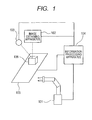
- FIG. 1 is a diagram illustrating an example of the configuration of a conveying system.
- the conveying system includes a robot 101 serving as a conveying apparatus, an image obtaining apparatus 102, a light source 103, an information processing apparatus 104, and a transferring apparatus 105.
- the robot 101 is, e.g., a manipulator, a robot hand or the like.
- the robot 101 performs the action determined by the information processing apparatus 104 to manipulate an object 106 set on the transferring apparatus 105.
- the action is the operation of the robot 101 for manipulating the object 106.
- the action includes the operation of the robot 101 for grasping and conveying the object 106 to a different location.
- the image obtaining apparatus 102 is, e.g., a camera, a photosensor, a photodiode or the like.
- the image obtaining apparatus 102 obtains image information of the object 106 so as to measure the 3D shape and the state of the object 106.
- the image obtaining apparatus 102 outputs the obtained image information to the information processing apparatus 104.
- the light source 103 is, e.g., a projector.
- the light source 103 illuminates the object 106 with uniform illumination or pattern light by projecting visible light or infrared light using a laser.
- a laser range finder consisting of the image obtaining apparatus 102 and the light source 103 may be used.
- the object may be measured passively by the two image obtaining apparatuses 102 without using the light source 103.
- the 3D shape and the state of the object 106 can be measured by only one image obtaining apparatus 102, the light source 103 is unnecessary.
- the information processing apparatus 104 which functions as a conveying controlling apparatus, is constituted by, e.g., a calculator such as a computer and an auxiliary storage device such as a hard disk drive.
- the information processing apparatus 104 which is connected to the robot 101, the image obtaining apparatus 102, the light source 103 and the transferring apparatus 105 via interface devices, performs communication with each device and thus controls the action thereof.
- the information processing apparatus 104 stores therein information of the 3D shape and the state of the object 106, the working procedure of the robot 101 and the like.
- the information processing apparatus 104 decides the 3D shape and the state of the object 106 and determines the conveying method by referring to the information stored in the information processing apparatus 104, based on the image information input from the image obtaining apparatus 102. Besides, the information processing apparatus 104 plans the action of the robot 101 by referring to the information stored in the information processing apparatus 104, and outputs the obtained plan to the robot 101.
- the transferring apparatus 105 is, e.g., a belt conveyer.
- the transferring apparatus 105 of which the operation is controlled by the information processing apparatus 104, transfers the object 106 to the image obtainable range of the image obtaining apparatus 102.
- the object 106 which is manipulated by the robot 101, is the object to which a recycling process is performed.
- the object 106 is, e.g., a toner cartridge in which a toner has been contained.
- the hollow body which can be filled with powder or liquid is assumed as the object.
- FIG. 2 is a block diagram illustrating a functional constitution of the information processing apparatus.
- the functional constitution illustrated in FIG. 2 is achieved on the premise that a CPU (central processing unit) of the information processing apparatus 104 reads the program stored in, e.g., an ROM (read only memory) and expands the read program to a memory.
- a CPU central processing unit
- ROM read only memory
- the information processing apparatus 104 includes an image obtaining unit 201, a 3D shape measuring unit 202, a part DB (database) 203, a state measuring unit 204, a state DB 205, a conveying method determining unit 206, an action planning unit 207, and an operation DB 208.
- the image obtaining unit 201 is constituted by, e.g., a capture board and an RAM (random-access memory).
- the image obtaining unit 201 obtains the image information from the image obtaining apparatus 102, and outputs the obtained image information to the 3D shape measuring unit 202 and the state measuring unit 204.
- the 3D shape measuring unit 202 which is an example of a shape measuring unit, recognizes the 3D shape of the object 106 based on the obtained image information. More specifically, the 3D shape measuring unit 202 determines the 3D shape of the object 106 by referring to the information of part type and shape stored in the part DB 203, and outputs the determined shape to the conveying method determining unit 206.
- the part DB 203 stores therein the information of part type and shape of the object 106 to which the recycling process is performed.
- the 3D shape measuring unit 202 appropriately refers to the information in the part DB 203.
- the data is the model data such as CAD (computer-aided design) data, CG (computer graphics) polygon data and the like.
- the state measuring unit 204 which is an example of a state measuring unit, recognizes the state of the object 106 based on the obtained image information. More specifically, the state measuring unit 204 determines the state of the object 106 by referring to the parameter information stored in the state DB 205, and outputs the determined state to the conveying method determining unit 206.
- the state DB 205 stores therein the parameter information of the object 106 to which the recycling process is performed, and the parameter information of the periphery of the object 106.
- the parameter information includes, e.g., a table showing the correspondence relation between the amount and the state of the content of the object 106, a table showing the correspondence relation between the degree of adhesion of the content to the outside of the object 106 and the state as to whether or not the content has been actually adhered outside the container, and a table showing the correspondence relation between the diffusion amount and the state of the content on the periphery of the object 106.
- the state measuring unit 204 appropriately refers to the information in the state DB 205.
- the conveying method determining unit 206 which is an example of a conveying method determining unit, determines the conveying method of the object 106 based on the 3D shape information input from the 3D shape measuring unit 202 and the state information input from the state measuring unit 204.
- the conveying method determining unit 206 outputs the process type as the determined conveying method to the action planning unit 207.
- the action planning unit 207 which is an example of a controlling unit, plans the action of the robot 101 based on process type input from the conveying method determining unit 206. More specifically, the action planning unit 207 plans the action of the object 106 by referring to the information of part type and work procedure stored in the operation DB 208. Then, the action planning unit 207 outputs the planned action plan as an operation instruction to the robot 101, and the robot 101 operations according to the operation instruction input from the action planning unit 207. Incidentally, the action planning unit 207 also controls the operations of the image obtaining apparatus 102, the light source 103 and the transferring apparatus 105 respectively connected to the information processing apparatus 104.
- the operation DB 208 stores therein the information of part type and work procedure to be referred when the action planning unit 207 plans the action. That is, the action planning unit 207 appropriately refers to the information in the operation DB 208.
- FIG. 3 is a flow chart indicating the process of the conveying system according to the present embodiment.
- each apparatus or device of the conveying system performs initialization in response to activation of the conveying system by an operator.
- the CPU reads and expands the programs to the memory to enable various processes.
- the robot 101 and the image reading apparatus 102 perform device parameter reading, return to the initial location, and the like to enable usable states.
- the action planning unit 207 drives the transferring apparatus 105 to arrange and locate the object 106 within the image obtainable range of the image obtaining apparatus 102.
- the image obtaining unit 201 obtains the information related to the object 106, i.e., the image information, from the image obtaining apparatus 102.
- the 3D shape measuring unit 202 performs the 3D shape measurement.
- the process in S303 will be described with reference to a flow chart illustrated in FIG. 4 .
- FIG. 4 is the flow chart indicating the process to be performed in S303.
- the 3D shape measuring unit 202 performs pattern matching of the object 106. More specifically, the 3D shape measuring unit 202 decides the part type of the object 106 by referring to the information in the part DB 203, based on the image information of the object 106. In a typical pattern matching method, for example, the pattern of the object 106 and the input image are compared with each other by correlation-based matching to estimate the most-similar location and position, and the part type of the object 106 is determined based on the estimated location and position. Incidentally, another pattern matching process by which the part type of the object 106 can be decided may be used.
- the 3D shape measuring unit 202 performs model fitting of the object 106 based on the decided result. For example, the location and the position of the object 106 are measured by projecting, with use of uniform illumination, the object 106 onto a 2D (two-dimensional) image based on the edge of the object and the CAD data of the part DB 203. Alternatively, a range image on the surface is obtained by the IPC algorithm based on the location information of the measurement line by using the RC method or the DL method using pattern light, and thus the location and the position of the object 106 are measured.
- the 3D shape measuring unit 202 performs a deficiency/lack deciding process of the object 106 based on the measured result. More specifically, the 3D shape measuring unit 202 partially performs matching-degree evaluation in the model fitting in S402, and, if there is no matching apparently, decides that there is a deficiency or lack at the relevant portion. This process corresponds to an example of the process to be performed by a deciding unit.
- the lack implies a case where the object 106 lacks a part or parts.
- S304 the state measuring unit 204 performs state measurement.
- the process in S304 will be described with reference to a flow chart illustrated in FIG. 5 .
- FIG. 5 is the flow chart indicating the process to be performed in S304.
- the state measuring unit 204 decides whether or not there is a diffusion of the content of the object 106 outside the container. More specifically, based on the image information of the periphery of the object 106, the state measuring unit 204 decides whether or not there is the diffusion of the content outside the container, by referring to the table showing the correspondence relation between the diffusion amount and the state of the content of the periphery of the object 106 stored in the state DB 205. If it is decided that there is the diffusion of the content outside the container, the process is advanced to S502 in which the action planning unit 207 temporarily stops the operation of the conveying system. Therefore, it is possible to prevent that the contents are excessively diffused outside the container. On the other hand, if it is decided that there is no diffusion of the content outside the container, the process is advanced to S503.
- the state measuring unit 204 decides the outward appearance of the object 106. More specifically, based on the image information of the object 106, the state measuring unit 204 decides whether or not the content of the container has been adhered to the outside of the container and further decides the portion where the content has been adhered, by referring to the table, stored in the state DB 205, showing the correspondence relation between the degree of adhesion of the content to the outside of the object 106 and the state as to whether or not the content has been adhered.
- the state measuring unit 204 decides the state of the content of the object 106. More specifically, based on the image information of the object 106, the state measuring unit 204 decides the amount of the content by referring to the table showing the correspondence relation between the amount and the state of the content of the object 106 stored in the state DB 205. This process corresponds to an example of the process to be performed by a content deciding unit.
- the conveying method determining unit 206 determines the conveying method of the object 106 based on the results measured in S303 and S304. For example, it is assumed that it is decided in the deficiency/lack deciding process of S403 that there is a hole in the object 106 and it is decided in the object content deciding process of S504 that there is the content in the object. In this case, the conveying method determining unit 206 determines the conveying method of grasping and conveying the object 106 while covering the hole so as to not diffuse the content of the object 106, and outputs the determined conveying method to the action planning unit 207.
- the action planning unit 207 determines the action plan of the robot 101 to achieve the determined conveying method.
- the action planning unit 207 outputs the determined action plan to the robot 101. Therefore, the robot 101 performs the operation based on the action plan.
- the image obtaining unit 201 decides whether or not the next object 106 exists on the transferring apparatus 105, based on the input image from the image obtaining apparatus 102. If it is decided that the next object 106 exists, the process is returned to S302 in which the information processing apparatus 104 repeats the above processes. On the other hand, if it is decided that the next object 106 does not exist, the process is ended.
- the 3D shape of the object 106 and the state of the content of the object 106 are measured, and the conveying method by the robot 101 is determined based on the measured results. For example, if it is decided that there is the hole in the object 106 and it is further decided that the content has been contained in the object 106, the action plan for achieving the conveying method of grasping and conveying the object 106 so as to cover the portion of the hole is output to the robot 101. Therefore, since the robot 101 grasps the object 106 according to the action plan, it is possible to convey the object so as to prevent the content from being diffused.
- the hand of the robot 101 may directly cover the hole, or the portion different from the hand of the robot 101 may cover the hole.
- the 3D shape and the state of the object 106 are measured, for example, it is possible to cope with a case where a physical object for which the recycling process is not actually assumed is conveyed. In other words, it is possible to stop the conveying system when the unassumed physical object is conveyed.
- the action plan is determined to achieve the conveying method of the object in which the hole is covered.
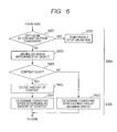
- FIG. 6 is a flow chart indicating the process of the conveying system according to the present embodiment.
- the process indicated by the flow chart in FIG. 6 corresponds to the state measuring process of S304 and the conveying method determining process of S305 respectively indicated in FIG. 3 .
- the flow chart of FIG. 6 only the processes in S601 to S604 different from the process in the first embodiment will be described. Namely, the processes same as those in the first embodiment are indicated by the respective same step numbers, and the descriptions thereof will be omitted.
- the state measuring unit 204 decides whether or not the content has been contained in the object 106. That is, based on the image information of the object 106, the state measuring unit 204 decides whether or not the content has been contained in the object 106, by referring to the table showing the correspondence relation between the amount and the state of the content of the object 106 stored in the state DB 205. Then, if it is decided that the content is not contained in the object, the object content deciding process is ended, and the process is advanced to S603. On the other hand, if it is decided that the content has been contained in the object, the process is advanced to S602.
- the state measuring unit 204 decides the amount of the content of the object 106. In this step, it is decided what extent the amount of the content is, in comparison with the state that the amount of the content is zero.
- This process corresponds to an example of the process to be performed by an amount deciding unit. More specifically, based on the image information of the object 106, the state measuring unit 204 decides and confirms what extent the amount of the content contained in the object 106 is, by referring to the table showing the correspondence relation between the amount and the state of the content of the object 106 stored in the state DB 205. After the decision, the object content deciding process is ended, and the process is advanced to S604.
- the conveying method determining unit 206 determines the conveying speed of the robot 101.
- the maximum speed at which the robot 101 conveys the object is determined by the conveying method determining unit 206 as the conveying speed. Then, the process is advanced to S306.
- the conveying method determining unit 206 determines the conveying speed of the robot 101 according to the decided amount of the content of the object 106. That is, the conveying speed is determined so as to operate the robot 101 at high conveying speed when the amount of the content is small, whereas the conveying speed is determined so as to operate the robot at low conveying speed when the amount of the content is large. Then, the process is advanced to S306. According to the present embodiment, the amount of the content of the object 106 is first decided. Then, as the decided amount of the content is smaller, the higher conveying speed is determined. In contrast, as the decided amount of the content is larger, the lower conveying speed is determined. Therefore, the conveying system will convey the object 106 as fast as possible while preventing the content of the object 106 from being diffused.
- the conveyance of the object is controlled in the case where the content exists within the container.
- a case where the content exists outside the container will be described. That is, in the present embodiment, in a case where the content has been adhered outside the object 106 (i.e., to the outside surface of the container), the object 106 is conveyed so as to prevent the adhered content from being diffused.
- FIG. 7 is a flow chart indicating the process of the conveying system according to the present embodiment.
- the process indicated by the flow chart in FIG. 7 corresponds to the state measuring process of S304 indicated in FIG. 3 .
- the flow chart of FIG. 7 only an object outward appearance deciding process in S701 to S703 different from the process in the first embodiment will be described. Namely, the processes same as those in the first embodiment are indicated by the respective same step numbers, and the descriptions thereof will be omitted.
- the state measuring unit 204 decides whether or not the content has been adhered outside the object 106 (i.e., to the outside surface of the container). This process corresponds to an example of the process to be performed by an adhesion deciding unit. Based on the image information of the object 106, the state measuring unit 204 decides and confirms whether or not the content has been adhered outside the object 106 (container), by referring to the table, stored in the state DB 205, showing the correspondence relation between the degree of adhesion of the content of the object 106 to the outside of the container and the state as to whether or not the content has been adhered. Then, if it is decided that the content is not adhered, the object outward appearance deciding process is ended, and the process is advanced to S504. On the other hand, if it is decided that the content has been adhered, the process is advanced to S702.
- the state measuring unit 204 decides to which portion of the outside surface of the object 106 the content thereof has been adhered. More specifically, the state measuring unit 204 decides the adhesion portion by comparing the state that the content of the object 106 is not adhered outside the container with the state that the content has been adhered outside the container.
- the conveying method determining unit 206 determines the grasping method. That is, the conveying method determining unit determines how the robot 101 grasps the object 106. For example, if it causes the robot 101 to grasp the object 106 so as to cover the adhesion portion of the content, it is possible to prevent that the content of the object 106 adhered outside the container is diffused.
- the object outward appearance deciding process is ended, and the process is advanced to S504.
- the present embodiment when the content of the object 106 has been adhered outside the container, it is possible, by grasping the object 106 so as to cover the adhesion portion of the content, to convey the object 106 while preventing the diffusion of the content adhered outside the container as much as possible.
- the above first to third embodiments pay attention to the shape of the object 106, the amount of the content thereof, and the adhesion portion of the outside surface of the container to which the content has been adhered.
- the present embodiment pays attention to the position (attitude) of the object 106. Namely, in the present embodiment, it is possible to prevent a diffusion of the content, by causing the robot 101 to change the position of the object 106. That is, even if there is a possibility that the content is spilled by the position of the object 106, it is possible to prevent the content from being diffused, by conveying the object after changing the position thereof to the position by which the content is not spilled.
- FIG. 8 is a flow chart indicating the process of the conveying system according to the present embodiment.
- the process indicated by the flow chart in FIG. 8 corresponds to the state measuring process of S304 and the conveying method determining process of S305 respectively indicated in FIG. 3 .
- the flow chart of FIG. 8 only the processes in S801 to S805 different from the process in the first embodiment will be described. Namely, the processes same as those in the first embodiment are indicated by the respective same step numbers, and the descriptions thereof will be omitted.
- the state measuring unit 204 decides whether or not the content exists in the object 106. That is, based on the image information of the object 106, the state measuring unit 204 decides whether or not the content has been contained in the object 106, by referring to the table, stored in the state DB 205, showing the correspondence relation between the amount and the state of the content in the object 106. If it is decided that the content is not contained, the object content deciding process is ended, and the process is advanced to S804. On the other hand, if it is decided that the content has been contained, the process is advanced to S802.
- the state measuring unit 204 decides whether or not the object 106 is in the position by which the content is spilled. In this step, based on the result of the deficiency/lack detecting process in S403, the state measuring unit decides the position by referring to the information indicating whether or not there is the hole in the object 106. Then, if it is decided that the object 106 is not in the position by which the content is spilled, the process is advanced to S805. On the other hand, if it is decided that the object 106 is in the position by which the content is spilled, the process is advanced to S803.
- the action planning unit 207 changes the position of the object 106. That is, based on the decided result in S802, the action planning unit 207 changes the position of the object 106 to the position by which the content is not spilled. For example, if the object 106 is a toner cartridge in which a toner has been contained and there is a hole on the side of the toner cartridge, the position thereof is changed by turning the hole up so as to not spill the toner from the toner cartridge.
- the conveying method determining unit 206 determines the conveying position (conveying attitude) of the object 106. That is, the conveying method determining unit 206 determines the conveying method so as to convey the object 106 in an arbitrary conveying position. If the object 106 is assumed as the toner cartridge, it is decided here that a toner is not contained in the toner cartridge. Therefore, even if there is a hole in the toner cartridge, it is possible to determine the conveying position of the toner cartridge so as to convey the toner cartridge irrespective of whether the hole turns up or down. After then, the conveying method determining process is ended, and the process is advanced to S306.
- the conveying method determining unit 206 determines the conveying position of the object 106 so as to maintain the position of the object 106 by which the content is not spilled. For example, if the object 106 is the toner cartridge in which the toner has been contained, the conveying method is determined so as to maintain the conveying position by which the hole in the toner cartridge up is turned up. After then, the conveying method determining process is ended, and the process is advanced to S306.
- the object 106 it is first decided whether or not the object 106 is in the position by which the content is spilled out of the container. Then, if it is decided that the object is in the position by which the content is spilled, the position of the object 106 is changed to that by which the content is not spilled. Then, the object is conveyed in the changed conveying position by which the content is not spilled. Thus, it is possible to convey the object so as to prevent the content from being diffused.
- the object 106 is conveyed so as to prevent the diffusion of the content.
- a method of stopping the conveying system itself will be described. That is, in a case where the contents of the object 106 are excessively diffused outside the container, the conveying system is temporarily stopped, and the situation of the time with which the robot 101 cannot cope is notified to an operator.
- FIG. 9 is a diagram illustrating an example of the configuration of a conveying system according to the present embodiment.
- a wide-range image obtaining apparatus 107 is added to the configuration illustrated in FIG. 1 .
- the state measuring unit 204 decides in S501 whether or not there is the diffusion of the content of the object 106 outside the container. In this step, based on the image information obtained in S301, the state measuring unit 204 decides whether or not the content of the object 106 has been diffused outside the container to the extent equal to or higher than the preset state.
- the image information to be used here in addition to the image information obtained by the image obtaining apparatus 102, the image information obtained by the wide-range image obtaining apparatus 107 is used if the target range is wide.
- the state measuring unit 204 decides whether or not there is the diffusion of the content outside the container, by referring to the table showing the correspondence relation between the diffusion amount and the state of the content on the periphery of the object 106 stored in the state DB 205.
- This process corresponds to an example of the process to be performed by a diffusion deciding unit.
- the process is advanced to S502 in which the action planning unit 207 temporarily stops the operation of the conveying system.
- the conveying system if the content of the object 106 has been diffused outside the container to the extent equal to or higher than the set state, the conveying system is temporarily stopped. Therefore, if the content of the object 106 is powder such as a toner, it is possible to prevent that the content is excessively diffused.
- the case that also the image information obtained by the wide-range image obtaining apparatus 107 is used has been described. However, if the image obtaining apparatus 102 can obtain the image information indicating that the content has been diffused on the periphery of the object 106, the wide-range image obtaining apparatus 107 can be omitted.
- the content to be treated in the present invention may include any physical object, matter or substance if it can be contained in the object 106.
- the toner described in the first embodiment is used.
- the content is not limited to the powder such as the toner, but may be liquid.
- the state of the content of the object 106 in the present invention may include any state if the amount thereof can be measured.
- the state corresponds to the amount of the toner contained in the toner cartridge.
- the state is not limited to the amount of the powder such as the toner, but may be an amount of liquid.
- the content adhered outside the container in the present invention may include any content if it can be contained in the object 106.
- the toner contained in the toner cartridge is used.
- the content adhered outside the container is not limited to the powder such as the toner, but may be liquid.
- the hole in the present invention may include any hole if it occurs in the object 106.
- the hole occurring due to the deficiency or lack as in the fourth embodiment is used as the hole.
- the hole in the object 106 may be either the hole occurring due to the deficiency or the hole occurring due to the lack.
- the state in the present invention may include any state if it is related to the diffusion state of the content of the object 106.
- the diffusion state of the toner as in the fifth embodiment is used as the state.
- the diffused content is not limited to the powder such as the toner, but may be liquid.
- the present invention can be achieved also by the following process.
- it is possible to achieve the present invention by supplying the programs for realizing the functions of the above embodiments to the conveying system or the information processing apparatus 104 via networks or various storage media and causing the computer (or the CPU, etc.) of the information processing apparatus 104 to read and execute the supplied programs.
- Embodiment(s) of the present invention can also be realized by a computer of a system or apparatus that reads out and executes computer executable instructions (e.g., one or more programs) recorded on a storage medium (which may also be referred to more fully as a 'non-transitory computer-readable storage medium') to perform the functions of one or more of the above-described embodiment(s) and/or that includes one or more circuits (e.g., application specific integrated circuit (ASIC)) for performing the functions of one or more of the above-described embodiment(s), and by a method performed by the computer of the system or apparatus by, for example, reading out and executing the computer executable instructions from the storage medium to perform the functions of one or more of the above-described embodiment(s) and/or controlling the one or more circuits to perform the functions of one or more of the above-described embodiment(s).
- computer executable instructions e.g., one or more programs
- a storage medium which may also be referred to more fully as
- the computer may comprise one or more processors (e.g., central processing unit (CPU), micro processing unit (MPU)) and may include a network of separate computers or separate processors to read out and execute the computer executable instructions.
- the computer executable instructions may be provided to the computer, for example, from a network or the storage medium.
- the storage medium may include, for example, one or more of a hard disk, a random-access memory (RAM), a read only memory (ROM), a storage of distributed computing systems, an optical disk (such as a compact disc (CD), digital versatile disc (DVD), or Blu-ray Disc (BD)TM), a flash memory device, a memory card, and the like.
Landscapes
- Engineering & Computer Science (AREA)
- Physics & Mathematics (AREA)
- General Physics & Mathematics (AREA)
- Automation & Control Theory (AREA)
- Quality & Reliability (AREA)
- Manufacturing & Machinery (AREA)
- General Engineering & Computer Science (AREA)
- Robotics (AREA)
- Mechanical Engineering (AREA)
- Manipulator (AREA)
- Specific Conveyance Elements (AREA)
- Control Of Conveyors (AREA)
- Length Measuring Devices By Optical Means (AREA)
Abstract
Description
- The present invention relates to conveying controlling apparatus and method which control a conveying apparatus conveying an object, a program which is used to achieve the conveying controlling method, and a conveying system to which the conveying controlling apparatus and method are applicable. Incidentally, in the present application, it is assumed that "object", "object container" and "container" which appear in what follows are equivalent.
- When a conveying apparatus which conveys an object is used in a recycling process, how to convey the object by the conveying apparatus is generally determined by recognizing the shape of the object and checking the recognized shape and a database with each other. Here, Japanese Patent Application Laid-Open No.
2000-241141 - Besides, Japanese Patent Application Laid-Open No.
2001-022423 - For example, in a case where a container containing contents is the object to be processed in the recycling process, even if the same-shape objects are conveyed in an object conveying operation, it is necessary to change the conveying method according to the state of the object such as a state that the contents have been adhered outside a container, a state that the amount of the contents is small, or the like. For example, in a toner cartridge recycling process, when a toner cartridge containing a toner as its content is conveyed, it is necessary to actually convey the toner cartridge such that the contained toner is not diffused.
- However, it is difficult to automatically change the conveying method according to the state of the object. Therefore, under the circumstances, an operator has to convey the objects while visually confirming the objects themselves.
- Incidentally, in regard to the recycling processing apparatus disclosed in Japanese Patent Application Laid-Open No.
2000-241141 2001-022423 - The present invention, which has been completed in consideration of such conventional problems as above, is characterized by a conveying controlling apparatus which controls a conveying apparatus conveying an object container and comprises: a shape measuring unit configured to measure a 3D shape of the object container; a state measuring unit configured to measure a state of a content of the object container; a determining unit configured to determine a conveying method for the object container by the conveying apparatus based on the 3D shape measured by the shape measuring unit and the state measured by the state measuring unit; and a controlling unit configured to control an action of the conveying apparatus based on the conveying method determined by the determining unit.
- According to the present invention, it is possible to convey the object container so as to prevent the contents thereof from being diffused.
- Further features of the present invention will become apparent from the following description of exemplary embodiments with reference to the attached drawings.
-
-
FIG. 1 is a diagram illustrating an example of the configuration of a conveying system according to the first embodiment. -
FIG. 2 is a block diagram illustrating a functional constitution of an information processing apparatus according to the first embodiment. -
FIG. 3 is a flow chart indicating a process of the conveying system according to the first embodiment. -
FIG. 4 is a flow chart indicating the process of the conveying system according to the first embodiment. -
FIG. 5 is a flow chart indicating the process of the conveying system according to the first embodiment. -
FIG. 6 is a flow chart indicating a process of the conveying system according to the second embodiment. -
FIG. 7 is a flow chart indicating a process of the conveying system according to the third embodiment. -
FIG. 8 is a flow chart indicating a process of the conveying system according to the fourth embodiment. -
FIG. 9 is a diagram illustrating an example of the configuration of a conveying system according to the fifth embodiment. - Hereinafter, preferred embodiments of the present invention will be described in detail with reference to the attached drawings. Here, it should be noted that the following embodiments of the present invention do not limit the scope of application of the present invention.
- In the present embodiment, the 3D shape of an object and the state of the content (or the contents) of the object are first measured, then the part (or the parts), the location, the position (or the attitude) and the content of the object are decided based on the measured results, and the method of conveying the object is finally determined based on the decided results.
- Here, the object is a hollow body which can contain therein the content. For example, a container such as a toner cartridge is treated as the object in the embodiments. The content is the matter to be contained in the object. For example, a toner to be contained in the toner cartridge is treated as the content in the embodiments. However, the content in the embodiments includes both the content contained in the object and the content existing outside the object.
-
FIG. 1 is a diagram illustrating an example of the configuration of a conveying system. - The conveying system includes a
robot 101 serving as a conveying apparatus, animage obtaining apparatus 102, alight source 103, aninformation processing apparatus 104, and a transferringapparatus 105. - The
robot 101 is, e.g., a manipulator, a robot hand or the like. Therobot 101 performs the action determined by theinformation processing apparatus 104 to manipulate anobject 106 set on the transferringapparatus 105. Here, the action is the operation of therobot 101 for manipulating theobject 106. For example, the action includes the operation of therobot 101 for grasping and conveying theobject 106 to a different location. - The
image obtaining apparatus 102 is, e.g., a camera, a photosensor, a photodiode or the like. Theimage obtaining apparatus 102 obtains image information of theobject 106 so as to measure the 3D shape and the state of theobject 106. Theimage obtaining apparatus 102 outputs the obtained image information to theinformation processing apparatus 104. - The
light source 103 is, e.g., a projector. Thelight source 103 illuminates theobject 106 with uniform illumination or pattern light by projecting visible light or infrared light using a laser. Incidentally, a laser range finder consisting of theimage obtaining apparatus 102 and thelight source 103 may be used. Besides, the object may be measured passively by the twoimage obtaining apparatuses 102 without using thelight source 103. Besides, the 3D shape and the state of theobject 106 can be measured by only oneimage obtaining apparatus 102, thelight source 103 is unnecessary. - The
information processing apparatus 104, which functions as a conveying controlling apparatus, is constituted by, e.g., a calculator such as a computer and an auxiliary storage device such as a hard disk drive. Theinformation processing apparatus 104, which is connected to therobot 101, theimage obtaining apparatus 102, thelight source 103 and the transferringapparatus 105 via interface devices, performs communication with each device and thus controls the action thereof. Besides, theinformation processing apparatus 104 stores therein information of the 3D shape and the state of theobject 106, the working procedure of therobot 101 and the like. - In the present embodiment, the
information processing apparatus 104 decides the 3D shape and the state of theobject 106 and determines the conveying method by referring to the information stored in theinformation processing apparatus 104, based on the image information input from theimage obtaining apparatus 102. Besides, theinformation processing apparatus 104 plans the action of therobot 101 by referring to the information stored in theinformation processing apparatus 104, and outputs the obtained plan to therobot 101. - The transferring
apparatus 105 is, e.g., a belt conveyer. The transferringapparatus 105, of which the operation is controlled by theinformation processing apparatus 104, transfers theobject 106 to the image obtainable range of theimage obtaining apparatus 102. - The
object 106, which is manipulated by therobot 101, is the object to which a recycling process is performed. Theobject 106 is, e.g., a toner cartridge in which a toner has been contained. In the present embodiment, the hollow body which can be filled with powder or liquid is assumed as the object. -
FIG. 2 is a block diagram illustrating a functional constitution of the information processing apparatus. Here, it should be noted that the functional constitution illustrated inFIG. 2 is achieved on the premise that a CPU (central processing unit) of theinformation processing apparatus 104 reads the program stored in, e.g., an ROM (read only memory) and expands the read program to a memory. - The
information processing apparatus 104 includes animage obtaining unit 201, a 3Dshape measuring unit 202, a part DB (database) 203, a state measuringunit 204, astate DB 205, a conveyingmethod determining unit 206, anaction planning unit 207, and anoperation DB 208. - The
image obtaining unit 201 is constituted by, e.g., a capture board and an RAM (random-access memory). Theimage obtaining unit 201 obtains the image information from theimage obtaining apparatus 102, and outputs the obtained image information to the 3Dshape measuring unit 202 and thestate measuring unit 204. - The 3D
shape measuring unit 202, which is an example of a shape measuring unit, recognizes the 3D shape of theobject 106 based on the obtained image information. More specifically, the 3Dshape measuring unit 202 determines the 3D shape of theobject 106 by referring to the information of part type and shape stored in thepart DB 203, and outputs the determined shape to the conveyingmethod determining unit 206. - The
part DB 203 stores therein the information of part type and shape of theobject 106 to which the recycling process is performed. The 3Dshape measuring unit 202 appropriately refers to the information in thepart DB 203. Here, the data is the model data such as CAD (computer-aided design) data, CG (computer graphics) polygon data and the like. - The
state measuring unit 204, which is an example of a state measuring unit, recognizes the state of theobject 106 based on the obtained image information. More specifically, thestate measuring unit 204 determines the state of theobject 106 by referring to the parameter information stored in thestate DB 205, and outputs the determined state to the conveyingmethod determining unit 206. - The
state DB 205 stores therein the parameter information of theobject 106 to which the recycling process is performed, and the parameter information of the periphery of theobject 106. The parameter information includes, e.g., a table showing the correspondence relation between the amount and the state of the content of theobject 106, a table showing the correspondence relation between the degree of adhesion of the content to the outside of theobject 106 and the state as to whether or not the content has been actually adhered outside the container, and a table showing the correspondence relation between the diffusion amount and the state of the content on the periphery of theobject 106. Thestate measuring unit 204 appropriately refers to the information in thestate DB 205. - The conveying
method determining unit 206, which is an example of a conveying method determining unit, determines the conveying method of theobject 106 based on the 3D shape information input from the 3Dshape measuring unit 202 and the state information input from thestate measuring unit 204. The conveyingmethod determining unit 206 outputs the process type as the determined conveying method to theaction planning unit 207. - The
action planning unit 207, which is an example of a controlling unit, plans the action of therobot 101 based on process type input from the conveyingmethod determining unit 206. More specifically, theaction planning unit 207 plans the action of theobject 106 by referring to the information of part type and work procedure stored in theoperation DB 208. Then, theaction planning unit 207 outputs the planned action plan as an operation instruction to therobot 101, and therobot 101 operations according to the operation instruction input from theaction planning unit 207. Incidentally, theaction planning unit 207 also controls the operations of theimage obtaining apparatus 102, thelight source 103 and the transferringapparatus 105 respectively connected to theinformation processing apparatus 104. - The
operation DB 208 stores therein the information of part type and work procedure to be referred when theaction planning unit 207 plans the action. That is, theaction planning unit 207 appropriately refers to the information in theoperation DB 208. -
FIG. 3 is a flow chart indicating the process of the conveying system according to the present embodiment. - In S301, each apparatus or device of the conveying system performs initialization in response to activation of the conveying system by an operator. In the
information processing apparatus 104, the CPU reads and expands the programs to the memory to enable various processes. Also, therobot 101 and theimage reading apparatus 102 perform device parameter reading, return to the initial location, and the like to enable usable states. - In S302, the
action planning unit 207 drives the transferringapparatus 105 to arrange and locate theobject 106 within the image obtainable range of theimage obtaining apparatus 102. Theimage obtaining unit 201 obtains the information related to theobject 106, i.e., the image information, from theimage obtaining apparatus 102. - In S303, the 3D
shape measuring unit 202 performs the 3D shape measurement. Hereinafter, the process in S303 will be described with reference to a flow chart illustrated inFIG. 4 . - That is,
FIG. 4 is the flow chart indicating the process to be performed in S303. - In S401, the 3D
shape measuring unit 202 performs pattern matching of theobject 106. More specifically, the 3Dshape measuring unit 202 decides the part type of theobject 106 by referring to the information in thepart DB 203, based on the image information of theobject 106. In a typical pattern matching method, for example, the pattern of theobject 106 and the input image are compared with each other by correlation-based matching to estimate the most-similar location and position, and the part type of theobject 106 is determined based on the estimated location and position. Incidentally, another pattern matching process by which the part type of theobject 106 can be decided may be used. - In S402, the 3D
shape measuring unit 202 performs model fitting of theobject 106 based on the decided result. For example, the location and the position of theobject 106 are measured by projecting, with use of uniform illumination, theobject 106 onto a 2D (two-dimensional) image based on the edge of the object and the CAD data of thepart DB 203. Alternatively, a range image on the surface is obtained by the IPC algorithm based on the location information of the measurement line by using the RC method or the DL method using pattern light, and thus the location and the position of theobject 106 are measured. - In S403, the 3D
shape measuring unit 202 performs a deficiency/lack deciding process of theobject 106 based on the measured result. More specifically, the 3Dshape measuring unit 202 partially performs matching-degree evaluation in the model fitting in S402, and, if there is no matching apparently, decides that there is a deficiency or lack at the relevant portion. This process corresponds to an example of the process to be performed by a deciding unit. Here, the lack implies a case where theobject 106 lacks a part or parts. - After the process in S403, the process is advanced to S304 in
FIG. 3 . - In S304, the
state measuring unit 204 performs state measurement. Hereinafter, the process in S304 will be described with reference to a flow chart illustrated inFIG. 5 . - That is,
FIG. 5 is the flow chart indicating the process to be performed in S304. - In S501, the
state measuring unit 204 decides whether or not there is a diffusion of the content of theobject 106 outside the container. More specifically, based on the image information of the periphery of theobject 106, thestate measuring unit 204 decides whether or not there is the diffusion of the content outside the container, by referring to the table showing the correspondence relation between the diffusion amount and the state of the content of the periphery of theobject 106 stored in thestate DB 205. If it is decided that there is the diffusion of the content outside the container, the process is advanced to S502 in which theaction planning unit 207 temporarily stops the operation of the conveying system. Therefore, it is possible to prevent that the contents are excessively diffused outside the container. On the other hand, if it is decided that there is no diffusion of the content outside the container, the process is advanced to S503. - In S503, the
state measuring unit 204 decides the outward appearance of theobject 106. More specifically, based on the image information of theobject 106, thestate measuring unit 204 decides whether or not the content of the container has been adhered to the outside of the container and further decides the portion where the content has been adhered, by referring to the table, stored in thestate DB 205, showing the correspondence relation between the degree of adhesion of the content to the outside of theobject 106 and the state as to whether or not the content has been adhered. - In S504, the
state measuring unit 204 decides the state of the content of theobject 106. More specifically, based on the image information of theobject 106, thestate measuring unit 204 decides the amount of the content by referring to the table showing the correspondence relation between the amount and the state of the content of theobject 106 stored in thestate DB 205. This process corresponds to an example of the process to be performed by a content deciding unit. - After the process in S504, the process is advanced to S305 in
FIG. 3 . - In S305, the conveying
method determining unit 206 determines the conveying method of theobject 106 based on the results measured in S303 and S304. For example, it is assumed that it is decided in the deficiency/lack deciding process of S403 that there is a hole in theobject 106 and it is decided in the object content deciding process of S504 that there is the content in the object. In this case, the conveyingmethod determining unit 206 determines the conveying method of grasping and conveying theobject 106 while covering the hole so as to not diffuse the content of theobject 106, and outputs the determined conveying method to theaction planning unit 207. - In S306, the
action planning unit 207 determines the action plan of therobot 101 to achieve the determined conveying method. - In S307, the
action planning unit 207 outputs the determined action plan to therobot 101. Therefore, therobot 101 performs the operation based on the action plan. - In S308, the
image obtaining unit 201 decides whether or not thenext object 106 exists on the transferringapparatus 105, based on the input image from theimage obtaining apparatus 102. If it is decided that thenext object 106 exists, the process is returned to S302 in which theinformation processing apparatus 104 repeats the above processes. On the other hand, if it is decided that thenext object 106 does not exist, the process is ended. - According to the present embodiment, the 3D shape of the
object 106 and the state of the content of theobject 106 are measured, and the conveying method by therobot 101 is determined based on the measured results. For example, if it is decided that there is the hole in theobject 106 and it is further decided that the content has been contained in theobject 106, the action plan for achieving the conveying method of grasping and conveying theobject 106 so as to cover the portion of the hole is output to therobot 101. Therefore, since therobot 101 grasps theobject 106 according to the action plan, it is possible to convey the object so as to prevent the content from being diffused. Incidentally, in this case, the hand of therobot 101 may directly cover the hole, or the portion different from the hand of therobot 101 may cover the hole. - Moreover, since the 3D shape and the state of the
object 106 are measured, for example, it is possible to cope with a case where a physical object for which the recycling process is not actually assumed is conveyed. In other words, it is possible to stop the conveying system when the unassumed physical object is conveyed. - Incidentally, when it is decided that there is the hole in the
object 106, it may be possible to determine the conveying method of grasping and conveying theobject 106 so as to cover the portion of the hole, irrespective of whether or not the content has been contained in the object. - In the first embodiment, when there is the hole in the
object 106, the action plan is determined to achieve the conveying method of the object in which the hole is covered. In the present embodiment, it is possible, by changing the conveying speed of therobot 101 based on an amount of the content, to convey theobject 106 as fast as possible while preventing the content from being diffused. That is, the amount of the content of theobject 106 is first decided. Then, based on the decided amount of the content, therobot 101 is operated fast when the amount of the content is small, whereas the robot is operated slow when the amount of the content is large. -
FIG. 6 is a flow chart indicating the process of the conveying system according to the present embodiment. - The process indicated by the flow chart in
FIG. 6 corresponds to the state measuring process of S304 and the conveying method determining process of S305 respectively indicated inFIG. 3 . Hereinafter, in the flow chart ofFIG. 6 , only the processes in S601 to S604 different from the process in the first embodiment will be described. Namely, the processes same as those in the first embodiment are indicated by the respective same step numbers, and the descriptions thereof will be omitted. - In S601, the
state measuring unit 204 decides whether or not the content has been contained in theobject 106. That is, based on the image information of theobject 106, thestate measuring unit 204 decides whether or not the content has been contained in theobject 106, by referring to the table showing the correspondence relation between the amount and the state of the content of theobject 106 stored in thestate DB 205. Then, if it is decided that the content is not contained in the object, the object content deciding process is ended, and the process is advanced to S603. On the other hand, if it is decided that the content has been contained in the object, the process is advanced to S602. - In S602, the
state measuring unit 204 decides the amount of the content of theobject 106. In this step, it is decided what extent the amount of the content is, in comparison with the state that the amount of the content is zero. This process corresponds to an example of the process to be performed by an amount deciding unit. More specifically, based on the image information of theobject 106, thestate measuring unit 204 decides and confirms what extent the amount of the content contained in theobject 106 is, by referring to the table showing the correspondence relation between the amount and the state of the content of theobject 106 stored in thestate DB 205. After the decision, the object content deciding process is ended, and the process is advanced to S604. - In S603, the conveying
method determining unit 206 determines the conveying speed of therobot 101. In the present embodiment, the maximum speed at which therobot 101 conveys the object is determined by the conveyingmethod determining unit 206 as the conveying speed. Then, the process is advanced to S306. - On the other hand, in S604, the conveying
method determining unit 206 determines the conveying speed of therobot 101 according to the decided amount of the content of theobject 106. That is, the conveying speed is determined so as to operate therobot 101 at high conveying speed when the amount of the content is small, whereas the conveying speed is determined so as to operate the robot at low conveying speed when the amount of the content is large. Then, the process is advanced to S306.
According to the present embodiment, the amount of the content of theobject 106 is first decided. Then, as the decided amount of the content is smaller, the higher conveying speed is determined. In contrast, as the decided amount of the content is larger, the lower conveying speed is determined. Therefore, the conveying system will convey theobject 106 as fast as possible while preventing the content of theobject 106 from being diffused. - In the above first and second embodiments, the conveyance of the object is controlled in the case where the content exists within the container. However, in the present embodiment, a case where the content exists outside the container will be described. That is, in the present embodiment, in a case where the content has been adhered outside the object 106 (i.e., to the outside surface of the container), the
object 106 is conveyed so as to prevent the adhered content from being diffused. -
FIG. 7 is a flow chart indicating the process of the conveying system according to the present embodiment. - The process indicated by the flow chart in
FIG. 7 corresponds to the state measuring process of S304 indicated inFIG. 3 . Hereinafter, in the flow chart ofFIG. 7 , only an object outward appearance deciding process in S701 to S703 different from the process in the first embodiment will be described. Namely, the processes same as those in the first embodiment are indicated by the respective same step numbers, and the descriptions thereof will be omitted. - In S701, the
state measuring unit 204 decides whether or not the content has been adhered outside the object 106 (i.e., to the outside surface of the container). This process corresponds to an example of the process to be performed by an adhesion deciding unit. Based on the image information of theobject 106, thestate measuring unit 204 decides and confirms whether or not the content has been adhered outside the object 106 (container), by referring to the table, stored in thestate DB 205, showing the correspondence relation between the degree of adhesion of the content of theobject 106 to the outside of the container and the state as to whether or not the content has been adhered. Then, if it is decided that the content is not adhered, the object outward appearance deciding process is ended, and the process is advanced to S504. On the other hand, if it is decided that the content has been adhered, the process is advanced to S702. - In S702, the
state measuring unit 204 decides to which portion of the outside surface of theobject 106 the content thereof has been adhered. More specifically, thestate measuring unit 204 decides the adhesion portion by comparing the state that the content of theobject 106 is not adhered outside the container with the state that the content has been adhered outside the container. - In S703, the conveying
method determining unit 206 determines the grasping method. That is, the conveying method determining unit determines how therobot 101 grasps theobject 106. For example, if it causes therobot 101 to grasp theobject 106 so as to cover the adhesion portion of the content, it is possible to prevent that the content of theobject 106 adhered outside the container is diffused. After the grasping method was determined, the object outward appearance deciding process is ended, and the process is advanced to S504. - According to the present embodiment, when the content of the
object 106 has been adhered outside the container, it is possible, by grasping theobject 106 so as to cover the adhesion portion of the content, to convey theobject 106 while preventing the diffusion of the content adhered outside the container as much as possible. - The above first to third embodiments pay attention to the shape of the
object 106, the amount of the content thereof, and the adhesion portion of the outside surface of the container to which the content has been adhered. The present embodiment pays attention to the position (attitude) of theobject 106. Namely, in the present embodiment, it is possible to prevent a diffusion of the content, by causing therobot 101 to change the position of theobject 106. That is, even if there is a possibility that the content is spilled by the position of theobject 106, it is possible to prevent the content from being diffused, by conveying the object after changing the position thereof to the position by which the content is not spilled. -
FIG. 8 is a flow chart indicating the process of the conveying system according to the present embodiment. - The process indicated by the flow chart in
FIG. 8 corresponds to the state measuring process of S304 and the conveying method determining process of S305 respectively indicated inFIG. 3 . Hereinafter, in the flow chart ofFIG. 8 , only the processes in S801 to S805 different from the process in the first embodiment will be described. Namely, the processes same as those in the first embodiment are indicated by the respective same step numbers, and the descriptions thereof will be omitted. - In S801, the
state measuring unit 204 decides whether or not the content exists in theobject 106. That is, based on the image information of theobject 106, thestate measuring unit 204 decides whether or not the content has been contained in theobject 106, by referring to the table, stored in thestate DB 205, showing the correspondence relation between the amount and the state of the content in theobject 106. If it is decided that the content is not contained, the object content deciding process is ended, and the process is advanced to S804. On the other hand, if it is decided that the content has been contained, the process is advanced to S802. - In S802, the
state measuring unit 204 decides whether or not theobject 106 is in the position by which the content is spilled. In this step, based on the result of the deficiency/lack detecting process in S403, the state measuring unit decides the position by referring to the information indicating whether or not there is the hole in theobject 106. Then, if it is decided that theobject 106 is not in the position by which the content is spilled, the process is advanced to S805. On the other hand, if it is decided that theobject 106 is in the position by which the content is spilled, the process is advanced to S803. - In S803, the
action planning unit 207 changes the position of theobject 106. That is, based on the decided result in S802, theaction planning unit 207 changes the position of theobject 106 to the position by which the content is not spilled. For example, if theobject 106 is a toner cartridge in which a toner has been contained and there is a hole on the side of the toner cartridge, the position thereof is changed by turning the hole up so as to not spill the toner from the toner cartridge. - In S804, the conveying
method determining unit 206 determines the conveying position (conveying attitude) of theobject 106. That is, the conveyingmethod determining unit 206 determines the conveying method so as to convey theobject 106 in an arbitrary conveying position. If theobject 106 is assumed as the toner cartridge, it is decided here that a toner is not contained in the toner cartridge. Therefore, even if there is a hole in the toner cartridge, it is possible to determine the conveying position of the toner cartridge so as to convey the toner cartridge irrespective of whether the hole turns up or down. After then, the conveying method determining process is ended, and the process is advanced to S306. - On the other hand, in S805, the conveying
method determining unit 206 determines the conveying position of theobject 106 so as to maintain the position of theobject 106 by which the content is not spilled. For example, if theobject 106 is the toner cartridge in which the toner has been contained, the conveying method is determined so as to maintain the conveying position by which the hole in the toner cartridge up is turned up. After then, the conveying method determining process is ended, and the process is advanced to S306. - According to the present embodiment, it is first decided whether or not the
object 106 is in the position by which the content is spilled out of the container. Then, if it is decided that the object is in the position by which the content is spilled, the position of theobject 106 is changed to that by which the content is not spilled. Then, the object is conveyed in the changed conveying position by which the content is not spilled. Thus, it is possible to convey the object so as to prevent the content from being diffused. - In the first to fourth embodiments, the
object 106 is conveyed so as to prevent the diffusion of the content. In the present embodiment, a method of stopping the conveying system itself will be described. That is, in a case where the contents of theobject 106 are excessively diffused outside the container, the conveying system is temporarily stopped, and the situation of the time with which therobot 101 cannot cope is notified to an operator. -
FIG. 9 is a diagram illustrating an example of the configuration of a conveying system according to the present embodiment. In the conveying system according to the present embodiment, a wide-rangeimage obtaining apparatus 107 is added to the configuration illustrated inFIG. 1 . - As illustrated
FIG. 5 , thestate measuring unit 204 decides in S501 whether or not there is the diffusion of the content of theobject 106 outside the container. In this step, based on the image information obtained in S301, thestate measuring unit 204 decides whether or not the content of theobject 106 has been diffused outside the container to the extent equal to or higher than the preset state. As the image information to be used here, in addition to the image information obtained by theimage obtaining apparatus 102, the image information obtained by the wide-rangeimage obtaining apparatus 107 is used if the target range is wide. More specifically, thestate measuring unit 204 decides whether or not there is the diffusion of the content outside the container, by referring to the table showing the correspondence relation between the diffusion amount and the state of the content on the periphery of theobject 106 stored in thestate DB 205. This process corresponds to an example of the process to be performed by a diffusion deciding unit. - Then, if it is decided that there is the diffusion of the content outside the container, the process is advanced to S502 in which the
action planning unit 207 temporarily stops the operation of the conveying system. - According to the present embodiment, if the content of the
object 106 has been diffused outside the container to the extent equal to or higher than the set state, the conveying system is temporarily stopped. Therefore, if the content of theobject 106 is powder such as a toner, it is possible to prevent that the content is excessively diffused. - In the present embodiment, the case that also the image information obtained by the wide-range
image obtaining apparatus 107 is used has been described. However, if theimage obtaining apparatus 102 can obtain the image information indicating that the content has been diffused on the periphery of theobject 106, the wide-rangeimage obtaining apparatus 107 can be omitted. - Incidentally, the content to be treated in the present invention may include any physical object, matter or substance if it can be contained in the
object 106. As an example of the content, the toner described in the first embodiment is used. In any case, the content is not limited to the powder such as the toner, but may be liquid. - The state of the content of the
object 106 in the present invention may include any state if the amount thereof can be measured. For example, the state corresponds to the amount of the toner contained in the toner cartridge. In any case, the state is not limited to the amount of the powder such as the toner, but may be an amount of liquid. - The content adhered outside the container in the present invention may include any content if it can be contained in the
object 106. As an example of the content, the toner contained in the toner cartridge is used. In any case, the content adhered outside the container is not limited to the powder such as the toner, but may be liquid. - The hole in the present invention may include any hole if it occurs in the
object 106. For example, the hole occurring due to the deficiency or lack as in the fourth embodiment is used as the hole. In other words, the hole in theobject 106 may be either the hole occurring due to the deficiency or the hole occurring due to the lack. - The state in the present invention may include any state if it is related to the diffusion state of the content of the
object 106. For example, the diffusion state of the toner as in the fifth embodiment is used as the state. Incidentally, the diffused content is not limited to the powder such as the toner, but may be liquid. - It should be noted that the present invention is not limited to the above embodiments, modifications are possible within the scope of the present invention, and the above embodiments may appropriately be combined.
- Moreover, the present invention can be achieved also by the following process. In other words, it is possible to achieve the present invention by supplying the programs for realizing the functions of the above embodiments to the conveying system or the
information processing apparatus 104 via networks or various storage media and causing the computer (or the CPU, etc.) of theinformation processing apparatus 104 to read and execute the supplied programs. - Embodiment(s) of the present invention can also be realized by a computer of a system or apparatus that reads out and executes computer executable instructions (e.g., one or more programs) recorded on a storage medium (which may also be referred to more fully as a 'non-transitory computer-readable storage medium') to perform the functions of one or more of the above-described embodiment(s) and/or that includes one or more circuits (e.g., application specific integrated circuit (ASIC)) for performing the functions of one or more of the above-described embodiment(s), and by a method performed by the computer of the system or apparatus by, for example, reading out and executing the computer executable instructions from the storage medium to perform the functions of one or more of the above-described embodiment(s) and/or controlling the one or more circuits to perform the functions of one or more of the above-described embodiment(s). The computer may comprise one or more processors (e.g., central processing unit (CPU), micro processing unit (MPU)) and may include a network of separate computers or separate processors to read out and execute the computer executable instructions. The computer executable instructions may be provided to the computer, for example, from a network or the storage medium. The storage medium may include, for example, one or more of a hard disk, a random-access memory (RAM), a read only memory (ROM), a storage of distributed computing systems, an optical disk (such as a compact disc (CD), digital versatile disc (DVD), or Blu-ray Disc (BD)™), a flash memory device, a memory card, and the like.
- While the present invention has been described with reference to exemplary embodiments, it is to be understood that the invention is not limited to the disclosed exemplary embodiments. The scope of the following claims is to be accorded the broadest interpretation so as to encompass all such modifications and equivalent structures and functions.
Claims (12)
- A conveying controlling apparatus for controlling a conveying apparatus for conveying an object container, comprising:a shape measuring unit configured to measure a 3D (three-dimensional) shape of the object container;a state measuring unit configured to measure a state of a content of the object container;a determining unit configured to determine a conveying method for the object container by the conveying apparatus based on the 3D shape measured by the shape measuring unit and the state measured by the state measuring unit; anda controlling unit configured to control an action of the conveying apparatus based on the conveying method determined by the determining unit.
- The conveying controlling apparatus according to Claim 1, further comprising a deciding unit configured to decide a deficiency or lack of the object container based on the 3D shape measured by the shape measuring unit, wherein
in a case where it is decided by the deciding unit that there is a hole in the object container, the determining unit determines a conveying method in which the hole is covered. - The conveying controlling apparatus according to Claim 2, further comprising a content deciding unit configured to decide whether or not the content is contained in the object container, as the state measured by the state measuring unit, wherein
in a case where it is decided by the deciding unit that there is the hole in the object container and it is decided by the content deciding unit that the content is contained in the object container, the determining unit determines the conveying method in which the hole is covered. - The conveying controlling apparatus according to Claim 1, further comprising a deciding unit configured to decide a deficiency or lack of the object container based on the 3D shape measured by the shape measuring unit, wherein
in a case where it is decided by the deciding unit that there is a hole in the object container, the determining unit determines a conveying method in which the object container is in a position by which the hole is turned up. - The conveying controlling apparatus according to Claim 1, further comprising:a deciding unit configured to decide a deficiency or lack of the object container based on the 3D shape measured by the shape measuring unit; andan amount deciding unit configured to decide an amount of the content, as the state measured by the state measuring unit, whereinin a case where it is decided by the deciding unit that there is the deficiency or lack in the object container, the determining unit determines conveying speed of conveying the object container according to the amount of the content decided by the amount deciding unit.
- The conveying controlling apparatus according to Claim 1, further comprising an adhesion deciding unit configured to decide whether or not the content has been adhered to an outer surface of the object container, as the state measured by the state measuring unit, wherein
in a case where it is decided by the adhesion deciding unit that the content has been adhered, the determining unit determines a conveying method in which a diffusion of the adhered content is prevented. - The conveying controlling apparatus according to Claim 1, further comprising a diffusion deciding unit configured to decide whether or not the content of the object container has been diffused, based on image information of a periphery of the object container, as the state measured by the state measuring unit, wherein
in a case where it is decided by the diffusion deciding unit that the content of the object container has been diffused, the controlling unit stops conveying the object container. - A conveying controlling apparatus for controlling a conveying apparatus for conveying an object container, comprising:a deciding unit configured to decide whether or not there is a hole in the object container;a determining unit configured to, in a case where it is decided by the deciding unit that there is the hole in the object container, determine a conveying method so as to cover the hole; anda controlling unit configured to control an action of the conveying apparatus based on the conveying method determined by the determining unit.
- A conveying system which comprises a conveying apparatus for conveying an object container and the conveying controlling apparatus according to any one of claims 1 to 8 for controlling the conveying apparatus,
wherein the conveying apparatus conveys the object container by the conveying method determined by the determining unit, under the control of the controlling unit. - A conveying controlling method which controls a conveying apparatus for conveying an object container, comprising:measuring a 3D shape of the object container;measuring a state of a content of the object container;determining a conveying method for the object container by the conveying apparatus based on the measured 3D shape and the measured state; andcontrolling an action of the conveying apparatus based on the determined conveying method.
- A conveying controlling method which controls a conveying apparatus for conveying an object container, comprising:deciding whether or not there is a hole in the object container;determining, in a case where it is decided that there is the hole in the object container, a conveying method so as to cover the hole; andcontrolling an action of the conveying apparatus based on the determined conveying method.
- A non-transitory computer-readable recording medium which records thereon a program for controlling a conveying apparatus for conveying an object container, the program causing a computer to perform the conveying controlling method according to claim 10 or 11 .
Applications Claiming Priority (1)
| Application Number | Priority Date | Filing Date | Title |
|---|---|---|---|
| JP2014158705A JP6415167B2 (en) | 2014-08-04 | 2014-08-04 | Transport control device, transport control method, program, and transport system |
Publications (3)
| Publication Number | Publication Date |
|---|---|
| EP2983053A2 true EP2983053A2 (en) | 2016-02-10 |
| EP2983053A3 EP2983053A3 (en) | 2016-08-03 |
| EP2983053B1 EP2983053B1 (en) | 2020-07-15 |
Family
ID=53783017
Family Applications (1)
| Application Number | Title | Priority Date | Filing Date |
|---|---|---|---|
| EP15002309.1A Active EP2983053B1 (en) | 2014-08-04 | 2015-08-03 | Conveying controlling apparatus, conveying controlling method and program |
Country Status (4)
| Country | Link |
|---|---|
| US (1) | US9440265B2 (en) |
| EP (1) | EP2983053B1 (en) |
| JP (1) | JP6415167B2 (en) |
| CN (1) | CN105329641B (en) |
Cited By (1)
| Publication number | Priority date | Publication date | Assignee | Title |
|---|---|---|---|---|
| WO2018005367A1 (en) * | 2016-06-27 | 2018-01-04 | Amazon Technologies, Inc. | Automated item singulation comprising a vibrating table |
Families Citing this family (7)
| Publication number | Priority date | Publication date | Assignee | Title |
|---|---|---|---|---|
| EP3407139B1 (en) * | 2017-05-24 | 2020-09-30 | Konica Minolta, Inc. | Image forming apparatus and conveyance control method |
| CN107902398B (en) * | 2017-11-01 | 2019-12-27 | 新丰县建筑安装工程有限公司 | Loading and unloading system for building material transportation operation and use method thereof |
| JP2020003239A (en) * | 2018-06-25 | 2020-01-09 | 株式会社富士通アドバンストエンジニアリング | Baggage posture determination method, baggage posture determination program, and baggage posture determination device |
| JP7028092B2 (en) * | 2018-07-13 | 2022-03-02 | オムロン株式会社 | Gripping posture evaluation device and gripping posture evaluation program |
| US20220035373A1 (en) | 2018-10-05 | 2022-02-03 | Sony Corporation | Control device, control method, and computer program |
| KR102739670B1 (en) | 2019-05-21 | 2024-12-09 | 삼성전자주식회사 | Electronic apparatus for preventing liquids spilled out while moving |
| WO2021080336A1 (en) * | 2019-10-25 | 2021-04-29 | (주)에스티아이 | Automatic transfer apparatus of object to be transferred and automatic transfer method |
Citations (2)
| Publication number | Priority date | Publication date | Assignee | Title |
|---|---|---|---|---|
| JP2000241141A (en) | 1999-02-24 | 2000-09-08 | Hitachi Ltd | Three-dimensional shape identification means and recycling processing device |
| JP2001022423A (en) | 1999-07-08 | 2001-01-26 | Matsushita Electric Ind Co Ltd | Optimization method of operating speed and acceleration of transfer robot |
Family Cites Families (22)
| Publication number | Priority date | Publication date | Assignee | Title |
|---|---|---|---|---|
| US3969228A (en) * | 1974-12-30 | 1976-07-13 | Browning Gordon D | Quality control monitor |
| US5268834A (en) | 1991-06-24 | 1993-12-07 | Massachusetts Institute Of Technology | Stable adaptive neural network controller |
| US5248102A (en) * | 1992-06-15 | 1993-09-28 | Tomra Systems A/S | Device for handling empty beverage containers |
| EP0654003B1 (en) * | 1992-08-14 | 2003-02-26 | Imaging Technologies Pty Limited | An apparatus for storing and dispensing articles |
| DE19651924A1 (en) * | 1996-12-13 | 1998-06-18 | Dieter Olschewski | Container glass test methods and devices |
| US6522777B1 (en) * | 1998-07-08 | 2003-02-18 | Ppt Vision, Inc. | Combined 3D- and 2D-scanning machine-vision system and method |
| US6956963B2 (en) * | 1998-07-08 | 2005-10-18 | Ismeca Europe Semiconductor Sa | Imaging for a machine-vision system |
| JP2000042499A (en) * | 1998-08-03 | 2000-02-15 | Sumitomo Metal Ind Ltd | Foreign matter removal device |
| JP4798819B2 (en) | 2000-01-14 | 2011-10-19 | 株式会社Ihi | Damage detection apparatus and method |
| JP2001252886A (en) * | 2000-03-10 | 2001-09-18 | Hitachi Zosen Corp | Object handling system |
| NO313496B1 (en) * | 2000-10-03 | 2002-10-14 | Repant As | Device for equipment for automatic reception, reading and handling of containers |
| WO2003083460A1 (en) * | 2002-03-25 | 2003-10-09 | Geo-Centers, Inc. | Automated inspection and processing system |
| JP3910157B2 (en) * | 2003-06-11 | 2007-04-25 | ファナック株式会社 | Robot equipment |
| JP4646943B2 (en) * | 2004-07-13 | 2011-03-09 | パナソニック株式会社 | robot |
| CN100520377C (en) * | 2005-08-02 | 2009-07-29 | 湖南大学 | Multi vision hollow bottle detection robot |
| US8418830B2 (en) * | 2005-11-10 | 2013-04-16 | Mi Robotic Solutions (Mirs) | Robot system and method for removing sticks and/or foreign elements from conveyor belts |
| JP2007260838A (en) * | 2006-03-28 | 2007-10-11 | Brother Ind Ltd | Transfer robot and transfer program |
| JP5175749B2 (en) * | 2009-01-13 | 2013-04-03 | 三洋電機株式会社 | Conveying device, control device, and program |
| JP4621789B2 (en) * | 2009-06-02 | 2011-01-26 | ファナック株式会社 | Article transport robot system |
| CA2774339A1 (en) * | 2009-09-16 | 2011-03-24 | Nestec S.A. | Methods and devices for classifying objects |
| US8439180B2 (en) | 2009-10-12 | 2013-05-14 | Dianren Zhang | Conveyor cargo handling system and method of use |
| US9645092B2 (en) * | 2013-10-14 | 2017-05-09 | Valco Cincinnati, Inc. | Device and method for verifying the construction of adhesively-attached substrates |
-
2014
- 2014-08-04 JP JP2014158705A patent/JP6415167B2/en active Active
-
2015
- 2015-07-29 CN CN201510455383.6A patent/CN105329641B/en active Active
- 2015-07-31 US US14/815,778 patent/US9440265B2/en active Active
- 2015-08-03 EP EP15002309.1A patent/EP2983053B1/en active Active
Patent Citations (2)
| Publication number | Priority date | Publication date | Assignee | Title |
|---|---|---|---|---|
| JP2000241141A (en) | 1999-02-24 | 2000-09-08 | Hitachi Ltd | Three-dimensional shape identification means and recycling processing device |
| JP2001022423A (en) | 1999-07-08 | 2001-01-26 | Matsushita Electric Ind Co Ltd | Optimization method of operating speed and acceleration of transfer robot |
Cited By (1)
| Publication number | Priority date | Publication date | Assignee | Title |
|---|---|---|---|---|
| WO2018005367A1 (en) * | 2016-06-27 | 2018-01-04 | Amazon Technologies, Inc. | Automated item singulation comprising a vibrating table |
Also Published As
| Publication number | Publication date |
|---|---|
| EP2983053B1 (en) | 2020-07-15 |
| EP2983053A3 (en) | 2016-08-03 |
| CN105329641A (en) | 2016-02-17 |
| CN105329641B (en) | 2018-02-16 |
| JP6415167B2 (en) | 2018-10-31 |
| US9440265B2 (en) | 2016-09-13 |
| US20160031653A1 (en) | 2016-02-04 |
| JP2016034685A (en) | 2016-03-17 |
Similar Documents
| Publication | Publication Date | Title |
|---|---|---|
| EP2983053A2 (en) | Conveying controlling apparatus, conveying controlling method and program | |
| US10885626B2 (en) | Identifying apparatus, identifying method, and program | |
| US8861790B2 (en) | System and method for guiding a mobile device | |
| CN111352434A (en) | Apparatus and method for supporting an aircraft approaching an airport runway at an airport | |
| US20190188543A1 (en) | Detection system, information processing apparatus, evaluation method, and program | |
| US20180247150A1 (en) | Information processing device, information processing method, and article manufacturing method | |
| TWI610869B (en) | Controller and conveyance system | |
| CN112571155B (en) | Strip correction data determination method, strip correction system and control equipment | |
| CN108098776B (en) | An automatic grabbing method, device, manipulator and storage medium | |
| JP6643020B2 (en) | Robot control device, robot control method, and computer program | |
| Kirschner et al. | YuMi, come and play with Me! A collaborative robot for piecing together a tangram puzzle | |
| US10606266B2 (en) | Tracking a target moving between states in an environment | |
| US10339230B2 (en) | Simulation apparatus and method of an article and a conveyor in a 3D simulated space | |
| CN108777784B (en) | Depth acquisition method and apparatus, electronic apparatus, computer device, and storage medium | |
| CN110728713A (en) | Test method and test system | |
| EP4148374A1 (en) | Workpiece holding apparatus, workpiece holding method, program, and control apparatus | |
| JP6115158B2 (en) | Program, arithmetic device and arithmetic method | |
| CN117773913A (en) | Robot control method and device, storage medium and robot | |
| JP7286524B2 (en) | Picking robot, picking method and program | |
| CN106126686A (en) | Picture combination method and device and electronic equipment | |
| US12386350B2 (en) | Handling machine control method, handling machine control system and control host | |
| JP6115157B2 (en) | Program, arithmetic device and arithmetic method | |
| US20250110499A1 (en) | Tokenized voxels for representing a workspace using multi-level nets | |
| CN108994835B (en) | Item placement method and system based on torque sensor | |
| Worcester | Machine vision and learning for an autonomous control system |
Legal Events
| Date | Code | Title | Description |
|---|---|---|---|
| PUAI | Public reference made under article 153(3) epc to a published international application that has entered the european phase |
Free format text: ORIGINAL CODE: 0009012 |
|
| AK | Designated contracting states |
Kind code of ref document: A2 Designated state(s): AL AT BE BG CH CY CZ DE DK EE ES FI FR GB GR HR HU IE IS IT LI LT LU LV MC MK MT NL NO PL PT RO RS SE SI SK SM TR |
|
| AX | Request for extension of the european patent |
Extension state: BA ME |
|
| RIC1 | Information provided on ipc code assigned before grant |
Ipc: G05B 19/418 20060101AFI20160321BHEP Ipc: G01B 11/24 20060101ALI20160321BHEP Ipc: B65G 43/08 20060101ALI20160321BHEP |
|
| PUAL | Search report despatched |
Free format text: ORIGINAL CODE: 0009013 |
|
| AK | Designated contracting states |
Kind code of ref document: A3 Designated state(s): AL AT BE BG CH CY CZ DE DK EE ES FI FR GB GR HR HU IE IS IT LI LT LU LV MC MK MT NL NO PL PT RO RS SE SI SK SM TR |
|
| AX | Request for extension of the european patent |
Extension state: BA ME |
|
| RIC1 | Information provided on ipc code assigned before grant |
Ipc: G05B 19/418 20060101AFI20160627BHEP Ipc: G01B 11/24 20060101ALI20160627BHEP Ipc: B07C 5/34 20060101ALI20160627BHEP Ipc: B65G 43/08 20060101ALI20160627BHEP |
|
| STAA | Information on the status of an ep patent application or granted ep patent |
Free format text: STATUS: REQUEST FOR EXAMINATION WAS MADE |
|
| 17P | Request for examination filed |
Effective date: 20170203 |
|
| RBV | Designated contracting states (corrected) |
Designated state(s): AL AT BE BG CH CY CZ DE DK EE ES FI FR GB GR HR HU IE IS IT LI LT LU LV MC MK MT NL NO PL PT RO RS SE SI SK SM TR |
|
| STAA | Information on the status of an ep patent application or granted ep patent |
Free format text: STATUS: EXAMINATION IS IN PROGRESS |
|
| 17Q | First examination report despatched |
Effective date: 20180531 |
|
| GRAP | Despatch of communication of intention to grant a patent |
Free format text: ORIGINAL CODE: EPIDOSNIGR1 |
|
| STAA | Information on the status of an ep patent application or granted ep patent |
Free format text: STATUS: GRANT OF PATENT IS INTENDED |
|
| INTG | Intention to grant announced |
Effective date: 20200207 |
|
| GRAS | Grant fee paid |
Free format text: ORIGINAL CODE: EPIDOSNIGR3 |
|
| GRAA | (expected) grant |
Free format text: ORIGINAL CODE: 0009210 |
|
| STAA | Information on the status of an ep patent application or granted ep patent |
Free format text: STATUS: THE PATENT HAS BEEN GRANTED |
|
| AK | Designated contracting states |
Kind code of ref document: B1 Designated state(s): AL AT BE BG CH CY CZ DE DK EE ES FI FR GB GR HR HU IE IS IT LI LT LU LV MC MK MT NL NO PL PT RO RS SE SI SK SM TR |
|
| RAP1 | Party data changed (applicant data changed or rights of an application transferred) |
Owner name: CANON KABUSHIKI KAISHA |
|
| REG | Reference to a national code |
Ref country code: CH Ref legal event code: EP Ref country code: GB Ref legal event code: FG4D |
|
| REG | Reference to a national code |
Ref country code: DE Ref legal event code: R096 Ref document number: 602015055643 Country of ref document: DE |
|
| REG | Reference to a national code |
Ref country code: IE Ref legal event code: FG4D |
|
| REG | Reference to a national code |
Ref country code: AT Ref legal event code: REF Ref document number: 1291706 Country of ref document: AT Kind code of ref document: T Effective date: 20200815 |
|
| REG | Reference to a national code |
Ref country code: LT Ref legal event code: MG4D |
|
| REG | Reference to a national code |
Ref country code: AT Ref legal event code: MK05 Ref document number: 1291706 Country of ref document: AT Kind code of ref document: T Effective date: 20200715 |
|
| REG | Reference to a national code |
Ref country code: NL Ref legal event code: MP Effective date: 20200715 |
|
| PG25 | Lapsed in a contracting state [announced via postgrant information from national office to epo] |
Ref country code: PT Free format text: LAPSE BECAUSE OF FAILURE TO SUBMIT A TRANSLATION OF THE DESCRIPTION OR TO PAY THE FEE WITHIN THE PRESCRIBED TIME-LIMIT Effective date: 20201116 Ref country code: AT Free format text: LAPSE BECAUSE OF FAILURE TO SUBMIT A TRANSLATION OF THE DESCRIPTION OR TO PAY THE FEE WITHIN THE PRESCRIBED TIME-LIMIT Effective date: 20200715 Ref country code: LT Free format text: LAPSE BECAUSE OF FAILURE TO SUBMIT A TRANSLATION OF THE DESCRIPTION OR TO PAY THE FEE WITHIN THE PRESCRIBED TIME-LIMIT Effective date: 20200715 Ref country code: HR Free format text: LAPSE BECAUSE OF FAILURE TO SUBMIT A TRANSLATION OF THE DESCRIPTION OR TO PAY THE FEE WITHIN THE PRESCRIBED TIME-LIMIT Effective date: 20200715 Ref country code: GR Free format text: LAPSE BECAUSE OF FAILURE TO SUBMIT A TRANSLATION OF THE DESCRIPTION OR TO PAY THE FEE WITHIN THE PRESCRIBED TIME-LIMIT Effective date: 20201016 Ref country code: NO Free format text: LAPSE BECAUSE OF FAILURE TO SUBMIT A TRANSLATION OF THE DESCRIPTION OR TO PAY THE FEE WITHIN THE PRESCRIBED TIME-LIMIT Effective date: 20201015 Ref country code: ES Free format text: LAPSE BECAUSE OF FAILURE TO SUBMIT A TRANSLATION OF THE DESCRIPTION OR TO PAY THE FEE WITHIN THE PRESCRIBED TIME-LIMIT Effective date: 20200715 Ref country code: BG Free format text: LAPSE BECAUSE OF FAILURE TO SUBMIT A TRANSLATION OF THE DESCRIPTION OR TO PAY THE FEE WITHIN THE PRESCRIBED TIME-LIMIT Effective date: 20201015 Ref country code: FI Free format text: LAPSE BECAUSE OF FAILURE TO SUBMIT A TRANSLATION OF THE DESCRIPTION OR TO PAY THE FEE WITHIN THE PRESCRIBED TIME-LIMIT Effective date: 20200715 Ref country code: SE Free format text: LAPSE BECAUSE OF FAILURE TO SUBMIT A TRANSLATION OF THE DESCRIPTION OR TO PAY THE FEE WITHIN THE PRESCRIBED TIME-LIMIT Effective date: 20200715 |
|
| PG25 | Lapsed in a contracting state [announced via postgrant information from national office to epo] |
Ref country code: LV Free format text: LAPSE BECAUSE OF FAILURE TO SUBMIT A TRANSLATION OF THE DESCRIPTION OR TO PAY THE FEE WITHIN THE PRESCRIBED TIME-LIMIT Effective date: 20200715 Ref country code: PL Free format text: LAPSE BECAUSE OF FAILURE TO SUBMIT A TRANSLATION OF THE DESCRIPTION OR TO PAY THE FEE WITHIN THE PRESCRIBED TIME-LIMIT Effective date: 20200715 Ref country code: RS Free format text: LAPSE BECAUSE OF FAILURE TO SUBMIT A TRANSLATION OF THE DESCRIPTION OR TO PAY THE FEE WITHIN THE PRESCRIBED TIME-LIMIT Effective date: 20200715 Ref country code: IS Free format text: LAPSE BECAUSE OF FAILURE TO SUBMIT A TRANSLATION OF THE DESCRIPTION OR TO PAY THE FEE WITHIN THE PRESCRIBED TIME-LIMIT Effective date: 20201115 |
|
| REG | Reference to a national code |
Ref country code: DE Ref legal event code: R119 Ref document number: 602015055643 Country of ref document: DE |
|
| PG25 | Lapsed in a contracting state [announced via postgrant information from national office to epo] |
Ref country code: NL Free format text: LAPSE BECAUSE OF FAILURE TO SUBMIT A TRANSLATION OF THE DESCRIPTION OR TO PAY THE FEE WITHIN THE PRESCRIBED TIME-LIMIT Effective date: 20200715 |
|
| REG | Reference to a national code |
Ref country code: CH Ref legal event code: PL |
|
| PG25 | Lapsed in a contracting state [announced via postgrant information from national office to epo] |
Ref country code: LU Free format text: LAPSE BECAUSE OF NON-PAYMENT OF DUE FEES Effective date: 20200803 Ref country code: LI Free format text: LAPSE BECAUSE OF NON-PAYMENT OF DUE FEES Effective date: 20200831 Ref country code: MC Free format text: LAPSE BECAUSE OF FAILURE TO SUBMIT A TRANSLATION OF THE DESCRIPTION OR TO PAY THE FEE WITHIN THE PRESCRIBED TIME-LIMIT Effective date: 20200715 Ref country code: EE Free format text: LAPSE BECAUSE OF FAILURE TO SUBMIT A TRANSLATION OF THE DESCRIPTION OR TO PAY THE FEE WITHIN THE PRESCRIBED TIME-LIMIT Effective date: 20200715 Ref country code: SM Free format text: LAPSE BECAUSE OF FAILURE TO SUBMIT A TRANSLATION OF THE DESCRIPTION OR TO PAY THE FEE WITHIN THE PRESCRIBED TIME-LIMIT Effective date: 20200715 Ref country code: RO Free format text: LAPSE BECAUSE OF FAILURE TO SUBMIT A TRANSLATION OF THE DESCRIPTION OR TO PAY THE FEE WITHIN THE PRESCRIBED TIME-LIMIT Effective date: 20200715 Ref country code: CH Free format text: LAPSE BECAUSE OF NON-PAYMENT OF DUE FEES Effective date: 20200831 Ref country code: DK Free format text: LAPSE BECAUSE OF FAILURE TO SUBMIT A TRANSLATION OF THE DESCRIPTION OR TO PAY THE FEE WITHIN THE PRESCRIBED TIME-LIMIT Effective date: 20200715 Ref country code: CZ Free format text: LAPSE BECAUSE OF FAILURE TO SUBMIT A TRANSLATION OF THE DESCRIPTION OR TO PAY THE FEE WITHIN THE PRESCRIBED TIME-LIMIT Effective date: 20200715 Ref country code: IT Free format text: LAPSE BECAUSE OF FAILURE TO SUBMIT A TRANSLATION OF THE DESCRIPTION OR TO PAY THE FEE WITHIN THE PRESCRIBED TIME-LIMIT Effective date: 20200715 |
|
| PLBE | No opposition filed within time limit |
Free format text: ORIGINAL CODE: 0009261 |
|
| STAA | Information on the status of an ep patent application or granted ep patent |
Free format text: STATUS: NO OPPOSITION FILED WITHIN TIME LIMIT |
|
| REG | Reference to a national code |
Ref country code: BE Ref legal event code: MM Effective date: 20200831 |
|
| PG25 | Lapsed in a contracting state [announced via postgrant information from national office to epo] |
Ref country code: AL Free format text: LAPSE BECAUSE OF FAILURE TO SUBMIT A TRANSLATION OF THE DESCRIPTION OR TO PAY THE FEE WITHIN THE PRESCRIBED TIME-LIMIT Effective date: 20200715 |
|
| 26N | No opposition filed |
Effective date: 20210416 |
|
| PG25 | Lapsed in a contracting state [announced via postgrant information from national office to epo] |
Ref country code: SK Free format text: LAPSE BECAUSE OF FAILURE TO SUBMIT A TRANSLATION OF THE DESCRIPTION OR TO PAY THE FEE WITHIN THE PRESCRIBED TIME-LIMIT Effective date: 20200715 |
|
| PG25 | Lapsed in a contracting state [announced via postgrant information from national office to epo] |
Ref country code: DE Free format text: LAPSE BECAUSE OF NON-PAYMENT OF DUE FEES Effective date: 20210302 Ref country code: FR Free format text: LAPSE BECAUSE OF NON-PAYMENT OF DUE FEES Effective date: 20200915 |
|
| PG25 | Lapsed in a contracting state [announced via postgrant information from national office to epo] |
Ref country code: BE Free format text: LAPSE BECAUSE OF NON-PAYMENT OF DUE FEES Effective date: 20200831 Ref country code: SI Free format text: LAPSE BECAUSE OF FAILURE TO SUBMIT A TRANSLATION OF THE DESCRIPTION OR TO PAY THE FEE WITHIN THE PRESCRIBED TIME-LIMIT Effective date: 20200715 Ref country code: IE Free format text: LAPSE BECAUSE OF NON-PAYMENT OF DUE FEES Effective date: 20200803 |
|
| PG25 | Lapsed in a contracting state [announced via postgrant information from national office to epo] |
Ref country code: TR Free format text: LAPSE BECAUSE OF FAILURE TO SUBMIT A TRANSLATION OF THE DESCRIPTION OR TO PAY THE FEE WITHIN THE PRESCRIBED TIME-LIMIT Effective date: 20200715 Ref country code: MT Free format text: LAPSE BECAUSE OF FAILURE TO SUBMIT A TRANSLATION OF THE DESCRIPTION OR TO PAY THE FEE WITHIN THE PRESCRIBED TIME-LIMIT Effective date: 20200715 Ref country code: CY Free format text: LAPSE BECAUSE OF FAILURE TO SUBMIT A TRANSLATION OF THE DESCRIPTION OR TO PAY THE FEE WITHIN THE PRESCRIBED TIME-LIMIT Effective date: 20200715 |
|
| PG25 | Lapsed in a contracting state [announced via postgrant information from national office to epo] |
Ref country code: MK Free format text: LAPSE BECAUSE OF FAILURE TO SUBMIT A TRANSLATION OF THE DESCRIPTION OR TO PAY THE FEE WITHIN THE PRESCRIBED TIME-LIMIT Effective date: 20200715 |
|
| PGFP | Annual fee paid to national office [announced via postgrant information from national office to epo] |
Ref country code: GB Payment date: 20240723 Year of fee payment: 10 |