EP2983052A2 - Wire electric discharge machine having erroneous machining preventing function - Google Patents
Wire electric discharge machine having erroneous machining preventing function Download PDFInfo
- Publication number
- EP2983052A2 EP2983052A2 EP15176492.5A EP15176492A EP2983052A2 EP 2983052 A2 EP2983052 A2 EP 2983052A2 EP 15176492 A EP15176492 A EP 15176492A EP 2983052 A2 EP2983052 A2 EP 2983052A2
- Authority
- EP
- European Patent Office
- Prior art keywords
- wire electrode
- workpiece table
- workpiece
- jig
- electric discharge
- Prior art date
- Legal status (The legal status is an assumption and is not a legal conclusion. Google has not performed a legal analysis and makes no representation as to the accuracy of the status listed.)
- Granted
Links
Images








Classifications
-
- B—PERFORMING OPERATIONS; TRANSPORTING
- B23—MACHINE TOOLS; METAL-WORKING NOT OTHERWISE PROVIDED FOR
- B23H—WORKING OF METAL BY THE ACTION OF A HIGH CONCENTRATION OF ELECTRIC CURRENT ON A WORKPIECE USING AN ELECTRODE WHICH TAKES THE PLACE OF A TOOL; SUCH WORKING COMBINED WITH OTHER FORMS OF WORKING OF METAL
- B23H1/00—Electrical discharge machining, i.e. removing metal with a series of rapidly recurring electrical discharges between an electrode and a workpiece in the presence of a fluid dielectric
- B23H1/02—Electric circuits specially adapted therefor, e.g. power supply, control, preventing short circuits or other abnormal discharges
- B23H1/024—Detection of, and response to, abnormal gap conditions, e.g. short circuits
-
- G—PHYSICS
- G05—CONTROLLING; REGULATING
- G05B—CONTROL OR REGULATING SYSTEMS IN GENERAL; FUNCTIONAL ELEMENTS OF SUCH SYSTEMS; MONITORING OR TESTING ARRANGEMENTS FOR SUCH SYSTEMS OR ELEMENTS
- G05B19/00—Program-control systems
- G05B19/02—Program-control systems electric
- G05B19/18—Numerical control [NC], i.e. automatically operating machines, in particular machine tools, e.g. in a manufacturing environment, so as to execute positioning, movement or co-ordinated operations by means of program data in numerical form
- G05B19/406—Numerical control [NC], i.e. automatically operating machines, in particular machine tools, e.g. in a manufacturing environment, so as to execute positioning, movement or co-ordinated operations by means of program data in numerical form characterised by monitoring or safety
- G05B19/4061—Avoiding collision or forbidden zones
-
- B—PERFORMING OPERATIONS; TRANSPORTING
- B23—MACHINE TOOLS; METAL-WORKING NOT OTHERWISE PROVIDED FOR
- B23H—WORKING OF METAL BY THE ACTION OF A HIGH CONCENTRATION OF ELECTRIC CURRENT ON A WORKPIECE USING AN ELECTRODE WHICH TAKES THE PLACE OF A TOOL; SUCH WORKING COMBINED WITH OTHER FORMS OF WORKING OF METAL
- B23H7/00—Processes or apparatus applicable to both electrical discharge machining and electrochemical machining
- B23H7/02—Wire-cutting
-
- B—PERFORMING OPERATIONS; TRANSPORTING
- B23—MACHINE TOOLS; METAL-WORKING NOT OTHERWISE PROVIDED FOR
- B23H—WORKING OF METAL BY THE ACTION OF A HIGH CONCENTRATION OF ELECTRIC CURRENT ON A WORKPIECE USING AN ELECTRODE WHICH TAKES THE PLACE OF A TOOL; SUCH WORKING COMBINED WITH OTHER FORMS OF WORKING OF METAL
- B23H7/00—Processes or apparatus applicable to both electrical discharge machining and electrochemical machining
- B23H7/02—Wire-cutting
- B23H7/06—Control of the travel curve of the relative movement between electrode and workpiece
-
- G—PHYSICS
- G05—CONTROLLING; REGULATING
- G05B—CONTROL OR REGULATING SYSTEMS IN GENERAL; FUNCTIONAL ELEMENTS OF SUCH SYSTEMS; MONITORING OR TESTING ARRANGEMENTS FOR SUCH SYSTEMS OR ELEMENTS
- G05B2219/00—Program-control systems
- G05B2219/30—Nc systems
- G05B2219/45—Nc applications
- G05B2219/45043—EDM machine, wire cutting
Definitions
- a workpiece 5 may be secured to a workpiece table 7 by using a jig configured to hold the workpiece 5 sideways, as well as by using the jig 6 shown in FIG. 11 . Further, the workpiece 5 may be provided with a hole to which a bolt for fixing the workpiece table is attached. If the head portion of the bolt projects from the surface of the workpiece 5, its projecting part may be handled as the jig 6.
- the interference check need not always be made for all the four surfaces, including the jig top surface 1, jig bottom surface 2, workpiece table top surface 3, and workpiece table bottom surface 4, depending on the machining conditions.
- the calculation load can be reduced by reducing the number of surfaces to be checked for interference. The case where the surfaces to be checked for interference (or collision) can be reduced will now be described with reference to FIG. 4 .
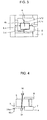
- FIG. 3 is a diagram showing distances between the wire electrode and the jig or the workpiece table in the individual directions as viewed from above.
- FIG. 9 is a flowchart showing processing for selecting the surfaces to be checked in the processing of Step SA12 of FIG. 8B . The following is a sequential description of steps in this flowchart.
- the following is a description of processing performed by a personal computer having the function of virtually performing electric discharge machining by the wire electric discharge machine or a controller having the function of virtually executing the machining program of the wire electric discharge machine.
- FIGS. 10A , 10B and 10C are flowcharts showing processing for making an interference (or collision) check during check drawing.
- Step SB01 It is determined whether or not the present function is effective. If the function is effective (YES), the processing proceeds to Step SB02. If not (NO), the processing proceeds to Step SB04.
- Step SB02 The region and thickness of the workpiece table are set, whereupon the processing proceeds to Step SB03.
- Data on the region and thickness of the workpiece table can be previously stored in the memory 12 by using the input means 14.
- Step SB03 The region and thickness of the jig are set, whereupon the processing proceeds to Step SB04.
- Data on the jig can be previously stored in the memory 12 by using the input means 14.
- Step SB04 A wire diameter compensation amount is set.
- Step SB05 A program surface height and a workpiece thickness are set. These values may be set by using parameters previously stored in the controller or set in a program.
- Step SB07 Virtual execution of the machining program is started.
- Step SB08 One block of the program is read and its execution is started.
- Step SB10 Selection of a surface to be checked is executed.
- Step SB13 Interference between the wire electrode and the surface to be checked is checked.
- Step SB17 Minimum movable distances in the four directions are updated.
- the minimum distances for the four directions (+X, -X, +Y, and -Y directions), out of the distances from the objects of interference obtained for the individual blocks of the machining program in Step SB16, and their directions are updated.
- Step SB19 It is determined whether or not the present function is effective. If the function is effective (YES), the processing proceeds to Step SB20. If not (NO), the processing proceeds to Step SB21.
- Step SB20 The data obtained in Step SB17, that is, the safe distances in the four directions, are output.
- Step SB22 It is determined whether or not an erroneous machining alarm is issued. If the erroneous machining alarm is issued (YES), the processing proceeds to Step SB23. If not (NO), the processing proceeds to Step SB24.
- Step SB23 Instruction to review the machining position is given.
- Step SB24 The safe distances in the four directions are confirmed and instruction to review the machining position is given, whereupon the processing ends.
Landscapes
- Engineering & Computer Science (AREA)
- Mechanical Engineering (AREA)
- Chemical & Material Sciences (AREA)
- Chemical Kinetics & Catalysis (AREA)
- Electrochemistry (AREA)
- Human Computer Interaction (AREA)
- Manufacturing & Machinery (AREA)
- Physics & Mathematics (AREA)
- General Physics & Mathematics (AREA)
- Automation & Control Theory (AREA)
- Electrical Discharge Machining, Electrochemical Machining, And Combined Machining (AREA)
- Numerical Control (AREA)
Abstract
Description
- The present invention relates to a wire electric discharge machine, and more particularly, to a wire electric discharge machine having an erroneous machining preventing function.
- In a wire electric discharge machine, a wire electrode is stretched and driven between upper and lower wire guides, and electric discharge machining is performed by applying voltage between the wire electrode and a workpiece disposed between the upper and lower wire guides (see Japanese Patent Application Laid-Open No.
2003-71636 -
FIG. 11 is a diagram showing how stroke limits are set so that upper and lower nozzles do not interfere (or collide) with a workpiece table, jig, or wall surfaces of a machining tank, in a wire electric discharge machine. Aworkpiece 5 is placed on a workpiece table 7 and secured to the table 7 by ajig 6. The workpiece table 7 is moved within a plane defined by X- and Y-axes by driving means (not shown). - An
upper nozzle 30 and alower nozzle 31 are disposed apart from each other above and below the workpiece table 7. An upper guide (not shown) supporting awire electrode 32 is mounted in theupper nozzle 30. A lower guide (not shown) supporting the wire electrode is mounted in thelower nozzle 31. U-axis extends in the same direction as the X-axis, while V-axis extends in the same direction as the Y-axis. Theupper nozzle 30 moves within a plane (upper guide plane) defined by the U- and V-axes and extending parallel to the plane defined by the X- and Y-axes. The upper nozzle 30 (upper guide) can move in the direction of Z-axis perpendicular to the plane defined by the X-and Y-axes (plane defined by the U- and V-axes). If thelower nozzle 31 moves, it moves within a lower guide plane parallel to the plane defined by the X- and Y-axes. - In the wire electric discharge machine, the
wire electrode 32 performs electric discharge machining in such a manner that it is run between the upper guide in theupper nozzle 30 and the lower guide in thelower nozzle 31, or the workpiece table 7 and theupper nozzle 30 are moved relative to thewire electrode 32, or theupper nozzle 30 is moved in the U- and V-axis directions. The wire electric discharge machine can perform workpiece tapering with the use of driving means for the X- and Y-axis directions and driving means for the U- and V-axis directions. - In the wire electric discharge machine, the stroke limits are set so that the upper and
lower nozzles jig 6, or machiningtank wall surfaces 9. The stroke limits individually set for the X-, Y-, U-, and V-axis directions will be referred to as anX-axis stroke limit 33, Y-axis stroke limit 34,U-axis stroke limit 35, and V-axis stroke limit 36, respectively. -
FIGS. 12A and 12B are diagrams illustrating problems of the conventional stroke limit setting method shown inFIG. 11 . - The U-axis
stroke limit 35 and the V-axis stroke limit 36 are named generically as a UV-axis stroke limit 40. Likewise, theX-axis stroke limit 33 and the Y-axis stroke limit 34 are named generically as an XY-axis stroke limit 41. The distance between anupper guide plane 37 and alower guide plane 38 is referred to as a guide-to-guide distance 42. Aprogram surface 39 and asub-program surface 47 are used as a reference for the creation of machining programs. - The stroke limits designate movable regions of the upper and
lower guide planes lower guide plane 38 is the maximum movable range of thelower nozzle 31 or the workpiece table 7 that is allowed in view of the machine configuration. On the other hand, theupper guide plane 37 is the maximum movable range of theupper nozzle 30 that is allowed in view of the machine configuration. - In taper machining, the operating range of the
wire electrode 32 varies depending on the program surface height, workpiece thickness, guide-to-guide distance, and taper angle. Possibly, therefore, the workpiece table 7 and/or thejig 6 may be erroneously machined during electric discharge machining in spite of care (seeFIG. 12A ). In the case of machining with theupper nozzle 30 inclined to the left ofFIG. 12A with respect to thelower nozzle 31, thewire electrode 32 interferes with neither thejig 6 nor the workpiece table 7. In the case of machining with theupper nozzle 30 inclined to the right ofFIG. 12A with respect to thelower nozzle 31, in contrast, thewire electrode 32 and thejig 6 may possibly interfere with each other although the upper andlower nozzles axis stroke limits - In some cases, moreover, a prohibited area may be established even in a range in which there is no interference during taper machining within the stroke limits, so that the operating range of the machine that is originally available for machining may fail to be used effectively (see
FIG. 12B ). Even when thelower nozzle 31 is moved further to the left of the XY-axis stroke limit 41, thewire electrode 32 interferes with neither thejig 6 nor the workpiece table 7. Thus, there is a problem that the operating range of the machine cannot be used effectively if the interference of thewire electrode 32 with thejig 6 or the workpiece table 7 within the stroke limits is checked based only on comparison with the stroke limits. - Accordingly, in view of the above-described problems of the prior art, the present invention has an object to provide a wire electric discharge machine capable of checking, during electric discharge machining, to see if there is interference (or collision) between a wire electrode and a workpiece table or a jig for securing a workpiece to the workpiece table, thereby preventing erroneous machining and effectively using its operating range.
- Another object of the present invention is to provide an arithmetic device capable of virtually executing a machining program for a wire electric discharge machine and checking to see if there is interference (or collision) between a wire electrode and a workpiece table or a jig for securing a workpiece to the workpiece table, thereby effectively using the operating range of the wire electric discharge machine.
- A wire electric discharge machine according to the present invention performs electric discharge machining on a workpiece by relatively moving the workpiece placed on a workpiece table and a wire electrode supported by upper and lower wire guides according to a machining program. The wire electric discharge machine comprises an interference determination unit configured to determine whether or not the top or bottom surface of the workpiece table interferes with the wire electrode at the height of the surface during the execution of the machining program.
- The interference determination unit may comprise a wire electrode position calculation section configured to calculate a position of the wire electrode on a plane at the height of the surface to be checked for interference with the wire electrode.
- The wire electric discharge machine may further comprise a jig configured to secure the workpiece to the workpiece table, and the interference determination unit may be configured to determine whether or not the top or bottom surface of the jig, in addition to the top or bottom surface of the workpiece table, interferes with the wire electrode at the height of the surface during the execution of the machining program.
- The interference determination unit may comprise a selection section configured to select one of the surfaces to be checked for interference with the wire electrode.
- The wire electric discharge machine may further comprise a setting unit configured to set a region and a thickness of the workpiece table.
- The wire electric discharge machine may further comprise a distance output unit configured to output minimums of distances between the wire electrode and the workpiece table in four directions including positive and negative first directions and positive and negative second directions perpendicular to the first directions.
- The wire electric discharge machine may further comprise a setting unit configured to set a region and a thickness of the jig for securing the workpiece to the workpiece table.
- The wire electric discharge machine may further comprise a distance output unit configured to output minimums of distances from the wire electrode to the workpiece table and the jig in four directions including positive and negative first directions and positive and negative second directions perpendicular to the first directions.
- An arithmetic device according to the present invention virtually executes a machining program for a wire electric discharge machine, which performs electric discharge machining on a workpiece by relatively moving the workpiece placed on a workpiece table and a wire electrode supported by upper and lower wire guides. The arithmetic device comprises an interference determination unit configured to determine whether or not the top or bottom surface of the workpiece table interferes with the wire electrode at the height of the surface during the virtual execution of the machining program.
- The interference determination unit may comprise a wire electrode position calculation section configured to calculate a position of the wire electrode on a plane at the height of the surface to be checked for interference with the wire electrode.
- The arithmetic device may further comprise a jig configured to secure the workpiece to the workpiece table, and the interference determination unit may be configured to determine whether or not the top or bottom surface of the jig, in addition to the top or bottom surface of the workpiece table, interferes with the wire electrode at the height of the surface during the virtual execution of the machining program.
- The interference determination unit may comprise a selection section configured to select one of the surfaces to be checked for interference with the wire electrode.
- The arithmetic device may further comprise a setting unit configured to set a region and a thickness of the workpiece table.
- The arithmetic device may further comprise a distance output unit configured to output minimums of distances between the wire electrode and the workpiece table in four directions including positive and negative first directions and positive and negative second directions perpendicular to the first directions.
- The arithmetic device may further comprise a setting unit configured to set a region and a thickness of the jig for securing the workpiece to the workpiece table.
- The arithmetic device may further comprise a distance output unit configured to output minimums of distances from the wire electrode to the workpiece table and the jig in four directions including positive and negative first directions and positive and negative second directions perpendicular to the first directions.
- According to the present invention, there can be provided a wire electric discharge machine capable of checking, during electric discharge machining, to see if there is interference (or collision) between a wire electrode and a workpiece table or a jig for securing a workpiece to the workpiece table, thereby preventing erroneous machining and effectively using its operating range.
- According to the present invention, moreover, there can be provided an arithmetic device capable of virtually executing a machining program for a wire electric discharge machine and checking to see if there is interference (or collision) between a wire electrode and a workpiece table or a jig for securing a workpiece to the workpiece table, thereby effectively using the operating range of the machine.
- The above and other objects and features of the present invention will be obvious from the ensuing description of embodiments with reference to the accompanying drawings, in which:
-
FIG. 1 is a diagram showing planes on which a limit check is made to prevent erroneous machining of a workpiece table and/or a jig during electric discharge machining; -
FIG. 2 is a diagram showing distances from a wire electrode to objects to be checked for interference (or collision) on individual surfaces to be checked; -
FIG. 3 is a diagram showing distances between the wire electrode and the jig or the workpiece table in individual directions as viewed from above; -
FIG. 4 is a diagram illustrating a case where the surfaces to be checked for interference (or collision) can be reduced; -
FIG. 5 is a diagram illustrating how to calculate wire electrode positions at the heights of the surfaces to be checked for interference (or collision); -
FIG. 6 is a diagram showing how to compensate the wire electrode diameter based on a discharge gap amount; -
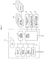
FIG. 7 is a schematic block diagram of a wire electric discharge machine controlled by a controller; -
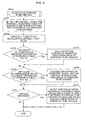
FIGS. 8A and8B are flowcharts showing processing for making an interference (or collision) check during actual machining; -
FIG. 9 is a flowchart showing processing for selecting the surfaces to be checked; -
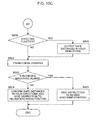
FIGS. 10A to 10C are flowcharts showing processing for making an interference (or collision) check during check drawing; -
FIG. 11 is a diagram showing how stroke limits are set so that upper and lower nozzles do not interfere (or collide) with a workpiece table, jig, or wall surfaces of a machining tank, in a wire electric discharge machine; and -
FIGS. 12A and 12B are diagram illustrating problems of the conventional stroke limit setting method shown inFIG. 11 . - An embodiment of the present invention will now be described with reference to the accompanying drawings. Like reference numerals are used to designate the same or similar configurations of the prior art and this embodiment.
- First, a method for checking interference of a wire electrode with a jig or a workpiece table in a wire electric discharge machine according to the present invention will be described with reference to
FIGS. 1, 2 and3 . -
FIG. 1 is a diagram showing planes on which a limit check is made to prevent erroneous machining of the workpiece table and/or the jig during electric discharge machining. - A
workpiece 5 may be secured to a workpiece table 7 by using a jig configured to hold theworkpiece 5 sideways, as well as by using thejig 6 shown inFIG. 11 . Further, theworkpiece 5 may be provided with a hole to which a bolt for fixing the workpiece table is attached. If the head portion of the bolt projects from the surface of theworkpiece 5, its projecting part may be handled as thejig 6. - In the electric discharge machine according to the present invention, as shown in
FIG. 1 , interference with awire electrode 32 is checked in each of regions including a jigtop surface 1, jig bottom surface (workpiece top surface) 2, workpiece table top surface (workpiece bottom surface) 3, and workpiece tablebottom surface 4, in addition to upper and lower guide planes 37 and 38. Specifically, erroneous machining of the workpiece table 7 and/or thejig 6 during the electric discharge machining is prevented by checking the interference of thewire electrode 32 with thejig 6 or the workpiece table 7, which may be caused as upper andlower nozzles - According to the interference checking method described above, the interference check need not always be made for all the four surfaces, including the jig
top surface 1, jigbottom surface 2, workpiece tabletop surface 3, and workpiece tablebottom surface 4, depending on the machining conditions. In this case, the calculation load can be reduced by reducing the number of surfaces to be checked for interference. The case where the surfaces to be checked for interference (or collision) can be reduced will now be described with reference toFIG. 4 . - Depending on the relative positions of the
lower nozzle 31 and the workpiece table 7 in the height direction, the workpiece tabletop surface 3 and the workpiece tablebottom surface 4 can be excluded from the group of surfaces to be checked for interference. In the case ofFIG. 4 , the height-direction position of thelower nozzle 31 is located above the bottom surface of the workpiece table 7 (workpiece table bottom surface 4), so that there is no possibility of thewire electrode 32 and the workpiece tablebottom surface 4 interfering with each other. In this case, therefore, the workpiece tablebottom surface 4 may be excluded from the group of surfaces to be checked for interference. If adistance 46 of atop height 31a of thelower nozzle 31 from the workpiece tabletop surface 3 is within a predetermined distance (e.g., 1 mm), moreover, the workpiece tabletop surface 3 may be excluded from the group of surfaces to be checked for interference. This is because thewire electrode 32 never interferes with the workpiece tabletop surface 3 due to the size of thelower nozzle 31. If thejig 6 is not used to secure theworkpiece 5 to the workpiece table 7, furthermore, thejig 6 and thewire electrode 32 need not be checked for mutual interference. -
FIG. 2 is a diagram showing distances from the wire electrode to the objects to be checked for interference (or collision) on the individual surfaces to be checked. - The distances from the
wire electrode 32 to thejig 6 and the workpiece table 7 are calculated for the individual regions including the jigtop surface 1, jigbottom surface 2, workpiece table top surface (workpiece bottom surface) 3, and workpiece tablebottom surface 4. The distances ("distance" will be defined later) from thewire electrode 32 to the jigtop surface 1, jigbottom surface 2, workpiece tabletop surface 3, and workpiece tablebottom surface 4 are calculated individually for four directions, +X direction, -X direction, +Y direction, and -Y direction. The +X direction and the -X direction orthogonally intersect the +Y direction and the -Y direction, respectively, on the workpiece tabletop surface 3. - The distances from the
wire electrode 32 to the jigtop surface 1, jigbottom surface 2, workpiece tabletop surface 3, and workpiece tablebottom surface 4 in the +X direction are designated by L+x(1), L+x(2), L+x(3) and L+x(4), respectively. - The distances from the
wire electrode 32 to the jigtop surface 1, jigbottom surface 2, workpiece tabletop surface 3, and workpiece tablebottom surface 4 in the -X direction are designated by L-x(1), L-x(2), L-x(3) and L-x(4), respectively. - The distances from the
wire electrode 32 to the jigtop surface 1, jigbottom surface 2, workpiece tabletop surface 3, and workpiece tablebottom surface 4 in the +Y direction are designated by L+y(1), L+y(2), L+y(3) and L+y(4), respectively. - The distances from the
wire electrode 32 to the jigtop surface 1, jigbottom surface 2, workpiece tabletop surface 3, and workpiece tablebottom surface 4 in the -Y direction are designated by L-y(1), L-y(2), L-y(3) and L-y(4), respectively. -
FIG. 3 is a diagram showing distances between the wire electrode and the jig or the workpiece table in the individual directions as viewed from above. - The minimum of the distances L+x(1), L+x(2), L+x(3) and L+x(4) from the
wire electrode 32 to the jigtop surface 1, jigbottom surface 2, workpiece tabletop surface 3, and workpiece tablebottom surface 4 in the +X direction is designated by L+x. - The minimum of the distances L-x(1), L-x(2), L-x(3) and L-x(4) from the
wire electrode 32 to the jigtop surface 1, jigbottom surface 2, workpiece tabletop surface 3, and workpiece tablebottom surface 4 in the -X direction is designated by L-x. - The minimum of the distances L+y(1), L+y(2), L+y(3) and L+y(4) from the
wire electrode 32 to the jigtop surface 1, jigbottom surface 2, workpiece tabletop surface 3, and workpiece tablebottom surface 4 in the +Y direction is designated by L+y. - The minimum of the distances L-y(1), L-y(2), L-y(3) and L-y(4) from the
wire electrode 32 to the jigtop surface 1, jigbottom surface 2, workpiece tabletop surface 3, and workpiece tablebottom surface 4 in the -Y direction is designated by L-y. - The position of a
machining path 45 of thewire electrode 32 can be reviewed by obtaining the distances L+x, L-x, L+y and L-y in the four directions (+X direction, -X direction, +Y direction, and -Y direction). Thereupon, the operating range of the machine can be used effectively. - The distances from the
wire electrode 32 to the jigtop surface 1, jigbottom surface 2, workpiece tabletop surface 3, and workpiece tablebottom surface 4 in each of the four directions (+X direction, -X direction, +Y direction, and -Y direction) are the minimums of the distances from thewire electrode 32 to the respective end portions of the individual regions including the jigtop surface 1, jigbottom surface 2, workpiece table top surface (workpiece bottom surface) 3, and workpiece tablebottom surface 4. Normally, thejig 6 and the workpiece table 7 are rectangular, so that the distances from thewire electrode 32 to each individual surface (the jigtop surface 1, jigbottom surface 2, workpiece tabletop surface 3, and workpiece table bottom surface 4) can be easily calculated as a length of one of the lines connecting thewire electrode 32 and each of two corner portions of a side of the each individual surface opposite thewire electrode 32, which is the shorter. -
FIG. 5 is a diagram illustrating how to calculate wire electrode positions at the heights of the surfaces to be checked for interference (or collision). - The positions of the
wire electrode 32 on each individual surface are calculated based on a position UV of theupper nozzle 30, position XY of thelower nozzle 31, height HL of thelower nozzle 31, and heights H1, H2, H3 and H4 of the jigtop surface 1, jigbottom surface 2, workpiece tabletop surface 3, and workpiece tablebottom surface 4. The position of theupper nozzle 30 on theupper guide plane 37 is represented by (U, V). The height above the origin of Z is represented by HU. - The position and height of the
wire electrode 32 on a plane at the same height as the jigtop surface 1 are represented by (X1, Y1) and H1, respectively. The position and height of thewire electrode 32 on a plane at the same height as thejig bottom surface 2 are represented by (X2, Y2) and H2, respectively. The position and height of thewire electrode 32 on a plane at the same height as the workpiece tabletop surface 3 are represented by (X3, Y3) and H3, respectively. The position and height of thewire electrode 32 on a plane at the same height as the workpiece tablebottom surface 4 are represented by (X4, Y4) and H4, respectively. The position and height of thelower nozzle 31 on thelower guide plane 38 are represented by (XL, YL) and HL, respectively. - The positions (X1, Y1), (X2, Y2), (X3, Y3), and (X4, Y4) of the
wire electrode 32 on the individual surfaces are calculated based on the position (U, V) of theupper nozzle 30 on theupper guide plane 37, position (XL, YL) of thelower nozzle 31 on thelower guide plane 38, height HU of theupper nozzle 30, and heights H1, H2, H3 and H4 of the jigtop surface 1, jigbottom surface 2, workpiece tabletop surface 3, and workpiece tablebottom surface 4. - In performing wire electric discharge machining on the
workpiece 5, a discharge gap is formed between thewire electrode 32 and theworkpiece 5. A machining error occurs if the discharge gap overlaps the regions in individual surfaces of thejig 6 or the workpiece table 7. Therefore, it is advisable to check the interference after compensating the diameter of thewire electrode 32. -
FIG. 6 is a diagram showing how to compensate the wire electrode diameter based on a discharge gap amount. - The sum total of the diameter of the
wire electrode 32 and the discharge gap amount is set to be a wire diameter compensation value. For the interference check on the jigtop surface 1, for example, the positions of points R1 (XR1, YR1) and L1 (XL1, YL1) at the right and left ends of a machining region on the jigtop surface 1 can be calculated based on the position (X1, Y1) of thewire electrode 32, a wire diameter compensation amount D, and the inclination of thewire electrode 32. If the calculated points R1 and L1 are within the region of thejig 6, it can be determined that there is interference. -
FIG. 7 is a schematic block diagram of the wire electric discharge machine controlled by a controller. - A
controller 10 for the wire electric discharge machine comprises a processor (CPU) 11, andmemory 12 formed of a ROM, RAM, etc.,display device 13 such as a liquid crystal display, input means 14 formed of a keyboard or a control panel, and axis control means 16 for controlling X-, Y-, Z-, U-, and V-axes, which are connected to theprocessor 11 through aninterface 18. Each axis control means 16 outputs a command for driving aservomotor 21 for each corresponding axis to aservo amplifier 20 for each corresponding axis. Further, thecontroller 10 comprises an input-output circuit 17 for commanding apower supply circuit 22, automaticwire connection device 23, and wireelectrode supply device 24. -
FIGS. 8A and8B are flowcharts showing processing for making an interference (or collision) check during actual machining. The following is a sequential description of steps in this flowchart. - [Step SA01] It is determined whether or not the present function is effective. If the function is effective (YES), the processing proceeds to Step SA02. If not (NO), the processing proceeds to Step SA03.
- [Step SA02] The region and thickness of the workpiece table are set, whereupon the processing proceeds to Step SA03. Data on the region and thickness of the workpiece table can be previously stored in the
memory 12 by using the input means 14. - [Step SA03] Instruction to place the workpiece on the workpiece table is given.
- [Step SA04] Instruction to secure the workpiece by the jig is given.
- [Step SA05] It is determined whether or not the present function is effective. If the function is effective (YES), the processing proceeds to Step SA06. If not (NO), the processing proceeds to Step SA07.
- [Step SA06] The region and thickness of the jig are set, whereupon the processing proceeds to Step SA07. Data on the region and thickness of the jig can be previously stored in the
memory 12 by using the input means 14. - [Step SA07] A wire diameter compensation amount is set.
- [Step SA08] A program surface height and a workpiece thickness are set. These values may be set by using parameters previously stored in the controller or set in a program.
- [Step SA09] Execution of a machining program is started.
- [Step SA10] One block of the program is read and executed.
- [Step SA11] It is determined whether or not the present function is effective. If the function is effective (YES), the processing proceeds to Step SA12. If not (NO), the processing proceeds to Step SA20.
- [Step SA12] Selection of a surface to be checked is executed.
- [Step SA13] The height of the surface to be checked is calculated.
- [Step SA14] The position of the wire electrode at the height of the surface to be checked is calculated.
- [Step SA15] Interference between the wire electrode and the surface to be checked is checked.
- [Step SA16] It is determined whether or not there is interference between the wire electrode and the surface to be checked. If there is the interference (YES), the processing proceeds to Step SA17. If not (NO), the processing proceeds to Step SA18.
- [Step SA17] An alarm indicative of the occurrence of erroneous machining is output, whereupon the processing proceeds to Step SA21.
- [Step SA18] Safe distances and directions are calculated. In this case, the distances between the wire electrode and the objects to be checked are obtained.
- [Step SA19] Minimum movable distances in the four directions (+X, -X, +Y, and -Y directions) are output. In this case, the minimum distances for the four directions, out of the distances from the objects of interference obtained for the individual blocks of the machining program in Step SA18, and their directions are obtained. The position of the machining path can be reviewed based on these data.
- [Step SA20] It is determined whether or not the execution of the program is finished. If the execution is not finished (NO), the processing proceeds to Step SA10. If the execution is finished (YES), the processing proceeds to Step SA21.
- [Step SA21] Program termination processing is performed, whereupon the electric discharge machining ends. The program termination processing includes power shutdown and the like.
-
FIG. 9 is a flowchart showing processing for selecting the surfaces to be checked in the processing of Step SA12 ofFIG. 8B . The following is a sequential description of steps in this flowchart. - [Step sa121] The jig
top surface 1, jigbottom surface 2, workpiece tabletop surface 3, and workpiece tablebottom surface 4 are set as surfaces to be checked. - [Step sa122] If the jig has a plurality of installation surfaces, the surfaces are increased. If the jig does not have a plurality of installation surfaces, processing of this step is not performed.
- [Step sa123] It is determined whether or not the top height of the lower nozzle is above the bottom surface of the workpiece table. If the top height is above the bottom surface of the workpiece table (YES), the processing proceeds to Step sa124. If not (NO), the processing proceeds to Step sa125.
- [Step sa124] The bottom surface of the workpiece table is excluded from the group of surfaces to be checked, whereupon the processing proceeds to Step sa125.
- [Step sa125] It is determined whether or not the top height of the lower nozzle is within 1 mm above the top surface of the workpiece table. If the top height is within 1 mm (YES), the processing proceeds to Step sa126. If not (NO), the processing proceeds to Step sa127.
- [Step sa126] The top surface of the workpiece table is excluded from the group of surfaces to be checked, whereupon the processing proceeds to Step sa127.
- [Step sa127] It is determined whether or not the machining is vertical machining. If the machining is vertical machining (YES), the processing proceeds to Step sa128. If not (NO), the processing for selecting the surface to be checked ends.
- [Step sa128] The surface on which the regions of the workpiece table and the jig are closest to the wire electrode is selected as the surface to be checked, and the other surfaces are excluded from the group of surfaces to be checked. Thereupon, the processing for selecting the surface to be checked ends.
- The following is a description of processing performed by a personal computer having the function of virtually performing electric discharge machining by the wire electric discharge machine or a controller having the function of virtually executing the machining program of the wire electric discharge machine.
-
FIGS. 10A ,10B and10C are flowcharts showing processing for making an interference (or collision) check during check drawing. - [Step SB01] It is determined whether or not the present function is effective. If the function is effective (YES), the processing proceeds to Step SB02. If not (NO), the processing proceeds to Step SB04.
- [Step SB02] The region and thickness of the workpiece table are set, whereupon the processing proceeds to Step SB03. Data on the region and thickness of the workpiece table can be previously stored in the
memory 12 by using the input means 14. - [Step SB03] The region and thickness of the jig are set, whereupon the processing proceeds to Step SB04. Data on the jig can be previously stored in the
memory 12 by using the input means 14. - [Step SB04] A wire diameter compensation amount is set.
- [Step SB05] A program surface height and a workpiece thickness are set. These values may be set by using parameters previously stored in the controller or set in a program.
- [Step SB06] Check drawing is started.
- [Step SB07] Virtual execution of the machining program is started.
- [Step SB08] One block of the program is read and its execution is started.
- [Step SB09] It is determined whether or not the present function is effective. If the function is effective (YES), the processing proceeds to Step SB10. If not (NO), the processing proceeds to Step SB18.
- [Step SB10] Selection of a surface to be checked is executed.
- [Step SB11] The height of the surface to be checked is calculated.
- [Step SB12] The position of the wire electrode at the height of the surface to be checked is calculated.
- [Step SB13] Interference between the wire electrode and the surface to be checked is checked.
- [Step SB14] It is determined whether or not there is interference between the wire electrode and the surface to be checked. If there is the interference (YES), the processing proceeds to Step SB15. If not (NO), the processing proceeds to Step SB16.
- [Step SB15] An alarm indicative of the occurrence of erroneous machining is output, whereupon this processing ends.
- [Step SB16] Safe distances and directions are calculated.
- [Step SB17] Minimum movable distances in the four directions are updated. In Step SB17, the minimum distances for the four directions (+X, -X, +Y, and -Y directions), out of the distances from the objects of interference obtained for the individual blocks of the machining program in Step SB16, and their directions are updated.
- [Step SB18] It is determined whether or not the execution of the program is finished. If the execution is not finished (NO), the processing proceeds to Step SB08. If the execution is finished (YES), the processing proceeds to Step SB19.
- [Step SB19] It is determined whether or not the present function is effective. If the function is effective (YES), the processing proceeds to Step SB20. If not (NO), the processing proceeds to Step SB21.
- [Step SB20] The data obtained in Step SB17, that is, the safe distances in the four directions, are output.
- [Step SB21] The check drawing is finished.
- [Step SB22] It is determined whether or not an erroneous machining alarm is issued. If the erroneous machining alarm is issued (YES), the processing proceeds to Step SB23. If not (NO), the processing proceeds to Step SB24.
- [Step SB23] Instruction to review the machining position is given.
- [Step SB24] The safe distances in the four directions are confirmed and instruction to review the machining position is given, whereupon the processing ends.
- According to the embodiment of the present invention described above, erroneous machining of the workpiece table and/or the jig can be prevented during machining. The wire electrode positions on the surfaces to be checked are calculated and it is checked to see if the wire electrode is within the regions of the jig and the workpiece table. Therefore, the check can be made in real time with a smaller calculation load than in a three-dimensional interference check. Thus, new solid data on the wire electrode need not be defined for the interference check. The occurrence of erroneous machining can be ascertained during the check drawing in virtually executing the machining program. Thus, interruptions during machining are reduced, so that the machining time can be reduced. According to the present invention, moreover, machining can be performed in a wider range than in the prior art, so that the operating range of the machine can be used effectively.
Claims (16)
- A wire electric discharge machine which performs electric discharge machining on a workpiece by relatively moving the workpiece placed on a workpiece table and a wire electrode supported by upper and lower wire guides according to a machining program, the wire electric discharge machine comprising:an interference determination unit configured to determine whether or not the top or bottom surface of the workpiece table interferes with the wire electrode at the height of the surface during the execution of the machining program.
- The wire electric discharge machine according to claim 1, wherein the interference determination unit comprises a wire electrode position calculation section configured to calculate a position of the wire electrode on a plane at the height of the surface to be checked for interference with the wire electrode.
- The wire electric discharge machine according to claim 1 or 2, further comprising a jig configured to secure the workpiece to the workpiece table, wherein the interference determination unit is configured to determine whether or not the top or bottom surface of the jig, in addition to the top or bottom surface of the workpiece table, interferes with the wire electrode at the height of the surface during the execution of the machining program.
- The wire electric discharge machine according to any one of claims 1 to 3, wherein the interference determination unit comprises a selection section configured to select one of the surfaces to be checked for interference with the wire electrode.
- The wire electric discharge machine according to claim 1, further comprising a setting unit configured to set a region and a thickness of the workpiece table.
- The wire electric discharge machine according to claim 1, further comprising a distance output unit configured to output minimums of distances between the wire electrode and the workpiece table in four directions including positive and negative first directions and positive and negative second directions perpendicular to the first directions.
- The wire electric discharge machine according to claim 3, further comprising a setting unit configured to set a region and a thickness of the jig for securing the workpiece to the workpiece table.
- The wire electric discharge machine according to claim 3 or 7, further comprising a distance output unit configured to output minimums of distances from the wire electrode to the workpiece table and the jig in four directions including positive and negative first directions and positive and negative second directions perpendicular to the first directions.
- An arithmetic device configured to virtually execute a machining program for a wire electric discharge machine, which performs electric discharge machining on a workpiece by relatively moving the workpiece placed on a workpiece table and a wire electrode supported by upper and lower wire guides, the arithmetic device comprising:an interference determination unit configured to determine whether or not the top or bottom surface of the workpiece table interferes with the wire electrode at the height of the surface during the virtual execution of the machining program.
- The arithmetic device according to claim 9, wherein the interference determination unit comprises a wire electrode position calculation section configured to calculate a position of the wire electrode on a plane at the height of the surface to be checked for interference with the wire electrode.
- The arithmetic device according to claim 9 or 10, further comprising a jig configured to secure the workpiece to the workpiece table, wherein the interference determination unit is configured to determine whether or not the top or bottom surface of the jig, in addition to the top or bottom surface of the workpiece table, interferes with the wire electrode at the height of the surface during the virtual execution of the machining program.
- The arithmetic device according to claim 11, wherein the interference determination unit comprises a selection section configured to select one of the surfaces to be checked for interference with the wire electrode.
- The arithmetic device according to claim 9, further comprising a setting unit configured to set a region and a thickness of the workpiece table.
- The arithmetic device according to claim 9, further comprising a distance output unit configured to output minimums of distances between the wire electrode and the workpiece table in four directions including positive and negative first directions and positive and negative second directions perpendicular to the first directions.
- The arithmetic device according to claim 11, further comprising a setting unit configured to set a region and a thickness of the jig for securing the workpiece to the workpiece table.
- The arithmetic device according to claim 11 or 15, further comprising a distance output unit configured to output minimums of distances from the wire electrode to the workpiece table and the jig in four directions including positive and negative first directions and positive and negative second directions perpendicular to the first directions.
Applications Claiming Priority (1)
| Application Number | Priority Date | Filing Date | Title |
|---|---|---|---|
| JP2014154973A JP5977290B2 (en) | 2014-07-30 | 2014-07-30 | Wire electrical discharge machine with function for preventing mis-machining |
Publications (3)
| Publication Number | Publication Date |
|---|---|
| EP2983052A2 true EP2983052A2 (en) | 2016-02-10 |
| EP2983052A3 EP2983052A3 (en) | 2016-07-06 |
| EP2983052B1 EP2983052B1 (en) | 2017-08-30 |
Family
ID=54065650
Family Applications (1)
| Application Number | Title | Priority Date | Filing Date |
|---|---|---|---|
| EP15176492.5A Active EP2983052B1 (en) | 2014-07-30 | 2015-07-13 | Wire electric discharge machine having erroneous machining preventing function |
Country Status (4)
| Country | Link |
|---|---|
| US (1) | US9956630B2 (en) |
| EP (1) | EP2983052B1 (en) |
| JP (1) | JP5977290B2 (en) |
| CN (1) | CN105312695B (en) |
Families Citing this family (8)
| Publication number | Priority date | Publication date | Assignee | Title |
|---|---|---|---|---|
| JP6126143B2 (en) * | 2015-01-20 | 2017-05-10 | ファナック株式会社 | Numerical control device with drawing path correction function |
| JP6162745B2 (en) * | 2015-05-13 | 2017-07-12 | ファナック株式会社 | Numerical control device with workpiece placement error correction function using machining start hole |
| JP6363567B2 (en) * | 2015-08-10 | 2018-07-25 | ファナック株式会社 | Numerical control device that limits the amount of movement in test operation near the stroke limit |
| US10272510B2 (en) * | 2016-01-14 | 2019-04-30 | United Technologies Corporation | Electrical discharge machining apparatus |
| JP6490118B2 (en) * | 2017-01-26 | 2019-03-27 | ファナック株式会社 | Numerical controller |
| JP6404968B2 (en) | 2017-03-03 | 2018-10-17 | ファナック株式会社 | Wire electric discharge machine |
| CN113708758B (en) * | 2020-05-20 | 2025-10-03 | 中兴通讯股份有限公司 | Phase detection method, device and equipment |
| CN117733259B (en) * | 2024-01-18 | 2025-03-14 | 池州市千润宇信息技术有限公司 | Linear cutting equipment |
Citations (1)
| Publication number | Priority date | Publication date | Assignee | Title |
|---|---|---|---|---|
| JP2003071636A (en) | 2001-08-30 | 2003-03-12 | Fanuc Ltd | Method and device for adjusting wire guide vertical position of wire cut electric discharge machine |
Family Cites Families (22)
| Publication number | Priority date | Publication date | Assignee | Title |
|---|---|---|---|---|
| JPS60213423A (en) * | 1984-04-07 | 1985-10-25 | Fanuc Ltd | Present position displaying method in wire-cut electric discharge machining device |
| JPS6384819A (en) * | 1986-09-29 | 1988-04-15 | Mitsubishi Electric Corp | Wire electric discharge machine |
| JPS63134124A (en) * | 1986-11-21 | 1988-06-06 | Mitsubishi Electric Corp | Wire electric discharge machine |
| JPH02180539A (en) * | 1988-11-14 | 1990-07-13 | Mitsubishi Electric Corp | Cad/cam device |
| JPH02152748A (en) * | 1988-12-02 | 1990-06-12 | Mitsubishi Electric Corp | Checking device for stroke end of machine tool for numerical control |
| CH690420A5 (en) * | 1995-05-11 | 2000-09-15 | Charmilles Technologies | Device for cut electric discharge machine. |
| JPH09212229A (en) * | 1996-01-30 | 1997-08-15 | Komatsu Ltd | Robot teaching device |
| JP2845848B2 (en) * | 1996-11-26 | 1999-01-13 | 日本電気ロボットエンジニアリング株式会社 | Wire electric discharge machine and taper machining method |
| JPH11165239A (en) * | 1997-12-05 | 1999-06-22 | Canon Inc | Numerical control data editing device and numerical control data editing method |
| JPH11170117A (en) * | 1997-12-11 | 1999-06-29 | Sodick Co Ltd | Controlling method and device for moving spindle of machine tool |
| JPH11221720A (en) * | 1998-02-06 | 1999-08-17 | Masuoka:Kk | Wire plumbing method for wire-cut electric discharge machine, and jig used therefor |
| DE19960834B4 (en) * | 1999-12-16 | 2006-10-26 | Agie S.A., Losone | Method and device for fault detection, in particular for collision detection, in the drive system of a numerically controlled machine tool |
| US6612043B2 (en) * | 2001-06-08 | 2003-09-02 | Industrial Technology Research Institute | Method and apparatus for vertically calibrating wire of wire cutting electric discharge machine |
| JP3946560B2 (en) * | 2002-04-02 | 2007-07-18 | 株式会社ソディック | Numerical control program creation method and numerical control electric discharge machining device |
| JP4353689B2 (en) * | 2002-10-25 | 2009-10-28 | 三菱電機メカトロニクスソフトウエア株式会社 | Method of creating machining path information in CAD / CAM apparatus and CAD / CAM apparatus |
| JP3985677B2 (en) * | 2002-12-25 | 2007-10-03 | 株式会社安川電機 | Apparatus and method for checking interference of horizontal articulated robot |
| ATE530283T1 (en) * | 2005-03-30 | 2011-11-15 | Agie Charmilles Sa | METHOD FOR MEASURING AND ADJUSTING AN ELECTRODE FOR CONE MACHINING USING A CUTTING WIRE SPARK EDM MACHINE |
| JP4904731B2 (en) * | 2005-07-06 | 2012-03-28 | 株式会社ジェイテクト | Interference check device for machine tools |
| JP5173510B2 (en) * | 2008-03-24 | 2013-04-03 | オークマ株式会社 | Processing simulation equipment |
| US8805570B2 (en) * | 2009-11-10 | 2014-08-12 | Mitsubishi Heavy Industries, Ltd. | Workpiece measuring device, collision preventing device, and machine tool |
| JP4938137B1 (en) * | 2011-03-03 | 2012-05-23 | ファナック株式会社 | Wire-cut electric discharge machine with a function to detect the upper surface of the workpiece |
| JP5226839B2 (en) * | 2011-08-17 | 2013-07-03 | ファナック株式会社 | Wire electrical discharge machine with positioning accuracy correction function |
-
2014
- 2014-07-30 JP JP2014154973A patent/JP5977290B2/en active Active
-
2015
- 2015-07-13 EP EP15176492.5A patent/EP2983052B1/en active Active
- 2015-07-28 US US14/810,536 patent/US9956630B2/en active Active
- 2015-07-30 CN CN201510461225.1A patent/CN105312695B/en active Active
Patent Citations (1)
| Publication number | Priority date | Publication date | Assignee | Title |
|---|---|---|---|---|
| JP2003071636A (en) | 2001-08-30 | 2003-03-12 | Fanuc Ltd | Method and device for adjusting wire guide vertical position of wire cut electric discharge machine |
Also Published As
| Publication number | Publication date |
|---|---|
| CN105312695A (en) | 2016-02-10 |
| JP5977290B2 (en) | 2016-08-24 |
| US9956630B2 (en) | 2018-05-01 |
| EP2983052A3 (en) | 2016-07-06 |
| CN105312695B (en) | 2018-01-09 |
| JP2016030323A (en) | 2016-03-07 |
| EP2983052B1 (en) | 2017-08-30 |
| US20160031025A1 (en) | 2016-02-04 |
Similar Documents
| Publication | Publication Date | Title |
|---|---|---|
| EP2983052B1 (en) | Wire electric discharge machine having erroneous machining preventing function | |
| EP2889100B1 (en) | Wire electric discharge machine and machining pass generating apparatus for wire electric discharge machine | |
| KR101485932B1 (en) | Method and device for generating tool path | |
| CN102809944B (en) | Numerical controller with function to correct movement path of machining program | |
| JP5108132B1 (en) | Wire electric discharge machine that performs taper machining by tilting the workpiece | |
| KR101735186B1 (en) | Machining program creating device for keyway milling for wire electric discharge machine | |
| EP2639003B1 (en) | Wire electric discharge machine controller for correcting machining route using program commands | |
| EP2495063B1 (en) | Wire-cut electric discharge machine having function of detecting upper surface of workpiece | |
| EP3023186A1 (en) | Wire electric discharge machine having corner shape correcting function | |
| JP6382865B2 (en) | Machining time prediction device | |
| EP2295180B1 (en) | Wire electric discharge machining method, apparatus therefor, wire electric discharge machining program creating device, and computer-readable recording medium in which program for creating wire electric discharge machining program is stored | |
| KR20130095762A (en) | Tool path generation method and tool path generation device | |
| JP5731613B2 (en) | Wire electric discharge machine and control device for wire electric discharge machine | |
| EP2002318B1 (en) | A method of under-sizing electrodes for polygonal orbit electrical discharge machining | |
| EP3196722B1 (en) | Machining time prediction device | |
| CN104281445B (en) | Can designated program perform step movement controller | |
| EP1755010A1 (en) | Movement controller for controlling movement of mobile body of machine tool, machine tool provided with movement controller and mobile body moving method | |
| EP3139232B1 (en) | Machining program creation apparatus for wire electrical discharge machiine | |
| JP6062973B2 (en) | Numerical control device capable of searching for nearby points in consideration of tool posture | |
| KR20180053234A (en) | Program generating apparatus | |
| JP5981012B2 (en) | Wire electric discharge machine with top and bottom independent corner shape correction function | |
| KR0178585B1 (en) | Corner processing method of wire cut electric discharge machine | |
| US20240126241A1 (en) | Numerical controller | |
| JPH0444281B2 (en) | ||
| JPH07246517A (en) | Jump control method for diesinking electrical discharge machine |
Legal Events
| Date | Code | Title | Description |
|---|---|---|---|
| PUAI | Public reference made under article 153(3) epc to a published international application that has entered the european phase |
Free format text: ORIGINAL CODE: 0009012 |
|
| AK | Designated contracting states |
Kind code of ref document: A2 Designated state(s): AL AT BE BG CH CY CZ DE DK EE ES FI FR GB GR HR HU IE IS IT LI LT LU LV MC MK MT NL NO PL PT RO RS SE SI SK SM TR |
|
| AX | Request for extension of the european patent |
Extension state: BA ME |
|
| PUAL | Search report despatched |
Free format text: ORIGINAL CODE: 0009013 |
|
| AK | Designated contracting states |
Kind code of ref document: A3 Designated state(s): AL AT BE BG CH CY CZ DE DK EE ES FI FR GB GR HR HU IE IS IT LI LT LU LV MC MK MT NL NO PL PT RO RS SE SI SK SM TR |
|
| AX | Request for extension of the european patent |
Extension state: BA ME |
|
| RIC1 | Information provided on ipc code assigned before grant |
Ipc: G05B 19/4097 20060101AFI20160530BHEP Ipc: G05B 19/4061 20060101ALI20160530BHEP Ipc: B23H 7/02 20060101ALI20160530BHEP Ipc: B23H 1/02 20060101ALI20160530BHEP |
|
| 17P | Request for examination filed |
Effective date: 20160926 |
|
| RBV | Designated contracting states (corrected) |
Designated state(s): AL AT BE BG CH CY CZ DE DK EE ES FI FR GB GR HR HU IE IS IT LI LT LU LV MC MK MT NL NO PL PT RO RS SE SI SK SM TR |
|
| GRAP | Despatch of communication of intention to grant a patent |
Free format text: ORIGINAL CODE: EPIDOSNIGR1 |
|
| RIC1 | Information provided on ipc code assigned before grant |
Ipc: B23H 1/02 20060101ALI20170222BHEP Ipc: G05B 19/4061 20060101ALI20170222BHEP Ipc: B23H 7/02 20060101ALI20170222BHEP Ipc: G05B 19/4097 20060101AFI20170222BHEP |
|
| INTG | Intention to grant announced |
Effective date: 20170321 |
|
| GRAS | Grant fee paid |
Free format text: ORIGINAL CODE: EPIDOSNIGR3 |
|
| GRAA | (expected) grant |
Free format text: ORIGINAL CODE: 0009210 |
|
| AK | Designated contracting states |
Kind code of ref document: B1 Designated state(s): AL AT BE BG CH CY CZ DE DK EE ES FI FR GB GR HR HU IE IS IT LI LT LU LV MC MK MT NL NO PL PT RO RS SE SI SK SM TR |
|
| REG | Reference to a national code |
Ref country code: GB Ref legal event code: FG4D |
|
| REG | Reference to a national code |
Ref country code: CH Ref legal event code: EP |
|
| REG | Reference to a national code |
Ref country code: AT Ref legal event code: REF Ref document number: 924161 Country of ref document: AT Kind code of ref document: T Effective date: 20170915 |
|
| REG | Reference to a national code |
Ref country code: IE Ref legal event code: FG4D |
|
| REG | Reference to a national code |
Ref country code: DE Ref legal event code: R096 Ref document number: 602015004408 Country of ref document: DE |
|
| REG | Reference to a national code |
Ref country code: CH Ref legal event code: NV Representative=s name: DR. LUSUARDI AG, CH |
|
| REG | Reference to a national code |
Ref country code: NL Ref legal event code: MP Effective date: 20170830 |
|
| REG | Reference to a national code |
Ref country code: LT Ref legal event code: MG4D |
|
| REG | Reference to a national code |
Ref country code: AT Ref legal event code: MK05 Ref document number: 924161 Country of ref document: AT Kind code of ref document: T Effective date: 20170830 |
|
| PG25 | Lapsed in a contracting state [announced via postgrant information from national office to epo] |
Ref country code: HR Free format text: LAPSE BECAUSE OF FAILURE TO SUBMIT A TRANSLATION OF THE DESCRIPTION OR TO PAY THE FEE WITHIN THE PRESCRIBED TIME-LIMIT Effective date: 20170830 Ref country code: SE Free format text: LAPSE BECAUSE OF FAILURE TO SUBMIT A TRANSLATION OF THE DESCRIPTION OR TO PAY THE FEE WITHIN THE PRESCRIBED TIME-LIMIT Effective date: 20170830 Ref country code: FI Free format text: LAPSE BECAUSE OF FAILURE TO SUBMIT A TRANSLATION OF THE DESCRIPTION OR TO PAY THE FEE WITHIN THE PRESCRIBED TIME-LIMIT Effective date: 20170830 Ref country code: LT Free format text: LAPSE BECAUSE OF FAILURE TO SUBMIT A TRANSLATION OF THE DESCRIPTION OR TO PAY THE FEE WITHIN THE PRESCRIBED TIME-LIMIT Effective date: 20170830 Ref country code: NO Free format text: LAPSE BECAUSE OF FAILURE TO SUBMIT A TRANSLATION OF THE DESCRIPTION OR TO PAY THE FEE WITHIN THE PRESCRIBED TIME-LIMIT Effective date: 20171130 Ref country code: AT Free format text: LAPSE BECAUSE OF FAILURE TO SUBMIT A TRANSLATION OF THE DESCRIPTION OR TO PAY THE FEE WITHIN THE PRESCRIBED TIME-LIMIT Effective date: 20170830 |
|
| PG25 | Lapsed in a contracting state [announced via postgrant information from national office to epo] |
Ref country code: IS Free format text: LAPSE BECAUSE OF FAILURE TO SUBMIT A TRANSLATION OF THE DESCRIPTION OR TO PAY THE FEE WITHIN THE PRESCRIBED TIME-LIMIT Effective date: 20171230 Ref country code: GR Free format text: LAPSE BECAUSE OF FAILURE TO SUBMIT A TRANSLATION OF THE DESCRIPTION OR TO PAY THE FEE WITHIN THE PRESCRIBED TIME-LIMIT Effective date: 20171201 Ref country code: RS Free format text: LAPSE BECAUSE OF FAILURE TO SUBMIT A TRANSLATION OF THE DESCRIPTION OR TO PAY THE FEE WITHIN THE PRESCRIBED TIME-LIMIT Effective date: 20170830 Ref country code: BG Free format text: LAPSE BECAUSE OF FAILURE TO SUBMIT A TRANSLATION OF THE DESCRIPTION OR TO PAY THE FEE WITHIN THE PRESCRIBED TIME-LIMIT Effective date: 20171130 Ref country code: ES Free format text: LAPSE BECAUSE OF FAILURE TO SUBMIT A TRANSLATION OF THE DESCRIPTION OR TO PAY THE FEE WITHIN THE PRESCRIBED TIME-LIMIT Effective date: 20170830 Ref country code: LV Free format text: LAPSE BECAUSE OF FAILURE TO SUBMIT A TRANSLATION OF THE DESCRIPTION OR TO PAY THE FEE WITHIN THE PRESCRIBED TIME-LIMIT Effective date: 20170830 |
|
| PG25 | Lapsed in a contracting state [announced via postgrant information from national office to epo] |
Ref country code: NL Free format text: LAPSE BECAUSE OF FAILURE TO SUBMIT A TRANSLATION OF THE DESCRIPTION OR TO PAY THE FEE WITHIN THE PRESCRIBED TIME-LIMIT Effective date: 20170830 |
|
| PG25 | Lapsed in a contracting state [announced via postgrant information from national office to epo] |
Ref country code: RO Free format text: LAPSE BECAUSE OF FAILURE TO SUBMIT A TRANSLATION OF THE DESCRIPTION OR TO PAY THE FEE WITHIN THE PRESCRIBED TIME-LIMIT Effective date: 20170830 Ref country code: DK Free format text: LAPSE BECAUSE OF FAILURE TO SUBMIT A TRANSLATION OF THE DESCRIPTION OR TO PAY THE FEE WITHIN THE PRESCRIBED TIME-LIMIT Effective date: 20170830 Ref country code: PL Free format text: LAPSE BECAUSE OF FAILURE TO SUBMIT A TRANSLATION OF THE DESCRIPTION OR TO PAY THE FEE WITHIN THE PRESCRIBED TIME-LIMIT Effective date: 20170830 Ref country code: CZ Free format text: LAPSE BECAUSE OF FAILURE TO SUBMIT A TRANSLATION OF THE DESCRIPTION OR TO PAY THE FEE WITHIN THE PRESCRIBED TIME-LIMIT Effective date: 20170830 |
|
| PG25 | Lapsed in a contracting state [announced via postgrant information from national office to epo] |
Ref country code: SM Free format text: LAPSE BECAUSE OF FAILURE TO SUBMIT A TRANSLATION OF THE DESCRIPTION OR TO PAY THE FEE WITHIN THE PRESCRIBED TIME-LIMIT Effective date: 20170830 Ref country code: IT Free format text: LAPSE BECAUSE OF FAILURE TO SUBMIT A TRANSLATION OF THE DESCRIPTION OR TO PAY THE FEE WITHIN THE PRESCRIBED TIME-LIMIT Effective date: 20170830 Ref country code: SK Free format text: LAPSE BECAUSE OF FAILURE TO SUBMIT A TRANSLATION OF THE DESCRIPTION OR TO PAY THE FEE WITHIN THE PRESCRIBED TIME-LIMIT Effective date: 20170830 Ref country code: EE Free format text: LAPSE BECAUSE OF FAILURE TO SUBMIT A TRANSLATION OF THE DESCRIPTION OR TO PAY THE FEE WITHIN THE PRESCRIBED TIME-LIMIT Effective date: 20170830 |
|
| REG | Reference to a national code |
Ref country code: DE Ref legal event code: R097 Ref document number: 602015004408 Country of ref document: DE |
|
| PLBE | No opposition filed within time limit |
Free format text: ORIGINAL CODE: 0009261 |
|
| STAA | Information on the status of an ep patent application or granted ep patent |
Free format text: STATUS: NO OPPOSITION FILED WITHIN TIME LIMIT |
|
| 26N | No opposition filed |
Effective date: 20180531 |
|
| PG25 | Lapsed in a contracting state [announced via postgrant information from national office to epo] |
Ref country code: SI Free format text: LAPSE BECAUSE OF FAILURE TO SUBMIT A TRANSLATION OF THE DESCRIPTION OR TO PAY THE FEE WITHIN THE PRESCRIBED TIME-LIMIT Effective date: 20170830 |
|
| PG25 | Lapsed in a contracting state [announced via postgrant information from national office to epo] |
Ref country code: LU Free format text: LAPSE BECAUSE OF NON-PAYMENT OF DUE FEES Effective date: 20180713 Ref country code: MC Free format text: LAPSE BECAUSE OF FAILURE TO SUBMIT A TRANSLATION OF THE DESCRIPTION OR TO PAY THE FEE WITHIN THE PRESCRIBED TIME-LIMIT Effective date: 20170830 |
|
| REG | Reference to a national code |
Ref country code: BE Ref legal event code: MM Effective date: 20180731 |
|
| REG | Reference to a national code |
Ref country code: IE Ref legal event code: MM4A |
|
| PG25 | Lapsed in a contracting state [announced via postgrant information from national office to epo] |
Ref country code: IE Free format text: LAPSE BECAUSE OF NON-PAYMENT OF DUE FEES Effective date: 20180713 Ref country code: FR Free format text: LAPSE BECAUSE OF NON-PAYMENT OF DUE FEES Effective date: 20180731 |
|
| PG25 | Lapsed in a contracting state [announced via postgrant information from national office to epo] |
Ref country code: BE Free format text: LAPSE BECAUSE OF NON-PAYMENT OF DUE FEES Effective date: 20180731 |
|
| PG25 | Lapsed in a contracting state [announced via postgrant information from national office to epo] |
Ref country code: MT Free format text: LAPSE BECAUSE OF NON-PAYMENT OF DUE FEES Effective date: 20180713 |
|
| GBPC | Gb: european patent ceased through non-payment of renewal fee |
Effective date: 20190713 |
|
| PG25 | Lapsed in a contracting state [announced via postgrant information from national office to epo] |
Ref country code: TR Free format text: LAPSE BECAUSE OF FAILURE TO SUBMIT A TRANSLATION OF THE DESCRIPTION OR TO PAY THE FEE WITHIN THE PRESCRIBED TIME-LIMIT Effective date: 20170830 |
|
| PG25 | Lapsed in a contracting state [announced via postgrant information from national office to epo] |
Ref country code: GB Free format text: LAPSE BECAUSE OF NON-PAYMENT OF DUE FEES Effective date: 20190713 |
|
| PG25 | Lapsed in a contracting state [announced via postgrant information from national office to epo] |
Ref country code: PT Free format text: LAPSE BECAUSE OF FAILURE TO SUBMIT A TRANSLATION OF THE DESCRIPTION OR TO PAY THE FEE WITHIN THE PRESCRIBED TIME-LIMIT Effective date: 20170830 |
|
| PG25 | Lapsed in a contracting state [announced via postgrant information from national office to epo] |
Ref country code: CY Free format text: LAPSE BECAUSE OF FAILURE TO SUBMIT A TRANSLATION OF THE DESCRIPTION OR TO PAY THE FEE WITHIN THE PRESCRIBED TIME-LIMIT Effective date: 20170830 Ref country code: MK Free format text: LAPSE BECAUSE OF NON-PAYMENT OF DUE FEES Effective date: 20170830 Ref country code: HU Free format text: LAPSE BECAUSE OF FAILURE TO SUBMIT A TRANSLATION OF THE DESCRIPTION OR TO PAY THE FEE WITHIN THE PRESCRIBED TIME-LIMIT; INVALID AB INITIO Effective date: 20150713 |
|
| PG25 | Lapsed in a contracting state [announced via postgrant information from national office to epo] |
Ref country code: AL Free format text: LAPSE BECAUSE OF FAILURE TO SUBMIT A TRANSLATION OF THE DESCRIPTION OR TO PAY THE FEE WITHIN THE PRESCRIBED TIME-LIMIT Effective date: 20170830 |
|
| REG | Reference to a national code |
Ref country code: DE Ref legal event code: R082 Ref document number: 602015004408 Country of ref document: DE Representative=s name: HL KEMPNER PATENTANWAELTE, SOLICITORS (ENGLAND, DE Ref country code: DE Ref legal event code: R082 Ref document number: 602015004408 Country of ref document: DE Representative=s name: HL KEMPNER PATENTANWALT, RECHTSANWALT, SOLICIT, DE Ref country code: DE Ref legal event code: R082 Ref document number: 602015004408 Country of ref document: DE Representative=s name: HL KEMPNER PARTG MBB, DE |
|
| PGFP | Annual fee paid to national office [announced via postgrant information from national office to epo] |
Ref country code: DE Payment date: 20250620 Year of fee payment: 11 |
|
| PGFP | Annual fee paid to national office [announced via postgrant information from national office to epo] |
Ref country code: CH Payment date: 20250801 Year of fee payment: 11 |