EP2983000B1 - Electrical storage device, electrical storage system, and electric vehicle - Google Patents
Electrical storage device, electrical storage system, and electric vehicle Download PDFInfo
- Publication number
- EP2983000B1 EP2983000B1 EP14779506.6A EP14779506A EP2983000B1 EP 2983000 B1 EP2983000 B1 EP 2983000B1 EP 14779506 A EP14779506 A EP 14779506A EP 2983000 B1 EP2983000 B1 EP 2983000B1
- Authority
- EP
- European Patent Office
- Prior art keywords
- power
- power storage
- storage device
- controller
- state
- Prior art date
- Legal status (The legal status is an assumption and is not a legal conclusion. Google has not performed a legal analysis and makes no representation as to the accuracy of the status listed.)
- Active
Links
Images


Classifications
-
- B—PERFORMING OPERATIONS; TRANSPORTING
- B60—VEHICLES IN GENERAL
- B60L—PROPULSION OF ELECTRICALLY-PROPELLED VEHICLES; SUPPLYING ELECTRIC POWER FOR AUXILIARY EQUIPMENT OF ELECTRICALLY-PROPELLED VEHICLES; ELECTRODYNAMIC BRAKE SYSTEMS FOR VEHICLES IN GENERAL; MAGNETIC SUSPENSION OR LEVITATION FOR VEHICLES; MONITORING OPERATING VARIABLES OF ELECTRICALLY-PROPELLED VEHICLES; ELECTRIC SAFETY DEVICES FOR ELECTRICALLY-PROPELLED VEHICLES
- B60L58/00—Methods or circuit arrangements for monitoring or controlling batteries or fuel cells, specially adapted for electric vehicles
- B60L58/10—Methods or circuit arrangements for monitoring or controlling batteries or fuel cells, specially adapted for electric vehicles for monitoring or controlling batteries
- B60L58/12—Methods or circuit arrangements for monitoring or controlling batteries or fuel cells, specially adapted for electric vehicles for monitoring or controlling batteries responding to state of charge [SoC]
- B60L58/15—Preventing overcharging
-
- B—PERFORMING OPERATIONS; TRANSPORTING
- B60—VEHICLES IN GENERAL
- B60L—PROPULSION OF ELECTRICALLY-PROPELLED VEHICLES; SUPPLYING ELECTRIC POWER FOR AUXILIARY EQUIPMENT OF ELECTRICALLY-PROPELLED VEHICLES; ELECTRODYNAMIC BRAKE SYSTEMS FOR VEHICLES IN GENERAL; MAGNETIC SUSPENSION OR LEVITATION FOR VEHICLES; MONITORING OPERATING VARIABLES OF ELECTRICALLY-PROPELLED VEHICLES; ELECTRIC SAFETY DEVICES FOR ELECTRICALLY-PROPELLED VEHICLES
- B60L1/00—Supplying electric power to auxiliary equipment of vehicles
- B60L1/02—Supplying electric power to auxiliary equipment of vehicles to electric heating circuits
- B60L1/04—Supplying electric power to auxiliary equipment of vehicles to electric heating circuits fed by the power supply line
- B60L1/06—Supplying electric power to auxiliary equipment of vehicles to electric heating circuits fed by the power supply line using only one supply
-
- B—PERFORMING OPERATIONS; TRANSPORTING
- B60—VEHICLES IN GENERAL
- B60L—PROPULSION OF ELECTRICALLY-PROPELLED VEHICLES; SUPPLYING ELECTRIC POWER FOR AUXILIARY EQUIPMENT OF ELECTRICALLY-PROPELLED VEHICLES; ELECTRODYNAMIC BRAKE SYSTEMS FOR VEHICLES IN GENERAL; MAGNETIC SUSPENSION OR LEVITATION FOR VEHICLES; MONITORING OPERATING VARIABLES OF ELECTRICALLY-PROPELLED VEHICLES; ELECTRIC SAFETY DEVICES FOR ELECTRICALLY-PROPELLED VEHICLES
- B60L15/00—Methods, circuits, or devices for controlling the traction-motor speed of electrically-propelled vehicles
- B60L15/20—Methods, circuits, or devices for controlling the traction-motor speed of electrically-propelled vehicles for control of the vehicle or its driving motor to achieve a desired performance, e.g. speed, torque, programmed variation of speed
- B60L15/2009—Methods, circuits, or devices for controlling the traction-motor speed of electrically-propelled vehicles for control of the vehicle or its driving motor to achieve a desired performance, e.g. speed, torque, programmed variation of speed for braking
-
- B—PERFORMING OPERATIONS; TRANSPORTING
- B60—VEHICLES IN GENERAL
- B60L—PROPULSION OF ELECTRICALLY-PROPELLED VEHICLES; SUPPLYING ELECTRIC POWER FOR AUXILIARY EQUIPMENT OF ELECTRICALLY-PROPELLED VEHICLES; ELECTRODYNAMIC BRAKE SYSTEMS FOR VEHICLES IN GENERAL; MAGNETIC SUSPENSION OR LEVITATION FOR VEHICLES; MONITORING OPERATING VARIABLES OF ELECTRICALLY-PROPELLED VEHICLES; ELECTRIC SAFETY DEVICES FOR ELECTRICALLY-PROPELLED VEHICLES
- B60L3/00—Electric devices on electrically-propelled vehicles for safety purposes; Monitoring operating variables, e.g. speed, deceleration or energy consumption
- B60L3/12—Recording operating variables ; Monitoring of operating variables
-
- B—PERFORMING OPERATIONS; TRANSPORTING
- B60—VEHICLES IN GENERAL
- B60L—PROPULSION OF ELECTRICALLY-PROPELLED VEHICLES; SUPPLYING ELECTRIC POWER FOR AUXILIARY EQUIPMENT OF ELECTRICALLY-PROPELLED VEHICLES; ELECTRODYNAMIC BRAKE SYSTEMS FOR VEHICLES IN GENERAL; MAGNETIC SUSPENSION OR LEVITATION FOR VEHICLES; MONITORING OPERATING VARIABLES OF ELECTRICALLY-PROPELLED VEHICLES; ELECTRIC SAFETY DEVICES FOR ELECTRICALLY-PROPELLED VEHICLES
- B60L50/00—Electric propulsion with power supplied within the vehicle
- B60L50/50—Electric propulsion with power supplied within the vehicle using propulsion power supplied by batteries or fuel cells
- B60L50/51—Electric propulsion with power supplied within the vehicle using propulsion power supplied by batteries or fuel cells characterised by AC-motors
-
- B—PERFORMING OPERATIONS; TRANSPORTING
- B60—VEHICLES IN GENERAL
- B60L—PROPULSION OF ELECTRICALLY-PROPELLED VEHICLES; SUPPLYING ELECTRIC POWER FOR AUXILIARY EQUIPMENT OF ELECTRICALLY-PROPELLED VEHICLES; ELECTRODYNAMIC BRAKE SYSTEMS FOR VEHICLES IN GENERAL; MAGNETIC SUSPENSION OR LEVITATION FOR VEHICLES; MONITORING OPERATING VARIABLES OF ELECTRICALLY-PROPELLED VEHICLES; ELECTRIC SAFETY DEVICES FOR ELECTRICALLY-PROPELLED VEHICLES
- B60L50/00—Electric propulsion with power supplied within the vehicle
- B60L50/50—Electric propulsion with power supplied within the vehicle using propulsion power supplied by batteries or fuel cells
- B60L50/52—Electric propulsion with power supplied within the vehicle using propulsion power supplied by batteries or fuel cells characterised by DC-motors
-
- B—PERFORMING OPERATIONS; TRANSPORTING
- B60—VEHICLES IN GENERAL
- B60L—PROPULSION OF ELECTRICALLY-PROPELLED VEHICLES; SUPPLYING ELECTRIC POWER FOR AUXILIARY EQUIPMENT OF ELECTRICALLY-PROPELLED VEHICLES; ELECTRODYNAMIC BRAKE SYSTEMS FOR VEHICLES IN GENERAL; MAGNETIC SUSPENSION OR LEVITATION FOR VEHICLES; MONITORING OPERATING VARIABLES OF ELECTRICALLY-PROPELLED VEHICLES; ELECTRIC SAFETY DEVICES FOR ELECTRICALLY-PROPELLED VEHICLES
- B60L50/00—Electric propulsion with power supplied within the vehicle
- B60L50/50—Electric propulsion with power supplied within the vehicle using propulsion power supplied by batteries or fuel cells
- B60L50/60—Electric propulsion with power supplied within the vehicle using propulsion power supplied by batteries or fuel cells using power supplied by batteries
- B60L50/61—Electric propulsion with power supplied within the vehicle using propulsion power supplied by batteries or fuel cells using power supplied by batteries by batteries charged by engine-driven generators, e.g. series hybrid electric vehicles
- B60L50/62—Electric propulsion with power supplied within the vehicle using propulsion power supplied by batteries or fuel cells using power supplied by batteries by batteries charged by engine-driven generators, e.g. series hybrid electric vehicles charged by low-power generators primarily intended to support the batteries, e.g. range extenders
-
- B—PERFORMING OPERATIONS; TRANSPORTING
- B60—VEHICLES IN GENERAL
- B60L—PROPULSION OF ELECTRICALLY-PROPELLED VEHICLES; SUPPLYING ELECTRIC POWER FOR AUXILIARY EQUIPMENT OF ELECTRICALLY-PROPELLED VEHICLES; ELECTRODYNAMIC BRAKE SYSTEMS FOR VEHICLES IN GENERAL; MAGNETIC SUSPENSION OR LEVITATION FOR VEHICLES; MONITORING OPERATING VARIABLES OF ELECTRICALLY-PROPELLED VEHICLES; ELECTRIC SAFETY DEVICES FOR ELECTRICALLY-PROPELLED VEHICLES
- B60L50/00—Electric propulsion with power supplied within the vehicle
- B60L50/50—Electric propulsion with power supplied within the vehicle using propulsion power supplied by batteries or fuel cells
- B60L50/60—Electric propulsion with power supplied within the vehicle using propulsion power supplied by batteries or fuel cells using power supplied by batteries
- B60L50/64—Constructional details of batteries specially adapted for electric vehicles
-
- B—PERFORMING OPERATIONS; TRANSPORTING
- B60—VEHICLES IN GENERAL
- B60L—PROPULSION OF ELECTRICALLY-PROPELLED VEHICLES; SUPPLYING ELECTRIC POWER FOR AUXILIARY EQUIPMENT OF ELECTRICALLY-PROPELLED VEHICLES; ELECTRODYNAMIC BRAKE SYSTEMS FOR VEHICLES IN GENERAL; MAGNETIC SUSPENSION OR LEVITATION FOR VEHICLES; MONITORING OPERATING VARIABLES OF ELECTRICALLY-PROPELLED VEHICLES; ELECTRIC SAFETY DEVICES FOR ELECTRICALLY-PROPELLED VEHICLES
- B60L53/00—Methods of charging batteries, specially adapted for electric vehicles; Charging stations or on-board charging equipment therefor; Exchange of energy storage elements in electric vehicles
- B60L53/60—Monitoring or controlling charging stations
- B60L53/65—Monitoring or controlling charging stations involving identification of vehicles or their battery types
-
- B—PERFORMING OPERATIONS; TRANSPORTING
- B60—VEHICLES IN GENERAL
- B60L—PROPULSION OF ELECTRICALLY-PROPELLED VEHICLES; SUPPLYING ELECTRIC POWER FOR AUXILIARY EQUIPMENT OF ELECTRICALLY-PROPELLED VEHICLES; ELECTRODYNAMIC BRAKE SYSTEMS FOR VEHICLES IN GENERAL; MAGNETIC SUSPENSION OR LEVITATION FOR VEHICLES; MONITORING OPERATING VARIABLES OF ELECTRICALLY-PROPELLED VEHICLES; ELECTRIC SAFETY DEVICES FOR ELECTRICALLY-PROPELLED VEHICLES
- B60L58/00—Methods or circuit arrangements for monitoring or controlling batteries or fuel cells, specially adapted for electric vehicles
- B60L58/10—Methods or circuit arrangements for monitoring or controlling batteries or fuel cells, specially adapted for electric vehicles for monitoring or controlling batteries
- B60L58/18—Methods or circuit arrangements for monitoring or controlling batteries or fuel cells, specially adapted for electric vehicles for monitoring or controlling batteries of two or more battery modules
- B60L58/19—Switching between serial connection and parallel connection of battery modules
-
- B—PERFORMING OPERATIONS; TRANSPORTING
- B60—VEHICLES IN GENERAL
- B60L—PROPULSION OF ELECTRICALLY-PROPELLED VEHICLES; SUPPLYING ELECTRIC POWER FOR AUXILIARY EQUIPMENT OF ELECTRICALLY-PROPELLED VEHICLES; ELECTRODYNAMIC BRAKE SYSTEMS FOR VEHICLES IN GENERAL; MAGNETIC SUSPENSION OR LEVITATION FOR VEHICLES; MONITORING OPERATING VARIABLES OF ELECTRICALLY-PROPELLED VEHICLES; ELECTRIC SAFETY DEVICES FOR ELECTRICALLY-PROPELLED VEHICLES
- B60L58/00—Methods or circuit arrangements for monitoring or controlling batteries or fuel cells, specially adapted for electric vehicles
- B60L58/10—Methods or circuit arrangements for monitoring or controlling batteries or fuel cells, specially adapted for electric vehicles for monitoring or controlling batteries
- B60L58/18—Methods or circuit arrangements for monitoring or controlling batteries or fuel cells, specially adapted for electric vehicles for monitoring or controlling batteries of two or more battery modules
- B60L58/20—Methods or circuit arrangements for monitoring or controlling batteries or fuel cells, specially adapted for electric vehicles for monitoring or controlling batteries of two or more battery modules having different nominal voltages
-
- B—PERFORMING OPERATIONS; TRANSPORTING
- B60—VEHICLES IN GENERAL
- B60L—PROPULSION OF ELECTRICALLY-PROPELLED VEHICLES; SUPPLYING ELECTRIC POWER FOR AUXILIARY EQUIPMENT OF ELECTRICALLY-PROPELLED VEHICLES; ELECTRODYNAMIC BRAKE SYSTEMS FOR VEHICLES IN GENERAL; MAGNETIC SUSPENSION OR LEVITATION FOR VEHICLES; MONITORING OPERATING VARIABLES OF ELECTRICALLY-PROPELLED VEHICLES; ELECTRIC SAFETY DEVICES FOR ELECTRICALLY-PROPELLED VEHICLES
- B60L58/00—Methods or circuit arrangements for monitoring or controlling batteries or fuel cells, specially adapted for electric vehicles
- B60L58/10—Methods or circuit arrangements for monitoring or controlling batteries or fuel cells, specially adapted for electric vehicles for monitoring or controlling batteries
- B60L58/18—Methods or circuit arrangements for monitoring or controlling batteries or fuel cells, specially adapted for electric vehicles for monitoring or controlling batteries of two or more battery modules
- B60L58/22—Balancing the charge of battery modules
-
- B—PERFORMING OPERATIONS; TRANSPORTING
- B60—VEHICLES IN GENERAL
- B60L—PROPULSION OF ELECTRICALLY-PROPELLED VEHICLES; SUPPLYING ELECTRIC POWER FOR AUXILIARY EQUIPMENT OF ELECTRICALLY-PROPELLED VEHICLES; ELECTRODYNAMIC BRAKE SYSTEMS FOR VEHICLES IN GENERAL; MAGNETIC SUSPENSION OR LEVITATION FOR VEHICLES; MONITORING OPERATING VARIABLES OF ELECTRICALLY-PROPELLED VEHICLES; ELECTRIC SAFETY DEVICES FOR ELECTRICALLY-PROPELLED VEHICLES
- B60L58/00—Methods or circuit arrangements for monitoring or controlling batteries or fuel cells, specially adapted for electric vehicles
- B60L58/10—Methods or circuit arrangements for monitoring or controlling batteries or fuel cells, specially adapted for electric vehicles for monitoring or controlling batteries
- B60L58/24—Methods or circuit arrangements for monitoring or controlling batteries or fuel cells, specially adapted for electric vehicles for monitoring or controlling batteries for controlling the temperature of batteries
- B60L58/26—Methods or circuit arrangements for monitoring or controlling batteries or fuel cells, specially adapted for electric vehicles for monitoring or controlling batteries for controlling the temperature of batteries by cooling
-
- B—PERFORMING OPERATIONS; TRANSPORTING
- B60—VEHICLES IN GENERAL
- B60L—PROPULSION OF ELECTRICALLY-PROPELLED VEHICLES; SUPPLYING ELECTRIC POWER FOR AUXILIARY EQUIPMENT OF ELECTRICALLY-PROPELLED VEHICLES; ELECTRODYNAMIC BRAKE SYSTEMS FOR VEHICLES IN GENERAL; MAGNETIC SUSPENSION OR LEVITATION FOR VEHICLES; MONITORING OPERATING VARIABLES OF ELECTRICALLY-PROPELLED VEHICLES; ELECTRIC SAFETY DEVICES FOR ELECTRICALLY-PROPELLED VEHICLES
- B60L58/00—Methods or circuit arrangements for monitoring or controlling batteries or fuel cells, specially adapted for electric vehicles
- B60L58/10—Methods or circuit arrangements for monitoring or controlling batteries or fuel cells, specially adapted for electric vehicles for monitoring or controlling batteries
- B60L58/24—Methods or circuit arrangements for monitoring or controlling batteries or fuel cells, specially adapted for electric vehicles for monitoring or controlling batteries for controlling the temperature of batteries
- B60L58/27—Methods or circuit arrangements for monitoring or controlling batteries or fuel cells, specially adapted for electric vehicles for monitoring or controlling batteries for controlling the temperature of batteries by heating
-
- B—PERFORMING OPERATIONS; TRANSPORTING
- B60—VEHICLES IN GENERAL
- B60L—PROPULSION OF ELECTRICALLY-PROPELLED VEHICLES; SUPPLYING ELECTRIC POWER FOR AUXILIARY EQUIPMENT OF ELECTRICALLY-PROPELLED VEHICLES; ELECTRODYNAMIC BRAKE SYSTEMS FOR VEHICLES IN GENERAL; MAGNETIC SUSPENSION OR LEVITATION FOR VEHICLES; MONITORING OPERATING VARIABLES OF ELECTRICALLY-PROPELLED VEHICLES; ELECTRIC SAFETY DEVICES FOR ELECTRICALLY-PROPELLED VEHICLES
- B60L7/00—Electrodynamic brake systems for vehicles in general
- B60L7/10—Dynamic electric regenerative braking
- B60L7/12—Dynamic electric regenerative braking for vehicles propelled by dc motors
-
- B—PERFORMING OPERATIONS; TRANSPORTING
- B60—VEHICLES IN GENERAL
- B60L—PROPULSION OF ELECTRICALLY-PROPELLED VEHICLES; SUPPLYING ELECTRIC POWER FOR AUXILIARY EQUIPMENT OF ELECTRICALLY-PROPELLED VEHICLES; ELECTRODYNAMIC BRAKE SYSTEMS FOR VEHICLES IN GENERAL; MAGNETIC SUSPENSION OR LEVITATION FOR VEHICLES; MONITORING OPERATING VARIABLES OF ELECTRICALLY-PROPELLED VEHICLES; ELECTRIC SAFETY DEVICES FOR ELECTRICALLY-PROPELLED VEHICLES
- B60L7/00—Electrodynamic brake systems for vehicles in general
- B60L7/10—Dynamic electric regenerative braking
- B60L7/14—Dynamic electric regenerative braking for vehicles propelled by ac motors
-
- G—PHYSICS
- G06—COMPUTING; CALCULATING OR COUNTING
- G06F—ELECTRIC DIGITAL DATA PROCESSING
- G06F1/00—Details not covered by groups G06F3/00 - G06F13/00 and G06F21/00
- G06F1/26—Power supply means, e.g. regulation thereof
- G06F1/263—Arrangements for using multiple switchable power supplies, e.g. battery and AC
-
- G—PHYSICS
- G06—COMPUTING; CALCULATING OR COUNTING
- G06F—ELECTRIC DIGITAL DATA PROCESSING
- G06F1/00—Details not covered by groups G06F3/00 - G06F13/00 and G06F21/00
- G06F1/26—Power supply means, e.g. regulation thereof
- G06F1/32—Means for saving power
-
- H—ELECTRICITY
- H01—ELECTRIC ELEMENTS
- H01M—PROCESSES OR MEANS, e.g. BATTERIES, FOR THE DIRECT CONVERSION OF CHEMICAL ENERGY INTO ELECTRICAL ENERGY
- H01M10/00—Secondary cells; Manufacture thereof
- H01M10/05—Accumulators with non-aqueous electrolyte
- H01M10/052—Li-accumulators
- H01M10/0525—Rocking-chair batteries, i.e. batteries with lithium insertion or intercalation in both electrodes; Lithium-ion batteries
-
- H—ELECTRICITY
- H01—ELECTRIC ELEMENTS
- H01M—PROCESSES OR MEANS, e.g. BATTERIES, FOR THE DIRECT CONVERSION OF CHEMICAL ENERGY INTO ELECTRICAL ENERGY
- H01M10/00—Secondary cells; Manufacture thereof
- H01M10/42—Methods or arrangements for servicing or maintenance of secondary cells or secondary half-cells
- H01M10/425—Structural combination with electronic components, e.g. electronic circuits integrated to the outside of the casing
- H01M10/4257—Smart batteries, e.g. electronic circuits inside the housing of the cells or batteries
-
- H—ELECTRICITY
- H01—ELECTRIC ELEMENTS
- H01M—PROCESSES OR MEANS, e.g. BATTERIES, FOR THE DIRECT CONVERSION OF CHEMICAL ENERGY INTO ELECTRICAL ENERGY
- H01M10/00—Secondary cells; Manufacture thereof
- H01M10/42—Methods or arrangements for servicing or maintenance of secondary cells or secondary half-cells
- H01M10/44—Methods for charging or discharging
-
- H—ELECTRICITY
- H02—GENERATION; CONVERSION OR DISTRIBUTION OF ELECTRIC POWER
- H02J—CIRCUIT ARRANGEMENTS OR SYSTEMS FOR SUPPLYING OR DISTRIBUTING ELECTRIC POWER; SYSTEMS FOR STORING ELECTRIC ENERGY
- H02J7/00—Circuit arrangements for charging or depolarising batteries or for supplying loads from batteries
- H02J7/0068—Battery or charger load switching, e.g. concurrent charging and load supply
-
- B—PERFORMING OPERATIONS; TRANSPORTING
- B60—VEHICLES IN GENERAL
- B60L—PROPULSION OF ELECTRICALLY-PROPELLED VEHICLES; SUPPLYING ELECTRIC POWER FOR AUXILIARY EQUIPMENT OF ELECTRICALLY-PROPELLED VEHICLES; ELECTRODYNAMIC BRAKE SYSTEMS FOR VEHICLES IN GENERAL; MAGNETIC SUSPENSION OR LEVITATION FOR VEHICLES; MONITORING OPERATING VARIABLES OF ELECTRICALLY-PROPELLED VEHICLES; ELECTRIC SAFETY DEVICES FOR ELECTRICALLY-PROPELLED VEHICLES
- B60L2210/00—Converter types
- B60L2210/10—DC to DC converters
- B60L2210/12—Buck converters
-
- B—PERFORMING OPERATIONS; TRANSPORTING
- B60—VEHICLES IN GENERAL
- B60L—PROPULSION OF ELECTRICALLY-PROPELLED VEHICLES; SUPPLYING ELECTRIC POWER FOR AUXILIARY EQUIPMENT OF ELECTRICALLY-PROPELLED VEHICLES; ELECTRODYNAMIC BRAKE SYSTEMS FOR VEHICLES IN GENERAL; MAGNETIC SUSPENSION OR LEVITATION FOR VEHICLES; MONITORING OPERATING VARIABLES OF ELECTRICALLY-PROPELLED VEHICLES; ELECTRIC SAFETY DEVICES FOR ELECTRICALLY-PROPELLED VEHICLES
- B60L2210/00—Converter types
- B60L2210/40—DC to AC converters
-
- B—PERFORMING OPERATIONS; TRANSPORTING
- B60—VEHICLES IN GENERAL
- B60L—PROPULSION OF ELECTRICALLY-PROPELLED VEHICLES; SUPPLYING ELECTRIC POWER FOR AUXILIARY EQUIPMENT OF ELECTRICALLY-PROPELLED VEHICLES; ELECTRODYNAMIC BRAKE SYSTEMS FOR VEHICLES IN GENERAL; MAGNETIC SUSPENSION OR LEVITATION FOR VEHICLES; MONITORING OPERATING VARIABLES OF ELECTRICALLY-PROPELLED VEHICLES; ELECTRIC SAFETY DEVICES FOR ELECTRICALLY-PROPELLED VEHICLES
- B60L2240/00—Control parameters of input or output; Target parameters
- B60L2240/10—Vehicle control parameters
- B60L2240/12—Speed
-
- B—PERFORMING OPERATIONS; TRANSPORTING
- B60—VEHICLES IN GENERAL
- B60L—PROPULSION OF ELECTRICALLY-PROPELLED VEHICLES; SUPPLYING ELECTRIC POWER FOR AUXILIARY EQUIPMENT OF ELECTRICALLY-PROPELLED VEHICLES; ELECTRODYNAMIC BRAKE SYSTEMS FOR VEHICLES IN GENERAL; MAGNETIC SUSPENSION OR LEVITATION FOR VEHICLES; MONITORING OPERATING VARIABLES OF ELECTRICALLY-PROPELLED VEHICLES; ELECTRIC SAFETY DEVICES FOR ELECTRICALLY-PROPELLED VEHICLES
- B60L2240/00—Control parameters of input or output; Target parameters
- B60L2240/40—Drive Train control parameters
- B60L2240/42—Drive Train control parameters related to electric machines
- B60L2240/421—Speed
-
- B—PERFORMING OPERATIONS; TRANSPORTING
- B60—VEHICLES IN GENERAL
- B60L—PROPULSION OF ELECTRICALLY-PROPELLED VEHICLES; SUPPLYING ELECTRIC POWER FOR AUXILIARY EQUIPMENT OF ELECTRICALLY-PROPELLED VEHICLES; ELECTRODYNAMIC BRAKE SYSTEMS FOR VEHICLES IN GENERAL; MAGNETIC SUSPENSION OR LEVITATION FOR VEHICLES; MONITORING OPERATING VARIABLES OF ELECTRICALLY-PROPELLED VEHICLES; ELECTRIC SAFETY DEVICES FOR ELECTRICALLY-PROPELLED VEHICLES
- B60L2240/00—Control parameters of input or output; Target parameters
- B60L2240/40—Drive Train control parameters
- B60L2240/44—Drive Train control parameters related to combustion engines
- B60L2240/441—Speed
-
- B—PERFORMING OPERATIONS; TRANSPORTING
- B60—VEHICLES IN GENERAL
- B60L—PROPULSION OF ELECTRICALLY-PROPELLED VEHICLES; SUPPLYING ELECTRIC POWER FOR AUXILIARY EQUIPMENT OF ELECTRICALLY-PROPELLED VEHICLES; ELECTRODYNAMIC BRAKE SYSTEMS FOR VEHICLES IN GENERAL; MAGNETIC SUSPENSION OR LEVITATION FOR VEHICLES; MONITORING OPERATING VARIABLES OF ELECTRICALLY-PROPELLED VEHICLES; ELECTRIC SAFETY DEVICES FOR ELECTRICALLY-PROPELLED VEHICLES
- B60L2240/00—Control parameters of input or output; Target parameters
- B60L2240/40—Drive Train control parameters
- B60L2240/54—Drive Train control parameters related to batteries
- B60L2240/547—Voltage
-
- B—PERFORMING OPERATIONS; TRANSPORTING
- B60—VEHICLES IN GENERAL
- B60L—PROPULSION OF ELECTRICALLY-PROPELLED VEHICLES; SUPPLYING ELECTRIC POWER FOR AUXILIARY EQUIPMENT OF ELECTRICALLY-PROPELLED VEHICLES; ELECTRODYNAMIC BRAKE SYSTEMS FOR VEHICLES IN GENERAL; MAGNETIC SUSPENSION OR LEVITATION FOR VEHICLES; MONITORING OPERATING VARIABLES OF ELECTRICALLY-PROPELLED VEHICLES; ELECTRIC SAFETY DEVICES FOR ELECTRICALLY-PROPELLED VEHICLES
- B60L2240/00—Control parameters of input or output; Target parameters
- B60L2240/40—Drive Train control parameters
- B60L2240/54—Drive Train control parameters related to batteries
- B60L2240/549—Current
-
- B—PERFORMING OPERATIONS; TRANSPORTING
- B60—VEHICLES IN GENERAL
- B60L—PROPULSION OF ELECTRICALLY-PROPELLED VEHICLES; SUPPLYING ELECTRIC POWER FOR AUXILIARY EQUIPMENT OF ELECTRICALLY-PROPELLED VEHICLES; ELECTRODYNAMIC BRAKE SYSTEMS FOR VEHICLES IN GENERAL; MAGNETIC SUSPENSION OR LEVITATION FOR VEHICLES; MONITORING OPERATING VARIABLES OF ELECTRICALLY-PROPELLED VEHICLES; ELECTRIC SAFETY DEVICES FOR ELECTRICALLY-PROPELLED VEHICLES
- B60L2250/00—Driver interactions
- B60L2250/16—Driver interactions by display
-
- G—PHYSICS
- G01—MEASURING; TESTING
- G01R—MEASURING ELECTRIC VARIABLES; MEASURING MAGNETIC VARIABLES
- G01R31/00—Arrangements for testing electric properties; Arrangements for locating electric faults; Arrangements for electrical testing characterised by what is being tested not provided for elsewhere
- G01R31/36—Arrangements for testing, measuring or monitoring the electrical condition of accumulators or electric batteries, e.g. capacity or state of charge [SoC]
- G01R31/382—Arrangements for monitoring battery or accumulator variables, e.g. SoC
-
- H—ELECTRICITY
- H01—ELECTRIC ELEMENTS
- H01M—PROCESSES OR MEANS, e.g. BATTERIES, FOR THE DIRECT CONVERSION OF CHEMICAL ENERGY INTO ELECTRICAL ENERGY
- H01M10/00—Secondary cells; Manufacture thereof
- H01M10/42—Methods or arrangements for servicing or maintenance of secondary cells or secondary half-cells
- H01M10/425—Structural combination with electronic components, e.g. electronic circuits integrated to the outside of the casing
- H01M2010/4271—Battery management systems including electronic circuits, e.g. control of current or voltage to keep battery in healthy state, cell balancing
-
- H—ELECTRICITY
- H01—ELECTRIC ELEMENTS
- H01M—PROCESSES OR MEANS, e.g. BATTERIES, FOR THE DIRECT CONVERSION OF CHEMICAL ENERGY INTO ELECTRICAL ENERGY
- H01M2220/00—Batteries for particular applications
- H01M2220/20—Batteries in motive systems, e.g. vehicle, ship, plane
-
- H—ELECTRICITY
- H02—GENERATION; CONVERSION OR DISTRIBUTION OF ELECTRIC POWER
- H02J—CIRCUIT ARRANGEMENTS OR SYSTEMS FOR SUPPLYING OR DISTRIBUTING ELECTRIC POWER; SYSTEMS FOR STORING ELECTRIC ENERGY
- H02J1/00—Circuit arrangements for dc mains or dc distribution networks
- H02J1/06—Two-wire systems
-
- H—ELECTRICITY
- H02—GENERATION; CONVERSION OR DISTRIBUTION OF ELECTRIC POWER
- H02J—CIRCUIT ARRANGEMENTS OR SYSTEMS FOR SUPPLYING OR DISTRIBUTING ELECTRIC POWER; SYSTEMS FOR STORING ELECTRIC ENERGY
- H02J2310/00—The network for supplying or distributing electric power characterised by its spatial reach or by the load
- H02J2310/40—The network being an on-board power network, i.e. within a vehicle
-
- H—ELECTRICITY
- H02—GENERATION; CONVERSION OR DISTRIBUTION OF ELECTRIC POWER
- H02J—CIRCUIT ARRANGEMENTS OR SYSTEMS FOR SUPPLYING OR DISTRIBUTING ELECTRIC POWER; SYSTEMS FOR STORING ELECTRIC ENERGY
- H02J7/00—Circuit arrangements for charging or depolarising batteries or for supplying loads from batteries
- H02J7/0063—Circuit arrangements for charging or depolarising batteries or for supplying loads from batteries with circuits adapted for supplying loads from the battery
-
- H—ELECTRICITY
- H02—GENERATION; CONVERSION OR DISTRIBUTION OF ELECTRIC POWER
- H02J—CIRCUIT ARRANGEMENTS OR SYSTEMS FOR SUPPLYING OR DISTRIBUTING ELECTRIC POWER; SYSTEMS FOR STORING ELECTRIC ENERGY
- H02J7/00—Circuit arrangements for charging or depolarising batteries or for supplying loads from batteries
- H02J7/007—Regulation of charging or discharging current or voltage
- H02J7/00712—Regulation of charging or discharging current or voltage the cycle being controlled or terminated in response to electric parameters
- H02J7/007182—Regulation of charging or discharging current or voltage the cycle being controlled or terminated in response to electric parameters in response to battery voltage
-
- Y—GENERAL TAGGING OF NEW TECHNOLOGICAL DEVELOPMENTS; GENERAL TAGGING OF CROSS-SECTIONAL TECHNOLOGIES SPANNING OVER SEVERAL SECTIONS OF THE IPC; TECHNICAL SUBJECTS COVERED BY FORMER USPC CROSS-REFERENCE ART COLLECTIONS [XRACs] AND DIGESTS
- Y02—TECHNOLOGIES OR APPLICATIONS FOR MITIGATION OR ADAPTATION AGAINST CLIMATE CHANGE
- Y02E—REDUCTION OF GREENHOUSE GAS [GHG] EMISSIONS, RELATED TO ENERGY GENERATION, TRANSMISSION OR DISTRIBUTION
- Y02E60/00—Enabling technologies; Technologies with a potential or indirect contribution to GHG emissions mitigation
- Y02E60/10—Energy storage using batteries
-
- Y—GENERAL TAGGING OF NEW TECHNOLOGICAL DEVELOPMENTS; GENERAL TAGGING OF CROSS-SECTIONAL TECHNOLOGIES SPANNING OVER SEVERAL SECTIONS OF THE IPC; TECHNICAL SUBJECTS COVERED BY FORMER USPC CROSS-REFERENCE ART COLLECTIONS [XRACs] AND DIGESTS
- Y02—TECHNOLOGIES OR APPLICATIONS FOR MITIGATION OR ADAPTATION AGAINST CLIMATE CHANGE
- Y02T—CLIMATE CHANGE MITIGATION TECHNOLOGIES RELATED TO TRANSPORTATION
- Y02T10/00—Road transport of goods or passengers
- Y02T10/60—Other road transportation technologies with climate change mitigation effect
- Y02T10/62—Hybrid vehicles
-
- Y—GENERAL TAGGING OF NEW TECHNOLOGICAL DEVELOPMENTS; GENERAL TAGGING OF CROSS-SECTIONAL TECHNOLOGIES SPANNING OVER SEVERAL SECTIONS OF THE IPC; TECHNICAL SUBJECTS COVERED BY FORMER USPC CROSS-REFERENCE ART COLLECTIONS [XRACs] AND DIGESTS
- Y02—TECHNOLOGIES OR APPLICATIONS FOR MITIGATION OR ADAPTATION AGAINST CLIMATE CHANGE
- Y02T—CLIMATE CHANGE MITIGATION TECHNOLOGIES RELATED TO TRANSPORTATION
- Y02T10/00—Road transport of goods or passengers
- Y02T10/60—Other road transportation technologies with climate change mitigation effect
- Y02T10/64—Electric machine technologies in electromobility
-
- Y—GENERAL TAGGING OF NEW TECHNOLOGICAL DEVELOPMENTS; GENERAL TAGGING OF CROSS-SECTIONAL TECHNOLOGIES SPANNING OVER SEVERAL SECTIONS OF THE IPC; TECHNICAL SUBJECTS COVERED BY FORMER USPC CROSS-REFERENCE ART COLLECTIONS [XRACs] AND DIGESTS
- Y02—TECHNOLOGIES OR APPLICATIONS FOR MITIGATION OR ADAPTATION AGAINST CLIMATE CHANGE
- Y02T—CLIMATE CHANGE MITIGATION TECHNOLOGIES RELATED TO TRANSPORTATION
- Y02T10/00—Road transport of goods or passengers
- Y02T10/60—Other road transportation technologies with climate change mitigation effect
- Y02T10/70—Energy storage systems for electromobility, e.g. batteries
-
- Y—GENERAL TAGGING OF NEW TECHNOLOGICAL DEVELOPMENTS; GENERAL TAGGING OF CROSS-SECTIONAL TECHNOLOGIES SPANNING OVER SEVERAL SECTIONS OF THE IPC; TECHNICAL SUBJECTS COVERED BY FORMER USPC CROSS-REFERENCE ART COLLECTIONS [XRACs] AND DIGESTS
- Y02—TECHNOLOGIES OR APPLICATIONS FOR MITIGATION OR ADAPTATION AGAINST CLIMATE CHANGE
- Y02T—CLIMATE CHANGE MITIGATION TECHNOLOGIES RELATED TO TRANSPORTATION
- Y02T10/00—Road transport of goods or passengers
- Y02T10/60—Other road transportation technologies with climate change mitigation effect
- Y02T10/7072—Electromobility specific charging systems or methods for batteries, ultracapacitors, supercapacitors or double-layer capacitors
-
- Y—GENERAL TAGGING OF NEW TECHNOLOGICAL DEVELOPMENTS; GENERAL TAGGING OF CROSS-SECTIONAL TECHNOLOGIES SPANNING OVER SEVERAL SECTIONS OF THE IPC; TECHNICAL SUBJECTS COVERED BY FORMER USPC CROSS-REFERENCE ART COLLECTIONS [XRACs] AND DIGESTS
- Y02—TECHNOLOGIES OR APPLICATIONS FOR MITIGATION OR ADAPTATION AGAINST CLIMATE CHANGE
- Y02T—CLIMATE CHANGE MITIGATION TECHNOLOGIES RELATED TO TRANSPORTATION
- Y02T10/00—Road transport of goods or passengers
- Y02T10/60—Other road transportation technologies with climate change mitigation effect
- Y02T10/72—Electric energy management in electromobility
-
- Y—GENERAL TAGGING OF NEW TECHNOLOGICAL DEVELOPMENTS; GENERAL TAGGING OF CROSS-SECTIONAL TECHNOLOGIES SPANNING OVER SEVERAL SECTIONS OF THE IPC; TECHNICAL SUBJECTS COVERED BY FORMER USPC CROSS-REFERENCE ART COLLECTIONS [XRACs] AND DIGESTS
- Y02—TECHNOLOGIES OR APPLICATIONS FOR MITIGATION OR ADAPTATION AGAINST CLIMATE CHANGE
- Y02T—CLIMATE CHANGE MITIGATION TECHNOLOGIES RELATED TO TRANSPORTATION
- Y02T10/00—Road transport of goods or passengers
- Y02T10/80—Technologies aiming to reduce greenhouse gasses emissions common to all road transportation technologies
- Y02T10/92—Energy efficient charging or discharging systems for batteries, ultracapacitors, supercapacitors or double-layer capacitors specially adapted for vehicles
-
- Y—GENERAL TAGGING OF NEW TECHNOLOGICAL DEVELOPMENTS; GENERAL TAGGING OF CROSS-SECTIONAL TECHNOLOGIES SPANNING OVER SEVERAL SECTIONS OF THE IPC; TECHNICAL SUBJECTS COVERED BY FORMER USPC CROSS-REFERENCE ART COLLECTIONS [XRACs] AND DIGESTS
- Y02—TECHNOLOGIES OR APPLICATIONS FOR MITIGATION OR ADAPTATION AGAINST CLIMATE CHANGE
- Y02T—CLIMATE CHANGE MITIGATION TECHNOLOGIES RELATED TO TRANSPORTATION
- Y02T90/00—Enabling technologies or technologies with a potential or indirect contribution to GHG emissions mitigation
- Y02T90/10—Technologies relating to charging of electric vehicles
- Y02T90/12—Electric charging stations
-
- Y—GENERAL TAGGING OF NEW TECHNOLOGICAL DEVELOPMENTS; GENERAL TAGGING OF CROSS-SECTIONAL TECHNOLOGIES SPANNING OVER SEVERAL SECTIONS OF THE IPC; TECHNICAL SUBJECTS COVERED BY FORMER USPC CROSS-REFERENCE ART COLLECTIONS [XRACs] AND DIGESTS
- Y02—TECHNOLOGIES OR APPLICATIONS FOR MITIGATION OR ADAPTATION AGAINST CLIMATE CHANGE
- Y02T—CLIMATE CHANGE MITIGATION TECHNOLOGIES RELATED TO TRANSPORTATION
- Y02T90/00—Enabling technologies or technologies with a potential or indirect contribution to GHG emissions mitigation
- Y02T90/10—Technologies relating to charging of electric vehicles
- Y02T90/14—Plug-in electric vehicles
-
- Y—GENERAL TAGGING OF NEW TECHNOLOGICAL DEVELOPMENTS; GENERAL TAGGING OF CROSS-SECTIONAL TECHNOLOGIES SPANNING OVER SEVERAL SECTIONS OF THE IPC; TECHNICAL SUBJECTS COVERED BY FORMER USPC CROSS-REFERENCE ART COLLECTIONS [XRACs] AND DIGESTS
- Y02—TECHNOLOGIES OR APPLICATIONS FOR MITIGATION OR ADAPTATION AGAINST CLIMATE CHANGE
- Y02T—CLIMATE CHANGE MITIGATION TECHNOLOGIES RELATED TO TRANSPORTATION
- Y02T90/00—Enabling technologies or technologies with a potential or indirect contribution to GHG emissions mitigation
- Y02T90/10—Technologies relating to charging of electric vehicles
- Y02T90/16—Information or communication technologies improving the operation of electric vehicles
- Y02T90/167—Systems integrating technologies related to power network operation and communication or information technologies for supporting the interoperability of electric or hybrid vehicles, i.e. smartgrids as interface for battery charging of electric vehicles [EV] or hybrid vehicles [HEV]
-
- Y—GENERAL TAGGING OF NEW TECHNOLOGICAL DEVELOPMENTS; GENERAL TAGGING OF CROSS-SECTIONAL TECHNOLOGIES SPANNING OVER SEVERAL SECTIONS OF THE IPC; TECHNICAL SUBJECTS COVERED BY FORMER USPC CROSS-REFERENCE ART COLLECTIONS [XRACs] AND DIGESTS
- Y04—INFORMATION OR COMMUNICATION TECHNOLOGIES HAVING AN IMPACT ON OTHER TECHNOLOGY AREAS
- Y04S—SYSTEMS INTEGRATING TECHNOLOGIES RELATED TO POWER NETWORK OPERATION, COMMUNICATION OR INFORMATION TECHNOLOGIES FOR IMPROVING THE ELECTRICAL POWER GENERATION, TRANSMISSION, DISTRIBUTION, MANAGEMENT OR USAGE, i.e. SMART GRIDS
- Y04S30/00—Systems supporting specific end-user applications in the sector of transportation
- Y04S30/10—Systems supporting the interoperability of electric or hybrid vehicles
- Y04S30/14—Details associated with the interoperability, e.g. vehicle recognition, authentication, identification or billing
Definitions
- the present disclosure relates to a power storage device, a power storage system, and an electric vehicle.
- Patent Literature 1 JP 2003-235155 A , US2005/077878 A1 (Carrier et al ), US2011/202220 A1 (Seta et al. ).
- Patent Literature 1 it is necessary to include a battery to operate the external controller. In order to dispense with the battery like this, it is desirable that the external controller provided in the external device be operated by the power to be supplied from the power storage device.
- one of purposes of the present disclosure is to provide a power storage device, a power storage system, and an electric vehicle in which an external controller provided in an external device is operated by the power to be supplied from the power storage device.
- the present disclosure is a power storage system including a first device and a second device .
- the first device includes a power storage unit which includes one or a plurality of cells, a first controller which performs control relating to the power storage unit, a first power line which supplies a first power output from the power storage unit to a load, a secondpower line which supplies a second power smaller than the first power to the second controller, and a communication line which is use by the first and second controllers to communicate with each other.
- the second device includes the load to which the first power is supplied via the first power line and the second controller to which the second power is supplied via the second power line and which communicates with the first controller via the communication line.
- the external controller provided in the external device is operated by the power to be supplied from the power storage device.
- the effect of this specification is an example, and the content of the present disclosure is not narrowly interpreted according to the exemplified effect.
- the expression “smaller than A” may be understood as “equal to or less than A” and “less than A” .
- the expression “larger than A” may be understood as “equal to or more than A” and “more than A”.
- the power storage device 2 includes a power storage unit 21 including one or a plurality of secondary battery cells (appropriately, referred to as cell) and a controller (appropriately, referred to as internal controller) 22 in the power storage device 2.
- a positive power line PL1 is connected to a positive side of the power storage unit 21, and a negative power line PL2 is connected to a negative side of the power storage unit 21.
- the power line PL1 is connected to the external device 3 via a positive electrode terminal 23.
- the power line PL2 is connected to the external device 3 via a negative electrode terminal 24.
- the internal controller 22 is operated by using the power output from the power storage unit 21.
- a state where the power is supplied to the load of the external device or a state where the external controller performs various processing in that state is appropriately referred to as an active state.
- a state where the power is not supplied to the load or a state where the external controller performs various processing in that state is appropriately referred to as a sleep state.
- the power consumption of the external device in the active state is larger than that of the external device in the sleep state.
- the power storage device 2 cannot recognize whether the external device 3 is in the active state or the sleep state. It is necessary for the power storage device 2 to continue to supply the output of the power storage unit 21 in order to prepare for a case where the state of the external device 3 becomes the active state. Therefore, it is necessary for the internal controller 22 in the power storage device 2 to strictly perform control relating to the power storage unit 21, for example, to prevent an overdischarge, cell balance control, temperature monitoring control, and current monitoring control.
- an exemplary secondary battery to be used is a lithium ion secondary battery including a positive-electrode active material and a carbon material such as graphite as a negative-electrode active material.
- a positive electrode material is not especially limited. However, the positive electrode material preferably includes a positive-electrode active material having an olivine structure.
- Transition element, IIA group element, IIIA group element, IIIB group element, IVB group element, and the like can be exemplified as M. It is especially preferable that M include at least one of cobalt (Co), nickel, manganese (Mn), iron, aluminum, vanadium (V), and titanium (Ti).
- a coating layer may be coated which includes metal oxide having different composition from that of the above oxide (for example, ones selected from among Ni, Mn, Li, and the like), phosphate compound (for example, lithium phosphate), and the like.
- the graphite in the present disclosure is not especially limited, and a graphite material which is used in the industry can be widely used.
- a material of the negative electrode lithium titanate, silicon (Si)-based material, tin (Sn)-based material, and the like may be used.
- the electric battery structure according to the present disclosure is not especially limited, and a well-known structure can be widely used.
- Electrolytic solution used in the present disclosure is not especially limited, and electrolytic solution, which includes liquid and gel-like electrolytic solution, used in the industry can be widely used.
- electrolyte solvent it is preferable to use 4-fluoro-1, 3-dioxolan-2-one (FEC), ethylene carbonate, propylene carbonate, butylene carbonate, vinylene carbonate (VC), dimethyl carbonate, diethyl carbonate, ethyl methyl carbonate, ⁇ -butyrolactone, ⁇ -valerolactone, 1, 2-dimethoxyethane, tetrahydrofuran, 2-methyltetrahydrofuran, 1, 3-dioxolane, 4-methyl-1, 3-dioxolane, methyl acetate, methyl propionate, ethyl propionate, acetonitrile, glutaronitrile, adiponitrile, methoxyacetonitrile, 3-methoxypropionitrile, N, N-dimethylformamide, N-methylpyrrolidone, N-methyloxazolidone, nitromethane, nitroethane, sulfolane, di
- FEC 4-fluoro-1, 3-dioxolan-2-one
- ethylene carbonate propylene carbonate
- butylene carbonate butylene carbonate
- vinylene carbonate VC
- dimethyl carbonate diethyl carbonate
- ethyl methyl carbonate diethyl carbonate
- ⁇ -butyrolactone ⁇ -valerolactone
- lithium hexafluorophosphate LiPF 6
- lithiumbis (pentafluoroethanesulfonyl) imide Li(C 2 F 5 SO 2 ) 2 N
- lithium perchlorate LiClO 4
- lithium hexafluoroarsenate LiAsF 6
- lithiumtetrafluoroborate LiBF 4
- lithiumtriflate LiSO 3 CF 3
- lithiumbis (trifluoromethanesulphonyl) imide Li (CF 3 SO 2 ) 2 N
- tris trifluoromethanesulfonyl) methyllithium
- a power storage device 100 is, for example, stored in an outer case having a predetermined shape. It is preferable that the outer case use a material having high conductivity and emissivity. Excellent heat radiation performance in the outer case can be obtained by using the material having the high conductivity and emissivity. Increase in the temperature in the outer case can be reduced by obtaining the excellent heat radiation performance. In addition, an opening of the outer case can be minimized or omitted, and high dust-proof and drip-proof can be realized. For the outer case, a material such as aluminum, aluminum alloy, copper, copper alloy, or the like is used. A detaching mechanism and the like according to a use of the power storage device 100 is formed on the outer case of the power storage device 100.
- the power storage device 100 includes a power storage unit including one or a plurality of cells.
- a power storage unit 103 includes three cells (cells CE1, CE2, and CE3).
- the cells CE1, CE2, and CE3 are connected in series.
- the number and a connection mode of the cells can be appropriately changed according to the use of the power storage device.
- the plurality of cells may be connected in parallel.
- the plurality of cells which is connected in parallel may be referred to as sub-module) may be connected in series.
- a positive power line PL105 is extended from a positive side of the cell CE1.
- a positive electrode terminal 110 is connected to the power line PL105.
- a negative power line PL106 is extended from a negative side of the cell CE3.
- a negative electrode terminal 111 is connected to the power line PL106.
- Power of the power storage unit 103 (example of first power) is supplied to an external device via the positive power line PL105 and the negative power line PL106. For example, a load of the external device is operated by using the first power.
- a state where the power storage device 100 supplies the first power via the positive electrode terminal 110 and the negative electrode terminal 111 relative to the external device or a state where an MCU to be described below performs predetermined processing in the above state is appropriately referred to as an active state .
- a state where the power storage device 100 supplies the second power via the S terminal 112 and the negative electrode terminal 111 relative to the external device or a state where the MCU to be described below performs the predetermined processing in the above state is appropriately referred to as a sleep state.
- the sleep state is an exemplary first state in claims
- the active state is an exemplary second state in claims.
- the power storage device 100 has a communication line SL109 used to communicate with the external device.
- a communication terminal (appropriately referred to as C terminal) 115 is connected to the communication line SL109.
- a duplex communication via the communication line SL109 based on the predetermined communication standard is performed between the power storage device 100 and the external device.
- a standard such as I2C and system management bus (SMBus) which are standards of the serial communication, serial peripheral interface (SPI) and CAN is exemplified.
- the wired and wireless communication may be performed.
- another communication line may be provided which is different from the communication line used for the communication based on the communication standard described above.
- the MCU 120 controls each unit of the power storage device 100.
- the MCU 120 performs, for example, control relating to the power storage unit 103.
- control relating to the power storage unit 103 control for monitoring the temperature and the voltage of each cell included in the power storage unit 103, a current which flows in the power storage unit 103, and the like, control for securing safety of the power storage device 100 to prevent overcurrent, over discharge, and the like, control for balancing the cells included in the power storage unit 103, and the like are exemplified.
- the MCU 120 When the power storage device 100 is in the active state, the MCU 120 strictly performs the control relating to the power storage unit 103. Whereas, when the power storage device 100 is in the sleep state, the MCU 120 does not strictly perform the control relating to the power storage unit 103. That is, the MCU 120 omits a part of the control relating to the power storage unit 103 performed in the active state, and a period of processing which is periodically performed is prolonged by the MCU 120. For example, when the power storage device 100 is in the sleep state, the MCU 120 monitors the remaining capacity (state of charge (SOC)) of the power storage unit 103 and the change of the state of the C terminal 115. Therefore, the power consumption of the MCU 120 in the sleep state is smaller than that of the MCU 120 in the active state.
- SOC state of charge
- the voltage multiplexer 121 outputs a voltage of each cell detected by a voltage detecting unit (not shown) to the ADC 122.
- the voltage of each cell is detected at a predetermined period during the charge and discharge. For example, when the power storage device 100 is in the active state, the voltage of each cell is detected by the voltage detecting unit at a period of 250 millisecond (ms). In this example, since the power storage unit 103 includes three cells, three analog voltage data is supplied to the voltage multiplexer 121.
- the voltage multiplexer 121 switches a channel at a predetermined period and selects a single analog voltage data from among the three analog voltage data.
- the single analog voltage data selected by the voltage multiplexer 121 is supplied to the ADC 122.
- the voltage multiplexer 121 switches the channel and supplies a next analog voltage data to the ADC 122.
- the switch of the channel by the voltage multiplexer 121 is controlled, for example, by the MCU 120.
- the temperature measuring unit 125 detects the temperature of each cell.
- the temperature measuring unit 125 includes an element to detect the temperature such as a thermistor. For example, the temperature of each cell is detected at the predetermined period during the charge and discharge .
- the highest temperature from among the three cells may be a temperature to be output from the temperature measuring unit 125, and an average value of the temperatures of the three cells may be a temperature to be output from the temperature measuring unit 125.
- the temperature multiplexer 130 switches the channel at the predetermined period and selects a single analog temperature data fromamong the three analog temperature data.
- the single analog temperature data selected by the temperature multiplexer 130 is supplied to the ADC 122.
- the temperature multiplexer 130 switches the channel and supplies a next analog temperature data to the ADC 122.
- the channel is switched by the temperature multiplexer 130, for example, according to the control by the MCU 120.
- the temperature measuring unit 128 measures the temperature of a whole power storage device 100.
- the temperature measuring unit 128 measures the temperature in the outer case of the power storage device 100.
- the analog temperature data measured by the temperature measuring unit 128 is supplied to the temperature multiplexer 130, and then, the analog temperature data is supplied from the temperature multiplexer 130 to the ADC 122.
- the ADC 122 converts the analog temperature data into a digital temperature data.
- the digital temperature data is supplied from the ADC 122 to the monitoring unit 123.
- the ADC 122 converts the analog voltage data supplied from the voltage multiplexer 121 into a digital voltage data.
- the ADC 122 converts the analog voltage data into, for example, a digital voltage data of 14 to 18 bits.
- various methods such as a successively comparing system and a delta sigma ( ⁇ ) system may be applied.
- the ADC 122 includes an input terminal, an output terminal, a control signal input terminal to which a control signal is input, and a clock pulse input terminal to which a clock pulse is input (these terminals are not shown) .
- the analog voltage data is input to the input terminal.
- the output terminal outputs the converted digital voltage data.
- a control signal (control command) supplied from the MCU 120 is input to the control signal input terminal.
- the control signal is, for example, an acquisition instructing signal which instructs to obtain the analog voltage data supplied from the voltage multiplexer 121.
- the ADC 122 obtains the analog voltage data, and the obtained analog voltage data is converted into the digital voltage data.
- the digital voltage data is output via the output terminal according to a clock pulse for synchronization to be input to the clock pulse input terminal.
- the output digital voltage data is supplied to the monitoring unit 123.
- the acquisition instructing signal which instructs to obtain the analog temperature data supplied from the temperature multiplexer 130 is input to the control signal input terminal.
- the ADC 122 obtains the analog temperature data according to the acquisition instructing signal.
- the ADC 122 converts the obtained analog temperature data into the digital temperature data.
- the analog temperature data is converted into, for example, a digital temperature data of 14 to 18 bits.
- the converted digital temperature data is output via the output terminal, and the output digital temperature data is supplied to the monitoring unit 123.
- ADCs which respectively perform processing to a voltage data and a temperature data may be separately provided.
- a function block of the ADC 122 may have a function of a comparator for comparing the voltage and temperature with a predetermined value.
- the current detecting resistor 132 detects values of currents for respectively flowing in the three cells.
- the current detecting resistor 132 detects an analog current data. For example, the analog current data is detected at a predetermined period during the charge and discharge.
- the current detecting amplifier 133 amplifies the detected analog current data.
- a gain of the current detecting amplifier 133 is set to, for example, about 50 to 100 times.
- the analog current data amplified by the current detecting amplifier 133 is supplied to the ADC 134.
- the ADC 134 converts the analog current data supplied from the current detecting amplifier 133 into a digital current data.
- the ADC 134 converts the analog current data into, for example, a digital current data of 14 to 18 bits.
- various methods such as a successively comparing system and a delta sigma ( ⁇ ) system can be applied.
- the ADC 134 includes an input terminal, an output terminal, a control signal input terminal to which a control signal is input, and a clock pulse input terminal to which a clock pulse is input (these terminals are not shown) .
- the analog current data is input to the input terminal.
- the output terminal outputs the digital current data.
- control signal (control command) supplied from the MCU 120 is input to the control signal input terminal of the ADC 134.
- the control signal is, for example, an acquisition instructing signal which instructs to obtain the analog current data supplied from the current detecting amplifier 133.
- acquisition instructing signal is input, the ADC 134 obtains the analog current data, and the obtained analog current data is converted into the digital current data.
- the digital current data is output from the output terminal according to the clock pulse for synchronization to be input to the clock pulse input terminal.
- the output digital current data is supplied to the monitoring unit 123.
- the ADC 122 may be the same as the ADC 134.
- the monitoring unit 123 outputs the digital voltage data and the digital temperature data supplied from the ADC 122 to the MCU 120. In addition, the monitoring unit 123 outputs the digital current data supplied from the ADC 134 to the MCU 120.
- the MCU 120 performs the control relating to the power storage unit 103 based on various data supplied from the monitoring unit 123.
- the warming unit 131 appropriately warms the cells .
- the warming unit 131 includes a resistance wire having a predetermined resistance value and is provided near the cells .
- the resistance wire is arranged so as to effectively warm the cells, and the current flows in the resistance wire. Accordingly, the cells are warmed.
- the MCU 120 controls the warming unit 131 (for example, turning on/off the warming unit 131).
- the regulator 139 is provided between the power line PL105 and the MCU 120.
- the regulator 139 is connected to a connection midpoint between the charging controller 144 and the discharging controller 145.
- the MCU 120 is connected to the connection midpoint between the charging controller 144 and the discharging controller 145 via the regulator 139.
- the regulator 139 forms an operating voltage (for example, 3.3 V or 5 V) of the MCU 120 from the voltage of the power storage unit 103 and supplies the formed operating voltage to the MCU 120. That is, the MCU 120 is operated by the power of the power storage unit 103.
- the S terminal 112 (power line PL107) is connected to an end of the regulator 139 where the power is output. However, the S terminal 112 may be connected to an end of the regulator 139 where the power is input.
- a storage unit 142 includes a read only memory (ROM), a random access memory (RAM), and the like.
- the storage unit 142 stores, for example, a program to be performed by the MCU 120.
- the storage unit 142 is used as a work area in a case where the MCU 120 performs the processing.
- the storage unit 142 may store histories of the charge and the discharge.
- the charging controller 144 includes a charge control switch 144a and a diode 144b.
- the diode 144b is connected to the charge control switch 144a in parallel and in the forward direction relative to a discharge current.
- the discharging controller 145 includes a discharge control switch 145a and a diode 145b.
- the diode 145b is connected to the discharge control switch 145a in parallel and in the forward direction relative to a charge current.
- an insulated gate bipolar transistor (IGBT) and a metal oxide semiconductor field effect transistor (MOSFET) can be used as the charge control switch 144a and the discharge control switch 145a.
- the charging controller 144 and the discharging controller 145 may be inserted to a negative power supply line.
- the FET1 and the FET3 are turned on, and the cells CE1 and CE3 are discharged to a predetermined voltage value.
- the FET1 and the FET3 are turned off after the discharge.
- the voltages of the respective cells after the discharge becomes, for example, a predetermined value (for example, 3.0 V), and the voltages of the respective cells are balanced.
- a system of the cell balance control is not limited to the passive system, and a so-called active method and other well-known method can be applied.
- the above-mentioned structure of the power storage device is an example. A part of the exemplified structure may be omitted, and a structure which is different from the exemplified structure may be added.
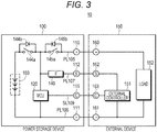
- FIG. 3 An exemplary operation of the power storage device 100 will be described with reference to Fig. 3 . Structures of the power storage device and the external device are simplified and illustrated in Fig. 3 .
- an external device 150 is connected to the power storage device 100.
- a power storage system 10 is formed by the power storage device 100 and the external device 150.
- the power storage device 100 may be fixed to the external device 150, and the power storage device 100 may be removable to the external device 150.
- the external device 150 has an external controller 151 including a central processing unit (CPU) and the like and a load 152.
- the external device 150 includes a positive electrode terminal 160, a negative electrode terminal 161, an S terminal 162, and a C terminal 163.
- the positive electrode terminal 160 is connected to the positive electrode terminal 110 of the power storage device 100.
- the negative electrode terminal 161 is connected to the negative electrode terminal 111 of the power storage device 100.
- the S terminal 162 is connected to the S terminal 112 of the power storage device 100.
- the C terminal 163 is connected to the C terminal 115 of the power storage device 100.
- the external device be a compact electric vehicle (EV) (electric automobile) and the load 152 be a motor.
- EV compact electric vehicle
- both of the power storage device 100 and the external device 150 are in the sleep state.
- the states (level) of the C terminal 115 and the C terminal 163 are high. Since it is not necessary to supply the power to the load 152, the charge control switch 144a and the discharge control switch 145a are turned off. The power of the power storage unit 103 is not supplied to the load 152.
- the external controller 151 is operated by using the power of the power storage unit 103.
- the power from the power storage unit 103 is supplied to the fuse (abbreviated as F in the figure) 140 via the diode 144b.
- the fuse 140 forms the second power.
- the second power is supplied to the S terminal 112.
- the power output from the S terminal 112 is supplied to the external controller 151 via the S terminal 162.
- the external controller 151 is operated based on the power to be supplied. In the sleep state, for example, the external controller 151 monitors whether the instruction to start the compact EV is made. Since the load 152 is not driven, it is not necessary for the external controller 151 to control the load 152.
- the load of the processing performed by the external controller 151 is small. Therefore, the power consumption by the external controller 151 is slight. Since the power consumption by the external controller 151 is slight, there is small effect on the remaining capacity and the temperature of the power storage unit 103. Therefore, the MCU 120 monitors the remaining capacity at a period longer than the normal period. Also, a part of the processing (for example, processing such as monitoring the temperature) is not performed. Accordingly, the power consumption of the MCU 120 can be reduced.
- the MCU 120 detects the change of the state of the C terminal 115.
- the MCU 120 which has detected that the state of the C terminal 115 has become low, changes its state from the sleep state to the active state and performs the processing according to the active state.
- the MCU 120 of which the state has changed to the active state performs, for example, processing for turning on at least the discharge control switch 145a (also, processing for turning on the charge control switch 144a may be performed) .
- the power of the power storage unit 103 is supplied to the load 152 via the power lines PL105 and PL106.
- the external controller 151 performs the control to drive the load 152.
- the load 152 is driven by the power of the power storage unit 103.
- the MCU 120 Since the power of the power storage unit 103 is supplied to the load 152, the MCU 120 strictly performs the control relating to the power storage unit 103. For example, the MCU 120 tries to safely operate the power storage device 100 by performing processing for monitoring an amount of the current flowing in the power storage unit 103 and monitoring the voltage and the temperature of each cell and processing to adjust the balance between the cells. Based on the result of the processing, the MCU 120 appropriately turns on/off the charge control switch 144a and the discharge control switch 145a and secures the safety of the power storage device 100. Well-known processing can be applied to the processing for securing the safety of the power storage device 100. For example, when the temperature of the cell is higher than a predetermined value and when the lowest voltage of the cell is lower than a predetermined voltage, the discharge control switch 145a is turned off.
- the external controller 151 detects the operation stop instruction.
- the external controller 151 changes its state from the active state to the sleep state and, for example, stops the drive of the load 152.
- the external controller 151 lowers the state of the C terminal 163 to high. Accordingly, the state of the C terminal 115 changes to high.
- the external controller 151 of which the state is changed to the sleep state monitors, for example, whether the starting instruction is input or not. For example, this monitoring processing is regularly performed.
- the MCU 120 detects the change of the state of the C terminal 115.
- the MCU 120 which has detected that the state of the C terminal 115 has become high, changes its state from the active state to the sleep state and performs the processing according to the sleep state.
- the MCU 120 of which the state has been changed to the sleep state for example, turns off the discharge control switch 145a and the charge control switch 144a and monitors the remaining capacity of each cell and the state of the C terminal. Accordingly, the supply of the power of the power storage unit 103 to the load 152 is stopped. However, the power supply to the external controller 151 is continued.
- step S102 the MCU 120 performs processing according to the sleep state.
- the MCU 120 performs processing for monitoring the remaining capacity of each cell included in the power storage unit 103.
- processing for coping with the abnormality is performed.
- the external device 150 is also in the sleep state and the power consumption of the external device 150 is small. Therefore, there is a small possibility that overdischarge and an abnormal increase in the temperature of the cell occur in the power storage device 100.
- the MCU 120 performs processing for monitoring the state of the C terminal 115. Then, the processing proceeds to step S103.
- step S104 the MCU 120 which has detected the change of the state of the C terminal 115 changes its state to the active state. Then, the processing proceeds to step S105.
- step S106 the MCU 120 performs processing according to the active state.
- the MCU 120 performs the processing for monitoring the current flowing in the power storage unit 103, the voltage of each cell, and the temperature of the cell and processing for adjusting a cell balance.
- processing for coping with the abnormality is performed.
- the processing according to the active state includes the processing for turning on the discharge control switch 145a in step S105.
- charging processing control to the charge control switch 144a
- the charging processing is included in the processing according to the active state. Then, the processing proceeds to step S107.
- step S108 the MCU 120 which has detected the change of the state of the C terminal 115 changes its state to the sleep state.
- the processing proceeds to step S109.
- Fig. 5 is a flowchart of an exemplary flow of processing in the external device 150. Here, the description will be made while it is assumed that the initial state of the external device 150 be the sleep state.
- step S121 It is determined in step S121 whether the starting instruction to the load 152 is issued. When the starting instruction of the load 152 is not issued, the processing returns to step S120, and the determination in step S120 is repeated. When the starting instruction to the load 152 is issued, the processing proceeds to step S122.
- step S122 the external controller 151 changes its state to the active state and lowers the state of the C terminal 163, for example, from high to low. Accordingly, the state of the C terminal 115 of the power storage device 100 is changed from high to low, and the power of the power storage unit 103 is supplied to the load 152 via the power lines PL105 and PL106. The processing proceeds to step S123.
- step S123 the external controller 151 performs various control relative to the load 152. Then, the processing proceeds to step S124.
- step S124 It is determined by the external controller 151 in step S124 whether the operation stop instruction to the load is issued. When the operation stop instruction to the load is not issued, the processing returns to step S123. When the operation stop instruction to the load is issued, the processing proceeds to step S125.
- step S125 the external controller 151 stops the operation of the load. After that, the external controller 151 raises the state of the C terminal 163, for example, from low to high. Accordingly, the state of the C terminal 115 of the power storage device 100 is changed from low to high, and the supply of the power of the power storage unit 103 to the load 152 is stopped. Then, the processing proceeds to step S126.
- FIG. 6 an exemplary structure of a power storage device 180 according to the second embodiment is illustrated.
- the same or corresponding components are denoted with the same reference signs in the power storage device 180, and overlapped description will be omitted.
- a charging voltage detecting unit 148 is provided between a positive electrode terminal 110 and a discharging controller 145 in a power line PL105.
- the charging voltage detecting unit 148 is formed of a comparator and can compare a reference voltage and a voltage of the positive electrode terminal 110.
- the charging voltage detecting unit 148 outputs the comparison result to the MCU 120.
- the MCU 120 can detect whether the charge is performed according to the comparison result supplied from the charging voltage detecting unit 148.
- a switch SW101 is provided at a previous stage of a fuse 140 in a power line PL107 of the power storage device 180.
- the switch SW101 may be provided at a post stage of the fuse 140.
- MCU 120 controls on/off of the switch SW101. When the switch SW101 is turned off, supply of power (second power) to an external controller 151 is stopped.
- An exemplary operation of the power storage device 180 will be described. There is a case where a charging device, in addition to an external device having a load, is connected to the power storage device 180. An exemplary operation of the power storage device 180 in a case where the charging device is connected will be described.
- the MCU 120 When the power storage device 180 is charged, the MCU 120 performs processing corresponding to the charge.
- the MCU 120 strictly performs processing for monitoring the voltage of the cell to prevent overcharge, processing for monitoring the temperature of each cell, and processing for monitoring an amount of a current.
- the charging voltage detecting unit 148 may generate a control signal to change the sleep state of the MCU 120 to the active state.
- the state of the MCU 120 may be changed to the active state by supplying the control signal to the MCU 120.
- the power storage device 180 can supply the power to the external device having the load similarly to the power storage device 100.
- a use region to safely use it is set.
- An exemplary use region of the lithium ion secondary battery is illustrated in Fig. 7 .
- the voltage of the cell of the lithium ion secondary battery is larger than, for example, 4.35 V, the use of the cell is prohibited.
- the voltage of the cell is larger than 4.2 V, a lifetime of the cell is shortened. Therefore, it is desirable that the cell be used within a range smaller than 4.2 V.
- the voltage of the cell when the voltage of the cell is smaller than, for example, 2.5 V, the use of the cell is prohibited. In addition, when the voltage of the cell is smaller than 3.0 V, the cell is in an over-discharge state. Therefore, it is desirable that the cell be used within a range larger than 3.0V. That is, in a case of the lithium ion secondary battery, it is desirable to use it within a range where the voltage of the cell is larger than 3.0 V and smaller than 4.2 V. Certainly, these values are different according to a kind of the electric battery.
- the power storage device 180 in the active state supplies the power to the load (for example, the above-mentioned load 152 of the external device 150).
- the load for example, the above-mentioned load 152 of the external device 150.
- the power storage device 180 according to the second embodiment operates according to the state of the C terminal 115.
- the power storage device 180 performs processing according to the voltage of the cell regardless of the state of the C terminal 115.
- Fig. 8 is a flowchart of an exemplary flow of processing in the power storage device 180.
- the power storage device 180 in the active state supplies the power of the power storage unit 103 (first power) to the load 152 of the external device 150. Then, the processing proceeds to step S131.
- step S131 the MCU 120 obtains the voltage of each cell. For example, the voltage of each cell is periodically obtained.
- the MCU 120 determines whether the smallest voltage from among the voltages of the three cells (appropriately, referred to as "smallest voltage value") is smaller than a first threshold.
- the first threshold is set to 3.0 V in which the cell reaches the over-discharge region.
- the processing of the determination in step S131 is repeated.
- the processing proceeds to step S132.
- step S132 the MCU 120 turns off the discharge control switch 145a regardless of the state of the C terminal 115. Accordingly, the power supply to the load 152 is stopped. However, in this case, it is desirable that the MCU 120 previously notify the external controller 151 that the power supply to the load 152 is stopped. Then, the processing proceeds to step S133.
- the MCU 120 notifies the external controller 151 of a reduction in the capacity of the power storage unit 103 via the communication.
- the external controller 151 which has received the notification informs the user of the reduction in the capacity of the power storage unit 103 by a voice, a display, and the like and urges to charge.
- the external controller 151 can perform the processing for informing the user of the reduction in the capacity of the power storage unit 103 and the like. Then, the processing proceeds to step S134.
- step S134 It is determined in step S134 whether the smallest voltage value is smaller than a second threshold.
- the second threshold is set to 2.5 V in which the cell reaches the use prohibition region.
- the processing of the determination in step S134 is repeated.
- the processing proceeds to step S135.
- step S135 the MCU 120 turns off the switch SW101 and stops the supply of the second power to the external controller 151. Accordingly, the use of the cell in the use prohibition region can be prevented, and the cell can be protected.
- the second threshold has been set to 2.5 V in which the cell reaches the use prohibition region.
- the second threshold may be set to a voltage slightly higher than 2.5 V (for example, 2.6 V). Accordingly, the voltage of the cell is prevented from reaching the use prohibition region.
- step S141 the charging voltage detecting unit 148 determines whether the charging voltage is present. When the charging voltage is not present, the processing returns to step S141, and the determination in step S141 is repeated. When the charging voltage is present, the processing proceeds to step S142.
- step S142 the charging voltage detecting unit 148 notifies the MCU 120 that the charging voltage has been detected.
- the MCU 120 performs the interruption processing according to this notification. That is, the MCU 120 turns on the charge control switch 144a. Accordingly, the charging device starts to charge the power storage device 180. Then, the processing proceeds to step S143.
- step S143 the MCU 120 controls the charge.
- Well-known processing such as monitoring the voltage and temperature of the cell is performed.
- the power storage unit 103 is charged, for example, by using a constant voltage constant current (CCCV) system. Then, the processing proceeds to step S144.
- CCCV constant voltage constant current
- step S144 It is determined in step S144 whether the charge has been completed. For example, the MCU 120 determines whether the charge has been completed according to whether the largest voltage from among the voltages of the three cells reaches 4.2 V. When the largest voltage from among the voltages of the three cells does not reach 4.2 V, it is determined that the charge is not completed. The determination in step S144 is repeated. When the largest voltage from among the voltages of the three cells has reached 4.2 V, it is determined that the charge has been completed, and the processing proceeds to step S145.
- the MCU 120 may calculate a period in which the smallest voltage value reaches 2.5 V based on the power consumption of the external controller 151 and the remaining amount to the use prohibition region (in this example, 0.5 V).
- the MCU 120 may measure the time by using a timer and the like and may control to turn off the switch SW101 when the measured time becomes longer than the period obtained by the calculation.
- FIG. 10 A modification of the charging voltage detecting unit will be described with reference to Fig. 10 .
- Parts relating to the charging voltage detecting unit are mainly illustrated in Fig. 10 .
- the components other than the illustrated ones are similar to those in Fig. 6 .
- the power line PL105 is branched into power lines PL105a and PL105b at a point P1 between the discharging controller 145 and a terminal (positive electrode terminal 110 in the example described in the above-mentioned embodiment) .
- a terminal 190 is connected to the power line PL105a.
- a terminal 191 is connected to the power line PL105b.
- a discharger (load) 198 is connected to the terminal 190.
- a charger 199 is connected to the terminal 191.
- a diode 192 is connected to the power line 105b so that the side of the terminal 191 becomes an anode.
- the diode 192 can prevent that the current flows into the charger 199 connected to the terminal 191.
- the MCU 120 can easily determine whether the charging voltage exists by monitoring the voltage between the diode 192 and the charger 199 connected to the terminal 191.
- the MCU 120 may have an AD conversion function and convert the voltage which is a predetermined analog data generated at the point P2 into a digital data.
- Fig. 11 is a schematic example of a structure of an electric bicycle when the present disclosure is applied to the electric bicycle.
- a electric bicycle 200 has an auxiliary driving unit 207 for supplying an auxiliary driving force fa.
- the auxiliary driving unit 207 includes a motor 214 which generates the auxiliary driving force fa, a reduction gear 215, a driving unit 216 which outputs the auxiliary driving force fa to a chain 212, a torque sensor 217 which detects a pedalling force fh for acting to a pedal 209, and a controller 218.
- the torque sensor 217 detects the pedalling force fh from a torque applied to a crankshaft 206.
- a magnetostrictive sensor is used.
- the left and right pedals 209 to which the pedalling force fh is applied are attached to both ends of the crankshaft 206. Also, a rear wheel 205 is interlocked and coupled to the crankshaft 206 via the chain 212, and the pedalling force fh and the auxiliary driving force fa are transmitted to the rear wheel 205 via the chain 212.
- the controller 218 is configured by an electric circuit and the like including a microcomputer and includes a storage unit and the like including a non-volatile memory.
- the controller 218 controls the motor 214 based on a detection signal constantly input from the torque sensor 217.
- the controller 218 corresponds to the external controller.
- the power storage device 219 supplies the first power to the motor 214.
- the second power is supplied to the controller 218.
- the controller 218 of the auxiliary driving unit 207 communicates with a controller (internal controller) 219a of the power storage device 219.
- Fig. 12 is a schematic example of a structure of an electric automobile when the power storage device according to the present disclosure is applied to a power storage device for the electric automobile.
- the electric automobile exemplified in Fig. 12 is a hybrid vehicle which employs a series hybrid system.
- the series hybrid system is an automobile which travels by a power/driving force converting unit by using a power generated by a generator which is driven by an engine or a power which is the above-mentioned power temporarily stored in the electric battery.
- a hybrid vehicle 300 includes an engine 301, a generator 302, a power/driving force converting unit 303, drive wheels 304a and 304b, wheels 305a and 305b, a power storage device 308, a vehicle control unit 309, various sensors 310, and a charging port 311 mounted therein.
- the hybrid vehicle 300 travels by using the power/driving force converting unit 303 as a power source.
- a motor is an example of the power/driving force converting unit 303.
- the power/driving force converting unit 303 is operated by the power of the power storage device 308, and a torque of the power/driving force converting unit 303 is transmitted to the drive wheels 304a and 304b.
- the power/driving force converting unit 303 can be applied when it is either an AC motor and a DC motor.
- the various sensors 310 control an engine speed via the vehicle control unit 309 and control an opening of a throttle valve (throttle opening) which is not shown.
- the various sensors 310 include a speed sensor, an acceleration sensor, an engine speed sensor, and the like.
- the torque of the engine 301 is transmitted to the generator 302, and the power generated by the generator 302 by using the torque can be accumulated in the power storage device 308.
- the power storage device 308 can receive the power supply from the external power supply via an input port, that is, the charging port 311, and can accumulate the received power.
- the information processing device performs information processing regarding a vehicle control based on information on the power storage unit of the power storage device 308.
- This information processing device for example, there is an information processing device which displays an electric battery remaining capacity based on information on the remaining capacity of the power storage unit.
- a series hybrid vehicle which travels by the motor by using the power generated by the generator driven by the engine and the power which is the above-mentioned power temporarily stored in the electric battery has been used in the above description as an example.
- the present disclosure can be effectively applied to a parallel hybrid vehicle.
- the parallel hybrid vehicle uses three system, i.e., traveling by the engine, traveling by the motor, and traveling by the engine and the motor, by appropriately switching them while having both outputs of the engine and the motor as a driving force.
- the present disclosure can be effectively applied to a so-called electric vehicle which travels by the drive by using the driving motor without using the engine.
- a device to which the present disclosure can be applied is not limited to the exemplified electric bicycle and an electric bicycle.
- the power storage device according to the present disclosure can be applied to an electric vehicle including an electric wheelchair and the like and various electric devices.
- the current detecting resistor may include a coulomb counter.
- the MCU of the power storage device may monitor the current by reading a value of the coulomb counter. In this case, a period in which the MCU reads the coulomb counter in the sleep state can be longer than a period in which the MCU reads the coulomb counter in the active state.
- the operation of the coulomb counter itself may be performed in the sleep state, and then, the power consumption may be reduced.
- the secondary battery included in the power storage unit is not limited to the lithium ion secondary battery, and other secondary battery can be applied.
- the present disclosure can be realized as a method, a program, and a system including a plurality of devices without being limited to the device.
- the program may be provided to a user via a network or a mobile memory such as an optical disk and a semiconductor memory.
- the components and processing in the embodiments and the modification may be appropriately combined with each other within a range where a technical inconsistency does not occur.
- the order of the processing in the exemplified flow of the processing can be appropriately changed within a range where a technical inconsistency does not occur.
Landscapes
- Engineering & Computer Science (AREA)
- Power Engineering (AREA)
- Transportation (AREA)
- Mechanical Engineering (AREA)
- Sustainable Development (AREA)
- Sustainable Energy (AREA)
- Life Sciences & Earth Sciences (AREA)
- Theoretical Computer Science (AREA)
- Chemical & Material Sciences (AREA)
- Chemical Kinetics & Catalysis (AREA)
- Manufacturing & Machinery (AREA)
- Electrochemistry (AREA)
- General Chemical & Material Sciences (AREA)
- Physics & Mathematics (AREA)
- General Engineering & Computer Science (AREA)
- General Physics & Mathematics (AREA)
- Microelectronics & Electronic Packaging (AREA)
- Materials Engineering (AREA)
- Charge And Discharge Circuits For Batteries Or The Like (AREA)
- Secondary Cells (AREA)
- Tests Of Electric Status Of Batteries (AREA)
- Electric Propulsion And Braking For Vehicles (AREA)
Description
- The present disclosure relates to a power storage device, a power storage system, and an electric vehicle.
- A power storage device which supplies power to a device having a load such as a motor has been widely used (for example, refer to
Patent Literature 1 below). The device (external device), to which the power from the power storage device is supplied, normally includes a controller (external controller). Such a device is known fromUS2005/077878 A1 andUS 2011/202220 A1 . - Patent Literature 1:
JP 2003-235155 A US2005/077878 A1 (Carrier et al ),US2011/202220 A1 (Seta et al. ). - According to a technique described in
Patent Literature 1, it is necessary to include a battery to operate the external controller. In order to dispense with the battery like this, it is desirable that the external controller provided in the external device be operated by the power to be supplied from the power storage device. - Therefore, one of purposes of the present disclosure is to provide a power storage device, a power storage system, and an electric vehicle in which an external controller provided in an external device is operated by the power to be supplied from the power storage device.
- To solve the above-mentioned problem, for example, the present disclosure is a power storage device including a power storage unit configured to include one or a plurality of cells, a first controller configured to perform control relating to the power storage unit, a first power line configured to supply a first power output from the power storage unit to a load, a second power line configured to supply a second power smaller than the first power to a second controller included in an external device, and a communication line configured to be used by the first controller and the second controller to communicate with each other, wherein the first controller is configured according to
claim 1. - For example, the present disclosure is a power storage system including a first device and a second device . The first device includes a power storage unit which includes one or a plurality of cells, a first controller which performs control relating to the power storage unit, a first power line which supplies a first power output from the power storage unit to a load, a secondpower line which supplies a second power smaller than the first power to the second controller, and a communication line which is use by the first and second controllers to communicate with each other. The second device includes the load to which the first power is supplied via the first power line and the second controller to which the second power is supplied via the second power line and which communicates with the first controller via the communication line.
- For example, the present disclosure is an electric vehicle including a power storage device which includes a power storage unit configured to include one or a plurality of cells, a first controller configured to perform control relating to the power storage unit, a first power line configured to supply a first power output from the power storage unit to a load, a second power line configured to supply a second power smaller than the first power to a second controller included in an external device, and a communication line configured to be used by the first controller and the second controller to communicate with each other.
- According to at least one embodiment, the external controller provided in the external device is operated by the power to be supplied from the power storage device. The effect of this specification is an example, and the content of the present disclosure is not narrowly interpreted according to the exemplified effect.
-
-
Fig. 1 is a diagram of an exemplary structure of a general power storage system. -
Fig. 2 is a block diagram of an exemplary structure of a power storage device according to a first embodiment. -
Fig. 3 is a diagram to describe an exemplary operation of the power storage device according to the first embodiment. -
Fig. 4 is a flowchart of an exemplary flow of processing to be performed by a controller in the power storage device according to the first embodiment. -
Fig. 5 is a flowchart of an exemplary flow of processing to be performed by a controller of an external device to be connected to the power storage device according to the first embodiment. -
Fig. 6 is a block diagram of an exemplary structure of a power storage device according to a second embodiment. -
Fig. 7 is a diagram to describe an exemplary use region of a cell of a lithium ion secondary battery. -
Fig. 8 is a flowchart of an exemplary flow of processing to be performed by a controller of the power storage device according to the second embodiment. -
Fig. 9 is a flowchart of an exemplary flow of interruption processing to be performed by the controller of the power storage device according to the second embodiment. -
Fig. 10 is a block diagram to describe a modification of a charging voltage detecting unit. -
Fig. 11 is a diagram to describe an application of the present disclosure. -
Fig. 12 is a diagram to describe an application of the present disclosure. - Embodiments of the present disclosure will be described below with reference to the drawings. The description will be in the following order.
- <1. First embodiment>
- <2. Second embodiment>
- <3. Application>
- <4. Modification>
- The embodiments to be described below are preferable concrete examples of the present disclosure, and the content of the present disclosure is not limited to these embodiments .
- In the following description, the expression "smaller than A" may be understood as "equal to or less than A" and "less than A" . The expression "larger than A" may be understood as "equal to or more than A" and "more than A".
- First, to easily understand the present disclosure, a structure of a general power storage system is described. In
Fig. 1 , a structure of a generalpower storage system 1 is illustrated. Thepower storage system 1 includes apower storage device 2 and anexternal device 3 which is connected to thepower storage device 2, and the power is supplied from thepower storage device 2 to theexternal device 3. - The
power storage device 2 includes apower storage unit 21 including one or a plurality of secondary battery cells (appropriately, referred to as cell) and a controller (appropriately, referred to as internal controller) 22 in thepower storage device 2. A positive power line PL1 is connected to a positive side of thepower storage unit 21, and a negative power line PL2 is connected to a negative side of thepower storage unit 21. The power line PL1 is connected to theexternal device 3 via apositive electrode terminal 23. The power line PL2 is connected to theexternal device 3 via anegative electrode terminal 24. Theinternal controller 22 is operated by using the power output from thepower storage unit 21. - The
external device 3 includes aload 31 and a controller (appropriately, referred to as external controller) 32 in theexternal device 3. Theexternal device 3 includes apositive electrode terminal 33 and a negative electrode terminal 34. Theexternal device 3 is connected to the power line PL1 of thepower storage device 2 via thepositive electrode terminal 33 and connected to the power line PL2 of thepower storage device 2 via the negative electrode terminal 34. Theexternal controller 32 communicates with theinternal controller 22 based on a predetermined communication standard. - The magnitude of the power consumed by the external device 3 (power consumption) increases in a state where the load is operated. For example, the power consumption of the
external device 3 in a state where the load operates is several hundreds W. However, the power consumption of theexternal device 3 in a state where the operation of the load is stopped and theexternal controller 32 operates is about several mW to several W. Certainly, the power consumption above is an example, and the magnitude of the power consumption differs according to the load. - A state where the power is supplied to the load of the external device or a state where the external controller performs various processing in that state is appropriately referred to as an active state. On the other hand, a state where the power is not supplied to the load or a state where the external controller performs various processing in that state is appropriately referred to as a sleep state. The power consumption of the external device in the active state is larger than that of the external device in the sleep state.
- The
power storage device 2 cannot recognize whether theexternal device 3 is in the active state or the sleep state. It is necessary for thepower storage device 2 to continue to supply the output of thepower storage unit 21 in order to prepare for a case where the state of theexternal device 3 becomes the active state. Therefore, it is necessary for theinternal controller 22 in thepower storage device 2 to strictly perform control relating to thepower storage unit 21, for example, to prevent an overdischarge, cell balance control, temperature monitoring control, and current monitoring control. - There is a problem in that the power consumption of the
internal controller 22 increases and a remaining capacity of thepower storage unit 21 decreases by strictly performing the control relating to thepower storage unit 21 by theinternal controller 22. For example, when theexternal device 3 is in the sleep state, the power consumption of theexternal device 3 is small. That is, normally, the remaining capacity of thepower storage unit 21 does not rapidly decrease, and it is not necessary to strictly perform the control relating to thepower storage unit 21. The present disclosure has been made in consideration of these points. An example of the present disclosure will be described in detail below. - In the embodiment, an exemplary secondary battery to be used is a lithium ion secondary battery including a positive-electrode active material and a carbon material such as graphite as a negative-electrode active material. A positive electrode material is not especially limited. However, the positive electrode material preferably includes a positive-electrode active material having an olivine structure.
- As the positive-electrode active material having the olivine structure, it is more preferable to use lithium iron phosphate compound (LiFePO4) or lithium iron complex phosphate compound (LiFexM1-xO4: M is one or more kinds of metal, and x satisfies 0 < x < 1) including exotic atoms. Also, when M is equal to or more than two kinds, M is selected so that the sum total of subscript numbers of the respective kinds becomes "1 - x".
- Transition element, IIA group element, IIIA group element, IIIB group element, IVB group element, and the like can be exemplified as M. It is especially preferable that M include at least one of cobalt (Co), nickel, manganese (Mn), iron, aluminum, vanadium (V), and titanium (Ti).
- Regarding the positive-electrode active material, on the surface of the lithium iron phosphate compound or the lithium iron complex phosphate compound, a coating layer may be coated which includes metal oxide having different composition from that of the above oxide (for example, ones selected from among Ni, Mn, Li, and the like), phosphate compound (for example, lithium phosphate), and the like.
- As the positive electrode material which can store and discharge lithium (Li), lithium composite oxide may be used, such as lithium cobaltate (LiCoO2) having a layered rock-salt structure, lithium nickelate (LiNiO2), lithium manganate (LiMnO2), and lithium manganate (LiMn2O4) having a spinel structure.
- The graphite in the present disclosure is not especially limited, and a graphite material which is used in the industry can be widely used. As a material of the negative electrode, lithium titanate, silicon (Si)-based material, tin (Sn)-based material, and the like may be used.
- A method for manufacturing the electrode of the electric battery according to the present disclosure is not especially limited, and a method used in the industry can be widely used.
- The electric battery structure according to the present disclosure is not especially limited, and a well-known structure can be widely used.
- Electrolytic solution used in the present disclosure is not especially limited, and electrolytic solution, which includes liquid and gel-like electrolytic solution, used in the industry can be widely used.
- As electrolyte solvent, it is preferable to use 4-fluoro-1, 3-dioxolan-2-one (FEC), ethylene carbonate, propylene carbonate, butylene carbonate, vinylene carbonate (VC), dimethyl carbonate, diethyl carbonate, ethyl methyl carbonate, γ-butyrolactone, γ-valerolactone, 1, 2-dimethoxyethane, tetrahydrofuran, 2-methyltetrahydrofuran, 1, 3-dioxolane, 4-methyl-1, 3-dioxolane, methyl acetate, methyl propionate, ethyl propionate, acetonitrile, glutaronitrile, adiponitrile, methoxyacetonitrile, 3-methoxypropionitrile, N, N-dimethylformamide, N-methylpyrrolidone, N-methyloxazolidone, nitromethane, nitroethane, sulfolane, dimethyl sulfoxide, trimethylphosphate, triethylphosphate, ethylene sulfide, and bis trifluoromethylsulfonyl imide hexyltrimethylammonium. It is more preferable to use 4-fluoro-1, 3-dioxolan-2-one (FEC), ethylene carbonate, propylene carbonate, butylene carbonate, vinylene carbonate (VC), dimethyl carbonate, diethyl carbonate, ethyl methyl carbonate, γ-butyrolactone, and γ-valerolactone.
- As electrolytic solution supporting salt, it is preferable to use lithium hexafluorophosphate (LiPF6), lithiumbis (pentafluoroethanesulfonyl) imide (Li(C2F5SO2)2N), lithium perchlorate (LiClO4), lithium hexafluoroarsenate (LiAsF6), lithiumtetrafluoroborate (LiBF4), lithiumtriflate (LiSO3CF3), lithiumbis (trifluoromethanesulphonyl) imide (Li (CF3SO2)2N), and tris (trifluoromethanesulfonyl) methyllithium (LiC(SO2CF3)3.
- The lithium ion secondary battery can be classified into a square type, a cylindrical type, a flat plate type, and the like according to the shape. The shape of the lithium ion secondary battery according to the present disclosure is not especially limited. However, a cylindrical lithium ion secondary battery is used as an example here. A single cylindrical lithium ion secondary battery is appropriately referred to as a cell. An average output voltage of the cell of the lithium ion secondary battery is, for example, about 3.0 V (volt), and a full charge voltage is, for example, about 4.2 V. Also, a capacity of the cell of the lithium ion secondary battery is, for example, 3 Ah (Ampere hour) (3000 mAh (milli Ampere hour)).
- In
Fig. 2 , an exemplary structure of the power storage device according to the first embodiment is illustrated. Each part included in apower storage device 100 is, for example, stored in an outer case having a predetermined shape. It is preferable that the outer case use a material having high conductivity and emissivity. Excellent heat radiation performance in the outer case can be obtained by using the material having the high conductivity and emissivity. Increase in the temperature in the outer case can be reduced by obtaining the excellent heat radiation performance. In addition, an opening of the outer case can be minimized or omitted, and high dust-proof and drip-proof can be realized. For the outer case, a material such as aluminum, aluminum alloy, copper, copper alloy, or the like is used. A detaching mechanism and the like according to a use of thepower storage device 100 is formed on the outer case of thepower storage device 100. - The
power storage device 100 includes a power storage unit including one or a plurality of cells. In this example, apower storage unit 103 includes three cells (cells CE1, CE2, and CE3). The cells CE1, CE2, and CE3 are connected in series. Certainly, the number and a connection mode of the cells can be appropriately changed according to the use of the power storage device. For example, the plurality of cells may be connected in parallel. Also, the plurality of cells which is connected in parallel (may be referred to as sub-module) may be connected in series. - A positive power line PL105 is extended from a positive side of the cell CE1. A
positive electrode terminal 110 is connected to the power line PL105. A negative power line PL106 is extended from a negative side of the cell CE3. Anegative electrode terminal 111 is connected to the power line PL106. Power of the power storage unit 103 (example of first power) is supplied to an external device via the positive power line PL105 and the negative power line PL106. For example, a load of the external device is operated by using the first power. - A power line PL107 is connected to the power line PL105 of the
power storage device 100. For example, the power line PL107 is connected to a connection midpoint between a charging controller and a discharging controller, which are to be described, in the power line PL105. A power supply terminal (appropriately referred to as S terminal) 112 is connected to the power line PL107. Power obtained by converting the power of the power storage unit 103 (example of second power) is output from theS terminal 112. For example, an external controller of the external device is operated by using the second power. In the first embodiment, the second power is constantly output from theS terminal 112 in a state where thepower storage device 100 is connected to the external device. - A state where the
power storage device 100 supplies the first power via thepositive electrode terminal 110 and thenegative electrode terminal 111 relative to the external device or a state where an MCU to be described below performs predetermined processing in the above state is appropriately referred to as an active state . A state where thepower storage device 100 supplies the second power via theS terminal 112 and thenegative electrode terminal 111 relative to the external device or a state where the MCU to be described below performs the predetermined processing in the above state is appropriately referred to as a sleep state. The sleep state is an exemplary first state in claims, and the active state is an exemplary second state in claims. - The
power storage device 100 has a communication line SL109 used to communicate with the external device. A communication terminal (appropriately referred to as C terminal) 115 is connected to the communication line SL109. A duplex communication via the communication line SL109 based on the predetermined communication standard is performed between thepower storage device 100 and the external device. As the predetermined communication standard, a standard such as I2C and system management bus (SMBus) which are standards of the serial communication, serial peripheral interface (SPI) and CAN is exemplified. The wired and wireless communication may be performed. In addition, another communication line may be provided which is different from the communication line used for the communication based on the communication standard described above. - The
C terminal 115 is, for example, pulled up in thepower storage device 100. When a state of theC terminal 115 is logically low, thepower storage device 100 is in the active state. When the state of theC terminal 115 is logically high, thepower storage device 100 is in the sleep state . Certainly, it is possible that thepower storage device 100 is in the active state when the state of theC terminal 115 is logically high and thepower storage device 100 is in the sleep state when the state of theC terminal 115 is logically low. The state of theC terminal 115 is, for example, controlled by the external controller of the external device, and the change is detected by the MCU of thepower storage device 100. - The
power storage device 100 includes a main control unit (MCU) 120 which is an exemplary internal controller, a voltage multiplexer (MUX) 121, an analog to digital converter (ADC) 122, amonitoring unit 123,temperature measuring units temperature multiplexer 130, awarming unit 131, a current detectingresistor 132, a current detectingamplifier 133, anADC 134, aregulator 139, afuse 140, a chargingcontroller 144, and a dischargingcontroller 145. In addition, a field effect transistor (FET) is provided corresponding to each cell. - The
MCU 120 controls each unit of thepower storage device 100. TheMCU 120 performs, for example, control relating to thepower storage unit 103. As the control relating to thepower storage unit 103, control for monitoring the temperature and the voltage of each cell included in thepower storage unit 103, a current which flows in thepower storage unit 103, and the like, control for securing safety of thepower storage device 100 to prevent overcurrent, over discharge, and the like, control for balancing the cells included in thepower storage unit 103, and the like are exemplified. - When the
power storage device 100 is in the active state, theMCU 120 strictly performs the control relating to thepower storage unit 103. Whereas, when thepower storage device 100 is in the sleep state, theMCU 120 does not strictly perform the control relating to thepower storage unit 103. That is, theMCU 120 omits a part of the control relating to thepower storage unit 103 performed in the active state, and a period of processing which is periodically performed is prolonged by theMCU 120. For example, when thepower storage device 100 is in the sleep state, theMCU 120 monitors the remaining capacity (state of charge (SOC)) of thepower storage unit 103 and the change of the state of theC terminal 115. Therefore, the power consumption of theMCU 120 in the sleep state is smaller than that of theMCU 120 in the active state. - The
voltage multiplexer 121 outputs a voltage of each cell detected by a voltage detecting unit (not shown) to theADC 122. The voltage of each cell is detected at a predetermined period during the charge and discharge. For example, when thepower storage device 100 is in the active state, the voltage of each cell is detected by the voltage detecting unit at a period of 250 millisecond (ms). In this example, since thepower storage unit 103 includes three cells, three analog voltage data is supplied to thevoltage multiplexer 121. - The
voltage multiplexer 121 switches a channel at a predetermined period and selects a single analog voltage data from among the three analog voltage data. The single analog voltage data selected by thevoltage multiplexer 121 is supplied to theADC 122. Thevoltage multiplexer 121 switches the channel and supplies a next analog voltage data to theADC 122. The switch of the channel by thevoltage multiplexer 121 is controlled, for example, by theMCU 120. - The
temperature measuring unit 125 detects the temperature of each cell. Thetemperature measuring unit 125 includes an element to detect the temperature such as a thermistor. For example, the temperature of each cell is detected at the predetermined period during the charge and discharge . The highest temperature from among the three cells may be a temperature to be output from thetemperature measuring unit 125, and an average value of the temperatures of the three cells may be a temperature to be output from thetemperature measuring unit 125. - An analog temperature data indicating the temperature of each cell detected by the
temperature measuring unit 125 is supplied to thetemperature multiplexer 130. In this example, since thepower storage unit 103 includes three cells, three analog temperature data is supplied to thetemperature multiplexer 130. - The
temperature multiplexer 130, for example, switches the channel at the predetermined period and selects a single analog temperature data fromamong the three analog temperature data. The single analog temperature data selected by thetemperature multiplexer 130 is supplied to theADC 122. Thetemperature multiplexer 130 switches the channel and supplies a next analog temperature data to theADC 122. The channel is switched by thetemperature multiplexer 130, for example, according to the control by theMCU 120. - The
temperature measuring unit 128 measures the temperature of a wholepower storage device 100. Thetemperature measuring unit 128 measures the temperature in the outer case of thepower storage device 100. The analog temperature data measured by thetemperature measuring unit 128 is supplied to thetemperature multiplexer 130, and then, the analog temperature data is supplied from thetemperature multiplexer 130 to theADC 122. TheADC 122 converts the analog temperature data into a digital temperature data. The digital temperature data is supplied from theADC 122 to themonitoring unit 123. - The
ADC 122 converts the analog voltage data supplied from thevoltage multiplexer 121 into a digital voltage data. TheADC 122 converts the analog voltage data into, for example, a digital voltage data of 14 to 18 bits. As a conversion system by theADC 122, various methods such as a successively comparing system and a delta sigma (Δ∑) system may be applied. - For example, the
ADC 122 includes an input terminal, an output terminal, a control signal input terminal to which a control signal is input, and a clock pulse input terminal to which a clock pulse is input (these terminals are not shown) . The analog voltage data is input to the input terminal. The output terminal outputs the converted digital voltage data. - For example, a control signal (control command) supplied from the
MCU 120 is input to the control signal input terminal. The control signal is, for example, an acquisition instructing signal which instructs to obtain the analog voltage data supplied from thevoltage multiplexer 121. When the acquisition instructing signal is input, theADC 122 obtains the analog voltage data, and the obtained analog voltage data is converted into the digital voltage data. The digital voltage data is output via the output terminal according to a clock pulse for synchronization to be input to the clock pulse input terminal. The output digital voltage data is supplied to themonitoring unit 123. - In addition, the acquisition instructing signal which instructs to obtain the analog temperature data supplied from the
temperature multiplexer 130 is input to the control signal input terminal. TheADC 122 obtains the analog temperature data according to the acquisition instructing signal. TheADC 122 converts the obtained analog temperature data into the digital temperature data. The analog temperature data is converted into, for example, a digital temperature data of 14 to 18 bits. The converted digital temperature data is output via the output terminal, and the output digital temperature data is supplied to themonitoring unit 123. ADCs which respectively perform processing to a voltage data and a temperature data may be separately provided. A function block of theADC 122 may have a function of a comparator for comparing the voltage and temperature with a predetermined value. - The
ADC 122 transmits, for example, time-division multiplexed three digital voltage data and three digital temperature data to themonitoring unit 123. The cell having the voltage and the temperature may be indicated by describing an identifier which identifies each cell in a header of the transmission data. - The current detecting
resistor 132 detects values of currents for respectively flowing in the three cells. The current detectingresistor 132 detects an analog current data. For example, the analog current data is detected at a predetermined period during the charge and discharge. - The current detecting
amplifier 133 amplifies the detected analog current data. A gain of the current detectingamplifier 133 is set to, for example, about 50 to 100 times. The analog current data amplified by the current detectingamplifier 133 is supplied to theADC 134. - The
ADC 134 converts the analog current data supplied from the current detectingamplifier 133 into a digital current data. TheADC 134 converts the analog current data into, for example, a digital current data of 14 to 18 bits. As a conversion system by theADC 134, various methods such as a successively comparing system and a delta sigma (Δ∑) system can be applied. - For example, the
ADC 134 includes an input terminal, an output terminal, a control signal input terminal to which a control signal is input, and a clock pulse input terminal to which a clock pulse is input (these terminals are not shown) . The analog current data is input to the input terminal. The output terminal outputs the digital current data. - For example, the control signal (control command) supplied from the
MCU 120 is input to the control signal input terminal of theADC 134. The control signal is, for example, an acquisition instructing signal which instructs to obtain the analog current data supplied from the current detectingamplifier 133. When the acquisition instructing signal is input, theADC 134 obtains the analog current data, and the obtained analog current data is converted into the digital current data. The digital current data is output from the output terminal according to the clock pulse for synchronization to be input to the clock pulse input terminal. The output digital current data is supplied to themonitoring unit 123. TheADC 122 may be the same as theADC 134. - The
monitoring unit 123 outputs the digital voltage data and the digital temperature data supplied from theADC 122 to theMCU 120. In addition, themonitoring unit 123 outputs the digital current data supplied from theADC 134 to theMCU 120. TheMCU 120 performs the control relating to thepower storage unit 103 based on various data supplied from themonitoring unit 123. - The
warming unit 131 appropriately warms the cells . For example, thewarming unit 131 includes a resistance wire having a predetermined resistance value and is provided near the cells . In thepower storage device 100, the resistance wire is arranged so as to effectively warm the cells, and the current flows in the resistance wire. Accordingly, the cells are warmed. For example, theMCU 120 controls the warming unit 131 (for example, turning on/off the warming unit 131). - The
regulator 139 is provided between the power line PL105 and theMCU 120. For example, theregulator 139 is connected to a connection midpoint between the chargingcontroller 144 and the dischargingcontroller 145. For example, theMCU 120 is connected to the connection midpoint between the chargingcontroller 144 and the dischargingcontroller 145 via theregulator 139. Theregulator 139 forms an operating voltage (for example, 3.3 V or 5 V) of theMCU 120 from the voltage of thepower storage unit 103 and supplies the formed operating voltage to theMCU 120. That is, theMCU 120 is operated by the power of thepower storage unit 103. - The S terminal 112 (power line PL107) is connected to an end of the
regulator 139 where the power is output. However, theS terminal 112 may be connected to an end of theregulator 139 where the power is input. - The
fuse 140 which is an exemplary power conversion unit is provided between the power line PL105 and theS terminal 112 in the power line PL107. Thefuse 140 is, for example, formed as a poly-switch. Thefuse 140 converts (limit) the power of thepower storage unit 103 and forms a second power. The second power is smaller than the power of the power storage unit 103 (first power) . The second power is output from theS terminal 112 to the external controller of the external device . When the operating voltage of theMCU 120 is the same as that of the external controller of the external device, it is preferable that the output of theregulator 139 be output from theS terminal 112, and it is not necessary to provide thefuse 140. In addition, thefuse 140 may have other configuration which can convert the power. For example, a small power output type direct current (DC)-DC converter may be used instead of the fuse. - A
storage unit 142 includes a read only memory (ROM), a random access memory (RAM), and the like. Thestorage unit 142 stores, for example, a program to be performed by theMCU 120. In addition, thestorage unit 142 is used as a work area in a case where theMCU 120 performs the processing. Thestorage unit 142 may store histories of the charge and the discharge. - The charging
controller 144 includes acharge control switch 144a and adiode 144b. Thediode 144b is connected to thecharge control switch 144a in parallel and in the forward direction relative to a discharge current. The dischargingcontroller 145 includes adischarge control switch 145a and adiode 145b. Thediode 145b is connected to thedischarge control switch 145a in parallel and in the forward direction relative to a charge current. For example, an insulated gate bipolar transistor (IGBT) and a metal oxide semiconductor field effect transistor (MOSFET) can be used as thecharge control switch 144a and thedischarge control switch 145a. The chargingcontroller 144 and the dischargingcontroller 145 may be inserted to a negative power supply line. - For example, the
MCU 120 controls on/off of thecharge control switch 144a and thedischarge control switch 145a. InFig. 2 , a flow of the control signal from theMCU 120 to thecharge control switch 144a and thedischarge control switch 145a is indicated by dotted arrows. - Three FETs (FET1, FET2, and FET3) are provided between terminals of the respective cells while corresponding to the structure (three cells) of the
power storage unit 103. The FET performs, for example, cell balance control of a passive system. - An outline of the cell balance control performed by the FET will be described. For example, it is assumed that the cell CE2 be more deteriorated than the other cells and an internal impedance of the cell CE2 increase. When the
power storage device 100 is charged in this state, the cell CE2 is not charged to the normal voltage due to the increase in the internal impedance. Therefore, the balance of the voltages between the respective cells varies. - To eliminate variation in the balance of the voltages between the respective cells, the FET1 and the FET3 are turned on, and the cells CE1 and CE3 are discharged to a predetermined voltage value. The FET1 and the FET3 are turned off after the discharge. The voltages of the respective cells after the discharge becomes, for example, a predetermined value (for example, 3.0 V), and the voltages of the respective cells are balanced. A system of the cell balance control is not limited to the passive system, and a so-called active method and other well-known method can be applied.
- The above-mentioned structure of the power storage device is an example. A part of the exemplified structure may be omitted, and a structure which is different from the exemplified structure may be added.
- An exemplary operation of the
power storage device 100 will be described with reference toFig. 3 . Structures of the power storage device and the external device are simplified and illustrated inFig. 3 . As illustrated inFig. 3 , anexternal device 150 is connected to thepower storage device 100. Apower storage system 10 is formed by thepower storage device 100 and theexternal device 150. Thepower storage device 100 may be fixed to theexternal device 150, and thepower storage device 100 may be removable to theexternal device 150. - The
external device 150 has anexternal controller 151 including a central processing unit (CPU) and the like and aload 152. Corresponding to the structure of thepower storage device 100, theexternal device 150 includes apositive electrode terminal 160, anegative electrode terminal 161, anS terminal 162, and aC terminal 163. Thepositive electrode terminal 160 is connected to thepositive electrode terminal 110 of thepower storage device 100. Thenegative electrode terminal 161 is connected to thenegative electrode terminal 111 of thepower storage device 100. TheS terminal 162 is connected to theS terminal 112 of thepower storage device 100. TheC terminal 163 is connected to theC terminal 115 of thepower storage device 100. In this example, the description will be made as it is assumed that the external device be a compact electric vehicle (EV) (electric automobile) and theload 152 be a motor. - When the compact EV is not used, both of the
power storage device 100 and theexternal device 150 are in the sleep state. The states (level) of theC terminal 115 and theC terminal 163 are high. Since it is not necessary to supply the power to theload 152, thecharge control switch 144a and thedischarge control switch 145a are turned off. The power of thepower storage unit 103 is not supplied to theload 152. - On the other hand, it is necessary to supply the power to the
external controller 151. Especially, in recent years, a software switch has been widely used to open/close doors of an automobile and to instruct the automobile to start instead of a physical switch. The software switch is, for example, an input by using a remote control device and an input without using a physical key (for example, an input which can be performed by a person who has a predetermined mobile device) . In order to monitor whether the input is made, it is necessary to constantly activate theexternal controller 151. - When a power supply to activate the
external controller 151 is provided separately from thepower storage device 100, it is necessary to perform control such as to secure the safety relative to the power supply. Accordingly, this is inefficient. Therefore, theexternal controller 151 is operated by using the power of thepower storage unit 103. - The power from the
power storage unit 103 is supplied to the fuse (abbreviated as F in the figure) 140 via thediode 144b. Thefuse 140 forms the second power. The second power is supplied to theS terminal 112. The power output from theS terminal 112 is supplied to theexternal controller 151 via theS terminal 162. Theexternal controller 151 is operated based on the power to be supplied. In the sleep state, for example, theexternal controller 151 monitors whether the instruction to start the compact EV is made. Since theload 152 is not driven, it is not necessary for theexternal controller 151 to control theload 152. - When the
external device 150 is in the sleep state, the load of the processing performed by theexternal controller 151 is small. Therefore, the power consumption by theexternal controller 151 is slight. Since the power consumption by theexternal controller 151 is slight, there is small effect on the remaining capacity and the temperature of thepower storage unit 103. Therefore, theMCU 120 monitors the remaining capacity at a period longer than the normal period. Also, a part of the processing (for example, processing such as monitoring the temperature) is not performed. Accordingly, the power consumption of theMCU 120 can be reduced. - Here, it is assumed that a starting instruction to the compact EV be issued. The starting instruction which is an exemplary predetermined input is detected by the
external controller 151. Theexternal controller 151 changes its state from the sleep state to the active state, and, for example, performs initialize processing of theexternal device 150 and checks the system. In addition, theexternal controller 151 lowers the state of theC terminal 163 to low. Accordingly, the state of the C terminal 115 changes to low. - The
MCU 120 detects the change of the state of theC terminal 115. TheMCU 120, which has detected that the state of theC terminal 115 has become low, changes its state from the sleep state to the active state and performs the processing according to the active state. TheMCU 120 of which the state has changed to the active state performs, for example, processing for turning on at least thedischarge control switch 145a (also, processing for turning on thecharge control switch 144a may be performed) . Accordingly, the power of thepower storage unit 103 is supplied to theload 152 via the power lines PL105 and PL106. Theexternal controller 151 performs the control to drive theload 152. Theload 152 is driven by the power of thepower storage unit 103. - Since the power of the
power storage unit 103 is supplied to theload 152, theMCU 120 strictly performs the control relating to thepower storage unit 103. For example, theMCU 120 tries to safely operate thepower storage device 100 by performing processing for monitoring an amount of the current flowing in thepower storage unit 103 and monitoring the voltage and the temperature of each cell and processing to adjust the balance between the cells. Based on the result of the processing, theMCU 120 appropriately turns on/off thecharge control switch 144a and thedischarge control switch 145a and secures the safety of thepower storage device 100. Well-known processing can be applied to the processing for securing the safety of thepower storage device 100. For example, when the temperature of the cell is higher than a predetermined value and when the lowest voltage of the cell is lower than a predetermined voltage, thedischarge control switch 145a is turned off. - Here, it is assumed that an operation stop instruction to the compact EV be issued. The
external controller 151 detects the operation stop instruction. Theexternal controller 151 changes its state from the active state to the sleep state and, for example, stops the drive of theload 152. In addition, theexternal controller 151 lowers the state of theC terminal 163 to high. Accordingly, the state of the C terminal 115 changes to high. Theexternal controller 151 of which the state is changed to the sleep state monitors, for example, whether the starting instruction is input or not. For example, this monitoring processing is regularly performed. - The
MCU 120 detects the change of the state of theC terminal 115. TheMCU 120, which has detected that the state of theC terminal 115 has become high, changes its state from the active state to the sleep state and performs the processing according to the sleep state. TheMCU 120 of which the state has been changed to the sleep state, for example, turns off thedischarge control switch 145a and thecharge control switch 144a and monitors the remaining capacity of each cell and the state of the C terminal. Accordingly, the supply of the power of thepower storage unit 103 to theload 152 is stopped. However, the power supply to theexternal controller 151 is continued. - As described above, the external controller can be operated by using the power of the power storage device. In addition, for example, the power consumption of the power storage device and the external device in the sleep state can be reduced by changing the operation of the controller of the power storage device according to the state of the external device.
-
Fig. 4 is a flowchart of an exemplary flow of processing in thepower storage device 100. It is determined in step S101 whether thepower storage device 100 is in the sleep state or in the active state. In this example, thepower storage device 100 is in the sleep state when the state of theC terminal 115 is high, and thepower storage device 100 is in the active state when the state of theC terminal 115 is low. When thepower storage device 100 is in the sleep state, the processing proceeds to step S102. - In step S102, the
MCU 120 performs processing according to the sleep state. For example, theMCU 120 performs processing for monitoring the remaining capacity of each cell included in thepower storage unit 103. Certainly, when it is determined thatpower storage device 100 has an abnormality as a result of this processing, processing for coping with the abnormality is performed. However, when thepower storage device 100 is in the sleep state, theexternal device 150 is also in the sleep state and the power consumption of theexternal device 150 is small. Therefore, there is a small possibility that overdischarge and an abnormal increase in the temperature of the cell occur in thepower storage device 100. - In addition, the
MCU 120 performs processing for monitoring the state of theC terminal 115. Then, the processing proceeds to step S103. - It is determined by the
MCU 120 in step S103 whether the state of the C terminal 115 changes. In this example, it is determined whether the state of theC terminal 115 is changed from high to low. When the state of theC terminal 115 does not change, the processing returns to step S102. When the state of the C terminal 115 changes, the processing proceeds to step S104. - In step S104, the
MCU 120 which has detected the change of the state of the C terminal 115 changes its state to the active state. Then, the processing proceeds to step S105. - In step S105, the
MCU 120 of which the state is changed to the active state turns on thedischarge control switch 145a. Accordingly, the power of thepower storage unit 103 is supplied to theload 152. The processing proceeds to step S101. As a result of the determination in step S101, the processing proceeds to step S106. - In step S106, the
MCU 120 performs processing according to the active state. For example, theMCU 120 performs the processing for monitoring the current flowing in thepower storage unit 103, the voltage of each cell, and the temperature of the cell and processing for adjusting a cell balance. Certainly, when it is determined thatpower storage device 100 has an abnormality as a result of this processing, processing for coping with the abnormality is performed. The processing according to the active state includes the processing for turning on thedischarge control switch 145a in step S105. When charging processing (control to thecharge control switch 144a) is performed, the charging processing is included in the processing according to the active state. Then, the processing proceeds to step S107. - It is determined by the
MCU 120 in step S107 whether the state of the C terminal 115 changes. In this example, it is determined whether the state of the C terminal 115 changes from low to high. When the state of theC terminal 115 does not change, the processing returns to step S106. When the state of the C terminal 115 changes, the processing proceeds to step S108. - In step S108, the
MCU 120 which has detected the change of the state of the C terminal 115 changes its state to the sleep state. The processing proceeds to step S109. - In step S109, the
MCU 120 of which the state has been changed to the sleep state turns off thecharge control switch 144a and thedischarge control switch 145a. Accordingly, the supply of the power of thepower storage unit 103 to theload 152 is stopped. The processing proceeds to step S101. As a result of the determination in step S101, the processing proceeds to step S102, and theMCU 120 performs the processing according to the sleep state. The processing according to the sleep state includes the processing for turning off thedischarge control switch 145a in step S109. Also, when the charge is performed, processing for stopping the charge (processing for turning off thecharge control switch 144a) is included in the processing according to the sleep state. -
Fig. 5 is a flowchart of an exemplary flow of processing in theexternal device 150. Here, the description will be made while it is assumed that the initial state of theexternal device 150 be the sleep state. - In step S120, the
external controller 151 performs the processing according to the sleep state. In this example, theexternal controller 151 monitors whether a starting instruction to theload 152 is issued. Then, the processing proceeds to step S121. - It is determined in step S121 whether the starting instruction to the
load 152 is issued. When the starting instruction of theload 152 is not issued, the processing returns to step S120, and the determination in step S120 is repeated. When the starting instruction to theload 152 is issued, the processing proceeds to step S122. - In step S122, the
external controller 151 changes its state to the active state and lowers the state of theC terminal 163, for example, from high to low. Accordingly, the state of theC terminal 115 of thepower storage device 100 is changed from high to low, and the power of thepower storage unit 103 is supplied to theload 152 via the power lines PL105 and PL106. The processing proceeds to step S123. - In step S123, the
external controller 151 performs various control relative to theload 152. Then, the processing proceeds to step S124. - It is determined by the
external controller 151 in step S124 whether the operation stop instruction to the load is issued. When the operation stop instruction to the load is not issued, the processing returns to step S123. When the operation stop instruction to the load is issued, the processing proceeds to step S125. - In step S125, the
external controller 151 stops the operation of the load. After that, theexternal controller 151 raises the state of theC terminal 163, for example, from low to high. Accordingly, the state of theC terminal 115 of thepower storage device 100 is changed from low to high, and the supply of the power of thepower storage unit 103 to theload 152 is stopped. Then, the processing proceeds to step S126. - In step S126, the
external controller 151 changes its state from the active state to the sleep state. Then, the processing returns to step S120. Since the power is supplied to theexternal controller 151 via theS terminal 162, theexternal controller 151 can continue to operate. - Next, a second embodiment will be described. In
Fig. 6 , an exemplary structure of apower storage device 180 according to the second embodiment is illustrated. The same or corresponding components are denoted with the same reference signs in thepower storage device 180, and overlapped description will be omitted. - In the
power storage device 180, a chargingvoltage detecting unit 148 is provided between apositive electrode terminal 110 and a dischargingcontroller 145 in a power line PL105. For example, the chargingvoltage detecting unit 148 is formed of a comparator and can compare a reference voltage and a voltage of thepositive electrode terminal 110. The chargingvoltage detecting unit 148 outputs the comparison result to theMCU 120. TheMCU 120 can detect whether the charge is performed according to the comparison result supplied from the chargingvoltage detecting unit 148. - A switch SW101 is provided at a previous stage of a
fuse 140 in a power line PL107 of thepower storage device 180. The switch SW101 may be provided at a post stage of thefuse 140. For example,MCU 120 controls on/off of the switch SW101. When the switch SW101 is turned off, supply of power (second power) to anexternal controller 151 is stopped. - An exemplary operation of the
power storage device 180 will be described. There is a case where a charging device, in addition to an external device having a load, is connected to thepower storage device 180. An exemplary operation of thepower storage device 180 in a case where the charging device is connected will be described. - The charging device connected to the
power storage device 180 makes aC terminal 115 and anegative electrode terminal 111 be short-circuited and applies a charging voltage to thepositive electrode terminal 110. TheC terminal 115 and thenegative electrode terminal 111 are short-circuited so that the state of theC terminal 115 becomes low, and the state of theMCU 120 is changed to the active state. In addition, the chargingvoltage detecting unit 148 detects the charging voltage, and the result is supplied to theMCU 120. That is, theMCU 120 can detect whether the charge is performed to thepower storage device 180 according to the change of the state of theC terminal 115 and a notification indicating whether the charging voltage exists from the chargingvoltage detecting unit 148. - When the
power storage device 180 is charged, theMCU 120 performs processing corresponding to the charge. TheMCU 120 strictly performs processing for monitoring the voltage of the cell to prevent overcharge, processing for monitoring the temperature of each cell, and processing for monitoring an amount of a current. - It is not necessary that the
C terminal 115 and thenegative electrode terminal 111 be short-circuited at the time of the charge. For example, when the chargingvoltage detecting unit 148 has detected the charging voltage, the chargingvoltage detecting unit 148 may generate a control signal to change the sleep state of theMCU 120 to the active state. The state of theMCU 120 may be changed to the active state by supplying the control signal to theMCU 120. - It goes without saying that the
power storage device 180 can supply the power to the external device having the load similarly to thepower storage device 100. - In a lithium ion secondary battery which is an exemplary cell, a use region to safely use it is set. An exemplary use region of the lithium ion secondary battery is illustrated in
Fig. 7 . When the voltage of the cell of the lithium ion secondary battery is larger than, for example, 4.35 V, the use of the cell is prohibited. In addition, when the voltage of the cell is larger than 4.2 V, a lifetime of the cell is shortened. Therefore, it is desirable that the cell be used within a range smaller than 4.2 V. - On the other hand, when the voltage of the cell is smaller than, for example, 2.5 V, the use of the cell is prohibited. In addition, when the voltage of the cell is smaller than 3.0 V, the cell is in an over-discharge state. Therefore, it is desirable that the cell be used within a range larger than 3.0V. That is, in a case of the lithium ion secondary battery, it is desirable to use it within a range where the voltage of the cell is larger than 3.0 V and smaller than 4.2 V. Certainly, these values are different according to a kind of the electric battery.
- Here, a case will be considered where the
power storage device 180 in the active state supplies the power to the load (for example, the above-mentionedload 152 of the external device 150). When the power supply is continued, the remaining capacity of thepower storage unit 103 is lowered, and it is possible that the voltage of the cell reaches an over-discharge region and a use prohibition region. Therefore, thepower storage device 180 according to the second embodiment operates according to the state of theC terminal 115. However, when the voltage of the cell is smaller than a predetermined voltage, thepower storage device 180 performs processing according to the voltage of the cell regardless of the state of theC terminal 115. -
Fig. 8 is a flowchart of an exemplary flow of processing in thepower storage device 180. In step S130, thepower storage device 180 in the active state supplies the power of the power storage unit 103 (first power) to theload 152 of theexternal device 150. Then, the processing proceeds to step S131. - In step S131, the
MCU 120 obtains the voltage of each cell. For example, the voltage of each cell is periodically obtained. TheMCU 120 determines whether the smallest voltage from among the voltages of the three cells (appropriately, referred to as "smallest voltage value") is smaller than a first threshold. For example, the first threshold is set to 3.0 V in which the cell reaches the over-discharge region. When the smallest voltage value is larger than the first threshold, the processing of the determination in step S131 is repeated. When the smallest voltage value is smaller than 3.0 V, the processing proceeds to step S132. - In step S132, the
MCU 120 turns off thedischarge control switch 145a regardless of the state of theC terminal 115. Accordingly, the power supply to theload 152 is stopped. However, in this case, it is desirable that theMCU 120 previously notify theexternal controller 151 that the power supply to theload 152 is stopped. Then, the processing proceeds to step S133. - In step S133, the power output via the
S terminal 112 continues to be supplied to theexternal controller 151. That is, the supply of the first power to theload 152 is stopped. However, the supply of the second power to theexternal controller 151 is continued. - For example, the
MCU 120 notifies theexternal controller 151 of a reduction in the capacity of thepower storage unit 103 via the communication. Theexternal controller 151 which has received the notification informs the user of the reduction in the capacity of thepower storage unit 103 by a voice, a display, and the like and urges to charge. As described above, since the power supply to theexternal controller 151 is continued, theexternal controller 151 can perform the processing for informing the user of the reduction in the capacity of thepower storage unit 103 and the like. Then, the processing proceeds to step S134. - It is determined in step S134 whether the smallest voltage value is smaller than a second threshold. For example, the second threshold is set to 2.5 V in which the cell reaches the use prohibition region. When the smallest voltage value is larger than the second threshold, the processing of the determination in step S134 is repeated. When the smallest voltage value is smaller than 3.0 V, the processing proceeds to step S135.
- In step S135, the
MCU 120 turns off the switch SW101 and stops the supply of the second power to theexternal controller 151. Accordingly, the use of the cell in the use prohibition region can be prevented, and the cell can be protected. - In the above-mentioned example, the second threshold has been set to 2.5 V in which the cell reaches the use prohibition region. However, the second threshold may be set to a voltage slightly higher than 2.5 V (for example, 2.6 V). Accordingly, the voltage of the cell is prevented from reaching the use prohibition region.
- For example, when the smallest voltage value is smaller than the first threshold and larger than the second threshold, there is a case where the charging device is connected to the
power storage device 180. When the charging device is connected, the charging processing is performed as interruption processing. -
Fig. 9 is a flowchart of an exemplary flow of the charging processing. In step S140, the presence/absence of the charging voltage is monitored. That is, when the smallest voltage value is smaller than the first threshold, theMCU 120 monitors the notification from the chargingvoltage detecting unit 148 and determines whether the charging voltage is present. Then, the processing proceeds to step S141. - In step S141, the charging
voltage detecting unit 148 determines whether the charging voltage is present. When the charging voltage is not present, the processing returns to step S141, and the determination in step S141 is repeated. When the charging voltage is present, the processing proceeds to step S142. - In step S142, the charging
voltage detecting unit 148 notifies theMCU 120 that the charging voltage has been detected. TheMCU 120 performs the interruption processing according to this notification. That is, theMCU 120 turns on thecharge control switch 144a. Accordingly, the charging device starts to charge thepower storage device 180. Then, the processing proceeds to step S143. - In step S143, the
MCU 120 controls the charge. Well-known processing such as monitoring the voltage and temperature of the cell is performed. Thepower storage unit 103 is charged, for example, by using a constant voltage constant current (CCCV) system. Then, the processing proceeds to step S144. - It is determined in step S144 whether the charge has been completed. For example, the
MCU 120 determines whether the charge has been completed according to whether the largest voltage from among the voltages of the three cells reaches 4.2 V. When the largest voltage from among the voltages of the three cells does not reach 4.2 V, it is determined that the charge is not completed. The determination in step S144 is repeated. When the largest voltage from among the voltages of the three cells has reached 4.2 V, it is determined that the charge has been completed, and the processing proceeds to step S145. - In step S145, the
MCU 120 terminates to control the charge. Then, the processing proceeds to step S146. In step S146, theMCU 120 changes its state to the sleep state and performs processing according to the sleep state. According to that the capacity of thepower storage unit 103 has been recovered, the supply of the power to theload 152 may be restarted. - When the smallest voltage value of the cell is smaller than 3.0 V, the
MCU 120 may calculate a period in which the smallest voltage value reaches 2.5 V based on the power consumption of theexternal controller 151 and the remaining amount to the use prohibition region (in this example, 0.5 V). TheMCU 120 may measure the time by using a timer and the like and may control to turn off the switch SW101 when the measured time becomes longer than the period obtained by the calculation. - A modification of the charging voltage detecting unit will be described with reference to
Fig. 10 . Parts relating to the charging voltage detecting unit are mainly illustrated inFig. 10 . The components other than the illustrated ones are similar to those inFig. 6 . - In this modification, the power line PL105 is branched into power lines PL105a and PL105b at a point P1 between the discharging
controller 145 and a terminal (positive electrode terminal 110 in the example described in the above-mentioned embodiment) . A terminal 190 is connected to the power line PL105a. A terminal 191 is connected to the power line PL105b. A discharger (load) 198 is connected to the terminal 190. Acharger 199 is connected to the terminal 191. - A
diode 192 is connected to the power line 105b so that the side of the terminal 191 becomes an anode. Thediode 192 can prevent that the current flows into thecharger 199 connected to the terminal 191. - A resistance dividing circuit including resistances R1 and R2 is connected to the connection midpoint between the terminal 191 and the
diode 192. The chargingvoltage detecting unit 195 includes the resistances R1 and R2 and thediode 192. That is, when thecharger 199 is connected to the terminal 191, a predetermined voltage is generated at a connection point (point P2) between the resistances R1 and R2 by the resistance dividing circuit. The predetermined voltage generated at the point P2 is input to theMCU 120. TheMCU 120 can detect whether the charge is performed by detecting this voltage. - The
MCU 120 can easily determine whether the charging voltage exists by monitoring the voltage between thediode 192 and thecharger 199 connected to the terminal 191. TheMCU 120 may have an AD conversion function and convert the voltage which is a predetermined analog data generated at the point P2 into a digital data. - An application of the power storage device according to the present disclosure will be described.
Fig. 11 is a schematic example of a structure of an electric bicycle when the present disclosure is applied to the electric bicycle. - A
electric bicycle 200 has anauxiliary driving unit 207 for supplying an auxiliary driving force fa. Theauxiliary driving unit 207 includes amotor 214 which generates the auxiliary driving force fa, areduction gear 215, adriving unit 216 which outputs the auxiliary driving force fa to achain 212, atorque sensor 217 which detects a pedalling force fh for acting to apedal 209, and acontroller 218. Thetorque sensor 217 detects the pedalling force fh from a torque applied to acrankshaft 206. For example, a magnetostrictive sensor is used. - The left and
right pedals 209 to which the pedalling force fh is applied are attached to both ends of thecrankshaft 206. Also, arear wheel 205 is interlocked and coupled to thecrankshaft 206 via thechain 212, and the pedalling force fh and the auxiliary driving force fa are transmitted to therear wheel 205 via thechain 212. - The
controller 218 is configured by an electric circuit and the like including a microcomputer and includes a storage unit and the like including a non-volatile memory. Thecontroller 218 controls themotor 214 based on a detection signal constantly input from thetorque sensor 217. Thecontroller 218 corresponds to the external controller. - The
power storage device 219 is removable relative to a vehicle body of theelectric bicycle 200. Thepower storage device 219 supplies the power to theauxiliary driving unit 207 in a state where it is mounted to theelectric bicycle 200. The power storage device according to the present disclosure can be applied to thepower storage device 219. - That is, the
power storage device 219 supplies the first power to themotor 214. In addition, the second power is supplied to thecontroller 218. Thecontroller 218 of theauxiliary driving unit 207 communicates with a controller (internal controller) 219a of thepower storage device 219. -
Fig. 12 is a schematic example of a structure of an electric automobile when the power storage device according to the present disclosure is applied to a power storage device for the electric automobile. The electric automobile exemplified inFig. 12 is a hybrid vehicle which employs a series hybrid system. The series hybrid system is an automobile which travels by a power/driving force converting unit by using a power generated by a generator which is driven by an engine or a power which is the above-mentioned power temporarily stored in the electric battery. - A
hybrid vehicle 300 includes anengine 301, agenerator 302, a power/drivingforce converting unit 303,drive wheels wheels power storage device 308, avehicle control unit 309,various sensors 310, and a chargingport 311 mounted therein. - The
hybrid vehicle 300 travels by using the power/drivingforce converting unit 303 as a power source. A motor is an example of the power/drivingforce converting unit 303. The power/drivingforce converting unit 303 is operated by the power of thepower storage device 308, and a torque of the power/drivingforce converting unit 303 is transmitted to thedrive wheels force converting unit 303 can be applied when it is either an AC motor and a DC motor. - The
various sensors 310 control an engine speed via thevehicle control unit 309 and control an opening of a throttle valve (throttle opening) which is not shown. Thevarious sensors 310 include a speed sensor, an acceleration sensor, an engine speed sensor, and the like. - The torque of the
engine 301 is transmitted to thegenerator 302, and the power generated by thegenerator 302 by using the torque can be accumulated in thepower storage device 308. - When the hybrid vehicle slows down by a braking mechanism which is not shown, a resistance at the time of slowing down is added to the power/driving
force converting unit 303 as a torque. Then, a regenerative power generated by the power/drivingforce converting unit 303 by using the torque is accumulated in thepower storage device 308. - By being connected to an external power supply of the hybrid vehicle, the
power storage device 308 can receive the power supply from the external power supply via an input port, that is, the chargingport 311, and can accumulate the received power. - The power storage device according to the present disclosure can be applied to the
power storage device 308. That is, thepower storage device 308 supplies the first power to the power/drivingforce converting unit 303 which is an exemplary load. In addition, thepower storage device 308 supplies the second power to thevehicle control unit 309. Thevehicle control unit 309 communicates with a controller (not shown) of thepower storage device 308. - An information processing device which is not shown may be included. The information processing device performs information processing regarding a vehicle control based on information on the power storage unit of the
power storage device 308. As this information processing device, for example, there is an information processing device which displays an electric battery remaining capacity based on information on the remaining capacity of the power storage unit. - A series hybrid vehicle which travels by the motor by using the power generated by the generator driven by the engine and the power which is the above-mentioned power temporarily stored in the electric battery has been used in the above description as an example. However, the present disclosure can be effectively applied to a parallel hybrid vehicle. The parallel hybrid vehicle uses three system, i.e., traveling by the engine, traveling by the motor, and traveling by the engine and the motor, by appropriately switching them while having both outputs of the engine and the motor as a driving force. In addition, the present disclosure can be effectively applied to a so-called electric vehicle which travels by the drive by using the driving motor without using the engine.
- A device to which the present disclosure can be applied is not limited to the exemplified electric bicycle and an electric bicycle. The power storage device according to the present disclosure can be applied to an electric vehicle including an electric wheelchair and the like and various electric devices.
- The embodiments of the present disclosure have been specifically described above. However, the present disclosure is not limited to the above-mentioned embodiments and can be variously modified based on the technical idea of the present disclosure.
- The components exemplified in the embodiments can be replaced to those having the similar functions. For example, the current detecting resistor may include a coulomb counter. The MCU of the power storage device may monitor the current by reading a value of the coulomb counter. In this case, a period in which the MCU reads the coulomb counter in the sleep state can be longer than a period in which the MCU reads the coulomb counter in the active state. The operation of the coulomb counter itself may be performed in the sleep state, and then, the power consumption may be reduced.
- The secondary battery included in the power storage unit is not limited to the lithium ion secondary battery, and other secondary battery can be applied.
- In addition, the present disclosure can be realized as a method, a program, and a system including a plurality of devices without being limited to the device. The program may be provided to a user via a network or a mobile memory such as an optical disk and a semiconductor memory.
- The components and processing in the embodiments and the modification may be appropriately combined with each other within a range where a technical inconsistency does not occur. The order of the processing in the exemplified flow of the processing can be appropriately changed within a range where a technical inconsistency does not occur.
- The present disclosure can be applied to a so-called cloud system in which the exemplified processing is distribute and performed by a plurality of devices. The present disclosure can be realized as a system in which the processing exemplified in the embodiments and the modification is performed and a device inwhich at least apart of the exemplified processing is performed.
Claims (10)
- A power storage device (100) including:a power storage unit (103) configured to include one or a plurality of cells (CE);a first controller (120) configured to perform control relating to the power storage unit (103);a first power line (PL105, PL106) configured to supply a first power to be output from the power storage unit (103) to a load (152);a second power line (PL107) configured to supply a second power smaller than the first power to a second controller (151) included in an external device (150); anda communication line (SL109) configured to be used in the first and second controllers (120, 151) to communicate with each other, characterised in thatthe first controller (120) stops supplying the first power to the load (152) regardless of the state of the communication line (SL109) when a voltage of the power storage unit (103) falls below a first threshold and stops supplying the second power to the second controller (151) when the voltage of the power storage unit falls below a second threshold smaller than the first threshold.
- The power storage device according to claim 1, wherein
the first controller (120) changes from a first state to a second state according to a change of a state of the communication line (SL109). - The power storage device according to claim 2, wherein
the first controller (120) performs at least processing to supply the first power to the load (152) according to the change from the first state to the second state. - The power storage device according to claim 3, wherein
power consumption of processing performed.by the first controller (120) in the first state is smaller than that of processing performed by the first controller (120) in the second state. - The power storage device according to claim 1, comprising:
a power conversion unit (140) configured to form the second power by converting the first power and be connected to the second power line (PL107). - The power storage device according to claim 1, comprising:a switch (140) configured to be connected to the second power line (PL107), whereinthe first controller (120) stops supplying the second power to the second controller (151) by turning off the switch (140) when the voltage of the power storage unit (103) falls below the second threshold.
- The power storage device according to claim 1, comprising:a detector configured to detect a charging voltage, whereinthe first controller (120) performs control to charge when the detector detects the charging voltage.
- The power storage device according to claim 1, wherein the first power line (PL105, PL106) includes a positive power line (PL105) and a negative power line (PL106),
a positive side of the power storage unit (103) of the positive power line (PL105) is connected to a first switching element (144a) for charge control and a second switching element (145a) for discharge control, and
the first controller (120) and the second power line (PL107) are connected to a connection point between the first and second switching elements (144a, 144b). - The power storage device according to claim 1, wherein each of the cells (CE) is configured of a lithium ion secondary battery cell.
- An electric vehicle including a power storage device according to any of claims 1 - 9.
Applications Claiming Priority (2)
| Application Number | Priority Date | Filing Date | Title |
|---|---|---|---|
| JP2013076175 | 2013-04-01 | ||
| PCT/JP2014/000177 WO2014162645A1 (en) | 2013-04-01 | 2014-01-16 | Electrical storage device, electrical storage system, and electric vehicle |
Publications (3)
| Publication Number | Publication Date |
|---|---|
| EP2983000A1 EP2983000A1 (en) | 2016-02-10 |
| EP2983000A4 EP2983000A4 (en) | 2016-12-14 |
| EP2983000B1 true EP2983000B1 (en) | 2019-06-05 |
Family
ID=51657961
Family Applications (1)
| Application Number | Title | Priority Date | Filing Date |
|---|---|---|---|
| EP14779506.6A Active EP2983000B1 (en) | 2013-04-01 | 2014-01-16 | Electrical storage device, electrical storage system, and electric vehicle |
Country Status (6)
| Country | Link |
|---|---|
| US (1) | US10112501B2 (en) |
| EP (1) | EP2983000B1 (en) |
| JP (1) | JP6347254B2 (en) |
| KR (1) | KR20150139837A (en) |
| CN (1) | CN105051560B (en) |
| WO (1) | WO2014162645A1 (en) |
Families Citing this family (16)
| Publication number | Priority date | Publication date | Assignee | Title |
|---|---|---|---|---|
| CN104360287A (en) * | 2014-10-23 | 2015-02-18 | 宁波永贸工艺品有限公司 | Detection device |
| KR102442187B1 (en) * | 2015-04-10 | 2022-09-07 | 삼성에스디아이 주식회사 | Battery protection circuit |
| JPWO2017110578A1 (en) * | 2015-12-25 | 2018-09-06 | ローム株式会社 | Current monitoring circuit, coulomb counter circuit, battery management system using them, and automobile |
| US10637107B2 (en) * | 2016-07-07 | 2020-04-28 | Gs Yuasa International Ltd. | Vehicle communication system, battery management device, circuit board, battery, and communication specification switching method |
| JP6787214B2 (en) * | 2017-03-27 | 2020-11-18 | ブラザー工業株式会社 | Charger and charge control method |
| CN107688247B (en) * | 2017-09-05 | 2019-01-08 | 温州圣蓝工贸有限公司 | Spectacle frame and its hinge component |
| WO2020090670A1 (en) * | 2018-10-30 | 2020-05-07 | 工機ホールディングス株式会社 | Battery pack and electric apparatus using same |
| KR20200098977A (en) | 2019-02-13 | 2020-08-21 | 주식회사 엘지화학 | A battery module for detecting a high temperature of a battery cell and a method for detecting a high temperature of the battery cell |
| WO2020191541A1 (en) * | 2019-03-22 | 2020-10-01 | Oppo广东移动通信有限公司 | Power supply device and method, and electronic device |
| WO2020228026A1 (en) * | 2019-05-16 | 2020-11-19 | Oppo广东移动通信有限公司 | Power supply circuit, charging-discharging circuit and intelligent terminal |
| JP7336264B2 (en) * | 2019-05-29 | 2023-08-31 | 株式会社マキタ | battery pack |
| CN111987791B (en) * | 2020-08-18 | 2024-05-24 | 百度在线网络技术(北京)有限公司 | Battery module control device and method, power supply equipment and system |
| TWI771871B (en) * | 2021-01-14 | 2022-07-21 | 光陽工業股份有限公司 | Voltage Balancing System for Multiple Cells in Series |
| DE102021124232A1 (en) * | 2021-09-20 | 2023-03-23 | Bayerische Motoren Werke Aktiengesellschaft | Method of operating an electrical circuit device and electrical circuit device |
| CN114825559B (en) * | 2022-06-22 | 2022-12-06 | 浙江吉利控股集团有限公司 | Intelligent power supply system of vehicle, vehicle and method |
| JP2024010570A (en) * | 2022-07-12 | 2024-01-24 | 株式会社デンソー | Device for detecting sign of thermorunaway of secondary battery and method for detecting sign of thermorunaway of secondary battery |
Family Cites Families (16)
| Publication number | Priority date | Publication date | Assignee | Title |
|---|---|---|---|---|
| JP3794564B2 (en) | 2002-02-08 | 2006-07-05 | 古河電気工業株式会社 | Power control device |
| CN101416330A (en) | 2003-10-14 | 2009-04-22 | 布莱克和戴克公司 | Protection methods, protection circuits and protection devices for secondary batteries, a power tool, charger and battery pack adapted to provide protection against fault conditions in the battery pac |
| EP1673828B1 (en) * | 2003-10-14 | 2013-05-08 | Black & Decker Inc. | Protection methods, protection circuits and protective devices for secondary batteries, a power tool, charger and battery pack adapted to provide protection against fault conditions in the battery pack |
| US7605568B2 (en) * | 2006-03-10 | 2009-10-20 | Atmel Corporation | Deep under voltage recovery in a battery pack |
| JP4831171B2 (en) * | 2009-01-13 | 2011-12-07 | ソニー株式会社 | Battery pack and control method |
| JP2010206885A (en) * | 2009-03-02 | 2010-09-16 | Omron Corp | Charging control apparatus and method, charger and program |
| CN102498609B (en) * | 2009-09-18 | 2015-03-25 | 松下电器产业株式会社 | Method for charging/discharging positive electrode active material in a lithium secondary battery, charging/discharging system provided with lithium secondary battery and vehicle, electronic device, battery module, battery pack |
| JP5507284B2 (en) | 2010-02-17 | 2014-05-28 | 富士重工業株式会社 | Electric vehicle control device |
| JP5569044B2 (en) * | 2010-03-03 | 2014-08-13 | ソニー株式会社 | Power control apparatus, power control method, and power supply system |
| JP5657332B2 (en) * | 2010-10-08 | 2015-01-21 | 株式会社マキタ | Electrical equipment |
| JP5747491B2 (en) * | 2010-12-08 | 2015-07-15 | ソニー株式会社 | Electric storage system, electric vehicle and electric power system |
| EP2698270B1 (en) * | 2011-04-13 | 2016-11-16 | Toyota Jidosha Kabushiki Kaisha | Power source apparatus for electrically powered vehicle and control method therefor |
| JP2012227986A (en) * | 2011-04-15 | 2012-11-15 | Sony Corp | Battery pack, electric power system, and electric vehicle |
| JP2013013184A (en) * | 2011-06-28 | 2013-01-17 | Makita Corp | Charging system and battery pack |
| JP5860886B2 (en) * | 2011-09-07 | 2016-02-16 | 日立オートモティブシステムズ株式会社 | Battery control device, power storage device, and vehicle |
| JP5847506B2 (en) * | 2011-09-14 | 2016-01-20 | 株式会社ケーヒン | Electronic control device and vehicle control system |
-
2014
- 2014-01-16 CN CN201480018077.XA patent/CN105051560B/en not_active Expired - Fee Related
- 2014-01-16 US US14/779,723 patent/US10112501B2/en not_active Expired - Fee Related
- 2014-01-16 WO PCT/JP2014/000177 patent/WO2014162645A1/en active Application Filing
- 2014-01-16 EP EP14779506.6A patent/EP2983000B1/en active Active
- 2014-01-16 KR KR1020157025925A patent/KR20150139837A/en not_active Application Discontinuation
- 2014-01-16 JP JP2015509870A patent/JP6347254B2/en not_active Expired - Fee Related
Non-Patent Citations (1)
| Title |
|---|
| None * |
Also Published As
| Publication number | Publication date |
|---|---|
| KR20150139837A (en) | 2015-12-14 |
| CN105051560A (en) | 2015-11-11 |
| EP2983000A4 (en) | 2016-12-14 |
| JP6347254B2 (en) | 2018-06-27 |
| US10112501B2 (en) | 2018-10-30 |
| CN105051560B (en) | 2018-09-14 |
| WO2014162645A1 (en) | 2014-10-09 |
| EP2983000A1 (en) | 2016-02-10 |
| US20160059730A1 (en) | 2016-03-03 |
| JPWO2014162645A1 (en) | 2017-02-16 |
Similar Documents
| Publication | Publication Date | Title |
|---|---|---|
| EP2983000B1 (en) | Electrical storage device, electrical storage system, and electric vehicle | |
| US10056773B2 (en) | Battery control device, control method, control system and electric vehicle | |
| US9793722B2 (en) | Power source apparatus for vehicle | |
| JP4461114B2 (en) | Battery assembly system, battery assembly charging method and rechargeable vacuum cleaner | |
| JP5570782B2 (en) | POWER SUPPLY DEVICE, VEHICLE EQUIPPED WITH THE SAME, AND CHARGING / DISCHARGE CONTROL METHOD FOR POWER SUPPLY DEVICE | |
| US9575137B2 (en) | Control apparatus, control method, power supply system, and electric-powered vehicle | |
| WO2015029332A2 (en) | Battery apparatus and electric vehicle | |
| JP6465174B2 (en) | Power storage device and starting method | |
| US20140315048A1 (en) | Battery module and control method thereof | |
| EP3016241B1 (en) | Electricity storage system, electricity storage module, and control method | |
| JP2011078147A (en) | Onboard power supply device | |
| JP2013254664A (en) | Control device for secondary batteries | |
| KR20120124540A (en) | Smart starting battery for operating the vechile starting motor | |
| JP2013031248A (en) | Battery device hysteresis reduction system |
Legal Events
| Date | Code | Title | Description |
|---|---|---|---|
| PUAI | Public reference made under article 153(3) epc to a published international application that has entered the european phase |
Free format text: ORIGINAL CODE: 0009012 |
|
| 17P | Request for examination filed |
Effective date: 20150924 |
|
| AK | Designated contracting states |
Kind code of ref document: A1 Designated state(s): AL AT BE BG CH CY CZ DE DK EE ES FI FR GB GR HR HU IE IS IT LI LT LU LV MC MK MT NL NO PL PT RO RS SE SI SK SM TR |
|
| AX | Request for extension of the european patent |
Extension state: BA ME |
|
| DAX | Request for extension of the european patent (deleted) | ||
| A4 | Supplementary search report drawn up and despatched |
Effective date: 20161110 |
|
| RIC1 | Information provided on ipc code assigned before grant |
Ipc: G01R 31/36 20060101AFI20161104BHEP Ipc: B60L 3/00 20060101ALI20161104BHEP Ipc: H02J 7/00 20060101ALI20161104BHEP |
|
| GRAP | Despatch of communication of intention to grant a patent |
Free format text: ORIGINAL CODE: EPIDOSNIGR1 |
|
| STAA | Information on the status of an ep patent application or granted ep patent |
Free format text: STATUS: GRANT OF PATENT IS INTENDED |
|
| INTG | Intention to grant announced |
Effective date: 20181219 |
|
| GRAS | Grant fee paid |
Free format text: ORIGINAL CODE: EPIDOSNIGR3 |
|
| GRAA | (expected) grant |
Free format text: ORIGINAL CODE: 0009210 |
|
| STAA | Information on the status of an ep patent application or granted ep patent |
Free format text: STATUS: THE PATENT HAS BEEN GRANTED |
|
| AK | Designated contracting states |
Kind code of ref document: B1 Designated state(s): AL AT BE BG CH CY CZ DE DK EE ES FI FR GB GR HR HU IE IS IT LI LT LU LV MC MK MT NL NO PL PT RO RS SE SI SK SM TR |
|
| REG | Reference to a national code |
Ref country code: GB Ref legal event code: FG4D |
|
| REG | Reference to a national code |
Ref country code: CH Ref legal event code: EP |
|
| REG | Reference to a national code |
Ref country code: AT Ref legal event code: REF Ref document number: 1140556 Country of ref document: AT Kind code of ref document: T Effective date: 20190615 |
|
| REG | Reference to a national code |
Ref country code: IE Ref legal event code: FG4D |
|
| REG | Reference to a national code |
Ref country code: DE Ref legal event code: R096 Ref document number: 602014047887 Country of ref document: DE |
|
| REG | Reference to a national code |
Ref country code: NL Ref legal event code: MP Effective date: 20190605 |
|
| REG | Reference to a national code |
Ref country code: LT Ref legal event code: MG4D |
|
| PG25 | Lapsed in a contracting state [announced via postgrant information from national office to epo] |
Ref country code: LT Free format text: LAPSE BECAUSE OF FAILURE TO SUBMIT A TRANSLATION OF THE DESCRIPTION OR TO PAY THE FEE WITHIN THE PRESCRIBED TIME-LIMIT Effective date: 20190605 Ref country code: FI Free format text: LAPSE BECAUSE OF FAILURE TO SUBMIT A TRANSLATION OF THE DESCRIPTION OR TO PAY THE FEE WITHIN THE PRESCRIBED TIME-LIMIT Effective date: 20190605 Ref country code: NO Free format text: LAPSE BECAUSE OF FAILURE TO SUBMIT A TRANSLATION OF THE DESCRIPTION OR TO PAY THE FEE WITHIN THE PRESCRIBED TIME-LIMIT Effective date: 20190905 Ref country code: SE Free format text: LAPSE BECAUSE OF FAILURE TO SUBMIT A TRANSLATION OF THE DESCRIPTION OR TO PAY THE FEE WITHIN THE PRESCRIBED TIME-LIMIT Effective date: 20190605 Ref country code: AL Free format text: LAPSE BECAUSE OF FAILURE TO SUBMIT A TRANSLATION OF THE DESCRIPTION OR TO PAY THE FEE WITHIN THE PRESCRIBED TIME-LIMIT Effective date: 20190605 Ref country code: HR Free format text: LAPSE BECAUSE OF FAILURE TO SUBMIT A TRANSLATION OF THE DESCRIPTION OR TO PAY THE FEE WITHIN THE PRESCRIBED TIME-LIMIT Effective date: 20190605 Ref country code: ES Free format text: LAPSE BECAUSE OF FAILURE TO SUBMIT A TRANSLATION OF THE DESCRIPTION OR TO PAY THE FEE WITHIN THE PRESCRIBED TIME-LIMIT Effective date: 20190605 |
|
| PG25 | Lapsed in a contracting state [announced via postgrant information from national office to epo] |
Ref country code: LV Free format text: LAPSE BECAUSE OF FAILURE TO SUBMIT A TRANSLATION OF THE DESCRIPTION OR TO PAY THE FEE WITHIN THE PRESCRIBED TIME-LIMIT Effective date: 20190605 Ref country code: BG Free format text: LAPSE BECAUSE OF FAILURE TO SUBMIT A TRANSLATION OF THE DESCRIPTION OR TO PAY THE FEE WITHIN THE PRESCRIBED TIME-LIMIT Effective date: 20190905 Ref country code: RS Free format text: LAPSE BECAUSE OF FAILURE TO SUBMIT A TRANSLATION OF THE DESCRIPTION OR TO PAY THE FEE WITHIN THE PRESCRIBED TIME-LIMIT Effective date: 20190605 Ref country code: GR Free format text: LAPSE BECAUSE OF FAILURE TO SUBMIT A TRANSLATION OF THE DESCRIPTION OR TO PAY THE FEE WITHIN THE PRESCRIBED TIME-LIMIT Effective date: 20190906 |
|
| REG | Reference to a national code |
Ref country code: AT Ref legal event code: MK05 Ref document number: 1140556 Country of ref document: AT Kind code of ref document: T Effective date: 20190605 |
|
| PG25 | Lapsed in a contracting state [announced via postgrant information from national office to epo] |
Ref country code: CZ Free format text: LAPSE BECAUSE OF FAILURE TO SUBMIT A TRANSLATION OF THE DESCRIPTION OR TO PAY THE FEE WITHIN THE PRESCRIBED TIME-LIMIT Effective date: 20190605 Ref country code: PT Free format text: LAPSE BECAUSE OF FAILURE TO SUBMIT A TRANSLATION OF THE DESCRIPTION OR TO PAY THE FEE WITHIN THE PRESCRIBED TIME-LIMIT Effective date: 20191007 Ref country code: RO Free format text: LAPSE BECAUSE OF FAILURE TO SUBMIT A TRANSLATION OF THE DESCRIPTION OR TO PAY THE FEE WITHIN THE PRESCRIBED TIME-LIMIT Effective date: 20190605 Ref country code: SK Free format text: LAPSE BECAUSE OF FAILURE TO SUBMIT A TRANSLATION OF THE DESCRIPTION OR TO PAY THE FEE WITHIN THE PRESCRIBED TIME-LIMIT Effective date: 20190605 Ref country code: EE Free format text: LAPSE BECAUSE OF FAILURE TO SUBMIT A TRANSLATION OF THE DESCRIPTION OR TO PAY THE FEE WITHIN THE PRESCRIBED TIME-LIMIT Effective date: 20190605 Ref country code: AT Free format text: LAPSE BECAUSE OF FAILURE TO SUBMIT A TRANSLATION OF THE DESCRIPTION OR TO PAY THE FEE WITHIN THE PRESCRIBED TIME-LIMIT Effective date: 20190605 Ref country code: NL Free format text: LAPSE BECAUSE OF FAILURE TO SUBMIT A TRANSLATION OF THE DESCRIPTION OR TO PAY THE FEE WITHIN THE PRESCRIBED TIME-LIMIT Effective date: 20190605 |
|
| PG25 | Lapsed in a contracting state [announced via postgrant information from national office to epo] |
Ref country code: SM Free format text: LAPSE BECAUSE OF FAILURE TO SUBMIT A TRANSLATION OF THE DESCRIPTION OR TO PAY THE FEE WITHIN THE PRESCRIBED TIME-LIMIT Effective date: 20190605 Ref country code: IT Free format text: LAPSE BECAUSE OF FAILURE TO SUBMIT A TRANSLATION OF THE DESCRIPTION OR TO PAY THE FEE WITHIN THE PRESCRIBED TIME-LIMIT Effective date: 20190605 Ref country code: IS Free format text: LAPSE BECAUSE OF FAILURE TO SUBMIT A TRANSLATION OF THE DESCRIPTION OR TO PAY THE FEE WITHIN THE PRESCRIBED TIME-LIMIT Effective date: 20191005 |
|
| REG | Reference to a national code |
Ref country code: DE Ref legal event code: R097 Ref document number: 602014047887 Country of ref document: DE |
|
| PG25 | Lapsed in a contracting state [announced via postgrant information from national office to epo] |
Ref country code: TR Free format text: LAPSE BECAUSE OF FAILURE TO SUBMIT A TRANSLATION OF THE DESCRIPTION OR TO PAY THE FEE WITHIN THE PRESCRIBED TIME-LIMIT Effective date: 20190605 |
|
| PLBE | No opposition filed within time limit |
Free format text: ORIGINAL CODE: 0009261 |
|
| STAA | Information on the status of an ep patent application or granted ep patent |
Free format text: STATUS: NO OPPOSITION FILED WITHIN TIME LIMIT |
|
| PG25 | Lapsed in a contracting state [announced via postgrant information from national office to epo] |
Ref country code: DK Free format text: LAPSE BECAUSE OF FAILURE TO SUBMIT A TRANSLATION OF THE DESCRIPTION OR TO PAY THE FEE WITHIN THE PRESCRIBED TIME-LIMIT Effective date: 20190605 Ref country code: PL Free format text: LAPSE BECAUSE OF FAILURE TO SUBMIT A TRANSLATION OF THE DESCRIPTION OR TO PAY THE FEE WITHIN THE PRESCRIBED TIME-LIMIT Effective date: 20190605 |
|
| PGFP | Annual fee paid to national office [announced via postgrant information from national office to epo] |
Ref country code: DE Payment date: 20200121 Year of fee payment: 7 |
|
| 26N | No opposition filed |
Effective date: 20200306 |
|
| PG25 | Lapsed in a contracting state [announced via postgrant information from national office to epo] |
Ref country code: SI Free format text: LAPSE BECAUSE OF FAILURE TO SUBMIT A TRANSLATION OF THE DESCRIPTION OR TO PAY THE FEE WITHIN THE PRESCRIBED TIME-LIMIT Effective date: 20190605 |
|
| PG25 | Lapsed in a contracting state [announced via postgrant information from national office to epo] |
Ref country code: MC Free format text: LAPSE BECAUSE OF FAILURE TO SUBMIT A TRANSLATION OF THE DESCRIPTION OR TO PAY THE FEE WITHIN THE PRESCRIBED TIME-LIMIT Effective date: 20190605 |
|
| REG | Reference to a national code |
Ref country code: CH Ref legal event code: PL |
|
| GBPC | Gb: european patent ceased through non-payment of renewal fee |
Effective date: 20200116 |
|
| REG | Reference to a national code |
Ref country code: BE Ref legal event code: MM Effective date: 20200131 |
|
| PG25 | Lapsed in a contracting state [announced via postgrant information from national office to epo] |
Ref country code: GB Free format text: LAPSE BECAUSE OF NON-PAYMENT OF DUE FEES Effective date: 20200116 Ref country code: LU Free format text: LAPSE BECAUSE OF NON-PAYMENT OF DUE FEES Effective date: 20200116 Ref country code: FR Free format text: LAPSE BECAUSE OF NON-PAYMENT OF DUE FEES Effective date: 20200131 |
|
| PG25 | Lapsed in a contracting state [announced via postgrant information from national office to epo] |
Ref country code: LI Free format text: LAPSE BECAUSE OF NON-PAYMENT OF DUE FEES Effective date: 20200131 Ref country code: CH Free format text: LAPSE BECAUSE OF NON-PAYMENT OF DUE FEES Effective date: 20200131 Ref country code: BE Free format text: LAPSE BECAUSE OF NON-PAYMENT OF DUE FEES Effective date: 20200131 |
|
| PG25 | Lapsed in a contracting state [announced via postgrant information from national office to epo] |
Ref country code: IE Free format text: LAPSE BECAUSE OF NON-PAYMENT OF DUE FEES Effective date: 20200116 |
|
| REG | Reference to a national code |
Ref country code: DE Ref legal event code: R119 Ref document number: 602014047887 Country of ref document: DE |
|
| PG25 | Lapsed in a contracting state [announced via postgrant information from national office to epo] |
Ref country code: DE Free format text: LAPSE BECAUSE OF NON-PAYMENT OF DUE FEES Effective date: 20210803 |
|
| PG25 | Lapsed in a contracting state [announced via postgrant information from national office to epo] |
Ref country code: MT Free format text: LAPSE BECAUSE OF FAILURE TO SUBMIT A TRANSLATION OF THE DESCRIPTION OR TO PAY THE FEE WITHIN THE PRESCRIBED TIME-LIMIT Effective date: 20190605 Ref country code: CY Free format text: LAPSE BECAUSE OF FAILURE TO SUBMIT A TRANSLATION OF THE DESCRIPTION OR TO PAY THE FEE WITHIN THE PRESCRIBED TIME-LIMIT Effective date: 20190605 |
|
| PG25 | Lapsed in a contracting state [announced via postgrant information from national office to epo] |
Ref country code: MK Free format text: LAPSE BECAUSE OF FAILURE TO SUBMIT A TRANSLATION OF THE DESCRIPTION OR TO PAY THE FEE WITHIN THE PRESCRIBED TIME-LIMIT Effective date: 20190605 |