EP2982829A1 - Sicherheitssystem zur kontrolle eines gefahrenbereichs einer bohrmaschine - Google Patents
Sicherheitssystem zur kontrolle eines gefahrenbereichs einer bohrmaschine Download PDFInfo
- Publication number
- EP2982829A1 EP2982829A1 EP15179406.2A EP15179406A EP2982829A1 EP 2982829 A1 EP2982829 A1 EP 2982829A1 EP 15179406 A EP15179406 A EP 15179406A EP 2982829 A1 EP2982829 A1 EP 2982829A1
- Authority
- EP
- European Patent Office
- Prior art keywords
- platform
- guide antenna
- safety system
- sensitive
- drilling
- Prior art date
- Legal status (The legal status is an assumption and is not a legal conclusion. Google has not performed a legal analysis and makes no representation as to the accuracy of the status listed.)
- Granted
Links
Images


Classifications
-
- E—FIXED CONSTRUCTIONS
- E21—EARTH OR ROCK DRILLING; MINING
- E21B—EARTH OR ROCK DRILLING; OBTAINING OIL, GAS, WATER, SOLUBLE OR MELTABLE MATERIALS OR A SLURRY OF MINERALS FROM WELLS
- E21B41/00—Equipment or details not covered by groups E21B15/00 - E21B40/00
- E21B41/0021—Safety devices, e.g. for preventing small objects from falling into the borehole
-
- F—MECHANICAL ENGINEERING; LIGHTING; HEATING; WEAPONS; BLASTING
- F16—ENGINEERING ELEMENTS AND UNITS; GENERAL MEASURES FOR PRODUCING AND MAINTAINING EFFECTIVE FUNCTIONING OF MACHINES OR INSTALLATIONS; THERMAL INSULATION IN GENERAL
- F16P—SAFETY DEVICES IN GENERAL; SAFETY DEVICES FOR PRESSES
- F16P3/00—Safety devices acting in conjunction with the control or operation of a machine; Control arrangements requiring the simultaneous use of two or more parts of the body
- F16P3/12—Safety devices acting in conjunction with the control or operation of a machine; Control arrangements requiring the simultaneous use of two or more parts of the body with means, e.g. feelers, which in case of the presence of a body part of a person in or near the danger zone influence the control or operation of the machine
Definitions
- the present invention relates to a safety system for drilling or excavating equipment, particularly but not exclusively employed in a drilling or excavating machine to control the dangerous area surrounding the machine and to interrupt the dangerous maneuvers of the machine itself.
- the present invention also relates to an excavating machine comprising the aforesaid safety system.
- the safety system according to the present invention is used to prevent an operator from coming into contact with rotating or moving members of the drilling machine that are directly involved in the drilling process.
- the field of the present invention relates indeed to drilling or excavating machines that, operating in several technological contexts, may require personnel assigned to auxiliary services to perform manual operations in areas around the machine that are exposed to dangers, in particular in proximity to the guide antenna or mast on which slides the rotating head or table, also called "rotary head", and in proximity to the drill axis on which are located the shafts used for the excavating, drilling, mixing, jetting and driving processes. Consequently, the term dangerous area means, in the present description, the region of space around the guide antenna, where the rotary head slides, and the region of space in proximity to the drilling area.
- Drilling machines require operations by personnel that can be generally subdivided into three types: first assembly operations, maintenance operations and operations concurrent with work maneuvers.
- first assembly operations usually carried out in the factory, the experience of the assigned personnel, the specific nature of the problems and of habitual practice, the servicing operations are not deemed particularly risky.
- second type of operation in which manual operations are required during work phases, e.g. to add or remove the drill shafts limited to the area in proximity to the guide antenna, exposure to risk is very high because the operations are carried out on moving parts and are routine. This physiologically entails a decrease in alertness of those who repeatedly perform the same action. Moreover, these operations must be rapid, in order to minimize the servicing time and increase productivity.
- the movable guards As long as the movable guards remain open and as long as the sensitive devices remain activated, it is possible to reactivate the rotation of the shafts and the sliding of the rotary head only by selecting, through an appropriate selector, a limited operating mode. In this limited operating mode, all maneuvers are appropriately slowed down to such values as to eliminate the danger and allow the inspection of the parts or the execution of the manual operations.
- the normal operating mode i.e. the work mode
- the interlocked movable guards To return once again to the normal operating mode, i.e. the work mode, the interlocked movable guards must have been closed and restored or the sensitive protection devices must no longer be active and must have been restored, the normal operating mode of the machine must have been selected with an appropriate selector, and the start command must have been activated.
- Said containment cages generally consist of one or more support frameworks, constructed by means of tubular elements or shaped metal plates that constitute their external contour, as well as by (metallic or plastic) grids, by nets or by other screens that occupy the area enclosed by said contour.
- the support framework can, for example, be hinged in points integral with the mast in such a way that they can open by rotating on a horizontal plane, when the mast is positioned vertically, and leave clear the access to the dangerous areas.
- these types of barriers or guards In the closed position, i.e. in the working condition, these types of barriers or guards have considerable sizes, generally exceeding the contour of the rotary head or of the clamps in the horizontal direction to be able to include the rotary head itself within the protected volume. These sizes are due to the need of delimiting a sufficiently large dangerous area, i.e. of keeping the operator sufficiently distant from the danger represented by the rotating shafts.
- mechanical means to aid loading e.g. automated loader arms, so-called rack or revolver loaders, or articulating cranes. To be able to operate correctly, these mechanical means to aid loading should be contained within the protected volume defined by the barriers.
- the aforesaid significant sizes constitutes, for several reasons, a severe limitation of the operating capabilities of the drilling machine.
- these sizes do not allow to carry out drillings in proximity to walls or angles formed by two walls, because as the machine approaches the walls, the barriers come in contact with the walls, preventing the drilling shafts from approaching any further. In this way, some types of drilling "flush with the wall" that are typical of consolidation and restructuring works could not be accomplished.
- the purpose of the present invention is therefore to provide a safety system for drilling or excavating equipment that overcomes the aforementioned drawbacks of the prior art, preventing direct contact with the rotating parts of the machine and eliminating, at the source, the risks that can emerge in the dangerous area during the operating steps of the machine, without limiting the operating capabilities and at the same time allowing construction site personnel to access the dangerous area easily and safely during loading or tool maintenance operations.
- the sensitive platform comprises connecting and regulating means to be associated with the drilling machine, e.g. with the respective guide antenna, so that said sensitive platform can advantageously be integral with the guide antenna itself and, by its own connecting and regulating means, it can also be regulated to extend along a plane and preferably to be maintained substantially parallel to the ground and raised from the ground at a minimum height.
- the platform extends along a plane oriented to at least partially, but preferably completely, cover the dangerous area so that a person must necessarily step onto the platform itself in order to access said area.
- This safety system is able to detect the presence of a person on the platform through the weight change caused by that person.
- the platform is provided with devices that are sensitive, for example but not limiting, to pressure over a predetermined detection area, defined within or in proximity to the dangerous area. In this condition, the platform sends appropriate control signals to the drilling machine to carry out the necessary checks and feedback.
- Another purpose of the present invention is to provide a safety system for drilling or excavating equipment that is simple to install, that can be applied on different types of machines (e.g., machines for foundation drilling, for consolidation drilling or for drilling water wells), that is economical and that does not limit, with its dimensions, especially its height, the ability to drill and to approach obstacles or walls of existing buildings, while not limiting the stability of the machine.
- the safety system must not limit the movements and the runs of the rotary head both in the longitudinal direction and in the transverse direction with respect to the guide antenna.
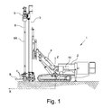
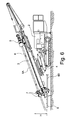
- the drilling or excavating machine suitable for all drilling technologies, rotary, rotary percussion, vibration, driving and mixing and injection, indicated in its entirety with the reference number 1, substantially consists of a machine body 2, mounted on tracks or wheels that allow it to move in the construction site, of a guide antenna or mast 3, on which the drilling means slide, and of a kinematic mechanism 4 that allows the guide antenna 3 to move relative to the machine body 2 to bring it from a closed configuration, used for transport, to a working configuration, in which the guide antenna 3 can be in a vertical, inclined or horizontal position.
- the machine 1 can be of the type for making piles, micropiles, tie rods, mechanical mixing or water wells.
- a drilling system can be mounted that uses percussion in addition to rotation and vibration in addition to rotation.
- the rotary head 5 can be mounted slidably in the transverse sense (in a direction perpendicular to the plane X-Z of the side view) both relative to the trolley that guides it, and relative to the guide antenna 3.
- the trolley In the longitudinal direction the trolley is integral with the rotary head 5, so in turn it is able to slide on the guide antenna 3 along a drill axis coinciding with the axis of the drill shafts 6A which, in the case of Figure 1 , coincides with the axis Z.
- a reference system is defined in which the ideal axis X is parallel to the longitudinal (forward-backward) direction of the machine 1, the axis Z indicates the vertical direction, or however perpendicular to the ground or floor on which the machine 1 lies, and the axis Y is parallel to the transverse direction (right flank-left flank) of the machine 1.
- the clamps 7 can comprise a pair of clamps 7 or, equivalently, a clamp 7 and an unscrewing device.
- the added shaft 6A is then connected to the drill stem 6 at a height above the clamps 7.
- both the drill shafts 6A are used (internally), and casing pipes (externally to the shafts) and these pipes may require the application of three clamps 7, at least one of which is an unscrewing device.
- the aforesaid operations must be carried out in reverse order to extract the drill stem 6, unloading the shafts 6A in sequence.
- the phases of loading and unloading the shafts 6A can require the intervention of an operator who correctly positions said shafts 6A and hence who must move in proximity to the drill axis. Operations to maintain, inspect and replace the tool can also require the operator to move into this area.
- the area in proximity to the guide antenna 3 and to the drill stem 6 is deemed dangerous, because the operator could come into contact with the rotating members of the machine 1 and consequently may become entangled in them and be dragged. Another danger can consist of the movement of the rotary head 5 along the guide antenna 3, which could hit or drag the operator.
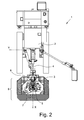
- the safety system of the present invention comprises a sensitive platform 9 provided with connecting and regulating means that allow said platform 9 to be associated with the machine 1 and, in particular, said platform 9 to be operatively connected to the guide antenna 3 to maintain it substantially parallel to the ground and raise it to a predefined height, preferably minimal, from the ground on which the machine 1 lies.
- the platform 9 is provided with a hole or a passage at the drill axis to allow the drill stem 6 to pass through the platform 9 itself.
- the platform 9 can be holed in such a way as to include the clamps 7 at least partially and to develop around them, allowing the clamps to pass through the platform 9 itself, at least in some working configurations.
- the platform 9 extends parallel to the horizontal plane X-Y to at least partially, but preferably completely, cover the dangerous area, defined as the entire area within which workers could come into contact with the rotating parts of the machine 1 used for drilling.
- the sensitive platform 9 will preferably have substantially circular or polygonal shape, with an approximate central area positioned on the axis of rotation of the drill stem 6.
- the platform 9 has such lateral development distance, relative to the axis of rotation, that a person positioned outside the platform 9 itself cannot reach the movable parts of the machine 1 involved in the drilling (in particular the drilling shafts 6A or the movable parts of the rotary heads 5), even extending an arm and/or leaning towards the drill axis. In this way, any person will be forced to step onto the platform 9 in order to access the drilling shaft 6A.
- the safety system of the present invention further comprises one or more sensitive devices 8 operatively connected with the platform 9, configured to detect the presence of one or more persons on the platform 9 and thus inside or in proximity to the dangerous area. In this condition the safety system sends an appropriate control signal to the machine 1.
- the sensitive devices 8 consist of pressure, force or displacement sensors, when one or more persons step onto the sensitive platform 9, by effect of their weight they cause the triggering or excitation of said sensitive devices 8, which in particular detect changes in the force acting on a reference point (detection or measurement point) or a pressure over a reference area (detection or measurement area).
- the sensitive devices 8 are calibrated in such a way that triggering only takes place when the weight detected on the platform 9 exceeds a predefined threshold value, compatible with the weight of a person (or of part of a person, e.g. in the order of tens of kilograms).
- the generated signal immediately controls all dangerous maneuvers to stop, in particular at least the rotation of the drill stem 6, in order to preserve the safety of the operators, and in some cases also the axial sliding of the rotary head 5 to stop, along with the other maneuvers preceding the drilling.
- the sensitive device 8 cannot be regulated directly on a trigger value, but it is arranged to simply send a signal proportional to the total weight of the platform 9 and of any load present on the platform 9.
- the signal is then managed by a control unit 10 that is programmable, generally fastened on the machine 1 and associated with its control systems in such a way as to be able to block dangerous maneuvers when the signal received exceeds a predefined threshold value, or when a combined event occurs.
- a combined event can coincide, for example, with a change in the weight of the platform 9 detected by first sensitive devices 8 and with the detection in height of a presence of a body, detected with second sensitive devices 8 for example of the optical, laser or the like.
- the two data are associated and the control unit 10 acts to protect any worker who stepped onto the platform 9.
- the sensitive devices 8 can measure at least one among the following quantities: force, displacement, elongation and pressure.
- the sensitive devices 8 can consist of loading cells, pressure switches, dynamometers or micro-switches able to directly or indirectly measure the load present on the sensitive platform 9.
- the control signal, generated consequently to the triggering of the sensitive device 8, can act directly on the actuators of the rotary head 5 in order to immediately stop at least the rotation of the drill stem 6 or, alternatively, to simultaneously block both the rotation of the shafts 6A, and the axial sliding of the rotary head 5 along the guide antenna 3.
- control signal generated by the triggering of the sensitive devices 8 can be sent to an electronic unit or programmable logic controller (PLC) 10 which, in addition to commanding at least the rotation of the drill stem 6 to stop, can manage a plurality of additional safety functions, such as the blocking of the sliding of the rotary head 5 and the emission of a sound or light signal that warns that the dangerous area has been breached.
- PLC programmable logic controller
- the sensitive devices 8 are transducers, e.g. loading cells, pressure switches or dynamometers able to generate proportional output signals
- a minimum threshold value of said signal corresponding to the effect of only the own weight of the platform 9, is set in the programmable logic controller 10.
- the presence of a person on the platform 9 will be detected on the basis of a change in the signal relative to this minimum threshold corresponding only to the own weight of the platform 9.
- the minimum threshold and the triggering threshold of the sensitive devices 8 can be set only by means of setting password-protected procedures, performed by authorized personnel.
- the sensitive devices 8 may detect, on the platform 9, weights lower than the triggering weight, but higher than the own weight of the platform 9 itself. Such weight increases can be caused, e.g., by the accumulation of debris or drill cuttings on the platform 9.
- a programmable logic controller 10 it is advantageous, especially in the presence of a programmable logic controller 10, also to impose a first warning threshold for the excessive accumulation of material on the platform 9.
- said warning threshold without blocking the machine 1, will warn the operator of the need to clear the accumulated debris from the platform 9.
- the warning threshold for an excessive accumulation of material will be set to a sufficiently low value. e.g. 5 or 10 kilograms, in any case far lower than the triggering threshold for the presence of a person on the platform 9.
- the safety system may, for example, activate appropriate light or sound signals.
- the accumulation of material may also be detected by sensors sensitive to the identification of objects or bodies, such as optical or laser sensors, or the like. Being mounted in series in height along the guide antenna 3, these sensors could determine which height the objects or debris reach. If the height is low, or however lower than the minimum height of a person, the system recognizes that these objects or debris are drill cuttings. In this case it may be sufficient to generate an accumulation warning. Vice versa, if the height exceeds a few tens of centimeters the system can associate this information with the fact that a human body is present on the platform 9 and hence signal its presence, sending this danger indication or intervening directly to block dangerous maneuvers.
- sensors sensitive to the identification of objects or bodies such as optical or laser sensors, or the like. Being mounted in series in height along the guide antenna 3, these sensors could determine which height the objects or debris reach. If the height is low, or however lower than the minimum height of a person, the system recognizes that these objects or debris are drill cuttings. In this case it may be sufficient to generate an accumulation warning. Vice versa,
- the stepping plane of the platform 9 is preferably constructed by means of grids, with suitably wide mesh and compatible with having foot-rest down on them, which allow any liquids or debris, projected from the drilling area, to flow through towards the ground.
- the deflectors will have a surface that is inclined and sloping towards the periphery or outside of the platform 9.
- the debris or the fluids, that are projected upwards and laterally during the drilling step, will tend to fall onto said deflectors and will be deviated in such a way that for the most part they will fall outside the platform 9 without accumulating thereon.
- the raised position of the platform 9 also makes it possible to easily clean the underlying area when an accumulation of material occurs in proximity to the drilled hole.
- Figures 3A, 3B and 4C show in detail a preferable solution of the safety system, comprising connecting and regulating means to make the sensitive platform 9 operatively connected or integral with the guide antenna 3.
- the kinematic mechanism 4 of the machine 1 makes it possible to incline the guide antenna 3 by an angle ⁇ relative to the vertical in the frontal or rear direction (rotating on the X-Z plane) to carry out inclined drillings.
- the first embodiment of the safety system shown in Figures 3A, 3B and 3C allows the platform 9 to be fastened to the guide antenna 3 to control at least a first relative rotation between the platform 9 and the guide antenna 3 through orientable connecting and regulating means, in such a way as to maintain the platform 9 substantially horizontal as the inclination of the guide antenna 3 changes.
- the platform 9 is orientable relative to the machine 1 and, in this case, relative to the guide antenna 3 to assume a desired access configuration.
- This configuration for the access of personnel can preferably be horizontal, or oriented parallel to the ground or to the bearing plane of the machine 1 (e.g.
- the safety system of the present invention thus enables the operator who has to enter and access the dangerous area, to add or remove shafts 6A or to carry out maintenance operations, to work walking on a plane that is substantially horizontal, or slightly inclined, or in steps (if the machine 1 bears on a highly steep slope) consisting of the sensitive platform 9, even when the guide antenna 3 is inclined frontally or backwards. In these configurations, with the guide antenna 3 inclined, the system continues to perform its safety function, remaining able to detect the presence of a person on the platform 9.
- Figure 3A shows the condition in which the guide antenna 3 is substantially vertical (parallel to the axis Z) and the platform 9 is substantially horizontal (parallel to the plane X-Y).
- the lower base of the guide antenna 3 is generally set down on the ground and it can be provided with a dedicated base plate.
- the platform 9 comprises connecting or regulating means so that it can be operatively connected or, in this specific case, made integral with the guide antenna 3 and positioned at a height that is slightly above the lower base of the guide antenna 3 itself. In this way, even the platform 9 is generally at a very low height relative to the ground (e.g. 20-30 cm, up to, for example, 70 cm) and, consequently, the operator can easily step onto and off the platform 9.
- the platform 9 comprises means for connection to the guide antenna 3 comprising a support framework 12 constrained to the base of the guide antenna 3.
- the connection between the platform 9 and the support framework 12 takes place through a first hinge or pivot 11 that has an axis of rotation perpendicular to the longitudinal axis of the guide antenna 3 and is oriented parallel to the axis Y when the guide antenna 3 lies on the plane Z-X, as shown in Figures 3A, 3B and 3C .
- the connection between the support framework 12 and the guide antenna 3 can be of the detachable type, by means of bolting, or of the fixed type, by means of welding.
- the platform 9 can be positioned approximately at the same height as the lower clamp 7 and, for this reason, it has a free central passage with such size and shape as to allow the clamp 7 to pass through the platform 9 (as shown also in Figure 2 ).
- the orientable connecting and regulating means of the platform 9 comprise a first linear actuator 13 and a linkage 14, both hinged to the support framework 12, through which the platform 9 is held in position.
- the linkage 14 acts on the platform 9 through a second hinge or pivot 15 that has an axis of rotation parallel to that of the first hinge 11.
- the own weight of the platform 9 and any loads present on the platform 9 generate two equal and opposite forces on the hinges 11 and 15.
- the sensitive devices 8 consist of loading cells, in the form of a pin provided with instruments, which are inserted indifferently either into the first hinge 11 for the rotation of the platform 9, or into the second hinge 15, or into both if one wants to have two values to be mutually compared.
- the loading cells 8 are able to measure the reaction force generated on the first hinge 11 and thus to evaluate the weight present on the platform 9.
- the sensitive devices 8 are triggered, generating the control signal.
- the regulating means of the platform comprise a first linear actuator 13 which consists of a hydraulic cylinder or jack, whilst a pressure sensor measures the pressure that keeps the platform 9 balanced.
- the pressure necessary to balance only the own weight of the platform 9 is taken as a reference to calibrate the system ("zero" condition). Every subsequent load change on the platform 9 is detected by the pressure sensor because it causes a change in the working pressure of the first actuator 13.
- the first actuator 13 can also be manual and adjustable, e.g. extending by means of female-screw, rack and pinion, crank mechanism, etc.
- Figure 3B shows an operating step in which the guide antenna 3 is inclined frontally by an angle ⁇ (in the positive direction) and the platform 9, which is connected to the guide antenna 3 by its own connecting and regulating means, is oriented in the substantially horizontal direction by appropriate operation of said connecting and regulating means, i.e. of the first actuator 13 and of the linkage 14.
- Figure 3C shows an operating step in which the guide antenna 3 is inclined backwards by an angle ⁇ (in the negative direction) and the platform 9 is oriented in the substantially horizontal direction by appropriate operation of the first actuator 13 and of the linkage 14.
- Figure 3D shows an operating step in which the guide antenna 3 is inclined frontally by an angle ⁇ by 90°, i.e. it is substantially horizontal, and also the platform 9 is oriented in substantially horizontal direction by appropriate operation of the first actuator 13 and of the linkage 14.
- the capability of reaching this mutual position between the guide antenna 3 and the platform 9 is advantageous when transporting the machine 1.
- the guide antenna 3 is positioned horizontal above the machine body 2 and by orienting the platform 9 in the horizontal position it is possible to keep the platform 9 mounted without increasing the height of the machine 1.
- a linkage 14 makes it possible to increase the inclinations achievable by the platform 9 and, thereby, to offset the inclinations of the guide antenna 3 even starting from a posterior inclination with negative angle ⁇ , e.g. 20°-30°, until reaching a front inclination with positive angle ⁇ of 90°, i.e. with the guide antenna 3 horizontal and positioned above the machine body 2. If the range of inclinations reachable by the guide antenna 3 is smaller, it is possible to use simpler connecting and regulating systems to actuate the platform 9, e.g. connecting the first actuator 13 directly to the platform 9 without the interposition of a linkage 14.
- the platform 9 is made temporarily integral with the guide antenna 3 with a fastening means (pin, screw, block, etc.) and the first actuator 13 can be detached and fastened in another point of the guide antenna 3, thus allowing further extension of the opening movement, as the following step.
- a fastening means pin, screw, block, etc.
- the actuation of the first actuator 13 for regulating and inclining the platform 9 can be managed independently by the operator or it can preferably be automated to maintain the platform 9 positioned horizontally.
- additional control sensors will have to be installed, e.g. inclinometers able to sense the orientation of the platform 9 and to send a signal to the control unit 10, which will accordingly control the movement of the first actuator 13 in order to appropriately incline the platform 9.
- the possibility of inclining the platform 9 relative to the guide antenna 3 can be advantageously used when cleaning the drilling area. Maintaining the guide antenna 3 substantially vertical, it is possible, for example, to incline the platform 9 upwards, moving it yet farther away from the ground. In this way, it will be easier to access the area in proximity to the mouth of the borehole in the ground to remove, using a cleaning tool, the debris accumulated under the platform 9.
- the kinematic mechanism 4 of the drilling machines is very simple and it has only one hinge oriented with axis Y.
- the guide antenna 3 is very close to the framework of the machine 1. Consequently, for these machines the platform 9 associated with the machine 1 could comprise connecting and regulating means to be constrained to the guide antenna 3 rotatably around the axis Y and the rotation of the platform 9 would be limited by a mechanical fastening means appropriately positioned on the (fixed) framework of the machine 1, in such a way that the platform 9 itself is always horizontal or has a desired orientation.
- the platform 9 could comprise connecting and regulating means to be constrained directly to the framework of the machine 1, at a predefined height raised from the ground, and in this case the platform 9 itself could be advantageously fixed or orientable only with small angles (e.g. to make up for any inclinations of the ground or reference plane).
- the platform 9 can comprise regulating means consisting of rotary actuators 13, e.g. mounted directly on the axis of the first hinge 11 or meshing with gears fixed on the axis of the first hinge 11.
- the sensitive devices 8 could consist of pressure switches or of pressure transducers able to measure the pressure of the rotary actuator 13 that is induced by the load present on the platform 9.
- the platform 9 could be hinged to the guide antenna 3 through the first hinge 11 and comprise regulating means such as flexible elements or telescopic elements that connect the platform 9 to the guide antenna 3 (drawbridge configuration) to regulate the inclination of the platform 9 itself.
- regulating means such as flexible elements or telescopic elements that connect the platform 9 to the guide antenna 3 (drawbridge configuration) to regulate the inclination of the platform 9 itself.
- the sensitive devices 8 could consist of loading cells or dynamometers fastened to an extremity of the flexible or telescopic elements, in order to measure the pull induced on these elements by the load present on the platform 9.
- the platform 9 can be rotated manually around the first hinge 11, while the second hinge 15 of the platform 9 slides within a slot obtained on the support framework 12 or on the guide antenna 3. In this way it is successively possible to block the second hinge 15 with friction mechanical stops when the platform 9 has reached the horizontal orientation.
- the safety system of the invention advantageously provides for the possibility of offsetting these inclinations as well, maintaining the platform 9 substantially horizontal.
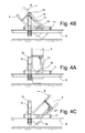
- Figures 4A, 4B e 4C are rear views of the guide antenna 3, i.e. they are obtained observing the guide antenna 3 from the kinematic mechanism 4 towards the drill stem 6. For greater clarity, the clamps 7 fastened at the base of the guide antenna 3 have also been hidden.
- the safety system of the present invention enables the operator who has to enter into the dangerous area, to add or remove shafts 6A or to carry out maintenance operations, to work walking on a substantially horizontal plane, consisting of the sensitive platform 9, even when the guide antenna 3 is inclined laterally by an angle ⁇ to the right or to the left. In particular, in these configurations the system continues to perform its safety function, still being able to detect the presence of a person on the platform 9.
- FIG 4A shows the condition in which the guide antenna 3 is substantially vertical and the platform 9 is substantially horizontal.
- the platform 9 still comprises connecting means such as the support framework 12, hinged to the platform 9 by means of a first hinge 11 that enables the frontal inclinations of the platform 9, as previously mentioned with reference to Figures 3A, 3B and 3C .
- the support framework 12 in turn is hinged to the guide antenna 3 by orientable connecting means such as a hinge or pin 16 that allows the lateral inclinations of the support framework 12 and of the platform 9 relative to the guide antenna 3.
- This hinge 16 has an axis of rotation perpendicular to the axis of the first hinge 11 and both the hinges 11 and 16 belong to the support framework 12, and thus to the platform 9, whereby maintaining a constant mutual position.
- the lateral inclination of the platform 9 is imposed and maintained by the orientable connecting and regulating means with which it is provided, e.g. an additional actuator 17 of the linear type that can have an extremity hinged to the guide antenna 3 and the other extremity hinged to the support framework 12.
- the activation of the actuator 17 causes the rotation of the support framework 12 and, consequently, of the platform 9 relative to the guide antenna 3.
- Figure 4B shows the condition in which the guide antenna 3 is inclined relative to the vertical by a positive angle ⁇ to perform rightward inclined drillings and the platform 9 is maintained substantially horizontal.
- Figure 4C shows the condition in which the guide antenna 3 is inclined relative to the vertical by a negative angle ⁇ to perform leftward inclined drillings and the platform 9 is maintained substantially horizontal.
- the actuation of the cylinder 17 for the lateral inclination of the platform 9 can be managed independently by the operator or it can preferably be automated to maintain the platform 9 horizontal.
- control sensors will have to be installed, e.g. inclinometers, able to sense the orientation of the platform 9 and to send a signal to the control unit 10, which will accordingly control the movement of the actuator 17 in order to appropriately incline the platform 9.
- the lateral rotation of the platform 9 relative to the hinge 16 and to the guide antenna 3 can be controlled by one or more rotary actuators 17, e.g. mounted on the axis of the hinge 16 or meshing with such hinge 16.
- the sensitive devices 8 could consist of pressure switches able to measure the pressure of the rotary actuator 17 that is induced by the load present on the platform 9.
- FIG. 5A shows a possible shape of the platform 9, provided with a sufficiently wide central passage to allow all inclinations of the clamps 7 without interference.
- Figure 5A shows a top view of the platform 9 integral with the guide antenna 3, which in the specific case is in the vertical position.
- the platform 9 will move integrally with the guide antenna.
- the platform 9 can fully extend around the drilling area, as shown in Figure 2 .
- the platform 9 can also be monolithic and have lateral size that is preferably no greater than that of the drilling machine 1, so that it can remain mounted on the machine 1 even during transport.
- the sizes of the platform 9 could limit the operating capabilities or the movements of the machine 1.
- the platform 9 can comprise at least one load-bearing central element 9A, which always remains constrained to the guide antenna 3 directly or through a support framework 12.
- the load-bearing central element 9A has sufficient minimum dimensions to extend laterally relative to the clamps 7 and reach at least the front edge of the clamps 7.
- To this load-bearing central element 9A can be connected one or more lateral platform elements 9C and one or more frontal platform elements 9B, movable and/or removable with respect to the load-bearing central element 9A.
- the connection can be of the hinge type, so that the frontal and lateral elements 9B and 9C can be overturned or rotated by 90° relative to the load-bearing central element 9A, assuming a vertical position to reduce their frontal or lateral size.
- the connection can be press-fit or bolted.
- the frontal element 9B of the platform 9 can be disassembled to allow the drill stem 6 to approach the wall as closely as possible.
- the frontal element 9B can be rotated by 90° around the hinges oriented with the axis of rotation parallel to the axis Y in Figure 5A , which connect it to the load-bearing central element 9A, and it can be positioned vertically to reduce its frontal size. In these conditions the area in front of the guide antenna 3 and of the drill stem 6 will not be accessible to the operators, because of the presence of a wall.
- the only possible access route to the dangerous area will be the route coming from the lateral areas relative to the guide antenna 3.
- the presence of a person is detected by the lateral platforms 9C, which trigger the sensitive devices 8, installed in such a number as to cover all the different modular compositions which the platform 9 can assume.
- the safety system ensures that the presence of a person in the dangerous area will be detected.
- the measurement of the sensor 8 that detects weight and/or pressure and/or displacement will become the new reference value on which the safety system will evaluate changes (increases in the measurement correspond to greater weight on the platform 9, hence to the start of danger due to the presence of a worker on the platform 9).
- the lateral element 9C of the platform 9 can be disassembled to make it possible to approach the wall with the drill stem 6 as closely as possible.
- the lateral element 9C can be rotated by 90° around the hinges that connect it to the load-bearing central element 9A and positioned vertically to reduce its lateral size. In these conditions the area on a side of the guide antenna 3 and of the drill stem 6 will be inaccessible by the operators, because of the presence of a wall. In the remaining possible access areas, i.e.
- the lateral platform 9C On the side opposite the wall and in the area in front of the guide antenna 3, the presence of a person is detected by the lateral platform 9C, or by the frontal platform 9B, which trigger the sensitive devices 8.
- the lateral platform 9C and frontal platform 9B When folded, the lateral platform 9C and frontal platform 9B also serve as guards and railings.
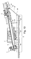
- Figure 6 shows the drilling machine 1 working with large frontal inclinations relative to the vertical, i.e. with high ⁇ angles and the guide antenna 3 that tends to be positioned nearly horizontally and at low height. Under these operative conditions, it occurs that a long segment of the drill stem 6 is at a lower height than a height H that defines the height limit of the dangerous area. Said height H defines the height, relative to the ground, up to which it is necessary to avoid a possible contact between a person and the drilling members. The height H, which can reach up to 2.5 meters, is thus the height up to which a person with his feet on the ground risks dangerous contacts with the moving drilling members.
- the movable parts of the machine 1 involved in the drilling steps but located at a height above the height H do not need protections.
- the sensitive platform 9 To prevent operators from coming in contact with the rotating parts up to the height H, the sensitive platform 9 must extend throughout the length of the vertical projection of the segment of shafts 6A for which the operator, after stepping onto the platform 9, is below the height H. Hence, the protection height from the ground is given by the height H plus the height of the platform 9 from the ground.
- the platform 9 can be further expanded by adding other additional platform elements 9D (also visible in Figure 5B ) which are integrally fastened to the platform 9 and extend towards the machine body 2, or posteriorly to the guide antenna.
- additional platform elements 9D also visible in Figure 5B
- the operator will have to step onto one of the elements 9A, 9B, 9C and/or 9D of the platform 9 and, in this case, the sensitive devices 8 will be triggered with the consequent transmission of the stop signal.
- the operator steps onto the additional platform element 9D his weight will tend to cause the platform 9 to rotate relative to the first hinge 11, generating two reactions on the hinges 11 and 15.
- the reaction on the first hinge 11 is detected by a sensor 8 sensitive to the change in force and/or weight and/or displacement, in particular for example a loading cell as already explained in relation to Figure 3A .
- the additional platform element 9D could have appropriately shaped attachment points so that, once it is fastened to the platform 9, the additional platform element 9D has a raised stepping plane relative to the load-bearing central element 9A.
- the platform can be constructed in steps and, in the track area, it can be positioned superiorly relative to the track itself.
- Figure 7A shows the drilling machine 1 in an operative configuration for making horizontal tie rods with transverse or lateral drilling, and drilling means positioned in overhang frontally (sideways) relative to the guide antenna 3.
- the guide antenna 3 is rotated by an angle ⁇ equal to 90° relative to the vertical plane X-Z.
- This operative configuration is generally used to drill holes in a substantially vertical wall, placing the base of the guide antenna 3 close to or against that wall.
- the entire area to the left of the clamps 7 is not reachable by a person, due to the presence of the wall that is being drilled. In this case, the entire drill stem 6 and the rotary head 5 as well are positioned below the height H and hence they are entirely included within the dangerous area.
- the drill stem 6 and the rotary head 5 would be reachable by a person positioned in front of the guide antenna 3, or from the side opposite the machine body 2 relative to the guide antenna 3. They would not be reachable, instead, by a person positioned behind the guide antenna 3, or at the same side of the machine body 2 relative to the guide antenna 3. From this latter position, the drill stem 6 and the rotary head 5 would be shielded by the height and depth size of the guide antenna 3.
- the platform 9 To prevent a person from coming into contact with rotating or moving members involved in the drilling steps, the platform 9 must extend in overhang frontally to the guide antenna 3 for the entire segment that goes from the base of the guide antenna 3 to the rotary head 5.
- Figure 7B is a side view, i.e. a view on the plane Z-X, of the safety system applied to the machine 1 in the same condition as in Figure 7A .
- the platform 9 must extend in the frontal direction to the guide antenna 3, i.e. along the axis X, by a distance sufficient to prevent a person whose feet are on the ground from reaching the moving drilling means without stepping onto the platform 9. It is also possible to extend the length of the platform 9 in the direction Y, so that it continues in overhang relative to the clamps 7 and to the base of the guide antenna 3.
- a platform 9 constructed according to a second embodiment.
- the platform 9 is still operatively connected to the guide antenna 3 and it is provided with connecting and regulating means to be able to be maintained suspended in two points or about two axes, defined by respective hinges 19 and 22, situated at the opposite ends of the platform 9.
- a first extremity of the platform 9 is connected in proximity to the base of the guide antenna 3 by a connecting means consisting of a first hinge 19.
- the first hinge 19 has an axis of rotation that is transverse relative to the longitudinal axis of the guide antenna 3 and, in particular in the configuration of Figure 7 , it is oriented along the axis X.
- the first hinge 19 can be positioned on an arm 18 of the platform 9 that is connected to the guide antenna 3 or to a clamp 7.
- the second extremity of the platform 9 comprises other connecting and regulating means such as a second hinge 22 that will be at a sufficient distance from the base of the guide antenna 3 to cover the entire dangerous area.
- the second hinge 22 of the platform 9 is provided on an additional connection element 20 or tie rod with variable length, belonging to the platform 9 and in turn connected to the guide antenna 3 by a third hinge 21, preferably positioned in the upper segment of the guide antenna 3 and having an axis of rotation parallel to that of the first hinge 19.
- the third hinge 21 can advantageously be located on the rear surface of the guide antenna 3, i.e.
- the connecting and regulating element 20 with variable length can preferably consist of a telescopic arm able to extend and contract, as well as to change its own inclination relative to the guide antenna 3, in order to adapt to the different possible inclinations of the guide antenna 3 and to the different possible lengths of the platform 9. In this way, rotating the adjustable connection element 20 about the axis of the third hinge 21 and adjusting its length, it is possible to maintain the platform 9 positioned horizontally.
- the platform 9, in this second embodiment of the safety system can be composed by mutually connecting and fastening a plurality of additional platform elements 9D arranged side by side to each other, until reaching the necessary length on the basis of the inclination of the guide antenna 3.
- the safety system also comprises sensitive devices 8 able to detect the presence of a person on the platform 9 and, in this case, able to send a control signal to stop at least the rotation of the drill stem 6.
- the weight of a person located on the platform 9 generates vertical reactions on the hinges 19 and 22 of the platform 9 and on the hinge 21 of the adjustable connection element 20 and also generates a traction force on said connection element 20.
- a winder device or winch 23 is mounted from which unwind connecting and regulating means of the platform 9 consisting of two tensioned ropes 25 and 26, mutually parallel and connected to the first hinge 19 positioned in proximity to the base of the guide antenna 3.
- the two ropes 25 and 26 can be tensioned by the rotation of the winch 23, or by the extension of the adjustable tie rod 20.
- the presence of a person on the platform 9 causes the variation of the tension of the ropes 25 and 26, which can be detected by the sensitive devices 8, e.g. dynamometers, interposed between the first hinge 19 and the lug of the ropes 25 and 26, or loading cells inserted in the hinges 19 and/or 22.
- the traction of the cables 25 and 26 also generates a torque on the winch 23 which tends to make it rotate on the axis of the second hinge 22.
- sensitive devices 8 pressure switches
- the ropes 25 and 26 can be adjusted to cause the platform 9 to assume an inclined configuration, or they can be slackened until the platform 9 itself bears on the ground.
- the necessary length of the platform 9 to extend throughout the dangerous area changes. Therefore, as the inclination ⁇ changes, the length of the platform 9 can be adapted by adding or subtracting modular elements 9E to the platform 9. It is also necessary to change the length and the orientation of the tie rod 20 with variable length. If the tie rod 20 is embodied by a telescopic element, its length can be changed by means of a dedicated linear actuator, or a linear actuator can be used directly to embody the tie rod 20. By means of a second actuator 24, connected to the guide antenna 3 and to the tie rod 24, it is also possible to orient the tie rod 20 making it rotate about the third hinge 21.
- the platform 9, being able to rotate in the two points of suspension defined by the hinges 19 and 22, is always maintained raised relative to the ground and oriented along a substantially horizontal plane even when the guide antenna 3 is inclined according to an angle ⁇ .
- the actuation of the actuators that regulate the length and the inclination of the tie rod 20 can be managed independently by the operator, or it can preferably be automated to maintain the platform 9 horizontal.
- additional sensors 8 will have to be installed, e.g. inclinometers able to sense the orientation of the platform 9 and to send a signal to the control unit 10, which will accordingly control the movement of the actuators.
- connection element 20 with variable length can consist of an adjustable tie rod, by a chain or by another flexible element.
- the connection element 20 with variable length can consist of an adjustable tie rod, by a chain or by another flexible element.
- the most appropriate hinging point 21 can be used, i.e. generally the closest one to the vertical line passing through the second hinge 22.
- the arm 18 and the tie rod 20 can be fastened and oriented in mirror-like manner relative to the longitudinal centerline plane of the guide antenna 3. This makes it possible to install the safety system, comprising the platform 9, even when the guide antenna 3 is rotated laterally by an angle ⁇ in the opposite direction to the one described with reference to Figure 8 .
- the drilling machine 1 is in an operative configuration for the execution of horizontal tie rods with transverse or lateral drilling, and drilling means positioned over the guide antenna 3.
- the guide antenna 3 is rotated by a 90° angle relative to the vertical plane X-Z.
- This operative configuration is generally used to drill holes in a substantially vertical wall, placing the base of the guide antenna 3 close to or against that wall.
- the entire area to the left of the clamps 7 is not reachable by a person, due to the presence of the wall that is being drilled. In this case, the entire drill stem 6 and the rotary head 5 as well are positioned below the height H and hence they are entirely included within the dangerous area.
- the platform 9 Because of the presence of the tracks that would interfere with a single platform 9, which extends throughout the length of the guide antenna 3, it is advantageous for the platform 9 to be constructed in two distinct segments at the side of the machine body 2. Each segment of the platform 9 is still integral with the guide antenna 3 and it is maintained suspended in two points or about two axes situated at the opposite extremities of the segment itself.
- the load-bearing central element 9A is hinged to the guide antenna 3 by a first hinge 11 and it can preferably be oriented by a linkage 14 and a first actuator 13.
- To the load-bearing central element 9A can be connected one or more modular lateral platform elements 9G, positioned on one side towards the machine body 2 so that these lateral platform elements 9G extend throughout the dangerous area until reaching in proximity to the track.
- the number and the length of the lateral platform elements 9G can be changed according to the configuration of the guide antenna 3.
- the load-bearing central element 9A can be connected one or more modular lateral platform elements 9H, positioned on the side opposite the machine body 2 so that these lateral platform elements 9H extend throughout the dangerous area until reaching in proximity to the rotary head 5.
- the extremity of this segment that is far from the base of the guide antenna 3 is maintained suspended by at least one tie rod 27 with variable length.
- the adjustable tie rod 27 is constrained to a first hinge 28 on the platform 9 and to a second hinge or axis 29 on the guide antenna 3.
- the adjustable tie rod 27 can consist of one or more ropes gathered and tensioned by a winder device or winch 30 arranged with the axis of rotation matching the second hinge 29.
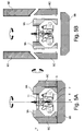
- FIG. 9B On the side of the guide antenna 3 oriented towards the machine body 2, in the section between the size of the machine body 2 and the position of the rotary head 5, are positioned additional modular elements of the platform 9, indicated with the reference 9F in Figure 9B , that are integral with the guide antenna 3 and extend over the dangerous area.
- the number and the length of the modular platform elements 9F can be changed according to the configuration of the guide antenna 3.
- the extremity of the modular platform elements 9F that is far from the base of the guide antenna 3 is maintained suspended by at least one tie rod 31 with variable length.
- the adjustable tie rod 31 is constrained to a first hinge 32 on the platform element 9F and to a second hinge or axis 33 on the guide antenna 3.
- the adjustable tie rod 31 can consist of one or more ropes gathered and tensioned by a winder device or winch 37 arranged with the axis of rotation matching the second hinge 33.
- the extremity of the platform elements 9F that is closer to the base of the guide antenna is maintained suspended by at least one tie rod 34 with variable length, constrained to the guide antenna 3 in a hinging point 35.
- the extremity of the platform elements 9F that is closer to the base of the guide antenna 3 can be maintained suspended also by a support element 36 connected to the lateral platform elements 9H positioned on the opposite side of the guide antenna 3.
- the inner part of the platform elements 9H and 9F, i.e. the one oriented towards the guide antenna 3, could be protected by a railing.
- the presence of a person on one of the modular platform elements 9A, 9F, 9G and 9H of the platform 9 can be detected by a plurality of sensitive devices 8, which are triggered by the effect of the weight of the person on the platform 9 and generate a control signal.
- These sensitive devices 8 can consist, for example, of loading cells or of pins provided with instruments applied in the hinges 11, 28, 29, 32 and 33. Equivalently, the sensitive devices 8 could consist of dynamometers or of other pull sensors applied to the adjustable tie rods 27, 31 and 34.
- Figure 10 shows an operative condition of the machine 1 obtained starting from the condition of Figure 9A and rotating the guide antenna 3 on the plane Y-Z.
- the length of the platform 9 can be adapted by adding or subtracting modular platform elements 9H and 9F, to protect the entire dangerous area.
- the length of the tie rods 27, 31 and 34 it is possible to maintain the modular platform elements 9H and 9F substantially horizontal and raised relative to the ground, maintaining the safety function of the system.
- the length of the adjustable tie rods 27, 31 and 34 could be automated, controlling linear actuators or winches and commanding them according to the inclinations detected by inclinometers installed on the platform 9. In this way it is possible to maintain the platform 9 horizontal as the inclination of the guide antenna 3 changes relative to the ground.
- the safety system it is also possible to use sensitive mats or sensitive strips to place and fix onto the stepping plane of the platform 9.
- These mats or strips contain within them, buried in their thickness, sensitive devices 8 able to detect the presence of a person on the platform 9 through the pressure exerted by the person on the mats or on the strips.
- the sensitive devices 8 can consist, for example, of normally open contacts that are closed by the weight of a person when he treads on the strip and, in this condition, they trigger the transmission of a control signal to the machine 1 to stop rotation. Once pressure is no longer applied on the strip or on the mat, the sensitive device 8 returns to the untriggered initial condition.
- the sensitive devices 8 can consist, for example, of normally closed contacts that are opened by the weight of a person when he treads on the strip and, in this condition, they trigger the transmission of a control signal to the machine 1 to stop rotation.
- the sensitive devices 8 buried in the mats or in the strips can consist of strain gauges that detect the deformation of the mat or of the strip when they are treaded on and, in this condition, they are triggered, sending the control signal to the machine 1 to stop rotation.
- the sensitive mats or strips will advantageously be arranged on a platform 9 that has a gridded or holed stepping surface, obtaining mutually spaced apart strips on the platform 9 in order to leave spaces between adjacent strips that allow debris to traverse the gridded surface and fall under the platform 9 without accumulating thereon.
- the spacing between the strips must be sufficiently small to prevent a person from climbing onto the platform 9 stepping on the aforesaid spaces without triggering the sensitive devices 8.
- the platform 9 whilst remaining operatively connected to the machine 1, can be maintained at zero height relative to the ground on which the drilling machine 1 bears or, in other words, it can bear directly on the ground.
- the safety system fully maintains its functionalities, because these types of sensitive devices 8 do not require a displacement of the platform 9 in the vertical direction to be triggered.
- the platform 9 could be able to slide relative to the guide antenna 3 in the longitudinal direction of the guide antenna 3. In this way, maintaining the base of the guide antenna 3 bearing on the ground, it will be possible to regulate the height of the platform 9 relative to the ground.
- This capability facilitates the operations for cleaning and removing debris from underneath the platform 9 and it can also prevent interference between the platform 9 and the ground, e.g. when it is necessary to carry out vertical drillings on an inclined ground.
- This solution is obtainable for example by means of a support framework 12 constructed in two slidable parts instead of with a single monolithic body. A first part of the framework 12 would remain hinged to the guide antenna 3 through the hinge 16, whilst the second part of the framework 12 could translate relative to the first part, by means of an appropriate actuator, moving the platform 9 along the guide antenna 3.
- One of the types of machine 1 to which the safety system of the present invention can be applied is an excavating machine for performing water wells.
- the machine body 2 can consist of a self-propelled truck or of a semi-trailer fitted with wheels.
- This solution considerably increases the speed of motion of the machine 1 and is advantageous when performing short-duration drilling operations at mutually distant sites.
- the guide antenna 3, substantially identical to the one used in the embodiments already described, in this case can be connected to the framework of the truck or of the semi-trailer through a hinge or kinematic mechanism 4 in such a way as to be able to shift from a reclined position for transport to a substantially vertical position for work.
- the drilling operations are substantially vertical and generally only small inclinations of the guide antenna 3 are required to offset the inclination of the ground on which the machine body 2 bears. Consequently, in these cases the kinematic mechanism can be highly simplified.
- a double head is used and drilling is accomplished advancing into the ground both with the drill shafts 6A (internally), and with casing pipes (externally to the shafts) which are then left in the borehole to constitute the walls of the well.
- the platform 9 associated with the drilling machine 1 is present.
- the platform 9 can be operatively connected to the guide antenna 3 or to the machine body 2.
- the platform 9 extends parallel to the horizontal plane X-Y and it is maintained raised from the ground at a minimum height to at least partially, but preferably completely cover the dangerous area.
- the platform 9 comprises orientable connecting and regulating means, e.g. a linear actuator, which enables to regulate the inclination of the platform 9 relative to the machine body 2 or to the guide antenna 3 to keep the platform 9 stationary in the operative position.
- the safety system of the present invention further comprises one or more sensitive devices 8 operatively connected with the platform 9, configured to detect the presence of one or more persons on the platform 9 and thus inside or in proximity to the dangerous area.
- the sensitive devices 8 are of the same types already described for the previous embodiments of the safety system and can be installed in the same ways. If the presence of a person is detected, the safety system acts in the ways already described, interrupting at least the rotation of the shafts and possibly also the translation of the rotary head.
Landscapes
- Engineering & Computer Science (AREA)
- Life Sciences & Earth Sciences (AREA)
- Geology (AREA)
- Mining & Mineral Resources (AREA)
- General Engineering & Computer Science (AREA)
- Physics & Mathematics (AREA)
- Environmental & Geological Engineering (AREA)
- Fluid Mechanics (AREA)
- General Life Sciences & Earth Sciences (AREA)
- Geochemistry & Mineralogy (AREA)
- Mechanical Engineering (AREA)
- Earth Drilling (AREA)
Applications Claiming Priority (1)
| Application Number | Priority Date | Filing Date | Title |
|---|---|---|---|
| ITMI20141442 | 2014-08-06 |
Publications (2)
| Publication Number | Publication Date |
|---|---|
| EP2982829A1 true EP2982829A1 (de) | 2016-02-10 |
| EP2982829B1 EP2982829B1 (de) | 2017-06-28 |
Family
ID=51703256
Family Applications (1)
| Application Number | Title | Priority Date | Filing Date |
|---|---|---|---|
| EP15179406.2A Active EP2982829B1 (de) | 2014-08-06 | 2015-07-31 | Sicherheitssystem zur kontrolle eines gefahrenbereichs einer bohrmaschine |
Country Status (1)
| Country | Link |
|---|---|
| EP (1) | EP2982829B1 (de) |
Cited By (2)
| Publication number | Priority date | Publication date | Assignee | Title |
|---|---|---|---|---|
| WO2019125643A1 (en) * | 2017-12-19 | 2019-06-27 | Caterpillar Global Mining Equipment Llc | Platform based drill capable of negative angle drilling |
| IT202000025255A1 (it) * | 2020-10-26 | 2022-04-26 | Soilmec Spa | Macchina da fondazioni e metodo per il controllo di tale macchina |
Citations (3)
| Publication number | Priority date | Publication date | Assignee | Title |
|---|---|---|---|---|
| FR2885401A1 (fr) * | 2005-05-09 | 2006-11-10 | Cie Du Sol Soc Civ Ile | Systeme de securite pour foreuse |
| US20100237714A1 (en) * | 2009-03-20 | 2010-09-23 | Soilmec S.P.A. | Safety device for emergency interruption of drilling maneuvers (as amended) |
| GB2479749A (en) * | 2010-04-20 | 2011-10-26 | Cementation Skanska Ltd | Drill rig optical safety system |
-
2015
- 2015-07-31 EP EP15179406.2A patent/EP2982829B1/de active Active
Patent Citations (3)
| Publication number | Priority date | Publication date | Assignee | Title |
|---|---|---|---|---|
| FR2885401A1 (fr) * | 2005-05-09 | 2006-11-10 | Cie Du Sol Soc Civ Ile | Systeme de securite pour foreuse |
| US20100237714A1 (en) * | 2009-03-20 | 2010-09-23 | Soilmec S.P.A. | Safety device for emergency interruption of drilling maneuvers (as amended) |
| GB2479749A (en) * | 2010-04-20 | 2011-10-26 | Cementation Skanska Ltd | Drill rig optical safety system |
Cited By (4)
| Publication number | Priority date | Publication date | Assignee | Title |
|---|---|---|---|---|
| WO2019125643A1 (en) * | 2017-12-19 | 2019-06-27 | Caterpillar Global Mining Equipment Llc | Platform based drill capable of negative angle drilling |
| US10633930B2 (en) | 2017-12-19 | 2020-04-28 | Caterpillar Global Mining Equipment Llc | Platform based drill capable of negative angle drilling |
| IT202000025255A1 (it) * | 2020-10-26 | 2022-04-26 | Soilmec Spa | Macchina da fondazioni e metodo per il controllo di tale macchina |
| WO2022090886A1 (en) * | 2020-10-26 | 2022-05-05 | Soilmec Spa | Foundation construction machine and method for controlling such machine |
Also Published As
| Publication number | Publication date |
|---|---|
| EP2982829B1 (de) | 2017-06-28 |
Similar Documents
| Publication | Publication Date | Title |
|---|---|---|
| NL2009942C2 (en) | A safety device for an aerial lift, a method of operation thereof, an aerial lift having the safety device, a kit of parts and a method of installation thereof for providing the safety device in an aerial lift. | |
| AU2016367175B2 (en) | Powered ladder for large industrial vehicles | |
| EP3424869B1 (de) | System zur stabilisierung von selbstangetriebenen arbeitsmaschinen | |
| EP3255239B1 (de) | Baumaschine mit rechnereinheit zum ermitteln eines verstellbereichs | |
| JP5828831B2 (ja) | 接近用装置 | |
| US8651236B2 (en) | Operator cage | |
| AU2012204037B2 (en) | Machine access device | |
| US20180162708A1 (en) | Anti-pothole aerial work platform | |
| US8567312B2 (en) | Bulk bag conditioning system | |
| EP3672900A1 (de) | Bauelementhebeverstärker | |
| CN116255151B (zh) | 一种竖井钻挖一体式施工平台装置及方法 | |
| DE60201190T2 (de) | Schlaglöcher schutzmechanismus | |
| EP2982829B1 (de) | Sicherheitssystem zur kontrolle eines gefahrenbereichs einer bohrmaschine | |
| DE602004007561T2 (de) | Hubarbeitsbühne mit Scherenmechanismus und Verfahren zur Kontrolle des Hebe-und Absenkungvorganges | |
| CA2618183A1 (en) | Liftable scaffold | |
| JP7166308B2 (ja) | 深礎掘削機 | |
| KR20100048537A (ko) | 수직이송 기능이 구비된 농업용 붐식 고소작업차량 | |
| DE3148119A1 (de) | Hebeanordnung | |
| EP2598819A1 (de) | Arbeitsbühne und deren verwendung | |
| JP4713038B2 (ja) | 削岩装置用ブーム装置 | |
| DE102015222485A1 (de) | Verfahren zur Hubhöhen- und/oder Schwenkwinkelbegrenzung eines Baggers | |
| JP4625686B2 (ja) | 作業車の安全制御装置 | |
| JP2018111922A (ja) | 掘削機 | |
| CN113845069B (zh) | 用于操作机械的提升系统 | |
| Kalairassan et al. | Analysis of load monitoring system in hydraulic mobile cranes |
Legal Events
| Date | Code | Title | Description |
|---|---|---|---|
| PUAI | Public reference made under article 153(3) epc to a published international application that has entered the european phase |
Free format text: ORIGINAL CODE: 0009012 |
|
| AK | Designated contracting states |
Kind code of ref document: A1 Designated state(s): AL AT BE BG CH CY CZ DE DK EE ES FI FR GB GR HR HU IE IS IT LI LT LU LV MC MK MT NL NO PL PT RO RS SE SI SK SM TR |
|
| AX | Request for extension of the european patent |
Extension state: BA ME |
|
| 17P | Request for examination filed |
Effective date: 20160727 |
|
| RBV | Designated contracting states (corrected) |
Designated state(s): AL AT BE BG CH CY CZ DE DK EE ES FI FR GB GR HR HU IE IS IT LI LT LU LV MC MK MT NL NO PL PT RO RS SE SI SK SM TR |
|
| GRAP | Despatch of communication of intention to grant a patent |
Free format text: ORIGINAL CODE: EPIDOSNIGR1 |
|
| STAA | Information on the status of an ep patent application or granted ep patent |
Free format text: STATUS: GRANT OF PATENT IS INTENDED |
|
| INTG | Intention to grant announced |
Effective date: 20170116 |
|
| GRAS | Grant fee paid |
Free format text: ORIGINAL CODE: EPIDOSNIGR3 |
|
| GRAA | (expected) grant |
Free format text: ORIGINAL CODE: 0009210 |
|
| STAA | Information on the status of an ep patent application or granted ep patent |
Free format text: STATUS: THE PATENT HAS BEEN GRANTED |
|
| AK | Designated contracting states |
Kind code of ref document: B1 Designated state(s): AL AT BE BG CH CY CZ DE DK EE ES FI FR GB GR HR HU IE IS IT LI LT LU LV MC MK MT NL NO PL PT RO RS SE SI SK SM TR |
|
| REG | Reference to a national code |
Ref country code: GB Ref legal event code: FG4D |
|
| REG | Reference to a national code |
Ref country code: CH Ref legal event code: EP |
|
| REG | Reference to a national code |
Ref country code: AT Ref legal event code: REF Ref document number: 905009 Country of ref document: AT Kind code of ref document: T Effective date: 20170715 |
|
| REG | Reference to a national code |
Ref country code: IE Ref legal event code: FG4D |
|
| REG | Reference to a national code |
Ref country code: DE Ref legal event code: R096 Ref document number: 602015003301 Country of ref document: DE |
|
| REG | Reference to a national code |
Ref country code: FR Ref legal event code: PLFP Year of fee payment: 3 |
|
| PG25 | Lapsed in a contracting state [announced via postgrant information from national office to epo] |
Ref country code: HR Free format text: LAPSE BECAUSE OF FAILURE TO SUBMIT A TRANSLATION OF THE DESCRIPTION OR TO PAY THE FEE WITHIN THE PRESCRIBED TIME-LIMIT Effective date: 20170628 Ref country code: GR Free format text: LAPSE BECAUSE OF FAILURE TO SUBMIT A TRANSLATION OF THE DESCRIPTION OR TO PAY THE FEE WITHIN THE PRESCRIBED TIME-LIMIT Effective date: 20170929 Ref country code: LT Free format text: LAPSE BECAUSE OF FAILURE TO SUBMIT A TRANSLATION OF THE DESCRIPTION OR TO PAY THE FEE WITHIN THE PRESCRIBED TIME-LIMIT Effective date: 20170628 Ref country code: NO Free format text: LAPSE BECAUSE OF FAILURE TO SUBMIT A TRANSLATION OF THE DESCRIPTION OR TO PAY THE FEE WITHIN THE PRESCRIBED TIME-LIMIT Effective date: 20170928 Ref country code: FI Free format text: LAPSE BECAUSE OF FAILURE TO SUBMIT A TRANSLATION OF THE DESCRIPTION OR TO PAY THE FEE WITHIN THE PRESCRIBED TIME-LIMIT Effective date: 20170628 |
|
| REG | Reference to a national code |
Ref country code: NL Ref legal event code: MP Effective date: 20170628 |
|
| REG | Reference to a national code |
Ref country code: LT Ref legal event code: MG4D |
|
| REG | Reference to a national code |
Ref country code: AT Ref legal event code: MK05 Ref document number: 905009 Country of ref document: AT Kind code of ref document: T Effective date: 20170628 |
|
| PG25 | Lapsed in a contracting state [announced via postgrant information from national office to epo] |
Ref country code: NL Free format text: LAPSE BECAUSE OF FAILURE TO SUBMIT A TRANSLATION OF THE DESCRIPTION OR TO PAY THE FEE WITHIN THE PRESCRIBED TIME-LIMIT Effective date: 20170628 Ref country code: BG Free format text: LAPSE BECAUSE OF FAILURE TO SUBMIT A TRANSLATION OF THE DESCRIPTION OR TO PAY THE FEE WITHIN THE PRESCRIBED TIME-LIMIT Effective date: 20170928 Ref country code: SE Free format text: LAPSE BECAUSE OF FAILURE TO SUBMIT A TRANSLATION OF THE DESCRIPTION OR TO PAY THE FEE WITHIN THE PRESCRIBED TIME-LIMIT Effective date: 20170628 Ref country code: LV Free format text: LAPSE BECAUSE OF FAILURE TO SUBMIT A TRANSLATION OF THE DESCRIPTION OR TO PAY THE FEE WITHIN THE PRESCRIBED TIME-LIMIT Effective date: 20170628 Ref country code: RS Free format text: LAPSE BECAUSE OF FAILURE TO SUBMIT A TRANSLATION OF THE DESCRIPTION OR TO PAY THE FEE WITHIN THE PRESCRIBED TIME-LIMIT Effective date: 20170628 |
|
| PG25 | Lapsed in a contracting state [announced via postgrant information from national office to epo] |
Ref country code: SK Free format text: LAPSE BECAUSE OF FAILURE TO SUBMIT A TRANSLATION OF THE DESCRIPTION OR TO PAY THE FEE WITHIN THE PRESCRIBED TIME-LIMIT Effective date: 20170628 Ref country code: RO Free format text: LAPSE BECAUSE OF FAILURE TO SUBMIT A TRANSLATION OF THE DESCRIPTION OR TO PAY THE FEE WITHIN THE PRESCRIBED TIME-LIMIT Effective date: 20170628 Ref country code: AT Free format text: LAPSE BECAUSE OF FAILURE TO SUBMIT A TRANSLATION OF THE DESCRIPTION OR TO PAY THE FEE WITHIN THE PRESCRIBED TIME-LIMIT Effective date: 20170628 Ref country code: CZ Free format text: LAPSE BECAUSE OF FAILURE TO SUBMIT A TRANSLATION OF THE DESCRIPTION OR TO PAY THE FEE WITHIN THE PRESCRIBED TIME-LIMIT Effective date: 20170628 Ref country code: EE Free format text: LAPSE BECAUSE OF FAILURE TO SUBMIT A TRANSLATION OF THE DESCRIPTION OR TO PAY THE FEE WITHIN THE PRESCRIBED TIME-LIMIT Effective date: 20170628 |
|
| PG25 | Lapsed in a contracting state [announced via postgrant information from national office to epo] |
Ref country code: ES Free format text: LAPSE BECAUSE OF FAILURE TO SUBMIT A TRANSLATION OF THE DESCRIPTION OR TO PAY THE FEE WITHIN THE PRESCRIBED TIME-LIMIT Effective date: 20170628 Ref country code: SM Free format text: LAPSE BECAUSE OF FAILURE TO SUBMIT A TRANSLATION OF THE DESCRIPTION OR TO PAY THE FEE WITHIN THE PRESCRIBED TIME-LIMIT Effective date: 20170628 Ref country code: IS Free format text: LAPSE BECAUSE OF FAILURE TO SUBMIT A TRANSLATION OF THE DESCRIPTION OR TO PAY THE FEE WITHIN THE PRESCRIBED TIME-LIMIT Effective date: 20171028 Ref country code: PL Free format text: LAPSE BECAUSE OF FAILURE TO SUBMIT A TRANSLATION OF THE DESCRIPTION OR TO PAY THE FEE WITHIN THE PRESCRIBED TIME-LIMIT Effective date: 20170628 |
|
| REG | Reference to a national code |
Ref country code: DE Ref legal event code: R097 Ref document number: 602015003301 Country of ref document: DE |
|
| PG25 | Lapsed in a contracting state [announced via postgrant information from national office to epo] |
Ref country code: MC Free format text: LAPSE BECAUSE OF FAILURE TO SUBMIT A TRANSLATION OF THE DESCRIPTION OR TO PAY THE FEE WITHIN THE PRESCRIBED TIME-LIMIT Effective date: 20170628 |
|
| PG25 | Lapsed in a contracting state [announced via postgrant information from national office to epo] |
Ref country code: DK Free format text: LAPSE BECAUSE OF FAILURE TO SUBMIT A TRANSLATION OF THE DESCRIPTION OR TO PAY THE FEE WITHIN THE PRESCRIBED TIME-LIMIT Effective date: 20170628 |
|
| REG | Reference to a national code |
Ref country code: IE Ref legal event code: MM4A |
|
| REG | Reference to a national code |
Ref country code: BE Ref legal event code: MM Effective date: 20170731 |
|
| PLBE | No opposition filed within time limit |
Free format text: ORIGINAL CODE: 0009261 |
|
| STAA | Information on the status of an ep patent application or granted ep patent |
Free format text: STATUS: NO OPPOSITION FILED WITHIN TIME LIMIT |
|
| 26N | No opposition filed |
Effective date: 20180329 |
|
| REG | Reference to a national code |
Ref country code: FR Ref legal event code: PLFP Year of fee payment: 4 |
|
| PG25 | Lapsed in a contracting state [announced via postgrant information from national office to epo] |
Ref country code: LU Free format text: LAPSE BECAUSE OF NON-PAYMENT OF DUE FEES Effective date: 20170731 |
|
| PG25 | Lapsed in a contracting state [announced via postgrant information from national office to epo] |
Ref country code: IE Free format text: LAPSE BECAUSE OF NON-PAYMENT OF DUE FEES Effective date: 20170731 |
|
| PG25 | Lapsed in a contracting state [announced via postgrant information from national office to epo] |
Ref country code: BE Free format text: LAPSE BECAUSE OF NON-PAYMENT OF DUE FEES Effective date: 20170731 Ref country code: SI Free format text: LAPSE BECAUSE OF FAILURE TO SUBMIT A TRANSLATION OF THE DESCRIPTION OR TO PAY THE FEE WITHIN THE PRESCRIBED TIME-LIMIT Effective date: 20170628 |
|
| PG25 | Lapsed in a contracting state [announced via postgrant information from national office to epo] |
Ref country code: MT Free format text: LAPSE BECAUSE OF NON-PAYMENT OF DUE FEES Effective date: 20170731 |
|
| REG | Reference to a national code |
Ref country code: CH Ref legal event code: PL |
|
| PG25 | Lapsed in a contracting state [announced via postgrant information from national office to epo] |
Ref country code: CH Free format text: LAPSE BECAUSE OF NON-PAYMENT OF DUE FEES Effective date: 20180731 Ref country code: LI Free format text: LAPSE BECAUSE OF NON-PAYMENT OF DUE FEES Effective date: 20180731 |
|
| PG25 | Lapsed in a contracting state [announced via postgrant information from national office to epo] |
Ref country code: HU Free format text: LAPSE BECAUSE OF FAILURE TO SUBMIT A TRANSLATION OF THE DESCRIPTION OR TO PAY THE FEE WITHIN THE PRESCRIBED TIME-LIMIT; INVALID AB INITIO Effective date: 20150731 |
|
| PG25 | Lapsed in a contracting state [announced via postgrant information from national office to epo] |
Ref country code: CY Free format text: LAPSE BECAUSE OF FAILURE TO SUBMIT A TRANSLATION OF THE DESCRIPTION OR TO PAY THE FEE WITHIN THE PRESCRIBED TIME-LIMIT Effective date: 20170628 |
|
| PG25 | Lapsed in a contracting state [announced via postgrant information from national office to epo] |
Ref country code: MK Free format text: LAPSE BECAUSE OF FAILURE TO SUBMIT A TRANSLATION OF THE DESCRIPTION OR TO PAY THE FEE WITHIN THE PRESCRIBED TIME-LIMIT Effective date: 20170628 |
|
| GBPC | Gb: european patent ceased through non-payment of renewal fee |
Effective date: 20190731 |
|
| PG25 | Lapsed in a contracting state [announced via postgrant information from national office to epo] |
Ref country code: TR Free format text: LAPSE BECAUSE OF FAILURE TO SUBMIT A TRANSLATION OF THE DESCRIPTION OR TO PAY THE FEE WITHIN THE PRESCRIBED TIME-LIMIT Effective date: 20170628 |
|
| PG25 | Lapsed in a contracting state [announced via postgrant information from national office to epo] |
Ref country code: GB Free format text: LAPSE BECAUSE OF NON-PAYMENT OF DUE FEES Effective date: 20190731 |
|
| PG25 | Lapsed in a contracting state [announced via postgrant information from national office to epo] |
Ref country code: PT Free format text: LAPSE BECAUSE OF FAILURE TO SUBMIT A TRANSLATION OF THE DESCRIPTION OR TO PAY THE FEE WITHIN THE PRESCRIBED TIME-LIMIT Effective date: 20170628 |
|
| PG25 | Lapsed in a contracting state [announced via postgrant information from national office to epo] |
Ref country code: AL Free format text: LAPSE BECAUSE OF FAILURE TO SUBMIT A TRANSLATION OF THE DESCRIPTION OR TO PAY THE FEE WITHIN THE PRESCRIBED TIME-LIMIT Effective date: 20170628 |
|
| PGFP | Annual fee paid to national office [announced via postgrant information from national office to epo] |
Ref country code: DE Payment date: 20250722 Year of fee payment: 11 |
|
| PGFP | Annual fee paid to national office [announced via postgrant information from national office to epo] |
Ref country code: IT Payment date: 20250723 Year of fee payment: 11 |
|
| PGFP | Annual fee paid to national office [announced via postgrant information from national office to epo] |
Ref country code: FR Payment date: 20250722 Year of fee payment: 11 |