EP2982825B1 - Profilanordnung - Google Patents
Profilanordnung Download PDFInfo
- Publication number
- EP2982825B1 EP2982825B1 EP15178885.8A EP15178885A EP2982825B1 EP 2982825 B1 EP2982825 B1 EP 2982825B1 EP 15178885 A EP15178885 A EP 15178885A EP 2982825 B1 EP2982825 B1 EP 2982825B1
- Authority
- EP
- European Patent Office
- Prior art keywords
- profile
- butt connector
- hook
- assembly according
- conical
- Prior art date
- Legal status (The legal status is an assumption and is not a legal conclusion. Google has not performed a legal analysis and makes no representation as to the accuracy of the status listed.)
- Active
Links
Images


Classifications
-
- E—FIXED CONSTRUCTIONS
- E06—DOORS, WINDOWS, SHUTTERS, OR ROLLER BLINDS IN GENERAL; LADDERS
- E06B—FIXED OR MOVABLE CLOSURES FOR OPENINGS IN BUILDINGS, VEHICLES, FENCES OR LIKE ENCLOSURES IN GENERAL, e.g. DOORS, WINDOWS, BLINDS, GATES
- E06B3/00—Window sashes, door leaves, or like elements for closing wall or like openings; Layout of fixed or moving closures, e.g. windows in wall or like openings; Features of rigidly-mounted outer frames relating to the mounting of wing frames
- E06B3/96—Corner joints or edge joints for windows, doors, or the like frames or wings
- E06B3/964—Corner joints or edge joints for windows, doors, or the like frames or wings using separate connection pieces, e.g. T-connection pieces
- E06B3/9642—Butt type joints with at least one frame member cut off square; T-shape joints
-
- E—FIXED CONSTRUCTIONS
- E06—DOORS, WINDOWS, SHUTTERS, OR ROLLER BLINDS IN GENERAL; LADDERS
- E06B—FIXED OR MOVABLE CLOSURES FOR OPENINGS IN BUILDINGS, VEHICLES, FENCES OR LIKE ENCLOSURES IN GENERAL, e.g. DOORS, WINDOWS, BLINDS, GATES
- E06B3/00—Window sashes, door leaves, or like elements for closing wall or like openings; Layout of fixed or moving closures, e.g. windows in wall or like openings; Features of rigidly-mounted outer frames relating to the mounting of wing frames
- E06B3/96—Corner joints or edge joints for windows, doors, or the like frames or wings
- E06B3/964—Corner joints or edge joints for windows, doors, or the like frames or wings using separate connection pieces, e.g. T-connection pieces
- E06B3/968—Corner joints or edge joints for windows, doors, or the like frames or wings using separate connection pieces, e.g. T-connection pieces characterised by the way the connecting pieces are fixed in or on the frame members
- E06B3/9687—Corner joints or edge joints for windows, doors, or the like frames or wings using separate connection pieces, e.g. T-connection pieces characterised by the way the connecting pieces are fixed in or on the frame members with screws blocking the connecting piece inside or on the frame member
Definitions
- the present invention relates to a profile arrangement according to the preamble of claim 1.
- a profile arrangement according to the preamble of claim 1 is used for example in window systems, preferably to connect two profiles "on impact" with each other.
- a so-called butt joint is used, which is fastened on the first profile and inserted into a cavity of the second profile and fixed there.
- the butt connector is first loosely connected to the first profile by means of a positive connection, for example by a combination of a T-shaped profile of the butt connector and a C-shaped groove of the first profile.
- the butt connector can initially be moved in the groove, but no longer pull out.
- the butt connector is fixed in one position by means of a so-called punching screw.
- the punching screw has a screw head, a threaded portion and a punch.
- the punch is cylindrical and has a smaller diameter, notably a significantly smaller diameter, than the threaded portion.
- the punching screw is screwed into a threaded hole in the butt connector.
- the punch pierces the wall of the first profile when screwing in. As a result, an exact positioning of the butt connector is ensured. Tolerances in the first profile, in the joint connector itself, and / or in the surface finishing by coating (material application) or Eloxal (material removal) can lead to an undesirable game, so that the butt connector wobbles.
- Profile arrangements according to the preamble of claim 1, for example, from EP 1 223 291 A1 , of the EP 1 302 618 A2 or the DE 25 00 937 A1 known.
- the object of the present invention is accordingly to propose an improved profile arrangement, with which the above outlined problems can be overcome, in particular to propose a profile arrangement in which an undesirable play between the first profile and the butt connector can be prevented or at least minimized.
- this object is achieved by a profile arrangement with the characterizing features of claim 1.
- the punching screw is equipped with a conical portion between the threaded portion and the punch.
- the design of the conical section a tight fit of the butt connector is achieved.
- the punching pin is designed conical or conical. Due to the conical or conical shape of the punch pin, penetration or penetration of the punching pin into the material of the first profile can be facilitated. Further advantageous embodiments of the invention will become apparent in particular from the dependent claims.
- the features of the subclaims can basically be combined with each other arbitrarily.
- the second profile is arranged perpendicular to the first profile. Such an arrangement of the profiles is typical for a connection by means of a butt connector.
- it is at the second profile to a Aluminum hollow profile acts.
- one or more butt connectors are inserted into the hollow chambers of the second profile.
- the first profile can be configured with one or more hollow chambers.
- the butt connector is a machined aluminum profile section, preferably an extruded aluminum section.
- the positive connection means comprise a T-shaped profile and a C-shaped groove.
- the T-shaped profile for example, by a portion of the butt connector and the C-shaped groove through a portion of the first profile, possibly also vice versa, are formed.
- Such connecting means are advantageously suitable for providing a positive connection, in particular such that the butt connector could in principle be displaced in the longitudinal direction of the C-shaped groove, but could not be lifted out of the C-shaped groove.
- the positive connection in particular acts perpendicular to the longitudinal direction of the C-shaped groove.
- the positive connection means comprise the first profile associated first hook and second hook, and the butt connector associated first hook and second hook.
- Such an arrangement can also come as a positive connection between the butt connector and the first profile in question.
- the butt connector are basically still moved and ultimately be determined by the punching screw or be built by the punching screw pressure in the direction of the positive connection.
- the diameter of the threaded portion of the punching screw is greater than the diameter of the punch.
- the punch Since the punch usually punched out its opening in the first profile by screwing, it is advantageous to design the punch smaller than the thread, so that the forces applied by screwing and thus in the thread forces on a small point, ie the punch can be concentrated ,
- the tapered portion tapers from the diameter of the threaded portion to the punch. Such a sharpening of the punching screw allows the conical portion is seated on the edge of the opening and accordingly can not slip through the opening.
- a profile arrangement essentially comprises a first profile 1, a second profile 2 and a butt joint 3 arranged between the profiles.
- the first profile 1 and the second profile 2 are preferably elongate profiles, in particular hollow profiles, preferably of aluminum.
- the second profile 2 is preferably perpendicular to the first profile 1 and has at least one hollow profile section or a hollow chamber.
- the butt joint 3 is a molded part which can be fastened to the first profile 1, inserted into the hollow chamber of the second profile 2 and fastened to the second profile 2.
- the butt connector 3 is a machined extruded profile of, for example, aluminum with a substantially rectangular cross-section.
- the first profile 1 and the butt connector 3 are provided with connection means for connection with each other.
- Profile 1 and butt connector 3 preferably enter into a form-locking connection with these connection means.
- the connecting means comprise a cross-sectionally T-shaped portion 4, for example, the butt connector 3, and a cross-sectionally C-shaped groove 5, for example in the first profile 1.
- the butt joint 3 can be pushed onto the first profile 1 accordingly.
- the connecting means may also comprise a first hook 6 and a second hook 7 on the first profile 1, as well as a first hook 8 and a second hook 9 on the butt joint 3.
- the hooks 8, 9 of the butt connector 3 can be arranged at different heights of the butt connector 3. Accordingly, the corresponding hooks 6, 7 of the profile 1 are arranged at different heights.
- the connecting means allow a positive connection of the joint connector 3 with the first profile 1.
- the butt connector 3 is perpendicular to the first profile 1.
- the butt connector is connected to the second profile 2 via connecting means, not shown here.
- the profile arrangement is further equipped with a punching screw 10.
- the punching screw 10 comprises in the longitudinal direction one behind the other a screw head 101 with a tool connection, a threaded portion 102, a conical portion 103 and a punch 104.
- the screw head 101 and the threaded portion 102 are comparable to a conventional screw.
- the conical portion 103 is conical and tapers substantially from the diameter of the threaded portion 102 to the opposite Thread section smaller diameter of the punch pin 104.
- the punching pin 104 as such is conical or conical in shape
- the punching screw 10 is basically screwed into the butt connector 3.
- a threaded bore 12 may be provided in the joint connector 3.
- the punch pin 104 pierces when screwing the punching screw 10 into the threaded bore 12, the wall of the first profile 1 and creates an opening 11 in the wall accordingly of the first profile 1.
Landscapes
- Engineering & Computer Science (AREA)
- Civil Engineering (AREA)
- Structural Engineering (AREA)
- Connection Of Plates (AREA)
- Mutual Connection Of Rods And Tubes (AREA)
Description
- Die vorliegende Erfindung betrifft eine Profilanordnung gemäß dem Oberbegriff des Anspruchs 1.
Eine Profilanordnung gemäß dem Oberbegriff des Anspruchs 1 wird beispielsweise in Fenstersystemen eingesetzt, vorzugsweise um zwei Profile "auf Stoß" miteinander zu verbinden. Hierbei kommt ein sogenannter Stoßverbinder zum Einsatz, der auf dem ersten Profil befestigt wird und in einen Hohlraum des zweiten Profils eingeschoben und dort fixiert wird.
Der Stoßverbinder wird zunächst mittels einer formschlüssigen Verbindung, beispielsweise durch eine Kombination aus einem T-förmigen Profil des Stoßverbinders und einer C-förmigen Nut des ersten Profils, mit dem ersten Profil locker verbunden. Im Wesentlichen lässt sich der Stoßverbinder zunächst noch in der Nut verschieben, aber nicht mehr herausziehen. Schlussendlich wird der Stoßverbinder in einer Position mittels einer sogenannten Stanzschraube fixiert. Die Stanzschraube weist einen Schraubenkopf, einen Gewindeabschnitt und einen Stanzzapfen auf. Der Stanzzapfen ist zylindrisch ausgebildet und weist einen geringeren Durchmesser, vornehmlich einen erheblich geringeren Durchmesser, als der Gewindeabschnitt auf.
Die Stanzschraube wird in eine Gewindebohrung des Stoßverbinders eingeschraubt. Der Stanzzapfen durchstößt beim Hineindrehen die Wandung des ersten Profils. Hierdurch wird eine exakte Positionierung des Stoßverbinders sichergestellt.
Durch Toleranzen im ersten Profil, im Stoßverbinder selbst, und/oder bei der Oberflächenveredelung durch Beschichtung (Materialauftrag) bzw. Eloxal (Materialabtrag) kann es zu einem unerwünschten Spiel kommen, so dass der Stoßverbinder wackelt. - Profilanordnungen gemäß dem Oberbegriff des Anspruchs 1 sind beispielsweise aus der
EP 1 223 291 A1 , derEP 1 302 618 A2 oder derDE 25 00 937 A1 bekannt.
Die Aufgabe der vorliegenden Erfindung liegt entsprechend darin, eine verbesserte Profilanordnung vorzuschlagen, mit dem die oben skizzierten Probleme überwunden werden können, insbesondere eine Profilanordnung vorzuschlagen, bei der ein unerwünschtes Spiel zwischen dem ersten Profil und dem Stoßverbinder verhindert oder zumindest minimiert werden kann.
Erfindungsgemäß wird diese Aufgabe durch eine Profilanordnung mit den kennzeichnenden Merkmalen des Anspruchs 1 gelöst. Die Stanzschraube ist dabei mit einem konischen Abschnitt zwischen dem Gewindeabschnitt und dem Stanzzapfen ausgestattet. Durch die Ausgestaltung des konischen Abschnitts wird ein fester Sitz des Stoßverbinders erreicht. Beim Hineindrehen der Stanzschraube wird ein Druck gegen die formschlüssige Verbindung erzeugt, der den Stoßverbinder in die formschlüssige Verbindung hineindrückt und dadurch einen festen Sitz sicherstellt. - Der Stanzzapfen ist dabei konisch oder kegelförmig ausgebildet. Durch die konische oder kegelförmige Gestalt des Stanzzapfens kann ein Eindringen bzw. Durchdringen des Stanzzapfens in das Material des ersten Profils erleichtert werden.
Weitere vorteilhafte Ausgestaltungen der Erfindung ergeben sich insbesondere aus den Unteransprüchen. Die Merkmale der Unteransprüche können grundsätzlich beliebig miteinander kombiniert werden.
In einer vorteilhaften Ausgestaltung der Erfindung kann vorgesehen sein, dass das zweite Profil senkrecht auf dem ersten Profil angeordnet ist. Eine derartige Anordnung der Profile ist typisch für eine Verbindung mittels eines Stoßverbinders.
In einer weiteren vorteilhaften Ausgestaltung der Erfindung kann vorgesehen sein, dass es sich bei dem zweiten Profil um ein Aluminiumhohlprofil handelt. Hierbei werden ein oder mehrere Stoßverbinder in die Hohlkammern des zweiten Profils eingeführt. Vorzugsweise kann auch das erste Profil mit einer oder mehreren Hohlkammern ausgestaltet sein. - In einer weiteren vorteilhaften Ausgestaltung der Erfindung kann vorgesehen sein, dass es sich bei dem Stoßverbinder um einen bearbeiteten Aluminiumprofilabschnitt, vorzugsweise aus einem Aluminiumstrangpressprofil, handelt.
- In einer weiteren vorteilhaften Ausgestaltung der Erfindung kann vorgesehen sein, dass die formschlüssigen Verbindungsmittel ein T-förmiges Profil und eine C-förmige Nut umfassen. Das T-förmige Profil kann beispielsweise durch einen Abschnitt des Stoßverbinders und die C-förmige Nut durch einen Abschnitt des ersten Profils, ggf. auch vice versa, gebildet werden. Derartige Verbindungsmittel eignen sich in vorteilhafter Weise zur Bereitstellung einer formschlüssigen Verbindung, insbesondere dergestalt, dass der Stoßverbinder grundsätzlich in Längsrichtung der C-förmigen Nut verschoben, aber nicht aus der C-förmigen Nut herausgehoben werden könnte. Insofern wirkt die formschlüssige Verbindung insbesondere senkrecht zur Längsrichtung der C-förmigen Nut.
- In einer weiteren vorteilhaften Ausgestaltung der Erfindung kann vorgesehen sein, dass die formschlüssigen Verbindungsmittel dem ersten Profil zugeordneten ersten Haken und zweiten Haken, sowie dem Stoßverbinder zugeordneten ersten Haken und zweiten Haken umfassen. Eine derartige Anordnung kann ebenfalls als formschlüssige Verbindung zwischen dem Stoßverbinder und dem ersten Profil in Frage kommen. Im Wesentlichen ist es auch mit dieser Anordnung möglich, eine formschlüssige Verbindung zwischen dem Stoßverbinder und dem ersten Profil einzurichten. Auch hier könnte der Stoßverbinder grundsätzlich noch verschoben werden und letztendlich durch die Stanzschraube festgelegt werden bzw. durch die Stanzschraube Druck in Richtung der formschlüssigen Verbindung aufgebaut werden.
In einer weiteren vorteilhaften Ausgestaltung der Erfindung kann vorgesehen sein, dass der Durchmesser des Gewindeabschnitts der Stanzschraube größer als der Durchmesser des Stanzzapfens ist. Da der Stanzzapfen in der Regel seine Öffnung im ersten Profil durch Eindrehen ausstanzt, ist es vorteilhaft, den Stanzzapfen kleiner als das Gewinde auszulegen, so dass die vom Eindrehen und damit im Gewinde aufgebrachten Kräfte auf einen kleinen Punkt, sprich den Stanzzapfen, konzentriert werden können.
In einer weiteren vorteilhaften Ausgestaltung der Erfindung kann vorgesehen sein, dass sich der konische Abschnitt von dem Durchmesser des Gewindeabschnitts hin zu dem Stanzzapfen verjüngt. Eine derartige Zuspitzung der Stanzschraube ermöglicht, dass der konische Abschnitt auf dem Rand der Öffnung aufsitzt und entsprechend nicht durch die Öffnung durchrutschen kann. - Weitere Merkmale und Vorteile der vorliegenden Erfindung werden deutlich anhand der nachfolgenden Beschreibung bevorzugter Ausführungsbeispiele unter Bezugnahme auf die beiliegenden Abbildungen. Darin zeigen:
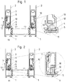
- Fig. 1
- eine nicht erfindungsgemäße Profilanordnung in einer Schnittansicht mit einer ersten Variante der Stanzschraube;
- Fig. 2
- eine erfindungsgemäße Profilanordnung in einer Schnittansicht mit einer zweiten Variante der Stanzschraube;
- Fig. 3
- eine Profilanordnung ohne Stanzschraube;
- Fig. 4
- eine perspektivische Darstellung einer erfindungsgemäßen Profilanordnung;
- Fig. 5
- eine Stanzschraube in einer Seitenansicht;
- Fig. 6
- eine Stanzschraube in einer Draufsicht.
- Folgende Bezugszeichen werden in den Abbildungen verwendet:
- 1
- erstes Profil
- 2
- zweites Profil
- 3
- Stoßverbinder
- 4
- T-förmiges Profil
- 5
- C-förmige Nut
- 6
- erster Haken
- 7
- zweiter Haken
- 8
- erster Haken
- 9
- zweiter Haken
- 10
- Stanzschraube
- 11
- Öffnung
- 12
- Gewindebohrung
- 13
- Druckrichtung
- 101
- Schraubenkopf
- 102
- Gewindeabschnitt
- 103
- konischer Abschnitt
- 104
- Stanzzapfen
- Eine Profilanordnung umfasst im Wesentlichen ein erstes Profil 1, ein zweites Profil 2 und einen zwischen den Profilen angeordneten Stoßverbinder 3.
- Bei dem ersten Profil 1 und dem zweiten Profil 2 handelt es sich vorzugsweise um längliche Profile, insbesondere Hohlprofile, vorzugsweise aus Aluminium. Das zweite Profil 2 steht vorzugsweise senkrecht auf dem ersten Profil 1 und weist zumindest einen Hohlprofilabschnitt bzw. eine Hohlkammer auf.
- Bei dem Stoßverbinder 3 handelt es sich um ein Formteil, welches an dem ersten Profil 1 befestigt, in die Hohlkammer des zweiten Profils 2 eingeschoben und an dem zweiten Profil 2 befestigt werden kann. In der Regel handelt es sich bei dem Stoßverbinder 3 um ein bearbeitetes stranggepresstes Profil aus beispielsweise Aluminium mit einem im Wesentlichen rechteckförmigen Querschnitt.
- Das erste Profil 1 und der Stoßverbinder 3 sind mit Verbindungsmitteln zur Verbindung miteinander ausgestattet. Vorzugsweise gehen Profil 1 und Stoßverbinder 3 mit diesen Verbindungsmitteln eine formschlüssige Verbindung ein. Es kann beispielsweise vorgesehen sein, dass die Verbindungsmittel einen im Querschnitt T-förmigen Abschnitt 4, beispielsweise des Stoßverbinders 3, und eine im Querschnitt C-förmige Nut 5, beispielsweise in dem ersten Profil 1, umfassen. Der Stoßverbinder 3 kann entsprechend auf das erste Profil 1 aufgeschoben werden.
- Alternativ können die Verbindungsmittel auch einen ersten Haken 6 und einen zweiten Haken 7 an dem ersten Profil 1, sowie einen ersten Haken 8 und einen zweiten Haken 9 an dem Stoßverbinder 3 umfassen. Die Haken 8, 9 des Stoßverbinders 3 können auf unterschiedlichen Höhen des Stoßverbinders 3 angeordnet sein. Entsprechend sind auch die korrespondierenden Haken 6, 7 des Profils 1 auf unterschiedlichen Höhen angeordnet.
- Im Wesentlichen kommt es darauf an, dass die Verbindungsmittel eine formschlüssige Verbindung des Stoßverbinders 3 mit dem ersten Profil 1 ermöglichen.
- Im Ergebnis steht der Stoßverbinder 3 senkrecht auf dem ersten Profil 1. Der Stoßverbinder ist über hier nicht dargestellte Verbindungsmittel mit dem zweiten Profil 2 verbunden.
- Die Profilanordnung ist ferner mit einer Stanzschraube 10 ausgestattet. Die Stanzschraube 10 umfasst in Längsrichtung hintereinander einen Schraubenkopf 101 mit einem Werkzeuganschluss, einen Gewindeabschnitt 102, einen konischen Abschnitt 103 und einen Stanzzapfen 104.
- Der Schraubenkopf 101 und der Gewindeabschnitt 102 sind mit einer herkömmlichen Schraube vergleichbar. Der konische Abschnitt 103 ist konisch ausgebildet und verjüngt sich im Wesentlichen von dem Durchmesser des Gewindeabschnitts 102 zu dem gegenüber dem Gewindeabschnitt geringeren Durchmesser des Stanzzapfens 104. Der Stanzzapfen 104 als solches ist konisch oder kegelförmig ausgebildet Die Stanzschraube 10 wird grundsätzlich in den Stoßverbinder 3 eingedreht. Hierzu kann beispielsweise eine Gewindebohrung 12 in dem Stoßverbinder 3 vorgesehen sein. Soweit der Stoßverbinder 3 in der angedachten Position gegenüber dem ersten Profil 1 in der hierfür vorgesehenen formschlüssigen Verbindung angeordnet ist, durchstößt der Stanzzapfen 104 beim Hineindrehen der Stanzschraube 10 in die Gewindebohrung 12 die Wandung des ersten Profils 1 und schafft entsprechend eine Öffnung 11 in der Wandung des ersten Profils 1. Hierdurch wird eine exakte Positionierung des Stoßverbinders 3 sichergestellt. Gleichwohl wird die Stanzschraube 10 so weit weiter eingedreht, bis der konische Abschnitt 103 auf dem Rand der Öffnung 11 des ersten Profils 1 aufliegt. Durch die konische Ausgestaltung des konischen Abschnitts 103 wird ein fester Sitz des Stoßverbinders 3 erreicht. Beim Hineindrehen der Stanzschraube 10 wird ein Druck, angedeutet durch den Pfeil 13, gegen die formschlüssige Verbindung erzeugt, der den Stoßverbinder 3 in die formschlüssige Verbindung hineindrückt und dadurch einen festen Sitz sicherstellt.
Claims (8)
- Profilanordnung, umfassend- ein erstes Profil (1), ein zweites Profil (2) und einen Stoßverbinder (3), wobei- der Stoßverbinder (3) senkrecht auf dem ersten Profil (1) angebracht ist, wobei- das zweite Profil (2) zumindest abschnittsweise eine Hohlkammer umfasst, wobei der Stoßverbinder (3) in die Hohlkammer eingesteckt ist, wobei- der Stoßverbinder (3) und das erste Profil (1) mit formschlüssigen Verbindungsmitteln miteinander verbunden sind, wobei- eine Stanzschraube (10) mit einem Gewindeabschnitt (102) und einem Stanzzapfen (104) in den Stoßverbinder (3) eingeschraubt ist, wobei- der Stanzzapfen (104) in einer Öffnung (11) des ersten Profils (1) angeordnet ist,dadurch gekennzeichnet, dass
die Stanzschraube (10) mit einem konischen Abschnitt (103) zwischen dem Gewindeabschnitt (102) und dem Stanzzapfen (104) ausgestattet ist, wobei der Stanzzapfen (104) konisch oder kegelförmig ausgebildet ist. - Profilanordnung nach Anspruch 1, dadurch gekennzeichnet, dass das zweite Profil (2) senkrecht auf dem ersten Profil (1) angeordnet ist.
- Profilanordnung nach mindestens einem der vorhergehenden Ansprüche, dadurch gekennzeichnet, dass es sich bei dem zweiten Profil (2) um ein Aluminiumhohlprofil handelt.
- Profilanordnung nach mindestens einem der vorhergehenden Ansprüche, dadurch gekennzeichnet, dass es sich bei dem Stoßverbinder (3) um einen bearbeiteten Aluminiumprofilabschnitt, vorzugsweise aus einem Aluminiumstrangpressprofil, handelt.
- Profilanordnung nach mindestens einem der vorhergehenden Ansprüche, dadurch gekennzeichnet, dass die formschlüssigen Verbindungsmittel ein T-förmiges Profil (4) und eine C-förmige Nut (5) umfassen.
- Profilanordnung nach mindestens einem der vorhergehenden Ansprüche, dadurch gekennzeichnet, dass die formschlüssigen Verbindungsmittel ein dem ersten Profil (1) zugeordneten ersten Haken (6) und zweiten Haken (7), sowie einen dem Stoßverbinder (3) zugeordneten ersten Haken (8) und zweiten Haken (9) umfasst.
- Profilanordnung nach mindestens einem der vorhergehenden Ansprüche, dadurch gekennzeichnet, dass der Durchmesser des Gewindeabschnitts (102) der Stanzschraube (10) größer als der Durchmesser des Stanzzapfens (104) ist.
- Profilanordnung nach mindestens einem der vorhergehenden Ansprüche, dadurch gekennzeichnet, dass sich der konische Abschnitt (103) von dem Gewindeabschnitt (102) zu dem Stanzzapfen (104) verjüngt.
Applications Claiming Priority (1)
| Application Number | Priority Date | Filing Date | Title |
|---|---|---|---|
| DE102014111089.7A DE102014111089A1 (de) | 2014-08-05 | 2014-08-05 | Profilanordnung |
Publications (2)
| Publication Number | Publication Date |
|---|---|
| EP2982825A1 EP2982825A1 (de) | 2016-02-10 |
| EP2982825B1 true EP2982825B1 (de) | 2018-09-19 |
Family
ID=53871847
Family Applications (1)
| Application Number | Title | Priority Date | Filing Date |
|---|---|---|---|
| EP15178885.8A Active EP2982825B1 (de) | 2014-08-05 | 2015-07-29 | Profilanordnung |
Country Status (2)
| Country | Link |
|---|---|
| EP (1) | EP2982825B1 (de) |
| DE (1) | DE102014111089A1 (de) |
Citations (1)
| Publication number | Priority date | Publication date | Assignee | Title |
|---|---|---|---|---|
| DE2500937A1 (de) * | 1975-01-11 | 1976-07-15 | Uhl Kg Geb | Eck- oder sprossenverbindung von rahmenprofilen |
Family Cites Families (5)
| Publication number | Priority date | Publication date | Assignee | Title |
|---|---|---|---|---|
| ES253459Y (es) * | 1978-11-10 | 1982-04-16 | Fijador clinico externo, de elevada estabilidad, para reduc-cion de fracturas. | |
| DE19522044A1 (de) * | 1995-06-17 | 1996-12-19 | Schueco Int Kg | Eck- oder T-Verbindung an Rahmen oder Gestellen |
| DE10101201A1 (de) * | 2001-01-11 | 2002-08-01 | Wicona Bausysteme Gmbh | Verbinder mit Stanzschraube |
| DE10151061A1 (de) * | 2001-10-16 | 2003-04-30 | Wicona Bausysteme Gmbh | Profilstoßverbinder |
| DE102012006899B4 (de) * | 2012-04-05 | 2025-03-27 | Heroal - Johann Henkenjohann Gmbh & Co. Kg | Stoßverbindung vorzugsweise eines Fensterrahmens |
-
2014
- 2014-08-05 DE DE102014111089.7A patent/DE102014111089A1/de not_active Withdrawn
-
2015
- 2015-07-29 EP EP15178885.8A patent/EP2982825B1/de active Active
Patent Citations (1)
| Publication number | Priority date | Publication date | Assignee | Title |
|---|---|---|---|---|
| DE2500937A1 (de) * | 1975-01-11 | 1976-07-15 | Uhl Kg Geb | Eck- oder sprossenverbindung von rahmenprofilen |
Also Published As
| Publication number | Publication date |
|---|---|
| DE102014111089A1 (de) | 2016-02-11 |
| EP2982825A1 (de) | 2016-02-10 |
Similar Documents
| Publication | Publication Date | Title |
|---|---|---|
| EP2132006B1 (de) | Mehrteiliger stiftzieher zum herausziehen eines stifts oder bolzens aus einem loch eines bauteils | |
| EP1297596B1 (de) | Anschlussarmatur mit elastischem ring als anschlag | |
| EP3057395B1 (de) | Scharspitze bzw. werkzeugkombination mit einer scharspitze | |
| EP2742199B1 (de) | Befestigungsanordnung zur befestigung eines bauteils an einer nut eines fensters, einer tür oder dergleichen | |
| DE102013214247A1 (de) | Blindnietmutter für die Verbindung zweier Bauteile | |
| EP3097313A1 (de) | Schraube, befestigungsanordnung und verwendung einer schraube | |
| EP2827006A1 (de) | Blindnietsystem | |
| EP2982874B1 (de) | Schraubdom zum befestigen eines bauteils | |
| EP2379260B1 (de) | Werkzeug für die spanende bearbeitung, insbesondere langdrehwerkzeug | |
| EP3110587B1 (de) | Lötspitzenbefestigungssystem | |
| EP3167163B1 (de) | Radscheibenanordnung | |
| DE102011106436A1 (de) | Befestigungsvorrichtung | |
| EP3472415B1 (de) | Scharniersystem | |
| EP3196380B1 (de) | Verbindungsmittel, handlauf, sowie verfahren zur herstellung eines verbindungsmittels | |
| DE102013110963A1 (de) | Handlaufträger und Handlauf | |
| EP2982825A1 (de) | Profilanordnung | |
| EP3667106A1 (de) | Funktionselement, zusammenbauteil und verfahren zur herstellung des zusammenbauteils | |
| DE29603389U1 (de) | Schnellverschluß | |
| DE102010055808A1 (de) | Befestigungsvorrichtung | |
| DE102009027473A1 (de) | Klemmverbindung | |
| DE202007015154U1 (de) | System zur Befestigung eines Beschlagteils an einem Hohlprofil | |
| DE102013210905A1 (de) | Schraubverbindung von mindestens zwei aneinander anliegenden Bauteilen | |
| DE202008001361U1 (de) | Dübelbolzen einer Verbindungsvorrichtung | |
| DE102015216546B4 (de) | Schraube zum Direktverschrauben mehrerer Bauteile, Bauteileverbund und Verfahren zum Herstellen eines Bauteileverbunds | |
| WO2017153569A1 (de) | Hülse zum einbringen in eine öffnung |
Legal Events
| Date | Code | Title | Description |
|---|---|---|---|
| PUAI | Public reference made under article 153(3) epc to a published international application that has entered the european phase |
Free format text: ORIGINAL CODE: 0009012 |
|
| AK | Designated contracting states |
Kind code of ref document: A1 Designated state(s): AL AT BE BG CH CY CZ DE DK EE ES FI FR GB GR HR HU IE IS IT LI LT LU LV MC MK MT NL NO PL PT RO RS SE SI SK SM TR |
|
| AX | Request for extension of the european patent |
Extension state: BA ME |
|
| 17P | Request for examination filed |
Effective date: 20160810 |
|
| RAV | Requested validation state of the european patent: fee paid |
Extension state: MA Effective date: 20160810 |
|
| RAX | Requested extension states of the european patent have changed |
Extension state: BA Payment date: 20160810 Extension state: ME Payment date: 20160810 |
|
| RBV | Designated contracting states (corrected) |
Designated state(s): AL AT BE BG CH CY CZ DE DK EE ES FI FR GB GR HR HU IE IS IT LI LT LU LV MC MK MT NL NO PL PT RO RS SE SI SK SM TR |
|
| STAA | Information on the status of an ep patent application or granted ep patent |
Free format text: STATUS: EXAMINATION IS IN PROGRESS |
|
| 17Q | First examination report despatched |
Effective date: 20170203 |
|
| REG | Reference to a national code |
Ref country code: DE Ref legal event code: R079 Ref document number: 502015005944 Country of ref document: DE Free format text: PREVIOUS MAIN CLASS: E06B0003964000 Ipc: E06B0003968000 |
|
| GRAP | Despatch of communication of intention to grant a patent |
Free format text: ORIGINAL CODE: EPIDOSNIGR1 |
|
| STAA | Information on the status of an ep patent application or granted ep patent |
Free format text: STATUS: GRANT OF PATENT IS INTENDED |
|
| RIC1 | Information provided on ipc code assigned before grant |
Ipc: E06B 3/968 20060101AFI20180308BHEP Ipc: E06B 3/964 20060101ALI20180308BHEP |
|
| INTG | Intention to grant announced |
Effective date: 20180403 |
|
| GRAS | Grant fee paid |
Free format text: ORIGINAL CODE: EPIDOSNIGR3 |
|
| GRAA | (expected) grant |
Free format text: ORIGINAL CODE: 0009210 |
|
| STAA | Information on the status of an ep patent application or granted ep patent |
Free format text: STATUS: THE PATENT HAS BEEN GRANTED |
|
| AK | Designated contracting states |
Kind code of ref document: B1 Designated state(s): AL AT BE BG CH CY CZ DE DK EE ES FI FR GB GR HR HU IE IS IT LI LT LU LV MC MK MT NL NO PL PT RO RS SE SI SK SM TR |
|
| REG | Reference to a national code |
Ref country code: GB Ref legal event code: FG4D Free format text: NOT ENGLISH |
|
| REG | Reference to a national code |
Ref country code: CH Ref legal event code: EP |
|
| REG | Reference to a national code |
Ref country code: AT Ref legal event code: REF Ref document number: 1043458 Country of ref document: AT Kind code of ref document: T Effective date: 20181015 |
|
| REG | Reference to a national code |
Ref country code: IE Ref legal event code: FG4D Free format text: LANGUAGE OF EP DOCUMENT: GERMAN |
|
| REG | Reference to a national code |
Ref country code: DE Ref legal event code: R096 Ref document number: 502015005944 Country of ref document: DE |
|
| REG | Reference to a national code |
Ref country code: CH Ref legal event code: NV Representative=s name: WAGNER + HELBIG PATENTANWAELTE CONSEILS EN PRO, CH |
|
| REG | Reference to a national code |
Ref country code: NL Ref legal event code: MP Effective date: 20180919 |
|
| PG25 | Lapsed in a contracting state [announced via postgrant information from national office to epo] |
Ref country code: NO Free format text: LAPSE BECAUSE OF FAILURE TO SUBMIT A TRANSLATION OF THE DESCRIPTION OR TO PAY THE FEE WITHIN THE PRESCRIBED TIME-LIMIT Effective date: 20181219 Ref country code: BG Free format text: LAPSE BECAUSE OF FAILURE TO SUBMIT A TRANSLATION OF THE DESCRIPTION OR TO PAY THE FEE WITHIN THE PRESCRIBED TIME-LIMIT Effective date: 20181219 Ref country code: LT Free format text: LAPSE BECAUSE OF FAILURE TO SUBMIT A TRANSLATION OF THE DESCRIPTION OR TO PAY THE FEE WITHIN THE PRESCRIBED TIME-LIMIT Effective date: 20180919 Ref country code: GR Free format text: LAPSE BECAUSE OF FAILURE TO SUBMIT A TRANSLATION OF THE DESCRIPTION OR TO PAY THE FEE WITHIN THE PRESCRIBED TIME-LIMIT Effective date: 20181220 Ref country code: SE Free format text: LAPSE BECAUSE OF FAILURE TO SUBMIT A TRANSLATION OF THE DESCRIPTION OR TO PAY THE FEE WITHIN THE PRESCRIBED TIME-LIMIT Effective date: 20180919 Ref country code: RS Free format text: LAPSE BECAUSE OF FAILURE TO SUBMIT A TRANSLATION OF THE DESCRIPTION OR TO PAY THE FEE WITHIN THE PRESCRIBED TIME-LIMIT Effective date: 20180919 Ref country code: FI Free format text: LAPSE BECAUSE OF FAILURE TO SUBMIT A TRANSLATION OF THE DESCRIPTION OR TO PAY THE FEE WITHIN THE PRESCRIBED TIME-LIMIT Effective date: 20180919 |
|
| REG | Reference to a national code |
Ref country code: LT Ref legal event code: MG4D |
|
| PG25 | Lapsed in a contracting state [announced via postgrant information from national office to epo] |
Ref country code: AL Free format text: LAPSE BECAUSE OF FAILURE TO SUBMIT A TRANSLATION OF THE DESCRIPTION OR TO PAY THE FEE WITHIN THE PRESCRIBED TIME-LIMIT Effective date: 20180919 Ref country code: LV Free format text: LAPSE BECAUSE OF FAILURE TO SUBMIT A TRANSLATION OF THE DESCRIPTION OR TO PAY THE FEE WITHIN THE PRESCRIBED TIME-LIMIT Effective date: 20180919 Ref country code: HR Free format text: LAPSE BECAUSE OF FAILURE TO SUBMIT A TRANSLATION OF THE DESCRIPTION OR TO PAY THE FEE WITHIN THE PRESCRIBED TIME-LIMIT Effective date: 20180919 |
|
| PG25 | Lapsed in a contracting state [announced via postgrant information from national office to epo] |
Ref country code: EE Free format text: LAPSE BECAUSE OF FAILURE TO SUBMIT A TRANSLATION OF THE DESCRIPTION OR TO PAY THE FEE WITHIN THE PRESCRIBED TIME-LIMIT Effective date: 20180919 Ref country code: NL Free format text: LAPSE BECAUSE OF FAILURE TO SUBMIT A TRANSLATION OF THE DESCRIPTION OR TO PAY THE FEE WITHIN THE PRESCRIBED TIME-LIMIT Effective date: 20180919 Ref country code: PL Free format text: LAPSE BECAUSE OF FAILURE TO SUBMIT A TRANSLATION OF THE DESCRIPTION OR TO PAY THE FEE WITHIN THE PRESCRIBED TIME-LIMIT Effective date: 20180919 Ref country code: IS Free format text: LAPSE BECAUSE OF FAILURE TO SUBMIT A TRANSLATION OF THE DESCRIPTION OR TO PAY THE FEE WITHIN THE PRESCRIBED TIME-LIMIT Effective date: 20190119 Ref country code: CZ Free format text: LAPSE BECAUSE OF FAILURE TO SUBMIT A TRANSLATION OF THE DESCRIPTION OR TO PAY THE FEE WITHIN THE PRESCRIBED TIME-LIMIT Effective date: 20180919 Ref country code: IT Free format text: LAPSE BECAUSE OF FAILURE TO SUBMIT A TRANSLATION OF THE DESCRIPTION OR TO PAY THE FEE WITHIN THE PRESCRIBED TIME-LIMIT Effective date: 20180919 Ref country code: RO Free format text: LAPSE BECAUSE OF FAILURE TO SUBMIT A TRANSLATION OF THE DESCRIPTION OR TO PAY THE FEE WITHIN THE PRESCRIBED TIME-LIMIT Effective date: 20180919 Ref country code: ES Free format text: LAPSE BECAUSE OF FAILURE TO SUBMIT A TRANSLATION OF THE DESCRIPTION OR TO PAY THE FEE WITHIN THE PRESCRIBED TIME-LIMIT Effective date: 20180919 |
|
| PG25 | Lapsed in a contracting state [announced via postgrant information from national office to epo] |
Ref country code: SK Free format text: LAPSE BECAUSE OF FAILURE TO SUBMIT A TRANSLATION OF THE DESCRIPTION OR TO PAY THE FEE WITHIN THE PRESCRIBED TIME-LIMIT Effective date: 20180919 Ref country code: SM Free format text: LAPSE BECAUSE OF FAILURE TO SUBMIT A TRANSLATION OF THE DESCRIPTION OR TO PAY THE FEE WITHIN THE PRESCRIBED TIME-LIMIT Effective date: 20180919 Ref country code: PT Free format text: LAPSE BECAUSE OF FAILURE TO SUBMIT A TRANSLATION OF THE DESCRIPTION OR TO PAY THE FEE WITHIN THE PRESCRIBED TIME-LIMIT Effective date: 20190119 |
|
| REG | Reference to a national code |
Ref country code: DE Ref legal event code: R097 Ref document number: 502015005944 Country of ref document: DE |
|
| REG | Reference to a national code |
Ref country code: DE Ref legal event code: R082 Ref document number: 502015005944 Country of ref document: DE Representative=s name: MEISSNER BOLTE PATENTANWAELTE RECHTSANWAELTE P, DE |
|
| PLBE | No opposition filed within time limit |
Free format text: ORIGINAL CODE: 0009261 |
|
| STAA | Information on the status of an ep patent application or granted ep patent |
Free format text: STATUS: NO OPPOSITION FILED WITHIN TIME LIMIT |
|
| PG25 | Lapsed in a contracting state [announced via postgrant information from national office to epo] |
Ref country code: DK Free format text: LAPSE BECAUSE OF FAILURE TO SUBMIT A TRANSLATION OF THE DESCRIPTION OR TO PAY THE FEE WITHIN THE PRESCRIBED TIME-LIMIT Effective date: 20180919 |
|
| 26N | No opposition filed |
Effective date: 20190620 |
|
| PG25 | Lapsed in a contracting state [announced via postgrant information from national office to epo] |
Ref country code: SI Free format text: LAPSE BECAUSE OF FAILURE TO SUBMIT A TRANSLATION OF THE DESCRIPTION OR TO PAY THE FEE WITHIN THE PRESCRIBED TIME-LIMIT Effective date: 20180919 |
|
| PGFP | Annual fee paid to national office [announced via postgrant information from national office to epo] |
Ref country code: CH Payment date: 20190826 Year of fee payment: 5 |
|
| PG25 | Lapsed in a contracting state [announced via postgrant information from national office to epo] |
Ref country code: MC Free format text: LAPSE BECAUSE OF FAILURE TO SUBMIT A TRANSLATION OF THE DESCRIPTION OR TO PAY THE FEE WITHIN THE PRESCRIBED TIME-LIMIT Effective date: 20180919 |
|
| PG25 | Lapsed in a contracting state [announced via postgrant information from national office to epo] |
Ref country code: TR Free format text: LAPSE BECAUSE OF FAILURE TO SUBMIT A TRANSLATION OF THE DESCRIPTION OR TO PAY THE FEE WITHIN THE PRESCRIBED TIME-LIMIT Effective date: 20180919 |
|
| REG | Reference to a national code |
Ref country code: BE Ref legal event code: MM Effective date: 20190731 |
|
| PG25 | Lapsed in a contracting state [announced via postgrant information from national office to epo] |
Ref country code: BE Free format text: LAPSE BECAUSE OF NON-PAYMENT OF DUE FEES Effective date: 20190731 Ref country code: LU Free format text: LAPSE BECAUSE OF NON-PAYMENT OF DUE FEES Effective date: 20190729 |
|
| PG25 | Lapsed in a contracting state [announced via postgrant information from national office to epo] |
Ref country code: IE Free format text: LAPSE BECAUSE OF NON-PAYMENT OF DUE FEES Effective date: 20190729 |
|
| REG | Reference to a national code |
Ref country code: CH Ref legal event code: PL |
|
| PG25 | Lapsed in a contracting state [announced via postgrant information from national office to epo] |
Ref country code: CH Free format text: LAPSE BECAUSE OF NON-PAYMENT OF DUE FEES Effective date: 20200731 Ref country code: LI Free format text: LAPSE BECAUSE OF NON-PAYMENT OF DUE FEES Effective date: 20200731 |
|
| PG25 | Lapsed in a contracting state [announced via postgrant information from national office to epo] |
Ref country code: CY Free format text: LAPSE BECAUSE OF FAILURE TO SUBMIT A TRANSLATION OF THE DESCRIPTION OR TO PAY THE FEE WITHIN THE PRESCRIBED TIME-LIMIT Effective date: 20180919 |
|
| PG25 | Lapsed in a contracting state [announced via postgrant information from national office to epo] |
Ref country code: MT Free format text: LAPSE BECAUSE OF FAILURE TO SUBMIT A TRANSLATION OF THE DESCRIPTION OR TO PAY THE FEE WITHIN THE PRESCRIBED TIME-LIMIT Effective date: 20180919 Ref country code: HU Free format text: LAPSE BECAUSE OF FAILURE TO SUBMIT A TRANSLATION OF THE DESCRIPTION OR TO PAY THE FEE WITHIN THE PRESCRIBED TIME-LIMIT; INVALID AB INITIO Effective date: 20150729 |
|
| REG | Reference to a national code |
Ref country code: AT Ref legal event code: MM01 Ref document number: 1043458 Country of ref document: AT Kind code of ref document: T Effective date: 20200729 |
|
| PG25 | Lapsed in a contracting state [announced via postgrant information from national office to epo] |
Ref country code: AT Free format text: LAPSE BECAUSE OF NON-PAYMENT OF DUE FEES Effective date: 20200729 |
|
| PG25 | Lapsed in a contracting state [announced via postgrant information from national office to epo] |
Ref country code: MK Free format text: LAPSE BECAUSE OF FAILURE TO SUBMIT A TRANSLATION OF THE DESCRIPTION OR TO PAY THE FEE WITHIN THE PRESCRIBED TIME-LIMIT Effective date: 20180919 |
|
| PGFP | Annual fee paid to national office [announced via postgrant information from national office to epo] |
Ref country code: GB Payment date: 20250519 Year of fee payment: 11 |
|
| PGFP | Annual fee paid to national office [announced via postgrant information from national office to epo] |
Ref country code: FR Payment date: 20250516 Year of fee payment: 11 |
|
| PGFP | Annual fee paid to national office [announced via postgrant information from national office to epo] |
Ref country code: DE Payment date: 20250618 Year of fee payment: 11 |