EP2982271B1 - Child-care swing - Google Patents
Child-care swing Download PDFInfo
- Publication number
- EP2982271B1 EP2982271B1 EP15180102.4A EP15180102A EP2982271B1 EP 2982271 B1 EP2982271 B1 EP 2982271B1 EP 15180102 A EP15180102 A EP 15180102A EP 2982271 B1 EP2982271 B1 EP 2982271B1
- Authority
- EP
- European Patent Office
- Prior art keywords
- support
- members
- relative
- chair
- seat
- Prior art date
- Legal status (The legal status is an assumption and is not a legal conclusion. Google has not performed a legal analysis and makes no representation as to the accuracy of the status listed.)
- Active
Links
Images


Classifications
-
- A—HUMAN NECESSITIES
- A47—FURNITURE; DOMESTIC ARTICLES OR APPLIANCES; COFFEE MILLS; SPICE MILLS; SUCTION CLEANERS IN GENERAL
- A47D—FURNITURE SPECIALLY ADAPTED FOR CHILDREN
- A47D1/00—Children's chairs
- A47D1/002—Children's chairs adjustable
- A47D1/004—Children's chairs adjustable in height
-
- A—HUMAN NECESSITIES
- A47—FURNITURE; DOMESTIC ARTICLES OR APPLIANCES; COFFEE MILLS; SPICE MILLS; SUCTION CLEANERS IN GENERAL
- A47D—FURNITURE SPECIALLY ADAPTED FOR CHILDREN
- A47D1/00—Children's chairs
- A47D1/02—Foldable chairs
- A47D1/023—Foldable chairs of high chair type
-
- A—HUMAN NECESSITIES
- A47—FURNITURE; DOMESTIC ARTICLES OR APPLIANCES; COFFEE MILLS; SPICE MILLS; SUCTION CLEANERS IN GENERAL
- A47D—FURNITURE SPECIALLY ADAPTED FOR CHILDREN
- A47D9/00—Cradles ; Bassinets
- A47D9/005—Cradles ; Bassinets foldable
-
- A—HUMAN NECESSITIES
- A47—FURNITURE; DOMESTIC ARTICLES OR APPLIANCES; COFFEE MILLS; SPICE MILLS; SUCTION CLEANERS IN GENERAL
- A47D—FURNITURE SPECIALLY ADAPTED FOR CHILDREN
- A47D9/00—Cradles ; Bassinets
- A47D9/012—Cradles ; Bassinets with adjustable parts
Definitions
- the present invention relates to a transat childcare.
- a baby lounger that is to say a lounger comprising a seat for accommodating the child in a supine or sitting position.
- the seat is mounted on a support comprising support members on the ground.
- the support maintains the seat in a relatively low position, at ground level, which ensures good stability of the recliner but does not allow adults to interact easily with the child, for example at the table.
- the child it is sometimes desirable for the child to be raised above the ground.
- CH-A-270 503 discloses a nursery furniture, including a child receiving basket.
- This nacelle is carried by a support including two upper limbs, each U-shaped, and two lower limbs, each also U-shaped, the free ends of the aforementioned four members being articulated in rotation on two side plates.
- each lower member carries, in a rotational manner, an additional member, which is also U-shaped.
- These additional members are only supported on the ground in a raised position of the cabinet. in a lowered position of this piece of furniture, the additional members are retracted between the lower limbs so that it is these lower limbs which are then directly resting on the ground and not the additional limbs.
- CH-A-270 503 It is precisely to equip the lower limbs, serving as support feet on the ground, with the additional limbs which, by articulation, pass from a retraction configuration (the additional limbs are then erased in the lower limbs) to a deployed configuration (the additional members "lengthen” the lower limbs).
- the manipulation to be performed at the two additional members, sometimes deployed, sometimes retracted, is tedious and impractical, or potentially a source of imbalances of the nacelle and therefore accidents.
- GB-A-210,846 on which is based the preamble of claim 1, discloses a baby chair, comprising a seat and a support for this seat.
- Four Floor support members are provided to support the support. Each member is articulated in rotation on the support, so as to modify, in an adjustable manner, the height of the seat relative to the ground.
- the two members that are arranged on the same side of the seat are not connected to the members on the other side of the seat, so that the change of the elevation of the seat is tedious and source of potential imbalances of the chair.
- the object of the present invention is to provide a child's recliner, which allows to change the level of elevation of its seat in a convenient and safe manner.
- the subject of the invention is a child-care deckchair, as defined in claim 1.
- the passage between the high position and the low position is done in a simple and safe manner, by rotation of members which, in both positions, are both deployed downwardly relative to the seat support and in contact with the ground.
- the rotational articulation of the limbs advantageously makes it possible to fold easily and in a simplified way the limbs against the support, in a folded configuration having a small footprint.
- the Figures 1 to 8 show a lounger 1 for children, comprising a seat 5 for receiving the child.
- the seat 5 is made from fabric and / or foam, for the comfort of the child.
- a reducing cushion 51 ensures the maintenance of the child's head.
- the seat 5 is relatively flexible, and it is mounted on a rigid frame 4 which comprises a seat 41 and a backrest 42 together defining a closed contour of generally oval shape whose dimensions are adapted to support the seat 5.
- a fastening system for example self-gripping strips or a zipper makes it possible to fix the seat 5 to the frame 4 while allowing the seat to be removed from the seat 5.
- the seat 41 and the backrest 42 are each generally U-shaped, with two branches connected by a curved central portion.
- the armature 4 is held by a generally U-shaped seat support 3, or "lower arch”, comprising two upper support members 31 and 32, or “arms”, interconnected by a body 30.
- the free ends branches of the U-shape are oriented upwards and are fixed to the frame 4, at the connection between the seat 41 and the backrest 42, while the body 30 is located at the bottom relative to the branches.
- the seat 41 and the backrest 42 are connected to the support 3 by hinge-type pivoting means 43 arranged at each end of the branches of the U-shape.
- the body 30 supports at least three support members on the ground, for example four feet 21, 22, 23 and 24.
- the feet 21 and 22 are interconnected by a curved central portion which passes through the body 30, and together form a first arch 2A generally U-shaped.
- the feet 23 and 24 pass through the body 30 and form a second arch 2B.
- the free ends of the feet 21 to 24 are each equipped with a pad 20 articulated with the foot 21 to 24 corresponding, so as to ensure the stability of the support of the floor of the lounger 1.
- the lounger 1 comprises mechanical connection means between each leg 21 to 24 and the support 3. These means include two horizontal through openings 301A and 301B formed in the body 30, each receiving the curved central portion of one of the lower arches 2A and 2B.
- the mechanical connection means allow a rotation of the arches 2A and 2B relative to the support 3, centered on a horizontal axis X2A or X2B, respectively, defined by the openings 301A and 301B of the support 3.
- An articulation mechanism of the arches 2A and 2B with the support 3, visible at the figure 3 is housed inside the body 30.
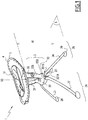
- This mechanism comprises two ovoid-shaped toothed wheels 33A and 33B, which cooperate with the arches 2A and 2B via one end of the feet 21 to 24 having an ovoid section and of the complementary ovoid shape of the two toothed wheels 33A and 33B.
- Means for blocking the position of the arches 2A and 2B relative to the support 3 are formed by the two toothed wheels 33A and 33B and locking systems of these wheels, actuated by the simultaneous action on locking buttons 35A and 35B respectively carried by the arms 31 and 32.
- the buttons 35A and 35B are for example each connected to a cable 36A or 36B housed inside the arm 31 or 32 corresponding.
- the cables 36A and 36B are connected to the locking systems of the gear wheels 33A and 33B.
- buttons 35A and 35B are movable between a locked position, in which they block the arches 2A and 2B in position relative to the support 3, and an unlocked position, in which they allow the movement of the arches 2A and 2B relative to the support 3
- the buttons 35A and 35B are in the locked position by default, and when pulled up, they move to the unlocked position.
- the manual actuation of the buttons 35A and 35B causes the unlocking of the locking means, which allows the rotation of the arches 2A and 2B relative to the support 3.
- the arches 2A and 2B are movable between at least two distinct positions, for example a first position, or high position, represented in FIGS. figures 1 , 2 , 4 , 7 and 8 , and a second position, or low position, represented at figure 5 .
- buttons 35A and 35B In the unlocked position of the buttons 35A and 35B, an operator can maneuver the arches 2A and 2B to move them from the high position to the low position.
- ⁇ is an angle defined between each leg 21 to 24 and a vertical plane P3 passing through the two arms 31 and 32 and the body 30 of the support 3.
- the plane P3 is parallel to the axes of rotation X2A and X2B of the feet 21 to 24.
- the feet 21 to 24 extend on both sides of the plane P3.
- the feet 21 and 22 extend from one side of the plane P3, and the feet 23 and 24 extend on the other side of the plane P3.
- H is a height of the seat 5, measured vertically between the outer bottom of the seat 5 and the ground S
- the angle a takes a first value ⁇ 1, equal to about 35 °, and the height H takes a first value H1 approximately equal to 70 cm.
- the first angle ⁇ 1 is between 30 ° and 40 °, and the first height H1 is between 70 and 80 cm.
- the angle ⁇ takes a second value ⁇ 2 strictly greater than the first value, and approximately equal to 70 °.
- the height H takes a second value H2 strictly lower than the first height H1 and approximately equal to 50 cm.
- the second angle ⁇ 2 is between 65 ° and 75 °, and the second height H2 is between 40 and 50 cm.
- the difference between the heights H1 and H2 is between 10 and 30 cm.
- the lounger 1 can be placed for example next to a sofa or a table.
- the child In the low position, the child is more close to the floor, for example at the height of a sofa. The low position can be used especially when the child is sleeping.
- the toothed wheels 33A and 33B mesh with each other, so that the angle ⁇ between the feet 21 and 22 of the first arch 2A and the plane P3 on the one hand, and the angle ⁇ between the feet 23 and 24 of the second arch 2B on the other hand, are always equal to each other.
- the toothed wheels 33A and 33B thus constitute or belong to means for synchronizing the angular position of the feet 21 to 24, which ensure a symmetrical deployment of the feet 21 to 24 with respect to the plane P3.
- buttons 35A and 35B when the buttons 35A and 35B are unlocked, the arches 2A and 2B are free to move, by gravity, from the high position to the low position or vice versa.
- the arches 2A and 2B simply pull on the two sliding buttons 35A and 35B and bring the support 3 from the ground, so as to spread the arches 2A and 2B l one of the other.
- to pass the arches 2A and 2B from the low position to the high position just simultaneously pull the buttons 35A and 35B and lift the support 3 to move it away from the ground, so that the arches 2A and 2B automatically recover by gravity, and rotate relative to the support 3 to move up.
- the seat 41 and the backrest 42 are articulated on the support 3 so as to independently author their inclination relative to the support 3, which allows to adjust the position of the child.
- the seat 41 by orienting the seat 41 in the extension of the backrest 42, the child adopts an extended position, while when the backrest 42 is inclined relative to the seat 41, the child is kept in a sitting position.
- the armature 4 has several positions.
- the backrest 42 has three distinct positions and the seat 41 has two distinct positions.
- the latter is equipped with blocking means 410, in the form of a lever-type button.
- Another lever 420 makes it possible to change the position backrest 42.
- the change of position of the seat 41 is done by pulling on the lever 410, and the change of position of the backrest 42 is done by pulling on the lever 420.
- These levers 410 and 420 are reassuring, they must be operated voluntarily to tilt the seat 41 or the backrest 42.
- the lounger 1 is intended to be folded into a configuration shown in FIG. figure 6 .
- the arches 2A and 2B are brought upwards, along the support 3, and the armature 4 is folded downwards along the support 3.
- the lounger 1 is compact when it is folded. In addition, this manipulation is easy.
- the armature 4 is equipped with two push buttons 38A and 38B, aligned with the common articulation axis X4 of the seat 41 and the backrest 42.
- the button 38A is disposed on a first side of the frame 4, on the seat 41, and the button 38B is disposed on the other side of the frame 4, on the back 42.
- the figures 1 , 2 , 4 , 5 , 7 and 8 show the lounger 1 in an expanded configuration, which is a configuration of use of the lounger 1, in which the arches 2A and 2B and the frame 4 respectively protrude downwards and upwards relative to the support 3.
- the passage of the folded configuration to the deployed configuration, and conversely, is effected by a rotation of the members 21 to 24 relative to the support 3.
- the recliner 1 comprises a natural rocking system, which allows the oscillation of the seat 5 relative to the feet 21 to 24. Additional locking means, activated by a button 50, allow the operator to block the system. natural swing.
- the arms 31 and 32 are articulated in rotation relative to the body 30 of the support 3, around a horizontal axis X30 tilting.
- a system of four ramps mounted on a circular piece blocks the swinging of the arms 31 and 32 relative to the body 30.
- a manual action on the button 50 rotates this circular piece, which removes the ramps and causes the Release of the swaying of the arms 31 and 32 relative to the body 30.
- the arms 31 and 32 then rest on an elastic damping member, for example springs or a silicone damper, which provides a freedom of swaying while maintaining a certain resistance.
- the means for blocking the position of the feet 21 to 24, the first locking means 35A and 35B and the natural balancing system are integrated in the support 30, which makes it possible to improve the compactness of the deckchair 1.
- the arches 2A and / or 2B are replaced by disjointed feet.
- the feet 21 to 24 are not connected to each other.
- the feet 21 to 24 may have an inverted L shape, with a vertical part for the support on the ground, and a horizontal part articulated in rotation with the support 3.
- the feet 21 to 24 are rotatable relative to the support 3 between a number of distinct positions greater than two, for example three, four or five positions, in which the height H of the seat 5 is different.
- the invention proposes predefined heights that make it possible to adapt the transat 1 to different situations.
- the armature 4 is removable, that is to say it can be detached from the support 3.
- the support 3 is in two parts hinged in rotation about a vertical axis, so as to allow the rotation of the armature 4 with respect to the legs 21 to 24 at 360 °.
- the upper part 30A of the body 30, which carries the arms 31 and 32 is able to rotate about a vertical axis X3 relative to the lower part 30B of the body 30, which carries the arches 2A and 2B, which allows the 360 ° rotation of the frame 4 and the arms 31 and 32 with respect to the arches 2A and 2B.
Description
La présente invention concerne un transat de puériculture.The present invention relates to a transat childcare.
Dans le domaine de la puériculture, il est connu d'utiliser un transat pour bébé, c'est-à-dire un transat comprenant un siège destiné à accueillir l'enfant en position couchée ou assise. Le siège est monté sur un support comprenant des membres d'appui sur le sol.In the field of childcare, it is known to use a baby lounger, that is to say a lounger comprising a seat for accommodating the child in a supine or sitting position. The seat is mounted on a support comprising support members on the ground.
De manière classique, le support maintient le siège dans une position relativement basse, au niveau du sol, ce qui assure une bonne stabilité du transat mais ne permet pas aux adultes d'interagir aisément avec l'enfant, par exemple à table. De plus, pour des questions d'hygiène, il est parfois souhaitable que l'enfant soit surélevé par rapport au sol.Conventionally, the support maintains the seat in a relatively low position, at ground level, which ensures good stability of the recliner but does not allow adults to interact easily with the child, for example at the table. In addition, for hygiene reasons, it is sometimes desirable for the child to be raised above the ground.
On connait des transats réglables en hauteur, où une position haute additionnelle permet d'élever le siège à une hauteur qui facilite les échanges entre l'enfant et les adultes. Toutefois, la manipulation à effectuer pour faire passer le transat de la position haute à la position basse, et inversement, est relativement fastidieuse, et ce transat est encombrant et difficile à transporter.We know adjustable chairs in height, where an additional high position allows to raise the seat to a height that facilitates exchanges between the child and adults. However, the manipulation to be made to move the deckchair from the high position to the low position, and vice versa, is relatively tedious, and this deckchair is bulky and difficult to transport.
De son côté,
Le but de la présente invention est de proposer un transat de puériculture, qui permette de modifier le niveau d'élévation de son siège de manière pratique et sûre.The object of the present invention is to provide a child's recliner, which allows to change the level of elevation of its seat in a convenient and safe manner.
A cet effet, l'invention a pour objet un transat de puériculture, tel que défini à la revendication 1.For this purpose, the subject of the invention is a child-care deckchair, as defined in
Grâce à l'invention, le passage entre la position haute et la position basse se fait de manière simple et sûre, par rotation de membres qui, dans les deux positions, sont à la fois déployés vers le bas par rapport au support du siège et au contact du sol. De plus, l'articulation en rotation des membres permet avantageusement de rabattre aisément et de manière simplifiée les membres contre le support, dans une configuration repliée ayant un encombrement faible.Thanks to the invention, the passage between the high position and the low position is done in a simple and safe manner, by rotation of members which, in both positions, are both deployed downwardly relative to the seat support and in contact with the ground. In addition, the rotational articulation of the limbs advantageously makes it possible to fold easily and in a simplified way the limbs against the support, in a folded configuration having a small footprint.
Des aspects avantageux mais non obligatoires de l'invention sont spécifiés aux revendications dépendantes.Advantageous but non-mandatory aspects of the invention are specified in the dependent claims.
L'invention sera mieux comprise et d'autres avantages de celle-ci ressortiront plus clairement à la lumière de la description qui va suivre d'un transat pour enfant conforme à son principe, donnée uniquement à titre d'exemple et faite en référence aux dessins dans lesquels :
- la
figure 1 est une vue en perspective d'un transat pour enfant conforme à l'invention, dans une position haute ; - la
figure 2 est une vue latérale en coupe partielle du transat de lafigure 1 ; - la
figure 3 est une vue, à plus grande échelle, du détail III à lafigure 2 ; - la
figure 4 est une vue de face et en coupe du transat de lafigure 1 ; - la
figure 5 est une vue latérale du transat de lafigure 1 , dans une position basse ; - la
figure 6 est une vue latérale du transat de lafigure 1 dans une configuration repliée ; - la
figure 7 est une vue latérale du transat de lafigure 1 montrant une fonction de balancement naturel ; et - la
figure 8 est une vue latérale du transat de lafigure 1 montrant une fonction d'inclinaison d'une assise et d'un dossier du transat.
- the
figure 1 is a perspective view of a child's lounger according to the invention, in a high position; - the
figure 2 is a partial sectional side view of the deckchair of thefigure 1 ; - the
figure 3 is a view, on a larger scale, of detail III tofigure 2 ; - the
figure 4 is a front view and in section of the deckchair of thefigure 1 ; - the
figure 5 is a side view of the lounger of thefigure 1 in a low position; - the
figure 6 is a side view of the lounger of thefigure 1 in a collapsed configuration; - the
figure 7 is a side view of the lounger of thefigure 1 showing a natural swing function; and - the
figure 8 is a side view of the lounger of thefigure 1 showing a function of inclination of a seat and a backrest of the deckchair.
Les
Le siège 5 est relativement souple, et il est monté sur une armature 4 rigide qui comprend une assise 41 et un dossier 42 définissant ensemble un contour fermé de forme globalement ovale dont les dimensions sont adaptées pour supporter le siège 5. Un système de fixation, par exemple des bandes auto-agrippantes ou une fermeture-éclair permet de fixer le siège 5 à l'armature 4 tout en autorisant le déhoussage du siège 5.The seat 5 is relatively flexible, and it is mounted on a
L'assise 41 et le dossier 42 sont chacun globalement en forme de U, avec deux branches reliées par une partie centrale courbe.The
L'armature 4 est maintenue par un support de siège 3, ou « arche inférieure » globalement en forme de U, comprenant deux membres supérieurs de support 31 et 32, ou « bras », reliés entre eux par un corps 30. Les extrémités libres des branches de la forme en U sont orientées vers le haut et sont fixées à l'armature 4, au niveau de la liaison entre l'assise 41 et le dossier 42, tandis que le corps 30 est situé en bas par rapport aux branches.The
L'assise 41 et le dossier 42 sont reliés au support 3 par des moyens d'articulation en rotation 43 de type charnière disposés au niveau de chaque extrémité des branches de la forme en U.The
Le corps 30 supporte au moins trois membres d'appui au sol, par exemple quatre pieds 21, 22, 23 et 24. Les pieds 21 et 22 sont reliés entre eux par une partie centrale courbe qui traverse le corps 30, et forment ensemble une première arche 2A globalement en forme de U. De même, les pieds 23 et 24 traversent le corps 30 et forment une deuxième arche 2B.The
Les extrémités libres des pieds 21 à 24 sont chacune équipées d'un patin 20 articulé avec le pied 21 à 24 correspondant, de manière à assurer la stabilité de l'appui au sol du transat 1.The free ends of the
Le transat 1 comprend des moyens de liaison mécanique entre chaque pied 21 à 24 et le support 3. Ces moyens incluent deux ouvertures traversantes 301A et 301B horizontales ménagées dans le corps 30, recevant chacune la partie centrale courbe de l'une des arches inférieures 2A et 2B. Ainsi, les moyens de liaison mécanique autorisent une rotation des arches 2A et 2B par rapport au support 3, centrée sur un axe horizontal X2A ou X2B, respectivement, défini par les ouvertures 301A et 301B du support 3.The
Un mécanisme d'articulation des arches 2A et 2B avec le support 3, visible à la
Des moyens de blocage de la position des arches 2A et 2B par rapport au support 3 sont formés par les deux roues dentées 33A et 33B et des systèmes de blocage de ces roues, actionnés par l'action simultanée sur des boutons de verrouillage 35A et 35B respectivement portés par les bras 31 et 32. Les boutons 35A et 35B sont par exemple reliés chacun à un câble 36A ou 36B logé à l'intérieur du bras 31 ou 32 correspondant. Les câbles 36A et 36B sont reliés aux systèmes de blocage des roues dentées 33A et 33B.Means for blocking the position of the
Les boutons 35A et 35B sont mobiles entre une position verrouillée, dans laquelle ils bloquent les arches 2A et 2B en position par rapport au support 3, et une position déverrouillée, dans laquelle ils autorisent le mouvement des arches 2A et 2B par rapport au support 3. Les boutons 35A et 35B sont dans la position verrouillée par défaut, et lorsqu'ils sont tirés vers le haut, ils passent en position déverrouillée. Ainsi, l'actionnement manuel des boutons 35A et 35B provoque le déblocage des moyens de blocage, ce qui autorise la rotation des arches 2A et 2B par rapport au support 3.The
Les arches 2A et 2B sont mobiles entre au moins deux positions distinctes, par exemple une première position, ou position haute, représentée aux
Dans la position déverrouillée des boutons 35A et 35B, un opérateur peut manoeuvrer les arches 2A et 2B pour les faire passer de la position haute à la position basse.In the unlocked position of the
On note α, un angle défini entre chaque pied 21 à 24 et un plan P3 vertical passant par les deux bras 31 et 32 et le corps 30 du support 3. Le plan P3 est parallèle aux axes de rotation X2A et X2B des pieds 21 à 24. Les pieds 21 à 24 s'étendent de part et d'autre du plan P3. Les pieds 21 et 22 s'étendent d'un premier côté du plan P3, et les pieds 23 et 24 s'étendent de l'autre côté du plan P3.Α is an angle defined between each
On note H, une hauteur de le siège 5, mesurée verticalement entre le fond extérieur du siège 5 et le sol SH is a height of the seat 5, measured vertically between the outer bottom of the seat 5 and the ground S
Dans la position haute, pour une hauteur d'interaction, l'angle a prend une première valeur α1, égale à environ 35°, et la hauteur H prend une première valeur H1 environ égale à 70 cm. En variante, dans la position haute, le premier angle α1 est compris entre 30° et 40°, et la première hauteur H1 est comprise entre 70 et 80 cm. Dans la position basse, pour une hauteur de relaxation, l'angle α prend une deuxième valeur α2 strictement supérieure à la première valeur, et environ égale à 70°. La hauteur H prend une deuxième valeur H2 strictement inférieure à la première hauteur H1 et environ égale à 50 cm. En variante, dans la position haute, le deuxième angle α2 est compris entre 65° et 75°, et la deuxième hauteur H2 est comprise entre 40 et 50 cm.In the high position, for an interaction height, the angle a takes a first value α1, equal to about 35 °, and the height H takes a first value H1 approximately equal to 70 cm. Alternatively, in the high position, the first angle α1 is between 30 ° and 40 °, and the first height H1 is between 70 and 80 cm. In the low position, for a relaxation height, the angle α takes a second value α2 strictly greater than the first value, and approximately equal to 70 °. The height H takes a second value H2 strictly lower than the first height H1 and approximately equal to 50 cm. Alternatively, in the high position, the second angle α2 is between 65 ° and 75 °, and the second height H2 is between 40 and 50 cm.
De préférence, la différence entre les hauteurs H1 et H2 est comprise entre 10 et 30 cm.Preferably, the difference between the heights H1 and H2 is between 10 and 30 cm.
Dans la position haute, l'enfant est relativement élevé par rapport au sol, ce qui lui permet d'interagir avec les adultes qui l'entourent. Le transat 1 peut être placé par exemple à côté d'un canapé ou d'une table. Dans la position basse, l'enfant est plus proche du sol, par exemple à la hauteur d'un canapé. La position basse peut être utilisée notamment lorsque l'enfant dort.In the high position, the child is relatively high compared to the ground, allowing him to interact with the adults around him. The
Les roues dentées 33A et 33B engrènent l'une avec l'autre, de sorte que l'angle α entre les pieds 21 et 22 de la première arche 2A et le plan P3 d'une part, et l'angle α entre les pieds 23 et 24 de la deuxième arche 2B d'autre part, sont toujours égaux entre eux. Les roues dentées 33A et 33B constituent ou appartiennent ainsi à des moyens de synchronisation de la position angulaire des pieds 21 à 24, qui assurent un déploiement symétrique des pieds 21 à 24 par rapport au plan P3.The
Par ailleurs, lorsque les boutons 35A et 35B sont déverrouillés, les arches 2A et 2B sont libres de passer, par gravité, de la position haute à la position basse ou inversement. Ainsi, pour faire passer les arches 2A et 2B de la position haute à la position basse, il suffit de tirer sur les deux boutons coulissants 35A et 35B et de rapprocher le support 3 du sol, de manière à écarter les arches 2A et 2B l'une de l'autre. De même, pour faire passer les arches 2A et 2B de la position basse à la position haute, il suffit de tirer simultanément les boutons 35A et 35B et de soulever le support 3 pour l'éloigner du sol, de sorte que les arches 2A et 2B se redressent automatiquement par gravité, et tournent par rapport au support 3 pour passer en position haute.Moreover, when the
Comme représenté à la
Un autre levier 420 permet de changer le dossier 42 de position. Le changement de position de l'assise 41 se fait en tirant sur le levier 410, et le changement de position du dossier 42 se fait en tirant sur le levier 420. Ces leviers 410 et 420 sont sécurisants, ils doivent être actionnés de manière volontaire pour faire basculer l'assise 41 ou le dossier 42.Another
Le transat 1 est prévu pour être replié dans une configuration représentée à la
L'armature 4 est équipée de deux boutons poussoir 38A et 38B, alignés avec l'axe d'articulation X4 commun de l'assise 41 et du dossier 42. Le bouton 38A est disposé d'un premier côté de l'armature 4, sur l'assise 41, et le bouton 38B est disposé de l'autre côté de l'armature 4, sur le dossier 42.The
Pour permettre le repli de l'assise 41, un opérateur doit actionner simultanément le levier 410 et le bouton 38A. Pour permettre le repli du dossier 42, un opérateur doit actionner simultanément le levier 420 et le bouton 38B.To allow the folding of the
Deux actions simultanées sont nécessaires pour replier l'assise 41 et le dossier 42, à savoir tirer sur le levier 410, respectivement 420, et appuyer sur le bouton 38A, respectivement 38B, ce qui permet d'assurer la sécurité de l'enfant en empêchant un repli accidentel de l'armature 4.Two simultaneous actions are necessary to fold the
Par opposition à la configuration repliée, les
Comme représenté à la
Les bras 31 et 32 sont articulés en rotation par rapport au corps 30 du support 3, autour d'un axe de basculement X30 horizontal. En position verrouillée, un système de quatre rampes montées sur une pièce circulaire bloque le balancement des bras 31 et 32 par rapport au corps 30. Une action manuelle sur le bouton 50 entraîne en rotation cette pièce circulaire, ce qui retire les rampes et provoque le déblocage du balancement des bras 31 et 32 par rapport au corps 30. Les bras 31 et 32 reposent alors sur un organe d'amortissement élastique, par exemple des ressorts ou un amortisseur en silicone, ce qui procure une liberté de balancement tout en gardant une certaine résistance. Les moyens de blocage de la position des pieds 21 à 24, les premiers moyens de verrouillage 35A et 35B et le système de balancement naturel sont intégré au support 30, ce qui permet d'améliorer la compacité du transat 1.The
En variante, les arches 2A et/ou 2B sont remplacées par des pieds disjoints. Dans ce cas, les pieds 21 à 24 ne sont pas reliés entre eux. Par exemple, les pieds 21 à 24 peuvent avoir une forme en L renversé, avec une partie verticale pour l'appui sur le sol, et une partie horizontale articulée en rotation avec le support 3.Alternatively, the
Dans une variante de l'invention, les pieds 21 à 24 sont mobiles en rotation par rapport au support 3 entre un nombre de positions distinctes supérieur à deux, par exemple trois, quatre ou cinq positions, dans lesquelles la hauteur H de le siège 5 est différente. Ainsi, l'invention propose des hauteurs prédéfinies qui permettent d'adapter le transat 1 à différentes situations.In a variant of the invention, the
Optionnellement, l'armature 4 est amovible, c'est-à-dire qu'elle peut être détachée du support 3.Optionally, the
Eventuellement, le support 3 est en deux parties articulées en rotation autour d'un axe vertical, de manière à permettre la rotation à 360° de l'armature 4 par rapport aux pieds 21 à 24. Comme visible à la
Dans le cadre de l'invention, les différentes variantes décrites peuvent être combinées entre elles, au moins de manière partielle.In the context of the invention, the various variants described can be combined with each other, at least partially.
Claims (12)
- A chair (1) for a child, comprising a seat (5) for receiving the child and a support (3) for the seat, which support (3) carries four members (21-24) for bearing on the ground (S), which are articulated in rotation relative to the support (3) between at least two distinct positions, in each of which the members (21-24) are deployed relative to the support (3) and which include:- a so-called high position, wherein the members (21-24) bearing on the ground keep the seat (5) at a first height (H1) relative to the ground (S), and- a so-called low position, wherein the members (21-24) bearing on the ground keep the seat (5) at a second height (H2) relative to the ground (S), which is strictly smaller than the first height (H1),characterized in that two of the four members are connected to one another by a central part and form a first arch (2A), the two other members (23, 24) being connected to one another by a central part and forming a second arch (2B), and in that the central part of each arch (2A, 2B) is articulated in rotation relative to the support (3).
- The chair (1) according to claim 1, characterized in that the rotation axis (X2A, X2B) of each arch (2A, 2B) is horizontal.
- The chair (1) according to one of the claims 1 or 2, characterized in that the members (21-24) extend on either side of a plane (P3) which is vertical and parallel to the rotation axes (2A, 2B), the two members (21, 22) of one (2A) of the arches (2A, 2B) extending from a first side of the plane, and the two members (23, 24) of the other arch (2B) extending from the other side of the plane, and in that the chair (1) comprises synchronization means (33A, 33B) for the angular position (α) of the arches (2A, 2B) relative to the support (3), ensuring a symmetrical rotation of the members (21-24) relative to the plane (P3).
- The chair (1) according to any one of the claims 1 to 4, characterized in that the free end of each member (21-24) is equipped with a stabilization pad (20) which is articulated with the member.
- The chair (1) according to one of the preceding claims, characterized in that it is movable between:- a usage configuration, in which the members (21-24) are deployed relative to the support (3), and- a folded configuration, in which the members (21-24) are folded along the support (3),and in that the passage from the folded configuration to the deployed configuration, and vice versa, is done by rotating the members (21-24) relative to the support (3).
- The chair (1) according to one of the preceding claims, characterized in that it comprises first means for blocking the angular position (α) of the members (21-24) relative to the support (3) and first locking means (35A, 35B) for the first blocking means, the first locking means (35A, 35B) being movable between- a locked position, in which the blocking means block the rotation of the members (21-24) relative to the support (3), and- an unlocked position, in which the blocking means allow the rotation of the members (21-24) relative to the support (3).
- The chair (1) according to one of the preceding claims, characterized in that the support (3) comprises two arms (31, 32) that extend from a body (30) of the support (3) relative to which the members (21-24) are articulated.
- The chair (1) according to claims 6 and 7, characterized in that the blocking means are housed at least partially in the body (30) of the support (3).
- The chair (1) according to one of claims 7 or 8, characterized in that the arms (31, 32) are articulated in rotation relative to the body (30) of the support (3), around a horizontal balancing axis (X30), and in that the chair comprises a natural balancing system that commands the blocking/unblocking of the articulation of the arms around that tilting axis.
- The chair (1) according to one of claims 7 to 9, characterized in that the body (30) comprises an upper part (30A) that supports the arms (31, 32) and is able to rotate by 360°, around a vertical axis (3), relative to a lower part (30B) of the body (30), which carries the members (21-24).
- The chair (1) according to one of the preceding claims, characterized in that the first height (H1) is comprised between 70 and 80 cm and in that the second height (H2) is comprised between 40 and 50 cm.
- The chair (1) according to one of the preceding claims, characterized in that the seat (5) is supported by a framework (4) comprising a seat bottom (41) and a backrest (42) articulated with the support (3).
Applications Claiming Priority (1)
| Application Number | Priority Date | Filing Date | Title |
|---|---|---|---|
| FR1457705A FR3024647B1 (en) | 2014-08-08 | 2014-08-08 | TRANSAT OF PUERICULTURE |
Publications (2)
| Publication Number | Publication Date |
|---|---|
| EP2982271A1 EP2982271A1 (en) | 2016-02-10 |
| EP2982271B1 true EP2982271B1 (en) | 2017-10-04 |
Family
ID=51688306
Family Applications (2)
| Application Number | Title | Priority Date | Filing Date |
|---|---|---|---|
| EP15752988.4A Withdrawn EP3177184A1 (en) | 2014-08-08 | 2015-08-07 | Childcare device, such as a deckchair or a high chair |
| EP15180102.4A Active EP2982271B1 (en) | 2014-08-08 | 2015-08-07 | Child-care swing |
Family Applications Before (1)
| Application Number | Title | Priority Date | Filing Date |
|---|---|---|---|
| EP15752988.4A Withdrawn EP3177184A1 (en) | 2014-08-08 | 2015-08-07 | Childcare device, such as a deckchair or a high chair |
Country Status (5)
| Country | Link |
|---|---|
| US (1) | US20160037941A1 (en) |
| EP (2) | EP3177184A1 (en) |
| CA (1) | CA2899613A1 (en) |
| FR (1) | FR3024647B1 (en) |
| WO (1) | WO2016020518A1 (en) |
Families Citing this family (3)
| Publication number | Priority date | Publication date | Assignee | Title |
|---|---|---|---|---|
| GB201716837D0 (en) | 2017-10-13 | 2017-11-29 | Pennsutt Ltd | Seat and crib arrangement |
| CN110523070A (en) * | 2019-06-28 | 2019-12-03 | 中山市乐瑞婴童用品有限公司 | A kind of chassis of control device and the game station comprising the control device |
| USD974093S1 (en) | 2020-04-17 | 2023-01-03 | Pennsutt Limited | Convertible frame for moses basket, highchair, or cot |
Family Cites Families (9)
| Publication number | Priority date | Publication date | Assignee | Title |
|---|---|---|---|---|
| GB210846A (en) * | 1922-11-04 | 1924-02-04 | William Victor Griffith Evans | Improvements in & relating to adjustable baby chairs |
| CH270503A (en) * | 1947-10-29 | 1950-09-15 | Scholl Manufacturing Company L | Furniture with a bag that is hung in a collapsible frame. |
| CH259079A (en) * | 1948-08-23 | 1949-01-15 | Wildhaber Anton | Child armchair. |
| US5531502A (en) * | 1994-12-12 | 1996-07-02 | Berggren; Peter G. | Combination chair for children |
| ITVR20060060A1 (en) * | 2006-03-30 | 2007-09-30 | Inglesina Baby Spa | STRUCTURE OF CHAIRS |
| US8162333B1 (en) * | 2008-04-17 | 2012-04-24 | Bartlett Albertha L | Combination child walker and high chair |
| CN203302727U (en) * | 2012-06-21 | 2013-11-27 | 克斯克管理公司 | Baby walker |
| CN103661550B (en) * | 2012-09-06 | 2016-08-10 | 明门香港股份有限公司 | Load carrier |
| SE538198C2 (en) * | 2014-05-21 | 2016-04-05 | Frelabs Ab | Stand for sitting or reclining furniture and furniture including this stand |
-
2014
- 2014-08-08 FR FR1457705A patent/FR3024647B1/en active Active
-
2015
- 2015-08-05 CA CA2899613A patent/CA2899613A1/en not_active Abandoned
- 2015-08-07 US US14/820,681 patent/US20160037941A1/en not_active Abandoned
- 2015-08-07 EP EP15752988.4A patent/EP3177184A1/en not_active Withdrawn
- 2015-08-07 EP EP15180102.4A patent/EP2982271B1/en active Active
- 2015-08-07 WO PCT/EP2015/068242 patent/WO2016020518A1/en active Application Filing
Non-Patent Citations (1)
| Title |
|---|
| None * |
Also Published As
| Publication number | Publication date |
|---|---|
| FR3024647A1 (en) | 2016-02-12 |
| US20160037941A1 (en) | 2016-02-11 |
| EP3177184A1 (en) | 2017-06-14 |
| FR3024647B1 (en) | 2017-02-17 |
| CA2899613A1 (en) | 2016-02-08 |
| EP2982271A1 (en) | 2016-02-10 |
| WO2016020518A1 (en) | 2016-02-11 |
Similar Documents
| Publication | Publication Date | Title |
|---|---|---|
| EP3335965B1 (en) | Support convertible between an extended position and at least one seated position for child pushchair, and corresponding pushchair | |
| EP0527119B1 (en) | Settee, transformable into a bed | |
| FR2835722A1 (en) | CHILD SEAT | |
| FR2889430A1 (en) | HIGH FOLDING CHAIR | |
| FR2666284A1 (en) | CAR SEAT FOR MULTIPURPOSE CHILD WITH LOUNGE. | |
| FR2616308A1 (en) | SEAT WITH REMOVABLE ELEMENTS | |
| EP2982271B1 (en) | Child-care swing | |
| FR2625423A1 (en) | IMPROVEMENTS ON SOFA BEDS | |
| EP0348274A1 (en) | Foldable chair with adjustable inclination of the backrest and seat level | |
| EP0172116B1 (en) | Relax seat | |
| FR2480218A1 (en) | BABY STROLLER SEAT | |
| WO2018104595A1 (en) | Anterior support device for the lower limbs | |
| EP2756782B1 (en) | Childrens' chair with reversible backrest | |
| FR2464678A1 (en) | TABLE WHICH MAY COMBINE WITH A SEAT OR A DIVAN | |
| EP0406044B1 (en) | Mechanism for sofa-bed | |
| WO2002047513A1 (en) | Multiple-position armchair | |
| CA2869524A1 (en) | Folding chassis for an umbrella-fold child's pushchair | |
| FR3020750A1 (en) | BODY HOLDING DEVICE IN STANDING POSITION | |
| FR2895219A1 (en) | Chair for players of slot machines has square seat and two back-rests of same height which are mounted along adjacent edges of seat, their top edges forming arm-rests | |
| FR2856971A1 (en) | Perambulator for placing infant in sitting position, has inclinable hammock mounted on chassis, and non permanent linking unit between backrest and calf-rest selectively subjugating inclinations of calf-rest and backrest | |
| AU4350299A (en) | Baby buggies | |
| FR2616054A1 (en) | FOLDING FURNITURE HAVING AN "X" SHOE | |
| EP0326500A1 (en) | Foldable wheel chair | |
| EP1542566A2 (en) | Modular seating arrangement comprising a seat which can be transformed into a bed, and furniture item obtained | |
| FR2477855A1 (en) | Adjustable seat with articulated frame - has frame in two parts with slide mounted mobile part locking inside fixed part |
Legal Events
| Date | Code | Title | Description |
|---|---|---|---|
| PUAI | Public reference made under article 153(3) epc to a published international application that has entered the european phase |
Free format text: ORIGINAL CODE: 0009012 |
|
| AK | Designated contracting states |
Kind code of ref document: A1 Designated state(s): AL AT BE BG CH CY CZ DE DK EE ES FI FR GB GR HR HU IE IS IT LI LT LU LV MC MK MT NL NO PL PT RO RS SE SI SK SM TR |
|
| AX | Request for extension of the european patent |
Extension state: BA ME |
|
| 17P | Request for examination filed |
Effective date: 20160711 |
|
| RBV | Designated contracting states (corrected) |
Designated state(s): AL AT BE BG CH CY CZ DE DK EE ES FI FR GB GR HR HU IE IS IT LI LT LU LV MC MK MT NL NO PL PT RO RS SE SI SK SM TR |
|
| RAP1 | Party data changed (applicant data changed or rights of an application transferred) |
Owner name: BABYMOOV GROUP |
|
| GRAP | Despatch of communication of intention to grant a patent |
Free format text: ORIGINAL CODE: EPIDOSNIGR1 |
|
| INTG | Intention to grant announced |
Effective date: 20170405 |
|
| GRAS | Grant fee paid |
Free format text: ORIGINAL CODE: EPIDOSNIGR3 |
|
| GRAA | (expected) grant |
Free format text: ORIGINAL CODE: 0009210 |
|
| AK | Designated contracting states |
Kind code of ref document: B1 Designated state(s): AL AT BE BG CH CY CZ DE DK EE ES FI FR GB GR HR HU IE IS IT LI LT LU LV MC MK MT NL NO PL PT RO RS SE SI SK SM TR |
|
| REG | Reference to a national code |
Ref country code: GB Ref legal event code: FG4D Free format text: NOT ENGLISH |
|
| REG | Reference to a national code |
Ref country code: CH Ref legal event code: EP |
|
| REG | Reference to a national code |
Ref country code: AT Ref legal event code: REF Ref document number: 933213 Country of ref document: AT Kind code of ref document: T Effective date: 20171015 |
|
| REG | Reference to a national code |
Ref country code: CH Ref legal event code: NV Representative=s name: ARNOLD AND SIEDSMA AG, CH |
|
| REG | Reference to a national code |
Ref country code: IE Ref legal event code: FG4D Free format text: LANGUAGE OF EP DOCUMENT: FRENCH |
|
| REG | Reference to a national code |
Ref country code: DE Ref legal event code: R096 Ref document number: 602015005127 Country of ref document: DE |
|
| REG | Reference to a national code |
Ref country code: NL Ref legal event code: MP Effective date: 20171004 |
|
| REG | Reference to a national code |
Ref country code: LT Ref legal event code: MG4D |
|
| REG | Reference to a national code |
Ref country code: AT Ref legal event code: MK05 Ref document number: 933213 Country of ref document: AT Kind code of ref document: T Effective date: 20171004 |
|
| PG25 | Lapsed in a contracting state [announced via postgrant information from national office to epo] |
Ref country code: NL Free format text: LAPSE BECAUSE OF FAILURE TO SUBMIT A TRANSLATION OF THE DESCRIPTION OR TO PAY THE FEE WITHIN THE PRESCRIBED TIME-LIMIT Effective date: 20171004 |
|
| PG25 | Lapsed in a contracting state [announced via postgrant information from national office to epo] |
Ref country code: LT Free format text: LAPSE BECAUSE OF FAILURE TO SUBMIT A TRANSLATION OF THE DESCRIPTION OR TO PAY THE FEE WITHIN THE PRESCRIBED TIME-LIMIT Effective date: 20171004 Ref country code: SE Free format text: LAPSE BECAUSE OF FAILURE TO SUBMIT A TRANSLATION OF THE DESCRIPTION OR TO PAY THE FEE WITHIN THE PRESCRIBED TIME-LIMIT Effective date: 20171004 Ref country code: FI Free format text: LAPSE BECAUSE OF FAILURE TO SUBMIT A TRANSLATION OF THE DESCRIPTION OR TO PAY THE FEE WITHIN THE PRESCRIBED TIME-LIMIT Effective date: 20171004 Ref country code: ES Free format text: LAPSE BECAUSE OF FAILURE TO SUBMIT A TRANSLATION OF THE DESCRIPTION OR TO PAY THE FEE WITHIN THE PRESCRIBED TIME-LIMIT Effective date: 20171004 Ref country code: NO Free format text: LAPSE BECAUSE OF FAILURE TO SUBMIT A TRANSLATION OF THE DESCRIPTION OR TO PAY THE FEE WITHIN THE PRESCRIBED TIME-LIMIT Effective date: 20180104 |
|
| PG25 | Lapsed in a contracting state [announced via postgrant information from national office to epo] |
Ref country code: AT Free format text: LAPSE BECAUSE OF FAILURE TO SUBMIT A TRANSLATION OF THE DESCRIPTION OR TO PAY THE FEE WITHIN THE PRESCRIBED TIME-LIMIT Effective date: 20171004 Ref country code: RS Free format text: LAPSE BECAUSE OF FAILURE TO SUBMIT A TRANSLATION OF THE DESCRIPTION OR TO PAY THE FEE WITHIN THE PRESCRIBED TIME-LIMIT Effective date: 20171004 Ref country code: GR Free format text: LAPSE BECAUSE OF FAILURE TO SUBMIT A TRANSLATION OF THE DESCRIPTION OR TO PAY THE FEE WITHIN THE PRESCRIBED TIME-LIMIT Effective date: 20180105 Ref country code: HR Free format text: LAPSE BECAUSE OF FAILURE TO SUBMIT A TRANSLATION OF THE DESCRIPTION OR TO PAY THE FEE WITHIN THE PRESCRIBED TIME-LIMIT Effective date: 20171004 Ref country code: BG Free format text: LAPSE BECAUSE OF FAILURE TO SUBMIT A TRANSLATION OF THE DESCRIPTION OR TO PAY THE FEE WITHIN THE PRESCRIBED TIME-LIMIT Effective date: 20180104 Ref country code: LV Free format text: LAPSE BECAUSE OF FAILURE TO SUBMIT A TRANSLATION OF THE DESCRIPTION OR TO PAY THE FEE WITHIN THE PRESCRIBED TIME-LIMIT Effective date: 20171004 Ref country code: IS Free format text: LAPSE BECAUSE OF FAILURE TO SUBMIT A TRANSLATION OF THE DESCRIPTION OR TO PAY THE FEE WITHIN THE PRESCRIBED TIME-LIMIT Effective date: 20180204 |
|
| REG | Reference to a national code |
Ref country code: DE Ref legal event code: R097 Ref document number: 602015005127 Country of ref document: DE |
|
| PG25 | Lapsed in a contracting state [announced via postgrant information from national office to epo] |
Ref country code: EE Free format text: LAPSE BECAUSE OF FAILURE TO SUBMIT A TRANSLATION OF THE DESCRIPTION OR TO PAY THE FEE WITHIN THE PRESCRIBED TIME-LIMIT Effective date: 20171004 Ref country code: DK Free format text: LAPSE BECAUSE OF FAILURE TO SUBMIT A TRANSLATION OF THE DESCRIPTION OR TO PAY THE FEE WITHIN THE PRESCRIBED TIME-LIMIT Effective date: 20171004 Ref country code: CZ Free format text: LAPSE BECAUSE OF FAILURE TO SUBMIT A TRANSLATION OF THE DESCRIPTION OR TO PAY THE FEE WITHIN THE PRESCRIBED TIME-LIMIT Effective date: 20171004 Ref country code: SK Free format text: LAPSE BECAUSE OF FAILURE TO SUBMIT A TRANSLATION OF THE DESCRIPTION OR TO PAY THE FEE WITHIN THE PRESCRIBED TIME-LIMIT Effective date: 20171004 |
|
| PLBE | No opposition filed within time limit |
Free format text: ORIGINAL CODE: 0009261 |
|
| STAA | Information on the status of an ep patent application or granted ep patent |
Free format text: STATUS: NO OPPOSITION FILED WITHIN TIME LIMIT |
|
| PG25 | Lapsed in a contracting state [announced via postgrant information from national office to epo] |
Ref country code: SM Free format text: LAPSE BECAUSE OF FAILURE TO SUBMIT A TRANSLATION OF THE DESCRIPTION OR TO PAY THE FEE WITHIN THE PRESCRIBED TIME-LIMIT Effective date: 20171004 Ref country code: IT Free format text: LAPSE BECAUSE OF FAILURE TO SUBMIT A TRANSLATION OF THE DESCRIPTION OR TO PAY THE FEE WITHIN THE PRESCRIBED TIME-LIMIT Effective date: 20171004 Ref country code: RO Free format text: LAPSE BECAUSE OF FAILURE TO SUBMIT A TRANSLATION OF THE DESCRIPTION OR TO PAY THE FEE WITHIN THE PRESCRIBED TIME-LIMIT Effective date: 20171004 Ref country code: PL Free format text: LAPSE BECAUSE OF FAILURE TO SUBMIT A TRANSLATION OF THE DESCRIPTION OR TO PAY THE FEE WITHIN THE PRESCRIBED TIME-LIMIT Effective date: 20171004 |
|
| 26N | No opposition filed |
Effective date: 20180705 |
|
| PG25 | Lapsed in a contracting state [announced via postgrant information from national office to epo] |
Ref country code: MT Free format text: LAPSE BECAUSE OF FAILURE TO SUBMIT A TRANSLATION OF THE DESCRIPTION OR TO PAY THE FEE WITHIN THE PRESCRIBED TIME-LIMIT Effective date: 20171004 |
|
| PG25 | Lapsed in a contracting state [announced via postgrant information from national office to epo] |
Ref country code: SI Free format text: LAPSE BECAUSE OF FAILURE TO SUBMIT A TRANSLATION OF THE DESCRIPTION OR TO PAY THE FEE WITHIN THE PRESCRIBED TIME-LIMIT Effective date: 20171004 |
|
| REG | Reference to a national code |
Ref country code: DE Ref legal event code: R119 Ref document number: 602015005127 Country of ref document: DE |
|
| PG25 | Lapsed in a contracting state [announced via postgrant information from national office to epo] |
Ref country code: MC Free format text: LAPSE BECAUSE OF FAILURE TO SUBMIT A TRANSLATION OF THE DESCRIPTION OR TO PAY THE FEE WITHIN THE PRESCRIBED TIME-LIMIT Effective date: 20171004 |
|
| REG | Reference to a national code |
Ref country code: CH Ref legal event code: PL |
|
| PG25 | Lapsed in a contracting state [announced via postgrant information from national office to epo] |
Ref country code: LU Free format text: LAPSE BECAUSE OF NON-PAYMENT OF DUE FEES Effective date: 20180807 Ref country code: CH Free format text: LAPSE BECAUSE OF NON-PAYMENT OF DUE FEES Effective date: 20180831 Ref country code: LI Free format text: LAPSE BECAUSE OF NON-PAYMENT OF DUE FEES Effective date: 20180831 |
|
| REG | Reference to a national code |
Ref country code: BE Ref legal event code: MM Effective date: 20180831 |
|
| REG | Reference to a national code |
Ref country code: IE Ref legal event code: MM4A |
|
| PG25 | Lapsed in a contracting state [announced via postgrant information from national office to epo] |
Ref country code: IE Free format text: LAPSE BECAUSE OF NON-PAYMENT OF DUE FEES Effective date: 20180807 Ref country code: DE Free format text: LAPSE BECAUSE OF NON-PAYMENT OF DUE FEES Effective date: 20190301 |
|
| PG25 | Lapsed in a contracting state [announced via postgrant information from national office to epo] |
Ref country code: BE Free format text: LAPSE BECAUSE OF NON-PAYMENT OF DUE FEES Effective date: 20180831 Ref country code: FR Free format text: LAPSE BECAUSE OF NON-PAYMENT OF DUE FEES Effective date: 20180831 |
|
| PG25 | Lapsed in a contracting state [announced via postgrant information from national office to epo] |
Ref country code: TR Free format text: LAPSE BECAUSE OF FAILURE TO SUBMIT A TRANSLATION OF THE DESCRIPTION OR TO PAY THE FEE WITHIN THE PRESCRIBED TIME-LIMIT Effective date: 20171004 |
|
| PG25 | Lapsed in a contracting state [announced via postgrant information from national office to epo] |
Ref country code: PT Free format text: LAPSE BECAUSE OF FAILURE TO SUBMIT A TRANSLATION OF THE DESCRIPTION OR TO PAY THE FEE WITHIN THE PRESCRIBED TIME-LIMIT Effective date: 20171004 |
|
| PG25 | Lapsed in a contracting state [announced via postgrant information from national office to epo] |
Ref country code: MK Free format text: LAPSE BECAUSE OF NON-PAYMENT OF DUE FEES Effective date: 20171004 Ref country code: HU Free format text: LAPSE BECAUSE OF FAILURE TO SUBMIT A TRANSLATION OF THE DESCRIPTION OR TO PAY THE FEE WITHIN THE PRESCRIBED TIME-LIMIT; INVALID AB INITIO Effective date: 20150807 Ref country code: CY Free format text: LAPSE BECAUSE OF FAILURE TO SUBMIT A TRANSLATION OF THE DESCRIPTION OR TO PAY THE FEE WITHIN THE PRESCRIBED TIME-LIMIT Effective date: 20171004 |
|
| PG25 | Lapsed in a contracting state [announced via postgrant information from national office to epo] |
Ref country code: AL Free format text: LAPSE BECAUSE OF FAILURE TO SUBMIT A TRANSLATION OF THE DESCRIPTION OR TO PAY THE FEE WITHIN THE PRESCRIBED TIME-LIMIT Effective date: 20171004 |
|
| PGFP | Annual fee paid to national office [announced via postgrant information from national office to epo] |
Ref country code: GB Payment date: 20230824 Year of fee payment: 9 |