EP2981370B1 - Spinning method and spinning apparatus - Google Patents
Spinning method and spinning apparatus Download PDFInfo
- Publication number
- EP2981370B1 EP2981370B1 EP14719857.6A EP14719857A EP2981370B1 EP 2981370 B1 EP2981370 B1 EP 2981370B1 EP 14719857 A EP14719857 A EP 14719857A EP 2981370 B1 EP2981370 B1 EP 2981370B1
- Authority
- EP
- European Patent Office
- Prior art keywords
- work
- core bar
- processed portion
- tube axis
- spinning
- Prior art date
- Legal status (The legal status is an assumption and is not a legal conclusion. Google has not performed a legal analysis and makes no representation as to the accuracy of the status listed.)
- Not-in-force
Links
Images




Classifications
-
- B—PERFORMING OPERATIONS; TRANSPORTING
- B21—MECHANICAL METAL-WORKING WITHOUT ESSENTIALLY REMOVING MATERIAL; PUNCHING METAL
- B21B—ROLLING OF METAL
- B21B23/00—Tube-rolling not restricted to methods provided for in only one of groups B21B17/00, B21B19/00, B21B21/00, e.g. combined processes planetary tube rolling, auxiliary arrangements, e.g. lubricating, special tube blanks, continuous casting combined with tube rolling
-
- B—PERFORMING OPERATIONS; TRANSPORTING
- B21—MECHANICAL METAL-WORKING WITHOUT ESSENTIALLY REMOVING MATERIAL; PUNCHING METAL
- B21D—WORKING OR PROCESSING OF SHEET METAL OR METAL TUBES, RODS OR PROFILES WITHOUT ESSENTIALLY REMOVING MATERIAL; PUNCHING METAL
- B21D22/00—Shaping without cutting, by stamping, spinning, or deep-drawing
- B21D22/14—Spinning
- B21D22/16—Spinning over shaping mandrels or formers
Definitions
- the invention relates to a spinning method and a spinning apparatus suitable to be applied when integrally forming a member having a three-dimensionally complex cylindrical shape, such as an exhaust pipe of a vehicle for example, from a cylindrical work.
- JP 2001-25826 A describes one such spinning method that reduces the diameter of a processed portion of a cylindrical work, by pressing approximately two to four rollers against an outer peripheral surface of the processed portion of the work while revolving the rollers, while a cylindrical work is being supported by a chuck or a clamping device.
- EP 2 353 744 A1 relates to a method for shaping a rotationally symmetric hollow body.
- the invention thus provides a spinning method that makes it possible to perform forming beyond the outer shape of the work.
- the invention also provides a spinning apparatus suitable for implementing such a spinning method.
- a first aspect of the invention relates to a spinning method, as defined by claim 1.
- the forming process that points the tube axis of the processed portion of the work in a given direction is performed in the spinning process that is performed on the cylindrical work.
- forming beyond the outer shape of the cylindrical work is able to be performed on the cylindrical work.
- the spinning method may also include performing an offsetting process in which the tube axis of the processed portion of the work is offset from a tube axis of the supported portion of the work by moving the processed portion of the work relative to the work supporting portion, by moving the work supporting portion or moving the processed portion.
- the offsetting process in which the tube axis of the processed portion of the work is offset from the tube axis of the supported portion of the work is performed.
- forming beyond the outer shape of the cylindrical work is able to be performed on the cylindrical work.
- the forming process may include inclining the tube axis of the processed portion of the work with respect to a tube axis of the supported portion of the work, by appropriately swinging the work supporting portion while the supported portion of the work is supported by the work supporting portion.
- the tube axis of the processed portion of the work is inclined with respect to the tube axis of the supported portion of the work, when the forming process is performed on the cylindrical work. As a result, forming beyond the outer shape of the cylindrical work is able to be performed on the cylindrical work.
- the core bar may be formed in a shape that fits inside of the processed portion of the work.
- the core bar is formed in a shape that fits inside of the processed portion of the work. Therefore, the work can be formed while maintaining a sectional shape of the processed portion of the work, with this core bar inserted inside the processed portion of the work.
- a relative position of the core bar and a revolving surface of the roller on an axis of revolution of the roller may be able to be moved.
- the relative position on the axis of revolution of the roller is able to be moved. Therefore, various forming is able to be continuously performed on the work, so productivity improves.
- the spinning method also includes reducing a diameter of the processed portion of the work by appropriately reducing a revolution diameter of the roller, with the forming process.
- the processed portion of the work is able to be reduced in diameter, with the forming process on the cylindrical work. Therefore, the forming process and the diameter reducing process on the work are simultaneously performed, so productivity improves.
- a second aspect of the invention relates to a spinning apparatus as defind by claim 7.
- the work supporting portion may be configured such that an offsetting process, in which a tube axis of the processed portion of the work is offset from a tube axis of the supported portion of the work by the processed portion of the work being moved relative to the work supporting portion, is performed by the work supporting portion of the work or the core bar being moved.
- the work supporting portion may swing such that a tube axis of the processed portion of the work is inclined with respect to a tube axis of the supported portion of the work.
- the core bar may be formed in a shape that fits into the processed portion of the work.
- FIGS. 1A to 4 are views of a first example embodiment of the invention.
- FIG. 1A is a sectional view of a roller and the like taken along line IA - IA in FIG. 1B .
- a spinning apparatus 1 according to the first example embodiment includes a table 2 that is arranged horizontally, as shown in FIG. 1A .
- a work support base 3 that serves as a work supporting portion is attached onto the table 2 in such a manner as to be able to move in three axis directions (i.e., an X direction, a Y direction, and a Z direction), as well as swing around an axis in the X direction (i.e., in a RX direction), around an axis in the Y direction (i.e., in a RY direction), and around an axis in the Z direction (i.e., in a RZ direction), while supporting a cylindrical work 4.
- This work support base 3 is formed by a base 5 and a chuck 6.
- the base 5 is supported so as to be able to move in three axis directions (i.e., the X direction, the Y direction, and the Z direction), on the table 2.
- the chuck 6 that is able to grip the work 4 is mounted onto the base 5 so as to be able to swing around an axis in the X direction (i.e., the RX direction), an axis in the Y direction (i.e., the RY direction), and an axis in the Z direction (i.e., the RZ direction).
- a spinning head 7 is arranged near (to the right in FIG. 1A ) the work support base 3.
- the spinning head 7 is formed by a spindle base, not shown, a spindle 10, three support shafts 11, and three rollers 12 and the like (see FIG. 1B ).
- the spindle base not shown, is provided upright on the table 2.
- the annular spindle 10 is supported, in a manner so as to be able to rotate about a rotational axis CT1 by driving means, not shown, in a position facing the chuck 6, as shown in FIG. 1A , on a side surface of the spindle base.
- the three support shafts 11 are arranged at equiangular intervals (i.e., 120° intervals) on a circumference of a circle C1 that is centered around the rotational axis CT1, as shown in FIG. 1B .
- These support shafts 11 are configured so as to be able to move in the radial direction of the spindle 10.
- the rollers 12 are supported, in a manner so as to be able to rotate about axes CT2 of the support shafts 11, on the support shafts 11.
- This core bar 13 has a circular cylindrical-shaped core bar main body 13a, and a tip end portion 13b that is connected consecutively to one end of this core bar main body 13a.
- a diameter of the core bar main body 13a is formed to be substantially the same size as an inside diameter of the work 4. Therefore, the core bar main body 13a is shaped so that it fits inside a processed portion 4b of the work 4.
- the spinning head 7 is such that the spindle 10 is formed by a housing 16 and a faceplate 17, and the support shafts 11 are formed by sliders 18 and roller holders 20, as shown in FIG. 4 .
- this spinning head 7 has a main shaft 15 that is supported horizontally, as shown in FIG. 4 .
- the housing 16 is attached to the main shaft 15 in a manner so as to be able to rotate about an axis CT7 of the main shaft 15.
- the annular faceplate 17 is fixed to the housing 16 such that a surface of the faceplate 17 is perpendicular to the axis CT7 of the main shaft 15, and the center of the faceplate 17 is aligned with the axis CT7.
- the three sliders 18 are arranged on the faceplate 17 at equiangular intervals (i.e., 120° intervals) on the circumference of a circle that is centered around the center of the faceplate 17, i.e., the axis CT7 of the main shaft 15.
- Each of the sliders 18 is configured to be able to move in the radial direction of the faceplate 17 by pivoting a boomerang-shaped slide ring 19 with driving means, not shown, as indicated by the solid lines and alternate long and two short dashes lines in FIG. 4 . That is, each of the slide rings 19 is supported in a manner so as to be able to rotate about a predetermined rotational axis CT8.
- the slider 18 is connected to one end 19a of the slide ring 19, and the driving means is connected to the other end 19b of the slide ring 19. The slider 18 is then able to be moved in the radial direction of the faceplate 17 by moving the other end 19b of the slide ring 19 in the horizontal direction using the driving means.
- one roller holder 20 is fixed to each slider 18.
- One roller 12 is rotatably supported by each roller holder 20.
- the core bar 13 is attached to the main shaft 15 in a manner so as to be able to advance and retreat in the direction of the axis CT7 of the main shaft 15 (i.e., in the left-right direction in FIG. 4 ).
- the spinning apparatus 1 is configured as described above, so the procedure for performing spinning on the work 4 that is cylindrical as shown in FIG. 1C using this spinning apparatus 1 is as described below.
- a supported portion 4a of the work 4 is gripped by the chuck 6 of the work support base 3, as shown in FIG. 1A , while the three support shafts 11 are farthest away from the rotational axis CT1 of the spindle 10 in the radial direction of the spindle 10, and the core bar 13 is retreated to the spinning head 7 side.
- the work 4 is in a state supported horizontally with an axis CT3 thereof aligned with the rotational axis CT1 of the spindle 10.
- a core bar insertion process is performed.
- the core bar 13 is advanced toward the work support base 3 side with respect to the work 4. Accordingly, the core bar 13 is inserted inside of the processed portion 4b of the work 4.
- the core bar 13 fits into the processed portion 4b of the work 4, just as described above, so the outer peripheral surface of the core bar main body 13a contacts the entire inner peripheral surface of the processed portion 4b of the work 4.
- a roller contact process is performed.
- the three support shafts 11 are moved toward the rotational axis CT1 of the spindle 10 in the radial direction of the spindle 10.
- the three rollers 12 contact the outer peripheral surface of the work 4.
- the three support shafts 11 are arranged at equiangular intervals on the circumference of the circle C1 that is centered around the rotational axis CT1 of the spindle 10, just as described above. Therefore, the three rollers 12 are also arranged at equiangular intervals around the work 4.
- an offsetting process is performed.
- the spindle 10 is rotated about the rotational axis CT1.
- the three rollers 12 revolve at a predetermined rotation rate with the rotational axis CT1 as the center of rotation, and the core bar 13 synchronously spins at the same rotation rate with the rotational axis CT1 as the center of rotation.
- the rollers 12 revolve around the work 4 while spinning with respect to the outer peripheral surface of the processed portion 4b of the work 4.
- the core bar 13 spins while contacting the inner peripheral surface of the processed portion 4b of the work 4.
- the outer peripheral surface of the core bar main body 13a of the core bar 13 is contacting the entire inner peripheral surface of the processed portion 4b of the work 4, just as described above. Therefore, the work is able to be formed while maintaining the sectional shape (circular shape) of the processed portion 4b of the work 4.
- a diameter reducing process is performed.
- the three rollers 12 are moved toward the center in the radial direction of the spindle 10, and the work support base 3 is moved away from the spinning head 7 in the X direction, as shown in FIG. 3A .
- the processed portion 4b of the work 4 is reduced in diameter by the rollers 12, as shown in FIG. 3B .
- the core bar 13 comes out from the processed portion 4b of the work 4 as the work support base 3 moves. Therefore, the process of reducing the diameter of the processed portion 4b of the work 4 is able to be performed smoothly.
- the relative position of the core bar 13 and a revolving surface of the roller 12 on the axis of revolution of the rollers 12 is able to be moved. Therefore, various forming is able to be continuously performed on the work 4 when the spinning process is performed on the work 4, so productivity improves.
- the work support base 3 is able to swing around the axis in the X direction (i.e., the RX direction), the axis in the Y direction (i.e., the RY direction), and the axis in the Z direction (i.e., the RZ direction), just as described above.
- the work support base 3 is swung appropriately according to the processing shape of the processed portion 4b of the work 4, while the supported portion 4a of the work 4 is supported by the work support base 3.
- the tube axis CT6 of the processed portion 4b of the work 4 is also able to be inclined with respect to the tube axis CT5 of the supported portion 4a of the work 4.
- FIG. 5 is a view of a second example embodiment of the invention.
- the spinning head 7 of the spinning apparatus 1 according to the second example embodiment has a structure similar to that in the first example embodiment described above, except for that two rollers 12 are installed on each of the support shafts 11 (i.e., roller holders 20), as shown in FIG. 5 .
- Members in the second example embodiment that are the same as members in the first example embodiment will be denoted by like reference characters and descriptions of these members will be omitted.
- the procedure of the spinning method of the work 4 is also the same as it is in the first example embodiment described above.
- this second example embodiment displays similar operation and effects as those displayed by the first example embodiment described above.
- the contact area between the rollers 12 and the work 4 increases according to the increase in the number of rollers 12. Therefore, the spinning process on the work 4 is able to be performed quickly and highly accurately.
- FIG. 6 is a view of a third example embodiment of the invention.
- the spinning apparatus 1 provided with the core bar 13 is described.
- the shape of this core bar 13 may be any shape suited to shaping the work 4 by spinning.
- a standard-type core bar 13 in which a semispherical tip end portion 13b is connected continuously to one end of a circular cylindrical core bar main body 13a may instead be used, as shown in FIG. 6A .
- This standard-type core bar 13 is suitable for use when the bending point of the work 4 is comparatively close.
- a long-type core bar 13 in which the tip end portion 13b is shaped like half of a spheroid (a long spheroid) is connected continuously to one end of the circular cylindrical core bar main body 13a may instead be used, as shown in FIG. 6B .
- a long-type core bar 13 enables a beautiful work 4 with few irregularities on the outer peripheral surface to be obtained when the inner diameter after of the work 4 after the diameter reducing process is small and the area over which the inner diameter is changed in steps is large.
- a stepped-type core bar 13 in which a small diameter circular cylindrical-shaped small diameter corresponding portion 13c is attached to an apex portion of the tip end portion 13b of a standard-type core bar 13, as shown in FIG. 6C .
- Using this stepped-type core bar 13 enables the small diameter corresponding portion 13c of the core bar 13 to make contact from the inner peripheral surface of the work 4 and thus provide reaction force with respect to force that acts on the outer peripheral surface of the work 4 from the rollers 12 when spinning the work 4, when high diameter dimensional accuracy is required at the formed end portion of the work 4 (for example, when a mating part is to fit with this formed end portion).
- the processing accuracy of the work 4 is able to be increased.
- a spinning head 7 configured such that the housing 16 is rotatably attached to the main shaft 15 is described.
- a structure in which the main shaft 15 rotates together with the housing 16 may also be employed.
- providing a lock-unlock switching mechanism, not shown, between the main shaft 15 and the core bar 13 would make it possible to appropriately select between making the core bar 13 follow the rotation of the main shaft 15 (when locked), and making the core bar 13 not follow the rotation of the main shaft 15 (when unlocked), according to the type of processing of the work 4. This would make it possible to handle a variety of types of processing of the work 4.
- the offsetting process may also be performed on the work 4 by lowering the spinning head 7 and moving the processed portion 4b of the work 4 downward while the core bar 13 is inserted in the processed portion 4b of the work 4, instead of moving the work support base 3 upward in the Z direction. That is, the processed portion 4b of the work 4 need only be moved in the vertical direction relative to the work support base 3. Alternatively, the processed portion 4b of the work 4 may be moved in the left-right direction relative to the work support base 3 side.
- a spinning head 7 in which the three support shafts 11 are arranged at equiangular intervals (120° intervals) is described.
- the number of support shafts 11 is not limited to three. Also, when there is a plurality of support shafts 11, it is not absolutely necessary that they be arranged at equiangular intervals.
- a spinning head 7 in which one roller 12 is installed on each support shaft 11 is described, and in the second example embodiment described above, the spinning head 7 in which two rollers 12 are installed on each support shaft 11 is described.
- the number of rollers 12 installed on each support shaft 11 is not limited to one or two. That is, three or more rollers 12 may also be installed on each support shaft 11.
- a spinning head 7 configured such that the rollers 12 are rotatably supported by the support shafts 11, and these rollers 12 spin against the outer peripheral surface of the work 4 when spinning the work 4, is described.
- the structure may also be such that the rollers 12 are fixed to the support shafts 11, and the rollers 12 slide against the outer peripheral surface of the work 4 when spinning the work 4.
- the invention is not limited to this kind of offsetting process. That is, a forming process that points the tube axis CT6 of the processed portion 4b of the work 4 in a given direction may also be performed. This enables a variety of members having complex cylindrical shapes to be integrally formed from the cylindrical work 4.
- the processed portion 4b of the work 4 may also be reduced in diameter by suitably reducing the revolution diameter of the rollers 12 with the forming process to point the tube axis CT6 of the processed portion 4b of the work 4 in a given direction.
- the forming process to point the tube axis CT6 of the processed portion 4b of the work 4 in the given direction, and the diameter reducing process are performed simultaneously. As a result, productivity is able to be increased.
- a spinning apparatus 1 provided with one core bar 13 that has a shape enabling it to fit into the processed portion 4b of the work 4 is described.
- the shape and number of the core bar 13 is not particularly limited as long as the processed portion 4b of the work 4 is able to move relative to the work support base 3 side.
- a plurality (two or more) core bars 13 each having a diameter approximately 1/3 the inside diameter of the work 4 may be attached to the spindle 10 such that the axis of each of the core bars 13 is offset by an equal distance from the rotational axis CT1 of the spindle 10.
- performing control to maintain a positional relationship in which the core bar 13 is always facing the inside of the rollers 12 (i.e., side where the axis of revolution of the rollers 12 is located) across the work 4 enables the core bar 13 to make contact from the inner peripheral surface of the work 4 and thus provide reaction force with respect to force that acts on the outer peripheral surface of the work 4 from the rollers 12, when the rollers 12 revolve in the spinning process on the work 4.
- the processing accuracy of the work 4 is able to be increased.
- the invention is extremely useful when integrally forming a member having a three dimensionally complex cylindrical shape, more specifically, a surge tank, a separation tank of a turbocharger, a muffler for a two-wheel vehicle, a catalytic converter, a diesel exhaust treatment device (i.e., a diesel particulate filter), and various pressure containers and the like, from cylindrical material by spinning.
- a surge tank a separation tank of a turbocharger
- a muffler for a two-wheel vehicle a catalytic converter
- a diesel exhaust treatment device i.e., a diesel particulate filter
- various pressure containers and the like from cylindrical material by spinning.
Landscapes
- Engineering & Computer Science (AREA)
- Mechanical Engineering (AREA)
- Shaping Metal By Deep-Drawing, Or The Like (AREA)
Description
- The invention relates to a spinning method and a spinning apparatus suitable to be applied when integrally forming a member having a three-dimensionally complex cylindrical shape, such as an exhaust pipe of a vehicle for example, from a cylindrical work.
- Japanese Patent Application Publication No.
2001-25826 JP 2001-25826 A - However, with this kind of spinning method, processing is performed by pressing the rollers from the outside of the work toward the inside of the work (i.e., toward the axis of the work). Therefore, normally, forming beyond the outer shape of the work (i.e., processing to form the axis of the work in a given direction without being limited to the area within the outer shape (the cylindrical shape) of the work), e.g., an offsetting process, is unable to be performed on the work.
-
EP 2 353 744 A1 - From
JP 2001 025826 A claim 1 and a spinning apparatus according to the preamble ofclaim 7. - The invention thus provides a spinning method that makes it possible to perform forming beyond the outer shape of the work. The invention also provides a spinning apparatus suitable for implementing such a spinning method.
- A first aspect of the invention relates to a spinning method, as defined by
claim 1. - According to this aspect, the forming process that points the tube axis of the processed portion of the work in a given direction is performed in the spinning process that is performed on the cylindrical work. As a result, forming beyond the outer shape of the cylindrical work is able to be performed on the cylindrical work.
- Also, in the aspect described above, the spinning method may also include performing an offsetting process in which the tube axis of the processed portion of the work is offset from a tube axis of the supported portion of the work by moving the processed portion of the work relative to the work supporting portion, by moving the work supporting portion or moving the processed portion.
- According to this aspect, the offsetting process in which the tube axis of the processed portion of the work is offset from the tube axis of the supported portion of the work is performed. As a result, forming beyond the outer shape of the cylindrical work is able to be performed on the cylindrical work.
- Also, in the aspect described above, the forming process may include inclining the tube axis of the processed portion of the work with respect to a tube axis of the supported portion of the work, by appropriately swinging the work supporting portion while the supported portion of the work is supported by the work supporting portion.
- According to this aspect, the tube axis of the processed portion of the work is inclined with respect to the tube axis of the supported portion of the work, when the forming process is performed on the cylindrical work. As a result, forming beyond the outer shape of the cylindrical work is able to be performed on the cylindrical work.
- Also, in the aspect described above, the core bar may be formed in a shape that fits inside of the processed portion of the work.
- According to this aspect, the core bar is formed in a shape that fits inside of the processed portion of the work. Therefore, the work can be formed while maintaining a sectional shape of the processed portion of the work, with this core bar inserted inside the processed portion of the work.
- Also, in the aspect described above, a relative position of the core bar and a revolving surface of the roller on an axis of revolution of the roller may be able to be moved.
- According to this aspect, the relative position on the axis of revolution of the roller is able to be moved. Therefore, various forming is able to be continuously performed on the work, so productivity improves.
- Also, in the aspect described above, the spinning method also includes reducing a diameter of the processed portion of the work by appropriately reducing a revolution diameter of the roller, with the forming process.
- According to this aspect, the processed portion of the work is able to be reduced in diameter, with the forming process on the cylindrical work. Therefore, the forming process and the diameter reducing process on the work are simultaneously performed, so productivity improves.
- A second aspect of the invention relates to a spinning apparatus as defind by
claim 7. - According to this aspect, effects similar to those obtained by the first aspect of the invention are able to be obtained.
- Also, in the aspect described above, the work supporting portion may be configured such that an offsetting process, in which a tube axis of the processed portion of the work is offset from a tube axis of the supported portion of the work by the processed portion of the work being moved relative to the work supporting portion, is performed by the work supporting portion of the work or the core bar being moved.
- According to this aspect, effects similar to those obtained by the first aspect of the invention, as well as the aspects accompanying the first aspect, are able to be obtained.
- Also, in the aspect described above, the work supporting portion may swing such that a tube axis of the processed portion of the work is inclined with respect to a tube axis of the supported portion of the work.
- According to this aspect, effects similar to those obtained by the first aspect of the invention, as well as the aspects accompanying the first aspect, are able to be obtained.
- Also, in the aspect described above, the core bar may be formed in a shape that fits into the processed portion of the work.
- According to this aspect, effects similar to those obtained by the first aspect of the invention, as well as the aspects accompanying the first aspect, are able to be obtained.
- Features, advantages, and technical and industrial significance of exemplary embodiments of the invention will be described below with reference to the accompanying drawings, in which like numerals denote like elements, and wherein:
-
FIG. 1A is a front view of a spinning apparatus, and illustrates processes from a work preparation process to a roller contact process of a spinning method according to a first example embodiment of the invention; -
FIG. 1B is a right side view of a spinning head, and illustrates the processes from the work preparation process to the roller contact process of the spinning method according to the first example embodiment of the invention; -
FIG. 1C is a perspective view of a work before being processed, and illustrates the processes from the work preparation process to the roller contact process of the spinning method according to the first example embodiment of the invention; -
FIG. 2A is a front view of the spinning apparatus, and illustrates an offsetting process of the spinning method according to the first example embodiment of the invention; -
FIG. 2B is a perspective view of a target shape of the work in the offsetting process of the spinning method according to the first example embodiment of the invention, and illustrates this offsetting process; -
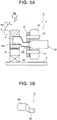
FIG. 3A is a front view of the spinning apparatus, and illustrates a diameter reducing process of the spinning method according to the first example embodiment of the invention; -
FIG. 3B is a perspective view of a target shape of the work in the diameter reducing process of the spinning method according to the first example embodiment of the invention, and illustrates this diameter reducing process; -
FIG. 4 is a front sectional view of the specific structure of the spinning head of the spinning apparatus according to the first example embodiment of the invention; -
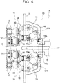
FIG. 5 is a front sectional view of the specific structure of a spinning head of a spinning apparatus according to a second example embodiment of the invention; -
FIG. 6A is a front view of a modified example of a core bar of a spinning apparatus according to a third example embodiment of the invention; -
FIG. 6B is a front view of a modified example of the core bar of the spinning apparatus according to the third example embodiment of the invention; and -
FIG. 6C is a modified example of the core bar of the spinning apparatus according to the third example embodiment of the invention. - Hereinafter, example embodiments of the invention will be described.
-
FIGS. 1A to 4 are views of a first example embodiment of the invention.FIG. 1A is a sectional view of a roller and the like taken along line IA - IA inFIG. 1B . Aspinning apparatus 1 according to the first example embodiment includes a table 2 that is arranged horizontally, as shown inFIG. 1A . Awork support base 3 that serves as a work supporting portion is attached onto the table 2 in such a manner as to be able to move in three axis directions (i.e., an X direction, a Y direction, and a Z direction), as well as swing around an axis in the X direction (i.e., in a RX direction), around an axis in the Y direction (i.e., in a RY direction), and around an axis in the Z direction (i.e., in a RZ direction), while supporting acylindrical work 4. Thiswork support base 3 is formed by abase 5 and achuck 6. That is, thebase 5 is supported so as to be able to move in three axis directions (i.e., the X direction, the Y direction, and the Z direction), on the table 2. Thechuck 6 that is able to grip thework 4 is mounted onto thebase 5 so as to be able to swing around an axis in the X direction (i.e., the RX direction), an axis in the Y direction (i.e., the RY direction), and an axis in the Z direction (i.e., the RZ direction). - Also, a spinning
head 7 is arranged near (to the right inFIG. 1A ) thework support base 3. The spinninghead 7 is formed by a spindle base, not shown, aspindle 10, threesupport shafts 11, and threerollers 12 and the like (seeFIG. 1B ). - That is, the spindle base, not shown, is provided upright on the table 2. The
annular spindle 10 is supported, in a manner so as to be able to rotate about a rotational axis CT1 by driving means, not shown, in a position facing thechuck 6, as shown inFIG. 1A , on a side surface of the spindle base. Together with thespindle 10, the threesupport shafts 11 are arranged at equiangular intervals (i.e., 120° intervals) on a circumference of a circle C1 that is centered around the rotational axis CT1, as shown inFIG. 1B . Thesesupport shafts 11 are configured so as to be able to move in the radial direction of thespindle 10. Therollers 12 are supported, in a manner so as to be able to rotate about axes CT2 of thesupport shafts 11, on thesupport shafts 11. - Furthermore, a generally pencil-shaped core bar (a mandrel) 13 of which an axis CT4 is positioned on the rotational axis CT1 of the
spindle 10, i.e., the axis of revolution of therollers 12, is attached to thespindle 10 in a manner so as to be able to advance and retreat in the direction of the rotational axis CT1 of the spindle 10 (i.e., the left-right direction inFIG. 1A ). Thiscore bar 13 has a circular cylindrical-shaped core barmain body 13a, and atip end portion 13b that is connected consecutively to one end of this core barmain body 13a. A diameter of the core barmain body 13a is formed to be substantially the same size as an inside diameter of thework 4. Therefore, the core barmain body 13a is shaped so that it fits inside a processedportion 4b of thework 4. - More specifically, the spinning
head 7 is such that thespindle 10 is formed by ahousing 16 and afaceplate 17, and thesupport shafts 11 are formed bysliders 18 androller holders 20, as shown inFIG. 4 . - That is, this spinning
head 7 has amain shaft 15 that is supported horizontally, as shown inFIG. 4 . Thehousing 16 is attached to themain shaft 15 in a manner so as to be able to rotate about an axis CT7 of themain shaft 15. Theannular faceplate 17 is fixed to thehousing 16 such that a surface of thefaceplate 17 is perpendicular to the axis CT7 of themain shaft 15, and the center of thefaceplate 17 is aligned with the axis CT7. The threesliders 18 are arranged on thefaceplate 17 at equiangular intervals (i.e., 120° intervals) on the circumference of a circle that is centered around the center of thefaceplate 17, i.e., the axis CT7 of themain shaft 15. Each of thesliders 18 is configured to be able to move in the radial direction of thefaceplate 17 by pivoting a boomerang-shapedslide ring 19 with driving means, not shown, as indicated by the solid lines and alternate long and two short dashes lines inFIG. 4 . That is, each of the slide rings 19 is supported in a manner so as to be able to rotate about a predetermined rotational axis CT8. Theslider 18 is connected to oneend 19a of theslide ring 19, and the driving means is connected to theother end 19b of theslide ring 19. Theslider 18 is then able to be moved in the radial direction of thefaceplate 17 by moving theother end 19b of theslide ring 19 in the horizontal direction using the driving means. Also, oneroller holder 20 is fixed to eachslider 18. Oneroller 12 is rotatably supported by eachroller holder 20. Moreover, thecore bar 13 is attached to themain shaft 15 in a manner so as to be able to advance and retreat in the direction of the axis CT7 of the main shaft 15 (i.e., in the left-right direction inFIG. 4 ). - The
spinning apparatus 1 is configured as described above, so the procedure for performing spinning on thework 4 that is cylindrical as shown inFIG. 1C using thisspinning apparatus 1 is as described below. - First, in a work preparation process, a supported
portion 4a of thework 4 is gripped by thechuck 6 of thework support base 3, as shown inFIG. 1A , while the threesupport shafts 11 are farthest away from the rotational axis CT1 of thespindle 10 in the radial direction of thespindle 10, and thecore bar 13 is retreated to the spinninghead 7 side. As a result, thework 4 is in a state supported horizontally with an axis CT3 thereof aligned with the rotational axis CT1 of thespindle 10. - Next, a core bar insertion process is performed. In this process, the
core bar 13 is advanced toward thework support base 3 side with respect to thework 4. Accordingly, thecore bar 13 is inserted inside of the processedportion 4b of thework 4. As a result, thecore bar 13 fits into the processedportion 4b of thework 4, just as described above, so the outer peripheral surface of the core barmain body 13a contacts the entire inner peripheral surface of the processedportion 4b of thework 4. - Then a roller contact process is performed. In this process, the three
support shafts 11 are moved toward the rotational axis CT1 of thespindle 10 in the radial direction of thespindle 10. As a result, the threerollers 12 contact the outer peripheral surface of thework 4. At this time, the threesupport shafts 11 are arranged at equiangular intervals on the circumference of the circle C1 that is centered around the rotational axis CT1 of thespindle 10, just as described above. Therefore, the threerollers 12 are also arranged at equiangular intervals around thework 4. - Continuing on, an offsetting process is performed. In this process, the
spindle 10 is rotated about the rotational axis CT1. As a result, the threerollers 12 revolve at a predetermined rotation rate with the rotational axis CT1 as the center of rotation, and thecore bar 13 synchronously spins at the same rotation rate with the rotational axis CT1 as the center of rotation. As a result, therollers 12 revolve around thework 4 while spinning with respect to the outer peripheral surface of the processedportion 4b of thework 4. Also, thecore bar 13 spins while contacting the inner peripheral surface of the processedportion 4b of thework 4. - In this state, the
work support base 3 is moved upward in the Z direction, as shown inFIG. 2A . As a result, the supportedportion 4a of thework 4 rises (i.e., moves upward) while the processedportion 4b of thework 4 remains in the original position. Therefore, an offsetting process in which a tube axis CT5 of the supportedportion 4a is offset upwards from a tube axis CT6 of the processedportion 4b is performed. As a result, forming beyond the outer shape of thework 4 is able to be performed, as shown inFIG. 2B . - At this time, the outer peripheral surface of the core bar
main body 13a of thecore bar 13 is contacting the entire inner peripheral surface of the processedportion 4b of thework 4, just as described above. Therefore, the work is able to be formed while maintaining the sectional shape (circular shape) of the processedportion 4b of thework 4. - Finally, a diameter reducing process is performed. In this process, the three
rollers 12 are moved toward the center in the radial direction of thespindle 10, and thework support base 3 is moved away from the spinninghead 7 in the X direction, as shown inFIG. 3A . As a result, the processedportion 4b of thework 4 is reduced in diameter by therollers 12, as shown inFIG. 3B . At this time, thecore bar 13 comes out from the processedportion 4b of thework 4 as thework support base 3 moves. Therefore, the process of reducing the diameter of the processedportion 4b of thework 4 is able to be performed smoothly. - With this, the spinning process performed on the
work 4 ends. - In this way, in the spinning process on the
cylindrical work 4, forming beyond the outer shape of thework 4 is made possible by moving thecore bar 13 that is inserted into the processedportion 4b of thework 4 and performing the offsetting process. - Also, the relative position of the
core bar 13 and a revolving surface of theroller 12 on the axis of revolution of therollers 12 is able to be moved. Therefore, various forming is able to be continuously performed on thework 4 when the spinning process is performed on thework 4, so productivity improves. - Furthermore, the
work support base 3 is able to swing around the axis in the X direction (i.e., the RX direction), the axis in the Y direction (i.e., the RY direction), and the axis in the Z direction (i.e., the RZ direction), just as described above. When spinning thework 4, thework support base 3 is swung appropriately according to the processing shape of the processedportion 4b of thework 4, while the supportedportion 4a of thework 4 is supported by thework support base 3. Accordingly, the tube axis CT6 of the processedportion 4b of thework 4 is also able to be inclined with respect to the tube axis CT5 of the supportedportion 4a of thework 4. As a result, it becomes possible to suitably bend thework 4 in a three-dimensional direction. -
FIG. 5 is a view of a second example embodiment of the invention. The spinninghead 7 of thespinning apparatus 1 according to the second example embodiment has a structure similar to that in the first example embodiment described above, except for that tworollers 12 are installed on each of the support shafts 11 (i.e., roller holders 20), as shown inFIG. 5 . Members in the second example embodiment that are the same as members in the first example embodiment will be denoted by like reference characters and descriptions of these members will be omitted. Also, the procedure of the spinning method of thework 4 is also the same as it is in the first example embodiment described above. - Therefore, this second example embodiment displays similar operation and effects as those displayed by the first example embodiment described above. In addition, in the spinning process on the work 4 (i.e., in the offsetting process and the diameter reducing process), the contact area between the
rollers 12 and thework 4 increases according to the increase in the number ofrollers 12. Therefore, the spinning process on thework 4 is able to be performed quickly and highly accurately. -
FIG. 6 is a view of a third example embodiment of the invention. In the first and second example embodiments described above, thespinning apparatus 1 provided with thecore bar 13 is described. The shape of thiscore bar 13 may be any shape suited to shaping thework 4 by spinning. - For example, a standard-
type core bar 13 in which a semisphericaltip end portion 13b is connected continuously to one end of a circular cylindrical core barmain body 13a may instead be used, as shown inFIG. 6A . This standard-type core bar 13 is suitable for use when the bending point of thework 4 is comparatively close. - Also, a long-
type core bar 13 in which thetip end portion 13b is shaped like half of a spheroid (a long spheroid) is connected continuously to one end of the circular cylindrical core barmain body 13a may instead be used, as shown inFIG. 6B . Using this long-type core bar 13 enables abeautiful work 4 with few irregularities on the outer peripheral surface to be obtained when the inner diameter after of thework 4 after the diameter reducing process is small and the area over which the inner diameter is changed in steps is large. - Moreover, a stepped-
type core bar 13 in which a small diameter circular cylindrical-shaped smalldiameter corresponding portion 13c is attached to an apex portion of thetip end portion 13b of a standard-type core bar 13, as shown inFIG. 6C . Using this stepped-type core bar 13 enables the smalldiameter corresponding portion 13c of thecore bar 13 to make contact from the inner peripheral surface of thework 4 and thus provide reaction force with respect to force that acts on the outer peripheral surface of thework 4 from therollers 12 when spinning thework 4, when high diameter dimensional accuracy is required at the formed end portion of the work 4 (for example, when a mating part is to fit with this formed end portion). As a result, the processing accuracy of thework 4 is able to be increased. - In the first to the third example embodiments described above, a spinning
head 7 configured such that thehousing 16 is rotatably attached to themain shaft 15 is described. However, a structure in which themain shaft 15 rotates together with thehousing 16 may also be employed. In this case, providing a lock-unlock switching mechanism, not shown, between themain shaft 15 and thecore bar 13 would make it possible to appropriately select between making thecore bar 13 follow the rotation of the main shaft 15 (when locked), and making thecore bar 13 not follow the rotation of the main shaft 15 (when unlocked), according to the type of processing of thework 4. This would make it possible to handle a variety of types of processing of thework 4. Also, in the first to the third example embodiments described above, a case is described in which an offsetting process is performed on thework 4 by moving thework support base 3 upward in the Z direction in the spinning process (i.e., the offsetting process) of thework 4. However, the offsetting process may also be performed on thework 4 by lowering the spinninghead 7 and moving the processedportion 4b of thework 4 downward while thecore bar 13 is inserted in the processedportion 4b of thework 4, instead of moving thework support base 3 upward in the Z direction. That is, the processedportion 4b of thework 4 need only be moved in the vertical direction relative to thework support base 3. Alternatively, the processedportion 4b of thework 4 may be moved in the left-right direction relative to thework support base 3 side. - Also, in the first to third example embodiments described above, a spinning
head 7 in which the threesupport shafts 11 are arranged at equiangular intervals (120° intervals) is described. However, the number ofsupport shafts 11 is not limited to three. Also, when there is a plurality ofsupport shafts 11, it is not absolutely necessary that they be arranged at equiangular intervals. - Further, in the first example embodiment described above, a spinning
head 7 in which oneroller 12 is installed on eachsupport shaft 11 is described, and in the second example embodiment described above, the spinninghead 7 in which tworollers 12 are installed on eachsupport shaft 11 is described. However, the number ofrollers 12 installed on eachsupport shaft 11 is not limited to one or two. That is, three ormore rollers 12 may also be installed on eachsupport shaft 11. - Also, in the first to the third example embodiments described above, a spinning
head 7 configured such that therollers 12 are rotatably supported by thesupport shafts 11, and theserollers 12 spin against the outer peripheral surface of thework 4 when spinning thework 4, is described. However, the structure may also be such that therollers 12 are fixed to thesupport shafts 11, and therollers 12 slide against the outer peripheral surface of thework 4 when spinning thework 4. - Further, in the first to the third example embodiments described above, a case in which an offsetting process is performed on the
work 4 when spinning thework 4, is described. However, the invention is not limited to this kind of offsetting process. That is, a forming process that points the tube axis CT6 of the processedportion 4b of thework 4 in a given direction may also be performed. This enables a variety of members having complex cylindrical shapes to be integrally formed from thecylindrical work 4. - Moreover, the processed
portion 4b of thework 4 may also be reduced in diameter by suitably reducing the revolution diameter of therollers 12 with the forming process to point the tube axis CT6 of the processedportion 4b of thework 4 in a given direction. In this case, the forming process to point the tube axis CT6 of the processedportion 4b of thework 4 in the given direction, and the diameter reducing process are performed simultaneously. As a result, productivity is able to be increased. - Also, in the first to the third example embodiments described above, a
spinning apparatus 1 provided with onecore bar 13 that has a shape enabling it to fit into the processedportion 4b of thework 4 is described. However, the shape and number of thecore bar 13 is not particularly limited as long as the processedportion 4b of thework 4 is able to move relative to thework support base 3 side. For example, a plurality (two or more) core bars 13 each having a diameter approximately 1/3 the inside diameter of thework 4 may be attached to thespindle 10 such that the axis of each of the core bars 13 is offset by an equal distance from the rotational axis CT1 of thespindle 10. At this time, performing control to maintain a positional relationship in which thecore bar 13 is always facing the inside of the rollers 12 (i.e., side where the axis of revolution of therollers 12 is located) across thework 4 enables thecore bar 13 to make contact from the inner peripheral surface of thework 4 and thus provide reaction force with respect to force that acts on the outer peripheral surface of thework 4 from therollers 12, when therollers 12 revolve in the spinning process on thework 4. As a result, the processing accuracy of thework 4 is able to be increased. - The invention is extremely useful when integrally forming a member having a three dimensionally complex cylindrical shape, more specifically, a surge tank, a separation tank of a turbocharger, a muffler for a two-wheel vehicle, a catalytic converter, a diesel exhaust treatment device (i.e., a diesel particulate filter), and various pressure containers and the like, from cylindrical material by spinning.
Claims (11)
- A spinning method comprising:supporting a supported portion of a cylindrical work by a work supporting portion (3);pressing a roller (12) of a spinning head against an outer peripheral surface of a processed portion of the work while revolving the roller;performing a forming process that points a tube axis of the processed portion of the work in a given direction by moving the processed portion relative to the work supporting portion or moving the work supporting portion relative to the processed portion in a direction perpendicular to a tube axis of the supported portion, while making a core bar (13) inserted into the processed portion of the work contact an inner peripheral surface of the processed portion,characterised in that the forming process further comprises, reducing a diameter of the processed portion of the work by appropriately reducing a revolution diameter of the roller and moving the work supporting portion away from the spinning head in a direction parallel to the tube axis of the supported portion, at this time the core bar comes out from the processed portion of the cylindrical work as the work supporting portion moves.
- The spinning method according to claim 1, further comprising:
performing an offsetting process in which the tube axis of the processed portion of the work is offset from a tube axis of the supported portion of the work by moving the processed portion of the work relative to the work supporting portion, by moving the work supporting portion or moving the processed portion. - The spinning method according to claim 2, wherein
the forming process includes inclining the tube axis of the processed portion of the work with respect to the tube axis of the supported portion of the work, by appropriately swinging the work supporting portion while the supported portion of the work is supported by the work supporting portion. - The spinning method according to claim 1, wherein
the forming process includes inclining the tube axis of the processed portion of the work with respect to a tube axis of the supported portion of the work, by appropriately swinging the work supporting portion while the supported portion of the work is supported by the work supporting portion. - The spinning method according to any one of claims 1 to 4, wherein
the core bar is formed in a shape that fits inside of the processed portion of the work. - The spinning method according to any one of claims 1 to 5, wherein
a relative position of the core bar and a revolving surface of the roller on an axis of revolution of the roller is able to be moved. - A spinning apparatus comprising:a work supporting portion (3) configured to support a supported portion of a cylindrical work;a plurality of rollers (12) of a spinning head configured to be pressed against an outer peripheral surface of a processed portion of the work while being revolved; anda core bar (13) provided, so as to be able to advance and retreat in a rotational axis direction of a spindle of the spinning head, in a position surrounded by the rollers, whereinthe plurality of rollers are provided at substantially equiangular intervals on a circumference of a circle that is centered around a rotational axis of the spindle;characterised in that the core bar is configured to be inserted in the processed portion of the work and contact an inner peripheral surface of the processed portion;the core bar is configured to move relative to the work supporting portion or the work supporting portion moves relative to the core bar while the core bar is contacting the inner peripheral surface of the processed portion; andthe work supporting portion is able to move in three axis directions: an X direction, a Y direction, and a Z direction,wherein the spinning apparatus is configured to reduce a diameter of the processed portion of the work by appropriately reducing a revolution diameter of the roller and moving the work supporting portion away from the spinning head in a direction parallel to the tube axis of the supported portion, and the core bar comes out from the processed portion of the cylindrical work as the work supporting portion moves..
- The spinning apparatus according to claim 7, wherein
the work supporting portion is configured such that an offsetting process, in which a tube axis of the processed portion of the work is offset from a tube axis of the supported portion of the work by the processed portion of the work being moved relative to the work supporting portion, is performed by the work supporting portion or the core bar being moved. - The spinning apparatus according to claim 8, wherein
the work supporting portion swings such that the tube axis of the processed portion of the work is inclined with respect to the tube axis of the supported portion of the work. - The spinning apparatus according to claim 7, wherein
the work supporting portion swings such that a tube axis of the processed portion of the work is inclined with respect to a tube axis of the supported portion of the work. - The spinning apparatus according to any one of claims 7 to 10, wherein
the core bar is formed in a shape that fits into the processed portion of the work.
Applications Claiming Priority (2)
| Application Number | Priority Date | Filing Date | Title |
|---|---|---|---|
| JP2013077844A JP6126439B2 (en) | 2013-04-03 | 2013-04-03 | Spinning processing method and spinning processing apparatus |
| PCT/IB2014/000537 WO2014162198A1 (en) | 2013-04-03 | 2014-04-01 | Spinning method and spinning apparatus |
Publications (2)
| Publication Number | Publication Date |
|---|---|
| EP2981370A1 EP2981370A1 (en) | 2016-02-10 |
| EP2981370B1 true EP2981370B1 (en) | 2020-12-23 |
Family
ID=50588759
Family Applications (1)
| Application Number | Title | Priority Date | Filing Date |
|---|---|---|---|
| EP14719857.6A Not-in-force EP2981370B1 (en) | 2013-04-03 | 2014-04-01 | Spinning method and spinning apparatus |
Country Status (5)
| Country | Link |
|---|---|
| US (1) | US10166582B2 (en) |
| EP (1) | EP2981370B1 (en) |
| JP (1) | JP6126439B2 (en) |
| CN (1) | CN105307791B (en) |
| WO (1) | WO2014162198A1 (en) |
Families Citing this family (3)
| Publication number | Priority date | Publication date | Assignee | Title |
|---|---|---|---|---|
| DE102018112295A1 (en) * | 2018-05-23 | 2019-11-28 | Federal-Mogul Valvetrain Gmbh | METHOD FOR PRODUCING A HOLLOW VALVE WITH OPTIMIZED SHAFT INNER GEOMETRY FOR COMBUSTION ENGINES |
| CN110587234A (en) * | 2019-09-12 | 2019-12-20 | 宁波金田铜管有限公司 | Processing technology of reducing pipe fitting |
| CN111633078B (en) * | 2020-06-17 | 2021-05-25 | 南京航空航天大学 | Ultra-thin wall bent pipe rotary bending forming method and device |
Family Cites Families (25)
| Publication number | Priority date | Publication date | Assignee | Title |
|---|---|---|---|---|
| DE2457504C3 (en) * | 1974-12-05 | 1983-04-21 | Messerschmitt-Bölkow-Blohm GmbH, 8000 München | Extrusion process and machine |
| JPS6036326B2 (en) * | 1980-12-29 | 1985-08-20 | 三菱マテリアル株式会社 | Metal tube inner and outer surface processing equipment |
| US6018972A (en) * | 1997-11-11 | 2000-02-01 | Sango Co., Ltd | Method and apparatus for forming an end portion of a cylindrical member |
| JP2922201B1 (en) * | 1998-07-21 | 1999-07-19 | 株式会社三五 | Spinning method and its equipment |
| JP3578320B2 (en) | 1999-03-02 | 2004-10-20 | トヨタ自動車株式会社 | Tube forming method |
| US6233993B1 (en) * | 1999-05-10 | 2001-05-22 | Sango Co., Ltd. | Method and apparatus for forming a processed portion of a workpiece |
| JP3390725B2 (en) * | 1999-05-10 | 2003-03-31 | 株式会社三五 | Method and apparatus for forming work of different diameter |
| US6381843B1 (en) * | 1999-08-03 | 2002-05-07 | Sango Co., Ltd. | Method of producing a catalytic converter |
| US6591498B2 (en) * | 1999-08-03 | 2003-07-15 | Sango Co., Ltd. | Method of producing a catalytic converter |
| NL1016348C2 (en) | 2000-07-21 | 2002-01-22 | Johan Massue | Method and forming machine for deforming a hollow workpiece. |
| JP2002172429A (en) * | 2000-12-01 | 2002-06-18 | Nippon Spindle Mfg Co Ltd | Method and apparatus for forming cylindrically shaped material to be processed |
| JP2002316218A (en) * | 2001-04-18 | 2002-10-29 | Sango Co Ltd | Spindle mechanism |
| US6442988B1 (en) | 2001-05-01 | 2002-09-03 | Alcan International Limited | Methods of spin forming initially cylindrical containers and the like |
| JP2003010935A (en) * | 2001-06-29 | 2003-01-15 | Toyota Motor Corp | Hollow member, manufacturing method thereof, manufacturing apparatus thereof, and fluid distribution system using the hollow member |
| JP4003056B2 (en) | 2001-10-09 | 2007-11-07 | トヨタ自動車株式会社 | Spinning molding method and spinning molding apparatus |
| NL1020171C2 (en) | 2002-03-13 | 2003-09-16 | Johan Massee | Method and forming machine for machining a workpiece. |
| JP2005000930A (en) * | 2003-06-10 | 2005-01-06 | Toyota Motor Corp | Spinning processing apparatus, spinning processing method, and catalytic converter manufactured using the same |
| US6990841B2 (en) * | 2003-10-17 | 2006-01-31 | Delphi Technologies, Inc. | Method and apparatus for lean spin forming transition portions having various shapes |
| JP5143338B2 (en) * | 2004-12-27 | 2013-02-13 | 株式会社三五 | Method and apparatus for forming different diameter parts of workpiece |
| JP4393470B2 (en) * | 2006-04-14 | 2010-01-06 | 日本スピンドル製造株式会社 | Drawing method and apparatus |
| JP5435190B2 (en) * | 2007-03-30 | 2014-03-05 | 日立オートモティブシステムズ株式会社 | Tube processing method and cylinder device manufacturing method |
| JP4485579B2 (en) * | 2008-02-06 | 2010-06-23 | 日本スピンドル製造株式会社 | Drawing method for non-circular cylindrical work material |
| JP5339513B2 (en) * | 2009-01-23 | 2013-11-13 | 日新製鋼株式会社 | Spinning method |
| CN101954401B (en) * | 2010-01-07 | 2012-03-28 | 浙江格洛斯无缝钢管有限公司 | Power spinning new method for seamless tube |
| EP2353744A1 (en) * | 2010-02-02 | 2011-08-10 | Repkon Machine and Tool Industry & Trade Ltd. | Method for shaping a rotationally symmetric hollow body and device for executing the method |
-
2013
- 2013-04-03 JP JP2013077844A patent/JP6126439B2/en active Active
-
2014
- 2014-04-01 WO PCT/IB2014/000537 patent/WO2014162198A1/en not_active Ceased
- 2014-04-01 CN CN201480019452.2A patent/CN105307791B/en not_active Expired - Fee Related
- 2014-04-01 US US14/781,816 patent/US10166582B2/en not_active Expired - Fee Related
- 2014-04-01 EP EP14719857.6A patent/EP2981370B1/en not_active Not-in-force
Non-Patent Citations (1)
| Title |
|---|
| None * |
Also Published As
| Publication number | Publication date |
|---|---|
| JP6126439B2 (en) | 2017-05-10 |
| CN105307791A (en) | 2016-02-03 |
| JP2014200808A (en) | 2014-10-27 |
| US10166582B2 (en) | 2019-01-01 |
| US20160059286A1 (en) | 2016-03-03 |
| CN105307791B (en) | 2019-08-06 |
| WO2014162198A1 (en) | 2014-10-09 |
| EP2981370A1 (en) | 2016-02-10 |
Similar Documents
| Publication | Publication Date | Title |
|---|---|---|
| US11305327B2 (en) | Spinning method and spinning apparatus | |
| EP1017515B1 (en) | Spinning processing method and apparatus therefor | |
| JP2005525937A5 (en) | ||
| US8091396B2 (en) | Method for forming an end portion of a cylindrical workpiece | |
| US10166582B2 (en) | Spinning method and spinning apparatus | |
| CN103715842A (en) | Winding apparatus | |
| JP4647056B2 (en) | Tube forming method and forming apparatus | |
| JPH11147138A (en) | Forming method for pipe end and device for the same | |
| US7021107B2 (en) | Bending processor of pipe | |
| KR20110037577A (en) | Hybrid terminal manufacturing equipment | |
| CN107838262B (en) | A dieless spinning forming method for non-axisymmetric thin-walled shell parts | |
| JP5389522B2 (en) | Coil forming method and coil forming apparatus | |
| NL1017010C2 (en) | Method and device for deforming a hollow workpiece. | |
| JP2017144457A (en) | Molding device and molding method | |
| JP2005000930A (en) | Spinning processing apparatus, spinning processing method, and catalytic converter manufactured using the same | |
| JP6062007B2 (en) | Spinning processing method and spinning processing apparatus | |
| JP2010240715A (en) | Bending device | |
| JP5942826B2 (en) | Molding apparatus and molding method | |
| US8864552B2 (en) | Camshaft-grinding machine | |
| CN106944582B (en) | Robot automatic loading/unloading bolt rolls system and bolt rolling depression method | |
| JP4822928B2 (en) | Molding method and molding apparatus | |
| JP2008036676A (en) | Bending apparatus | |
| CN105215101B (en) | A kind of pipe fitting bends continuous processing equipment | |
| JP2007125579A (en) | Forming method and forming apparatus | |
| JP2014147953A (en) | Forming method and forming apparatus |
Legal Events
| Date | Code | Title | Description |
|---|---|---|---|
| PUAI | Public reference made under article 153(3) epc to a published international application that has entered the european phase |
Free format text: ORIGINAL CODE: 0009012 |
|
| 17P | Request for examination filed |
Effective date: 20151003 |
|
| AK | Designated contracting states |
Kind code of ref document: A1 Designated state(s): AL AT BE BG CH CY CZ DE DK EE ES FI FR GB GR HR HU IE IS IT LI LT LU LV MC MK MT NL NO PL PT RO RS SE SI SK SM TR |
|
| AX | Request for extension of the european patent |
Extension state: BA ME |
|
| RAP1 | Party data changed (applicant data changed or rights of an application transferred) |
Owner name: TOYOTA JIDOSHA KABUSHIKI KAISHA |
|
| DAX | Request for extension of the european patent (deleted) | ||
| STAA | Information on the status of an ep patent application or granted ep patent |
Free format text: STATUS: EXAMINATION IS IN PROGRESS |
|
| 17Q | First examination report despatched |
Effective date: 20170503 |
|
| TPAC | Observations filed by third parties |
Free format text: ORIGINAL CODE: EPIDOSNTIPA |
|
| TPAC | Observations filed by third parties |
Free format text: ORIGINAL CODE: EPIDOSNTIPA |
|
| GRAP | Despatch of communication of intention to grant a patent |
Free format text: ORIGINAL CODE: EPIDOSNIGR1 |
|
| STAA | Information on the status of an ep patent application or granted ep patent |
Free format text: STATUS: GRANT OF PATENT IS INTENDED |
|
| INTG | Intention to grant announced |
Effective date: 20200720 |
|
| GRAS | Grant fee paid |
Free format text: ORIGINAL CODE: EPIDOSNIGR3 |
|
| GRAA | (expected) grant |
Free format text: ORIGINAL CODE: 0009210 |
|
| STAA | Information on the status of an ep patent application or granted ep patent |
Free format text: STATUS: THE PATENT HAS BEEN GRANTED |
|
| AK | Designated contracting states |
Kind code of ref document: B1 Designated state(s): AL AT BE BG CH CY CZ DE DK EE ES FI FR GB GR HR HU IE IS IT LI LT LU LV MC MK MT NL NO PL PT RO RS SE SI SK SM TR |
|
| REG | Reference to a national code |
Ref country code: GB Ref legal event code: FG4D |
|
| REG | Reference to a national code |
Ref country code: DE Ref legal event code: R096 Ref document number: 602014073558 Country of ref document: DE |
|
| REG | Reference to a national code |
Ref country code: AT Ref legal event code: REF Ref document number: 1347239 Country of ref document: AT Kind code of ref document: T Effective date: 20210115 |
|
| REG | Reference to a national code |
Ref country code: IE Ref legal event code: FG4D |
|
| PG25 | Lapsed in a contracting state [announced via postgrant information from national office to epo] |
Ref country code: GR Free format text: LAPSE BECAUSE OF FAILURE TO SUBMIT A TRANSLATION OF THE DESCRIPTION OR TO PAY THE FEE WITHIN THE PRESCRIBED TIME-LIMIT Effective date: 20210324 Ref country code: FI Free format text: LAPSE BECAUSE OF FAILURE TO SUBMIT A TRANSLATION OF THE DESCRIPTION OR TO PAY THE FEE WITHIN THE PRESCRIBED TIME-LIMIT Effective date: 20201223 Ref country code: RS Free format text: LAPSE BECAUSE OF FAILURE TO SUBMIT A TRANSLATION OF THE DESCRIPTION OR TO PAY THE FEE WITHIN THE PRESCRIBED TIME-LIMIT Effective date: 20201223 Ref country code: NO Free format text: LAPSE BECAUSE OF FAILURE TO SUBMIT A TRANSLATION OF THE DESCRIPTION OR TO PAY THE FEE WITHIN THE PRESCRIBED TIME-LIMIT Effective date: 20210323 |
|
| REG | Reference to a national code |
Ref country code: AT Ref legal event code: MK05 Ref document number: 1347239 Country of ref document: AT Kind code of ref document: T Effective date: 20201223 |
|
| REG | Reference to a national code |
Ref country code: NL Ref legal event code: MP Effective date: 20201223 |
|
| PG25 | Lapsed in a contracting state [announced via postgrant information from national office to epo] |
Ref country code: BG Free format text: LAPSE BECAUSE OF FAILURE TO SUBMIT A TRANSLATION OF THE DESCRIPTION OR TO PAY THE FEE WITHIN THE PRESCRIBED TIME-LIMIT Effective date: 20210323 Ref country code: LV Free format text: LAPSE BECAUSE OF FAILURE TO SUBMIT A TRANSLATION OF THE DESCRIPTION OR TO PAY THE FEE WITHIN THE PRESCRIBED TIME-LIMIT Effective date: 20201223 Ref country code: SE Free format text: LAPSE BECAUSE OF FAILURE TO SUBMIT A TRANSLATION OF THE DESCRIPTION OR TO PAY THE FEE WITHIN THE PRESCRIBED TIME-LIMIT Effective date: 20201223 |
|
| PG25 | Lapsed in a contracting state [announced via postgrant information from national office to epo] |
Ref country code: NL Free format text: LAPSE BECAUSE OF FAILURE TO SUBMIT A TRANSLATION OF THE DESCRIPTION OR TO PAY THE FEE WITHIN THE PRESCRIBED TIME-LIMIT Effective date: 20201223 Ref country code: HR Free format text: LAPSE BECAUSE OF FAILURE TO SUBMIT A TRANSLATION OF THE DESCRIPTION OR TO PAY THE FEE WITHIN THE PRESCRIBED TIME-LIMIT Effective date: 20201223 |
|
| REG | Reference to a national code |
Ref country code: LT Ref legal event code: MG9D |
|
| PG25 | Lapsed in a contracting state [announced via postgrant information from national office to epo] |
Ref country code: SK Free format text: LAPSE BECAUSE OF FAILURE TO SUBMIT A TRANSLATION OF THE DESCRIPTION OR TO PAY THE FEE WITHIN THE PRESCRIBED TIME-LIMIT Effective date: 20201223 Ref country code: PT Free format text: LAPSE BECAUSE OF FAILURE TO SUBMIT A TRANSLATION OF THE DESCRIPTION OR TO PAY THE FEE WITHIN THE PRESCRIBED TIME-LIMIT Effective date: 20210423 Ref country code: RO Free format text: LAPSE BECAUSE OF FAILURE TO SUBMIT A TRANSLATION OF THE DESCRIPTION OR TO PAY THE FEE WITHIN THE PRESCRIBED TIME-LIMIT Effective date: 20201223 Ref country code: LT Free format text: LAPSE BECAUSE OF FAILURE TO SUBMIT A TRANSLATION OF THE DESCRIPTION OR TO PAY THE FEE WITHIN THE PRESCRIBED TIME-LIMIT Effective date: 20201223 Ref country code: SM Free format text: LAPSE BECAUSE OF FAILURE TO SUBMIT A TRANSLATION OF THE DESCRIPTION OR TO PAY THE FEE WITHIN THE PRESCRIBED TIME-LIMIT Effective date: 20201223 Ref country code: CZ Free format text: LAPSE BECAUSE OF FAILURE TO SUBMIT A TRANSLATION OF THE DESCRIPTION OR TO PAY THE FEE WITHIN THE PRESCRIBED TIME-LIMIT Effective date: 20201223 Ref country code: EE Free format text: LAPSE BECAUSE OF FAILURE TO SUBMIT A TRANSLATION OF THE DESCRIPTION OR TO PAY THE FEE WITHIN THE PRESCRIBED TIME-LIMIT Effective date: 20201223 |
|
| PGFP | Annual fee paid to national office [announced via postgrant information from national office to epo] |
Ref country code: DE Payment date: 20210316 Year of fee payment: 8 |
|
| PG25 | Lapsed in a contracting state [announced via postgrant information from national office to epo] |
Ref country code: PL Free format text: LAPSE BECAUSE OF FAILURE TO SUBMIT A TRANSLATION OF THE DESCRIPTION OR TO PAY THE FEE WITHIN THE PRESCRIBED TIME-LIMIT Effective date: 20201223 Ref country code: AT Free format text: LAPSE BECAUSE OF FAILURE TO SUBMIT A TRANSLATION OF THE DESCRIPTION OR TO PAY THE FEE WITHIN THE PRESCRIBED TIME-LIMIT Effective date: 20201223 |
|
| REG | Reference to a national code |
Ref country code: DE Ref legal event code: R097 Ref document number: 602014073558 Country of ref document: DE |
|
| PG25 | Lapsed in a contracting state [announced via postgrant information from national office to epo] |
Ref country code: IS Free format text: LAPSE BECAUSE OF FAILURE TO SUBMIT A TRANSLATION OF THE DESCRIPTION OR TO PAY THE FEE WITHIN THE PRESCRIBED TIME-LIMIT Effective date: 20210423 |
|
| PG25 | Lapsed in a contracting state [announced via postgrant information from national office to epo] |
Ref country code: AL Free format text: LAPSE BECAUSE OF FAILURE TO SUBMIT A TRANSLATION OF THE DESCRIPTION OR TO PAY THE FEE WITHIN THE PRESCRIBED TIME-LIMIT Effective date: 20201223 Ref country code: IT Free format text: LAPSE BECAUSE OF FAILURE TO SUBMIT A TRANSLATION OF THE DESCRIPTION OR TO PAY THE FEE WITHIN THE PRESCRIBED TIME-LIMIT Effective date: 20201223 |
|
| PLBE | No opposition filed within time limit |
Free format text: ORIGINAL CODE: 0009261 |
|
| STAA | Information on the status of an ep patent application or granted ep patent |
Free format text: STATUS: NO OPPOSITION FILED WITHIN TIME LIMIT |
|
| PG25 | Lapsed in a contracting state [announced via postgrant information from national office to epo] |
Ref country code: ES Free format text: LAPSE BECAUSE OF FAILURE TO SUBMIT A TRANSLATION OF THE DESCRIPTION OR TO PAY THE FEE WITHIN THE PRESCRIBED TIME-LIMIT Effective date: 20201223 Ref country code: DK Free format text: LAPSE BECAUSE OF FAILURE TO SUBMIT A TRANSLATION OF THE DESCRIPTION OR TO PAY THE FEE WITHIN THE PRESCRIBED TIME-LIMIT Effective date: 20201223 Ref country code: MC Free format text: LAPSE BECAUSE OF FAILURE TO SUBMIT A TRANSLATION OF THE DESCRIPTION OR TO PAY THE FEE WITHIN THE PRESCRIBED TIME-LIMIT Effective date: 20201223 |
|
| 26N | No opposition filed |
Effective date: 20210924 |
|
| GBPC | Gb: european patent ceased through non-payment of renewal fee |
Effective date: 20210401 |
|
| PG25 | Lapsed in a contracting state [announced via postgrant information from national office to epo] |
Ref country code: LU Free format text: LAPSE BECAUSE OF NON-PAYMENT OF DUE FEES Effective date: 20210401 |
|
| REG | Reference to a national code |
Ref country code: BE Ref legal event code: MM Effective date: 20210430 |
|
| PG25 | Lapsed in a contracting state [announced via postgrant information from national office to epo] |
Ref country code: LI Free format text: LAPSE BECAUSE OF NON-PAYMENT OF DUE FEES Effective date: 20210430 Ref country code: CH Free format text: LAPSE BECAUSE OF NON-PAYMENT OF DUE FEES Effective date: 20210430 Ref country code: GB Free format text: LAPSE BECAUSE OF NON-PAYMENT OF DUE FEES Effective date: 20210401 Ref country code: FR Free format text: LAPSE BECAUSE OF NON-PAYMENT OF DUE FEES Effective date: 20210430 |
|
| PG25 | Lapsed in a contracting state [announced via postgrant information from national office to epo] |
Ref country code: SI Free format text: LAPSE BECAUSE OF FAILURE TO SUBMIT A TRANSLATION OF THE DESCRIPTION OR TO PAY THE FEE WITHIN THE PRESCRIBED TIME-LIMIT Effective date: 20201223 |
|
| PG25 | Lapsed in a contracting state [announced via postgrant information from national office to epo] |
Ref country code: IE Free format text: LAPSE BECAUSE OF NON-PAYMENT OF DUE FEES Effective date: 20210401 |
|
| PG25 | Lapsed in a contracting state [announced via postgrant information from national office to epo] |
Ref country code: IS Free format text: LAPSE BECAUSE OF FAILURE TO SUBMIT A TRANSLATION OF THE DESCRIPTION OR TO PAY THE FEE WITHIN THE PRESCRIBED TIME-LIMIT Effective date: 20210423 |
|
| PG25 | Lapsed in a contracting state [announced via postgrant information from national office to epo] |
Ref country code: BE Free format text: LAPSE BECAUSE OF NON-PAYMENT OF DUE FEES Effective date: 20210430 |
|
| REG | Reference to a national code |
Ref country code: DE Ref legal event code: R119 Ref document number: 602014073558 Country of ref document: DE |
|
| PG25 | Lapsed in a contracting state [announced via postgrant information from national office to epo] |
Ref country code: DE Free format text: LAPSE BECAUSE OF NON-PAYMENT OF DUE FEES Effective date: 20221103 |
|
| PG25 | Lapsed in a contracting state [announced via postgrant information from national office to epo] |
Ref country code: HU Free format text: LAPSE BECAUSE OF FAILURE TO SUBMIT A TRANSLATION OF THE DESCRIPTION OR TO PAY THE FEE WITHIN THE PRESCRIBED TIME-LIMIT; INVALID AB INITIO Effective date: 20140401 |
|
| PG25 | Lapsed in a contracting state [announced via postgrant information from national office to epo] |
Ref country code: CY Free format text: LAPSE BECAUSE OF FAILURE TO SUBMIT A TRANSLATION OF THE DESCRIPTION OR TO PAY THE FEE WITHIN THE PRESCRIBED TIME-LIMIT Effective date: 20201223 |
|
| PG25 | Lapsed in a contracting state [announced via postgrant information from national office to epo] |
Ref country code: MK Free format text: LAPSE BECAUSE OF FAILURE TO SUBMIT A TRANSLATION OF THE DESCRIPTION OR TO PAY THE FEE WITHIN THE PRESCRIBED TIME-LIMIT Effective date: 20201223 |
|
| PG25 | Lapsed in a contracting state [announced via postgrant information from national office to epo] |
Ref country code: MT Free format text: LAPSE BECAUSE OF FAILURE TO SUBMIT A TRANSLATION OF THE DESCRIPTION OR TO PAY THE FEE WITHIN THE PRESCRIBED TIME-LIMIT Effective date: 20201223 |
|
| PG25 | Lapsed in a contracting state [announced via postgrant information from national office to epo] |
Ref country code: TR Free format text: LAPSE BECAUSE OF FAILURE TO SUBMIT A TRANSLATION OF THE DESCRIPTION OR TO PAY THE FEE WITHIN THE PRESCRIBED TIME-LIMIT Effective date: 20201223 |