EP2980955A1 - Vehicle power unit - Google Patents
Vehicle power unit Download PDFInfo
- Publication number
- EP2980955A1 EP2980955A1 EP14774000.5A EP14774000A EP2980955A1 EP 2980955 A1 EP2980955 A1 EP 2980955A1 EP 14774000 A EP14774000 A EP 14774000A EP 2980955 A1 EP2980955 A1 EP 2980955A1
- Authority
- EP
- European Patent Office
- Prior art keywords
- power
- power conversion
- threshold
- conversion circuit
- connector
- Prior art date
- Legal status (The legal status is an assumption and is not a legal conclusion. Google has not performed a legal analysis and makes no representation as to the accuracy of the status listed.)
- Withdrawn
Links
Images


Classifications
-
- B—PERFORMING OPERATIONS; TRANSPORTING
- B60—VEHICLES IN GENERAL
- B60L—PROPULSION OF ELECTRICALLY-PROPELLED VEHICLES; SUPPLYING ELECTRIC POWER FOR AUXILIARY EQUIPMENT OF ELECTRICALLY-PROPELLED VEHICLES; ELECTRODYNAMIC BRAKE SYSTEMS FOR VEHICLES IN GENERAL; MAGNETIC SUSPENSION OR LEVITATION FOR VEHICLES; MONITORING OPERATING VARIABLES OF ELECTRICALLY-PROPELLED VEHICLES; ELECTRIC SAFETY DEVICES FOR ELECTRICALLY-PROPELLED VEHICLES
- B60L3/00—Electric devices on electrically-propelled vehicles for safety purposes; Monitoring operating variables, e.g. speed, deceleration or energy consumption
- B60L3/0023—Detecting, eliminating, remedying or compensating for drive train abnormalities, e.g. failures within the drive train
- B60L3/003—Detecting, eliminating, remedying or compensating for drive train abnormalities, e.g. failures within the drive train relating to inverters
-
- B—PERFORMING OPERATIONS; TRANSPORTING
- B60—VEHICLES IN GENERAL
- B60L—PROPULSION OF ELECTRICALLY-PROPELLED VEHICLES; SUPPLYING ELECTRIC POWER FOR AUXILIARY EQUIPMENT OF ELECTRICALLY-PROPELLED VEHICLES; ELECTRODYNAMIC BRAKE SYSTEMS FOR VEHICLES IN GENERAL; MAGNETIC SUSPENSION OR LEVITATION FOR VEHICLES; MONITORING OPERATING VARIABLES OF ELECTRICALLY-PROPELLED VEHICLES; ELECTRIC SAFETY DEVICES FOR ELECTRICALLY-PROPELLED VEHICLES
- B60L3/00—Electric devices on electrically-propelled vehicles for safety purposes; Monitoring operating variables, e.g. speed, deceleration or energy consumption
- B60L3/04—Cutting off the power supply under fault conditions
-
- B—PERFORMING OPERATIONS; TRANSPORTING
- B60—VEHICLES IN GENERAL
- B60L—PROPULSION OF ELECTRICALLY-PROPELLED VEHICLES; SUPPLYING ELECTRIC POWER FOR AUXILIARY EQUIPMENT OF ELECTRICALLY-PROPELLED VEHICLES; ELECTRODYNAMIC BRAKE SYSTEMS FOR VEHICLES IN GENERAL; MAGNETIC SUSPENSION OR LEVITATION FOR VEHICLES; MONITORING OPERATING VARIABLES OF ELECTRICALLY-PROPELLED VEHICLES; ELECTRIC SAFETY DEVICES FOR ELECTRICALLY-PROPELLED VEHICLES
- B60L53/00—Methods of charging batteries, specially adapted for electric vehicles; Charging stations or on-board charging equipment therefor; Exchange of energy storage elements in electric vehicles
- B60L53/10—Methods of charging batteries, specially adapted for electric vehicles; Charging stations or on-board charging equipment therefor; Exchange of energy storage elements in electric vehicles characterised by the energy transfer between the charging station and the vehicle
- B60L53/14—Conductive energy transfer
- B60L53/16—Connectors, e.g. plugs or sockets, specially adapted for charging electric vehicles
-
- B—PERFORMING OPERATIONS; TRANSPORTING
- B60—VEHICLES IN GENERAL
- B60L—PROPULSION OF ELECTRICALLY-PROPELLED VEHICLES; SUPPLYING ELECTRIC POWER FOR AUXILIARY EQUIPMENT OF ELECTRICALLY-PROPELLED VEHICLES; ELECTRODYNAMIC BRAKE SYSTEMS FOR VEHICLES IN GENERAL; MAGNETIC SUSPENSION OR LEVITATION FOR VEHICLES; MONITORING OPERATING VARIABLES OF ELECTRICALLY-PROPELLED VEHICLES; ELECTRIC SAFETY DEVICES FOR ELECTRICALLY-PROPELLED VEHICLES
- B60L53/00—Methods of charging batteries, specially adapted for electric vehicles; Charging stations or on-board charging equipment therefor; Exchange of energy storage elements in electric vehicles
- B60L53/10—Methods of charging batteries, specially adapted for electric vehicles; Charging stations or on-board charging equipment therefor; Exchange of energy storage elements in electric vehicles characterised by the energy transfer between the charging station and the vehicle
- B60L53/14—Conductive energy transfer
- B60L53/18—Cables specially adapted for charging electric vehicles
-
- B—PERFORMING OPERATIONS; TRANSPORTING
- B60—VEHICLES IN GENERAL
- B60L—PROPULSION OF ELECTRICALLY-PROPELLED VEHICLES; SUPPLYING ELECTRIC POWER FOR AUXILIARY EQUIPMENT OF ELECTRICALLY-PROPELLED VEHICLES; ELECTRODYNAMIC BRAKE SYSTEMS FOR VEHICLES IN GENERAL; MAGNETIC SUSPENSION OR LEVITATION FOR VEHICLES; MONITORING OPERATING VARIABLES OF ELECTRICALLY-PROPELLED VEHICLES; ELECTRIC SAFETY DEVICES FOR ELECTRICALLY-PROPELLED VEHICLES
- B60L53/00—Methods of charging batteries, specially adapted for electric vehicles; Charging stations or on-board charging equipment therefor; Exchange of energy storage elements in electric vehicles
- B60L53/20—Methods of charging batteries, specially adapted for electric vehicles; Charging stations or on-board charging equipment therefor; Exchange of energy storage elements in electric vehicles characterised by converters located in the vehicle
-
- B—PERFORMING OPERATIONS; TRANSPORTING
- B60—VEHICLES IN GENERAL
- B60L—PROPULSION OF ELECTRICALLY-PROPELLED VEHICLES; SUPPLYING ELECTRIC POWER FOR AUXILIARY EQUIPMENT OF ELECTRICALLY-PROPELLED VEHICLES; ELECTRODYNAMIC BRAKE SYSTEMS FOR VEHICLES IN GENERAL; MAGNETIC SUSPENSION OR LEVITATION FOR VEHICLES; MONITORING OPERATING VARIABLES OF ELECTRICALLY-PROPELLED VEHICLES; ELECTRIC SAFETY DEVICES FOR ELECTRICALLY-PROPELLED VEHICLES
- B60L53/00—Methods of charging batteries, specially adapted for electric vehicles; Charging stations or on-board charging equipment therefor; Exchange of energy storage elements in electric vehicles
- B60L53/30—Constructional details of charging stations
- B60L53/305—Communication interfaces
-
- H—ELECTRICITY
- H01—ELECTRIC ELEMENTS
- H01M—PROCESSES OR MEANS, e.g. BATTERIES, FOR THE DIRECT CONVERSION OF CHEMICAL ENERGY INTO ELECTRICAL ENERGY
- H01M10/00—Secondary cells; Manufacture thereof
- H01M10/42—Methods or arrangements for servicing or maintenance of secondary cells or secondary half-cells
-
- B—PERFORMING OPERATIONS; TRANSPORTING
- B60—VEHICLES IN GENERAL
- B60L—PROPULSION OF ELECTRICALLY-PROPELLED VEHICLES; SUPPLYING ELECTRIC POWER FOR AUXILIARY EQUIPMENT OF ELECTRICALLY-PROPELLED VEHICLES; ELECTRODYNAMIC BRAKE SYSTEMS FOR VEHICLES IN GENERAL; MAGNETIC SUSPENSION OR LEVITATION FOR VEHICLES; MONITORING OPERATING VARIABLES OF ELECTRICALLY-PROPELLED VEHICLES; ELECTRIC SAFETY DEVICES FOR ELECTRICALLY-PROPELLED VEHICLES
- B60L2250/00—Driver interactions
- B60L2250/10—Driver interactions by alarm
-
- B—PERFORMING OPERATIONS; TRANSPORTING
- B60—VEHICLES IN GENERAL
- B60L—PROPULSION OF ELECTRICALLY-PROPELLED VEHICLES; SUPPLYING ELECTRIC POWER FOR AUXILIARY EQUIPMENT OF ELECTRICALLY-PROPELLED VEHICLES; ELECTRODYNAMIC BRAKE SYSTEMS FOR VEHICLES IN GENERAL; MAGNETIC SUSPENSION OR LEVITATION FOR VEHICLES; MONITORING OPERATING VARIABLES OF ELECTRICALLY-PROPELLED VEHICLES; ELECTRIC SAFETY DEVICES FOR ELECTRICALLY-PROPELLED VEHICLES
- B60L2250/00—Driver interactions
- B60L2250/16—Driver interactions by display
-
- H—ELECTRICITY
- H01—ELECTRIC ELEMENTS
- H01M—PROCESSES OR MEANS, e.g. BATTERIES, FOR THE DIRECT CONVERSION OF CHEMICAL ENERGY INTO ELECTRICAL ENERGY
- H01M2200/00—Safety devices for primary or secondary batteries
-
- H—ELECTRICITY
- H01—ELECTRIC ELEMENTS
- H01M—PROCESSES OR MEANS, e.g. BATTERIES, FOR THE DIRECT CONVERSION OF CHEMICAL ENERGY INTO ELECTRICAL ENERGY
- H01M2220/00—Batteries for particular applications
- H01M2220/20—Batteries in motive systems, e.g. vehicle, ship, plane
-
- H—ELECTRICITY
- H01—ELECTRIC ELEMENTS
- H01R—ELECTRICALLY-CONDUCTIVE CONNECTIONS; STRUCTURAL ASSOCIATIONS OF A PLURALITY OF MUTUALLY-INSULATED ELECTRICAL CONNECTING ELEMENTS; COUPLING DEVICES; CURRENT COLLECTORS
- H01R13/00—Details of coupling devices of the kinds covered by groups H01R12/70 or H01R24/00 - H01R33/00
- H01R13/58—Means for relieving strain on wire connection, e.g. cord grip, for avoiding loosening of connections between wires and terminals within a coupling device terminating a cable
-
- H—ELECTRICITY
- H01—ELECTRIC ELEMENTS
- H01R—ELECTRICALLY-CONDUCTIVE CONNECTIONS; STRUCTURAL ASSOCIATIONS OF A PLURALITY OF MUTUALLY-INSULATED ELECTRICAL CONNECTING ELEMENTS; COUPLING DEVICES; CURRENT COLLECTORS
- H01R13/00—Details of coupling devices of the kinds covered by groups H01R12/70 or H01R24/00 - H01R33/00
- H01R13/66—Structural association with built-in electrical component
- H01R13/665—Structural association with built-in electrical component with built-in electronic circuit
- H01R13/6683—Structural association with built-in electrical component with built-in electronic circuit with built-in sensor
-
- Y—GENERAL TAGGING OF NEW TECHNOLOGICAL DEVELOPMENTS; GENERAL TAGGING OF CROSS-SECTIONAL TECHNOLOGIES SPANNING OVER SEVERAL SECTIONS OF THE IPC; TECHNICAL SUBJECTS COVERED BY FORMER USPC CROSS-REFERENCE ART COLLECTIONS [XRACs] AND DIGESTS
- Y02—TECHNOLOGIES OR APPLICATIONS FOR MITIGATION OR ADAPTATION AGAINST CLIMATE CHANGE
- Y02E—REDUCTION OF GREENHOUSE GAS [GHG] EMISSIONS, RELATED TO ENERGY GENERATION, TRANSMISSION OR DISTRIBUTION
- Y02E60/00—Enabling technologies; Technologies with a potential or indirect contribution to GHG emissions mitigation
- Y02E60/10—Energy storage using batteries
-
- Y—GENERAL TAGGING OF NEW TECHNOLOGICAL DEVELOPMENTS; GENERAL TAGGING OF CROSS-SECTIONAL TECHNOLOGIES SPANNING OVER SEVERAL SECTIONS OF THE IPC; TECHNICAL SUBJECTS COVERED BY FORMER USPC CROSS-REFERENCE ART COLLECTIONS [XRACs] AND DIGESTS
- Y02—TECHNOLOGIES OR APPLICATIONS FOR MITIGATION OR ADAPTATION AGAINST CLIMATE CHANGE
- Y02T—CLIMATE CHANGE MITIGATION TECHNOLOGIES RELATED TO TRANSPORTATION
- Y02T10/00—Road transport of goods or passengers
- Y02T10/60—Other road transportation technologies with climate change mitigation effect
- Y02T10/70—Energy storage systems for electromobility, e.g. batteries
-
- Y—GENERAL TAGGING OF NEW TECHNOLOGICAL DEVELOPMENTS; GENERAL TAGGING OF CROSS-SECTIONAL TECHNOLOGIES SPANNING OVER SEVERAL SECTIONS OF THE IPC; TECHNICAL SUBJECTS COVERED BY FORMER USPC CROSS-REFERENCE ART COLLECTIONS [XRACs] AND DIGESTS
- Y02—TECHNOLOGIES OR APPLICATIONS FOR MITIGATION OR ADAPTATION AGAINST CLIMATE CHANGE
- Y02T—CLIMATE CHANGE MITIGATION TECHNOLOGIES RELATED TO TRANSPORTATION
- Y02T10/00—Road transport of goods or passengers
- Y02T10/60—Other road transportation technologies with climate change mitigation effect
- Y02T10/7072—Electromobility specific charging systems or methods for batteries, ultracapacitors, supercapacitors or double-layer capacitors
-
- Y—GENERAL TAGGING OF NEW TECHNOLOGICAL DEVELOPMENTS; GENERAL TAGGING OF CROSS-SECTIONAL TECHNOLOGIES SPANNING OVER SEVERAL SECTIONS OF THE IPC; TECHNICAL SUBJECTS COVERED BY FORMER USPC CROSS-REFERENCE ART COLLECTIONS [XRACs] AND DIGESTS
- Y02—TECHNOLOGIES OR APPLICATIONS FOR MITIGATION OR ADAPTATION AGAINST CLIMATE CHANGE
- Y02T—CLIMATE CHANGE MITIGATION TECHNOLOGIES RELATED TO TRANSPORTATION
- Y02T90/00—Enabling technologies or technologies with a potential or indirect contribution to GHG emissions mitigation
- Y02T90/10—Technologies relating to charging of electric vehicles
- Y02T90/12—Electric charging stations
-
- Y—GENERAL TAGGING OF NEW TECHNOLOGICAL DEVELOPMENTS; GENERAL TAGGING OF CROSS-SECTIONAL TECHNOLOGIES SPANNING OVER SEVERAL SECTIONS OF THE IPC; TECHNICAL SUBJECTS COVERED BY FORMER USPC CROSS-REFERENCE ART COLLECTIONS [XRACs] AND DIGESTS
- Y02—TECHNOLOGIES OR APPLICATIONS FOR MITIGATION OR ADAPTATION AGAINST CLIMATE CHANGE
- Y02T—CLIMATE CHANGE MITIGATION TECHNOLOGIES RELATED TO TRANSPORTATION
- Y02T90/00—Enabling technologies or technologies with a potential or indirect contribution to GHG emissions mitigation
- Y02T90/10—Technologies relating to charging of electric vehicles
- Y02T90/14—Plug-in electric vehicles
-
- Y—GENERAL TAGGING OF NEW TECHNOLOGICAL DEVELOPMENTS; GENERAL TAGGING OF CROSS-SECTIONAL TECHNOLOGIES SPANNING OVER SEVERAL SECTIONS OF THE IPC; TECHNICAL SUBJECTS COVERED BY FORMER USPC CROSS-REFERENCE ART COLLECTIONS [XRACs] AND DIGESTS
- Y02—TECHNOLOGIES OR APPLICATIONS FOR MITIGATION OR ADAPTATION AGAINST CLIMATE CHANGE
- Y02T—CLIMATE CHANGE MITIGATION TECHNOLOGIES RELATED TO TRANSPORTATION
- Y02T90/00—Enabling technologies or technologies with a potential or indirect contribution to GHG emissions mitigation
- Y02T90/10—Technologies relating to charging of electric vehicles
- Y02T90/16—Information or communication technologies improving the operation of electric vehicles
Definitions
- the invention relates generally to vehicle power devices and, more particularly, to a vehicle power device configured to control charging of a storage battery of an electric vehicle.
- an electric vehicle examples include an Electric Vehicle (EV), a Plug-in Hybrid Electric Vehicle (PHEV) and the like.
- EV Electric Vehicle
- PHEV Plug-in Hybrid Electric Vehicle
- a vehicle power device configured to charge an electric vehicle has a power converter configured to output charging power for charging a storage battery thereof.
- An output of the power converter is connected with a first end of a charging cable.
- a second end of the charging cable is connected with a connector that is detachably attached to an inlet with which an electric vehicle is equipped.
- the power converter is to supply the charging power to the storage battery of the electric vehicle via the charging cable and the connector.
- the present invention has been achieved in view of the above circumstances, and an object thereof is to provide a vehicle power device that is easy to handle and prevents excessive stress from being exerted on an electric cable and a connector.
- a vehicle power device of the invention includes a power converter, an electric cable, a connector, a detector and a notification portion.
- the power converter is configured to output charging power for charging a storage battery with which an electric vehicle is equipped.
- a first end of the electric cable is connected to an output of the power converter.
- the connector is provided at a second end of the electric cable and configured to be detachably attached to an inlet of the electric vehicle.
- the detector is provided at a junction where the electric cable and the connector are joined together, and configured to detect force exerted on the junction by tensile strength of the electric cable.
- the notification portion is configured to give an alarm to a user.
- the power converter includes a power conversion circuit configured to generate and output the charging power, and a controller configured to control an operation of the power conversion circuit.
- the controller is configured: to start an output operation of the charging power through the power conversion circuit if the detected force is below a first threshold; to raise the alarm through the notification portion if the detected force is the first threshold or more when the power conversion circuit outputs the charging power; and to stop the power conversion circuit outputting the charging power if the detected force is a second threshold or more when the power conversion circuit outputs the charging power.
- the second threshold is above the first threshold.
- the vehicle power device includes a lock for preventing the connector from being released from the inlet.
- the controller is configured: to keep enabling the lock if the detected force is below a third threshold; and to disable the lock if the detected force is the third threshold or more.
- the third threshold is above the second threshold.
- the vehicle power device preferably includes a discharge circuit configured to discharge a voltage across pins of the connector before the lock is disabled if the detected force is the third threshold or more.
- the vehicle power device preferably includes a switch configured to shut off the charging power if the lock is disabled.
- the vehicle power device preferably includes an energizing member configured to exert force on the connector in a direction to release the connector from the inlet if the lock is disabled.
- the detector is configured to detect bending stress exerted on the junction.
- the power conversion circuit is configured to receive discharging power of the storage battery via the connector and the electric cable to perform power conversion of the discharging power to output the converted power.
- the controller is configured: to start the power conversion of the discharging power through the power conversion circuit if the detected force is below the first threshold; to raise the alarm through the notification portion if the detected force is the first threshold or more when the power conversion circuit performs the power conversion of the discharging power; and to stop the power conversion circuit performing the power conversion of the discharging power if the detected force is a second threshold or more when the power conversion circuit performs the power conversion of the discharging power.
- a user can prevent damage to the electric cable or the connector by changing tensile state of the electric cable in a continuous state of charging to reduce bending stress exerted on the junction. That is, it is possible to prevent excessive stress from affecting the electric cable and the connector, and provide users with the vehicle power device having ease of use in comparison with the conventional one.
- FIG. 1 shows a configuration of a vehicle power device (a battery charger) 100 according to the embodiment.
- the vehicle power device 100 is configured to supply charging power to a storage battery 21 with which an electric vehicle 101 such as an electric vehicle (EV) or a plug-in hybrid electric vehicle (PHEV) is equipped, thereby charging the storage battery 21.
- a battery charger a battery charger
- the vehicle power device 100 includes a power converter 1, an electric cable 2 and a connector 3.
- the power converter 1 is formed of a power conversion circuit 1a, a controller 1b, an operation input device 1c, a display 1d and a sound output device 1e.
- the power conversion circuit 1a is configured, in accordance with operation control of the controller 1b, to convert commercial power as a power supply to DC power to output the DC power as charging power.
- An output (terminal) of the power conversion circuit 1a is connected with a first end of the electric cable 2, and a side of a second end of the electric cable 2 is lead out of the power converter 1.
- the second end of the electric cable 2 is provided with the connector 3.
- the connector 3 is configured to be detachably attached to an inlet 22 provided in an exterior surface of a body of the electric vehicle 101.
- the inlet 22 is electrically connected to charging lines (not shown) provided in the electric vehicle 101 in order to charge the storage battery 21. That is, the power converter 1 can charge the storage battery 21 of the electric vehicle 101 by supplying the charging power produced by the power conversion circuit 1a thereto via the electric cable 2 and the connector 3.
- the electric cable 2 has a power supply line for supplying the charging power from the power conversion circuit 1a to the storage battery 21, and a signal line through which the controller 1b is configured to transmit a control signal for enabling and disabling a lock 3b to be described below.
- FIG. 2 shows a schematic diagram around a junction 5 where the electric cable 2 and the connector 3 are joined together.
- the junction 5 is formed of a bushing.
- the connector 3 includes a latch 3a that is formed of an engaging claw or the like configured to be mechanically fixed to the inlet 22.
- the connector 3 includes the lock 3b.
- the lock 3b is configured, during charging, to electrically lock the latch 3a so that the connector 3 is prevented from being released from the inlet 22 as a result of the latch 3a being disabled by tensile strength of the electric cable 2 or a human operation with respect to the latch 3a.
- the lock 3b includes a solenoid valve, and is configured to enable the lock and also to disable the lock (to release the lock) by driving the solenoid valve.
- the controller 1b is configured to control enabling and disabling of the lock 3b by driving the solenoid valve though the signal line in the electric cable 2.
- a stress detector 4 is provided between the electric cable 2 and the connector 3 along with the junction 5, and configured to detect bending stress exerted on the junction 5 by tensile strength of the electric cable 2.
- the stress detector 4 is formed of piezoelectric devices provided in or around the junction 5. Each of the piezoelectric devices is configured to generate a voltage according to the bending stress exerted on the junction 5.
- the stress detector 4 is also configured to supply a signal (a stress detection signal) according to the bending stress to the controller 1b via the signal line in the electric cable 2.
- the controller 1b is configured to control the power conversion circuit 1a based on the stress detection signal from the stress detector 4.
- a user is to first perform a charging operation through the operation input device 1c after attaching the connector 3 to the inlet 22 of the electric vehicle 101 to enable the latch 3a.
- the controller 1b enables the lock 3b to perform a process shown in FIGS. 3 and 4 .
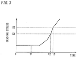
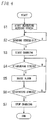
- the controller 1b After receiving the charging operation (after a time point t1 in FIG. 3 ), the controller 1b first starts a detection operation of bending stress through the stress detector 4 (S1), and then compares the bending stress exerted on the junction 5 with a threshold (a first threshold) K1 (S2). The controller 1b permits the power conversion circuit 1a to output charging power if the bending stress is below the threshold K1. The controller 1b also prohibits the power conversion circuit 1a from outputting the charging power if the bending stress is the threshold K1 or more.
- the controller 1b When permitting the output operation of the charging power, the controller 1b communicates with the electric vehicle 101 in accordance with a predetermined communication sequence and then controls the power conversion circuit 1a to allow the power conversion circuit 1a to output the charging power, thereby charging the storage battery 21 (S3).
- the controller 1b When prohibiting the output operation of the charging power, the controller 1b shows information about occurrence of a large bending stress through the display 1d formed of a liquid crystal display or the like, and makes an announcement of the occurrence of the large bending stress by voice through the sound output device 1e formed of speaker or the like. That is, the controller 1b prompts a user to change a tensile state of the electric cable 2 or a stopping place of the electric vehicle 101 to reduce the bending stress exerted on the junction 5, through the display 1d and the sound output device 1e. The user will reduce the bending stress exerted on the junction 5 and then perform the charging operation with the operation input device 1c again.
- the display 1d may be configured to perform the information-giving operation by any of message display by character representation, luminous display by lighting or blinking of a light source, or the like.
- the controller 1b monitors the bending stress exerted on the junction 5 based on the stress detection signal from the stress detector 4.
- the controller 1b compares the bending stress exerted on the junction 5 with the threshold K1 (S4). It is assumed that the bending stress exerted on the junction 5 becomes the threshold K1 or more as a result of a change in the tensile state of the electric cable 2 or movement of the electric vehicle 101. In this case, the controller 1b gives an alarm to the user through the display 1d and the sound output device 1e while continuing the output operation of the charging power through the power conversion circuit 1a (S5). That is, the display 1d shows information about occurrence of the large bending stress, and the sound output device 1e makes an announcement of the occurrence of the large bending stress by voice.
- the display 1d and the sound output device 1e can correspond to the notification portion of the present invention. Any one of the display 1d and the sound output device 1e may correspond to the notification portion of the present invention.
- the controller 1b compares the bending stress exerted on the junction 5 with a threshold (a second threshold) K2 (S6), where threshold K2 > threshold K1.
- a threshold a second threshold
- K2 threshold K1.
- the controller 1b stops output of the charging power from the power conversion circuit 1a (S7).
- the controller 1b Even if the bending stress exerted on the junction 5 becomes large as stated above, the controller 1b only gives an alarm to the user in a bending stress range of K1 to K2 in which there is no concern that any of the electric cable 2 and the connector 3 will be damaged (t2-t3 in FIG. 3 ). Thus, the user can recognize that the bending stress exerted on the junction 5 is large, without immediate release of the connector 3 from the inlet 22 like a conventional one.
- the user can therefore prevent damage to the electric cable 2 or the connector 3 by changing the tensile state of the electric cable 2 in a continuous state of charging to reduce bending stress exerted on the junction 5. That is, the vehicle power device 100 can prevent excessive stress from affecting the electric cable 2 and the connector 3, and provide users with the device having ease of use in comparison with the conventional one.
- the controller 1b stops the output of the charging power from the power conversion circuit 1a in a bending stress range of K2 or more in which there is a concern that any of the electric cable 2 and the connector 3 will be damaged (on or after the time point t3 in FIG. 3 ). During output of the charging power, it is therefore possible to prevent damage to the electric cable 2 or the connector 3 and to prevent the connector 3 from coming off the inlet 22.
- the controller 1b may further perform a control operation shown in FIGS. 5 and 6 based on a stress detection signal from the stress detector 4.
- the controller 1b changes the lock 3b from a locked state to an unlocked state (S9) (on or after a time point t4 in FIG. 5 ).
- the connector 3 is therefore released from the inlet 22 because the latch 3a is disabled by tensile strength of the electric cable 2 when the bending stress exerted on the junction 5 further increases.
- the vehicle power device 100 can prevent damage to the electric cable 2 or the connector 3, and collapse of the power converter 1.
- the embodiment can include following modified examples.
- a power converter 1A may be provided with a discharge circuit 11 as shown in FIG. 7 .
- the connection pins of the connector 3 released from an inlet 22 may be hidden so as to prohibit a user from directly touching the connection pins.
- a vehicle power device 100 can accordingly prevent a user from receiving electric shock by touching the connection pins of the connector 3 by accident.
- a switch 3c may be provided in a connector 3B, and configured to shut off charging power if a lock 3b is disabled.
- a controller 1b may be configured to control ON and OFF of the switch 3c, or configured to control ON and OFF of the switch 3c according to an operation of the lock 3b.
- a vehicle power device 100 can accordingly prevent a user from receiving electric shock by touching connection pins of the connector 3 by accident after the lock 3b is disabled. It is also possible to prevent a spark from occurring when the connector 3 is released.
- a vehicle power device 100C may be provided with an energizing member 31 configured to exert force on a connector 3 so that the connector 3 is automatically released from an inlet 22 when a lock 3b is disabled.
- the energizing member 31 may exert the force in a direction to release the connector 3 from the inlet 22 by spring force, electromagnetic repulsion force, air pressure, thermal expansion force or the like.
- the vehicle power device 100C can release the connector 3 from the inlet 22 through the energizing member 31. It is therefore possible to further prevent damage to an electric cable 2 or the connector 3, and collapse of a power converter 1.
- a vehicle power device 100 includes a power converter 1, an electric cable 2, a connector 3, a detector (a stress detector 4), and a notification portion (a display 1d and a sound output device 1e).
- the power converter 1 is configured to output charging power for charging a storage battery with which an electric vehicle is equipped.
- a first end of the electric cable 2 is connected to an output terminal of the power converter 1.
- the connector 3 is provided at a second end of the electric cable 2 and configured to be detachably attached to an inlet of the electric vehicle.
- the stress detector 4 is provided at a junction 5 where the electric cable 2 and the connector 3 are joined together, and configured to detect force exerted on the junction 5 by tensile strength of the electric cable 3.
- the display 1d and the sound output device 1e are configured to give an alarm to a user.
- the power converter 1 includes a power conversion circuit 1a configured to generate and output the charging power, and a controller 1b configured to control an operation of the power conversion circuit 1a.
- the controller 1b is configured to start an output operation of the charging power through the power conversion circuit 1a if the force detected with the stress detector 4 is below a first threshold.
- the controller 1b is configured to raise the alarm through the display 1d and the sound output device 1e if the force detected with the stress detector 4 is the first threshold or more when the power conversion circuit 1a outputs the charging power.
- the controller is also configured to stop the power conversion circuit 1a outputting the charging power if the force detected with the stress detector 4 is a second threshold or more when the power conversion circuit 1a outputs the charging power.
- the second threshold has a value larger than the first threshold.
- the vehicle power device 100 may include a lock 3b for preventing the connector 3 from being released from the inlet.
- the controller 1b is configured: to keep enabling the lock 3b if the force detected with the stress detector 4 is below a third threshold; and to disable the lock 3b if the force detected with the stress detector 4 is the third threshold or more.
- the third threshold is a value larger than the second threshold.
- the vehicle power device 100 may include a discharge circuit 11 configured to discharge a voltage across pins of the connector 3 before the lock 3b is disabled if the force detected with the stress detector 4 is the third threshold or more.
- the vehicle power device 100 may include a switch 3c configured to shut off the charging power if the lock 3b is disabled.
- the vehicle power device 100 may include an energizing member 31 configured to exert force on the connector in a direction to release the connector from the inlet if the lock 3b is disabled.
- the vehicle power device 100 equipped with the energizing member 31 corresponds to the vehicle power device 100C described in Modified Example 3.
- the stress detector 4 may be configured to detect a bending stress exerted on the junction 5.
- FIG. 10 shows a configuration of a vehicle power device (a battery charger and discharger) 100D according to the present embodiment.
- a vehicle power device a battery charger and discharger
- Like kind elements are assigned the same reference numerals as depicted in Embodiment 1 and Modified Examples 1 to 3, and explanation thereof is omitted.
- a power converter 1D includes a bidirectional power conversion circuit 1f in place of the power conversion circuit 1a.
- the bidirectional power conversion circuit 1f has a function configured to output charging power via an electric cable 2 and a connector 3 to charge a storage battery 21 like the power conversion circuit 1a.
- the bidirectional power conversion circuit 1f further has a function configured: to receive DC power (discharging power) supplied from the storage battery 21 of an electric vehicle 101 via the electric cable 2 and the connector 3; to convert the discharging power into a prescribed voltage (an AC voltage or a DC voltage); and to supply the converted voltage to a load(s) (not shown).
- the bidirectional power conversion circuit 1f is configured to perform bidirectional power conversion (charge and discharge of the storage battery 21) for allowing the storage battery 21 to charge and discharge via the electric cable 2 and the connector 3.
- An operation of the bidirectional power conversion circuit 1f is controlled by a controller 1b.
- a charging operation of the storage battery 21 is performed like Embodiment 1, and explanation thereof is accordingly omitted.
- a discharging operation of the storage battery 21 will be hereinafter explained.
- a user first attaches the connector 3 to an inlet 22 of the electric vehicle 101 to enable a latch 3a and then performs a charging operation with an operation input device 1c.
- the controller 1b when receiving the charging operation, the controller 1b enables the lock 3b to perform a process shown in FIG. 11 .
- the controller 1b After receiving the charging operation, the controller 1b first starts detecting bending stress with a stress detector 4 (S11), and then compares the bending stress exerted on a junction 5 with a threshold K1 (S12). The controller 1b permits the bidirectional power conversion circuit 1f to perform an operation for power conversion of the discharging power if the bending stress is below the threshold K1. The controller 1b prohibits the bidirectional power conversion circuit 1f from performing the operation for power conversion of the discharging power if the bending stress is the threshold K1 or more.
- the controller 1b When permitting the operation for power conversion of the discharging power, the controller 1b communicates with the electric vehicle 101 in accordance with a predetermined communication sequence and then controls the bidirectional power conversion circuit 1f to perform power conversion of the discharging power (S13).
- the controller 1b When prohibiting the operation for power conversion of the discharging power, the controller 1b shows information about occurrence of a large bending stress through a display 1d, and makes an announcement of the occurrence of the large bending stress by voice through a sound output device 1e. That is, the controller 1b prompts a user to change a tensile state of the electric cable 2 or a stopping place of the electric vehicle 101 to reduce the bending stress exerted on the junction 5, through the display 1d and the sound output device 1e. The user will reduce the bending stress exerted on the junction 5 and then perform the charging operation with the operation input device 1c again.
- the display 1d may be configured to perform the information-giving operation by any of message display by character representation, luminous display by lighting or blinking of a light source, or the like.
- the controller 1b monitors the bending stress exerted on the junction 5 based on a stress detection signal from the stress detector 4.
- the controller 1b compares the bending stress exerted on the junction 5 with the threshold K1 (S14). It is assumed that the bending stress exerted on the junction 5 becomes the threshold K1 or more as a result of a change in the tensile state of the electric cable 2 or movement of the electric vehicle 101. In this case, the controller 1b gives an alarm to the user through the display 1d and the sound output device 1e while continuing the operation for power conversion through the bidirectional power conversion circuit 1f (S15). That is, the display 1d shows information about occurrence of the large bending stress, and the sound output device 1e makes an announcement of the occurrence of the large bending stress by voice.
- the controller 1b compares the bending stress exerted on the junction 5 with a threshold K2 (S16). When the bending stress becomes the threshold K2 or more as a result of a further increase in the bending stress, the controller 1b stops the bidirectional power conversion circuit 1f performing the operation for power conversion of the discharging power (S17).
- the controller 1b Even if the bending stress exerted on the junction 5 becomes large as stated above, the controller 1b only gives an alarm to the user in a bending stress range of K1 to K2 in which there is no concern that any of the electric cable 2 and the connector 3 will be damaged. Thus, the user can recognize that the bending stress exerted on the junction 5 is large, without immediate release of the connector 3 from the inlet 22 like the conventional one.
- the user can therefore prevent damage to the electric cable 2 or the connector 3 by changing the tensile state of the electric cable 2 in a continuous state of discharging to reduce bending stress exerted on the junction 5. That is, the vehicle power device 100D can prevent excessive stress from affecting the electric cable 2 and the connector 3, and provide users with the device having ease of use in comparison with the conventional one.
- the controller 1b stops the bidirectional power conversion circuit 1f performing the operation for power conversion of the discharging power in a bending stress range of K2 or more in which there is a concern that any of the electric cable 2 and the connector 3 will be damaged. During the power conversion of the discharging power, it is therefore possible to prevent damage to the electric cable 2 or the connector 3 and to prevent the connector 3 from coming off the inlet 22.
- the controller 1b stops the bidirectional power conversion circuit 1f performing the operation for power conversion of the discharging power at step S17, the bending stress exerted on the junction 5 further increases and is a threshold K3 or more (S18).
- the controller 1b changes the lock 3b from a locked state to an unlocked state (S19).
- the connector 3 is therefore released from the inlet 22 because the latch 3a is disabled by tensile strength of the electric cable 2 when the bending stress exerted on the junction 5 further increases.
- the vehicle power device 100D can prevent damage to the electric cable 2 or the connector 3, and collapse of the power converter 1D.
- Each of the embodiments detects bending stress exerted on the junction 5 by tensile strength of the electric cable 2, but may detect another parameter such as pressure exerted on the junction or distortion thereof.
- a bidirectional power conversion circuit 1f (a power converter) may be configured to receive discharging power of a storage battery via a connector 3 and an electric cable 2 to perform power conversion of the discharging power to output the converted power.
- a controller 1b is configured to start the power conversion of the discharging power through the bidirectional power conversion circuit 1f if force detected with a stress detector 4 (the detector) is below a first threshold.
- the controller 1b is configured to raise an alarm through a notification portion if the force detected with a stress detector 4 is the first threshold or more when the bidirectional power conversion circuit 1f performs the power conversion of the discharging power.
- the controller 1b is configured to stop the bidirectional power conversion circuit 1f performing the power conversion of the discharging power if the force detected with a stress detector 4 is a second threshold or more when the bidirectional power conversion circuit 1f performs the power conversion of the discharging power.
Landscapes
- Engineering & Computer Science (AREA)
- Power Engineering (AREA)
- Transportation (AREA)
- Mechanical Engineering (AREA)
- Sustainable Energy (AREA)
- Sustainable Development (AREA)
- Life Sciences & Earth Sciences (AREA)
- General Chemical & Material Sciences (AREA)
- Electrochemistry (AREA)
- Chemical Kinetics & Catalysis (AREA)
- Chemical & Material Sciences (AREA)
- Manufacturing & Machinery (AREA)
- Electric Propulsion And Braking For Vehicles (AREA)
- Details Of Connecting Devices For Male And Female Coupling (AREA)
- Charge And Discharge Circuits For Batteries Or The Like (AREA)
- Secondary Cells (AREA)
Abstract
Description
- The invention relates generally to vehicle power devices and, more particularly, to a vehicle power device configured to control charging of a storage battery of an electric vehicle.
- Environmentally friendly electric vehicles with less toxic exhaust have been recently introduced in markets, thereby diffusing vehicle power devices that allow a storage battery of an electric vehicle to charge and discharge. Examples of an electric vehicle include an Electric Vehicle (EV), a Plug-in Hybrid Electric Vehicle (PHEV) and the like.
- A vehicle power device configured to charge an electric vehicle has a power converter configured to output charging power for charging a storage battery thereof. An output of the power converter is connected with a first end of a charging cable. A second end of the charging cable is connected with a connector that is detachably attached to an inlet with which an electric vehicle is equipped. The power converter is to supply the charging power to the storage battery of the electric vehicle via the charging cable and the connector.
- There is however a concern about damage to the charging cable or the connector caused by excessive stress exerted on the charging cable or the connector when the charging cable is pulled with the connector attached to the inlet.
- There has been therefore proposed a configuration in which a strain gauge or a pressure sensor is installed in the connector or the charging cable and configured to detect excessive force exerted in a direction such that the connector is detached from the inlet. When detecting the excessive force in the direction such that the connector is detached from the inlet, the conventional configuration releases a latch between the connector and the inlet to allow the connector to release from the inlet (e.g., PTL 1).
- PTL 1:
JP Pub. No. 2011-187175 - In
PTL 1, when a stress is exerted on the charging cable and the connector, a connection between the connector and the inlet is immediately released. In this case, a user needs to attach the connector to the inlet again. Thus, the user needs to attach the connector, which was attached to the inlet, thereto again, and it is accordingly inconvenient for the user to handle it. - The present invention has been achieved in view of the above circumstances, and an object thereof is to provide a vehicle power device that is easy to handle and prevents excessive stress from being exerted on an electric cable and a connector.
- A vehicle power device of the invention includes a power converter, an electric cable, a connector, a detector and a notification portion. The power converter is configured to output charging power for charging a storage battery with which an electric vehicle is equipped. A first end of the electric cable is connected to an output of the power converter. The connector is provided at a second end of the electric cable and configured to be detachably attached to an inlet of the electric vehicle. The detector is provided at a junction where the electric cable and the connector are joined together, and configured to detect force exerted on the junction by tensile strength of the electric cable. The notification portion is configured to give an alarm to a user. The power converter includes a power conversion circuit configured to generate and output the charging power, and a controller configured to control an operation of the power conversion circuit. The controller is configured: to start an output operation of the charging power through the power conversion circuit if the detected force is below a first threshold; to raise the alarm through the notification portion if the detected force is the first threshold or more when the power conversion circuit outputs the charging power; and to stop the power conversion circuit outputting the charging power if the detected force is a second threshold or more when the power conversion circuit outputs the charging power. The second threshold is above the first threshold.
- According to an aspect of the invention, the vehicle power device includes a lock for preventing the connector from being released from the inlet. The controller is configured: to keep enabling the lock if the detected force is below a third threshold; and to disable the lock if the detected force is the third threshold or more. The third threshold is above the second threshold.
- According to an aspect of the invention, the vehicle power device preferably includes a discharge circuit configured to discharge a voltage across pins of the connector before the lock is disabled if the detected force is the third threshold or more.
- According to an aspect of the invention, the vehicle power device preferably includes a switch configured to shut off the charging power if the lock is disabled.
- According to an aspect of the invention, the vehicle power device preferably includes an energizing member configured to exert force on the connector in a direction to release the connector from the inlet if the lock is disabled.
- In the invention, preferably the detector is configured to detect bending stress exerted on the junction.
- In the invention, preferably the power conversion circuit is configured to receive discharging power of the storage battery via the connector and the electric cable to perform power conversion of the discharging power to output the converted power. Preferably, the controller is configured: to start the power conversion of the discharging power through the power conversion circuit if the detected force is below the first threshold; to raise the alarm through the notification portion if the detected force is the first threshold or more when the power conversion circuit performs the power conversion of the discharging power; and to stop the power conversion circuit performing the power conversion of the discharging power if the detected force is a second threshold or more when the power conversion circuit performs the power conversion of the discharging power.
- As stated above, in the invention, a user can prevent damage to the electric cable or the connector by changing tensile state of the electric cable in a continuous state of charging to reduce bending stress exerted on the junction. That is, it is possible to prevent excessive stress from affecting the electric cable and the connector, and provide users with the vehicle power device having ease of use in comparison with the conventional one.
-
-
FIG. 1 is a block diagram showing a configuration of a vehicle power device in accordance withEmbodiment 1; -
FIG. 2 is a schematic diagram showing a configuration around a junction between an electric cable and a connector inEmbodiment 1; -
FIG. 3 is a view illustrating an operation of a system inEmbodiment 1; -
FIG. 4 is a flow chart depicting the operation of the system inEmbodiment 1; -
FIG. 5 is a view illustrating another operation of the system inEmbodiment 1; -
FIG. 6 is a flow chart depicting the operation of the system inEmbodiment 1; -
FIG. 7 is a block diagram showing a configuration of a vehicle power device in Modified Example 1; -
FIG. 8 is a schematic diagram showing a configuration around a junction between an electric cable and a connector in Modified Example 2; -
FIG. 9 is a block diagram showing a configuration of a vehicle power device in Modified Example 3; -
FIG. 10 is a block diagram showing a configuration of a vehicle power device inEmbodiment 2; and -
FIG. 11 is a flow chart depicting an operation of a system inEmbodiment 2. - Embodiments of the present invention will be hereinafter explained with reference to drawings.
-
FIG. 1 shows a configuration of a vehicle power device (a battery charger) 100 according to the embodiment. Thevehicle power device 100 is configured to supply charging power to astorage battery 21 with which anelectric vehicle 101 such as an electric vehicle (EV) or a plug-in hybrid electric vehicle (PHEV) is equipped, thereby charging thestorage battery 21. - The
vehicle power device 100 includes apower converter 1, anelectric cable 2 and aconnector 3. - The
power converter 1 is formed of a power conversion circuit 1a, acontroller 1b, anoperation input device 1c, adisplay 1d and asound output device 1e. The power conversion circuit 1a is configured, in accordance with operation control of thecontroller 1b, to convert commercial power as a power supply to DC power to output the DC power as charging power. An output (terminal) of the power conversion circuit 1a is connected with a first end of theelectric cable 2, and a side of a second end of theelectric cable 2 is lead out of thepower converter 1. The second end of theelectric cable 2 is provided with theconnector 3. Theconnector 3 is configured to be detachably attached to aninlet 22 provided in an exterior surface of a body of theelectric vehicle 101. Theinlet 22 is electrically connected to charging lines (not shown) provided in theelectric vehicle 101 in order to charge thestorage battery 21. That is, thepower converter 1 can charge thestorage battery 21 of theelectric vehicle 101 by supplying the charging power produced by the power conversion circuit 1a thereto via theelectric cable 2 and theconnector 3. Theelectric cable 2 has a power supply line for supplying the charging power from the power conversion circuit 1a to thestorage battery 21, and a signal line through which thecontroller 1b is configured to transmit a control signal for enabling and disabling alock 3b to be described below. -
FIG. 2 shows a schematic diagram around ajunction 5 where theelectric cable 2 and theconnector 3 are joined together. InFIG. 2 , thejunction 5 is formed of a bushing. - The
connector 3 includes alatch 3a that is formed of an engaging claw or the like configured to be mechanically fixed to theinlet 22. Theconnector 3 includes thelock 3b. Thelock 3b is configured, during charging, to electrically lock thelatch 3a so that theconnector 3 is prevented from being released from theinlet 22 as a result of thelatch 3a being disabled by tensile strength of theelectric cable 2 or a human operation with respect to thelatch 3a. Thelock 3b includes a solenoid valve, and is configured to enable the lock and also to disable the lock (to release the lock) by driving the solenoid valve. Thecontroller 1b is configured to control enabling and disabling of thelock 3b by driving the solenoid valve though the signal line in theelectric cable 2. - A
stress detector 4 is provided between theelectric cable 2 and theconnector 3 along with thejunction 5, and configured to detect bending stress exerted on thejunction 5 by tensile strength of theelectric cable 2. Thestress detector 4 is formed of piezoelectric devices provided in or around thejunction 5. Each of the piezoelectric devices is configured to generate a voltage according to the bending stress exerted on thejunction 5. Thestress detector 4 is also configured to supply a signal (a stress detection signal) according to the bending stress to thecontroller 1b via the signal line in theelectric cable 2. Thecontroller 1b is configured to control the power conversion circuit 1a based on the stress detection signal from thestress detector 4. - A user is to first perform a charging operation through the
operation input device 1c after attaching theconnector 3 to theinlet 22 of theelectric vehicle 101 to enable thelatch 3a. When receiving the charging operation, thecontroller 1b enables thelock 3b to perform a process shown inFIGS. 3 and4 . - After receiving the charging operation (after a time point t1 in
FIG. 3 ), thecontroller 1b first starts a detection operation of bending stress through the stress detector 4 (S1), and then compares the bending stress exerted on thejunction 5 with a threshold (a first threshold) K1 (S2). Thecontroller 1b permits the power conversion circuit 1a to output charging power if the bending stress is below the threshold K1. Thecontroller 1b also prohibits the power conversion circuit 1a from outputting the charging power if the bending stress is the threshold K1 or more. - When permitting the output operation of the charging power, the
controller 1b communicates with theelectric vehicle 101 in accordance with a predetermined communication sequence and then controls the power conversion circuit 1a to allow the power conversion circuit 1a to output the charging power, thereby charging the storage battery 21 (S3). - When prohibiting the output operation of the charging power, the
controller 1b shows information about occurrence of a large bending stress through thedisplay 1d formed of a liquid crystal display or the like, and makes an announcement of the occurrence of the large bending stress by voice through thesound output device 1e formed of speaker or the like. That is, thecontroller 1b prompts a user to change a tensile state of theelectric cable 2 or a stopping place of theelectric vehicle 101 to reduce the bending stress exerted on thejunction 5, through thedisplay 1d and thesound output device 1e. The user will reduce the bending stress exerted on thejunction 5 and then perform the charging operation with theoperation input device 1c again. Thedisplay 1d may be configured to perform the information-giving operation by any of message display by character representation, luminous display by lighting or blinking of a light source, or the like. - Even while the power conversion circuit 1a is outputting the charging power after starting the output operation of the charging power, the
controller 1b monitors the bending stress exerted on thejunction 5 based on the stress detection signal from thestress detector 4. - The
controller 1b compares the bending stress exerted on thejunction 5 with the threshold K1 (S4). It is assumed that the bending stress exerted on thejunction 5 becomes the threshold K1 or more as a result of a change in the tensile state of theelectric cable 2 or movement of theelectric vehicle 101. In this case, thecontroller 1b gives an alarm to the user through thedisplay 1d and thesound output device 1e while continuing the output operation of the charging power through the power conversion circuit 1a (S5). That is, thedisplay 1d shows information about occurrence of the large bending stress, and thesound output device 1e makes an announcement of the occurrence of the large bending stress by voice. Thedisplay 1d and thesound output device 1e can correspond to the notification portion of the present invention. Any one of thedisplay 1d and thesound output device 1e may correspond to the notification portion of the present invention. - The
controller 1b then compares the bending stress exerted on thejunction 5 with a threshold (a second threshold) K2 (S6), where threshold K2 > threshold K1. When the bending stress becomes the threshold K2 or more as a result of a further increase in the bending stress, thecontroller 1b stops output of the charging power from the power conversion circuit 1a (S7). - Even if the bending stress exerted on the
junction 5 becomes large as stated above, thecontroller 1b only gives an alarm to the user in a bending stress range of K1 to K2 in which there is no concern that any of theelectric cable 2 and theconnector 3 will be damaged (t2-t3 inFIG. 3 ). Thus, the user can recognize that the bending stress exerted on thejunction 5 is large, without immediate release of theconnector 3 from theinlet 22 like a conventional one. - The user can therefore prevent damage to the
electric cable 2 or theconnector 3 by changing the tensile state of theelectric cable 2 in a continuous state of charging to reduce bending stress exerted on thejunction 5. That is, thevehicle power device 100 can prevent excessive stress from affecting theelectric cable 2 and theconnector 3, and provide users with the device having ease of use in comparison with the conventional one. - When the bending stress exerted on the
junction 5 further increases, thecontroller 1b stops the output of the charging power from the power conversion circuit 1a in a bending stress range of K2 or more in which there is a concern that any of theelectric cable 2 and theconnector 3 will be damaged (on or after the time point t3 inFIG. 3 ). During output of the charging power, it is therefore possible to prevent damage to theelectric cable 2 or theconnector 3 and to prevent theconnector 3 from coming off theinlet 22. - In addition, when receiving the charging operation, the
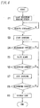
controller 1b may further perform a control operation shown inFIGS. 5 and6 based on a stress detection signal from thestress detector 4. - Specifically, it is assumed that after the power conversion circuit 1a stops outputting charging power at step S7, the bending stress exerted on the
junction 5 further increases and is a threshold K3 or more (S8). In this case, thecontroller 1b changes thelock 3b from a locked state to an unlocked state (S9) (on or after a time point t4 inFIG. 5 ). Theconnector 3 is therefore released from theinlet 22 because thelatch 3a is disabled by tensile strength of theelectric cable 2 when the bending stress exerted on thejunction 5 further increases. Thus, thevehicle power device 100 can prevent damage to theelectric cable 2 or theconnector 3, and collapse of thepower converter 1. - The embodiment can include following modified examples.
- In order to allow a voltage across connection pins of a
connector 3 to discharge before thelock 3b is disabled, apower converter 1A may be provided with adischarge circuit 11 as shown inFIG. 7 . Alternatively, the connection pins of theconnector 3 released from aninlet 22 may be hidden so as to prohibit a user from directly touching the connection pins. Avehicle power device 100 can accordingly prevent a user from receiving electric shock by touching the connection pins of theconnector 3 by accident. - As shown in
FIG. 8 , aswitch 3c may be provided in aconnector 3B, and configured to shut off charging power if alock 3b is disabled. Acontroller 1b may be configured to control ON and OFF of theswitch 3c, or configured to control ON and OFF of theswitch 3c according to an operation of thelock 3b. Avehicle power device 100 can accordingly prevent a user from receiving electric shock by touching connection pins of theconnector 3 by accident after thelock 3b is disabled. It is also possible to prevent a spark from occurring when theconnector 3 is released. - As shown in
FIG. 9 , avehicle power device 100C may be provided with an energizingmember 31 configured to exert force on aconnector 3 so that theconnector 3 is automatically released from aninlet 22 when alock 3b is disabled. For example, the energizingmember 31 may exert the force in a direction to release theconnector 3 from theinlet 22 by spring force, electromagnetic repulsion force, air pressure, thermal expansion force or the like. In this case, thevehicle power device 100C can release theconnector 3 from theinlet 22 through the energizingmember 31. It is therefore possible to further prevent damage to anelectric cable 2 or theconnector 3, and collapse of apower converter 1. - As stated above, a
vehicle power device 100 according toEmbodiment 1 includes apower converter 1, anelectric cable 2, aconnector 3, a detector (a stress detector 4), and a notification portion (adisplay 1d and asound output device 1e). Thepower converter 1 is configured to output charging power for charging a storage battery with which an electric vehicle is equipped. A first end of theelectric cable 2 is connected to an output terminal of thepower converter 1. Theconnector 3 is provided at a second end of theelectric cable 2 and configured to be detachably attached to an inlet of the electric vehicle. Thestress detector 4 is provided at ajunction 5 where theelectric cable 2 and theconnector 3 are joined together, and configured to detect force exerted on thejunction 5 by tensile strength of theelectric cable 3. Thedisplay 1d and thesound output device 1e are configured to give an alarm to a user. Thepower converter 1 includes a power conversion circuit 1a configured to generate and output the charging power, and acontroller 1b configured to control an operation of the power conversion circuit 1a. Thecontroller 1b is configured to start an output operation of the charging power through the power conversion circuit 1a if the force detected with thestress detector 4 is below a first threshold. Thecontroller 1b is configured to raise the alarm through thedisplay 1d and thesound output device 1e if the force detected with thestress detector 4 is the first threshold or more when the power conversion circuit 1a outputs the charging power. The controller is also configured to stop the power conversion circuit 1a outputting the charging power if the force detected with thestress detector 4 is a second threshold or more when the power conversion circuit 1a outputs the charging power. The second threshold has a value larger than the first threshold. - In the embodiment, the
vehicle power device 100 may include alock 3b for preventing theconnector 3 from being released from the inlet. Thecontroller 1b is configured: to keep enabling thelock 3b if the force detected with thestress detector 4 is below a third threshold; and to disable thelock 3b if the force detected with thestress detector 4 is the third threshold or more. The third threshold is a value larger than the second threshold. - In the embodiment, the
vehicle power device 100 may include adischarge circuit 11 configured to discharge a voltage across pins of theconnector 3 before thelock 3b is disabled if the force detected with thestress detector 4 is the third threshold or more. - In the embodiment, the
vehicle power device 100 may include aswitch 3c configured to shut off the charging power if thelock 3b is disabled. - In the embodiment, the
vehicle power device 100 may include an energizingmember 31 configured to exert force on the connector in a direction to release the connector from the inlet if thelock 3b is disabled. Thevehicle power device 100 equipped with the energizingmember 31 corresponds to thevehicle power device 100C described in Modified Example 3. - In the embodiment, the
stress detector 4 may be configured to detect a bending stress exerted on thejunction 5. -
FIG. 10 shows a configuration of a vehicle power device (a battery charger and discharger) 100D according to the present embodiment. Like kind elements are assigned the same reference numerals as depicted inEmbodiment 1 and Modified Examples 1 to 3, and explanation thereof is omitted. - A
power converter 1D includes a bidirectional power conversion circuit 1f in place of the power conversion circuit 1a. The bidirectional power conversion circuit 1f has a function configured to output charging power via anelectric cable 2 and aconnector 3 to charge astorage battery 21 like the power conversion circuit 1a. The bidirectional power conversion circuit 1f further has a function configured: to receive DC power (discharging power) supplied from thestorage battery 21 of anelectric vehicle 101 via theelectric cable 2 and theconnector 3; to convert the discharging power into a prescribed voltage (an AC voltage or a DC voltage); and to supply the converted voltage to a load(s) (not shown). That is, the bidirectional power conversion circuit 1f is configured to perform bidirectional power conversion (charge and discharge of the storage battery 21) for allowing thestorage battery 21 to charge and discharge via theelectric cable 2 and theconnector 3. An operation of the bidirectional power conversion circuit 1f is controlled by acontroller 1b. - A charging operation of the
storage battery 21 is performed likeEmbodiment 1, and explanation thereof is accordingly omitted. A discharging operation of thestorage battery 21 will be hereinafter explained. - It is assumed that a user first attaches the
connector 3 to aninlet 22 of theelectric vehicle 101 to enable alatch 3a and then performs a charging operation with anoperation input device 1c. In this case, when receiving the charging operation, thecontroller 1b enables thelock 3b to perform a process shown inFIG. 11 . - After receiving the charging operation, the
controller 1b first starts detecting bending stress with a stress detector 4 (S11), and then compares the bending stress exerted on ajunction 5 with a threshold K1 (S12). Thecontroller 1b permits the bidirectional power conversion circuit 1f to perform an operation for power conversion of the discharging power if the bending stress is below the threshold K1. Thecontroller 1b prohibits the bidirectional power conversion circuit 1f from performing the operation for power conversion of the discharging power if the bending stress is the threshold K1 or more. - When permitting the operation for power conversion of the discharging power, the
controller 1b communicates with theelectric vehicle 101 in accordance with a predetermined communication sequence and then controls the bidirectional power conversion circuit 1f to perform power conversion of the discharging power (S13). - When prohibiting the operation for power conversion of the discharging power, the
controller 1b shows information about occurrence of a large bending stress through adisplay 1d, and makes an announcement of the occurrence of the large bending stress by voice through asound output device 1e. That is, thecontroller 1b prompts a user to change a tensile state of theelectric cable 2 or a stopping place of theelectric vehicle 101 to reduce the bending stress exerted on thejunction 5, through thedisplay 1d and thesound output device 1e. The user will reduce the bending stress exerted on thejunction 5 and then perform the charging operation with theoperation input device 1c again. Thedisplay 1d may be configured to perform the information-giving operation by any of message display by character representation, luminous display by lighting or blinking of a light source, or the like. - Even while the bidirectional power conversion circuit 1f is performing the power conversion of the discharging power after starting the operation for power conversion of the discharging power, the
controller 1b monitors the bending stress exerted on thejunction 5 based on a stress detection signal from thestress detector 4. - The
controller 1b compares the bending stress exerted on thejunction 5 with the threshold K1 (S14). It is assumed that the bending stress exerted on thejunction 5 becomes the threshold K1 or more as a result of a change in the tensile state of theelectric cable 2 or movement of theelectric vehicle 101. In this case, thecontroller 1b gives an alarm to the user through thedisplay 1d and thesound output device 1e while continuing the operation for power conversion through the bidirectional power conversion circuit 1f (S15). That is, thedisplay 1d shows information about occurrence of the large bending stress, and thesound output device 1e makes an announcement of the occurrence of the large bending stress by voice. - The
controller 1b then compares the bending stress exerted on thejunction 5 with a threshold K2 (S16). When the bending stress becomes the threshold K2 or more as a result of a further increase in the bending stress, thecontroller 1b stops the bidirectional power conversion circuit 1f performing the operation for power conversion of the discharging power (S17). - Even if the bending stress exerted on the
junction 5 becomes large as stated above, thecontroller 1b only gives an alarm to the user in a bending stress range of K1 to K2 in which there is no concern that any of theelectric cable 2 and theconnector 3 will be damaged. Thus, the user can recognize that the bending stress exerted on thejunction 5 is large, without immediate release of theconnector 3 from theinlet 22 like the conventional one. - The user can therefore prevent damage to the
electric cable 2 or theconnector 3 by changing the tensile state of theelectric cable 2 in a continuous state of discharging to reduce bending stress exerted on thejunction 5. That is, thevehicle power device 100D can prevent excessive stress from affecting theelectric cable 2 and theconnector 3, and provide users with the device having ease of use in comparison with the conventional one. - When the bending stress exerted on the
junction 5 further increases, thecontroller 1b stops the bidirectional power conversion circuit 1f performing the operation for power conversion of the discharging power in a bending stress range of K2 or more in which there is a concern that any of theelectric cable 2 and theconnector 3 will be damaged. During the power conversion of the discharging power, it is therefore possible to prevent damage to theelectric cable 2 or theconnector 3 and to prevent theconnector 3 from coming off theinlet 22. - It is assumed that after the
controller 1b stops the bidirectional power conversion circuit 1f performing the operation for power conversion of the discharging power at step S17, the bending stress exerted on thejunction 5 further increases and is a threshold K3 or more (S18). In this case, thecontroller 1b changes thelock 3b from a locked state to an unlocked state (S19). Theconnector 3 is therefore released from theinlet 22 because thelatch 3a is disabled by tensile strength of theelectric cable 2 when the bending stress exerted on thejunction 5 further increases. Thus, thevehicle power device 100D can prevent damage to theelectric cable 2 or theconnector 3, and collapse of thepower converter 1D. - Each of the embodiments detects bending stress exerted on the
junction 5 by tensile strength of theelectric cable 2, but may detect another parameter such as pressure exerted on the junction or distortion thereof. - As stated above, a bidirectional power conversion circuit 1f (a power converter) according to the embodiment may be configured to receive discharging power of a storage battery via a
connector 3 and anelectric cable 2 to perform power conversion of the discharging power to output the converted power. Acontroller 1b is configured to start the power conversion of the discharging power through the bidirectional power conversion circuit 1f if force detected with a stress detector 4 (the detector) is below a first threshold. Thecontroller 1b is configured to raise an alarm through a notification portion if the force detected with astress detector 4 is the first threshold or more when the bidirectional power conversion circuit 1f performs the power conversion of the discharging power. Thecontroller 1b is configured to stop the bidirectional power conversion circuit 1f performing the power conversion of the discharging power if the force detected with astress detector 4 is a second threshold or more when the bidirectional power conversion circuit 1f performs the power conversion of the discharging power.
Claims (7)
- A vehicle power device, comprising:a power converter configured to output charging power for charging a storage battery with which an electric vehicle is equipped;an electric cable, a first end of which is connected to an output of the power converter;a connector which is provided at a second end of the electric cable and configured to be detachably attached to an inlet of the electric vehicle;a detector which is provided at a junction where the electric cable and the connector are joined together, the detector being configured to detect force exerted on the junction by tensile strength of the electric cable; anda notification portion configured to give an alarm to a user, whereinthe power converter comprises a power conversion circuit configured to generate and output the charging power, and a controller configured to control an operation of the power conversion circuit, andthe controller is configured
to start an output operation of the charging power through the power conversion circuit if the detected force is below a first threshold,
to raise the alarm through the notification portion if the detected force is the first threshold or more when the power conversion circuit outputs the charging power, and
to stop the power conversion circuit outputting the charging power if the detected force is a second threshold or more when the power conversion circuit outputs the charging power, the second threshold being above the first threshold. - The vehicle power device of claim 1, comprising a lock for preventing the connector from being released from the inlet, wherein
the controller is configured
to keep enabling the lock if the detected force is below a third threshold that is above the second threshold, and
to disable the lock if the detected force is the third threshold or more. - The vehicle power device of claim 2, comprising a discharge circuit configured to discharge a voltage across pins of the connector before the lock is disabled if the detected force is the third threshold or more.
- The vehicle power device of claim 2, comprising a switch configured to shut off the charging power if the lock is disabled.
- The vehicle power device of claim 2, comprising an energizing member configured to exert force on the connector in a direction to release the connector from the inlet if the lock is disabled.
- The vehicle power device of any one of claims 1 to 5, wherein the detector is configured to detect bending stress exerted on the junction.
- The vehicle power device of any one of claims 1 to 6, wherein
the power conversion circuit is configured to receive discharging power of the storage battery via the connector and the electric cable to perform power conversion of the discharging power to output the converted power, and
the controller is configured
to start the power conversion of the discharging power through the power conversion circuit if the detected force is below the first threshold,
to raise the alarm through the notification portion if the detected force is the first threshold or more when the power conversion circuit performs the power conversion of the discharging power, and
to stop the power conversion circuit performing the power conversion of the discharging power if the detected force is a second threshold or more when the power conversion circuit performs the power conversion of the discharging power.
Applications Claiming Priority (2)
| Application Number | Priority Date | Filing Date | Title |
|---|---|---|---|
| JP2013067100A JP2014193039A (en) | 2013-03-27 | 2013-03-27 | Vehicle power equipment |
| PCT/JP2014/001454 WO2014156030A1 (en) | 2013-03-27 | 2014-03-14 | Vehicle power unit |
Publications (2)
| Publication Number | Publication Date |
|---|---|
| EP2980955A1 true EP2980955A1 (en) | 2016-02-03 |
| EP2980955A4 EP2980955A4 (en) | 2016-05-25 |
Family
ID=51623050
Family Applications (1)
| Application Number | Title | Priority Date | Filing Date |
|---|---|---|---|
| EP14774000.5A Withdrawn EP2980955A4 (en) | 2013-03-27 | 2014-03-14 | VEHICLE POWER SUPPLY UNIT |
Country Status (5)
| Country | Link |
|---|---|
| US (1) | US20160059718A1 (en) |
| EP (1) | EP2980955A4 (en) |
| JP (1) | JP2014193039A (en) |
| CN (1) | CN105075057A (en) |
| WO (1) | WO2014156030A1 (en) |
Cited By (3)
| Publication number | Priority date | Publication date | Assignee | Title |
|---|---|---|---|---|
| DE102016225143B4 (en) * | 2016-12-15 | 2020-03-12 | Audi Ag | Motor vehicle and charging device with this motor vehicle |
| WO2021144099A1 (en) * | 2020-01-17 | 2021-07-22 | Phoenix Contact E-Mobility Gmbh | Plug connector part with a sensor device |
| DE102022121846A1 (en) | 2022-08-30 | 2024-02-29 | Dr. Ing. H.C. F. Porsche Aktiengesellschaft | Charging device for charging a traction battery of an electric vehicle |
Families Citing this family (15)
| Publication number | Priority date | Publication date | Assignee | Title |
|---|---|---|---|---|
| JP6142894B2 (en) * | 2015-04-10 | 2017-06-07 | トヨタ自動車株式会社 | Vehicle power supply |
| KR101736998B1 (en) * | 2016-02-01 | 2017-05-17 | 현대자동차주식회사 | Electric vehicle charging connector anti-theft method and apparatus |
| JP2020060417A (en) * | 2018-10-09 | 2020-04-16 | ファナック株式会社 | Anomaly detection device and anomaly detection system |
| CN109250589A (en) * | 2018-10-30 | 2019-01-22 | 安徽华星智能停车设备有限公司 | Three-dimensional parking device electric car charge cable draw off gear |
| JP7299128B2 (en) * | 2019-10-08 | 2023-06-27 | 株式会社東光高岳 | Power supply connector extension device |
| WO2021254635A1 (en) * | 2020-06-19 | 2021-12-23 | Vestel Elektronik Sanayi Ve Ticaret A.S. | Electronic device for determining the environmental risk of a charging cable and a charging cable |
| CN112319259B (en) * | 2020-11-13 | 2022-07-29 | 东风汽车股份有限公司 | Control system and control method for alternating-current charging electronic lock of electric automobile |
| EP4105625A1 (en) * | 2021-06-18 | 2022-12-21 | Volvo Car Corporation | A cable system for cable condition monitoring |
| DE102022201133A1 (en) | 2022-02-03 | 2023-08-03 | Volkswagen Aktiengesellschaft | Method and device for securing a charging process, in particular for a battery-powered vehicle |
| IT202200023391A1 (en) * | 2022-11-14 | 2024-05-14 | Matteo OVI | CHARGING SYSTEM FOR ELECTRIC OR SIMILAR VEHICLES |
| US20240239216A1 (en) * | 2023-01-13 | 2024-07-18 | Ford Global Technologies, Llc | Vehicle charger control system and method |
| CN116118539B (en) * | 2023-04-18 | 2023-09-12 | 深圳聚优精密工业有限公司 | Plug energy storage connection structure |
| DE102023119355A1 (en) * | 2023-07-21 | 2025-01-23 | Bayerische Motoren Werke Aktiengesellschaft | Connection unit, vehicle with the connection unit and process |
| FR3160635A1 (en) * | 2024-03-26 | 2025-10-03 | Stellantis Auto Sas | METHOD FOR BLOCKING AN AUTOMATIC MANEUVER OF AN ELECTRIC OR HYBRID MOTOR VEHICLE |
| CN118683382B (en) * | 2024-06-12 | 2025-01-17 | 广州市海皇科技有限公司 | Ship and shore integrated management control system and method |
Family Cites Families (18)
| Publication number | Priority date | Publication date | Assignee | Title |
|---|---|---|---|---|
| JPS61147540U (en) * | 1985-03-04 | 1986-09-11 | ||
| JP3181969B2 (en) * | 1992-03-27 | 2001-07-03 | 日産自動車株式会社 | Charging device |
| US5344331A (en) * | 1993-01-15 | 1994-09-06 | Hubbell Incorporated | Electrical connector system, especially for electric vehicles |
| US5385480A (en) * | 1993-01-15 | 1995-01-31 | Hubell Incorporated | Electrical connector inlet assembly with break-away mechanism for electric vehicle |
| JPH06343204A (en) * | 1993-06-01 | 1994-12-13 | Nissan Motor Co Ltd | Electric vehicle charging device |
| US5786682A (en) * | 1996-08-07 | 1998-07-28 | Reltec Corporation | Battery charging circuit including a current limiter which compares a reference current to a charging current to ensure operation of a load |
| JP3248519B2 (en) * | 1999-05-25 | 2002-01-21 | 日本電気株式会社 | Submarine cable discharge circuit |
| JP2002195899A (en) * | 2000-12-27 | 2002-07-10 | Oki Electric Ind Co Ltd | Trouble preventing device |
| US7683570B2 (en) * | 2007-07-18 | 2010-03-23 | Tesla Motors, Inc. | Systems, methods, and apparatus for battery charging |
| JP5243971B2 (en) * | 2009-01-05 | 2013-07-24 | 株式会社アルファ | Cable wiring structure |
| CN101953015A (en) * | 2009-01-07 | 2011-01-19 | 松下电器产业株式会社 | Battery charging method and battery charging system |
| JP2010226840A (en) * | 2009-03-23 | 2010-10-07 | Toyota Motor Corp | Vehicle and charging device |
| WO2010137144A1 (en) * | 2009-05-28 | 2010-12-02 | トヨタ自動車株式会社 | Charging system |
| JP2011015581A (en) * | 2009-07-03 | 2011-01-20 | San'eisha Mfg Co Ltd | Device for detecting deterioration of quick charger for electric vehicle |
| JP5273071B2 (en) * | 2010-03-04 | 2013-08-28 | 株式会社豊田自動織機 | Charging plug |
| JP2011200012A (en) * | 2010-03-19 | 2011-10-06 | Tabuchi Electric Co Ltd | Secondary battery charging/discharging system and mobile apparatus provided with the same |
| CN102858585B (en) * | 2010-06-04 | 2015-01-28 | 本田技研工业株式会社 | Control apparatus for vehicle |
| DE102011050998A1 (en) * | 2011-06-09 | 2012-06-14 | Huf Hülsbeck & Fürst Gmbh & Co. Kg | Locking device for electric charging cable |
-
2013
- 2013-03-27 JP JP2013067100A patent/JP2014193039A/en not_active Ceased
-
2014
- 2014-03-14 WO PCT/JP2014/001454 patent/WO2014156030A1/en not_active Ceased
- 2014-03-14 EP EP14774000.5A patent/EP2980955A4/en not_active Withdrawn
- 2014-03-14 US US14/780,516 patent/US20160059718A1/en not_active Abandoned
- 2014-03-14 CN CN201480018042.6A patent/CN105075057A/en active Pending
Cited By (4)
| Publication number | Priority date | Publication date | Assignee | Title |
|---|---|---|---|---|
| DE102016225143B4 (en) * | 2016-12-15 | 2020-03-12 | Audi Ag | Motor vehicle and charging device with this motor vehicle |
| US10910777B2 (en) | 2016-12-15 | 2021-02-02 | Audi Ag | Charging connection for a motor vehicle |
| WO2021144099A1 (en) * | 2020-01-17 | 2021-07-22 | Phoenix Contact E-Mobility Gmbh | Plug connector part with a sensor device |
| DE102022121846A1 (en) | 2022-08-30 | 2024-02-29 | Dr. Ing. H.C. F. Porsche Aktiengesellschaft | Charging device for charging a traction battery of an electric vehicle |
Also Published As
| Publication number | Publication date |
|---|---|
| US20160059718A1 (en) | 2016-03-03 |
| EP2980955A4 (en) | 2016-05-25 |
| JP2014193039A (en) | 2014-10-06 |
| WO2014156030A1 (en) | 2014-10-02 |
| CN105075057A (en) | 2015-11-18 |
Similar Documents
| Publication | Publication Date | Title |
|---|---|---|
| EP2980955A1 (en) | Vehicle power unit | |
| JP5104803B2 (en) | Method for detecting closed closure of charging system, charger and relay | |
| EP3092149B1 (en) | Hybrid vehicle with means for disconnection of a depleted auxiliary battery in order to allow for more rapid main battery charging | |
| CN111516519B (en) | Vehicle equipped with power storage device | |
| US9744857B2 (en) | Electric charging method for a vehicle and electric vehicle charging device | |
| EP3092146B1 (en) | Electric vehicle externally chargeable by two different methods | |
| CN108407641A (en) | Electric vehicle and its intelligent discharge device | |
| CN105144540B (en) | Vehicle-mounted charging device | |
| KR102205584B1 (en) | Inlet apparatus for charging electric vehicle and control method thereof | |
| JP2011114961A (en) | Charging system, charger, electric vehicle, and battery charging method for electric vehicle | |
| EP3065255A1 (en) | Power conversion system and connector | |
| CN107444123A (en) | Electric supply installation, method of supplying power to and electric car | |
| KR200478248Y1 (en) | Apparatus for Charging Electric Vehicle comprising Recognition Device for Charging Gun | |
| CN108001226B (en) | Electric vehicle | |
| CN113386623B (en) | A new energy vehicle fast charging port external discharge system and method | |
| US9950625B2 (en) | Vehicle and control method for vehicle | |
| JP2011205840A (en) | Charger for vehicle | |
| WO2017149638A1 (en) | Charge/discharge device | |
| WO2016059897A1 (en) | Power control device | |
| JP2011024341A (en) | charging cable | |
| US12266958B2 (en) | Charging device and charging system | |
| JP7735974B2 (en) | vehicle | |
| JP2014110654A (en) | Charger for electric tool | |
| JP5984077B2 (en) | In-vehicle device control system, intercom device, charging control device, and in-vehicle device | |
| JP2018057143A (en) | Control device for electric vehicle |
Legal Events
| Date | Code | Title | Description |
|---|---|---|---|
| PUAI | Public reference made under article 153(3) epc to a published international application that has entered the european phase |
Free format text: ORIGINAL CODE: 0009012 |
|
| 17P | Request for examination filed |
Effective date: 20150914 |
|
| AK | Designated contracting states |
Kind code of ref document: A1 Designated state(s): AL AT BE BG CH CY CZ DE DK EE ES FI FR GB GR HR HU IE IS IT LI LT LU LV MC MK MT NL NO PL PT RO RS SE SI SK SM TR |
|
| AX | Request for extension of the european patent |
Extension state: BA ME |
|
| A4 | Supplementary search report drawn up and despatched |
Effective date: 20160425 |
|
| RIC1 | Information provided on ipc code assigned before grant |
Ipc: B60L 3/04 20060101ALI20160419BHEP Ipc: H01M 10/46 20060101ALI20160419BHEP Ipc: H01M 2/34 20060101ALI20160419BHEP Ipc: H01M 10/42 20060101ALI20160419BHEP Ipc: H01R 13/58 20060101ALI20160419BHEP Ipc: H02J 7/00 20060101AFI20160419BHEP Ipc: H01R 13/62 20060101ALI20160419BHEP Ipc: B60L 11/18 20060101ALI20160419BHEP Ipc: H01R 13/66 20060101ALI20160419BHEP Ipc: B60L 3/00 20060101ALI20160419BHEP |
|
| DAX | Request for extension of the european patent (deleted) | ||
| STAA | Information on the status of an ep patent application or granted ep patent |
Free format text: STATUS: THE APPLICATION HAS BEEN WITHDRAWN |
|
| 18W | Application withdrawn |
Effective date: 20170403 |