EP2980872B1 - Optical module and method of making the same - Google Patents
Optical module and method of making the same Download PDFInfo
- Publication number
- EP2980872B1 EP2980872B1 EP15001923.0A EP15001923A EP2980872B1 EP 2980872 B1 EP2980872 B1 EP 2980872B1 EP 15001923 A EP15001923 A EP 15001923A EP 2980872 B1 EP2980872 B1 EP 2980872B1
- Authority
- EP
- European Patent Office
- Prior art keywords
- ring
- cover
- seal material
- liquid seal
- pedestal
- Prior art date
- Legal status (The legal status is an assumption and is not a legal conclusion. Google has not performed a legal analysis and makes no representation as to the accuracy of the status listed.)
- Not-in-force
Links
Images


Classifications
-
- F—MECHANICAL ENGINEERING; LIGHTING; HEATING; WEAPONS; BLASTING
- F21—LIGHTING
- F21V—FUNCTIONAL FEATURES OR DETAILS OF LIGHTING DEVICES OR SYSTEMS THEREOF; STRUCTURAL COMBINATIONS OF LIGHTING DEVICES WITH OTHER ARTICLES, NOT OTHERWISE PROVIDED FOR
- F21V31/00—Gas-tight or water-tight arrangements
- F21V31/005—Sealing arrangements therefor
-
- G—PHYSICS
- G03—PHOTOGRAPHY; CINEMATOGRAPHY; ANALOGOUS TECHNIQUES USING WAVES OTHER THAN OPTICAL WAVES; ELECTROGRAPHY; HOLOGRAPHY
- G03B—APPARATUS OR ARRANGEMENTS FOR TAKING PHOTOGRAPHS OR FOR PROJECTING OR VIEWING THEM; APPARATUS OR ARRANGEMENTS EMPLOYING ANALOGOUS TECHNIQUES USING WAVES OTHER THAN OPTICAL WAVES; ACCESSORIES THEREFOR
- G03B21/00—Projectors or projection-type viewers; Accessories therefor
- G03B21/14—Details
- G03B21/20—Lamp housings
-
- F—MECHANICAL ENGINEERING; LIGHTING; HEATING; WEAPONS; BLASTING
- F21—LIGHTING
- F21V—FUNCTIONAL FEATURES OR DETAILS OF LIGHTING DEVICES OR SYSTEMS THEREOF; STRUCTURAL COMBINATIONS OF LIGHTING DEVICES WITH OTHER ARTICLES, NOT OTHERWISE PROVIDED FOR
- F21V29/00—Protecting lighting devices from thermal damage; Cooling or heating arrangements specially adapted for lighting devices or systems
- F21V29/50—Cooling arrangements
- F21V29/54—Cooling arrangements using thermoelectric means, e.g. Peltier elements
-
- G—PHYSICS
- G03—PHOTOGRAPHY; CINEMATOGRAPHY; ANALOGOUS TECHNIQUES USING WAVES OTHER THAN OPTICAL WAVES; ELECTROGRAPHY; HOLOGRAPHY
- G03B—APPARATUS OR ARRANGEMENTS FOR TAKING PHOTOGRAPHS OR FOR PROJECTING OR VIEWING THEM; APPARATUS OR ARRANGEMENTS EMPLOYING ANALOGOUS TECHNIQUES USING WAVES OTHER THAN OPTICAL WAVES; ACCESSORIES THEREFOR
- G03B21/00—Projectors or projection-type viewers; Accessories therefor
- G03B21/14—Details
- G03B21/145—Housing details, e.g. position adjustments thereof
-
- G—PHYSICS
- G02—OPTICS
- G02B—OPTICAL ELEMENTS, SYSTEMS OR APPARATUS
- G02B27/00—Optical systems or apparatus not provided for by any of the groups G02B1/00 - G02B26/00, G02B30/00
- G02B27/01—Head-up displays
-
- G—PHYSICS
- G03—PHOTOGRAPHY; CINEMATOGRAPHY; ANALOGOUS TECHNIQUES USING WAVES OTHER THAN OPTICAL WAVES; ELECTROGRAPHY; HOLOGRAPHY
- G03B—APPARATUS OR ARRANGEMENTS FOR TAKING PHOTOGRAPHS OR FOR PROJECTING OR VIEWING THEM; APPARATUS OR ARRANGEMENTS EMPLOYING ANALOGOUS TECHNIQUES USING WAVES OTHER THAN OPTICAL WAVES; ACCESSORIES THEREFOR
- G03B17/00—Details of cameras or camera bodies; Accessories therefor
- G03B17/02—Bodies
- G03B17/08—Waterproof bodies or housings
-
- G—PHYSICS
- G03—PHOTOGRAPHY; CINEMATOGRAPHY; ANALOGOUS TECHNIQUES USING WAVES OTHER THAN OPTICAL WAVES; ELECTROGRAPHY; HOLOGRAPHY
- G03B—APPARATUS OR ARRANGEMENTS FOR TAKING PHOTOGRAPHS OR FOR PROJECTING OR VIEWING THEM; APPARATUS OR ARRANGEMENTS EMPLOYING ANALOGOUS TECHNIQUES USING WAVES OTHER THAN OPTICAL WAVES; ACCESSORIES THEREFOR
- G03B21/00—Projectors or projection-type viewers; Accessories therefor
- G03B21/14—Details
- G03B21/20—Lamp housings
- G03B21/2006—Lamp housings characterised by the light source
- G03B21/2033—LED or laser light sources
Definitions
- the present invention relates to a package structure of an optical module for a video output device and a method of making the same.
- Patent Document 1 discloses a technique that "includes a blow-out unit having a frame member forming warm air blow-out port and a motor housing box coupled to the frame member, a wind direction adjusting louver rotatably supported on the frame member, and a louver driving stepping motor housed and fixed in the motor housing box, wherein a rotating shaft of the wind direction adjusting louver is inserted into a bearing unit penetrating a frame member forming the motor housing box, and is coupled to a drive shaft of the stepping motor housed and fixed in the motor housing box in a state in which an O ring is sandwiched between an end face of the bearing unit and a casing of the stepping motor (see the abstract)".
- Patent Document 2 discloses a technique wherein "a case of an electronic control device includes a case body which has an opening formed in an upper surface thereof and houses a printed circuit board, a cover made from a thin board to close the opening of the case body, a groove formed in an opening edge of the case body, and a liquid seal material which filled in the groove to seal a boundary between the opening edge of the case body and a flange of the cover, and the flange of the cover includes a protrusion having a nearly U-shaped section and disposed to be fitted in the groove of the case body (see the abstract).
- JP 2004 253638 A discloses an optical module with the features in the preamble of present claim 1.
- Other conventional modules are described in JP 2009 049239 A and JP S61 174766 A .
- Fig. 1 shows a schematic diagram of an optical module serving as a video output device as an example.
- Fig. 1 is an example of a perspective view of the optical module.
- the optical module employs a scheme in which optical components are fixed to a housing 102 by using an adhesive agent.
- a laser diode (green) 103, a laser diode (red) 104, a laser diode (blue) 105, an RGB combining mirror 106, an RGB combining mirror 107, and an MEMS mirror 108 are given.
- the components configure an optical engine unit 101 as a whole.
- reference numeral 109 denotes a projection screen
- reference numeral 110 denotes an optical path
- reference numeral 111 denotes a video image
- reference numeral 112 denotes an emitting window.
- Fig. 2 shows an upper view of a conventional structure of the optical module
- Fig. 3 shows a side view of the conventional structure.
- an optical module housing 201 as optical components, laser diodes (LDs) 203, an MEMS mirror 204, and an RGB combining mirror 205 are mounted.
- a module cover 202 has an emitting window 207 formed therein. Mirrors and lenses are not illustrated.
- a structure in which a Peltier element (for cooling LD) 206 is attached immediately below the optical module housing 201 is employed to make it possible to cool the LDs 203.
- a Peltier element (for cooling LD) 206 is attached immediately below the optical module housing 201 to make it possible to cool the LDs 203.
- the LDs 203 are cooled with the Peltier element (for cooling LD) 206 to make it hard to cause a defect such as a hindrance of turning on the LD.
- the optical module when used in, for example, an automobile and installed on a dashboard in the automobile, the inside of the module cover 202 which is a closed space is cooled with the Peltier element 206, but the outside (environment) of the module cover 202 has a high temperature (55°C to 85°C). For this reason, an amount of saturated steam becomes small, and dew condensation easily occurs.
- dew condensation occurs in the module cover 202 to cause drops of water to adhere to the optical components, especially, the light emitting window 207 and the MEMS mirror 204 closely related to a normal operation, the MEMS mirror 204 defectively operates, or the emitting window 207 is misted to cause a drawback such as the out-of-focus video image 208.
- an optical communication module or the like airtight sealing is performed with low-melting glass or welding.
- sealing is performed by welding a metal or glass, moisture can be completely prevented from entering the optical communication module.
- the costs become higher than those in the embodiment, and the RGB module is larger than the optical communication module to increase a welding area. For this reason, a fault occurs to easily cause leakage, and a welding material for sealing is additionally required.
- the present invention has as its object to solve the above problems and to provide an optical module having a high-moistureproof package structure which does not cause dew condensation inside an optical module.
- the present invention employs the configuration described in claims.
- an optical module including optical components including a light source, a pedestal on which the optical components are mounted, a cover which is combined to the pedestal to airtightly seal the optical components, and an emitting window which is formed in the cover to take light from the light source outside, wherein the pedestal and the cover are sealed with an O ring and a liquid seal material such that a compression direction of the O ring and a compression direction of the liquid seal material are almost perpendicular to each other.
- a method of making an optical module including optical components including a light source, a pedestal on which the optical components are mounted, a cover which is combined to the pedestal to airtightly seal the optical components, and an emitting window which is formed in the cover to take light from the light source outside, including the step of preparing a pedestal having a step portion to dispose an O ring thereon and a groove in which a liquid seal material is applied on an outer peripheral side of the step portion to fit the cover in the groove, the step of disposing the O ring on the step portion, the step of applying or disposing the liquid seal material in the groove, and the step of fitting the cover in the groove to press the liquid seal material into the groove.
- a method of making an optical module including optical components including a light source, a pedestal on which the optical components are mounted, a cover which is combined to the pedestal to airtightly seal the optical components, and an emitting window which is formed in the cover to take light from the light source outside, including: the step of preparing a pedestal on which an O ring is disposed and which has a groove to apply a liquid seal material on an outer peripheral portion of the O ring; the step of disposing the O ring on an inner peripheral side of the groove; the step of applying or disposing the liquid seal material on the outer peripheral side of the groove; and the step of fitting the cover in the groove to press the liquid seal material into the groove.
- Fig. 4 is a side view showing an optical module according to the first embodiment. Note that the MEMS mirror 204, the laser diode 203, and the RGB combining mirror 205 shown in Fig. 3 are collectively illustrated as optical components 314. The Peltier element 206 and the lenses are not illustrated.
- a step 303 to dispose an O ring 302 on a peripheral portion of a pedestal 301 (base) is formed.
- the step 303 preferably has a height larger than a diameter of the O ring 302. This is because, in positioning performed with a screw 307 and a module cover 306 (will be described later), when the O ring 302 is transformed with pressure to partially enter the inside of the step 303, the airtightness is deteriorated. For this reason, the step having a height larger than the diameter of the O ring 302 is used to make it possible to prevent the O ring 302 from taking over the step 303.
- a structure is desirably designed such that the thickness of an O ring and the height of a step are set to a diameter of 2 mm ⁇ and 3 mm, respectively.
- a fluorocarbon resin, a styrene resin, or the like can be used as a material of the O ring.
- a groove 305 to apply a liquid seal material 304 is formed in an outer peripheral portion of the step 303.
- a source material of the liquid seal material an olefine or silicon resin or the like can be used.
- an ultraviolet-curing resin may also be used. In this case, since the material is hardened by irradiating an ultraviolet ray thereon, a curing time is short. For this reason, this can contribute to improvement in manufacturing tact.
- the groove 305 has a recessed shape, and has a U-shaped space by inserting the module cover 306 into the groove 305. More specifically, the liquid seal material is formed to have a U shape.
- the step 303 has a rectangular shape.
- the rectangular or square step 303 can be easily manufactured and processed.
- the step 303 need only have a shape on which the optical components 314 can be mounted, and the step 303 may be circular or elliptic.
- the O ring 302 has no corner portion to advantageously prevent even the transformed O ring from being strongly transformed at the corner portion.
- the O ring 303 need not be processed to form a corner portion therein.
- the O ring 302 is disposed on an O-ring disposing portion 330 arranged on the pedestal 301 on which the optical components 314 are mounted. Thereafter, the liquid seal material 304 is applied or disposed in the groove 305.
- the O-ring disposing portion 330 is desirably planar. Actually, the O-ring disposing portion is nearly planar.
- the thickness of the O ring 302 is desirably larger than that of the O-ring disposing portion 330.
- the O ring is transformed by pressuring the O ring to extend in vertical directions. For this reason, the horizontal width of the transformed O ring 302 is almost equal to the width of the O-ring disposing portion. In this manner, outgas (will be described later) can be prevented or suppressed from entering the optical components 314 side.
- the module cover 306 is disposed.
- the module cover 306 has a screw 308, an emitting window 309, a rubber packing 310, a lid 311, a window O ring 312, and a liquid seal material 313 which are collectively called as a window unit.
- a method of attaching these configurations will not be described.
- the configurations of the window unit the screws are used.
- a so-called permanently set window may be used, and a window need only be formed in an emitting direction of the optical components 314. This is because the groove 305 and the module cover 306 can be aligned.
- the configurations of the window unit such as a lid are desirably attached before the module cover 306 is disposed. This is because, when the configurations of the window unit are attached at that time, the optical module can be easily assembled. If the configurations of the window unit are not attached, outgas (will be described later) may enter the optical components 314 side through the window unit.
- a projecting portion of the module cover 306 is fitted in the groove 305 of the pedestal 301 to press the liquid seal material 304 into the groove.
- the projecting portion of the module cover 306 has an uneven shape corresponding to the groove 305, and the diameter of the projecting portion of the module cover 306 is configured to be smaller than the recessed portion of the groove 305. This is because the module cover 306 cannot be fitted in the groove 305 without that relationship.
- the recessed portion is excessively large, as the liquid seal material 304 to be filled in the groove 305, a larger amount of liquid seal material is used to disadvantageously increase an amount of outgas.
- the diameter of the each of the projecting portions of the uneven shape is desirably close to the size of the recessed portion as much as possible.
- the projecting portions and the recessed portion need only have a relationship to have a gap having a diameter of 0.5 mm or more.
- the projecting portions need not be circular and may be square, rectangular, or triangular, widths of the projecting portions of the uneven shape are different from each other, the thicknesses of sections of the uneven shape may be different from each other, or the widths of the sections of the uneven shape may be different from each other as long as the projecting portion of the module cover 306 can be fitted in the uneven shape, i.e., as long as the projecting portion enters the recessed portion.
- These components are not limited to components corresponding to each other, a combination between a conical projecting portion and a square recessed portion may be used.
- the arrangements or alignments of the optical module 306 are desirably performed in an environment containing a small moisture content.
- a space including the optical components 314 is closed with the liquid seal material 304 and the screw 307, once moisture enters the space, the moisture is difficult to be removed from the space. This is because it is not assumed that the window unit and the screw 307 are removed in maintenance or the like.
- the liquid seal material 304 is compressed in the direction of thickness of the pedestal 301 by fixing the module cover 306 and the pedestal 301 to each other with, for example, the screw 307 or the like.
- the thickness of the liquid seal material 304 can be adjusted independently of the thickness of the O ring 302.
- the O ring 302 is compressed in the radial direction of the O ring 302 by the module cover 306 and the pedestal 301.
- the O ring 302 and the disposing portion have 2 mm ⁇ and about 1.5 mm, respectively, the O ring 302 flattened by compression is transformed into a long narrow shape in the vertical directions.
- a part of the O ring 302 is rarely disposed on the step 303.
- a pedestal supporting portion 351 and a module cover supporting portion 350 preferably face each other, and both the portions are desirably configured to be nearly planar.
- the pedestal supporting portion 351 and the module cover supporting portion 350 have uneven shapes as long as the portions have shapes corresponding to each other, it is desired that the pedestal supporting portion 351 and the module cover supporting portion 350 preferentially have shapes corresponding to each other to perform the alignment described above. This configuration is to improve the airtightness.
- the O ring disposing portion and the module cover supporting portion 350 look to be at the same level in Fig. 4 , the portions need not be at the same level.
- a space may be formed on the groove 305 side. This is because the space can allow generated outgas to escape.
- the thickness of the liquid seal material 304 is adjusted independently of the thickness of the O ring 302 to make it possible to suppress moisture from entering the inside of the module cover 306. As described above, dew condensation can be prevented from occurring on the optical components 314 and the emitting window 309.
- the structure according to the embodiment includes the step 303 having the O ring 302 on the inner peripheral side of the groove 305 to which the liquid seal material 304 is applied.
- the O ring 302 is compressed in the radial direction of the O ring 302 with the module cover 306 and the pedestal 301 to airtightly seal the inside of the module cover 306 from the outside of the module cover 306.
- the inside of the module cover 306 is sealed as described above to make it possible to prevent outgas generated from the liquid seal material 304 from entering the inside of the module cover 306.
- the compression direction of the O ring and the compression direction of the liquid seal material are almost perpendicular to each other, and the thickness of the liquid seal material can be adjusted in dependently of the thickness of the O ring. For this reason, the airtightness of the package can be improved.
- the optical module is used in a video output device which projects a video image on a windshield for, in addition to an automobile, a railway car, an aircraft, or the like.
- Fig. 5 is a side view showing an optical module according to the second embodiment.
- the MEMS mirror 204, the laser diode 203, and the RGB combining mirror 205 which are shown in Fig. 3 are collectively illustrated as the optical components 314.
- the Peltier element 206 and the lens are not illustrated.
- an L-shaped O-ring torsion prevention stopper 315 is disposed on the outer peripheral side of the step 303 formed on the pedestal 301. Furthermore, an O-ring torsion prevention stopper 316 is disposed on the outer peripheral side of a step 317 of the emitting window 309.
- the O-ring torsion prevention stopper 316 is not always required. This is because, as described in the first embodiment, when the window is configured by a so-called permanently set window or a window fixed with an adhesive agent, the embodiment can be achieved without using the stopper.
- the O ring 302 When the module cover 306 is fitted on the outer peripheral side of the O ring 302 by using the O-ring torsion prevention stopper 315, the O ring 302 can be prevented from being twisted to prevent the airtightness between the module cover 306 and the pedestal 301 from being deteriorated.
- the O-ring torsion prevention stopper 316 disposed on the outer peripheral side of the step 317 disposed on the emitting window 309 prevents the window O ring 312 from being twisted to make it possible to suppress the airtightness between the module cover 306 and the pedestal 301 from being deteriorated.
- a method of making a package structure for optical module is as follows. First, the O ring torsion prevention stopper 315 is fitted on the outer peripheral side of the step 303. The O ring 302 is fitted on the outer peripheral side of the O-ring torsion prevention stopper 315. The O-ring torsion prevention stopper 316 is fitted on the outer peripheral portion of the step 317 of the emitting window 309, and the window O ring 312 is fitted on the outer peripheral portion of the O-ring torsion prevention stopper 316. It is supposed that the window O ring has about 1 mm ⁇ .
- the liquid seal material 304 is applied to the groove 305 formed in the pedestal 301. Thereafter, the module cover 306 and the pedestal 301 are fitted to each other (combination or insertion), and the pedestal 301 and the module cover 306 are combined to each other by using, for example, the screws 307 and 308. Thereafter, the liquid seal material is thermally hardened. In terms of sealing on the emitting window side, after the liquid seal material 313 is applied to a position of the module cover 306 where the emitting window 309 is fitted, the emitting window 309 is fitted in the module cover 306. Thereafter, by using the screw 308, the rubber packing 310 and the lid 311 are fitted on the outer peripheral portion of the emitting window.
- Fig. 6 is a side view of an optical module according to the third embodiment.
- the MEMS mirror 204, the laser diode 203, and the RGB combining mirror 205 shown in Fig. 3 are collectively illustrated as the optical components 314.
- the Peltier element 206 and the lens are not illustrated.
- the pedestal 301, the module cover 306, and the emitting window 309 are different in shape from those in the first embodiment.
- the groove 305 and the step 303 are formed in the pedestal 301.
- the steps 317 are formed at two positions of the emitting window 309. Because of the complex shape, difficulty of processing disadvantageously increases, and processing costs may increase.
- the pedestal 301 has no step, the groove 305 is formed to have an L shape, and the step 317 is formed at one position of the emitting window 309.
- the groove 305 has an L shape, and the projecting portion of the module cover 306 is combined to the L shape to form the space of the groove 305 into an L shape.
- the sealed liquid seal material 304 has an L shape.
- a method of making a package structure for an optical module according to the third embodiment is as follows. First, the O ring 302 is fitted on the outer peripheral side of the step 303. The O ring 312 is fitted on the outer peripheral portion of the step 317 of the emitting window 309. The liquid seal material 304 is applied to the outer peripheral side of the O ring 302 in the groove 305 formed in the pedestal 301. Thereafter, the module cover 306 is fitted on the pedestal 301, and the pedestal 301 and the module cover 306 are combined to each other by using, for example, the screws 307 and 308. Thereafter, the liquid seal material is thermally hardened.
- the liquid seal material 313 is applied to a position of the module cover 306 where the emitting window 309 is fitted, and the emitting window 309 is fitted in the module cover 306. Thereafter, the rubber packing 310 and the lid 311 are fitted on the outer peripheral portion of the emitting window by using the screw 308.
- the assembling must be performed in a low-humidity environment. For example, the assembling is performed in a dry-air or nitrogen-gas atmosphere or the like.
- the L-shaped O-ring torsion prevention stopper 315 may also be used.
- the O ring 302 to be compressed and transformed can be prevented from being twisted, and the airtightness can be prevented from be deteriorated.
- the compression direction of the O ring and the compression direction of the liquid seal are almost perpendicular to each other, and the thickness of the liquid seal material can be adjusted independently adjusted independently of the thickness of the O ring. For this reason, the airtightness of the package can be improved.
Landscapes
- Physics & Mathematics (AREA)
- General Physics & Mathematics (AREA)
- Engineering & Computer Science (AREA)
- General Engineering & Computer Science (AREA)
- Semiconductor Lasers (AREA)
- Mechanical Light Control Or Optical Switches (AREA)
- Casings For Electric Apparatus (AREA)
- Mechanical Optical Scanning Systems (AREA)
Description
- The present invention relates to a package structure of an optical module for a video output device and a method of making the same.
- As techniques related to the present invention, Japanese Unexamined Patent Publication No.
2003-14286 - Japanese Unexamined Patent Publication No.
2001-85866 -
JP 2004 253638 A JP 2009 049239 A JP S61 174766 A -
Fig. 1 shows a schematic diagram of an optical module serving as a video output device as an example.Fig. 1 is an example of a perspective view of the optical module. The optical module employs a scheme in which optical components are fixed to ahousing 102 by using an adhesive agent. As main optical components of the optical module, a laser diode (green) 103, a laser diode (red) 104, a laser diode (blue) 105, anRGB combining mirror 106, anRGB combining mirror 107, and anMEMS mirror 108 are given. The components configure anoptical engine unit 101 as a whole. InFig. 1 ,reference numeral 109 denotes a projection screen,reference numeral 110 denotes an optical path,reference numeral 111 denotes a video image, andreference numeral 112 denotes an emitting window. -
Fig. 2 shows an upper view of a conventional structure of the optical module, andFig. 3 shows a side view of the conventional structure. On anoptical module housing 201, as optical components, laser diodes (LDs) 203, anMEMS mirror 204, and anRGB combining mirror 205 are mounted. Amodule cover 202 has anemitting window 207 formed therein. Mirrors and lenses are not illustrated. - In this manner, since the three
LDs 203 each of which generates a large amount of heat are disposed, heat is easily generated in the module. Thus, as shown inFig. 3 , a structure in which a Peltier element (for cooling LD) 206 is attached immediately below theoptical module housing 201 is employed to make it possible to cool theLDs 203. For example, when the optical module is used in an automobile and installed on a dashboard in the automobile, in accordance with heat generation by the laser diodes themselves, an environmental temperature around an RGB module becomes high. However, the LDs 203 are cooled with the Peltier element (for cooling LD) 206 to make it hard to cause a defect such as a hindrance of turning on the LD. - However, when the optical module is used in, for example, an automobile and installed on a dashboard in the automobile, the inside of the
module cover 202 which is a closed space is cooled with the Peltierelement 206, but the outside (environment) of themodule cover 202 has a high temperature (55°C to 85°C). For this reason, an amount of saturated steam becomes small, and dew condensation easily occurs. When dew condensation occurs in themodule cover 202 to cause drops of water to adhere to the optical components, especially, thelight emitting window 207 and theMEMS mirror 204 closely related to a normal operation, theMEMS mirror 204 defectively operates, or theemitting window 207 is misted to cause a drawback such as the out-of-focus video image 208. - As a structure to prevent dew condensation, a moistureproof structure using an O ring disclosed in Patent Document 1 is given. However, in a motor described in Patent Document 1, since a defective operation occurs due to the progression of corrosion of members caused by dew condensation, dew condensation does not immediately cause the defect. On the other hand, in an optical module such as an RGB module, since a misted light emitting window causes a defect such as an out-of-focus projected image, occurrence of dew condensation immediately causes the defect. As described above, the optical module requires a severe moistureproof capability. The request cannot be completely satisfied by the structure disclosed in Patent Document 1.
- In a water-proof structure disclosed in Patent Document 2, an outgas component generated from the liquid seal material adheres to the mirrors or the emitting window to cause a defective operation. For this reason, the water-proof structure cannot be applied to a package structure for optical module.
- In an optical communication module or the like, airtight sealing is performed with low-melting glass or welding. When sealing is performed by welding a metal or glass, moisture can be completely prevented from entering the optical communication module. However, the costs become higher than those in the embodiment, and the RGB module is larger than the optical communication module to increase a welding area. For this reason, a fault occurs to easily cause leakage, and a welding material for sealing is additionally required.
- The present invention has as its object to solve the above problems and to provide an optical module having a high-moistureproof package structure which does not cause dew condensation inside an optical module.
- In order to solve the above problems, the present invention employs the configuration described in claims.
- The present invention includes a plurality of means for solving the above problems. As an example of an optical module useful to understand the present invention, there is provided an optical module including optical components including a light source, a pedestal on which the optical components are mounted, a cover which is combined to the pedestal to airtightly seal the optical components, and an emitting window which is formed in the cover to take light from the light source outside, wherein the pedestal and the cover are sealed with an O ring and a liquid seal material such that a compression direction of the O ring and a compression direction of the liquid seal material are almost perpendicular to each other.
- As an example of a method of making an optical module useful to understand the present invention, there is provided a method of making an optical module including optical components including a light source, a pedestal on which the optical components are mounted, a cover which is combined to the pedestal to airtightly seal the optical components, and an emitting window which is formed in the cover to take light from the light source outside, including the step of preparing a pedestal having a step portion to dispose an O ring thereon and a groove in which a liquid seal material is applied on an outer peripheral side of the step portion to fit the cover in the groove, the step of disposing the O ring on the step portion, the step of applying or disposing the liquid seal material in the groove, and the step of fitting the cover in the groove to press the liquid seal material into the groove.
- As an example of another method of making an optical module useful to understand the present invention, there is provided a method of making an optical module including optical components including a light source, a pedestal on which the optical components are mounted, a cover which is combined to the pedestal to airtightly seal the optical components, and an emitting window which is formed in the cover to take light from the light source outside, including: the step of preparing a pedestal on which an O ring is disposed and which has a groove to apply a liquid seal material on an outer peripheral portion of the O ring; the step of disposing the O ring on an inner peripheral side of the groove; the step of applying or disposing the liquid seal material on the outer peripheral side of the groove; and the step of fitting the cover in the groove to press the liquid seal material into the groove.
- According to the present invention, a highly reliable package for optical module can be achieved.
-
-
Fig. 1 is an example of a perspective view of a block diagram showing a conventional optical module. -
Fig. 2 is an upper view showing the structure of the conventional optical module. -
Fig. 3 is a side view showing the structure of the conventional optical module. -
Fig. 4 is a side view showing an optical module according to a first embodiment of the present invention. -
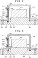
Fig. 5 is a side view showing an optical module according to a second embodiment of the present invention. -
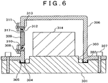
Fig. 6 is a side view showing an optical module according to a third embodiment of the present invention. - Embodiments of the present invention will be described below in detail with reference to the accompanying drawings.
- A first embodiment will be described with reference to
Fig. 4. Fig. 4 is a side view showing an optical module according to the first embodiment. Note that theMEMS mirror 204, thelaser diode 203, and theRGB combining mirror 205 shown inFig. 3 are collectively illustrated asoptical components 314. The Peltierelement 206 and the lenses are not illustrated. - In the first embodiment in
Fig. 4 , astep 303 to dispose anO ring 302 on a peripheral portion of a pedestal 301 (base) is formed. Thestep 303 preferably has a height larger than a diameter of theO ring 302. This is because, in positioning performed with ascrew 307 and a module cover 306 (will be described later), when theO ring 302 is transformed with pressure to partially enter the inside of thestep 303, the airtightness is deteriorated. For this reason, the step having a height larger than the diameter of theO ring 302 is used to make it possible to prevent theO ring 302 from taking over thestep 303. For example, a structure is desirably designed such that the thickness of an O ring and the height of a step are set to a diameter of 2 mmΦ and 3 mm, respectively. As a material of the O ring, a fluorocarbon resin, a styrene resin, or the like can be used. - A
groove 305 to apply aliquid seal material 304 is formed in an outer peripheral portion of thestep 303. As a source material of the liquid seal material, an olefine or silicon resin or the like can be used. Furthermore, an ultraviolet-curing resin may also be used. In this case, since the material is hardened by irradiating an ultraviolet ray thereon, a curing time is short. For this reason, this can contribute to improvement in manufacturing tact. In the first and second embodiments, thegroove 305 has a recessed shape, and has a U-shaped space by inserting themodule cover 306 into thegroove 305. More specifically, the liquid seal material is formed to have a U shape. - Although the
step 303 is not illustrated here, thestep 303 has a rectangular shape. The rectangular orsquare step 303 can be easily manufactured and processed. Thestep 303 need only have a shape on which theoptical components 314 can be mounted, and thestep 303 may be circular or elliptic. In this case, theO ring 302 has no corner portion to advantageously prevent even the transformed O ring from being strongly transformed at the corner portion. In addition, theO ring 303 need not be processed to form a corner portion therein. - A method of attaching the
module cover 306 will be described here. - First, the
O ring 302 is disposed on an O-ring disposing portion 330 arranged on thepedestal 301 on which theoptical components 314 are mounted. Thereafter, theliquid seal material 304 is applied or disposed in thegroove 305. The O-ring disposing portion 330 is desirably planar. Actually, the O-ring disposing portion is nearly planar. The thickness of theO ring 302 is desirably larger than that of the O-ring disposing portion 330. The O ring is transformed by pressuring the O ring to extend in vertical directions. For this reason, the horizontal width of the transformedO ring 302 is almost equal to the width of the O-ring disposing portion. In this manner, outgas (will be described later) can be prevented or suppressed from entering theoptical components 314 side. - The
module cover 306 is disposed. Themodule cover 306 has ascrew 308, an emittingwindow 309, arubber packing 310, alid 311, awindow O ring 312, and aliquid seal material 313 which are collectively called as a window unit. In the first embodiment, a method of attaching these configurations will not be described. InFig. 4 , as the configurations of the window unit, the screws are used. However, as the window unit, a so-called permanently set window may be used, and a window need only be formed in an emitting direction of theoptical components 314. This is because thegroove 305 and themodule cover 306 can be aligned. - The configurations of the window unit such as a lid are desirably attached before the
module cover 306 is disposed. This is because, when the configurations of the window unit are attached at that time, the optical module can be easily assembled. If the configurations of the window unit are not attached, outgas (will be described later) may enter theoptical components 314 side through the window unit. - A projecting portion of the
module cover 306 is fitted in thegroove 305 of thepedestal 301 to press theliquid seal material 304 into the groove. In this case, the projecting portion of themodule cover 306 has an uneven shape corresponding to thegroove 305, and the diameter of the projecting portion of themodule cover 306 is configured to be smaller than the recessed portion of thegroove 305. This is because themodule cover 306 cannot be fitted in thegroove 305 without that relationship. When the recessed portion is excessively large, as theliquid seal material 304 to be filled in thegroove 305, a larger amount of liquid seal material is used to disadvantageously increase an amount of outgas. For this reason, the diameter of the each of the projecting portions of the uneven shape is desirably close to the size of the recessed portion as much as possible. For example, the projecting portions and the recessed portion need only have a relationship to have a gap having a diameter of 0.5 mm or more. Although the diameter is used as each of the dimensions of the uneven shape, the projecting portions need not be circular and may be square, rectangular, or triangular, widths of the projecting portions of the uneven shape are different from each other, the thicknesses of sections of the uneven shape may be different from each other, or the widths of the sections of the uneven shape may be different from each other as long as the projecting portion of themodule cover 306 can be fitted in the uneven shape, i.e., as long as the projecting portion enters the recessed portion. These components are not limited to components corresponding to each other, a combination between a conical projecting portion and a square recessed portion may be used. - The arrangements or alignments of the
optical module 306 are desirably performed in an environment containing a small moisture content. As will be described later, since a space including theoptical components 314 is closed with theliquid seal material 304 and thescrew 307, once moisture enters the space, the moisture is difficult to be removed from the space. This is because it is not assumed that the window unit and thescrew 307 are removed in maintenance or the like. - On the other hand, the
liquid seal material 304 is compressed in the direction of thickness of thepedestal 301 by fixing themodule cover 306 and thepedestal 301 to each other with, for example, thescrew 307 or the like. For this reason, the thickness of theliquid seal material 304 can be adjusted independently of the thickness of theO ring 302. With this adjustment, theO ring 302 is compressed in the radial direction of theO ring 302 by themodule cover 306 and thepedestal 301. When theO ring 302 and the disposing portion have 2 mmΦ and about 1.5 mm, respectively, theO ring 302 flattened by compression is transformed into a long narrow shape in the vertical directions. However, a part of theO ring 302 is rarely disposed on thestep 303. For this reason, since theO ring 302 is compressed between themodule cover 306 and thestep 303 to make it difficult to disperse force onto thestep 303 side, and the airtightness is improved. Thus, outgas can be suppressed from entering the optical module. - In this case, a
pedestal supporting portion 351 and a modulecover supporting portion 350 preferably face each other, and both the portions are desirably configured to be nearly planar. Although thepedestal supporting portion 351 and the modulecover supporting portion 350 have uneven shapes as long as the portions have shapes corresponding to each other, it is desired that thepedestal supporting portion 351 and the modulecover supporting portion 350 preferentially have shapes corresponding to each other to perform the alignment described above. This configuration is to improve the airtightness. Although the O ring disposing portion and the modulecover supporting portion 350 look to be at the same level inFig. 4 , the portions need not be at the same level. Between thepedestal supporting portion 350 and the modulecover supporting portion 350, a space may be formed on thegroove 305 side. This is because the space can allow generated outgas to escape. - Since moisture entering the inside of the
module cover 306 is correlated to the thickness of theliquid seal material 304, the thickness of theliquid seal material 304 is adjusted independently of the thickness of theO ring 302 to make it possible to suppress moisture from entering the inside of themodule cover 306. As described above, dew condensation can be prevented from occurring on theoptical components 314 and the emittingwindow 309. - When the
liquid seal material 304 is thermally hardened and after theliquid seal material 304 is hardened, outgas normally containing an organic component is generated. When the outgas components adhere to theoptical components 314, for example, the MEMS mirror, the RGB combining mirror, the lens, the laser diode, the emittingwindow 309, and the like, a defect such as an out-of-focus projection video image obtained by the optical module may occur. - For this reason, the outgas is desired to be prevented from entering the inside of the
module cover 306. - In the structure according to the embodiment includes the
step 303 having theO ring 302 on the inner peripheral side of thegroove 305 to which theliquid seal material 304 is applied. TheO ring 302 is compressed in the radial direction of theO ring 302 with themodule cover 306 and thepedestal 301 to airtightly seal the inside of themodule cover 306 from the outside of themodule cover 306. The inside of themodule cover 306 is sealed as described above to make it possible to prevent outgas generated from theliquid seal material 304 from entering the inside of themodule cover 306. - By employing the structure of the first embodiment, the compression direction of the O ring and the compression direction of the liquid seal material are almost perpendicular to each other, and the thickness of the liquid seal material can be adjusted in dependently of the thickness of the O ring. For this reason, the airtightness of the package can be improved.
- Since the airtightness can be improved, moisture can be prevented from entering the inside of the module.
- The optical module is used in a video output device which projects a video image on a windshield for, in addition to an automobile, a railway car, an aircraft, or the like.
- A second embodiment will be described below with reference to
Fig. 5. Fig. 5 is a side view showing an optical module according to the second embodiment. TheMEMS mirror 204, thelaser diode 203, and theRGB combining mirror 205 which are shown inFig. 3 are collectively illustrated as theoptical components 314. ThePeltier element 206 and the lens are not illustrated. - In the second embodiment, in addition to the
constituent elements 301 to 314 according to the first embodiment shown inFig. 4 , an L-shaped O-ringtorsion prevention stopper 315 is disposed on the outer peripheral side of thestep 303 formed on thepedestal 301. Furthermore, an O-ringtorsion prevention stopper 316 is disposed on the outer peripheral side of astep 317 of the emittingwindow 309. The O-ringtorsion prevention stopper 316 is not always required. This is because, as described in the first embodiment, when the window is configured by a so-called permanently set window or a window fixed with an adhesive agent, the embodiment can be achieved without using the stopper. - When the
module cover 306 is fitted on the outer peripheral side of theO ring 302 by using the O-ringtorsion prevention stopper 315, theO ring 302 can be prevented from being twisted to prevent the airtightness between themodule cover 306 and thepedestal 301 from being deteriorated. - The O-ring
torsion prevention stopper 316 disposed on the outer peripheral side of thestep 317 disposed on the emittingwindow 309, like the O-ringtorsion prevention stopper 315, prevents thewindow O ring 312 from being twisted to make it possible to suppress the airtightness between themodule cover 306 and thepedestal 301 from being deteriorated. - A method of making a package structure for optical module is as follows. First, the O ring
torsion prevention stopper 315 is fitted on the outer peripheral side of thestep 303. TheO ring 302 is fitted on the outer peripheral side of the O-ringtorsion prevention stopper 315. The O-ringtorsion prevention stopper 316 is fitted on the outer peripheral portion of thestep 317 of the emittingwindow 309, and thewindow O ring 312 is fitted on the outer peripheral portion of the O-ringtorsion prevention stopper 316. It is supposed that the window O ring has about 1 mmΦ. - The
liquid seal material 304 is applied to thegroove 305 formed in thepedestal 301. Thereafter, themodule cover 306 and thepedestal 301 are fitted to each other (combination or insertion), and thepedestal 301 and themodule cover 306 are combined to each other by using, for example, thescrews liquid seal material 313 is applied to a position of themodule cover 306 where the emittingwindow 309 is fitted, the emittingwindow 309 is fitted in themodule cover 306. Thereafter, by using thescrew 308, the rubber packing 310 and thelid 311 are fitted on the outer peripheral portion of the emitting window. - A third embodiment will be described below with reference to
Fig. 6. Fig. 6 is a side view of an optical module according to the third embodiment. TheMEMS mirror 204, thelaser diode 203, and theRGB combining mirror 205 shown inFig. 3 are collectively illustrated as theoptical components 314. ThePeltier element 206 and the lens are not illustrated. - In the third embodiment, of the
constituent elements 301 to 314 according to the first embodiment shown inFig. 4 , thepedestal 301, themodule cover 306, and the emittingwindow 309 are different in shape from those in the first embodiment. - In the first embodiment, the
groove 305 and thestep 303 are formed in thepedestal 301. Thesteps 317 are formed at two positions of the emittingwindow 309. Because of the complex shape, difficulty of processing disadvantageously increases, and processing costs may increase. - On the other hand, in the third embodiment, the
pedestal 301 has no step, thegroove 305 is formed to have an L shape, and thestep 317 is formed at one position of the emittingwindow 309. For this reason, in comparison with the first embodiment, processing can be easily performed, and a shape which can easily decrease processing costs is achieved. Thegroove 305 has an L shape, and the projecting portion of themodule cover 306 is combined to the L shape to form the space of thegroove 305 into an L shape. For this reason, the sealedliquid seal material 304 has an L shape. - A method of making a package structure for an optical module according to the third embodiment is as follows. First, the
O ring 302 is fitted on the outer peripheral side of thestep 303. TheO ring 312 is fitted on the outer peripheral portion of thestep 317 of the emittingwindow 309. Theliquid seal material 304 is applied to the outer peripheral side of theO ring 302 in thegroove 305 formed in thepedestal 301. Thereafter, themodule cover 306 is fitted on thepedestal 301, and thepedestal 301 and themodule cover 306 are combined to each other by using, for example, thescrews liquid seal material 313 is applied to a position of themodule cover 306 where the emittingwindow 309 is fitted, and the emittingwindow 309 is fitted in themodule cover 306. Thereafter, the rubber packing 310 and thelid 311 are fitted on the outer peripheral portion of the emitting window by using thescrew 308. The assembling must be performed in a low-humidity environment. For example, the assembling is performed in a dry-air or nitrogen-gas atmosphere or the like. - As in the second embodiment, the L-shaped O-ring
torsion prevention stopper 315 may also be used. In this case, theO ring 302 to be compressed and transformed can be prevented from being twisted, and the airtightness can be prevented from be deteriorated. - As described above, in each of the embodiments, the compression direction of the O ring and the compression direction of the liquid seal are almost perpendicular to each other, and the thickness of the liquid seal material can be adjusted independently adjusted independently of the thickness of the O ring. For this reason, the airtightness of the package can be improved.
- Since the airtightness is improved, moisture can be prevented from entering the inside of the module.
- The present invented by the present inventor has been concretely described above on the basis of the embodiments. However, the present invention is not limited to the embodiments, and various changes and modifications can be effected without departing from the scope of the invention as a matter of course.
Claims (13)
- An optical module comprising:optical components (314) including a light source;a pedestal (301) on which the optical components (314) are mounted;a cover (306) which is combined to the pedestal (301) to seal the optical components (314); andan emitting window (309) disposed in the cover (306) to take light from the light source to outside,wherein the pedestal (301) and the cover (306) are sealed with an O ring (302) and a liquid seal material (304),characterised in thatthe pedestal (301) includes a step (303) to dispose the O ring (302) and a groove (305) in which the liquid seal material (304) is applied on an outer peripheral side of the step (303) and in which the cover (306) is fitted,the step (303) has the O ring (302) on the inner peripheral side of the groove (305) to which the liquid seal material (304) is applied,the O ring (302) is compressed in the radial direction of the O ring (302) with the cover (306) and the pedestal (301) to airtightly seal the inside of the cover (306) from the outside of the cover (306),the inside of the cover (306) is sealed to make it possible to prevent outgas generated from the liquid seal material (304) from entering the inside of the cover (306), andthe sealing is performed such that a compression direction of the O ring (302) and a compression direction of the liquid seal material (304) are almost perpendicular to each other, and the thickness of the liquid seal material (304) can be adjusted independently of the thickness of the O ring (302).
- The optical module according to claim 1, wherein the step (303) has a height larger than a diameter of the O ring (302).
- The optical module according to any preceding claim, adapted to adjust the liquid seal material (304) in thickness by striking the pedestal (301) to a planar portion formed on the outer peripheral portion of the cover (306).
- The optical module according to claim 3, comprising a screw (307) for fixing the cover (306) to the pedestal (301) in order to adjust the thickness of the liquid seal material (304).
- The optical module according to any preceding claim, wherein the cover (306) and the emitting window (309) are sealed with another O ring (312) and another liquid seal material (313) such that the compression direction of the another O ring (312) and the compression direction of the another liquid seal material (313) are almost perpendicular to each other.
- The optical module according to claim 5, wherein the emitting window (309) has a step (317) to dispose the another O ring (312) and a planar portion to cause the emitting window (309) to adhere to the cover (306) with the another liquid seal material (313).
- The optical module according to any preceding claim, wherein an O-ring torsion prevention stopper (315, 316) is disposed between the pedestal (301) and the O ring (302, 312).
- The optical module according to any preceding claim, wherein the O ring (302) is disposed in the groove (305) to apply the liquid seal material (304) on an outer peripheral portion of the O ring (302).
- The optical module according to any preceding claim, wherein a cooling Peltier element is attached.
- A method of making an optical module including optical components (314) including a light source, a pedestal (301) on which the optical components (314) are mounted, a cover (306) which is combined to the pedestal (301) to seal the optical components (314), and an emitting window (309) disposed in the cover (306) to take light from the light source to outside, comprising the steps of:preparing a pedestal (301) having a step portion (303) to dispose an O ring (302) thereon and a groove (305) in which a liquid seal material (304) is applied on an outer peripheral side of the step portion (303) to fit the cover (306) in the groove (305);disposing the O ring (302) on the step portion (303) on the inner peripheral side of the groove (305) to which the liquid seal material (304) is to be applied;applying or disposing the liquid seal material (304) in the groove (305); andfitting the cover (306) in the groove (305) to press the liquid seal material (304) into the groove (305),whereinthe O ring (302) is compressed in the radial direction of the O ring (302) with the cover (306) and the pedestal (301) to airtightly seal the inside of the cover (306) from the outside of the cover (306),the inside of the cover (306) is sealed to make it possible to prevent outgas generated from the liquid seal material (304) from entering the inside of the cover (306), andthe sealing is performed such that a compression direction of the O ring (302) and a compression direction of the liquid seal material (304) are almost perpendicular to each other, and the thickness of the liquid seal material (304) can be adjusted independently of the thickness of the O ring (302).
- The method of making an optical module according to claim 10, further comprising the step of adjusting the thickness of the liquid seal material (304) by adjusting a screw (307) to fix the cover (306) to the pedestal (301).
- The method of making an optical module according to claim 10 or 11, further comprising the step of
fitting an O-ring torsion prevention stopper (315) on an outer peripheral side of the step portion (303). - The method of making an optical module according to any of claims 10 to 12, further comprising the step of
thermally hardening the liquid seal material (304).
Applications Claiming Priority (1)
| Application Number | Priority Date | Filing Date | Title |
|---|---|---|---|
| JP2014157554A JP6356526B2 (en) | 2014-08-01 | 2014-08-01 | Optical module and manufacturing method thereof |
Publications (2)
| Publication Number | Publication Date |
|---|---|
| EP2980872A1 EP2980872A1 (en) | 2016-02-03 |
| EP2980872B1 true EP2980872B1 (en) | 2017-01-25 |
Family
ID=53510557
Family Applications (1)
| Application Number | Title | Priority Date | Filing Date |
|---|---|---|---|
| EP15001923.0A Not-in-force EP2980872B1 (en) | 2014-08-01 | 2015-06-29 | Optical module and method of making the same |
Country Status (4)
| Country | Link |
|---|---|
| US (1) | US10371369B2 (en) |
| EP (1) | EP2980872B1 (en) |
| JP (1) | JP6356526B2 (en) |
| CN (1) | CN105319808B (en) |
Families Citing this family (16)
| Publication number | Priority date | Publication date | Assignee | Title |
|---|---|---|---|---|
| JP6701751B2 (en) * | 2016-01-20 | 2020-05-27 | セイコーエプソン株式会社 | Light source device and projector |
| JP6722474B2 (en) * | 2016-03-09 | 2020-07-15 | フォトンリサーチ株式会社 | Multi-wavelength laser light source module and multi-wavelength laser light source module with multiplexer |
| CA3022421C (en) * | 2016-04-26 | 2020-10-13 | Ampthink | Enclosure for electronic components |
| CN108169989A (en) * | 2016-12-07 | 2018-06-15 | 深圳市光峰光电技术有限公司 | The optics module and projection device of sealing structure |
| JP6866261B2 (en) | 2017-08-30 | 2021-04-28 | 日立Astemo株式会社 | Seal structure |
| EP3692302B1 (en) * | 2017-10-06 | 2026-04-22 | Zodiac Pool Systems LLC | Lighting assemblies principally for swimming pools and spas |
| CN109901350A (en) * | 2017-12-08 | 2019-06-18 | 深圳光峰科技股份有限公司 | Laser equipment and projection equipment |
| WO2019174162A1 (en) * | 2018-03-16 | 2019-09-19 | 青岛海信激光显示股份有限公司 | Laser projection device |
| CN111989603B (en) * | 2018-05-23 | 2023-04-04 | 松下知识产权经营株式会社 | Resin component holding member, image display device, and light diffusion member |
| JP7172890B2 (en) * | 2019-07-11 | 2022-11-16 | 住友電気工業株式会社 | optical module |
| US11622460B2 (en) * | 2019-10-23 | 2023-04-04 | Advanced Illumination, Inc. | Hermetic fastener-less enclosures and methods of sealing the same |
| JP2021076644A (en) * | 2019-11-06 | 2021-05-20 | 株式会社日立エルジーデータストレージ | Optical module and method for sealing the same |
| JP7569622B2 (en) | 2019-11-21 | 2024-10-18 | 浜松ホトニクス株式会社 | Mirror Unit |
| US20220404614A1 (en) * | 2019-11-21 | 2022-12-22 | Hamamatsu Photonics K.K. | Mirror unit |
| CN113131332A (en) * | 2019-12-31 | 2021-07-16 | 深圳市中光工业技术研究院 | Laser device |
| CN113867084A (en) * | 2021-11-01 | 2021-12-31 | 上海芯龙光电科技股份有限公司 | Waterproof projector |
Family Cites Families (24)
| Publication number | Priority date | Publication date | Assignee | Title |
|---|---|---|---|---|
| JPS58175655U (en) * | 1982-05-19 | 1983-11-24 | キヤノン株式会社 | laser unit |
| JPS5994891A (en) * | 1982-11-24 | 1984-05-31 | Hitachi Ltd | Semiconductor laser device |
| JPS61174766A (en) * | 1985-01-30 | 1986-08-06 | Toshiba Corp | Solid image pickup device and manufacture thereof |
| JP2000252576A (en) * | 1999-03-03 | 2000-09-14 | Fuji Photo Film Co Ltd | Semiconductor laser |
| JP3697966B2 (en) * | 1999-09-17 | 2005-09-21 | 株式会社デンソー | Case of electronic control equipment |
| US6407925B1 (en) | 1999-09-17 | 2002-06-18 | Denso Corporation | Casing for electronic control devices |
| JP2002026538A (en) * | 2000-07-06 | 2002-01-25 | Fujitsu Ten Ltd | Structure of air-tight case |
| JP3468230B2 (en) | 2001-06-27 | 2003-11-17 | 株式会社ノーリツ | Bathroom heater |
| US20040100793A1 (en) * | 2002-11-22 | 2004-05-27 | Multi-Media Electronics, Inc. | Outdoor strobe light |
| JP2004253638A (en) * | 2003-02-20 | 2004-09-09 | Matsushita Electric Ind Co Ltd | Optical component and its manufacturing method |
| JP2005038956A (en) * | 2003-07-17 | 2005-02-10 | Matsushita Electric Ind Co Ltd | Optical component and manufacturing method thereof |
| DE102006020648B4 (en) * | 2006-05-02 | 2020-06-10 | Oerlikon Trading Ag, Trübbach | Process for producing a color wheel |
| JP2008282965A (en) * | 2007-05-10 | 2008-11-20 | Sony Corp | Semiconductor laser module and housing |
| JP5311779B2 (en) * | 2007-08-21 | 2013-10-09 | シチズン電子株式会社 | LED light emitting device |
| US8033687B2 (en) * | 2009-06-26 | 2011-10-11 | Pyroswift Holding Co., Limited | Waterproof assembly of LED lamp cup |
| JP2011086817A (en) * | 2009-10-16 | 2011-04-28 | Kaneka Corp | Waterproofing method of compact portable electronic apparatus and waterproof type compact portable electronic apparatus obtained by the same method |
| JP2011239099A (en) * | 2010-05-07 | 2011-11-24 | Nec Casio Mobile Communications Ltd | Waterproof apparatus and electronic equipment |
| US20120033696A1 (en) * | 2010-08-04 | 2012-02-09 | Sanyo Electric Co., Ltd. | Semiconductor laser apparatus and optical apparatus |
| TWI477882B (en) * | 2012-05-04 | 2015-03-21 | Young Optics Inc | Projection device and light valve module thereof |
| US8444283B1 (en) * | 2012-10-18 | 2013-05-21 | Steven Miller | Systems and methods for underwater lighting |
| JP6058350B2 (en) * | 2012-10-25 | 2017-01-11 | 京セラ株式会社 | Waterproof structure of the housing containing electronic components |
| WO2014113687A1 (en) * | 2013-01-18 | 2014-07-24 | LIEN, Ai-li | In-grade and under-water light fixture housing made of ceramic material |
| JP2014194504A (en) * | 2013-03-29 | 2014-10-09 | Funai Electric Co Ltd | Projector and head-up display device |
| KR101324700B1 (en) * | 2013-04-09 | 2013-11-05 | 주식회사 이지엠테크 | A double-sealed led flood light and the sealing method |
-
2014
- 2014-08-01 JP JP2014157554A patent/JP6356526B2/en not_active Expired - Fee Related
-
2015
- 2015-06-29 EP EP15001923.0A patent/EP2980872B1/en not_active Not-in-force
- 2015-07-10 CN CN201510404541.5A patent/CN105319808B/en not_active Expired - Fee Related
- 2015-07-10 US US14/796,890 patent/US10371369B2/en active Active
Non-Patent Citations (1)
| Title |
|---|
| None * |
Also Published As
| Publication number | Publication date |
|---|---|
| JP2016035491A (en) | 2016-03-17 |
| US20160033122A1 (en) | 2016-02-04 |
| CN105319808B (en) | 2017-04-12 |
| CN105319808A (en) | 2016-02-10 |
| US10371369B2 (en) | 2019-08-06 |
| JP6356526B2 (en) | 2018-07-11 |
| EP2980872A1 (en) | 2016-02-03 |
Similar Documents
| Publication | Publication Date | Title |
|---|---|---|
| US10371369B2 (en) | Sealing of optical module with O-ring and liquid resin | |
| JP3924054B2 (en) | LCD projector | |
| US8699115B2 (en) | Production method for a micromechanical component, and a micromechanical component | |
| US7023504B2 (en) | Electro-optical device encased in mounting case, projection display apparatus, and mounting case | |
| JP5104694B2 (en) | Head-up display device | |
| US11307377B2 (en) | Light source device, projector and lighting device | |
| US20160282609A1 (en) | Electro-optical device, manufacturing method thereof, and electronic apparatus | |
| JP2002006282A (en) | Liquid crystal display | |
| CN106660781B (en) | For the assembly of micromirror chip, mirroring apparatus and for the manufacturing method of mirroring apparatus | |
| CN101323428A (en) | Patterned contact sheet for protecting critical surfaces during fabrication | |
| CN100526975C (en) | Optical devices and projectors | |
| US20110249449A1 (en) | Optical semiconductor device module | |
| KR100614724B1 (en) | Electro-optical device encased in mounting case, projection display apparatus, and mounting case | |
| JP2018018034A (en) | Scanning display device | |
| CN103676289B (en) | Liquid crystal display device | |
| JP2000227768A (en) | Electro-optical panel, electro-optical panel module, and projection display device | |
| JP2005292238A (en) | Polarizing plate, display device using the same, and manufacturing method thereof | |
| JP2008191360A (en) | Mounting case, electro-optical device, and electronic apparatus | |
| US20210131659A1 (en) | Optical module and sealing method thereon | |
| KR20050077020A (en) | Liquid crystal display device and video camera | |
| KR20130057090A (en) | Camera module | |
| JP2006041185A (en) | Dustproof structure for electronic equipment | |
| JP2007206723A (en) | Electro-optical panel, electro-optical panel module, and projection display device | |
| JP3797163B2 (en) | projector | |
| JP2005250506A (en) | Electro-optical device and projection display device including the same |
Legal Events
| Date | Code | Title | Description |
|---|---|---|---|
| PUAI | Public reference made under article 153(3) epc to a published international application that has entered the european phase |
Free format text: ORIGINAL CODE: 0009012 |
|
| 17P | Request for examination filed |
Effective date: 20151029 |
|
| AK | Designated contracting states |
Kind code of ref document: A1 Designated state(s): AL AT BE BG CH CY CZ DE DK EE ES FI FR GB GR HR HU IE IS IT LI LT LU LV MC MK MT NL NO PL PT RO RS SE SI SK SM TR |
|
| AX | Request for extension of the european patent |
Extension state: BA ME |
|
| RBV | Designated contracting states (corrected) |
Designated state(s): AL AT BE BG CH CY CZ DE DK EE ES FI FR GB GR HR HU IE IS IT LI LT LU LV MC MK MT NL NO PL PT RO RS SE SI SK SM TR |
|
| REG | Reference to a national code |
Ref country code: DE Ref legal event code: R079 Ref document number: 602015001291 Country of ref document: DE Free format text: PREVIOUS MAIN CLASS: H01L0033640000 Ipc: G03B0021200000 |
|
| GRAP | Despatch of communication of intention to grant a patent |
Free format text: ORIGINAL CODE: EPIDOSNIGR1 |
|
| RIC1 | Information provided on ipc code assigned before grant |
Ipc: H01L 33/64 20100101ALI20160630BHEP Ipc: G03B 21/20 20060101AFI20160630BHEP |
|
| INTG | Intention to grant announced |
Effective date: 20160729 |
|
| STAA | Information on the status of an ep patent application or granted ep patent |
Free format text: STATUS: GRANT OF PATENT IS INTENDED |
|
| GRAS | Grant fee paid |
Free format text: ORIGINAL CODE: EPIDOSNIGR3 |
|
| GRAA | (expected) grant |
Free format text: ORIGINAL CODE: 0009210 |
|
| STAA | Information on the status of an ep patent application or granted ep patent |
Free format text: STATUS: THE PATENT HAS BEEN GRANTED |
|
| AK | Designated contracting states |
Kind code of ref document: B1 Designated state(s): AL AT BE BG CH CY CZ DE DK EE ES FI FR GB GR HR HU IE IS IT LI LT LU LV MC MK MT NL NO PL PT RO RS SE SI SK SM TR |
|
| REG | Reference to a national code |
Ref country code: GB Ref legal event code: FG4D |
|
| REG | Reference to a national code |
Ref country code: CH Ref legal event code: EP |
|
| REG | Reference to a national code |
Ref country code: AT Ref legal event code: REF Ref document number: 864471 Country of ref document: AT Kind code of ref document: T Effective date: 20170215 |
|
| REG | Reference to a national code |
Ref country code: IE Ref legal event code: FG4D |
|
| REG | Reference to a national code |
Ref country code: DE Ref legal event code: R096 Ref document number: 602015001291 Country of ref document: DE |
|
| REG | Reference to a national code |
Ref country code: LT Ref legal event code: MG4D |
|
| REG | Reference to a national code |
Ref country code: NL Ref legal event code: MP Effective date: 20170125 |
|
| REG | Reference to a national code |
Ref country code: AT Ref legal event code: MK05 Ref document number: 864471 Country of ref document: AT Kind code of ref document: T Effective date: 20170125 |
|
| PG25 | Lapsed in a contracting state [announced via postgrant information from national office to epo] |
Ref country code: NL Free format text: LAPSE BECAUSE OF FAILURE TO SUBMIT A TRANSLATION OF THE DESCRIPTION OR TO PAY THE FEE WITHIN THE PRESCRIBED TIME-LIMIT Effective date: 20170125 |
|
| PG25 | Lapsed in a contracting state [announced via postgrant information from national office to epo] |
Ref country code: LT Free format text: LAPSE BECAUSE OF FAILURE TO SUBMIT A TRANSLATION OF THE DESCRIPTION OR TO PAY THE FEE WITHIN THE PRESCRIBED TIME-LIMIT Effective date: 20170125 Ref country code: IS Free format text: LAPSE BECAUSE OF FAILURE TO SUBMIT A TRANSLATION OF THE DESCRIPTION OR TO PAY THE FEE WITHIN THE PRESCRIBED TIME-LIMIT Effective date: 20170525 Ref country code: GR Free format text: LAPSE BECAUSE OF FAILURE TO SUBMIT A TRANSLATION OF THE DESCRIPTION OR TO PAY THE FEE WITHIN THE PRESCRIBED TIME-LIMIT Effective date: 20170426 Ref country code: NO Free format text: LAPSE BECAUSE OF FAILURE TO SUBMIT A TRANSLATION OF THE DESCRIPTION OR TO PAY THE FEE WITHIN THE PRESCRIBED TIME-LIMIT Effective date: 20170425 Ref country code: FI Free format text: LAPSE BECAUSE OF FAILURE TO SUBMIT A TRANSLATION OF THE DESCRIPTION OR TO PAY THE FEE WITHIN THE PRESCRIBED TIME-LIMIT Effective date: 20170125 Ref country code: HR Free format text: LAPSE BECAUSE OF FAILURE TO SUBMIT A TRANSLATION OF THE DESCRIPTION OR TO PAY THE FEE WITHIN THE PRESCRIBED TIME-LIMIT Effective date: 20170125 |
|
| PG25 | Lapsed in a contracting state [announced via postgrant information from national office to epo] |
Ref country code: PL Free format text: LAPSE BECAUSE OF FAILURE TO SUBMIT A TRANSLATION OF THE DESCRIPTION OR TO PAY THE FEE WITHIN THE PRESCRIBED TIME-LIMIT Effective date: 20170125 Ref country code: PT Free format text: LAPSE BECAUSE OF FAILURE TO SUBMIT A TRANSLATION OF THE DESCRIPTION OR TO PAY THE FEE WITHIN THE PRESCRIBED TIME-LIMIT Effective date: 20170525 Ref country code: BG Free format text: LAPSE BECAUSE OF FAILURE TO SUBMIT A TRANSLATION OF THE DESCRIPTION OR TO PAY THE FEE WITHIN THE PRESCRIBED TIME-LIMIT Effective date: 20170425 Ref country code: ES Free format text: LAPSE BECAUSE OF FAILURE TO SUBMIT A TRANSLATION OF THE DESCRIPTION OR TO PAY THE FEE WITHIN THE PRESCRIBED TIME-LIMIT Effective date: 20170125 Ref country code: SE Free format text: LAPSE BECAUSE OF FAILURE TO SUBMIT A TRANSLATION OF THE DESCRIPTION OR TO PAY THE FEE WITHIN THE PRESCRIBED TIME-LIMIT Effective date: 20170125 Ref country code: LV Free format text: LAPSE BECAUSE OF FAILURE TO SUBMIT A TRANSLATION OF THE DESCRIPTION OR TO PAY THE FEE WITHIN THE PRESCRIBED TIME-LIMIT Effective date: 20170125 Ref country code: RS Free format text: LAPSE BECAUSE OF FAILURE TO SUBMIT A TRANSLATION OF THE DESCRIPTION OR TO PAY THE FEE WITHIN THE PRESCRIBED TIME-LIMIT Effective date: 20170125 Ref country code: AT Free format text: LAPSE BECAUSE OF FAILURE TO SUBMIT A TRANSLATION OF THE DESCRIPTION OR TO PAY THE FEE WITHIN THE PRESCRIBED TIME-LIMIT Effective date: 20170125 |
|
| REG | Reference to a national code |
Ref country code: DE Ref legal event code: R097 Ref document number: 602015001291 Country of ref document: DE |
|
| PG25 | Lapsed in a contracting state [announced via postgrant information from national office to epo] |
Ref country code: SK Free format text: LAPSE BECAUSE OF FAILURE TO SUBMIT A TRANSLATION OF THE DESCRIPTION OR TO PAY THE FEE WITHIN THE PRESCRIBED TIME-LIMIT Effective date: 20170125 Ref country code: CZ Free format text: LAPSE BECAUSE OF FAILURE TO SUBMIT A TRANSLATION OF THE DESCRIPTION OR TO PAY THE FEE WITHIN THE PRESCRIBED TIME-LIMIT Effective date: 20170125 Ref country code: RO Free format text: LAPSE BECAUSE OF FAILURE TO SUBMIT A TRANSLATION OF THE DESCRIPTION OR TO PAY THE FEE WITHIN THE PRESCRIBED TIME-LIMIT Effective date: 20170125 Ref country code: EE Free format text: LAPSE BECAUSE OF FAILURE TO SUBMIT A TRANSLATION OF THE DESCRIPTION OR TO PAY THE FEE WITHIN THE PRESCRIBED TIME-LIMIT Effective date: 20170125 Ref country code: IT Free format text: LAPSE BECAUSE OF FAILURE TO SUBMIT A TRANSLATION OF THE DESCRIPTION OR TO PAY THE FEE WITHIN THE PRESCRIBED TIME-LIMIT Effective date: 20170125 |
|
| PG25 | Lapsed in a contracting state [announced via postgrant information from national office to epo] |
Ref country code: SM Free format text: LAPSE BECAUSE OF FAILURE TO SUBMIT A TRANSLATION OF THE DESCRIPTION OR TO PAY THE FEE WITHIN THE PRESCRIBED TIME-LIMIT Effective date: 20170125 Ref country code: DK Free format text: LAPSE BECAUSE OF FAILURE TO SUBMIT A TRANSLATION OF THE DESCRIPTION OR TO PAY THE FEE WITHIN THE PRESCRIBED TIME-LIMIT Effective date: 20170125 |
|
| PLBE | No opposition filed within time limit |
Free format text: ORIGINAL CODE: 0009261 |
|
| STAA | Information on the status of an ep patent application or granted ep patent |
Free format text: STATUS: NO OPPOSITION FILED WITHIN TIME LIMIT |
|
| 26N | No opposition filed |
Effective date: 20171026 |
|
| PG25 | Lapsed in a contracting state [announced via postgrant information from national office to epo] |
Ref country code: MC Free format text: LAPSE BECAUSE OF FAILURE TO SUBMIT A TRANSLATION OF THE DESCRIPTION OR TO PAY THE FEE WITHIN THE PRESCRIBED TIME-LIMIT Effective date: 20170125 |
|
| PG25 | Lapsed in a contracting state [announced via postgrant information from national office to epo] |
Ref country code: SI Free format text: LAPSE BECAUSE OF FAILURE TO SUBMIT A TRANSLATION OF THE DESCRIPTION OR TO PAY THE FEE WITHIN THE PRESCRIBED TIME-LIMIT Effective date: 20170125 |
|
| REG | Reference to a national code |
Ref country code: FR Ref legal event code: ST Effective date: 20180228 |
|
| REG | Reference to a national code |
Ref country code: IE Ref legal event code: MM4A |
|
| PG25 | Lapsed in a contracting state [announced via postgrant information from national office to epo] |
Ref country code: IE Free format text: LAPSE BECAUSE OF NON-PAYMENT OF DUE FEES Effective date: 20170629 Ref country code: LU Free format text: LAPSE BECAUSE OF NON-PAYMENT OF DUE FEES Effective date: 20170629 |
|
| REG | Reference to a national code |
Ref country code: BE Ref legal event code: MM Effective date: 20170630 |
|
| PG25 | Lapsed in a contracting state [announced via postgrant information from national office to epo] |
Ref country code: FR Free format text: LAPSE BECAUSE OF NON-PAYMENT OF DUE FEES Effective date: 20170630 |
|
| PG25 | Lapsed in a contracting state [announced via postgrant information from national office to epo] |
Ref country code: BE Free format text: LAPSE BECAUSE OF NON-PAYMENT OF DUE FEES Effective date: 20170630 |
|
| PG25 | Lapsed in a contracting state [announced via postgrant information from national office to epo] |
Ref country code: MT Free format text: LAPSE BECAUSE OF NON-PAYMENT OF DUE FEES Effective date: 20170629 |
|
| REG | Reference to a national code |
Ref country code: CH Ref legal event code: PL |
|
| PG25 | Lapsed in a contracting state [announced via postgrant information from national office to epo] |
Ref country code: LI Free format text: LAPSE BECAUSE OF NON-PAYMENT OF DUE FEES Effective date: 20180630 Ref country code: CH Free format text: LAPSE BECAUSE OF NON-PAYMENT OF DUE FEES Effective date: 20180630 |
|
| PG25 | Lapsed in a contracting state [announced via postgrant information from national office to epo] |
Ref country code: HU Free format text: LAPSE BECAUSE OF FAILURE TO SUBMIT A TRANSLATION OF THE DESCRIPTION OR TO PAY THE FEE WITHIN THE PRESCRIBED TIME-LIMIT; INVALID AB INITIO Effective date: 20150629 |
|
| PG25 | Lapsed in a contracting state [announced via postgrant information from national office to epo] |
Ref country code: CY Free format text: LAPSE BECAUSE OF FAILURE TO SUBMIT A TRANSLATION OF THE DESCRIPTION OR TO PAY THE FEE WITHIN THE PRESCRIBED TIME-LIMIT Effective date: 20170125 |
|
| PG25 | Lapsed in a contracting state [announced via postgrant information from national office to epo] |
Ref country code: MK Free format text: LAPSE BECAUSE OF FAILURE TO SUBMIT A TRANSLATION OF THE DESCRIPTION OR TO PAY THE FEE WITHIN THE PRESCRIBED TIME-LIMIT Effective date: 20170125 |
|
| GBPC | Gb: european patent ceased through non-payment of renewal fee |
Effective date: 20190629 |
|
| PG25 | Lapsed in a contracting state [announced via postgrant information from national office to epo] |
Ref country code: TR Free format text: LAPSE BECAUSE OF FAILURE TO SUBMIT A TRANSLATION OF THE DESCRIPTION OR TO PAY THE FEE WITHIN THE PRESCRIBED TIME-LIMIT Effective date: 20170125 |
|
| PG25 | Lapsed in a contracting state [announced via postgrant information from national office to epo] |
Ref country code: GB Free format text: LAPSE BECAUSE OF NON-PAYMENT OF DUE FEES Effective date: 20190629 |
|
| PG25 | Lapsed in a contracting state [announced via postgrant information from national office to epo] |
Ref country code: AL Free format text: LAPSE BECAUSE OF FAILURE TO SUBMIT A TRANSLATION OF THE DESCRIPTION OR TO PAY THE FEE WITHIN THE PRESCRIBED TIME-LIMIT Effective date: 20170125 |
|
| PGFP | Annual fee paid to national office [announced via postgrant information from national office to epo] |
Ref country code: DE Payment date: 20230502 Year of fee payment: 9 |
|
| REG | Reference to a national code |
Ref country code: DE Ref legal event code: R119 Ref document number: 602015001291 Country of ref document: DE |
|
| PG25 | Lapsed in a contracting state [announced via postgrant information from national office to epo] |
Ref country code: DE Free format text: LAPSE BECAUSE OF NON-PAYMENT OF DUE FEES Effective date: 20250101 |