EP2980597B1 - Current transducer with fluxgate detector - Google Patents
Current transducer with fluxgate detector Download PDFInfo
- Publication number
- EP2980597B1 EP2980597B1 EP14179204.4A EP14179204A EP2980597B1 EP 2980597 B1 EP2980597 B1 EP 2980597B1 EP 14179204 A EP14179204 A EP 14179204A EP 2980597 B1 EP2980597 B1 EP 2980597B1
- Authority
- EP
- European Patent Office
- Prior art keywords
- fluxgate
- coil
- current
- current transducer
- excitation voltage
- Prior art date
- Legal status (The legal status is an assumption and is not a legal conclusion. Google has not performed a legal analysis and makes no representation as to the accuracy of the status listed.)
- Active
Links
Images


Classifications
-
- G—PHYSICS
- G01—MEASURING; TESTING
- G01R—MEASURING ELECTRIC VARIABLES; MEASURING MAGNETIC VARIABLES
- G01R15/00—Details of measuring arrangements of the types provided for in groups G01R17/00 - G01R29/00, G01R33/00 - G01R33/26 or G01R35/00
- G01R15/14—Adaptations providing voltage or current isolation, e.g. for high-voltage or high-current networks
- G01R15/18—Adaptations providing voltage or current isolation, e.g. for high-voltage or high-current networks using inductive devices, e.g. transformers
- G01R15/183—Adaptations providing voltage or current isolation, e.g. for high-voltage or high-current networks using inductive devices, e.g. transformers using transformers with a magnetic core
- G01R15/185—Adaptations providing voltage or current isolation, e.g. for high-voltage or high-current networks using inductive devices, e.g. transformers using transformers with a magnetic core with compensation or feedback windings or interacting coils, e.g. 0-flux sensors
-
- G—PHYSICS
- G01—MEASURING; TESTING
- G01R—MEASURING ELECTRIC VARIABLES; MEASURING MAGNETIC VARIABLES
- G01R33/00—Arrangements or instruments for measuring magnetic variables
- G01R33/02—Measuring direction or magnitude of magnetic fields or magnetic flux
- G01R33/04—Measuring direction or magnitude of magnetic fields or magnetic flux using the flux-gate principle
-
- H—ELECTRICITY
- H01—ELECTRIC ELEMENTS
- H01F—MAGNETS; INDUCTANCES; TRANSFORMERS; SELECTION OF MATERIALS FOR THEIR MAGNETIC PROPERTIES
- H01F38/00—Adaptations of transformers or inductances for specific applications or functions
- H01F38/20—Instruments transformers
- H01F38/22—Instruments transformers for single phase AC
- H01F38/28—Current transformers
- H01F38/30—Constructions
-
- H—ELECTRICITY
- H01—ELECTRIC ELEMENTS
- H01F—MAGNETS; INDUCTANCES; TRANSFORMERS; SELECTION OF MATERIALS FOR THEIR MAGNETIC PROPERTIES
- H01F38/00—Adaptations of transformers or inductances for specific applications or functions
- H01F38/20—Instruments transformers
- H01F38/22—Instruments transformers for single phase AC
- H01F38/28—Current transformers
- H01F38/32—Circuit arrangements
-
- G—PHYSICS
- G01—MEASURING; TESTING
- G01R—MEASURING ELECTRIC VARIABLES; MEASURING MAGNETIC VARIABLES
- G01R1/00—Details of instruments or arrangements of the types included in groups G01R5/00 - G01R13/00 and G01R31/00
-
- G—PHYSICS
- G01—MEASURING; TESTING
- G01R—MEASURING ELECTRIC VARIABLES; MEASURING MAGNETIC VARIABLES
- G01R19/00—Arrangements for measuring currents or voltages or for indicating presence or sign thereof
- G01R19/0092—Measuring current only
-
- G—PHYSICS
- G01—MEASURING; TESTING
- G01R—MEASURING ELECTRIC VARIABLES; MEASURING MAGNETIC VARIABLES
- G01R33/00—Arrangements or instruments for measuring magnetic variables
- G01R33/0023—Electronic aspects, e.g. circuits for stimulation, evaluation, control; Treating the measured signals; calibration
-
- H—ELECTRICITY
- H01—ELECTRIC ELEMENTS
- H01F—MAGNETS; INDUCTANCES; TRANSFORMERS; SELECTION OF MATERIALS FOR THEIR MAGNETIC PROPERTIES
- H01F38/00—Adaptations of transformers or inductances for specific applications or functions
- H01F38/20—Instruments transformers
- H01F38/22—Instruments transformers for single phase AC
- H01F38/28—Current transformers
- H01F38/30—Constructions
- H01F2038/305—Constructions with toroidal magnetic core
-
- H—ELECTRICITY
- H02—GENERATION; CONVERSION OR DISTRIBUTION OF ELECTRIC POWER
- H02P—CONTROL OR REGULATION OF ELECTRIC MOTORS, ELECTRIC GENERATORS OR DYNAMO-ELECTRIC CONVERTERS; CONTROLLING TRANSFORMERS, REACTORS OR CHOKE COILS
- H02P1/00—Arrangements for starting electric motors or dynamo-electric converters
Definitions
- the present invention relates to an electric current transducer comprising a fluxgate magnetic field detector for measuring a current flowing in a primary conductor.
- One of the most common ways of measuring a current flowing in a primary conductor is by detecting the magnetic field generated by the current.
- Electrical current transducer modules for current sensing applications may have different configurations depending on various parameters such as the current measurement range, required accuracy, insensitivity to noise, compactness, manufacturing costs, frequency range and others.
- a magnetic field detector In current transducers of the open-loop type, a magnetic field detector generates an image of the current to be measured that represents the measurement signal.
- the magnetic field detector is connected in a feed-back loop to a secondary coil that generates a compensation current that tends to cancel the magnetic field generated by the primary conductor.
- Closed-loop current transducers are generally more accurate and can employ more sensitive magnetic field detectors because of the low intensity of the magnetic field being detected in view of the compensation.
- Most sensitive and accurate magnetic field detectors are fluxgate detectors. These detectors comprise a saturable soft magnetic core surrounded by an excitation coil that is connected to an oscillation circuit that generates an alternating electrical signal configure to alternating saturate the soft magnetic core.
- a magnetic field for instance the magnetic field generated by the primary current, generates a bias on the alternating signal that can be measured by various means and that is representative of the external magnetic field.
- Some conventional fluxgate based current transducers allow for a certain level of compensation of this excitation signal so that it is reduced to a small residue in the output signal as well as in the circuit of the current to be measured. This however increases the cost of the transducer.
- EP0356248 and EP2431751 disclose examples of current sensors including a correction circuitry to cancel the effects of ripple current on the output.
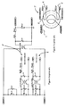
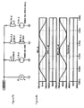
- a known fluxgate measuring head 7 illustrated in figure 1 a and 1 c of a known fluxgate based current transducer comprises a magnetic shield 8 surrounding two annular fluxgate detectors 4, 4', each made of an excitation coil 3 wound around a soft magnetic material core 5.
- a secondary coil 6 is wound around the magnetic shield.
- the voltage characteristic of the excitation signal of the fluxgate detectors 4, 4' has an almost rectangular profile as illustrated in figure 3a .
- the excitation frequency is either determined by the excitation voltage and the saturation flux of the fluxgate so that it is self-oscillating, or synchronized to an external signal in a relatively small frequency range.
- One of the fluxgate detectors is often used for compensation of the excitation signal only.
- the advantage is that the residual ripple present on the primary side and on the secondary side of the transducer, which influences the current to be measured, is relatively low. Disadvantages however include the manufacturing cost for the second fluxgate and the high frequency noise present in primary and secondary circuits which are caused by the harmonics of the almost rectangular excitation voltage with steep edges.
- FIG. 1 b An equivalent circuit of the fluxgate measuring head illustrated in figures 1 a and 1 c is represented in figure 1 b , where :
- both fluxgate detectors 4, 4' are connected in series with the secondary main inductance Rcu_fx plus Ls_fx and the whole is connected in parallel with the primary circuit P and secondary circuit S.
- the current which must be measured, coming from the primary conductor is directly transferred to the secondary circuit by a current transformer effect.
- the current passing through the fluxgate detectors allows the secondary circuit to compensate the primary conductor ampere turns in view of the closed-loop system.
- the fluxgate detectors are generally excited with a square voltage which generates a ripple on the primary side and on the secondary circuit by and electromagnetic coupling due to the steep slopes of the excitation voltage as seen in figure 3a .
- the purpose of the second fluxgate detector is to minimize these undesirable effects.
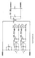
- Figure 2 represents an equivalent circuit without the second fluxgate detector 4'.
- the excitation voltage Vfx_in generates a voltage U1 by a transformer effect. This voltage is distributed on circuit portions Z2 and Z3 (the primary circuit P is open) and thus generates a voltage U3 coupled to the secondary circuit S.
- the result is a noisy current passing through the measuring resistor Rm_fx1 having a fundamental frequency same as the frequency of the excitation voltage.
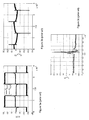
- the plots of the figures 3a-3c illustrate this effect.
- Figure 3a shows the excitation voltage Vfx_in and the voltage through the fluxgate measuring resistor Um_fx.
- Figure 3b presents a global view of the ripple voltage Um_s across the secondary measuring resistor due to the magnetic coupling between the fluxgate detector circuit and the secondary circuit.
- the peaks in figures 3b and 3c are mainly due to parasitic coupling during the excitation voltage switching. The peaks can be partially reduced by filtering provided that the bandwidth of the transducer is respected.
- the low frequency ripple may be reduced by placing a second fluxgate detector 4' into the shield 5 as shown in Figures 1 a to 1 c, and exciting it with the same voltage as the excitation voltage Vfx_in but phase shifted by 180°.
- the first fluxgate 4 is used as a detector (master) and the second fluxgate 4' is used to reduce the ripple (slave).
- the second fluxgate detector allows the partial cancellation of the ripple, the peaks are not cancelled.
- Another drawback of this known system are the high production costs.
- the problem of noise resulting from the excitation signal is not limited to the above described specific configuration and may be found in other fluxgate based transducers, especially those used in applications requiring high precision.
- An object of the invention is to provide an electrical current transducer with a fluxgate magnetic field detector that is accurate, while being compact and economical to produce and assemble.
- an electrical current transducer of a closed-loop type for measuring a primary current flowing in a primary conductor comprising a fluxgate measuring head and an electronic circuit including a microprocessor for digital signal processing.
- the measuring head includes a secondary coil, and a fluxgate detector comprising an excitation coil and a magnetic material core mounted inside the magnetic shield.
- the electronic circuit comprises an excitation coil drive circuit configured to generate an alternating excitation voltage to supply the excitation coil with an alternating excitation current.
- the secondary coil is connected in a feedback loop of the electronic circuit to the excitation coil drive circuit.
- the electronic circuit further comprises a ripple compensation circuit configured to compensate for a ripple signal generated by the alternating excitation voltage by injecting a ripple compensation signal in a coil of the measuring head.
- the ripple compensation circuit comprises a dedicated ripple compensation coil wound around a magnetic shield surrounding the fluxgate detector, or around the secondary coil, the ripple compensation signal being injected into the ripple compensation coil.
- the ripple compensation signal may be injected into the secondary coil of the measuring head.
- the ripple compensation signal may be injected into an electrostatic shielding coil of the measuring head wound around the secondary coil.
- the microprocessor comprises a controller configured to control an amplitude of the alternating excitation voltage applied across an impedance of the fluxgate detector in order to maintain a preset saturation level in the fluxgate detector.
- the amplitude control is performed by digital sampling and signal processing of the applied alternating excitation voltage and applying an increase or decrease of the amplitude of the sampled signal.
- the alternating excitation voltage is essentially in the form of a sinusoidal wave.
- the microprocessor comprises a controller configured to control an amplitude of a ripple compensation signal by digital sampling and signal processing of an alternating excitation voltage applied across an impedance of the fluxgate detector and by comparing said applied alternating excitation voltage with preset values stored in a look up table of the electronic circuit.
- preset values include three values of correspondence for the excitation voltage: at a defined reference temperature, at a defined minimum operating temperature and at a defined maximum operating temperature. Other values between preset values may advantageously be obtained by linear interpolation.
- the sinusoidal wave is generated by a digital-to-analog converter (DAC) of a microprocessor of the electronic circuit.
- DAC digital-to-analog converter
- a microprocessor of the electronic circuit comprises a Discrete Fourier Transform (DFT) module configured for digital sampling and signal processing of said applied alternating excitation voltage.
- DFT Discrete Fourier Transform
- a microprocessor of the electronic circuit comprises a Goertzel filter configured for digital sampling and signal processing of said applied alternating excitation voltage.
- a number of turns of the secondary coil is at least ten times greater than a number of turns of the ripple compensation coil.
- the electronic circuit comprises a second harmonic detection circuit configured to detect, by digital sampling and signal processing of said applied alternating excitation voltage, a second harmonic of the alternating excitation voltage applied across an impedance of the fluxgate detector, said second harmonic being used to control the secondary coil compensation current in a feedback loop.
- the measuring head has a single said fluxgate detector.
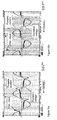
- an exemplary embodiment of an electrical current transducer 2 for measuring a primary current I P flowing in a primary conductor 1 comprises a fluxgate measuring head 7 comprising a fluxgate magnetic field detector 4 and a secondary coil 6 wound around the fluxgate magnetic field detector.
- the fluxgate magnetic field detector shall also be referred to herein as "fluxgate detector” for simplicity.
- the measuring head may further comprise a magnetic shield 8, made of a soft magnetic material with a high magnetic permeability, surrounding the fluxgate detector 4.
- the secondary coil 6 may be positioned around the magnetic shield 8.
- the magnetic shield may for instance be formed of two shell parts assembled together around the fluxgate detector, or of a magnetic material tape wound around the fluxgate detector.
- the measuring head 7 may, in relation to the above described aspects, have a similar construction to the known measuring head of figure 1 a , except that the second fluxgate detector 4' is not needed.
- the secondary coil acts as a compensation coil that is supplied with electrical current I S in a feedback loop 12 connected to the fluxgate detector 4 that seeks to cancel the magnetic field generated by a primary conductor 1 carrying the current I P to be measured, the primary conductor extending through a central passage 10 of the transducer.
- the magnetic field generated by the primary conductor 1 circulates in the magnetic shield 8 and a portion thereof is picked up by the fluxgate magnetic field detector 4 positioned inside the shield 8.
- the fluxgate magnetic field detector 4 comprises a saturable soft magnetic core 5 surrounded by an excitation coil 3 that is connected to an excitation coil drive circuit 14 that generates an alternating excitation current I fx configured to alternatingly saturate the soft magnetic core.
- the magnetic field generated by the residual current linkage ( I P ⁇ N P - I S ⁇ N S ) generates a bias on the alternating signal I fx that can be measured and that is representative of the measurement error.
- the ripple compensating function is performed by an electronic circuit 16 comprising a microprocessor 18, that may be the same, or different, as the one used for the control loop 12 to control the secondary winding 6, and a ripple compensation coil control circuit 28 connected to a ripple compensation coil 26 via a control loop 30.
- the ripple compensation coil control circuit 28 is configured to generate a ripple compensation current I R that seeks to cancel the ripple signal caused by the excitation current I fx of the fluxgate detector 4.
- the excitation voltage signal I fx for the excitation coil of the fluxgate magnetic field detector 4 is generated by the microprocessor 18 and an amplifier 20.
- the peak values of the excitation current I fx are monitored by a peak detection function 22 of the microprocessor 18 and the amplitude of the excitation signal is slowly adapted via a fluxgate control loop 24 in order to achieve essentially constant or stable peak values for the excitation current. This is useful to compensate, inter alia, for the temperature dependent saturation flux of the fluxgate.
- the shape of the excitation signal for the excitation coil of the fluxgate magnetic field detector is provided as a sine wave or an essentially sinosoidal signal.
- the aim is to have a signal with a low number of harmonics without switching.
- the simulation of Figures 5a, 5b shows different signals when the fluxgate detector is excited with a sinusoidal excitation voltage V1.
- the voltage signal Um_fx is an image of the current passing through the fluxgate current shunt Rm_fx showing a typical saturation curve of the detector.
- the voltage U_fx across the fluxgate detector V1 - Um_fx remains close to a perfect sinusoidal wave and thus, due to the coupling effect, the voltage Um_S at the output of the secondary coil remains essentially sinusoidal.
- a further step is to remove the ripple at the output of the secondary coil. This may be achieved by providing a ripple compensation coil 26 with a plurality of turns Nfxc around the secondary coil and using this ripple compensation coil 26 to inject a current I R in opposition to the phase of the ripple in order to cancel it.
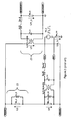
- the equivalent circuit comprising the ripple compensation circuit is shown in Figure 6 .
- FIGS. 7a and 7b simplified circuit diagrams of the equivalent circuit of the Figure 6 are shown, where figure 7a relates to the ripple compensation coil not connected, and figure 7b relates to the ripple compensation coil 26 connected, both assuming an ideal current source.
- elements such as voltage sources, current sources, inductances and resistances may be referred to the primary side.
- the mentioned values correspond to an exemplary application.
- the excitation frequency is chosen as 1 kHz.
- the current from the primary conductor will not be coupled with the ripple compensation circuit 26, 28 but with the secondary circuit 6, 13, provided that the number of secondary coil turns N_S is much larger than the number of turns Nfxc of the ripple compensation coil: N_S >> Nfxc.
- the number of secondary coil turns N_S is at least ten times greater than the number of turns Nfxc of the ripple compensation coil.
- the high frequency (HF) noise that is found in the secondary circuit output voltage signal is due to the nature of the power amplifier which in this example is a class D amplifier with for instance a switching frequency of 200 kHz.
- the ripple compensation coil is switched on, as shown in Figure 12 , the ripple disappears, whereby the remaining signal is due to the HF noise of the class D amplifier.
- the error due to the ripple represents a value greater than 100 ppm (parts per million).
- the ripple compensation circuit switched on the error value is around 5 ppm.
- the coherent noise (ripple) of the fluxgate detector excitation frequency at 1 kHz is well compensated. Due to the small distortion of the voltage Ufx across the fluxgate detector (as discussed earlier in relation to figures 5a, 5b ) the 3rd harmonic at 3 kHz is present (but could be suppressed by adding a signal of this frequency with appropriate amplitude and phase to the compensation signal).
- the excitation voltage of the fluxgate detector is a sine wave which is initially generated by a digital to analog converter (DAC) 32 of a microprocessor 18 of the current transducer. Once filtered and amplified, for instance via a push-pull output circuit, the sine wave signal is applied to the excitation coil of the fluxgate detector 4 through a capacitor in order to eliminate a possible DC (direct current) offset component which could be interpreted as a primary current by the detector.
- the voltage across the fluxgate current shunt Rm_fx which is the image of the current passing through the fluxgate detector, is sampled.
- the sampled signal comprises essentially only odd harmonics.
- the sampled signal comprises essentially only odd harmonics.
- the second harmonic is the largest, measurement of the residual current linkage is performed by extracting principally the second harmonic, for instance by using a Discrete Fourier Transform (DFT) for a specific frequency, i.e. two times the excitation frequency.
- DFT Discrete Fourier Transform
- a Goertzel filter or any other method to extract the second harmonic or even harmonics of higher order may be used for the digital signal processing.
- Figures 14a and 14b show the measurement of the excitation voltage and the current of the fluxgate detector through the fluxgate current shunt resistor Rm_fx.
- the primary current is nil, whereby one observes that the fluxgate current is symmetrical and that there are no even harmonics.
- the primary current is different from zero, in this specific example 1 ampere, whereby the signal is asymmetrical and even harmonics are present.
- This detection is used in a closed loop system, in other words it is used to control the secondary current to compensate the primary conductor signal (also known as the primary conductor current linkage or primary ampere-turns).
- the sampled values of the fluxgate current signal are also processed to control the saturation level of the fluxgate detector, on the one hand to avoid excessive saturation which would increase the energy consumption and the distortion of the ripple, which is then harder to cancel, and on the other hand to avoid a low saturation which doesn't allow to perform second harmonic detection.
- the maximum (peak) value of the voltage across the fluxgate shunt resistor Rm_fx provides information about the saturation level.
- a schema of a control circuit (blocks 22, 36, 32) for controlling the saturation level of the fluxgate detector is illustrated.
- the second controller 36 which may for instance comprise a pure integrator, increases or decreases (as required) the amplitude of the excitation DAC signal fed into low pass filter 38.
- the excitation voltage is set to maintain a certain saturation level defined in the microprocessor, which is useful to adjust for scattering between fluxgate detectors in production and variation of the characteristics of the fluxgate detector versus temperature during use.
- Figures 15aand 15b illustrate the fluxgate detector voltage behavior for different excitation voltages, figure 15a representing an excitation voltage peak of 4.0V and figure 15b an excitation voltage peak of 4.1 V.
- the first controller 40 generates a signal controlling amplifier 13 to compensate the primary current linkage with the secondary current I S .
- the third controller 37 of the microprocessor 18 concerns the ripple compensation (see principle in Figure 6 ). To keep a certain level of accuracy (see Figure 13 ), a small correction is applied.
- the ripple amplitude is linked to the excitation voltage and as the excitation voltage changes as a function of temperature, the ripple compensation is also sensitive to the temperature.
- the phase may be set once but the amplitude may be controlled through a lookup table (LUT) 52 illustrated in Figure 16 , or any other appropriate control algorithm as a function of the fluxgate excitation voltage. After excitation voltage sampling, thanks to the lookup table LUT 52, a setpoint is assigned to the input value IN.
- the sampling of the voltage across the ripple compensation coil load Rm_fxc allows to control by means of the second controller 36, which may comprise a pure integrator, the amplitude of the Ripple compensation DAC 33.
- Figure 17 shows the excitation DAC output signal and the ripple compensation DAC output signal before and after a low-pass filter 38.
- the secondary coil 6 could be used to inject the compensation voltage by adding the compensation signal to the input signal of the secondary current control circuit amplifier 13 either in the digital or analog domain.
- the compensation signal should also be a voltage.
- an electrostatic shielding screen made of a conductor wound around the secondary coil winding can be used to inject the compensation voltage. This is also possible in many conventional transducer head designs because electrostatic screens for windings of toroidal transformers are often made of an insulated copper strip wound after the last winding.
- Amplitude and phase of the excitation compensation signal may be determined during commissioning of a current transducer, but they could (even for several harmonics) also be minimized by an on-line algorithm during normal operation of the transducer.
Landscapes
- Engineering & Computer Science (AREA)
- Power Engineering (AREA)
- Physics & Mathematics (AREA)
- General Physics & Mathematics (AREA)
- Condensed Matter Physics & Semiconductors (AREA)
- Measuring Instrument Details And Bridges, And Automatic Balancing Devices (AREA)
- Measuring Magnetic Variables (AREA)
- Measurement Of Current Or Voltage (AREA)
Priority Applications (5)
| Application Number | Priority Date | Filing Date | Title |
|---|---|---|---|
| EP14179204.4A EP2980597B1 (en) | 2014-07-30 | 2014-07-30 | Current transducer with fluxgate detector |
| JP2017504700A JP6672259B2 (ja) | 2014-07-30 | 2015-07-20 | フラックスゲート検出器を備えた電流変換器 |
| CN201580040218.2A CN106574950B (zh) | 2014-07-30 | 2015-07-20 | 具有磁通门检测器的电流变换器 |
| PCT/EP2015/066572 WO2016016038A1 (en) | 2014-07-30 | 2015-07-20 | Current transducer with fluxgate detector |
| US15/329,648 US10126332B2 (en) | 2014-07-30 | 2015-07-20 | Current transducer with fluxgate detector |
Applications Claiming Priority (1)
| Application Number | Priority Date | Filing Date | Title |
|---|---|---|---|
| EP14179204.4A EP2980597B1 (en) | 2014-07-30 | 2014-07-30 | Current transducer with fluxgate detector |
Publications (2)
| Publication Number | Publication Date |
|---|---|
| EP2980597A1 EP2980597A1 (en) | 2016-02-03 |
| EP2980597B1 true EP2980597B1 (en) | 2016-06-08 |
Family
ID=51228378
Family Applications (1)
| Application Number | Title | Priority Date | Filing Date |
|---|---|---|---|
| EP14179204.4A Active EP2980597B1 (en) | 2014-07-30 | 2014-07-30 | Current transducer with fluxgate detector |
Country Status (5)
| Country | Link |
|---|---|
| US (1) | US10126332B2 (https=) |
| EP (1) | EP2980597B1 (https=) |
| JP (1) | JP6672259B2 (https=) |
| CN (1) | CN106574950B (https=) |
| WO (1) | WO2016016038A1 (https=) |
Families Citing this family (23)
| Publication number | Priority date | Publication date | Assignee | Title |
|---|---|---|---|---|
| FR3060757B1 (fr) * | 2016-12-19 | 2020-11-06 | Safran Electronics & Defense | Capteur de courant a vanne de flux |
| EP3413322A1 (en) * | 2017-06-08 | 2018-12-12 | Goodrich Control Systems | Active inductor |
| EP3428659A1 (en) * | 2017-07-12 | 2019-01-16 | LEM Intellectual Property SA | Contactless voltage transducer |
| JP6821862B1 (ja) * | 2017-12-08 | 2021-01-27 | レム・インターナショナル・エスエイ | トロイダルフラックスゲート電流変換器 |
| DE102018201359B4 (de) * | 2018-01-30 | 2025-02-13 | Hsp Hochspannungsgeräte Gmbh | Stromwandler und Verfahren zum Messen mit diesem |
| US11841386B2 (en) | 2018-06-13 | 2023-12-12 | Analog Devices International Unlimited Company | Apparatus for and method of correcting for a gain error resulting from the position of a pole or zero in a transfer function and to a current measurement device including such an apparatus |
| FR3083321B1 (fr) * | 2018-06-27 | 2021-03-05 | Safran Electronics & Defense | Capteur de courant a vanne de flux |
| EP3812785A1 (en) * | 2019-10-22 | 2021-04-28 | LEM International SA | Fluxgate current transducer |
| CN110912524B (zh) * | 2019-12-11 | 2025-03-04 | 深圳市芯生半导体有限公司 | D类功放振荡电路、d类功放振荡器及其频率调节方法 |
| CN111130326A (zh) * | 2019-12-24 | 2020-05-08 | 深圳供电局有限公司 | 纹波抑制电感和直流供电电路 |
| CN111665384B (zh) * | 2020-05-22 | 2022-07-29 | 哈尔滨工业大学 | 一种全数字磁通门型电流传感器及其噪声抑制方法 |
| CN111817258B (zh) * | 2020-06-29 | 2022-04-01 | 天津相和电气科技有限公司 | 一种基于改进的直流分量法的磁调制式直流漏电保护装置 |
| DE102020208804A1 (de) * | 2020-07-15 | 2022-01-20 | Robert Bosch Gesellschaft mit beschränkter Haftung | Sensor zur Erfassung eines durch einen Leiter fließenden elektrischen Stroms |
| CN111948438B (zh) * | 2020-08-18 | 2023-04-28 | 宁波中车时代传感技术有限公司 | 一种低成本电流传感器 |
| EP4064571A1 (en) | 2021-03-22 | 2022-09-28 | LEM International SA | Fluxgate current transducer |
| TWI760185B (zh) * | 2021-04-14 | 2022-04-01 | 愛盛科技股份有限公司 | 漏電流偵測電路與磁通門驅動器 |
| CN113189384B (zh) * | 2021-04-20 | 2024-06-14 | 上海科技大学 | 磁通门电流传感器采样电阻纹波电流补偿方法 |
| CN113866477B (zh) * | 2021-08-30 | 2022-07-05 | 中国人民解放军海军工程大学 | 四磁芯六线圈磁调制高精度超大孔径电流检测方法及系统 |
| CN113945871A (zh) * | 2021-10-20 | 2022-01-18 | 北京微纳星空科技有限公司 | 一种磁通门信号处理方法、电路、设备及存储介质 |
| CN115061071B (zh) * | 2022-05-17 | 2025-05-23 | 中北大学 | 一种相移型磁通门实验仪 |
| CN115700391A (zh) * | 2022-10-26 | 2023-02-07 | 中国科学院合肥物质科学研究院 | 一种磁体电源电流纹波测量装置及方法 |
| KR102863300B1 (ko) * | 2024-12-30 | 2025-09-23 | (주)시티이텍 | 전류 측정 스케일 조정을 통해 정밀도를 향상시킨 플럭스게이트 dc 전류 센서 |
| CN119846688B (zh) * | 2025-03-18 | 2025-07-18 | 中国科学院近代物理研究所 | 用于加速器弱流束诊的磁探头、检测装置及检测方法 |
Family Cites Families (11)
| Publication number | Priority date | Publication date | Assignee | Title |
|---|---|---|---|---|
| EP0356248B1 (en) * | 1988-08-24 | 1995-09-06 | Liaisons Electroniques-Mecaniques Lem S.A. | A current sensor |
| GB0609439D0 (en) * | 2006-05-12 | 2006-06-21 | Robertson Paul | Magnetic sensor |
| EP1962413A1 (en) * | 2007-02-22 | 2008-08-27 | Stmicroelectronics SA | Ripple compensator and switching converter comprising such a ripple compensator |
| CN101510725B (zh) * | 2009-03-12 | 2015-02-25 | 魏其萃 | 升降压功率电流变换器输出电流检测与控制方案 |
| EP2431751A1 (en) * | 2010-09-21 | 2012-03-21 | Liaisons Electroniques-Mecaniques Lem S.A. | Closed-loop current transducer with switched mode amplifier |
| JP5702592B2 (ja) * | 2010-12-14 | 2015-04-15 | 富士電機株式会社 | 電流検知装置 |
| JP5943768B2 (ja) * | 2011-08-25 | 2016-07-05 | 三菱電機株式会社 | 直流電流検出装置 |
| KR101329240B1 (ko) * | 2012-10-31 | 2013-11-20 | 이상철 | 플럭스 게이트 방식의 비접촉 전류 계측기 |
| US9383425B2 (en) * | 2012-12-28 | 2016-07-05 | Allegro Microsystems, Llc | Methods and apparatus for a current sensor having fault detection and self test functionality |
| US9547026B1 (en) * | 2012-12-28 | 2017-01-17 | Fabien Chraim | Plug-through energy monitor |
| US9291648B2 (en) * | 2013-08-07 | 2016-03-22 | Texas Instruments Incorporated | Hybrid closed-loop/open-loop magnetic current sensor |
-
2014
- 2014-07-30 EP EP14179204.4A patent/EP2980597B1/en active Active
-
2015
- 2015-07-20 WO PCT/EP2015/066572 patent/WO2016016038A1/en not_active Ceased
- 2015-07-20 JP JP2017504700A patent/JP6672259B2/ja active Active
- 2015-07-20 US US15/329,648 patent/US10126332B2/en active Active
- 2015-07-20 CN CN201580040218.2A patent/CN106574950B/zh active Active
Non-Patent Citations (1)
| Title |
|---|
| None * |
Also Published As
| Publication number | Publication date |
|---|---|
| CN106574950A (zh) | 2017-04-19 |
| EP2980597A1 (en) | 2016-02-03 |
| CN106574950B (zh) | 2019-11-22 |
| US10126332B2 (en) | 2018-11-13 |
| US20170219632A1 (en) | 2017-08-03 |
| JP2017521675A (ja) | 2017-08-03 |
| JP6672259B2 (ja) | 2020-03-25 |
| WO2016016038A1 (en) | 2016-02-04 |
Similar Documents
| Publication | Publication Date | Title |
|---|---|---|
| EP2980597B1 (en) | Current transducer with fluxgate detector | |
| JP2017521675A5 (https=) | ||
| JP6304647B2 (ja) | 電流検出装置 | |
| EP3121921B1 (en) | Residual current protection device | |
| US6366076B1 (en) | Device with wide passband for measuring electric current intensity in a conductor | |
| US9088261B2 (en) | Resonant impedance sensing based on controlled negative impedance | |
| JP5004368B2 (ja) | 電流センサ | |
| JP5883008B2 (ja) | スイッチモード増幅器を有するクローズドループ電流変換器 | |
| US9927464B2 (en) | Device for the isolated measurement of current and a method for the isolated determination of current | |
| JP5758450B2 (ja) | 磁気センサの駆動回路、磁気センサ、電流センサ及び磁気センサの駆動方法 | |
| KR100968633B1 (ko) | 전류센서 | |
| US10884028B2 (en) | Current sensor with fluxgate | |
| CN104335061A (zh) | 磁元件控制装置、磁元件控制方法以及磁检测装置 | |
| JP2015055543A (ja) | 磁気素子制御装置及び磁気素子制御方法 | |
| JP3959691B2 (ja) | 過負荷電流保安装置 | |
| JP6728777B2 (ja) | 電流検知装置 | |
| JPH1140429A (ja) | 変圧器及び変圧器の直流偏磁検出素子、並びに直流偏磁評価装置 | |
| JP2012145414A (ja) | 地磁気センサ | |
| JP4878903B2 (ja) | 柱上トランス診断用磁気センサ | |
| JP2008241852A (ja) | トナー濃度検出装置 | |
| KR101122948B1 (ko) | 아크 전압 검출 장치 | |
| JP2021129343A (ja) | 電源安定化装置 |
Legal Events
| Date | Code | Title | Description |
|---|---|---|---|
| PUAI | Public reference made under article 153(3) epc to a published international application that has entered the european phase |
Free format text: ORIGINAL CODE: 0009012 |
|
| 17P | Request for examination filed |
Effective date: 20150622 |
|
| AK | Designated contracting states |
Kind code of ref document: A1 Designated state(s): AL AT BE BG CH CY CZ DE DK EE ES FI FR GB GR HR HU IE IS IT LI LT LU LV MC MK MT NL NO PL PT RO RS SE SI SK SM TR |
|
| AX | Request for extension of the european patent |
Extension state: BA ME |
|
| GRAP | Despatch of communication of intention to grant a patent |
Free format text: ORIGINAL CODE: EPIDOSNIGR1 |
|
| INTG | Intention to grant announced |
Effective date: 20160309 |
|
| GRAS | Grant fee paid |
Free format text: ORIGINAL CODE: EPIDOSNIGR3 |
|
| GRAA | (expected) grant |
Free format text: ORIGINAL CODE: 0009210 |
|
| AK | Designated contracting states |
Kind code of ref document: B1 Designated state(s): AL AT BE BG CH CY CZ DE DK EE ES FI FR GB GR HR HU IE IS IT LI LT LU LV MC MK MT NL NO PL PT RO RS SE SI SK SM TR |
|
| REG | Reference to a national code |
Ref country code: GB Ref legal event code: FG4D |
|
| REG | Reference to a national code |
Ref country code: CH Ref legal event code: NV Representative=s name: REUTELER AND CIE S.A., CH Ref country code: CH Ref legal event code: EP |
|
| REG | Reference to a national code |
Ref country code: IE Ref legal event code: FG4D |
|
| REG | Reference to a national code |
Ref country code: AT Ref legal event code: REF Ref document number: 805618 Country of ref document: AT Kind code of ref document: T Effective date: 20160715 |
|
| REG | Reference to a national code |
Ref country code: DE Ref legal event code: R096 Ref document number: 602014002236 Country of ref document: DE Ref country code: FR Ref legal event code: PLFP Year of fee payment: 3 |
|
| REG | Reference to a national code |
Ref country code: LT Ref legal event code: MG4D |
|
| REG | Reference to a national code |
Ref country code: NL Ref legal event code: MP Effective date: 20160608 |
|
| PG25 | Lapsed in a contracting state [announced via postgrant information from national office to epo] |
Ref country code: NO Free format text: LAPSE BECAUSE OF FAILURE TO SUBMIT A TRANSLATION OF THE DESCRIPTION OR TO PAY THE FEE WITHIN THE PRESCRIBED TIME-LIMIT Effective date: 20160908 Ref country code: LT Free format text: LAPSE BECAUSE OF FAILURE TO SUBMIT A TRANSLATION OF THE DESCRIPTION OR TO PAY THE FEE WITHIN THE PRESCRIBED TIME-LIMIT Effective date: 20160608 Ref country code: FI Free format text: LAPSE BECAUSE OF FAILURE TO SUBMIT A TRANSLATION OF THE DESCRIPTION OR TO PAY THE FEE WITHIN THE PRESCRIBED TIME-LIMIT Effective date: 20160608 |
|
| REG | Reference to a national code |
Ref country code: AT Ref legal event code: MK05 Ref document number: 805618 Country of ref document: AT Kind code of ref document: T Effective date: 20160608 |
|
| PG25 | Lapsed in a contracting state [announced via postgrant information from national office to epo] |
Ref country code: NL Free format text: LAPSE BECAUSE OF FAILURE TO SUBMIT A TRANSLATION OF THE DESCRIPTION OR TO PAY THE FEE WITHIN THE PRESCRIBED TIME-LIMIT Effective date: 20160608 Ref country code: SE Free format text: LAPSE BECAUSE OF FAILURE TO SUBMIT A TRANSLATION OF THE DESCRIPTION OR TO PAY THE FEE WITHIN THE PRESCRIBED TIME-LIMIT Effective date: 20160608 Ref country code: HR Free format text: LAPSE BECAUSE OF FAILURE TO SUBMIT A TRANSLATION OF THE DESCRIPTION OR TO PAY THE FEE WITHIN THE PRESCRIBED TIME-LIMIT Effective date: 20160608 Ref country code: GR Free format text: LAPSE BECAUSE OF FAILURE TO SUBMIT A TRANSLATION OF THE DESCRIPTION OR TO PAY THE FEE WITHIN THE PRESCRIBED TIME-LIMIT Effective date: 20160909 Ref country code: LV Free format text: LAPSE BECAUSE OF FAILURE TO SUBMIT A TRANSLATION OF THE DESCRIPTION OR TO PAY THE FEE WITHIN THE PRESCRIBED TIME-LIMIT Effective date: 20160608 Ref country code: ES Free format text: LAPSE BECAUSE OF FAILURE TO SUBMIT A TRANSLATION OF THE DESCRIPTION OR TO PAY THE FEE WITHIN THE PRESCRIBED TIME-LIMIT Effective date: 20160608 Ref country code: RS Free format text: LAPSE BECAUSE OF FAILURE TO SUBMIT A TRANSLATION OF THE DESCRIPTION OR TO PAY THE FEE WITHIN THE PRESCRIBED TIME-LIMIT Effective date: 20160608 |
|
| PG25 | Lapsed in a contracting state [announced via postgrant information from national office to epo] |
Ref country code: BE Free format text: LAPSE BECAUSE OF NON-PAYMENT OF DUE FEES Effective date: 20160731 |
|
| PG25 | Lapsed in a contracting state [announced via postgrant information from national office to epo] |
Ref country code: SK Free format text: LAPSE BECAUSE OF FAILURE TO SUBMIT A TRANSLATION OF THE DESCRIPTION OR TO PAY THE FEE WITHIN THE PRESCRIBED TIME-LIMIT Effective date: 20160608 Ref country code: IT Free format text: LAPSE BECAUSE OF FAILURE TO SUBMIT A TRANSLATION OF THE DESCRIPTION OR TO PAY THE FEE WITHIN THE PRESCRIBED TIME-LIMIT Effective date: 20160608 Ref country code: CZ Free format text: LAPSE BECAUSE OF FAILURE TO SUBMIT A TRANSLATION OF THE DESCRIPTION OR TO PAY THE FEE WITHIN THE PRESCRIBED TIME-LIMIT Effective date: 20160608 Ref country code: IS Free format text: LAPSE BECAUSE OF FAILURE TO SUBMIT A TRANSLATION OF THE DESCRIPTION OR TO PAY THE FEE WITHIN THE PRESCRIBED TIME-LIMIT Effective date: 20161008 Ref country code: RO Free format text: LAPSE BECAUSE OF FAILURE TO SUBMIT A TRANSLATION OF THE DESCRIPTION OR TO PAY THE FEE WITHIN THE PRESCRIBED TIME-LIMIT Effective date: 20160608 Ref country code: EE Free format text: LAPSE BECAUSE OF FAILURE TO SUBMIT A TRANSLATION OF THE DESCRIPTION OR TO PAY THE FEE WITHIN THE PRESCRIBED TIME-LIMIT Effective date: 20160608 |
|
| PG25 | Lapsed in a contracting state [announced via postgrant information from national office to epo] |
Ref country code: BE Free format text: LAPSE BECAUSE OF FAILURE TO SUBMIT A TRANSLATION OF THE DESCRIPTION OR TO PAY THE FEE WITHIN THE PRESCRIBED TIME-LIMIT Effective date: 20160608 Ref country code: SM Free format text: LAPSE BECAUSE OF FAILURE TO SUBMIT A TRANSLATION OF THE DESCRIPTION OR TO PAY THE FEE WITHIN THE PRESCRIBED TIME-LIMIT Effective date: 20160608 Ref country code: AT Free format text: LAPSE BECAUSE OF FAILURE TO SUBMIT A TRANSLATION OF THE DESCRIPTION OR TO PAY THE FEE WITHIN THE PRESCRIBED TIME-LIMIT Effective date: 20160608 Ref country code: PL Free format text: LAPSE BECAUSE OF FAILURE TO SUBMIT A TRANSLATION OF THE DESCRIPTION OR TO PAY THE FEE WITHIN THE PRESCRIBED TIME-LIMIT Effective date: 20160608 Ref country code: PT Free format text: LAPSE BECAUSE OF FAILURE TO SUBMIT A TRANSLATION OF THE DESCRIPTION OR TO PAY THE FEE WITHIN THE PRESCRIBED TIME-LIMIT Effective date: 20161010 |
|
| REG | Reference to a national code |
Ref country code: DE Ref legal event code: R097 Ref document number: 602014002236 Country of ref document: DE |
|
| PG25 | Lapsed in a contracting state [announced via postgrant information from national office to epo] |
Ref country code: MC Free format text: LAPSE BECAUSE OF FAILURE TO SUBMIT A TRANSLATION OF THE DESCRIPTION OR TO PAY THE FEE WITHIN THE PRESCRIBED TIME-LIMIT Effective date: 20160608 |
|
| PLBE | No opposition filed within time limit |
Free format text: ORIGINAL CODE: 0009261 |
|
| STAA | Information on the status of an ep patent application or granted ep patent |
Free format text: STATUS: NO OPPOSITION FILED WITHIN TIME LIMIT |
|
| REG | Reference to a national code |
Ref country code: IE Ref legal event code: MM4A |
|
| 26N | No opposition filed |
Effective date: 20170309 |
|
| PG25 | Lapsed in a contracting state [announced via postgrant information from national office to epo] |
Ref country code: SI Free format text: LAPSE BECAUSE OF FAILURE TO SUBMIT A TRANSLATION OF THE DESCRIPTION OR TO PAY THE FEE WITHIN THE PRESCRIBED TIME-LIMIT Effective date: 20160608 Ref country code: DK Free format text: LAPSE BECAUSE OF FAILURE TO SUBMIT A TRANSLATION OF THE DESCRIPTION OR TO PAY THE FEE WITHIN THE PRESCRIBED TIME-LIMIT Effective date: 20160608 |
|
| REG | Reference to a national code |
Ref country code: FR Ref legal event code: PLFP Year of fee payment: 4 |
|
| PG25 | Lapsed in a contracting state [announced via postgrant information from national office to epo] |
Ref country code: IE Free format text: LAPSE BECAUSE OF NON-PAYMENT OF DUE FEES Effective date: 20160730 |
|
| PG25 | Lapsed in a contracting state [announced via postgrant information from national office to epo] |
Ref country code: LU Free format text: LAPSE BECAUSE OF NON-PAYMENT OF DUE FEES Effective date: 20160730 |
|
| PG25 | Lapsed in a contracting state [announced via postgrant information from national office to epo] |
Ref country code: HU Free format text: LAPSE BECAUSE OF FAILURE TO SUBMIT A TRANSLATION OF THE DESCRIPTION OR TO PAY THE FEE WITHIN THE PRESCRIBED TIME-LIMIT; INVALID AB INITIO Effective date: 20140730 |
|
| PG25 | Lapsed in a contracting state [announced via postgrant information from national office to epo] |
Ref country code: MT Free format text: LAPSE BECAUSE OF NON-PAYMENT OF DUE FEES Effective date: 20160731 Ref country code: CY Free format text: LAPSE BECAUSE OF FAILURE TO SUBMIT A TRANSLATION OF THE DESCRIPTION OR TO PAY THE FEE WITHIN THE PRESCRIBED TIME-LIMIT Effective date: 20160608 Ref country code: MK Free format text: LAPSE BECAUSE OF FAILURE TO SUBMIT A TRANSLATION OF THE DESCRIPTION OR TO PAY THE FEE WITHIN THE PRESCRIBED TIME-LIMIT Effective date: 20160608 |
|
| REG | Reference to a national code |
Ref country code: FR Ref legal event code: PLFP Year of fee payment: 5 |
|
| PG25 | Lapsed in a contracting state [announced via postgrant information from national office to epo] |
Ref country code: BG Free format text: LAPSE BECAUSE OF FAILURE TO SUBMIT A TRANSLATION OF THE DESCRIPTION OR TO PAY THE FEE WITHIN THE PRESCRIBED TIME-LIMIT Effective date: 20160608 |
|
| PG25 | Lapsed in a contracting state [announced via postgrant information from national office to epo] |
Ref country code: AL Free format text: LAPSE BECAUSE OF FAILURE TO SUBMIT A TRANSLATION OF THE DESCRIPTION OR TO PAY THE FEE WITHIN THE PRESCRIBED TIME-LIMIT Effective date: 20160608 Ref country code: TR Free format text: LAPSE BECAUSE OF FAILURE TO SUBMIT A TRANSLATION OF THE DESCRIPTION OR TO PAY THE FEE WITHIN THE PRESCRIBED TIME-LIMIT Effective date: 20160608 |
|
| REG | Reference to a national code |
Ref country code: CH Ref legal event code: PUE Owner name: LEM INTERNATIONAL SA, CH Free format text: FORMER OWNER: LEM INTELLECTUAL PROPERTY SA, CH |
|
| REG | Reference to a national code |
Ref country code: GB Ref legal event code: 732E Free format text: REGISTERED BETWEEN 20200227 AND 20200304 Ref country code: GB Ref legal event code: S117 Free format text: CORRECTIONS ALLOWED; REQUEST FOR CORRECTION UNDER SECTION 117 FILED ON 10 FEBRUARY 2020 ALLOWED ON 02 MARCH 2020 Ref country code: GB Ref legal event code: S117 Free format text: REQUEST FILED; REQUEST FOR CORRECTION UNDER SECTION 117 FILED ON 10 FEBRUARY 2020 |
|
| REG | Reference to a national code |
Ref country code: DE Ref legal event code: R081 Ref document number: 602014002236 Country of ref document: DE Owner name: LEM INTERNATIONAL SA, CH Free format text: FORMER OWNER: LEM INTELLECTUAL PROPERTY SA, FRIBOURG, CH |
|
| PGFP | Annual fee paid to national office [announced via postgrant information from national office to epo] |
Ref country code: DE Payment date: 20250722 Year of fee payment: 12 |
|
| PGFP | Annual fee paid to national office [announced via postgrant information from national office to epo] |
Ref country code: GB Payment date: 20250722 Year of fee payment: 12 |
|
| PGFP | Annual fee paid to national office [announced via postgrant information from national office to epo] |
Ref country code: FR Payment date: 20250725 Year of fee payment: 12 |
|
| PGFP | Annual fee paid to national office [announced via postgrant information from national office to epo] |
Ref country code: CH Payment date: 20250801 Year of fee payment: 12 |