EP2980487A1 - Operation apparatus for cooktop, and cooktop - Google Patents
Operation apparatus for cooktop, and cooktop Download PDFInfo
- Publication number
- EP2980487A1 EP2980487A1 EP15178195.2A EP15178195A EP2980487A1 EP 2980487 A1 EP2980487 A1 EP 2980487A1 EP 15178195 A EP15178195 A EP 15178195A EP 2980487 A1 EP2980487 A1 EP 2980487A1
- Authority
- EP
- European Patent Office
- Prior art keywords
- light
- housing
- operation apparatus
- cooktop
- transmissive
- Prior art date
- Legal status (The legal status is an assumption and is not a legal conclusion. Google has not performed a legal analysis and makes no representation as to the accuracy of the status listed.)
- Withdrawn
Links
- 239000000463 material Substances 0.000 claims description 9
- 230000006698 induction Effects 0.000 claims description 2
- 239000003086 colorant Substances 0.000 description 2
- 235000014347 soups Nutrition 0.000 description 2
- 239000011248 coating agent Substances 0.000 description 1
- 238000000576 coating method Methods 0.000 description 1
- 238000011109 contamination Methods 0.000 description 1
- 238000005034 decoration Methods 0.000 description 1
- 238000005530 etching Methods 0.000 description 1
- 238000010030 laminating Methods 0.000 description 1
- 238000004519 manufacturing process Methods 0.000 description 1
- 238000012986 modification Methods 0.000 description 1
- 230000004048 modification Effects 0.000 description 1
- 238000007639 printing Methods 0.000 description 1
- 230000005855 radiation Effects 0.000 description 1
- XLYOFNOQVPJJNP-UHFFFAOYSA-N water Substances O XLYOFNOQVPJJNP-UHFFFAOYSA-N 0.000 description 1
Images

Classifications
-
- F—MECHANICAL ENGINEERING; LIGHTING; HEATING; WEAPONS; BLASTING
- F24—HEATING; RANGES; VENTILATING
- F24C—DOMESTIC STOVES OR RANGES ; DETAILS OF DOMESTIC STOVES OR RANGES, OF GENERAL APPLICATION
- F24C3/00—Stoves or ranges for gaseous fuels
- F24C3/12—Arrangement or mounting of control or safety devices
- F24C3/126—Arrangement or mounting of control or safety devices on ranges
-
- F—MECHANICAL ENGINEERING; LIGHTING; HEATING; WEAPONS; BLASTING
- F24—HEATING; RANGES; VENTILATING
- F24C—DOMESTIC STOVES OR RANGES ; DETAILS OF DOMESTIC STOVES OR RANGES, OF GENERAL APPLICATION
- F24C7/00—Stoves or ranges heated by electric energy
- F24C7/08—Arrangement or mounting of control or safety devices
- F24C7/082—Arrangement or mounting of control or safety devices on ranges, e.g. control panels, illumination
- F24C7/083—Arrangement or mounting of control or safety devices on ranges, e.g. control panels, illumination on tops, hot plates
-
- G—PHYSICS
- G05—CONTROLLING; REGULATING
- G05G—CONTROL DEVICES OR SYSTEMS INSOFAR AS CHARACTERISED BY MECHANICAL FEATURES ONLY
- G05G1/00—Controlling members, e.g. knobs or handles; Assemblies or arrangements thereof; Indicating position of controlling members
- G05G1/08—Controlling members for hand actuation by rotary movement, e.g. hand wheels
- G05G1/10—Details, e.g. of discs, knobs, wheels or handles
- G05G1/105—Details, e.g. of discs, knobs, wheels or handles comprising arrangements for illumination
-
- G—PHYSICS
- G05—CONTROLLING; REGULATING
- G05G—CONTROL DEVICES OR SYSTEMS INSOFAR AS CHARACTERISED BY MECHANICAL FEATURES ONLY
- G05G1/00—Controlling members, e.g. knobs or handles; Assemblies or arrangements thereof; Indicating position of controlling members
- G05G1/015—Arrangements for indicating the position of a controlling member
Definitions
- the present invention relates to an operation apparatus for a cooktop, and in particular, to an operation apparatus for a cooktop having gear marks, and a cooktop having the operation apparatus.
- knobs capable of emitting light on existing cooktops light generally only plays a role of decoration, or an open/closed state of a cooktop is displayed by simply using ON/OFF of light. Information transmitted by such light-emitting knobs to users is limited, and a current fire/power state of a cooktop cannot be displayed through light. Moreover, some knobs may emit light in different colors, so as to display different fire/power of the cooktop.
- a gas cooktop produces open fire at work, the burning flame interferes with a user's judgment on the color of a knob to some extent, and thus the user cannot accurately identify the current fire/power. For cooktops designed with more gears, it is improper to use colors to display fire/power.
- An objective of the present invention is to solve the above at least one technical problem, and therefore, an operation apparatus for a cooktop that displays a relative size of a current fire/power of a cooktop more directly and accurately, and a cooktop having the operation apparatus are provided.
- an operation apparatus for a cooktop having at least two gears
- the operation apparatus including a rotation shaft and a knob
- the knob includes a housing, the housing is used for driving the rotation shaft to rotate, and the housing has a light-transmissive portion
- the knob further includes a built-in element disposed in the housing, and the housing rotates relative to the built-in element when rotating; a surface of the built-in element facing the light-transmissive portion has at least two gear marks; and when the housing drives the rotation shaft to rotate to one gear of the operation apparatus, one of the gear marks is visible for a user through the light-transmissive portion.
- the one gear mark seen by the user correspondingly displays the current gear of the operation apparatus, so that the user can directly and accurately obtain power/fire size information of the cooktop.
- the present invention uses a housing to rotate relative to a built-in element to achieve display of a real-time gear of the cooktop, integrates all elements that achieve gear display to the knob, and is conductive to improving flexibility of design of the knob and safety of the cooktop.
- the operation apparatus of the present invention may not be provided with a light source, and the manufacturing cost is low.
- the gear marks may be numbers such as 0-9, symbols or patterns such as different sizes of gas flames.
- the gear marks may be formed through printing, coating, laminating or etching.
- the built-in element may be an individual element, or a component including a plurality of elements.
- the light-transmissive portion may be a through hole directly on the housing; or the light-transmissive portion may be formed by embedding a material at least translucent onto the housing.
- the gear marks are formed with a light reflective material.
- the gear marks can reflect surrounding light, for example, light projected down by lights of a cooker hood, so that the gear marks seem to be more eye-catching and outstanding, thereby achieving a similar effect of emitting light by a light source.
- the housing includes a cover plate and a side wall surrounding the cover plate, and the light-transmissive portion is disposed on the cover plate.
- the operation apparatus for a cooktop further includes a light-emitting member, the built-in element is a light-transmissive element partially facing the light-emitting member, and the gear marks are light-transmissive gear marks.
- the light-emitting member is located outside the housing, and the light-transmissive element partially extends out of the housing and is near the light-emitting member. In this way, light emitted by the light-emitting member reaches the light-transmissive gear marks via the light-transmissive element, and when the housing of the knob rotates to one gear of the operation apparatus, light of the corresponding gear mark is transmitted from the light-transmissive portion to be seen by the user.
- the operation apparatus for a cooktop further includes a panel, the rotation shaft is at least partially located on an inner side of the panel, the knob is connected onto the rotation shaft and at least partially located on an outer side of the panel, and the light-emitting member is located on the inner side of the panel.
- the panel included in the operation apparatus may be understood as a panel for closing some parts of the operation apparatus inside the cooktop, so as to protect the parts from contamination by dirt and soup.
- the panel may be a cooktop panel.
- located on an outer side of the panel in the present invention can be understood as being located on one side of the panel facing the outside, which is a side that often can be seen by the user in a use state of the cooktop.
- Located on an inner side of the panel can be understood as being located on one side of the panel facing the interior of the cooktop, which is a side that often cannot be seen by the user in the use state of the cooktop.
- the light-transmissive element includes a first light-transmissive body extending from the interior of the housing to and fixed to the inner side of the panel and a second light-transmissive body receiving light emitted by the first light-transmissive body, the first light-transmissive body and the second light-transmissive body are substantially tubular, and the second light-transmissive body can be partially accommodated in the first light-transmissive body.
- the knob may be designed to be pressed down towards the panel along an axial direction of the rotation shaft and then the housing can rotate, to prevent children from danger caused by wrong operations due to curiosity; in one possible implementation manner of the present invention, the knob further includes an elastic member, the first light-transmissive body includes a first tube portion and a second tube portion, and a radial inner diameter of the first tube portion is greater than that of the second tube portion; the second light-transmissive body includes a top wall and a neck portion connected below the top wall, the top wall is provided thereon with the gear marks, and a radial outer diameter of the neck portion is less than the radial inner diameter of the first tube portion; one end of the elastic member abuts against an inner wall of the first tube portion, and the other end abuts against the top wall to make the top wall elastically contact the cover plate; and when the housing moves towards the panel along an axial direction of the rotation shaft,
- the top wall provided with the gear marks are always in elastic contact with the cover plate, so that the gear marks are always transmitted through the light-transmissive portion clearly, which will not result in that the user cannot see clearly because movement of the housing along the axial direction of the rotation shaft causes a change in a distance between the gear marks and the light-transmissive portion.
- the top wall can be made into a concave surface.
- one of the first light-transmissive body and the second light-transmissive body includes at least one rib
- the other one of the first light-transmissive body and the second light-transmissive body includes at least one recess
- the rib when the housing moves towards the panel along an axial direction of the rotation shaft, the rib at least partially enters the recess.
- the light-emitting member is located inside the housing.
- the knob further includes a photovoltaic device at least providing electrical energy for the light-emitting member, and the side wall is a component of the photovoltaic device.
- a power supply device is integrated into the knob, which improves safety of the whole cooktop and prevents leaked gas from encountering sparks produced by the power supply device located inside the cooktop.
- the photovoltaic device can convert visible light in an environment and/or infrared radiation produced during operation of a gas cooktop to electrical energy, and the photovoltaic device can further provide electrical energy for sparking of the gas cooktop.
- the side wall is made of a material at least translucent. External light can be well transmitted through the side wall and converted to electrical energy.
- an open end of the housing is provided with a knob base that prevents light from leaking, which prevents light inside the knob from leaking onto the panel from the open end of the housing to cause unnecessary light and affect the appearance of the whole cooktop, and on the other hand, can improve use efficiency of the light and enhances brightness of the gear marks under the same light-emitting member.
- the present invention further provides a cooktop, including the operation apparatus for a cooktop as described above.
- the gears of the cooktop of the present invention can be more intuitively displayed on the knob, and users can accurately judge relative sizes of fire/power accordingly.
- light-emitting gear marks are displayed on the knob, which also adds a sense of fashion to the appearance of the cooktop.
- the cooktop is a gas cooktop or an induction cooktop.
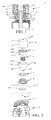
- FIG. 1 is a sectional view of an operation apparatus for a cooktop according to one embodiment of the present invention.
- the operation apparatus 1 includes a rotation shaft 2, a knob 3, a panel 4 and a light-emitting member 5.
- the rotation shaft 2 is at least partially located on an inner side of the panel 4.
- the operation apparatus 1 has at least two gears, and rotation of the rotation shaft 2 can regulate the gear of the operation apparatus 1.
- the knob 3 is connected onto the rotation shaft 2 and at least partially located on an outer side of the panel 4, and the light-emitting member 5 is located on the inner side of the panel 4.
- the cooktop in this embodiment is a gas cooktop
- the panel 4 is a cooktop panel
- the rotation shaft 2 is a valve rod of a gas valve 6.
- FIG. 2 is an exploded view of an operation apparatus for a cooktop according to one embodiment of the present invention.
- the knob 3 includes a housing 30, the housing 30 includes a cover plate 31 and a side wall 32 surrounding the cover plate 31, and the cover plate 31 is provided thereon with a light-transmissive portion 300.
- a rotation shaft accommodating portion 33 extends from the cover plate 31 towards the interior of the housing 30, the rotation shaft 2 is partially accommodated in the rotation shaft accommodating portion 33, and thus rotation of the housing 30 will drive the rotation shaft 2 to rotate.
- the knob 3 further includes a light-transmissive element disposed inside the housing 30, and the light-transmissive element includes a first light-transmissive body 41 extending from the interior of the housing 30 to and fixed to the inner side of the panel 4 and a second light-transmissive body 42 receiving light emitted by the first light-transmissive body 41.
- the first light-transmissive body 41 and the second light-transmissive body 42 are substantially tubular.
- the first light-transmissive body 41 includes a first tube portion 411 and a second tube portion 412, and a radial inner diameter of the first tube portion 411 is greater than that of the second tube portion 412.
- the second light-transmissive body 42 includes a top wall 421 and a neck portion 422 connected below the top wall 421, and a radial outer diameter of the neck portion 422 is less than the radial inner diameter of the first tube portion 411.
- the rotation shaft accommodating portion 33 is externally provided with an elastic member 43, one end of the elastic member 43 abuts against an inner wall of the first tube portion 411, and the other end abuts against the top wall 421 to make the top wall 421 elastically contact the cover plate 31.
- the housing 30 in this embodiment can rotate only after moving towards the panel 4 along an axial direction of the rotation shaft 2, to prevent children's wrong operations.
- the neck portion 422 is at least partially accommodated in the first tube portion 411.
- the internal structure of the housing 30 is extremely compact, and makes full use of the internal space of the housing.
- FIG. 3 is a three-dimensional view of a second light-transmissive body according to one embodiment of the present invention
- FIG. 4 is a three-dimensional view of a first light-transmissive body according to one embodiment of the present invention.
- the neck portion 422 of the second light-transmissive body 42 includes a rib 4220, an inner wall of the first tube portion 411 of the first light-transmissive body 41 is provided thereon with a recess 4110, and when the housing 30 moves towards the panel 4 along the axial direction of the rotation shaft 2, the rib 4220 at least partially enters the recess 4110; in this way, when the housing 30 rotates, the second light-transmissive body 42 keeps stationary in a rotating direction of the housing 30.
- the top wall 421 of the second light-transmissive body 42 is provided thereon with light-transmissive gear marks 100, and the gear marks 100 are numbers “0", “1", “2”, ..., and “9".
- the numbers are light-transmissive, while the other parts are opaque, for example, a black material may be coated thereon.
- “0” indicates a closed state
- “1” indicates Gear 1
- “2” indicates Gear 2
- “9” indicates Gear 9.
- the housing 30 drives the rotation shaft 2 to rotate to one gear of the operation apparatus 1
- the gear mark displays the current gear of the cooktop.
- the top wall 421 is a concave surface.
- FIG. 5 is a schematic view of a light-emitting member according to one embodiment of the present invention.
- the light-emitting member 5 in this embodiment is fixed to the gas valve 6 through a bracket 5, and specifically clamped to the gas valve 6 through a plurality of hooks 51.
- the second tube portion 412 of the first light-transmissive body 41 includes two projections 4120, the light-emitting member 5 is provided thereon with two cylinders 52 corresponding to one projection 4120, and the two cylinders 52 form a gap 520. After assembly of the operation apparatus, the projection 4120 is clamped to the gap 520 formed by the two cylinders 52, so that the first light-transmissive body 41 cannot be rotated.
- the housing 30 moves towards the panel 4 along the axial direction of the rotation shaft 2, the rib 4220 at least partially enters the recess 4110, and the second light-transmissive body 42 cannot be rotated either.
- the housing 30 can rotate relative to the first light-transmissive body 41 and the second light-transmissive body 42.
- an open end of the housing 30 is provided with a knob base 34 that prevents light from leaking, and the knob base 34 is an opaque annular member, which, for example, may be disposed at the open end of the housing 30 through interference fit or adhesion.
- FIG. 6 is a three-dimensional view of a housing according to another embodiment of the present invention.
- the open end of the housing 30 is provided with at least one clip 35, used for fixing the first light-transmissive body 41.
- the panel 4 has an opening 410 that allows the rotation shaft 2 to pass through, in order to prevent water or soup from leaking to the interior of the cooktop from the opening 410 or the like, a seal 45 is clamped to an edge of the opening 410, and in order to prevent the light from leaking from the opening 410, the seal 45 is made of an opaque material, for example, a black rubber material.
- the light-emitting member is located inside the housing 30, the knob 3 further includes a photovoltaic device at least providing electrical energy for the light-emitting member, and the side wall 32 is a component of the photovoltaic device and made of a material at least translucent.
- the present invention further provides a cooktop, including the operation apparatus 1 for a cooktop as described above.
- the cooktop is a gas cooktop.
Landscapes
- Engineering & Computer Science (AREA)
- Chemical & Material Sciences (AREA)
- Combustion & Propulsion (AREA)
- Mechanical Engineering (AREA)
- General Engineering & Computer Science (AREA)
- Physics & Mathematics (AREA)
- General Physics & Mathematics (AREA)
- Automation & Control Theory (AREA)
- Rotary Switch, Piano Key Switch, And Lever Switch (AREA)
- Mechanical Control Devices (AREA)
Abstract
Description
- The present invention relates to an operation apparatus for a cooktop, and in particular, to an operation apparatus for a cooktop having gear marks, and a cooktop having the operation apparatus.
- For knobs capable of emitting light on existing cooktops, light generally only plays a role of decoration, or an open/closed state of a cooktop is displayed by simply using ON/OFF of light. Information transmitted by such light-emitting knobs to users is limited, and a current fire/power state of a cooktop cannot be displayed through light. Moreover, some knobs may emit light in different colors, so as to display different fire/power of the cooktop. However, a gas cooktop produces open fire at work, the burning flame interferes with a user's judgment on the color of a knob to some extent, and thus the user cannot accurately identify the current fire/power. For cooktops designed with more gears, it is improper to use colors to display fire/power.
- Unless supported by sufficient evidences, the prior art described herein does not mean that it is known to those of ordinary skill in the art before the filing date of this application.
- An objective of the present invention is to solve the above at least one technical problem, and therefore, an operation apparatus for a cooktop that displays a relative size of a current fire/power of a cooktop more directly and accurately, and a cooktop having the operation apparatus are provided.
- To achieve the above technical objective, the present invention proposes a technical solution as follows: an operation apparatus for a cooktop, having at least two gears, the operation apparatus including a rotation shaft and a knob, where the knob includes a housing, the housing is used for driving the rotation shaft to rotate, and the housing has a light-transmissive portion; the knob further includes a built-in element disposed in the housing, and the housing rotates relative to the built-in element when rotating; a surface of the built-in element facing the light-transmissive portion has at least two gear marks; and when the housing drives the rotation shaft to rotate to one gear of the operation apparatus, one of the gear marks is visible for a user through the light-transmissive portion. The one gear mark seen by the user correspondingly displays the current gear of the operation apparatus, so that the user can directly and accurately obtain power/fire size information of the cooktop. The present invention, through a simple structure, uses a housing to rotate relative to a built-in element to achieve display of a real-time gear of the cooktop, integrates all elements that achieve gear display to the knob, and is conductive to improving flexibility of design of the knob and safety of the cooktop. The operation apparatus of the present invention may not be provided with a light source, and the manufacturing cost is low. The gear marks may be numbers such as 0-9, symbols or patterns such as different sizes of gas flames. The gear marks may be formed through printing, coating, laminating or etching. The built-in element may be an individual element, or a component including a plurality of elements. The light-transmissive portion may be a through hole directly on the housing; or the light-transmissive portion may be formed by embedding a material at least translucent onto the housing.
- In one possible implementation manner of the present invention, the gear marks are formed with a light reflective material. Thus, the gear marks can reflect surrounding light, for example, light projected down by lights of a cooker hood, so that the gear marks seem to be more eye-catching and outstanding, thereby achieving a similar effect of emitting light by a light source.
- In order to facilitate the user to view the gear marks, in one possible implementation manner of the present invention, the housing includes a cover plate and a side wall surrounding the cover plate, and the light-transmissive portion is disposed on the cover plate.
- In one possible implementation manner of the present invention, the operation apparatus for a cooktop further includes a light-emitting member, the built-in element is a light-transmissive element partially facing the light-emitting member, and the gear marks are light-transmissive gear marks.
- In one possible implementation manner of the present invention, the light-emitting member is located outside the housing, and the light-transmissive element partially extends out of the housing and is near the light-emitting member. In this way, light emitted by the light-emitting member reaches the light-transmissive gear marks via the light-transmissive element, and when the housing of the knob rotates to one gear of the operation apparatus, light of the corresponding gear mark is transmitted from the light-transmissive portion to be seen by the user.
- In one possible implementation manner of the present invention, the operation apparatus for a cooktop further includes a panel, the rotation shaft is at least partially located on an inner side of the panel, the knob is connected onto the rotation shaft and at least partially located on an outer side of the panel, and the light-emitting member is located on the inner side of the panel. The panel included in the operation apparatus may be understood as a panel for closing some parts of the operation apparatus inside the cooktop, so as to protect the parts from contamination by dirt and soup. In one embodiment, the panel may be a cooktop panel. It should be noted that, "located on an outer side of the panel" in the present invention can be understood as being located on one side of the panel facing the outside, which is a side that often can be seen by the user in a use state of the cooktop. "Located on an inner side of the panel" can be understood as being located on one side of the panel facing the interior of the cooktop, which is a side that often cannot be seen by the user in the use state of the cooktop.
- In order to make the light evenly and sufficiently guided to the interior of the housing, in one possible implementation manner of the present invention, the light-transmissive element includes a first light-transmissive body extending from the interior of the housing to and fixed to the inner side of the panel and a second light-transmissive body receiving light emitted by the first light-transmissive body, the first light-transmissive body and the second light-transmissive body are substantially tubular, and the second light-transmissive body can be partially accommodated in the first light-transmissive body.
- In order to enable the operation apparatus of the present invention to implement a certain safe function such as a children lock function, the knob may be designed to be pressed down towards the panel along an axial direction of the rotation shaft and then the housing can rotate, to prevent children from danger caused by wrong operations due to curiosity; in one possible implementation manner of the present invention, the knob further includes an elastic member, the first light-transmissive body includes a first tube portion and a second tube portion, and a radial inner diameter of the first tube portion is greater than that of the second tube portion; the second light-transmissive body includes a top wall and a neck portion connected below the top wall, the top wall is provided thereon with the gear marks, and a radial outer diameter of the neck portion is less than the radial inner diameter of the first tube portion; one end of the elastic member abuts against an inner wall of the first tube portion, and the other end abuts against the top wall to make the top wall elastically contact the cover plate; and when the housing moves towards the panel along an axial direction of the rotation shaft, the neck portion is at least partially accommodated in the first tube portion. The top wall provided with the gear marks are always in elastic contact with the cover plate, so that the gear marks are always transmitted through the light-transmissive portion clearly, which will not result in that the user cannot see clearly because movement of the housing along the axial direction of the rotation shaft causes a change in a distance between the gear marks and the light-transmissive portion. In order to prevent the light-transmissive gear marks of the top wall or opaque regions from being worn out, the top wall can be made into a concave surface.
- In one possible implementation manner of the present invention, one of the first light-transmissive body and the second light-transmissive body includes at least one rib, and the other one of the first light-transmissive body and the second light-transmissive body includes at least one recess; and when the housing moves towards the panel along an axial direction of the rotation shaft, the rib at least partially enters the recess. Thus, when the housing rotates, the second light-transmissive body keeps stationary in a rotating direction of the housing, and the light-transmissive portion transmits different gear marks when the housing rotates at different angles.
- In one possible implementation manner of the present invention, the light-emitting member is located inside the housing.
- In one possible implementation manner of the present invention, the knob further includes a photovoltaic device at least providing electrical energy for the light-emitting member, and the side wall is a component of the photovoltaic device. In this way, it is unnecessary to dispose a power supply device outside the knob, and the structure of the knob may be more flexible. In addition, a power supply device is integrated into the knob, which improves safety of the whole cooktop and prevents leaked gas from encountering sparks produced by the power supply device located inside the cooktop. The photovoltaic device can convert visible light in an environment and/or infrared radiation produced during operation of a gas cooktop to electrical energy, and the photovoltaic device can further provide electrical energy for sparking of the gas cooktop.
- In one possible implementation manner of the present invention, the side wall is made of a material at least translucent. External light can be well transmitted through the side wall and converted to electrical energy.
- In one possible implementation manner of the present invention, an open end of the housing is provided with a knob base that prevents light from leaking, which prevents light inside the knob from leaking onto the panel from the open end of the housing to cause unnecessary light and affect the appearance of the whole cooktop, and on the other hand, can improve use efficiency of the light and enhances brightness of the gear marks under the same light-emitting member.
- Based on the main objective of the present invention, the present invention further provides a cooktop, including the operation apparatus for a cooktop as described above. The gears of the cooktop of the present invention can be more intuitively displayed on the knob, and users can accurately judge relative sizes of fire/power accordingly. In use, light-emitting gear marks are displayed on the knob, which also adds a sense of fashion to the appearance of the cooktop.
- In one possible implementation manner of the present invention, the cooktop is a gas cooktop or an induction cooktop.
- The disclosure will become more fully understood from the detailed description given herein below for illustration only, and thus are not limitative of the disclosure, and wherein:
- FIG. 1
- is a sectional view of an operation apparatus for a cooktop according to one embodiment of the present invention;
- FIG. 2
- is an exploded view of an operation apparatus for a cooktop according to one embodiment of the present invention;
- FIG. 3
- is a three-dimensional view of a second light-transmissive body according to one embodiment of the present invention;
- FIG. 4
- is a three-dimensional view of a first light-transmissive body according to one embodiment of the present invention;
- FIG. 5
- is a schematic view of a light-emitting member according to one embodiment of the present invention; and
- FIG. 6
- is a three-dimensional view of a housing according to another embodiment of the present invention.
- In order to further understand the objective, structure, features and functions of the present invention, the present invention is described in detail as follows in combination with embodiments.
- Referring to
FIG. 1, FIG. 1 is a sectional view of an operation apparatus for a cooktop according to one embodiment of the present invention. The operation apparatus 1 includes arotation shaft 2, aknob 3, apanel 4 and a light-emittingmember 5. Therotation shaft 2 is at least partially located on an inner side of thepanel 4. The operation apparatus 1 has at least two gears, and rotation of therotation shaft 2 can regulate the gear of the operation apparatus 1. Theknob 3 is connected onto therotation shaft 2 and at least partially located on an outer side of thepanel 4, and the light-emittingmember 5 is located on the inner side of thepanel 4. The cooktop in this embodiment is a gas cooktop, thepanel 4 is a cooktop panel, and therotation shaft 2 is a valve rod of a gas valve 6. - Referring to
FIG. 2 in combination withFIG. 1, FIG. 2 is an exploded view of an operation apparatus for a cooktop according to one embodiment of the present invention. Theknob 3 includes ahousing 30, thehousing 30 includes acover plate 31 and aside wall 32 surrounding thecover plate 31, and thecover plate 31 is provided thereon with a light-transmissive portion 300. A rotationshaft accommodating portion 33 extends from thecover plate 31 towards the interior of thehousing 30, therotation shaft 2 is partially accommodated in the rotationshaft accommodating portion 33, and thus rotation of thehousing 30 will drive therotation shaft 2 to rotate. - The
knob 3 further includes a light-transmissive element disposed inside thehousing 30, and the light-transmissive element includes a first light-transmissive body 41 extending from the interior of thehousing 30 to and fixed to the inner side of thepanel 4 and a second light-transmissive body 42 receiving light emitted by the first light-transmissive body 41. The first light-transmissive body 41 and the second light-transmissive body 42 are substantially tubular. The first light-transmissive body 41 includes afirst tube portion 411 and asecond tube portion 412, and a radial inner diameter of thefirst tube portion 411 is greater than that of thesecond tube portion 412. The second light-transmissive body 42 includes atop wall 421 and aneck portion 422 connected below thetop wall 421, and a radial outer diameter of theneck portion 422 is less than the radial inner diameter of thefirst tube portion 411. The rotationshaft accommodating portion 33 is externally provided with anelastic member 43, one end of theelastic member 43 abuts against an inner wall of thefirst tube portion 411, and the other end abuts against thetop wall 421 to make thetop wall 421 elastically contact thecover plate 31. Thehousing 30 in this embodiment can rotate only after moving towards thepanel 4 along an axial direction of therotation shaft 2, to prevent children's wrong operations. When thehousing 30 moves towards thepanel 4 along an axial direction of therotation shaft 2, theneck portion 422 is at least partially accommodated in thefirst tube portion 411. Thus, the internal structure of thehousing 30 is extremely compact, and makes full use of the internal space of the housing. - Referring to
FIG. 3 and FIG. 4, FIG. 3 is a three-dimensional view of a second light-transmissive body according to one embodiment of the present invention, andFIG. 4 is a three-dimensional view of a first light-transmissive body according to one embodiment of the present invention. Theneck portion 422 of the second light-transmissive body 42 includes arib 4220, an inner wall of thefirst tube portion 411 of the first light-transmissive body 41 is provided thereon with arecess 4110, and when thehousing 30 moves towards thepanel 4 along the axial direction of therotation shaft 2, therib 4220 at least partially enters therecess 4110; in this way, when thehousing 30 rotates, the second light-transmissive body 42 keeps stationary in a rotating direction of thehousing 30. - As shown in
FIG. 3 , thetop wall 421 of the second light-transmissive body 42 is provided thereon with light-transmissive gear marks 100, and the gear marks 100 are numbers "0", "1", "2", ..., and "9". The numbers are light-transmissive, while the other parts are opaque, for example, a black material may be coated thereon. "0" indicates a closed state, "1" indicates Gear 1, "2" indicatesGear 2, ..., and "9" indicates Gear 9. When thehousing 30 drives therotation shaft 2 to rotate to one gear of the operation apparatus 1, the user can only see one gear mark through the light-transmissive portion 300, and the gear mark displays the current gear of the cooktop. In order to prevent the gear marks 100 on thetop wall 421 from being worn out, in another embodiment of the present invention, thetop wall 421 is a concave surface. - Referring to
FIG. 5, FIG. 5 is a schematic view of a light-emitting member according to one embodiment of the present invention. The light-emittingmember 5 in this embodiment is fixed to the gas valve 6 through abracket 5, and specifically clamped to the gas valve 6 through a plurality ofhooks 51. Thesecond tube portion 412 of the first light-transmissive body 41 includes twoprojections 4120, the light-emittingmember 5 is provided thereon with twocylinders 52 corresponding to oneprojection 4120, and the twocylinders 52 form agap 520. After assembly of the operation apparatus, theprojection 4120 is clamped to thegap 520 formed by the twocylinders 52, so that the first light-transmissive body 41 cannot be rotated. When thehousing 30 moves towards thepanel 4 along the axial direction of therotation shaft 2, therib 4220 at least partially enters therecess 4110, and the second light-transmissive body 42 cannot be rotated either. Thus, thehousing 30 can rotate relative to the first light-transmissive body 41 and the second light-transmissive body 42. - In order to prevent light leakage and to better fix the first light-
transmissive body 41, an open end of thehousing 30 is provided with aknob base 34 that prevents light from leaking, and theknob base 34 is an opaque annular member, which, for example, may be disposed at the open end of thehousing 30 through interference fit or adhesion. As shown inFIG. 6, FIG. 6 is a three-dimensional view of a housing according to another embodiment of the present invention. In another embodiment of the present invention, the open end of thehousing 30 is provided with at least oneclip 35, used for fixing the first light-transmissive body 41. As shown inFIG. 2 , thepanel 4 has anopening 410 that allows therotation shaft 2 to pass through, in order to prevent water or soup from leaking to the interior of the cooktop from theopening 410 or the like, aseal 45 is clamped to an edge of theopening 410, and in order to prevent the light from leaking from theopening 410, theseal 45 is made of an opaque material, for example, a black rubber material. - In another embodiment of the present invention, the light-emitting member is located inside the
housing 30, theknob 3 further includes a photovoltaic device at least providing electrical energy for the light-emitting member, and theside wall 32 is a component of the photovoltaic device and made of a material at least translucent. - The present invention further provides a cooktop, including the operation apparatus 1 for a cooktop as described above. In one embodiment, the cooktop is a gas cooktop.
- The present invention has been described through the above related embodiments, but the embodiments are merely examples of implementing the present invention. It should be pointed out that, the embodiments disclosed do not limit the scope of the present invention. On the contrary, variations and modifications made without departing from the spirit and scope of the present invention all fall within the patent protection scope of the present invention.
-
- 1
- operation apparatus;
- 2
- rotation shaft;
- 3
- knob;
- 4
- panel;
- 5
- light-emitting member;
- 6
- gas valve;
- 30
- knob;
- 31
- cover plate;
- 32
- side wall;
- 33
- rotation shaft accommodating portion;
- 34
- knob base;
- 35
- clip;
- 41
- first light-transmissive body;
- 42
- second light-transmissive body;
- 43
- elastic member;
- 45
- seal;
- 50
- bracket;
- 51
- hook;
- 52
- cylinder;
- 100
- gear mark;
- 300
- light-transmissive portion;
- 410
- opening;
- 411
- first tube portion;
- 412
- second tube portion;
- 421
- top wall;
- 422
- neck portion;
- 520
- gap;
- 4110
- recess;
- 4120
- projection;
- 4220
- rib
Claims (15)
- An operation apparatus (1) for a cooktop, having at least two gears, the operation apparatus (1) comprising:a rotation shaft (2), anda knob (3), wherein the knob (3) comprises a housing (30), the housing (30) is used for driving the rotation shaft (2) to rotate, and the housing (30) has a light-transmissive portion (300),characterized in that,the knob (3) further comprises a built-in element disposed in the housing (30), and the housing (30) rotates relative to the built-in element when rotating;a surface of the built-in element facing the light-transmissive portion (300) has at least two gear marks (100); andwhen the housing (30) drives the rotation shaft (2) to rotate to one gear of the operation apparatus (1), one of the gear marks (100) is visible for a user through the light-transmissive portion (300).
- The operation apparatus (1) for a cooktop according to claim 1, characterized in that, the gear marks (100) are formed with a light reflective material.
- The operation apparatus (1) for a cooktop according to claim 1, characterized in that, the housing (30) comprises a cover plate (31) and a side wall (32) surrounding the cover plate (31), and the light-transmissive portion (300) is disposed on the cover plate (31).
- The operation apparatus (1) for a cooktop according to claim 3, characterized in that, the operation apparatus (1) further comprises a light-emitting member (5),
the built-in element is a light-transmissive element partially facing the light-emitting member (5), and
the gear marks (100) are light-transmissive gear marks (100). - The operation apparatus (1) for a cooktop according to claim 4, characterized in that, the light-emitting member (5) is located outside the housing (30), and the light-transmissive element partially extends out of the housing (30) and is near the light-emitting member (5).
- The operation apparatus (1) for a cooktop according to claim 5, characterized by further comprising a panel (4),
wherein the rotation shaft (2) is at least partially located on an inner side of the panel (4),
the knob (3) is connected onto the rotation shaft (2) and at least partially located on an outer side of the panel (4), and
the light-emitting member (5) is located on the inner side of the panel (4). - The operation apparatus (1) for a cooktop according to claim 6, characterized in that, the light-transmissive element comprises a first light-transmissive body (41) extending from the interior of the housing (30) to and fixed to the inner side of the panel (4) and a second light-transmissive body (42) receiving light emitted by the first light-transmissive body (41), the first light-transmissive body (41) and the second light-transmissive body (42) are substantially tubular, and the second light-transmissive body (42) can be partially accommodated in the first light-transmissive body (41).
- The operation apparatus (1) for a cooktop according to claim 7, characterized in that, the knob (3) further comprises an elastic member (43),
the first light-transmissive body (41) comprises a first tube portion (411) and a second tube portion (412), and a radial inner diameter of the first tube portion (411) is greater than that of the second tube portion (412);
the second light-transmissive body (42) comprises a top wall (421) and a neck portion (422) connected below the top wall (421), the top wall (421) is provided thereon with the gear marks (100), and a radial outer diameter of the neck portion (422) is less than the radial inner diameter of the first tube portion (411);
one end of the elastic member (43) abuts against an inner wall of the first tube portion (411), and the other end abuts against the top wall (421) to make the top wall (421) elastically contact the cover plate (31); and
when the housing (30) moves towards the panel (4) along an axial direction of the rotation shaft (2), the neck portion (422) is at least partially accommodated in the first tube portion (411). - The operation apparatus (1) for a cooktop according to claim 7, characterized in that, one of the first light-transmissive body (41) and the second light-transmissive body (42) comprises at least one rib (4220), and the other one of the first light-transmissive body (41) and the second light-transmissive body (42) comprises at least one recess (4110); and when the housing (30) moves towards the panel (4) along an axial direction of the rotation shaft (2), the rib (4220) at least partially enters the recess (4110).
- The operation apparatus (1) for a cooktop according to claim 4, characterized in that, the light-emitting member (5) is located inside the housing (30).
- The operation apparatus (1) for a cooktop according to claim 10, characterized in that, the knob (3) further comprises a photovoltaic device at least providing electrical energy for the light-emitting member (5), and the side wall (32) is a component of the photovoltaic device.
- The operation apparatus (1) for a cooktop according to claim 11, characterized in that, the side wall (32) is made of a material at least translucent.
- The operation apparatus (1) for a cooktop according to any one of claims 1 to 12, characterized in that, an open end of the housing (30) is provided with a knob base (34) that prevents light from leaking.
- A cooktop, characterized by comprising the operation apparatus (1) for a cooktop according to any one of claims 1 to 13.
- The cooktop according to claim 14, characterized in that, the cooktop is a gas cooktop or an induction cooktop.
Applications Claiming Priority (1)
| Application Number | Priority Date | Filing Date | Title |
|---|---|---|---|
| CN201410370038.8A CN105333460B (en) | 2014-07-30 | 2014-07-30 | Operating device of stove and stove |
Publications (1)
| Publication Number | Publication Date |
|---|---|
| EP2980487A1 true EP2980487A1 (en) | 2016-02-03 |
Family
ID=53800833
Family Applications (1)
| Application Number | Title | Priority Date | Filing Date |
|---|---|---|---|
| EP15178195.2A Withdrawn EP2980487A1 (en) | 2014-07-30 | 2015-07-24 | Operation apparatus for cooktop, and cooktop |
Country Status (2)
| Country | Link |
|---|---|
| EP (1) | EP2980487A1 (en) |
| CN (1) | CN105333460B (en) |
Cited By (3)
| Publication number | Priority date | Publication date | Assignee | Title |
|---|---|---|---|---|
| JP2016134350A (en) * | 2015-01-21 | 2016-07-25 | アルプス電気株式会社 | Switch device |
| ES2702791A1 (en) * | 2017-09-05 | 2019-03-05 | Bsh Electrodomesticos Espana Sa | CONTROL DEVICE FOR A DOMESTIC APPLIANCES AND DOMESTIC APPLIANCE (Machine-translation by Google Translate, not legally binding) |
| EP4036475A1 (en) * | 2021-02-01 | 2022-08-03 | Renta Elektrikli Ev Aletleri Sanayi Ve Dis Ticaret Limited Sirketi | Domestic gas stove knob structure |
Families Citing this family (6)
| Publication number | Priority date | Publication date | Assignee | Title |
|---|---|---|---|---|
| CN108019800B (en) * | 2016-10-28 | 2020-01-24 | 青岛海尔洗碗机有限公司 | Gas stove and light-emitting device thereof |
| CN106968085B (en) * | 2017-04-28 | 2021-09-14 | 青岛海尔洗涤电器有限公司 | Washing machine knob assembly, assembling method and washing machine |
| CN108224493B (en) * | 2018-01-11 | 2024-01-09 | 青岛海尔智慧厨房电器有限公司 | Firepower indicating device and gas stove |
| CN111076230B (en) * | 2019-12-31 | 2025-08-12 | 华帝股份有限公司 | Gas stove knob capable of displaying fire gear and gas stove using same |
| CN111237818A (en) * | 2020-02-28 | 2020-06-05 | 华帝股份有限公司 | Gas stove knob capable of displaying firepower gear and gas stove using same |
| CN111237819A (en) * | 2020-02-28 | 2020-06-05 | 华帝股份有限公司 | Gas stove knob capable of displaying firepower gear and gas stove using same |
Citations (5)
| Publication number | Priority date | Publication date | Assignee | Title |
|---|---|---|---|---|
| FR2370321A1 (en) * | 1976-11-04 | 1978-06-02 | Odenwalder Kunststoffwerke | Rotary knob with position indication - has numbers on end face visible through aperture in separately supported disc cover |
| US6178916B1 (en) * | 1998-01-20 | 2001-01-30 | Delco Electronics Corporation | Compact, low-cost, rotary knob with indicator |
| US20060219156A1 (en) * | 2005-03-30 | 2006-10-05 | Douglas Denton | Control |
| US20120012721A1 (en) * | 2010-07-15 | 2012-01-19 | E.G.O. Elektro-Geratebau Gmbh | Holding Device for an Operating Device |
| EP2653785A1 (en) * | 2012-04-16 | 2013-10-23 | Whirlpool Corporation | Lighted signals to provide direction to user |
Family Cites Families (10)
| Publication number | Priority date | Publication date | Assignee | Title |
|---|---|---|---|---|
| DE3435291A1 (en) * | 1984-09-26 | 1986-04-03 | Licentia Patent-Verwaltungs-Gmbh, 6000 Frankfurt | Retractable rotary knob |
| US6012445A (en) * | 1999-02-11 | 2000-01-11 | Santelli, Jr.; Albert | Appliance control knob guard |
| JP4120390B2 (en) * | 2002-12-20 | 2008-07-16 | 松下電器産業株式会社 | Cooker |
| DE102005024934B4 (en) * | 2005-05-31 | 2014-03-27 | BSH Bosch und Siemens Hausgeräte GmbH | Control panel arrangement for a domestic appliance |
| CN1888226A (en) * | 2005-06-29 | 2007-01-03 | 乐金电子(天津)电器有限公司 | Rotary disc knob structure for rotary drum washing machine and producing method thereof |
| FR2932727B1 (en) * | 2008-06-20 | 2012-10-26 | Valeo Systemes Thermiques | CONTROL DEVICE FOR CONTROLLING FUNCTIONS OF A CONTROL PANEL FOR A MOTOR VEHICLE AND CONTROL PANEL THEREFOR |
| CN102305996B (en) * | 2011-04-29 | 2013-05-01 | 重庆欧恺电器有限公司 | Electrical appliance timer knob with optical-acoustic indication function |
| CN102997287B (en) * | 2011-09-19 | 2017-09-12 | 博西华电器(江苏)有限公司 | Kitchen range and its combination with smoke exhaust ventilator |
| US9146033B2 (en) * | 2013-01-23 | 2015-09-29 | General Electric Company | Illuminated knobs for an appliance |
| CN203349307U (en) * | 2013-06-20 | 2013-12-18 | 美的集团股份有限公司 | Gas stove |
-
2014
- 2014-07-30 CN CN201410370038.8A patent/CN105333460B/en active Active
-
2015
- 2015-07-24 EP EP15178195.2A patent/EP2980487A1/en not_active Withdrawn
Patent Citations (5)
| Publication number | Priority date | Publication date | Assignee | Title |
|---|---|---|---|---|
| FR2370321A1 (en) * | 1976-11-04 | 1978-06-02 | Odenwalder Kunststoffwerke | Rotary knob with position indication - has numbers on end face visible through aperture in separately supported disc cover |
| US6178916B1 (en) * | 1998-01-20 | 2001-01-30 | Delco Electronics Corporation | Compact, low-cost, rotary knob with indicator |
| US20060219156A1 (en) * | 2005-03-30 | 2006-10-05 | Douglas Denton | Control |
| US20120012721A1 (en) * | 2010-07-15 | 2012-01-19 | E.G.O. Elektro-Geratebau Gmbh | Holding Device for an Operating Device |
| EP2653785A1 (en) * | 2012-04-16 | 2013-10-23 | Whirlpool Corporation | Lighted signals to provide direction to user |
Cited By (3)
| Publication number | Priority date | Publication date | Assignee | Title |
|---|---|---|---|---|
| JP2016134350A (en) * | 2015-01-21 | 2016-07-25 | アルプス電気株式会社 | Switch device |
| ES2702791A1 (en) * | 2017-09-05 | 2019-03-05 | Bsh Electrodomesticos Espana Sa | CONTROL DEVICE FOR A DOMESTIC APPLIANCES AND DOMESTIC APPLIANCE (Machine-translation by Google Translate, not legally binding) |
| EP4036475A1 (en) * | 2021-02-01 | 2022-08-03 | Renta Elektrikli Ev Aletleri Sanayi Ve Dis Ticaret Limited Sirketi | Domestic gas stove knob structure |
Also Published As
| Publication number | Publication date |
|---|---|
| CN105333460B (en) | 2020-10-16 |
| CN105333460A (en) | 2016-02-17 |
Similar Documents
| Publication | Publication Date | Title |
|---|---|---|
| CN105333460B (en) | Operating device of stove and stove | |
| EP2659499B1 (en) | Illuminated knob for household appliance | |
| US7878672B2 (en) | Door knob having illuminative lighting | |
| EP2980486A1 (en) | Operation apparatus for cooktop, and cooktop | |
| CN108019800B (en) | Gas stove and light-emitting device thereof | |
| CN207196551U (en) | Full view illuminated knobs for gas stoves | |
| CN104134561A (en) | Metal key module, control box module with metal key module, and range hood | |
| CN106545896A (en) | A kitchen electric knob with warning function and its working method | |
| WO2013122555A2 (en) | Contactless controllable illuminated control mechanism | |
| JP2016118965A (en) | Indicating-lamp built-in transmitter, transmitter, and indicating lamp | |
| CN104235885B (en) | Gas stove | |
| CN201396823Y (en) | Light spot indication gas stove fire switch device | |
| TWM554547U (en) | Gas stove knob luminescent with full beam angle | |
| CN115657785A (en) | Knob subassembly, control box subassembly and consumer | |
| CN224261664U (en) | LED lighting fixtures | |
| CN204809093U (en) | Rotary switch for range hood | |
| JP4569501B2 (en) | Cooker | |
| CN206410188U (en) | A kitchen electric knob with a color-changing warning function | |
| CN215723100U (en) | Light-adjusting knob | |
| CN214380856U (en) | Operation display structure and kitchen appliance | |
| CN203795198U (en) | Sterilizing and drying all-in-one machine improving user experience | |
| CN219346557U (en) | Bright knob and gas stove comprising same | |
| CN211902447U (en) | Knob lamp for integrated stove | |
| EP3771944B1 (en) | Heating appliance | |
| JP2010257774A (en) | Rotary operation device |
Legal Events
| Date | Code | Title | Description |
|---|---|---|---|
| PUAI | Public reference made under article 153(3) epc to a published international application that has entered the european phase |
Free format text: ORIGINAL CODE: 0009012 |
|
| AK | Designated contracting states |
Kind code of ref document: A1 Designated state(s): AL AT BE BG CH CY CZ DE DK EE ES FI FR GB GR HR HU IE IS IT LI LT LU LV MC MK MT NL NO PL PT RO RS SE SI SK SM TR |
|
| AX | Request for extension of the european patent |
Extension state: BA ME |
|
| 17P | Request for examination filed |
Effective date: 20160803 |
|
| RBV | Designated contracting states (corrected) |
Designated state(s): AL AT BE BG CH CY CZ DE DK EE ES FI FR GB GR HR HU IE IS IT LI LT LU LV MC MK MT NL NO PL PT RO RS SE SI SK SM TR |
|
| GRAP | Despatch of communication of intention to grant a patent |
Free format text: ORIGINAL CODE: EPIDOSNIGR1 |
|
| RIC1 | Information provided on ipc code assigned before grant |
Ipc: F24C 3/12 20060101AFI20180619BHEP Ipc: G05G 1/10 20060101ALI20180619BHEP |
|
| INTG | Intention to grant announced |
Effective date: 20180705 |
|
| RIC1 | Information provided on ipc code assigned before grant |
Ipc: G05G 1/10 20060101ALI20180625BHEP Ipc: H05B 6/12 20060101ALI20180625BHEP Ipc: F24C 3/12 20060101ALI20180625BHEP Ipc: F24C 7/08 20060101AFI20180625BHEP |
|
| STAA | Information on the status of an ep patent application or granted ep patent |
Free format text: STATUS: THE APPLICATION IS DEEMED TO BE WITHDRAWN |
|
| 18D | Application deemed to be withdrawn |
Effective date: 20181116 |