EP2980442A1 - Damping valve - Google Patents
Damping valve Download PDFInfo
- Publication number
- EP2980442A1 EP2980442A1 EP14775956.7A EP14775956A EP2980442A1 EP 2980442 A1 EP2980442 A1 EP 2980442A1 EP 14775956 A EP14775956 A EP 14775956A EP 2980442 A1 EP2980442 A1 EP 2980442A1
- Authority
- EP
- European Patent Office
- Prior art keywords
- valve
- spacer
- piston
- peripheral sheet
- annular
- Prior art date
- Legal status (The legal status is an assumption and is not a legal conclusion. Google has not performed a legal analysis and makes no representation as to the accuracy of the status listed.)
- Granted
Links
Images




Classifications
-
- F—MECHANICAL ENGINEERING; LIGHTING; HEATING; WEAPONS; BLASTING
- F16—ENGINEERING ELEMENTS AND UNITS; GENERAL MEASURES FOR PRODUCING AND MAINTAINING EFFECTIVE FUNCTIONING OF MACHINES OR INSTALLATIONS; THERMAL INSULATION IN GENERAL
- F16F—SPRINGS; SHOCK-ABSORBERS; MEANS FOR DAMPING VIBRATION
- F16F9/00—Springs, vibration-dampers, shock-absorbers, or similarly-constructed movement-dampers using a fluid or the equivalent as damping medium
- F16F9/32—Details
- F16F9/34—Special valve constructions; Shape or construction of throttling passages
- F16F9/348—Throttling passages in the form of annular discs or other plate-like elements which may or may not have a spring action, operating in opposite directions or singly, e.g. annular discs positioned on top of the valve or piston body
-
- F—MECHANICAL ENGINEERING; LIGHTING; HEATING; WEAPONS; BLASTING
- F16—ENGINEERING ELEMENTS AND UNITS; GENERAL MEASURES FOR PRODUCING AND MAINTAINING EFFECTIVE FUNCTIONING OF MACHINES OR INSTALLATIONS; THERMAL INSULATION IN GENERAL
- F16F—SPRINGS; SHOCK-ABSORBERS; MEANS FOR DAMPING VIBRATION
- F16F9/00—Springs, vibration-dampers, shock-absorbers, or similarly-constructed movement-dampers using a fluid or the equivalent as damping medium
- F16F9/32—Details
- F16F9/34—Special valve constructions; Shape or construction of throttling passages
- F16F9/348—Throttling passages in the form of annular discs or other plate-like elements which may or may not have a spring action, operating in opposite directions or singly, e.g. annular discs positioned on top of the valve or piston body
- F16F9/3484—Throttling passages in the form of annular discs or other plate-like elements which may or may not have a spring action, operating in opposite directions or singly, e.g. annular discs positioned on top of the valve or piston body characterised by features of the annular discs per se, singularly or in combination
-
- F—MECHANICAL ENGINEERING; LIGHTING; HEATING; WEAPONS; BLASTING
- F16—ENGINEERING ELEMENTS AND UNITS; GENERAL MEASURES FOR PRODUCING AND MAINTAINING EFFECTIVE FUNCTIONING OF MACHINES OR INSTALLATIONS; THERMAL INSULATION IN GENERAL
- F16F—SPRINGS; SHOCK-ABSORBERS; MEANS FOR DAMPING VIBRATION
- F16F9/00—Springs, vibration-dampers, shock-absorbers, or similarly-constructed movement-dampers using a fluid or the equivalent as damping medium
- F16F9/32—Details
- F16F9/34—Special valve constructions; Shape or construction of throttling passages
- F16F9/348—Throttling passages in the form of annular discs or other plate-like elements which may or may not have a spring action, operating in opposite directions or singly, e.g. annular discs positioned on top of the valve or piston body
- F16F9/3488—Throttling passages in the form of annular discs or other plate-like elements which may or may not have a spring action, operating in opposite directions or singly, e.g. annular discs positioned on top of the valve or piston body characterised by features intended to affect valve bias or pre-stress
-
- F—MECHANICAL ENGINEERING; LIGHTING; HEATING; WEAPONS; BLASTING
- F16—ENGINEERING ELEMENTS AND UNITS; GENERAL MEASURES FOR PRODUCING AND MAINTAINING EFFECTIVE FUNCTIONING OF MACHINES OR INSTALLATIONS; THERMAL INSULATION IN GENERAL
- F16K—VALVES; TAPS; COCKS; ACTUATING-FLOATS; DEVICES FOR VENTING OR AERATING
- F16K47/00—Means in valves for absorbing fluid energy
- F16K47/04—Means in valves for absorbing fluid energy for decreasing pressure or noise level, the throttle being incorporated in the closure member
Definitions
- a damping valve includes an annular valve disc, the valve disc having an annular outer peripheral sheet that projects toward an axial direction of the valve disc an inner peripheral sheet that is provided on an inside of the outer peripheral sheet and projects toward the axial direction an annular window formed between the outer peripheral sheet and the inner peripheral sheet and a port that communicates with the annular window an annular leaf valve that is laminated on the valve disc and is seated/unseated on the outer peripheral sheet an annular spacer that is interposed between the leaf valve and the inner peripheral sheet and sets an initial deflection amount of the leaf valve a positioning part that restricts positional deviation of the spacer in a radial direction relative to the valve disc.
- the piston rod 5 is inserted into the insertion hole 11 of the piston 1, and the distal end 5a of the piston rod 5 projects above the piston 1.
- the outer diameter of the distal end 5a of the piston rod 5 is set to be smaller than the outer diameter of upper side of the piston rod 5 above the distal end 5a in FIG. 1 , and a stepped part 5b is formed at the portion where the outer diameter of the upper side of the piston rod 5 and the outer diameter of the distal end 5a differ.
- the structure of a spacer 7 differs from that in the damping valve of the first embodiment.
- the members that constitute the damping valve other than the spacer 7 are the same as those constituting the damping valve of the first embodiment.
- members which are the same will be assigned the same reference numerals and detailed explanations thereof will be omitted.
- piston ports 93 of the piston 9 function as pressure-side ports.
- the pressure-side leaf valves 43 apply resistance to the flow of liquid passing through the piston ports 93 from the pressure-side chamber 42 toward the extension-side chamber 41, and thereby the damping valve exerts a pressure-side damping force.
- valve disc 8 shown in FIG. 10 three arcuate ports 85 are provided, and one projection 86 is provided on the outer periphery of each port 85.
- the inner walls on the spacer 3 side of the projections 86 are flush with the wall surfaces on the outer periphery side of the ports 85.
- the ports 85 and the projections 86 can be molded simultaneously when sinter molding the valve disc 8 without any arced surfaces being formed on the side surfaces of the projections 86.
Landscapes
- Engineering & Computer Science (AREA)
- General Engineering & Computer Science (AREA)
- Mechanical Engineering (AREA)
- Fluid-Damping Devices (AREA)
- Lift Valve (AREA)
Abstract
Description
- The present invention relates to a damping valve.
- A damping valve is used in, for example, a piston that constitutes a vehicle shock absorber. A damping valve is constituted by a piston and an annular leaf valve. A piston includes an annular outer peripheral sheet, an inner peripheral sheet provided on the inside of the outer peripheral sheet, an annular window formed between the outer peripheral sheet and the inner peripheral sheet, and a port that communicates with the annular window. The annular leaf valve is laminated on the piston, and an inner peripheral side of the leaf valve is fixed to a piston rod and an outer peripheral portion of the leaf valve is seated/unseated on the outer peripheral sheet.
- The leaf valve is laminated between the outer peripheral sheet and the inner peripheral sheet. Normally, by making the height in the axial direction of the outer peripheral sheet greater than the height in the axial direction of the inner peripheral sheet, the leaf valve can be deflected in advance just by laminating and fixing the leaf valve on the piston. Thereby, a valve opening pressure of the leaf valve is set. A spacer is interposed between the inner peripheral sheet and the leaf valve, and the outer diameter of the spacer is nearly the same as the outer diameter of the inner peripheral sheet. Thereby, an initial deflection amount imparted to the leaf valve can be adjusted, and thus the opening valve pressure of the leaf valve can be adjusted (for example, refer to
JP2000-55103A - A leaf valve is generally constituted by laminating a plurality of thin annular plates, and thus a damping valve having such a leaf valve is made of numerous parts. When assembling such a damping valve, first, the piston, spacer, and leaf valve are assembled on a rod-shaped retaining pin, and then these parts are removed from the retaining needle and mounted on the piston rod. Therefore, the damping valve can be efficiently assembled (refer to
JP2001-20990A - However, in the structure of the above-described damping valve, when moving the piston, spacer, and leaf valve from the retaining pin to the piston rod, the spacer can move freely in the radial direction between the piston and leaf valve, and thus positional deviation of the spacer may occur. In a state in which the spacer has positionally deviated by a large amount, the spacer may interfere with the piston rod when trying to assemble the spacer on the piston rod together with the piston and the leaf valve. Further, since the spacer is interposed between the leaf valve and the piston, the spacer is not visible from the outside. Therefore, there has been a problem in that the process of assembling these parts on the piston rod is troublesome.
- Thus, an object of the present invention is to provide a damping valve with improved assemblability.
- According to one embodiment, a damping valve includes an annular valve disc, the valve disc having an annular outer peripheral sheet that projects toward an axial direction of the valve disc an inner peripheral sheet that is provided on an inside of the outer peripheral sheet and projects toward the axial direction an annular window formed between the outer peripheral sheet and the inner peripheral sheet and a port that communicates with the annular window an annular leaf valve that is laminated on the valve disc and is seated/unseated on the outer peripheral sheet an annular spacer that is interposed between the leaf valve and the inner peripheral sheet and sets an initial deflection amount of the leaf valve a positioning part that restricts positional deviation of the spacer in a radial direction relative to the valve disc.
-
-
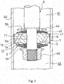
FIG. 1 is a vertical cross-section view of a piston of a shock absorber in which a damping valve according to a first embodiment of the present invention is implemented; -
FIG. 2 illustrates a state in which the damping valve is temporarily assembled on a retaining pin; -
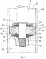
FIG. 3 is a vertical cross-section view of a piston of a shock absorber in which a damping valve according to a second embodiment of the present invention is implemented; -
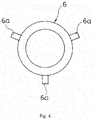
FIG. 4 is a plan view of a spacer in the damping valve according to the second embodiment: -
FIG. 5A is a plan view of a piston of a shock absorber and a spacer in which a damping valve of an alternative embodiment of the second embodiment is implemented; -
FIG. 5B is a cross-section view when the damping valve shown inFIG. 5A is cut along line VB-VB; -
FIG. 6 is a vertical cross-section view of a piston of a shock absorber in which a damping valve according to a third embodiment of the present invention is implemented; -
FIG. 7 is a plan view of a spacer of the damping valve according to the third embodiment; -
FIG. 8 is a vertical cross-section view of a piston of a shock absorber in which a damping valve according to a fourth embodiment of the present invention is implemented; -
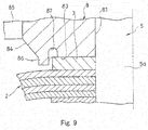
FIG. 9 is a partially expanded vertical cross-section view of a piston of a shock absorber in which a damping valve according to an alternative embodiment of the fourth embodiment is implemented; and -
FIG. 10 is a plan view of a valve disc in a damping valve according to another alternative embodiment of the fourth embodiment. - Embodiments of the present invention will now be explained below referring to the drawings.
- As shown in
FIG. 1 , a damping valve according to a first embodiment of the present invention is an extension-side damping valve that produces a damping force when the shock absorber extends. This damping valve includes apiston 1 that serves as a valve disc, aleaf valve 2, and aspacer 3. - A shock absorber to which the damping valve of the present embodiment is applied is well known, and thus it will be briefly explained below without any detailed illustration.
- The shock absorber includes, for example, a
cylinder 40, a rod guide (not illustrated) that seals a lower end of thecylinder 40, apiston rod 5 that slidably penetrates through the rod guide, and thepiston 1 that is fixed to adistal end 5a of thepiston rod 5 that forms a shaft member, thedistal end 5a being inserted into thepiston 1. The shock absorber also includes an extension-side chamber 41 (upper side inFIG. 1 ) and a pressure-side chamber 42 (lower side inFIG. 1 ) that are separated by thepiston 1 within thecylinder 40, and a sealing member (not illustrated) that seals an upper end of thecylinder 40. The shock absorber further includes a reservoir or an air chamber (not illustrated) that compensates a volume change within the cylinder in an amount of the volume of thepiston rod 5 that moves into and out of thecylinder 40. Hydraulic oil that serves as a fluid is also filled into thecylinder 40 that constitutes the shock absorber. - In the damping valve according to the present embodiment utilized in the above-described shock absorber, when the
piston 1 moves upwards inFIG. 1 relative to thecylinder 40, the pressure within the extension-side chamber 41 rises, and thus the hydraulic oil moves from the extension-side chamber 41 to the pressure-side chamber 42 via aport 15. At this time, resistance is applied to the hydraulic oil moving through theport 15 by theleaf valve 2, and thus a prescribed pressure loss occurs between the extension-side chamber 41 and the pressure-side chamber 42. Thereby, the damping valve functions as a damping force producing element that produces a prescribed damping force in the shock absorber. - The damping valve of the present embodiment will be explained in further detail below referring to
FIG. 1 . - The
piston 1, which serves as a valve disc, is formed in an annular shape. Thepiston 1 includes aninsertion hole 11 at the axial center thereof into which thedistal end 5a of thepiston rod 5 that constitutes the shock absorber is inserted, and an annular outerperipheral sheet 12 that is formed at one end (the lower end inFIG. 1 ) of thepiston 1 and projects in the axial direction. Thepiston 1 also includes an innerperipheral sheet 13 that is provided inside of the outerperipheral sheet 12 at one end of thepiston 1 similar to the outerperipheral sheet 12 and projects in the axial direction, and anannular window 14 that is similarly formed at one end of thepiston 1 between the outerperipheral sheet 12 and the innerperipheral sheet 13. Thepiston 1 further includes aport 15 that communicates with theannular window 14 from the other end side of thepiston 1. - The height in the axial direction of the outer
peripheral sheet 12 is greater than the height in the axial direction of the innerperipheral sheet 13. A pressure-side port 16 that permits the flow of hydraulic oil from the pressure-side chamber 42 toward the extension-side chamber 41 when the shock absorber contracts is provided in thepiston 1. - As described above, the
piston rod 5 is inserted into theinsertion hole 11 of thepiston 1, and thedistal end 5a of thepiston rod 5 projects above thepiston 1. The outer diameter of thedistal end 5a of thepiston rod 5 is set to be smaller than the outer diameter of upper side of thepiston rod 5 above thedistal end 5a inFIG. 1 , and astepped part 5b is formed at the portion where the outer diameter of the upper side of thepiston rod 5 and the outer diameter of thedistal end 5a differ. - The
leaf valve 2 is formed by laminating a plurality of thin annular plates. The annular plates of theleaf valve 2 are laminated on the lower end of thepiston 1, and the inner peripheral side of theleaf valve 2 is fixed to thedistal end 5a of thepiston rod 5 whereas the outer peripheral side of theleaf valve 2 is permitted to deflect. - The outer peripheral side of the
leaf valve 2 is seated on the outerperipheral sheet 12. When the differential pressure between the pressure in the extension-side chamber 41 received from theport 15 and the pressure in the pressure-side chamber 42 reaches a valve opening pressure, theleaf valve 2 deflects and becomes unseated from the outerperipheral sheet 12. Thereby, theport 15 is opened and resistance is applied to the flow of fluid passing through theport 15. In this way, the damping valve is configured such that an extension-side damping passage is formed by theleaf valve 2 and theport 15 when the shock absorber extends, and thus an extension-side damping force is exerted. - The
spacer 3 is formed in an annular shape, and thedistal end 5a of thepiston rod 5 is inserted into the inner peripheral side of thespacer 3. Thespacer 3 is sandwiched between the innerperipheral sheet 13 of thepiston 1 and theleaf valve 2, and is fixed to thepiston rod 5 similar to theleaf valve 2. - In the present embodiment, the
spacer 3 is integrated by being welded or adhered to the annular plate that is disposed at the uppermost level inFIG. 1 among the plurality of annular plates that constitute theleaf valve 2. Thereby, a positioning part is constituted in the present embodiment. - A plurality of annular pressure-
side leaf valves 43 are laminated at the upper end inFIG. 1 of thepiston 1, and these pressure-side leaf valves 43 open and close an outlet end of a pressure-side port 16. Further, anannular valve stopper 44 that restricts the amount of deflection of the pressure-side leaf valves 43 is laminated above the pressure-side leaf valves 43 inFIG. 1 . - In the present embodiment, a lower end in
FIG. 1 of the pressure-side port 16 serves as an suction-side end that suctions the fluid, and this suction-side end is disposed more toward the outer peripheral side than the outerperipheral sheet 12 provided on one end of thepiston 1 so that the suction-side end of the pressure-side port 16 cannot be blocked by theleaf valve 2 laminated on thepiston 1. - An upper end in
FIG. 1 of theport 15 serves as a suction-side end, and this suction-side end is formed more toward the outer periphery than the pressure-side port 16 formed on the other end (upper end) of thepiston 1. The suction-side end of theport 15 opens more toward the outer periphery than a pressure-side sheet 17 on which the pressure-side leaf valves 43 are seated/unseated. Therefore, the suction-side end of theport 15 is formed so that it cannot be blocked by the pressure-side leaf valves 43. - When the
piston 1 moves downward inFIG. 1 , the pressure within the pressure-side chamber 42 rises. Thereby, the fluid moves from the pressure-side chamber 42 into the extension-side chamber 41 via the pressure-side port 16, and resistance is applied to this flow of fluid by the pressure-side leaf valves 43. Thus, the damping valve exerts a pressure-side damping force when the shock absorber contracts. - The
spacer 3,leaf valve 2, pressure-side leaf valves 43, and thevalve stopper 44 that are laminated in thepiston 1 are assembled on the outer periphery of thedistal end 5a of thepiston rod 5 together with thepiston 1, and then fixed to thepiston rod 5 by fastening with apiston nut 45 that is threaded onto the tip of thedistal end 5a. - The thickness in the axial direction of the
spacer 3 is set to be thinner than the difference between the height in the axial direction of the outerperipheral sheet 12 of thepiston 1 and the height in the axial direction of the innerperipheral sheet 13. As described above, if theleaf valve 2 is laminated on thepiston 1 via thespacer 3 and then fixed to thepiston rod 5, an initial deflection is imparted to theleaf valve 2 by the height difference between the end of thespacer 3 and the end of the outerperipheral sheet 12. Thus, the outer peripheral side of theleaf valve 2 deflects and becomes seated on the outerperipheral sheet 12. The initial deflection amount can be adjusted by changing the thickness of thespacer 3, and thus it is possible to set the valve opening pressure of theleaf valve 2 to a predetermined value by the thickness of thespacer 3. - In order to assemble the
piston 1, thespacer 3, theleaf valve 2, the pressure-side leaf valves 43, and thevalve stopper 44 on thedistal end 5a of thepiston rod 5, these members are first temporarily assembled on a retaining pin W as shown inFIG. 2 before assembling them on thepiston rod 5. At this time, thespacer 3 is interposed between theleaf valve 2 and thepiston 1, and thus it is difficult to see thespacer 3 from the outside once it has been temporarily assembled on the retaining pin W. - When moving the above members from the retaining pin W to the
distal end 5a of thepiston rod 5, theleaf valve 2 is grasped together with thepiston 1 to move them together. At this time, since thespacer 3 is integrated with theleaf valve 2 by welding or adhesion and positioned in thepiston 1, thespacer 3 can be prevented from moving in the radial direction between thepiston 1 and theleaf valve 2. - Therefore, any significant deviations of the inside hole of the
spacer 3 relative to theinsertion hole 11 of thepiston 1 and the inside hole of theleaf valve 2, which may lead to difficulties in inserting thedistal end 5a of thepiston rod 5 into the inner peripheral hole of thespacer 3, can be prevented. - In this way, by providing a positioning part to the damping valve for restricting the positional deviation of the
spacer 3 in the radial direction relative to thepiston 1, significant positional deviations of thespacer 3 are prevented, and thus any difficulties in inserting thepiston rod 5 into the hole of thespacer 3 and the like are eliminated. Therefore, the assemblability of the members onto thepiston rod 5 is improved, and the assembly process is facilitated. - Next, a damping valve according to a second embodiment of the present invention will be explained.
- In the damping valve of the second embodiment, as shown in
FIG. 3 , the structure of aspacer 6 differs from that in the damping valve of the first embodiment. The members that constitute the damping valve other than thespacer 6 are the same as those constituting the damping valve of the first embodiment. Thus, in order to avoid redundant explanations, members which are the same will be assigned the same reference numerals and detailed explanations thereof will be omitted. - As shown in
FIGS. 3 and4 , thespacer 6 includes threepawls 6a on the outer periphery of thespacer 6, thepawls 6a extending toward thepiston 1 side, which is the valve disc side, and being inserted into theannular window 14. Even if thespacer 6 moves in the radial direction relative to thepiston 1, thepawls 6a hook onto an inner peripheral wall 14a of theannular window 14, and thus thespacer 6 does not deviate significantly in the radial direction. - In this way, the positioning part in the damping valve of the second embodiment is constituted by the
pawls 6a. The number ofpawls 6a to be disposed should be three or more on the outer periphery of thespacer 6, because significant positional deviation of thespacer 6 relative to thepiston 1 can be prevented as long as there are at least threepawls 6a. - The
pawls 6a may be inserted into theports 15. If thepawls 6a are to be inserted into theports 15, for example, as shown inFIG. 5A , in thepiston 1, sixports 15 are provided at equal intervals in the peripheral direction and threepawls 6a provided on thespacer 6 are inserted into everyother port 15. -
FIG. 5B is a partially enlarged view of a cross-section of the damping valve when cut along line VB-VB shown inFIG. 5A in order to facilitate the understanding regarding the structure of thepawls 6a. - As shown in
FIG. 5B , if thepawls 6a are inserted into theports 15, even if thespacer 6 moves in the radial direction relative to thepiston 1, any movement of thepawls 6a is restricted by theports 15. Thus, thespacer 6 does not deviate significantly in the radial direction. - With regard to the number of
pawls 6a to be disposed, the number ofpawls 6a provided to thespacer 6 may be the same as the number ofports 15. Alternatively, if thepawls 6a are to be inserted into theports 15, as long as at least twopawls 6a are inserted into respectivelydifferent ports 15, significant positional deviation in the radial direction of thespacer 6 relative to thepiston 1 can be prevented, and thus at least twopawls 6a should be provided. - Therefore, in the damping valve of the second embodiment, since the
spacer 6 is interposed between theleaf valve 2 and thepiston 1, thespacer 6 cannot be seen from the outside once it has been temporarily assembled on the retaining pin W. However, when moving from the retaining pin W to thedistal end 5a of thepiston rod 5, as long as theleaf valve 2 is grasped together with thepiston 1 to move them together, thespacer 6 will not significantly positionally deviate in the radial direction because thespacer 6 is positioned on thepiston 1 by thepawls 6a. Therefore, it will not be difficult to insert thedistal end 5a of thepiston rod 5 into the hole on the inner periphery of thespacer 6, and thus the assemblability onto thepiston rod 5 is improved and the assembly process becomes easier. - A damping valve according to a third embodiment of the present invention will now be explained below.
- In the damping valve according to the third embodiment, as shown in
FIG. 6 , the structure of aspacer 7 differs from that in the damping valve of the first embodiment. The members that constitute the damping valve other than thespacer 7 are the same as those constituting the damping valve of the first embodiment. Thus, in order to avoid redundant explanations, members which are the same will be assigned the same reference numerals and detailed explanations thereof will be omitted. - As shown in
FIGS. 6 and7 , thespacer 7 includes at least threearms 7a that extend radially from the outer periphery of thespacer 7 and oppose the inner periphery of the outerperipheral sheet 12 of thepiston 1. Even if thespacer 7 moves in the radial direction relative to thepiston 1, thearms 7a abut an inner peripheral wall 12a of the outerperipheral sheet 12, and thus any further deviation of thespacer 7 is prevented. Therefore, thespacer 7 does not significantly deviate in the radial direction. - In this way, the positioning part in the damping valve of the third embodiment is constituted by the
arms 7a. The number ofarms 7a to be disposed should be three or more on the outer periphery of thespacer 7, because significant positional deviation of thespacer 7 relative to thepiston 1 can be prevented as long as there are at least threearms 7a. - Therefore, in the damping valve of the third embodiment, since the
spacer 7 is interposed between theleaf valve 2 and thepiston 1, thespacer 7 cannot be seen from the outside once it has been temporarily assembled on the retaining pin W. However, when moving from the retaining pin W to thedistal end 5a of thepiston rod 5, as long as theleaf valve 2 is grasped together with thepiston 1 to move them together, thespacer 7 will not significantly positionally deviate in the radial direction because thespacer 7 is positioned on thepiston 1 by thearms 7a. Therefore, it will not be difficult to insert thedistal end 5a of thepiston rod 5 into the hole on the inner periphery of thespacer 7, and thus the assemblability onto thepiston rod 5 is improved and the assembly process becomes easier. - A damping valve according to a fourth embodiment of the present invention will now be explained below.
- In the damping valve according to the fourth embodiment, as shown in
FIG. 8 , the structure of avalve disc 8 differs from that in the damping valve of the first embodiment. The members that constitute the damping valve other than thevalve disc 8 are the same as those constituting the damping valve of the first embodiment. Thus, in order to avoid redundant explanations, members which are the same will be assigned the same reference numerals and detailed explanations thereof will be omitted. - The
valve disc 8 is formed in an annular shape, and a lower end of thevalve disc 8, or in other words one end of thevalve disc 8, is expanded in diameter in a flanged manner as shown inFIG. 8 . - The
valve disc 8 includes aninsertion hole 81 at the axial center thereof, into which thedistal end 5a of thepiston rod 5 of the shock absorber is inserted, and an annular outerperipheral sheet 82 that is formed at one end (the lower end inFIG. 1 ) of thevalve disc 8 and projects in the axial direction. Thevalve disc 8 also includes an innerperipheral sheet 83 that is provided inside of the outerperipheral sheet 82 at one end of thevalve disc 8 similar to the outerperipheral sheet 82 and projects in the axial direction, and anannular window 84 that is similarly formed at one end of thevalve disc 8 between the outerperipheral sheet 82 and the innerperipheral sheet 83. Thevalve disc 8 further includes aport 85 that communicates with theannular window 84 from the other end side of thevalve disc 8, and aprojection 86 that projects toward the axial direction from the outer periphery of the innerperipheral sheet 83. - The
valve disc 8 is used by being laminated on apiston 9. Aspacer 3 is laminated on the innerperipheral sheet 83, and aleaf valve 2 is laminated between thespacer 3 and the outerperipheral sheet 82. - The
piston 9 is formed in an annular shape. Thepiston 9 includes aninsertion hole 91 at an axial core thereof, into which thedistal end 5a of thepiston rod 5 of the shock absorber is inserted, andpiston ports 92 that penetrate through thepiston 9 in the axial direction and are provided on the same circumference. Thepiston 9 also includes a plurality ofpiston ports 93 that penetrate through thepiston 9 in the axial direction and are provided on a circumference of a larger diameter than the circumference on which the plurality ofpiston ports 92 are provided. - When the
valve disc 8 is laminated on thepiston 9, theports 85 communicate with thepiston ports 92, and theports 85 and thepiston ports 92 form extension-side damping passages that permit the flow of liquid from the extension-side chamber 41 toward the pressure-side chamber 42. Resistance is applied by theleaf valve 2 on the flow of liquid passing through this extension-side damping passages, and thus a damping force can be exerted. - In contrast, the
piston ports 93 of thepiston 9 function as pressure-side ports. The pressure-side leaf valves 43 apply resistance to the flow of liquid passing through thepiston ports 93 from the pressure-side chamber 42 toward the extension-side chamber 41, and thereby the damping valve exerts a pressure-side damping force. - In this way, by using the
valve disc 8, a sheet diameter in the case that theleaf valve 2 is seated on the outerperipheral sheet 82 can be increased compared to a sheet diameter when theleaf valve 2 is laminated on thepiston 9, and the extension-side damping force when thepiston 9 is moving at high speed can be decreased. - Further, the
valve disc 8 includes theprojection 86 that projects toward the axial direction from the outer periphery of the innerperipheral sheet 83, and theprojection 86 opposes the outer periphery of thespacer 3. Therefore, significant movement of thespacer 3 in the radial direction relative to thevalve disc 8 is restricted. In this way, the positioning part in the damping valve of the fourth embodiment is constituted by theprojection 86. Theprojection 86 may be configured annularly opposing the entire periphery of thespacer 3. Alternatively, even if theprojection 86 is not provided annularly, as long as at least threeprojections 86 are provided, significant positional deviation of thespacer 3 in the radial direction relative to thevalve disc 8 can be prevented. - Therefore, in the damping valve of the fourth embodiment, since the
spacer 3 is interposed between theleaf valve 2 and thevalve disc 8, thespacer 3 cannot be seen from the outside once it has been temporarily assembled on the retaining pin W. However, when moving from the retaining pin W to thedistal end 5a of thepiston rod 5, as long as theleaf valve 2 is grasped together with thevalve disc 8 to move them together, thespacer 3 will not significantly positionally deviate in the radial direction because thespacer 3 is positioned on thevalve disc 8 by theprojection 86. Therefore, it will not be difficult to insert thedistal end 5a of thepiston rod 5 into the hole on the inner periphery of thespacer 3, and thus the assemblability onto thepiston rod 5 is improved and the assembly process becomes easier. - If the
valve disc 8 including theprojection 86 is produced by sinter molding, there are cases in which an arced surface is formed on a rising portion on the surface of theprojection 86 on thespacer 3 side as shown by the dashed line inFIG. 9 . - In this way, if an arced surface is formed on the rising portion of the
projection 86, thespacer 3 may ride over theprojection 86 if thespacer 3 rides up on the arced surface. Thus, it is preferable to remove the arced surface by cutting it. - Alternatively, as shown in
FIG. 9 , agroove 87 may be formed in advance in thevalve disc 8 more toward thespacer 3 side (inside) from theprojection 86 so that an arced surface is not formed during production of thevalve disc 8. In this way, in the damping valve in which thegroove 87 is formed in thevalve disc 8, thegroove 87 can be provided during molding of thevalve disc 8, and thus the processing of thevalve disc 8 is easier compared to a case in which the arced surface must be removed by cutting after producing thevalve disc 8 by sinter molding. - Instead of providing the
groove 87,projections 86 may be provided on the outer periphery of theports 85 in order to make theports 85 function as a groove as shown inFIG. 10 . - In the
valve disc 8 shown inFIG. 10 , threearcuate ports 85 are provided, and oneprojection 86 is provided on the outer periphery of eachport 85. The inner walls on thespacer 3 side of theprojections 86 are flush with the wall surfaces on the outer periphery side of theports 85. Thus, theports 85 and theprojections 86 can be molded simultaneously when sinter molding thevalve disc 8 without any arced surfaces being formed on the side surfaces of theprojections 86. - In this constitution, a gap equal to the width of the
ports 85 is formed between thespacer 3 laminated on the innerperipheral sheet 83 and theprojections 86. However, even if thespacer 3 moves relative to thevalve disc 8, thespacer 3 will not exhibit significant positional deviation relative to thevalve disc 8 due to theprojections 86, and thespacer 3 will not move enough to make it difficult to insert thedistal end 5a of thepiston rod 5. Therefore, theprojections 86 function sufficiently as the positioning part. - As shown by the dashed lines in
FIG. 10 , positional deviation of thespacer 3 can also be prevented by providingfurther projections 86 on the outer periphery ofcross-linking portions 88 between theports 85 and providinggrooves 87 on the inner peripheral side of theprojections 86 so as to form a total of sixprojections 86. As long as theprojections 86 are disposed on the outer periphery of thespacer 3 in order to avoid significant positional deviation of thespacer 3 in the radial direction relative to thevalve disc 8, theprojections 86 can be disposed at any positions on thevalve disc 8. For example, although not illustrated, theprojections 86 may be provided on thecross-linking portions 88 between theports 85. - The above embodiments were explained in relation to an example of applying the present invention to an extension-side damping valve of a shock absorber. However, the present invention can be applied not only to an extension-side damping valve but also a pressure-side damping valve, or to both the extension-side and the pressure-side damping valves. Further, the valve disc includes extension-side and pressure-
side ports piston 1. However, the valve disc can be used in other applications besides a piston. In this case, the damping valve of the above embodiments can also naturally be applied to a valve disc that has only extension-side ports or only pressure-side ports. - Further, in the examples explained above, the damping valve of the above embodiments was assembled on the
distal end 5a of thepiston rod 5. However, the present invention can also be applied to a damping valve that is assembled on a bolt of a base valve without any loss of the above-described effects of the present invention. - The present invention is not limited to the one embodiment mentioned above, and various modifications and applications thereof are possible.
- The present application claims propriety based on Japanese Patent Application No.
2013-61284 filed with Japan patent office on March 25, 2013
Claims (7)
- A damping valve comprising:an annular valve disc, the valve disc comprising:an annular outer peripheral sheet that projects toward an axial direction of the valve disc;an inner peripheral sheet that is provided on an inside of the outer peripheral sheet and projects toward the axial direction;an annular window formed between the outer peripheral sheet and the inner peripheral sheet; anda port that communicates with the annular window;an annular leaf valve that is laminated on the valve disc and is seated/unseated on the outer peripheral sheet;an annular spacer interposed between the leaf valve and the inner peripheral sheet, the annular spacer being configured to set an initial deflection amount of the leaf valve; anda positioning part being configured to restrict positional deviation of the spacer in a radial direction relative to the valve disc.
- The damping valve according to claim 1, wherein the positioning part comprises a projection that projects from one end of the valve disc toward the axial direction and opposes an outer periphery of the spacer.
- The damping valve according to claim 2, wherein a groove is provided on the spacer side of the projection.
- The damping valve according to claim 2, wherein the projection is provided on an outer periphery of the port.
- The damping valve according to claim 1, wherein the positioning part comprises a plurality of pawls that extend from an outer periphery of the spacer toward the valve disc side and are inserted into the port or into the annular window.
- The damping valve according to claim 1, wherein the positioning part comprises a plurality of arms that extend radially from the outer periphery of the spacer and oppose an inner periphery of the outer peripheral sheet of the valve disc.
- The damping valve according to claim 1, wherein the positioning part is integrated with the leaf valve and the spacer by welding or adhesion.
Applications Claiming Priority (2)
| Application Number | Priority Date | Filing Date | Title |
|---|---|---|---|
| JP2013061284A JP5603965B2 (en) | 2013-03-25 | 2013-03-25 | Damping valve |
| PCT/JP2014/054674 WO2014156445A1 (en) | 2013-03-25 | 2014-02-26 | Damping valve |
Publications (3)
| Publication Number | Publication Date |
|---|---|
| EP2980442A1 true EP2980442A1 (en) | 2016-02-03 |
| EP2980442A4 EP2980442A4 (en) | 2016-12-28 |
| EP2980442B1 EP2980442B1 (en) | 2019-08-28 |
Family
ID=51623440
Family Applications (1)
| Application Number | Title | Priority Date | Filing Date |
|---|---|---|---|
| EP14775956.7A Active EP2980442B1 (en) | 2013-03-25 | 2014-02-26 | Damping valve |
Country Status (6)
| Country | Link |
|---|---|
| US (1) | US10030736B2 (en) |
| EP (1) | EP2980442B1 (en) |
| JP (1) | JP5603965B2 (en) |
| CN (1) | CN105026790B (en) |
| BR (1) | BR112015024362A2 (en) |
| WO (1) | WO2014156445A1 (en) |
Cited By (1)
| Publication number | Priority date | Publication date | Assignee | Title |
|---|---|---|---|---|
| WO2021195550A1 (en) * | 2020-03-27 | 2021-09-30 | DRiV Automotive Inc. | Damper assembly |
Families Citing this family (4)
| Publication number | Priority date | Publication date | Assignee | Title |
|---|---|---|---|---|
| JP5694612B1 (en) * | 2014-05-20 | 2015-04-01 | 株式会社ショーワ | Pressure shock absorber |
| JP6789004B2 (en) * | 2016-05-27 | 2020-11-25 | 日立オートモティブシステムズ株式会社 | Buffer |
| US10239376B2 (en) | 2016-09-22 | 2019-03-26 | Beijingwest Industries Co., Ltd. | Hydraulic damper with an x-flow piston assembly |
| JP6875983B2 (en) * | 2017-12-26 | 2021-05-26 | Kyb株式会社 | Valves and shock absorbers |
Family Cites Families (18)
| Publication number | Priority date | Publication date | Assignee | Title |
|---|---|---|---|---|
| FR1542408A (en) * | 1964-01-09 | 1968-10-18 | Floating valve damper piston | |
| FR2611844B1 (en) * | 1987-03-06 | 1989-07-13 | Bourcier Carbon Christian | PISTON ASSEMBLY FOR HYDRAULIC SHOCK ABSORBER |
| JP2000055103A (en) | 1998-08-06 | 2000-02-22 | Yamaha Motor Co Ltd | Hydraulic shock absorber |
| JP2001020990A (en) * | 1999-07-06 | 2001-01-23 | Kayaba Ind Co Ltd | Hydraulic shock absorber piston assembly structure |
| GB2356913B (en) * | 1999-11-30 | 2003-02-19 | Delphi Tech Inc | Shock absorber |
| DE10058136C1 (en) * | 2000-11-22 | 2002-02-28 | Mannesmann Sachs Ag | Switching valve for shock absorber has switching disc for providing flow cross-section dependent on flow direction |
| DE10222053B4 (en) * | 2002-05-17 | 2015-03-26 | Volkswagen Ag | damper valve |
| JP4188100B2 (en) * | 2003-02-03 | 2008-11-26 | カヤバ工業株式会社 | Shock absorber |
| DE10347204B4 (en) * | 2003-10-10 | 2016-01-07 | Volkswagen Ag | Damper valve of a vibration damper |
| DE102004059702A1 (en) * | 2004-12-10 | 2006-06-14 | Volkswagen Ag | Damper valve e.g. piston valve for vibration damper of motor vehicle wheel suspension, has base plate and shut-off device formed by closing aperture that is directly integrated between base plate and fixture |
| JP4644526B2 (en) * | 2005-05-18 | 2011-03-02 | カヤバ工業株式会社 | Damping force generation valve structure of hydraulic shock absorber |
| US20070034466A1 (en) * | 2005-08-15 | 2007-02-15 | Tenneco Automotive Operating Company, Inc. | Asymmetrical intake damper valve |
| JP4868876B2 (en) * | 2006-02-10 | 2012-02-01 | カヤバ工業株式会社 | Damping force generation valve structure of hydraulic shock absorber |
| JP4883695B2 (en) * | 2006-09-07 | 2012-02-22 | カヤバ工業株式会社 | Buffer valve structure |
| JP2008248956A (en) * | 2007-03-29 | 2008-10-16 | Kayaba Ind Co Ltd | Buffer valve structure |
| JP5064310B2 (en) * | 2008-06-12 | 2012-10-31 | カヤバ工業株式会社 | valve |
| JP5192441B2 (en) * | 2009-05-20 | 2013-05-08 | カヤバ工業株式会社 | Damping valve |
| JP5695507B2 (en) * | 2011-06-08 | 2015-04-08 | カヤバ工業株式会社 | Valve structure |
-
2013
- 2013-03-25 JP JP2013061284A patent/JP5603965B2/en active Active
-
2014
- 2014-02-26 EP EP14775956.7A patent/EP2980442B1/en active Active
- 2014-02-26 BR BR112015024362A patent/BR112015024362A2/en not_active Application Discontinuation
- 2014-02-26 WO PCT/JP2014/054674 patent/WO2014156445A1/en not_active Ceased
- 2014-02-26 CN CN201480011146.4A patent/CN105026790B/en active Active
- 2014-02-26 US US14/772,235 patent/US10030736B2/en active Active
Cited By (4)
| Publication number | Priority date | Publication date | Assignee | Title |
|---|---|---|---|---|
| WO2021195550A1 (en) * | 2020-03-27 | 2021-09-30 | DRiV Automotive Inc. | Damper assembly |
| US11698120B2 (en) | 2020-03-27 | 2023-07-11 | DRiV Automotive Inc. | Damper assembly |
| US11719304B2 (en) | 2020-03-27 | 2023-08-08 | DRiV Automotive Inc. | Damper assembly |
| US12098756B2 (en) | 2020-03-27 | 2024-09-24 | DRiV Automotive Inc. | Damper assembly |
Also Published As
| Publication number | Publication date |
|---|---|
| JP5603965B2 (en) | 2014-10-08 |
| US10030736B2 (en) | 2018-07-24 |
| JP2014185704A (en) | 2014-10-02 |
| EP2980442A4 (en) | 2016-12-28 |
| CN105026790B (en) | 2017-02-22 |
| EP2980442B1 (en) | 2019-08-28 |
| BR112015024362A2 (en) | 2017-07-18 |
| WO2014156445A1 (en) | 2014-10-02 |
| CN105026790A (en) | 2015-11-04 |
| US20160010714A1 (en) | 2016-01-14 |
Similar Documents
| Publication | Publication Date | Title |
|---|---|---|
| EP2980442B1 (en) | Damping valve | |
| JP4898563B2 (en) | piston | |
| KR102012982B1 (en) | Cylinder apparatus | |
| US20150192184A1 (en) | Damping valve for shock absorber | |
| JP7111836B2 (en) | buffer | |
| JP6706714B2 (en) | Shock absorber | |
| CN105264257B (en) | Cylinder-piston unit with piston throttling | |
| JP6014444B2 (en) | Shock absorber | |
| US9285008B2 (en) | Damping valve for shock absorber | |
| EP2801733A1 (en) | Damping valve for shock absorber | |
| US10711860B2 (en) | Fluidic damper | |
| US12163572B2 (en) | Shock absorber | |
| JP2007198515A (en) | piston | |
| JP5253326B2 (en) | piston | |
| JP2013142467A (en) | Hydraulic shock absorber | |
| EP3299663A1 (en) | Hydraulic damper with an x-flow piston assembly | |
| JP5568156B2 (en) | piston | |
| JP2008248956A (en) | Buffer valve structure | |
| JP7769531B2 (en) | Valves and shock absorbers | |
| JP5618415B2 (en) | piston | |
| EP4596917A1 (en) | Shock absorber and method for manufacturing shock absorber | |
| JP6921201B2 (en) | Buffer | |
| JP6949123B2 (en) | Buffer | |
| JP5281326B2 (en) | valve |
Legal Events
| Date | Code | Title | Description |
|---|---|---|---|
| PUAI | Public reference made under article 153(3) epc to a published international application that has entered the european phase |
Free format text: ORIGINAL CODE: 0009012 |
|
| 17P | Request for examination filed |
Effective date: 20151022 |
|
| AK | Designated contracting states |
Kind code of ref document: A1 Designated state(s): AL AT BE BG CH CY CZ DE DK EE ES FI FR GB GR HR HU IE IS IT LI LT LU LV MC MK MT NL NO PL PT RO RS SE SI SK SM TR |
|
| AX | Request for extension of the european patent |
Extension state: BA ME |
|
| DAX | Request for extension of the european patent (deleted) | ||
| A4 | Supplementary search report drawn up and despatched |
Effective date: 20161125 |
|
| RIC1 | Information provided on ipc code assigned before grant |
Ipc: F16K 47/04 20060101ALI20161121BHEP Ipc: F16F 9/348 20060101AFI20161121BHEP |
|
| GRAP | Despatch of communication of intention to grant a patent |
Free format text: ORIGINAL CODE: EPIDOSNIGR1 |
|
| STAA | Information on the status of an ep patent application or granted ep patent |
Free format text: STATUS: GRANT OF PATENT IS INTENDED |
|
| RIC1 | Information provided on ipc code assigned before grant |
Ipc: F16F 9/348 20060101AFI20190327BHEP |
|
| INTG | Intention to grant announced |
Effective date: 20190415 |
|
| RIN1 | Information on inventor provided before grant (corrected) |
Inventor name: FUKUI, TAKAHIRO Inventor name: MIWA, MASAHIRO |
|
| GRAS | Grant fee paid |
Free format text: ORIGINAL CODE: EPIDOSNIGR3 |
|
| GRAA | (expected) grant |
Free format text: ORIGINAL CODE: 0009210 |
|
| STAA | Information on the status of an ep patent application or granted ep patent |
Free format text: STATUS: THE PATENT HAS BEEN GRANTED |
|
| AK | Designated contracting states |
Kind code of ref document: B1 Designated state(s): AL AT BE BG CH CY CZ DE DK EE ES FI FR GB GR HR HU IE IS IT LI LT LU LV MC MK MT NL NO PL PT RO RS SE SI SK SM TR |
|
| REG | Reference to a national code |
Ref country code: GB Ref legal event code: FG4D |
|
| REG | Reference to a national code |
Ref country code: CH Ref legal event code: EP |
|
| REG | Reference to a national code |
Ref country code: AT Ref legal event code: REF Ref document number: 1172792 Country of ref document: AT Kind code of ref document: T Effective date: 20190915 |
|
| REG | Reference to a national code |
Ref country code: IE Ref legal event code: FG4D |
|
| REG | Reference to a national code |
Ref country code: DE Ref legal event code: R096 Ref document number: 602014052580 Country of ref document: DE |
|
| REG | Reference to a national code |
Ref country code: NL Ref legal event code: MP Effective date: 20190828 |
|
| REG | Reference to a national code |
Ref country code: LT Ref legal event code: MG4D |
|
| PG25 | Lapsed in a contracting state [announced via postgrant information from national office to epo] |
Ref country code: NO Free format text: LAPSE BECAUSE OF FAILURE TO SUBMIT A TRANSLATION OF THE DESCRIPTION OR TO PAY THE FEE WITHIN THE PRESCRIBED TIME-LIMIT Effective date: 20191128 Ref country code: BG Free format text: LAPSE BECAUSE OF FAILURE TO SUBMIT A TRANSLATION OF THE DESCRIPTION OR TO PAY THE FEE WITHIN THE PRESCRIBED TIME-LIMIT Effective date: 20191128 Ref country code: NL Free format text: LAPSE BECAUSE OF FAILURE TO SUBMIT A TRANSLATION OF THE DESCRIPTION OR TO PAY THE FEE WITHIN THE PRESCRIBED TIME-LIMIT Effective date: 20190828 Ref country code: SE Free format text: LAPSE BECAUSE OF FAILURE TO SUBMIT A TRANSLATION OF THE DESCRIPTION OR TO PAY THE FEE WITHIN THE PRESCRIBED TIME-LIMIT Effective date: 20190828 Ref country code: LT Free format text: LAPSE BECAUSE OF FAILURE TO SUBMIT A TRANSLATION OF THE DESCRIPTION OR TO PAY THE FEE WITHIN THE PRESCRIBED TIME-LIMIT Effective date: 20190828 Ref country code: HR Free format text: LAPSE BECAUSE OF FAILURE TO SUBMIT A TRANSLATION OF THE DESCRIPTION OR TO PAY THE FEE WITHIN THE PRESCRIBED TIME-LIMIT Effective date: 20190828 Ref country code: FI Free format text: LAPSE BECAUSE OF FAILURE TO SUBMIT A TRANSLATION OF THE DESCRIPTION OR TO PAY THE FEE WITHIN THE PRESCRIBED TIME-LIMIT Effective date: 20190828 Ref country code: PT Free format text: LAPSE BECAUSE OF FAILURE TO SUBMIT A TRANSLATION OF THE DESCRIPTION OR TO PAY THE FEE WITHIN THE PRESCRIBED TIME-LIMIT Effective date: 20191230 |
|
| PG25 | Lapsed in a contracting state [announced via postgrant information from national office to epo] |
Ref country code: GR Free format text: LAPSE BECAUSE OF FAILURE TO SUBMIT A TRANSLATION OF THE DESCRIPTION OR TO PAY THE FEE WITHIN THE PRESCRIBED TIME-LIMIT Effective date: 20191129 Ref country code: ES Free format text: LAPSE BECAUSE OF FAILURE TO SUBMIT A TRANSLATION OF THE DESCRIPTION OR TO PAY THE FEE WITHIN THE PRESCRIBED TIME-LIMIT Effective date: 20190828 Ref country code: IS Free format text: LAPSE BECAUSE OF FAILURE TO SUBMIT A TRANSLATION OF THE DESCRIPTION OR TO PAY THE FEE WITHIN THE PRESCRIBED TIME-LIMIT Effective date: 20191228 Ref country code: RS Free format text: LAPSE BECAUSE OF FAILURE TO SUBMIT A TRANSLATION OF THE DESCRIPTION OR TO PAY THE FEE WITHIN THE PRESCRIBED TIME-LIMIT Effective date: 20190828 Ref country code: LV Free format text: LAPSE BECAUSE OF FAILURE TO SUBMIT A TRANSLATION OF THE DESCRIPTION OR TO PAY THE FEE WITHIN THE PRESCRIBED TIME-LIMIT Effective date: 20190828 Ref country code: AL Free format text: LAPSE BECAUSE OF FAILURE TO SUBMIT A TRANSLATION OF THE DESCRIPTION OR TO PAY THE FEE WITHIN THE PRESCRIBED TIME-LIMIT Effective date: 20190828 |
|
| REG | Reference to a national code |
Ref country code: AT Ref legal event code: MK05 Ref document number: 1172792 Country of ref document: AT Kind code of ref document: T Effective date: 20190828 |
|
| PG25 | Lapsed in a contracting state [announced via postgrant information from national office to epo] |
Ref country code: TR Free format text: LAPSE BECAUSE OF FAILURE TO SUBMIT A TRANSLATION OF THE DESCRIPTION OR TO PAY THE FEE WITHIN THE PRESCRIBED TIME-LIMIT Effective date: 20190828 |
|
| PG25 | Lapsed in a contracting state [announced via postgrant information from national office to epo] |
Ref country code: AT Free format text: LAPSE BECAUSE OF FAILURE TO SUBMIT A TRANSLATION OF THE DESCRIPTION OR TO PAY THE FEE WITHIN THE PRESCRIBED TIME-LIMIT Effective date: 20190828 Ref country code: IT Free format text: LAPSE BECAUSE OF FAILURE TO SUBMIT A TRANSLATION OF THE DESCRIPTION OR TO PAY THE FEE WITHIN THE PRESCRIBED TIME-LIMIT Effective date: 20190828 Ref country code: DK Free format text: LAPSE BECAUSE OF FAILURE TO SUBMIT A TRANSLATION OF THE DESCRIPTION OR TO PAY THE FEE WITHIN THE PRESCRIBED TIME-LIMIT Effective date: 20190828 Ref country code: RO Free format text: LAPSE BECAUSE OF FAILURE TO SUBMIT A TRANSLATION OF THE DESCRIPTION OR TO PAY THE FEE WITHIN THE PRESCRIBED TIME-LIMIT Effective date: 20190828 Ref country code: EE Free format text: LAPSE BECAUSE OF FAILURE TO SUBMIT A TRANSLATION OF THE DESCRIPTION OR TO PAY THE FEE WITHIN THE PRESCRIBED TIME-LIMIT Effective date: 20190828 Ref country code: PL Free format text: LAPSE BECAUSE OF FAILURE TO SUBMIT A TRANSLATION OF THE DESCRIPTION OR TO PAY THE FEE WITHIN THE PRESCRIBED TIME-LIMIT Effective date: 20190828 |
|
| PG25 | Lapsed in a contracting state [announced via postgrant information from national office to epo] |
Ref country code: IS Free format text: LAPSE BECAUSE OF FAILURE TO SUBMIT A TRANSLATION OF THE DESCRIPTION OR TO PAY THE FEE WITHIN THE PRESCRIBED TIME-LIMIT Effective date: 20200224 Ref country code: SK Free format text: LAPSE BECAUSE OF FAILURE TO SUBMIT A TRANSLATION OF THE DESCRIPTION OR TO PAY THE FEE WITHIN THE PRESCRIBED TIME-LIMIT Effective date: 20190828 Ref country code: SM Free format text: LAPSE BECAUSE OF FAILURE TO SUBMIT A TRANSLATION OF THE DESCRIPTION OR TO PAY THE FEE WITHIN THE PRESCRIBED TIME-LIMIT Effective date: 20190828 Ref country code: CZ Free format text: LAPSE BECAUSE OF FAILURE TO SUBMIT A TRANSLATION OF THE DESCRIPTION OR TO PAY THE FEE WITHIN THE PRESCRIBED TIME-LIMIT Effective date: 20190828 |
|
| REG | Reference to a national code |
Ref country code: DE Ref legal event code: R097 Ref document number: 602014052580 Country of ref document: DE |
|
| PLBE | No opposition filed within time limit |
Free format text: ORIGINAL CODE: 0009261 |
|
| STAA | Information on the status of an ep patent application or granted ep patent |
Free format text: STATUS: NO OPPOSITION FILED WITHIN TIME LIMIT |
|
| PG2D | Information on lapse in contracting state deleted |
Ref country code: IS |
|
| 26N | No opposition filed |
Effective date: 20200603 |
|
| PG25 | Lapsed in a contracting state [announced via postgrant information from national office to epo] |
Ref country code: SI Free format text: LAPSE BECAUSE OF FAILURE TO SUBMIT A TRANSLATION OF THE DESCRIPTION OR TO PAY THE FEE WITHIN THE PRESCRIBED TIME-LIMIT Effective date: 20190828 |
|
| REG | Reference to a national code |
Ref country code: CH Ref legal event code: PL |
|
| GBPC | Gb: european patent ceased through non-payment of renewal fee |
Effective date: 20200226 |
|
| REG | Reference to a national code |
Ref country code: BE Ref legal event code: MM Effective date: 20200229 |
|
| PG25 | Lapsed in a contracting state [announced via postgrant information from national office to epo] |
Ref country code: LU Free format text: LAPSE BECAUSE OF NON-PAYMENT OF DUE FEES Effective date: 20200226 Ref country code: MC Free format text: LAPSE BECAUSE OF FAILURE TO SUBMIT A TRANSLATION OF THE DESCRIPTION OR TO PAY THE FEE WITHIN THE PRESCRIBED TIME-LIMIT Effective date: 20190828 |
|
| PG25 | Lapsed in a contracting state [announced via postgrant information from national office to epo] |
Ref country code: LI Free format text: LAPSE BECAUSE OF NON-PAYMENT OF DUE FEES Effective date: 20200229 Ref country code: CH Free format text: LAPSE BECAUSE OF NON-PAYMENT OF DUE FEES Effective date: 20200229 |
|
| PG25 | Lapsed in a contracting state [announced via postgrant information from national office to epo] |
Ref country code: GB Free format text: LAPSE BECAUSE OF NON-PAYMENT OF DUE FEES Effective date: 20200226 Ref country code: IE Free format text: LAPSE BECAUSE OF NON-PAYMENT OF DUE FEES Effective date: 20200226 Ref country code: FR Free format text: LAPSE BECAUSE OF NON-PAYMENT OF DUE FEES Effective date: 20200229 |
|
| PG25 | Lapsed in a contracting state [announced via postgrant information from national office to epo] |
Ref country code: BE Free format text: LAPSE BECAUSE OF NON-PAYMENT OF DUE FEES Effective date: 20200229 |
|
| PG25 | Lapsed in a contracting state [announced via postgrant information from national office to epo] |
Ref country code: MT Free format text: LAPSE BECAUSE OF FAILURE TO SUBMIT A TRANSLATION OF THE DESCRIPTION OR TO PAY THE FEE WITHIN THE PRESCRIBED TIME-LIMIT Effective date: 20190828 Ref country code: CY Free format text: LAPSE BECAUSE OF FAILURE TO SUBMIT A TRANSLATION OF THE DESCRIPTION OR TO PAY THE FEE WITHIN THE PRESCRIBED TIME-LIMIT Effective date: 20190828 |
|
| PG25 | Lapsed in a contracting state [announced via postgrant information from national office to epo] |
Ref country code: MK Free format text: LAPSE BECAUSE OF FAILURE TO SUBMIT A TRANSLATION OF THE DESCRIPTION OR TO PAY THE FEE WITHIN THE PRESCRIBED TIME-LIMIT Effective date: 20190828 |
|
| PGFP | Annual fee paid to national office [announced via postgrant information from national office to epo] |
Ref country code: DE Payment date: 20260218 Year of fee payment: 13 |