EP2980419A1 - Hydraulic device and prime mover device - Google Patents
Hydraulic device and prime mover device Download PDFInfo
- Publication number
- EP2980419A1 EP2980419A1 EP13880140.2A EP13880140A EP2980419A1 EP 2980419 A1 EP2980419 A1 EP 2980419A1 EP 13880140 A EP13880140 A EP 13880140A EP 2980419 A1 EP2980419 A1 EP 2980419A1
- Authority
- EP
- European Patent Office
- Prior art keywords
- pressure
- oil
- pressure oil
- oil channel
- filter
- Prior art date
- Legal status (The legal status is an assumption and is not a legal conclusion. Google has not performed a legal analysis and makes no representation as to the accuracy of the status listed.)
- Granted
Links
Images


Classifications
-
- F—MECHANICAL ENGINEERING; LIGHTING; HEATING; WEAPONS; BLASTING
- F15—FLUID-PRESSURE ACTUATORS; HYDRAULICS OR PNEUMATICS IN GENERAL
- F15B—SYSTEMS ACTING BY MEANS OF FLUIDS IN GENERAL; FLUID-PRESSURE ACTUATORS, e.g. SERVOMOTORS; DETAILS OF FLUID-PRESSURE SYSTEMS, NOT OTHERWISE PROVIDED FOR
- F15B21/00—Common features of fluid actuator systems; Fluid-pressure actuator systems or details thereof, not covered by any other group of this subclass
- F15B21/04—Special measures taken in connection with the properties of the fluid
- F15B21/041—Removal or measurement of solid or liquid contamination, e.g. filtering
-
- F—MECHANICAL ENGINEERING; LIGHTING; HEATING; WEAPONS; BLASTING
- F15—FLUID-PRESSURE ACTUATORS; HYDRAULICS OR PNEUMATICS IN GENERAL
- F15B—SYSTEMS ACTING BY MEANS OF FLUIDS IN GENERAL; FLUID-PRESSURE ACTUATORS, e.g. SERVOMOTORS; DETAILS OF FLUID-PRESSURE SYSTEMS, NOT OTHERWISE PROVIDED FOR
- F15B11/00—Servomotor systems without provision for follow-up action ; Circuits therefor
- F15B11/08—Servomotor systems without provision for follow-up action ; Circuits therefor with only one servomotor
-
- F—MECHANICAL ENGINEERING; LIGHTING; HEATING; WEAPONS; BLASTING
- F15—FLUID-PRESSURE ACTUATORS; HYDRAULICS OR PNEUMATICS IN GENERAL
- F15B—SYSTEMS ACTING BY MEANS OF FLUIDS IN GENERAL; FLUID-PRESSURE ACTUATORS, e.g. SERVOMOTORS; DETAILS OF FLUID-PRESSURE SYSTEMS, NOT OTHERWISE PROVIDED FOR
- F15B13/00—Details of servomotor systems ; Valves for servomotor systems
- F15B13/02—Fluid distribution or supply devices characterised by their adaptation to the control of servomotors
- F15B13/025—Pressure reducing valves
-
- F—MECHANICAL ENGINEERING; LIGHTING; HEATING; WEAPONS; BLASTING
- F15—FLUID-PRESSURE ACTUATORS; HYDRAULICS OR PNEUMATICS IN GENERAL
- F15B—SYSTEMS ACTING BY MEANS OF FLUIDS IN GENERAL; FLUID-PRESSURE ACTUATORS, e.g. SERVOMOTORS; DETAILS OF FLUID-PRESSURE SYSTEMS, NOT OTHERWISE PROVIDED FOR
- F15B2211/00—Circuits for servomotor systems
- F15B2211/20—Fluid pressure source, e.g. accumulator or variable axial piston pump
- F15B2211/205—Systems with pumps
- F15B2211/20576—Systems with pumps with multiple pumps
-
- F—MECHANICAL ENGINEERING; LIGHTING; HEATING; WEAPONS; BLASTING
- F15—FLUID-PRESSURE ACTUATORS; HYDRAULICS OR PNEUMATICS IN GENERAL
- F15B—SYSTEMS ACTING BY MEANS OF FLUIDS IN GENERAL; FLUID-PRESSURE ACTUATORS, e.g. SERVOMOTORS; DETAILS OF FLUID-PRESSURE SYSTEMS, NOT OTHERWISE PROVIDED FOR
- F15B2211/00—Circuits for servomotor systems
- F15B2211/30—Directional control
- F15B2211/305—Directional control characterised by the type of valves
- F15B2211/30505—Non-return valves, i.e. check valves
-
- F—MECHANICAL ENGINEERING; LIGHTING; HEATING; WEAPONS; BLASTING
- F15—FLUID-PRESSURE ACTUATORS; HYDRAULICS OR PNEUMATICS IN GENERAL
- F15B—SYSTEMS ACTING BY MEANS OF FLUIDS IN GENERAL; FLUID-PRESSURE ACTUATORS, e.g. SERVOMOTORS; DETAILS OF FLUID-PRESSURE SYSTEMS, NOT OTHERWISE PROVIDED FOR
- F15B2211/00—Circuits for servomotor systems
- F15B2211/60—Circuit components or control therefor
- F15B2211/61—Secondary circuits
- F15B2211/611—Diverting circuits, e.g. for cooling or filtering
-
- F—MECHANICAL ENGINEERING; LIGHTING; HEATING; WEAPONS; BLASTING
- F15—FLUID-PRESSURE ACTUATORS; HYDRAULICS OR PNEUMATICS IN GENERAL
- F15B—SYSTEMS ACTING BY MEANS OF FLUIDS IN GENERAL; FLUID-PRESSURE ACTUATORS, e.g. SERVOMOTORS; DETAILS OF FLUID-PRESSURE SYSTEMS, NOT OTHERWISE PROVIDED FOR
- F15B2211/00—Circuits for servomotor systems
- F15B2211/60—Circuit components or control therefor
- F15B2211/615—Filtering means
-
- F—MECHANICAL ENGINEERING; LIGHTING; HEATING; WEAPONS; BLASTING
- F15—FLUID-PRESSURE ACTUATORS; HYDRAULICS OR PNEUMATICS IN GENERAL
- F15B—SYSTEMS ACTING BY MEANS OF FLUIDS IN GENERAL; FLUID-PRESSURE ACTUATORS, e.g. SERVOMOTORS; DETAILS OF FLUID-PRESSURE SYSTEMS, NOT OTHERWISE PROVIDED FOR
- F15B2211/00—Circuits for servomotor systems
- F15B2211/60—Circuit components or control therefor
- F15B2211/625—Accumulators
-
- F—MECHANICAL ENGINEERING; LIGHTING; HEATING; WEAPONS; BLASTING
- F15—FLUID-PRESSURE ACTUATORS; HYDRAULICS OR PNEUMATICS IN GENERAL
- F15B—SYSTEMS ACTING BY MEANS OF FLUIDS IN GENERAL; FLUID-PRESSURE ACTUATORS, e.g. SERVOMOTORS; DETAILS OF FLUID-PRESSURE SYSTEMS, NOT OTHERWISE PROVIDED FOR
- F15B2211/00—Circuits for servomotor systems
- F15B2211/80—Other types of control related to particular problems or conditions
- F15B2211/865—Prevention of failures
-
- F—MECHANICAL ENGINEERING; LIGHTING; HEATING; WEAPONS; BLASTING
- F15—FLUID-PRESSURE ACTUATORS; HYDRAULICS OR PNEUMATICS IN GENERAL
- F15B—SYSTEMS ACTING BY MEANS OF FLUIDS IN GENERAL; FLUID-PRESSURE ACTUATORS, e.g. SERVOMOTORS; DETAILS OF FLUID-PRESSURE SYSTEMS, NOT OTHERWISE PROVIDED FOR
- F15B2211/00—Circuits for servomotor systems
- F15B2211/80—Other types of control related to particular problems or conditions
- F15B2211/875—Control measures for coping with failures
- F15B2211/8757—Control measures for coping with failures using redundant components or assemblies
Definitions
- the present invention relates to a hydraulic device capable of supplying oil to both of a high-pressure oil channel and a low-pressure oil channel from a common supply pump, and a prime mover device having the hydraulic device.
- a hydraulic device used for the hydraulic control includes a low-pressure oil channel for supplying low-pressure oil which is to be used as lubricant oil for a bearing or the like of a turbine and a high-pressure oil channel for supplying high-pressure oil which is to be used in the hydraulic control of a servomotor, a control device, or the like.
- Patent Literature 1 discloses a hydraulic device which is capable of supplying oil discharged from a supply pump to a high-pressure oil channel, as well as accumulating pressure of the high-pressure oil channel in an accumulator when, for instance, the supply pump is stopped.
- Patent Literature 1 JP2004-156537A
- a unidirectional filter part 16 having a filtering performance in direction A1 in which high-pressure oil is supplied is disposed at the input-stage side of a high-pressure oil channel 14 of a hydraulic device 10.
- an accumulator 18 is disposed at the downstream side of the filter part 16.
- the accumulator 18 starts operating and oil flows through the high-pressure oil channel 14, and the oil also flows in a direction of the low-pressure oil channel 20 (direction B1 in FIG. 3 ), the flow of the oil here being opposite to the normal flow direction of the oil.
- a counter pressure is applied to the filter part 16, which may result in breakage of a filter element having a mesh shape included in the filter part 16.
- Patent Literature 1 discloses a hydraulic device capable of supplying oil discharged from an oil supply pump to a high-pressure oil channel, and accumulating pressure of the high-pressure oil channel in an accumulator. However, Patent Literature 1 does not mention prevention of breakage of a unidirectional filter part for high-pressure oil in a configuration including two systems of a high-pressure oil channel and a low-pressure oil channel as illustrated in FIG. 3 .
- An object of the invention is to provide a novel and improved hydraulic device capable of preventing breakage of a filter part for high-pressure oil, and a prime mover device including the hydraulic device.
- An aspect of the present invention is a hydraulic device configured to supply oil to a high-pressure oil channel and a low-pressure oil channel from an oil tank via a supply pump.
- the hydraulic device includes: an accumulator capable of accumulating a hydraulic pressure of the oil supplied to the high-pressure oil channel from the supply pump; a filter part disposed between the supply pump and a connection point at which the high-pressure oil channel connects to the accumulator, along a direction in which the oil is supplied; and a check valve capable of preventing a backflow of the oil to the filter part, and disposed between the filter part and the connection point.
- the check valve capable of preventing a backflow of the oil to the filter part is disposed between the filter part and the connection point at which the high-pressure oil channel connects to the accumulator, it is possible to prevent the oil from flowing backward toward the filter part to damage the filter part when, for instance, the supply pump is stopped.
- the filter part may include: an introduction part for introducing the oil supplied from the supply pump; a filter element having a mesh shape capable of filtering the oil introduced from the introduction part; a filter core part which is formed from a hard material in a substantially cylindrical shape and which includes a wall surface surrounded by the filter element, the wall surface including filter pores larger in size than mesh openings of the filter element; and a discharge part connected to an inside of the filter core part, the discharge part being capable of discharging the oil filtered by the filter element.
- the high-pressure oil channel may include a high-pressure-side relief valve configured to be opened if a hydraulic pressure of the high-pressure oil channel is a predetermined value or more.
- the low-pressure oil channel may include a low-pressure-side relief valve configured to be opened if a hydraulic pressure of the low-pressure oil channel is a predetermined value or more.
- a relief side of each of the high-pressure-side relief valve and the low-pressure-side relief valve may be connected to the oil tank.
- a prime mover device includes a control device including the hydraulic device according to any one of the above.
- breakage of the unidirectional filter part for high-pressure oil is prevented, which improves the reliability of the control device equipped with the hydraulic device.
- FIG. 1 is a schematic configuration diagram of one embodiment of a hydraulic device according to the present invention.
- a hydraulic device 100 of the present embodiment is a hydraulic device capable of supplying oil to a high-pressure oil channel L1 and a low-pressure oil channel L2 with a common oil tank 102 and a common supply pump 104.
- the hydraulic device 100 includes a high-pressure oil channel L1 and a low-pressure oil channel L2, as well as a check valve 110 for stopping a backflow toward a filter part 120 disposed in the high-pressure oil channel L1 to prevent breakage of the filter part 120.
- the hydraulic device 100 supplies high-pressure oil having a hydraulic pressure of approximately 10kg/cm2 as working oil for hydraulically controlling a device that is hydraulically controlled, which is a servomotor or a control device used in various prime movers (prime mover devices) such as a gas turbine and a steam turbine.
- high-pressure oil is supplied to the high-pressure oil channel L1 (high-pressure oil system) which supplies high-pressure oil being working oil used in hydraulic control of a servomotor, a control device or the like from the oil tank 102 by the supply pump 104, via an oil channel L4 including a check valve 105.
- the check valve 105 is a one-way valve that opens when pressurized oil flows from the supply pump 104 toward the oil channel L1 and that closes so as to prevent a flow of pressurized oil that is opposite to the flow toward the oil channel L1.
- an auxiliary pump 108 that serves as a backup pump in case of a malfunction or the like of the supply pump 104 is provided.
- the auxiliary pump 108 makes it possible to supply the high-pressure oil to the high-pressure oil channel L1 (high-pressure oil system) from the oil tank 102 via an oil channel L5 including a check valve 109, as a backup pump for the supply pump 104 being a main oil pump in case of a malfunction of the supply pump 104.
- An accumulator 106 capable of accumulating hydraulic pressure of oil supplied from the supply pump 102 is connected to the high-pressure oil channel L1.
- the accumulator 106 includes an accumulating chamber and a back-pressure chamber divided by a piston or an elastic expanding member so as to be fluid-tight.
- the accumulator 106 is configured such that the capacity of the accumulating chamber increases as a result of movement of the piston or expansion of the elastic expanding member when the pressure in the accumulating chamber exceeds the pressure in the back-pressure chamber, so as to accumulate hydraulic pressure in the accumulating chamber. In this way, it is possible to adjust the set minimum pressure at which pressure begins to be accumulated in the accumulating chamber by controlling the pressure of the back-pressure chamber.
- the accumulator 106 is capable of accumulating hydraulic pressure of approximately 8kg/cm2.
- a high-pressure-side relief valve 130 is disposed in the high-pressure oil channel L1 as illustrated in FIG. 1 .
- the high-pressure-side relief valve 130 is opened when the hydraulic pressure of the high-pressure oil channel L1 reaches a predetermined value or more.
- the high-pressure-side relief valve 130 includes a valve body 132 that opens and closes a port similarly to a conventionally known valve body, and a spring 134 that applies a force to press the valve body 132 against a valve seat (not illustrated).
- the high-pressure-side relief valve 130 is configured such that the valve body 132 is pressed against the valve seat so as to close the port when the hydraulic pressure of the high-pressure oil channel L1 is less than a predetermined pressure, and such that the valve body 132 moves against the force of the spring 134 so as to open the port when the hydraulic pressure of the high-pressure oil channel L1 is not less than the predetermined pressure, so that the pressurized oil in the high-pressure oil channel L1 is drained to the oil tank 102.
- the high-pressure-side relief valve 130 is set so that the hydraulic pressure of the high-pressure oil channel L1 does not reach 10kg/cm2 or more.
- the hydraulic device 100 includes the low-pressure oil channel L2 (bearing oil system) for supplying low-pressure oil which is to be used as lubricant oil for a bearing of a turbine or the like.
- low-pressure oil is supplied to the low-pressure oil channel L2 by the supply pump 104 from the oil tank 102 via the oil channel L4 including the check valve 105.
- the low-pressure oil channel L2 includes a check valve 112 at the entry side which is a one-way valve that opens when oil flows from the supply pump 104 toward the low-pressure oil channel L2 and that closes so as to prevent a flow of pressurized oil that is opposite to the flow toward the low-pressure oil channel L2. Further, at the exit side of the check valve 112 of the low-pressure oil channel L2, a hydraulic-pressure adjustment valve 114 for adjusting the hydraulic pressure of the oil to be a predetermined pressure or less is disposed. In the present embodiment, the hydraulic-pressure adjustment valve 114 adjusts the hydraulic pressure of the low-pressure oil channel L2 to 1.2kg/cm2.
- a low-pressure-side relief vale 140 is disposed in the low-pressure oil channel L2, as illustrated in FIG. 1 .
- the low-pressure-side relief valve 140 is opened when the hydraulic pressure of the low-pressure oil channel L2 reaches a predetermined value or more.
- the low-pressure-side relief valve 140 includes a valve body 142 that opens and closes a port similarly to a conventionally known valve body, and a spring 144 which applies a force to press the valve body 142 against a valve seat (not illustrated).
- the low-pressure-side relief valve 140 is set so that the hydraulic pressure of the low-pressure oil channel L2 does not exceed 1.2kg/cm2, and configured such that the valve body 142 moves against the force of the spring 144 so as to open the port when the hydraulic pressure of the low-pressure oil channel L2 reaches 1.2kg/cm2 or more, so that the pressurized oil in the low-pressure oil channel L2 is drained to the oil tank 102.
- the high-pressure oil channel L1 includes a filter part 120 for filtering out impure substances such as dust at the entry side of the high-pressure oil channel L1 for the purpose of removing impure substances when oil is supplied from the oil tank 102 by the supply pump 104.
- the filter part 120 is a unidirectional filter device disposed between the supply pump 104 and a connection point N1 at which the high-pressure oil channel L1 connects to the accumulator 106.
- the filter part 120 has a filtering function in the direction in which oil is supplied to the high-pressure oil channel L1. The configuration of the filter part 120 will be described below in detail.
- a check valve 110 capable of preventing a backflow of oil to the filter part 120 is disposed between the filter part 120 and the connection point at which the accumulator 106 connects to the high-pressure oil channel L1. Specifically, the high-pressure oil is prevented from flowing backward in a direction opposite to the forward direction from the supply pump 104 toward the high-pressure oil channel L1, so that breakage of the filter part 120 is prevented.
- the auxiliary pump 108 which serves as a backup pump in case of a malfunction of the supply pump 104 being a main oil pump is also provided.
- the hydraulic device 100 of the present embodiment is capable of supplying oil discharged from the supply pump 104 to both of the high-pressure oil channel L1 and the low-pressure oil channel L2, and includes the accumulator 106 capable of accumulating pressure of the high-pressure oil channel L1 when the supply pump 104 is stopped, for instance.
- the filter part (high-pressure oil filter) 120 needs to be disposed between the supply pump 104 and the accumulator 106. While the high-pressure oil discharged from the supply pump 104 being a main oil pump is used in the high-pressure oil system L1 and the bearing-oil system L2, for instance, the high-pressure oil system L1 has a pressure of 0kg/cm2, and the bearing-oil system L2 has a pressure of 1.2kg/cm2.
- the check valve 110 is disposed on the outlet side of the filter part 120 serving as a high-pressure oil filter in order to stop a backflow of oil toward the low-pressure oil channel L2 from the high-pressure oil system L1 to prevent breakage of the filter part 120.
- the check valve 110 is disposed at the downstream side of the filter part 120 disposed in the high-pressure oil channel L1 to stop a backflow toward the filter part 120, thereby preventing breakage of the filter part.
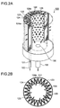
- FIGs. 2A and 2B are schematic configuration diagrams of the filter part included in the hydraulic device according to one embodiment of the present invention.
- the filter part 120 included in the hydraulic device 100 of the present embodiment includes a filter element 124 having a fine mesh shape and a filter core part 126, both disposed within a casing 123 having a substantially cylindrical shape.
- the filter element 124 is formed of soft non-woven fabric or the like having fine mesh openings 124a of approximately 0.025 micron. As illustrated in FIG. 2A , the filter element 124 is disposed so as to cover the periphery of the filter core part 126 in a zigzag fashion, for the purpose of increasing the density of the filtering function. Further, as illustrated in FIG. 2B , the filter element 124 includes a support part 129 of a mesh shape formed from a hard material such as plastic that supports the filter element 126 disposed inside the support part 129.
- the filter core part 126 is a substantially cylindrical member formed from a hard material such as metal, including aluminum, stainless steel and a sintered material.
- a plurality of filter pores 128 larger in size than the mesh openings 124a of the filter element 124 is formed on a wall surface 126a of the filter core part 126.
- the filter part 120 is a device having a unidirectional filtering performance from outside to inside, and including the filter element 126 of a mesh shape mounted to the outer side of the filter support part 126 on which the less-fine filter pores 128 are formed.
- high-pressure oil introduced from an introduction inlet 122 of an introduction part 121 for high-pressure oil is introduced through a clearance part 125 between the casing 123 and the filter element 124.
- the high-pressure oil is filtered from the filter element 124 disposed at the outer side toward the filter core part 126 disposed at the inner side.
- the soft filter element 126 is supported by the support part 129, so that the filter element 126 does not get damaged, for instance, by being stretched.
- the inside of the filter core part 126 becomes an oil channel 127, and a discharge part 130 capable of discharging oil filtered by the filter element 124 is disposed at the lower part of the oil channel 127, so that the filtered oil is discharged to the high-pressure oil channel L1 via a discharge pipe 132.
- the filter part 120 is a unidirectional filter device that has a filtering function from the outside of the filter element 124 toward the inside of the filter core part 126.
- the check valve 110 is disposed at the downstream side of the filter part 120 so as to be capable of preventing a backflow toward the filter part 120.
- providing the check valve 110 to prevent breakage and functional deterioration of the filter element 126 of the filter part 120 makes it possible to maintain the filtering function of the filter part 120 at the high-pressure oil side. Further, it is possible to improve the reliability of a plant that includes a prime mover having a servomotor, a control device or the like by preventing a foreign matter from entering the control device or the like.
Landscapes
- Engineering & Computer Science (AREA)
- Physics & Mathematics (AREA)
- Fluid Mechanics (AREA)
- Mechanical Engineering (AREA)
- General Engineering & Computer Science (AREA)
- Chemical & Material Sciences (AREA)
- Analytical Chemistry (AREA)
- Fluid-Pressure Circuits (AREA)
- Supply Devices, Intensifiers, Converters, And Telemotors (AREA)
- General Details Of Gearings (AREA)
- Control Of Transmission Device (AREA)
Abstract
Description
- The present invention relates to a hydraulic device capable of supplying oil to both of a high-pressure oil channel and a low-pressure oil channel from a common supply pump, and a prime mover device having the hydraulic device.
- Among servomotors and control devices used in various prime movers such as a gas turbine and a steam turbine, some of the known types are hydraulically controlled. A hydraulic device used for the hydraulic control includes a low-pressure oil channel for supplying low-pressure oil which is to be used as lubricant oil for a bearing or the like of a turbine and a high-pressure oil channel for supplying high-pressure oil which is to be used in the hydraulic control of a servomotor, a control device, or the like. As such a hydraulic device, Patent Literature 1 discloses a hydraulic device which is capable of supplying oil discharged from a supply pump to a high-pressure oil channel, as well as accumulating pressure of the high-pressure oil channel in an accumulator when, for instance, the supply pump is stopped.
- Patent Literature 1:
JP2004-156537A - When oil is supplied from a tank via a supply pump to a high-pressure oil channel which is a system of high-pressure oil supplied to a control device, it is necessary to remove impure substances such as dust to prevent the high-pressure oil channel from being clogged with the impure substances to cause deterioration of the performance of the hydraulic control. Thus, as illustrated in
FIG. 3 , aunidirectional filter part 16 having a filtering performance in direction A1 in which high-pressure oil is supplied is disposed at the input-stage side of a high-pressure oil channel 14 of ahydraulic device 10. Here, as illustrated inFIG. 3 , in thehydraulic device 10 having two systems of the high-pressure oil channel 14 and a low-pressure oil channel 20, anaccumulator 18 is disposed at the downstream side of thefilter part 16. Thus, when thesupply pump 12 is stopped, theaccumulator 18 starts operating and oil flows through the high-pressure oil channel 14, and the oil also flows in a direction of the low-pressure oil channel 20 (direction B1 inFIG. 3 ), the flow of the oil here being opposite to the normal flow direction of the oil. As a result, a counter pressure is applied to thefilter part 16, which may result in breakage of a filter element having a mesh shape included in thefilter part 16. - Patent Literature 1 discloses a hydraulic device capable of supplying oil discharged from an oil supply pump to a high-pressure oil channel, and accumulating pressure of the high-pressure oil channel in an accumulator. However, Patent Literature 1 does not mention prevention of breakage of a unidirectional filter part for high-pressure oil in a configuration including two systems of a high-pressure oil channel and a low-pressure oil channel as illustrated in
FIG. 3 . - The present invention was made in view of the above problem. An object of the invention is to provide a novel and improved hydraulic device capable of preventing breakage of a filter part for high-pressure oil, and a prime mover device including the hydraulic device.
- An aspect of the present invention is a hydraulic device configured to supply oil to a high-pressure oil channel and a low-pressure oil channel from an oil tank via a supply pump. The hydraulic device includes: an accumulator capable of accumulating a hydraulic pressure of the oil supplied to the high-pressure oil channel from the supply pump; a filter part disposed between the supply pump and a connection point at which the high-pressure oil channel connects to the accumulator, along a direction in which the oil is supplied; and a check valve capable of preventing a backflow of the oil to the filter part, and disposed between the filter part and the connection point.
- According to one aspect of the present invention, since the check valve capable of preventing a backflow of the oil to the filter part is disposed between the filter part and the connection point at which the high-pressure oil channel connects to the accumulator, it is possible to prevent the oil from flowing backward toward the filter part to damage the filter part when, for instance, the supply pump is stopped.
- In this case, in one aspect of the present invention, the filter part may include: an introduction part for introducing the oil supplied from the supply pump; a filter element having a mesh shape capable of filtering the oil introduced from the introduction part; a filter core part which is formed from a hard material in a substantially cylindrical shape and which includes a wall surface surrounded by the filter element, the wall surface including filter pores larger in size than mesh openings of the filter element; and a discharge part connected to an inside of the filter core part, the discharge part being capable of discharging the oil filtered by the filter element.
- In this way, it is possible to prevent the oil from flowing backward toward the filter part to damage the filter element of the filter part when, for instance, the supply pump is stopped.
- Further, in one aspect of the present invention, the high-pressure oil channel may include a high-pressure-side relief valve configured to be opened if a hydraulic pressure of the high-pressure oil channel is a predetermined value or more. The low-pressure oil channel may include a low-pressure-side relief valve configured to be opened if a hydraulic pressure of the low-pressure oil channel is a predetermined value or more. Further, a relief side of each of the high-pressure-side relief valve and the low-pressure-side relief valve may be connected to the oil tank.
- Thus, it is possible to prevent breakage of the filter part by stopping a backflow toward the filter part for a hydraulic device capable of supplying oil to the high-pressure oil channel and the low-pressure oil channel with the common oil tank and supply pump.
- Further, in another aspect of the present invention, a prime mover device includes a control device including the hydraulic device according to any one of the above.
- According to the other aspect of the present invention, breakage of the unidirectional filter part for high-pressure oil is prevented, which improves the reliability of the control device equipped with the hydraulic device.
- As described above, according to the present invention, breakage of the unidirectional filter part for high-pressure oil is prevented. Thus, reliability of the control device equipped with the hydraulic device is improved.
-
-
FIG. 1 is a schematic configuration diagram of one embodiment of a hydraulic device according to the present invention. -
FIGs. 2A and 2B are schematic configuration diagrams of a filter part included in one embodiment of a hydraulic device according to the present invention. -
FIG. 3 is a schematic configuration diagram of one embodiment of a conventional hydraulic device. - A preferred embodiment of the present invention will now be described in detail. It is intended, however, that the following embodiment does not unduly limit the present invention described in the claims, and not all configurations described in the embodiment are necessarily required as a solution of the present invention.
- First, a configuration of the hydraulic device according to one embodiment of the present invention will be described with reference to the drawings.
FIG. 1 is a schematic configuration diagram of one embodiment of a hydraulic device according to the present invention. - A
hydraulic device 100 of the present embodiment is a hydraulic device capable of supplying oil to a high-pressure oil channel L1 and a low-pressure oil channel L2 with acommon oil tank 102 and acommon supply pump 104. In the present embodiment, thehydraulic device 100 includes a high-pressure oil channel L1 and a low-pressure oil channel L2, as well as acheck valve 110 for stopping a backflow toward afilter part 120 disposed in the high-pressure oil channel L1 to prevent breakage of thefilter part 120. - The
hydraulic device 100 supplies high-pressure oil having a hydraulic pressure of approximately 10kg/cm2 as working oil for hydraulically controlling a device that is hydraulically controlled, which is a servomotor or a control device used in various prime movers (prime mover devices) such as a gas turbine and a steam turbine. Specifically, high-pressure oil is supplied to the high-pressure oil channel L1 (high-pressure oil system) which supplies high-pressure oil being working oil used in hydraulic control of a servomotor, a control device or the like from theoil tank 102 by thesupply pump 104, via an oil channel L4 including acheck valve 105. Thecheck valve 105 is a one-way valve that opens when pressurized oil flows from thesupply pump 104 toward the oil channel L1 and that closes so as to prevent a flow of pressurized oil that is opposite to the flow toward the oil channel L1. - Further, in the present embodiment, an
auxiliary pump 108 that serves as a backup pump in case of a malfunction or the like of thesupply pump 104 is provided. Theauxiliary pump 108 makes it possible to supply the high-pressure oil to the high-pressure oil channel L1 (high-pressure oil system) from theoil tank 102 via an oil channel L5 including acheck valve 109, as a backup pump for thesupply pump 104 being a main oil pump in case of a malfunction of thesupply pump 104. - An
accumulator 106 capable of accumulating hydraulic pressure of oil supplied from thesupply pump 102 is connected to the high-pressure oil channel L1. As conventionally known, theaccumulator 106 includes an accumulating chamber and a back-pressure chamber divided by a piston or an elastic expanding member so as to be fluid-tight. Theaccumulator 106 is configured such that the capacity of the accumulating chamber increases as a result of movement of the piston or expansion of the elastic expanding member when the pressure in the accumulating chamber exceeds the pressure in the back-pressure chamber, so as to accumulate hydraulic pressure in the accumulating chamber. In this way, it is possible to adjust the set minimum pressure at which pressure begins to be accumulated in the accumulating chamber by controlling the pressure of the back-pressure chamber. In the present embodiment, theaccumulator 106 is capable of accumulating hydraulic pressure of approximately 8kg/cm2. - Further, a high-pressure-
side relief valve 130 is disposed in the high-pressure oil channel L1 as illustrated inFIG. 1 . The high-pressure-side relief valve 130 is opened when the hydraulic pressure of the high-pressure oil channel L1 reaches a predetermined value or more. The high-pressure-side relief valve 130 includes avalve body 132 that opens and closes a port similarly to a conventionally known valve body, and aspring 134 that applies a force to press thevalve body 132 against a valve seat (not illustrated). - Specifically, the high-pressure-
side relief valve 130 is configured such that thevalve body 132 is pressed against the valve seat so as to close the port when the hydraulic pressure of the high-pressure oil channel L1 is less than a predetermined pressure, and such that thevalve body 132 moves against the force of thespring 134 so as to open the port when the hydraulic pressure of the high-pressure oil channel L1 is not less than the predetermined pressure, so that the pressurized oil in the high-pressure oil channel L1 is drained to theoil tank 102. Thus, with the function of the high-pressure-side relief valve 130, it is possible to prevent the hydraulic pressure of the high-pressure oil channel L1 from becoming the predetermined pressure set in advance or more. In the present embodiment, the high-pressure-side relief valve 130 is set so that the hydraulic pressure of the high-pressure oil channel L1 does not reach 10kg/cm2 or more. - Besides the high-pressure oil channel L1 (high-pressure oil system) for supplying high-pressure oil which is to be used in the hydraulic control of a servomotor, a control device or the like, the
hydraulic device 100 includes the low-pressure oil channel L2 (bearing oil system) for supplying low-pressure oil which is to be used as lubricant oil for a bearing of a turbine or the like. Specifically, low-pressure oil is supplied to the low-pressure oil channel L2 by thesupply pump 104 from theoil tank 102 via the oil channel L4 including thecheck valve 105. - The low-pressure oil channel L2 includes a
check valve 112 at the entry side which is a one-way valve that opens when oil flows from thesupply pump 104 toward the low-pressure oil channel L2 and that closes so as to prevent a flow of pressurized oil that is opposite to the flow toward the low-pressure oil channel L2. Further, at the exit side of thecheck valve 112 of the low-pressure oil channel L2, a hydraulic-pressure adjustment valve 114 for adjusting the hydraulic pressure of the oil to be a predetermined pressure or less is disposed. In the present embodiment, the hydraulic-pressure adjustment valve 114 adjusts the hydraulic pressure of the low-pressure oil channel L2 to 1.2kg/cm2. - Further, a low-pressure-
side relief vale 140 is disposed in the low-pressure oil channel L2, as illustrated inFIG. 1 . The low-pressure-side relief valve 140 is opened when the hydraulic pressure of the low-pressure oil channel L2 reaches a predetermined value or more. The low-pressure-side relief valve 140 includes avalve body 142 that opens and closes a port similarly to a conventionally known valve body, and aspring 144 which applies a force to press thevalve body 142 against a valve seat (not illustrated). In the present embodiment, the low-pressure-side relief valve 140 is set so that the hydraulic pressure of the low-pressure oil channel L2 does not exceed 1.2kg/cm2, and configured such that thevalve body 142 moves against the force of thespring 144 so as to open the port when the hydraulic pressure of the low-pressure oil channel L2 reaches 1.2kg/cm2 or more, so that the pressurized oil in the low-pressure oil channel L2 is drained to theoil tank 102. - Further, in the present embodiment, the high-pressure oil channel L1 includes a
filter part 120 for filtering out impure substances such as dust at the entry side of the high-pressure oil channel L1 for the purpose of removing impure substances when oil is supplied from theoil tank 102 by thesupply pump 104. Thefilter part 120 is a unidirectional filter device disposed between thesupply pump 104 and a connection point N1 at which the high-pressure oil channel L1 connects to theaccumulator 106. Thefilter part 120 has a filtering function in the direction in which oil is supplied to the high-pressure oil channel L1. The configuration of thefilter part 120 will be described below in detail. - Further, in the present embodiment, a
check valve 110 capable of preventing a backflow of oil to thefilter part 120 is disposed between thefilter part 120 and the connection point at which theaccumulator 106 connects to the high-pressure oil channel L1. Specifically, the high-pressure oil is prevented from flowing backward in a direction opposite to the forward direction from thesupply pump 104 toward the high-pressure oil channel L1, so that breakage of thefilter part 120 is prevented. - In the present embodiment, the
auxiliary pump 108 which serves as a backup pump in case of a malfunction of thesupply pump 104 being a main oil pump is also provided. Thehydraulic device 100 of the present embodiment is capable of supplying oil discharged from thesupply pump 104 to both of the high-pressure oil channel L1 and the low-pressure oil channel L2, and includes theaccumulator 106 capable of accumulating pressure of the high-pressure oil channel L1 when thesupply pump 104 is stopped, for instance. - Further, as there is a risk that a
bladder 106a of a rubber-balloon shape in theaccumulator 106 gets damaged by a foreign matter contained in the oil discharged from thesupply pump 104, the filter part (high-pressure oil filter) 120 needs to be disposed between thesupply pump 104 and theaccumulator 106. While the high-pressure oil discharged from thesupply pump 104 being a main oil pump is used in the high-pressure oil system L1 and the bearing-oil system L2, for instance, the high-pressure oil system L1 has a pressure of 0kg/cm2, and the bearing-oil system L2 has a pressure of 1.2kg/cm2. - Thus, in a case where no
check valve 110 is disposed at the downstream side of thefilter part 120, there is a risk that theaccumulator 106 starts operating to prevent a decrease in the high-pressure oil pressure when thesupply pump 104 is switched to or from theauxiliary pump 109, which may cause the oil to flow not only to the high-pressure oil system L1 from the connection point N1 but also toward the low-pressure oil channel L2 from the high-pressure oil system L1 via the check valve 112 (backflow), thereby damaging the filter part having a unidirectional filtering function. In view of this, thecheck valve 110 is disposed on the outlet side of thefilter part 120 serving as a high-pressure oil filter in order to stop a backflow of oil toward the low-pressure oil channel L2 from the high-pressure oil system L1 to prevent breakage of thefilter part 120. - Further, as in the present embodiment, with regard to the
hydraulic device 100 capable of supplying oil to the high-pressure oil channel L1 and the low-pressure oil channel L2 with thecommon oil tank 102 and thecommon supply pump 104, there is a risk that oil flows backward in a direction opposite to the forward direction in which thefilter part 120 has a filtering performance when, for instance, thesupply pump 104 is stopped, as described above. Thus, thecheck valve 110 is disposed at the downstream side of thefilter part 120 disposed in the high-pressure oil channel L1 to stop a backflow toward thefilter part 120, thereby preventing breakage of the filter part. - Next, the configuration of the filter part included in the hydraulic device according to one embodiment of the present invention will be described with reference to the drawings.
FIGs. 2A and 2B are schematic configuration diagrams of the filter part included in the hydraulic device according to one embodiment of the present invention. - As illustrated in
FIG. 2A , thefilter part 120 included in thehydraulic device 100 of the present embodiment includes afilter element 124 having a fine mesh shape and afilter core part 126, both disposed within acasing 123 having a substantially cylindrical shape. - The
filter element 124 is formed of soft non-woven fabric or the like havingfine mesh openings 124a of approximately 0.025 micron. As illustrated inFIG. 2A , thefilter element 124 is disposed so as to cover the periphery of thefilter core part 126 in a zigzag fashion, for the purpose of increasing the density of the filtering function. Further, as illustrated inFIG. 2B , thefilter element 124 includes asupport part 129 of a mesh shape formed from a hard material such as plastic that supports thefilter element 126 disposed inside thesupport part 129. - Furthermore, the
filter core part 126 is a substantially cylindrical member formed from a hard material such as metal, including aluminum, stainless steel and a sintered material. A plurality of filter pores 128 larger in size than themesh openings 124a of thefilter element 124 is formed on awall surface 126a of thefilter core part 126. Specifically, thefilter part 120 is a device having a unidirectional filtering performance from outside to inside, and including thefilter element 126 of a mesh shape mounted to the outer side of thefilter support part 126 on which the less-fine filter pores 128 are formed. - With the
filter part 120 having the above configuration, high-pressure oil introduced from anintroduction inlet 122 of anintroduction part 121 for high-pressure oil is introduced through aclearance part 125 between thecasing 123 and thefilter element 124. In this way, as illustrated inFIGs. 2A and 2B , the high-pressure oil is filtered from thefilter element 124 disposed at the outer side toward thefilter core part 126 disposed at the inner side. Further, when the filtering is performed in the forward direction, thesoft filter element 126 is supported by thesupport part 129, so that thefilter element 126 does not get damaged, for instance, by being stretched. - Further, the inside of the
filter core part 126 becomes anoil channel 127, and adischarge part 130 capable of discharging oil filtered by thefilter element 124 is disposed at the lower part of theoil channel 127, so that the filtered oil is discharged to the high-pressure oil channel L1 via adischarge pipe 132. Specifically, in the present embodiment, thefilter part 120 is a unidirectional filter device that has a filtering function from the outside of thefilter element 124 toward the inside of thefilter core part 126. - In case high-pressure oil flows backward into the
filter part 120 having the above configuration, i.e., in case high-pressure oil flows from the inside of thefilter core part 126 to the outside of thefilter element 124, there is a risk that thefilter element 126 formed of a soft material contracted in a zigzag shape expands to be torn apart. Further, even if thefilter element 126 does not go as far as getting damaged, thefilter element 126 may be expanded like a balloon until themesh openings 124a of thefilter element 126 get enlarged, which deteriorates the filtering performance from then on. - In view of this, in the present embodiment, to prevent breakage or functional deterioration of the
filter part 120 having a unidirectional filtering function with the above configuration, thecheck valve 110 is disposed at the downstream side of thefilter part 120 so as to be capable of preventing a backflow toward thefilter part 120. In this way, providing thecheck valve 110 to prevent breakage and functional deterioration of thefilter element 126 of thefilter part 120 makes it possible to maintain the filtering function of thefilter part 120 at the high-pressure oil side. Further, it is possible to improve the reliability of a plant that includes a prime mover having a servomotor, a control device or the like by preventing a foreign matter from entering the control device or the like. - The embodiment of the present invention has been described in detail above, but the present invention is not limited thereto, and one skilled in the art would readily understand that various modifications may be implemented within a scope that does not substantially depart from the novel features and advantageous effects of the present invention. Thus, such modifications are all included in the scope of the present invention.
- For instance, if a term is described along with another term that has a wider or similar meaning at least once in the present specification or drawings, the term can be paraphrased by the other term at any part of the specification or the drawings. Further, the configuration and operation of the hydraulic device are not limited to those described in the embodiment of the present invention, and may be modified in various ways when implemented.
-
- 100
- Hydraulic device
- 102
- Oil tank
- 104
- Supply pump
- 106
- Accumulator
- 108
- Auxiliary pump
- 110
- Check valve
- 120
- Filter part
- 121
- Introduction part
- 122
- Introduction inlet
- 123
- Casing
- 124
- Filter element
- 124a
- Mesh opening
- 125
- Clearance part
- 126
- Filter core part
- 126
- Wall surface
- 127
- Oil channel
- 128
- Filter pore
- 129
- Support part
- 130
- High-pressure-side relief valve
- 140
- Low-pressure-side relief valve
- L1
- High-pressure oil channel
- L2
- Low-pressure oil channel
Claims (4)
- A hydraulic device configured to supply oil to a high-pressure oil channel and a low-pressure oil channel from an oil tank via a supply pump, the hydraulic device comprising:an accumulator capable of accumulating a hydraulic pressure of the oil supplied to the high-pressure oil channel from the supply pump;a filter part disposed between the supply pump and a connection point at which the high-pressure oil channel connects to the accumulator, along a direction in which the oil is supplied; anda check valve capable of preventing a backflow of the oil to the filter part, the check valve being disposed between the filter part and the connection point.
- The hydraulic device according to claim 1,
wherein the filter part includes:an introduction part for introducing the oil supplied from the supply pump;a filter element having a mesh shape capable of filtering the oil introduced from the introduction part;a filter core part which is formed from a hard material in a substantially cylindrical shape and which includes a wall surface surrounded by the filter element, the wall surface including filter pores larger in size than mesh openings of the filter element; anda discharge part connected to an inside of the filter core part, the discharge part being capable of discharging the oil filtered by the filter element. - The hydraulic device according to claim 1 or 2,
wherein the high-pressure oil channel includes a high-pressure-side relief valve configured to be opened if a hydraulic pressure of the high-pressure oil channel is a predetermined value or more,
wherein the low-pressure oil channel includes a low-pressure-side relief valve configured to be opened if a hydraulic pressure of the low-pressure oil channel is a predetermined value or more, and
wherein a relief side of each of the high-pressure-side relief valve and the low-pressure-side relief valve is connected to the oil tank. - A prime mover device comprising a control device including the hydraulic device according to any one of claims 1 to 3.
Applications Claiming Priority (2)
| Application Number | Priority Date | Filing Date | Title |
|---|---|---|---|
| JP2013069515A JP6177562B2 (en) | 2013-03-28 | 2013-03-28 | Hydraulic device and prime mover |
| PCT/JP2013/072863 WO2014155767A1 (en) | 2013-03-28 | 2013-08-27 | Hydraulic device and prime mover device |
Publications (3)
| Publication Number | Publication Date |
|---|---|
| EP2980419A1 true EP2980419A1 (en) | 2016-02-03 |
| EP2980419A4 EP2980419A4 (en) | 2016-11-23 |
| EP2980419B1 EP2980419B1 (en) | 2021-10-20 |
Family
ID=51622810
Family Applications (1)
| Application Number | Title | Priority Date | Filing Date |
|---|---|---|---|
| EP13880140.2A Not-in-force EP2980419B1 (en) | 2013-03-28 | 2013-08-27 | Hydraulic device and prime mover device |
Country Status (6)
| Country | Link |
|---|---|
| US (1) | US9797418B2 (en) |
| EP (1) | EP2980419B1 (en) |
| JP (1) | JP6177562B2 (en) |
| KR (1) | KR101773273B1 (en) |
| CN (1) | CN104995413B (en) |
| WO (1) | WO2014155767A1 (en) |
Cited By (1)
| Publication number | Priority date | Publication date | Assignee | Title |
|---|---|---|---|---|
| CN105840592A (en) * | 2016-05-12 | 2016-08-10 | 陈连萍 | Filtering method adopting working condition adaptive filtration, magnetization, rotating magnetic field and centrifugation |
Families Citing this family (24)
| Publication number | Priority date | Publication date | Assignee | Title |
|---|---|---|---|---|
| CN105020207B (en) * | 2015-06-16 | 2017-05-31 | 中国海洋石油总公司 | Dual redundant regulator with emergency decompression |
| CN105864212A (en) * | 2016-05-12 | 2016-08-17 | 王雅莉 | Filtering method adopting wave suppression, magnetization, adsorption and rotating magnetic field |
| CN105736523A (en) * | 2016-05-12 | 2016-07-06 | 徐燚超 | Oil filtering method adopting full-frequency-band filtering, magnetization, adsorption, rotary magnetic field and centrifuging |
| CN105971991A (en) * | 2016-05-12 | 2016-09-28 | 王雅莉 | Filtering method adopting filter, magnetization, adsorption and rotating magnetic field |
| CN105889212A (en) * | 2016-05-12 | 2016-08-24 | 浙江工业职业技术学院 | Oil filter based on full-band working condition self-adaptive filtration, electrification and centrifugation |
| CN105864198A (en) * | 2016-05-12 | 2016-08-17 | 陈连萍 | Filter method through utilizing variable structure working condition-self-adaptive filtering, magnetization, magnetic field and centrifugation |
| CN105909610A (en) * | 2016-05-12 | 2016-08-31 | 李�昊 | Oil filtering method adopting full-frequency-band filtering, electrification, separation, adsorption and rotating magnetic field |
| CN105864170A (en) * | 2016-05-12 | 2016-08-17 | 王雅莉 | Oil filtering method adopting variable structure filtration, electrification, separation and adsorption |
| CN105864197A (en) * | 2016-05-12 | 2016-08-17 | 谢阿招 | Filter using variable structure self-adaptive filtering, magnetization, magnetic field and centrifugation |
| CN105889216A (en) * | 2016-05-12 | 2016-08-24 | 王雅莉 | Filtering method adopting full-band variable-structure work condition self-adaptive filtering, adsorption and magnetic field |
| CN105909605A (en) * | 2016-05-12 | 2016-08-31 | 李�昊 | Filtering method based on variable-structure working condition self-adaptive type filtration, electrification and rotating magnetic field |
| CN105889194A (en) * | 2016-05-12 | 2016-08-24 | 张华芳 | Method for treating hydraulic oil by adopting electrification, separation, electric loop adsorption and rotating magnetic fields |
| CN105889209A (en) * | 2016-05-12 | 2016-08-24 | 浙江工业职业技术学院 | Filtering box based on full-band variable-structure filtration, electrification, separation and centrifugation |
| CN105889211A (en) * | 2016-05-12 | 2016-08-24 | 浙江工业职业技术学院 | Oil filtering method based on full-band filtration, electrification, separation and centrifugation |
| CN105889213A (en) * | 2016-05-12 | 2016-08-24 | 浙江工业职业技术学院 | Filtering method based on full-band variable-structure filtration, electrification, separation and centrifugation |
| CN105937519A (en) * | 2016-05-12 | 2016-09-14 | 王雅莉 | Oil filtering method adopting filter, electrification, separation and adsorption |
| CN105864181A (en) * | 2016-05-12 | 2016-08-17 | 绍兴文理学院 | Filtering method adopting wave suppression, magnetization and adsorption |
| CN105782168A (en) * | 2016-05-12 | 2016-07-20 | 徐燚超 | Filtering method adopting wave suppression, magnetization, adsorption, rotating magnetic field and centrifugation |
| CN105864176A (en) * | 2016-05-12 | 2016-08-17 | 王雅莉 | Oil filtering method adopting full-band work condition self-adaptive filtering, adsorption and rotating magnetic field |
| CN105864224A (en) * | 2016-05-12 | 2016-08-17 | 王雅莉 | Filtering method adopting variable structure working-condition self-adaption smoothing, electrification, separation and adsorption |
| US11708684B2 (en) | 2019-11-06 | 2023-07-25 | Caterpillar Inc. | Hydraulic tank |
| CN114109943B (en) * | 2021-12-08 | 2023-05-26 | 中冶南方工程技术有限公司 | Converter two-venturi throat hydraulic servo system |
| CN114876917A (en) * | 2022-05-27 | 2022-08-09 | 三一重型装备有限公司 | Online oil purifying system of heading machine and heading machine |
| JP7797338B2 (en) * | 2022-08-29 | 2026-01-13 | 株式会社東芝 | Hybrid Servo System |
Family Cites Families (23)
| Publication number | Priority date | Publication date | Assignee | Title |
|---|---|---|---|---|
| JPS50145778A (en) * | 1974-05-16 | 1975-11-22 | ||
| JPS5637701U (en) * | 1979-08-31 | 1981-04-10 | ||
| JPS5637701A (en) | 1979-09-04 | 1981-04-11 | Mitsubishi Electric Corp | Retrodirective array antenna |
| JPS63171703A (en) | 1987-01-09 | 1988-07-15 | Hitachi Ltd | Materials management method |
| JPS63171703U (en) * | 1987-04-30 | 1988-11-08 | ||
| JPH03128406U (en) * | 1990-04-10 | 1991-12-25 | ||
| KR100186911B1 (en) * | 1995-04-13 | 1999-03-20 | 구종철 | Apparatus for informing of replacement time of engine oil, filter of internal combustion engine |
| JPH09122999A (en) | 1995-11-07 | 1997-05-13 | Amada Co Ltd | Hydraulic circuit for double cylinder drive |
| JPH1054215A (en) * | 1996-08-14 | 1998-02-24 | Nippon Soken Inc | Hydraulic control device in lubrication circuit of internal combustion engine |
| JPH10328507A (en) * | 1997-05-29 | 1998-12-15 | Wako Sangyo Kk | Fluid filter |
| US6814409B2 (en) * | 2001-04-12 | 2004-11-09 | A-Dec, Inc. | Hydraulic drive system |
| JP2004156537A (en) | 2002-11-07 | 2004-06-03 | Nissan Motor Co Ltd | Compression ratio control device for internal combustion engine |
| JP4136790B2 (en) * | 2003-05-20 | 2008-08-20 | トヨタ自動車株式会社 | Hydraulic device |
| US7290389B2 (en) * | 2003-07-22 | 2007-11-06 | Eaton Corporation | Hydraulic drive system and improved filter sub-system therefor |
| JP4385752B2 (en) * | 2003-12-10 | 2009-12-16 | トヨタ自動車株式会社 | Transmission lubrication device |
| CN2898092Y (en) | 2006-03-10 | 2007-05-09 | 山东晨钟机械股份有限公司 | Disk heat disperser |
| DE102006042372A1 (en) * | 2006-09-08 | 2008-03-27 | Deere & Company, Moline | charger |
| DE102008038520A1 (en) * | 2008-08-20 | 2010-02-25 | Robert Bosch Gmbh | Device for providing a pressure for a hydraulic consumer and method for providing a pressure |
| CN102032121B (en) | 2009-09-25 | 2012-12-26 | 上海汇益控制系统股份有限公司 | Hydraulic braking system for megawatt fan |
| CN101983835A (en) | 2010-11-04 | 2011-03-09 | 路文忠 | Linear hydrostatic guideway leading hydraulic oil to circulate in closed oil circuit by sealing elements |
| GB2490320A (en) * | 2011-04-20 | 2012-10-31 | Bamford Excavators Ltd | Hydraulic circuit with back-up pressure system to prevent cavitation |
| CN202733127U (en) | 2012-07-13 | 2013-02-13 | 中国舰船研究设计中心 | Marine hydraulic valve on-off control hydraulic system |
| CN102962232B (en) * | 2012-11-23 | 2015-12-23 | 武汉华液传动制造有限公司 | High-voltage pulse turbulent flow pipeline rinse-system |
-
2013
- 2013-03-28 JP JP2013069515A patent/JP6177562B2/en not_active Expired - Fee Related
- 2013-08-27 EP EP13880140.2A patent/EP2980419B1/en not_active Not-in-force
- 2013-08-27 CN CN201380073150.9A patent/CN104995413B/en not_active Expired - Fee Related
- 2013-08-27 WO PCT/JP2013/072863 patent/WO2014155767A1/en not_active Ceased
- 2013-08-27 US US14/770,162 patent/US9797418B2/en active Active
- 2013-08-27 KR KR1020157022379A patent/KR101773273B1/en not_active Expired - Fee Related
Cited By (1)
| Publication number | Priority date | Publication date | Assignee | Title |
|---|---|---|---|---|
| CN105840592A (en) * | 2016-05-12 | 2016-08-10 | 陈连萍 | Filtering method adopting working condition adaptive filtration, magnetization, rotating magnetic field and centrifugation |
Also Published As
| Publication number | Publication date |
|---|---|
| KR20150108895A (en) | 2015-09-30 |
| EP2980419B1 (en) | 2021-10-20 |
| US9797418B2 (en) | 2017-10-24 |
| WO2014155767A1 (en) | 2014-10-02 |
| EP2980419A4 (en) | 2016-11-23 |
| JP2014190524A (en) | 2014-10-06 |
| JP6177562B2 (en) | 2017-08-09 |
| CN104995413B (en) | 2017-11-21 |
| CN104995413A (en) | 2015-10-21 |
| US20160010669A1 (en) | 2016-01-14 |
| KR101773273B1 (en) | 2017-08-31 |
Similar Documents
| Publication | Publication Date | Title |
|---|---|---|
| US9797418B2 (en) | Hydraulic device and prime mover device | |
| JP2014190524A5 (en) | ||
| US20050178443A1 (en) | Relief valve | |
| CN105526202B (en) | A kind of overflow valve with pressure regulation and security function | |
| EP2267304A3 (en) | Hydraulic system and method for operating a brake of a wind turbine | |
| US20080230317A1 (en) | Oil Circulation System For A Compressor | |
| CN101963079B (en) | Engine oil filter component for diesel engine | |
| DE10343212A1 (en) | Balghydraulikdruckspeicher | |
| DE102018110847A1 (en) | Pulsationsdämpfungssystem | |
| JP5666790B2 (en) | Flowing water detection device | |
| US6881330B2 (en) | Multi-stage EDM filter | |
| CN108474372B (en) | Pneumatically controlled drain valve | |
| KR20160141730A (en) | Damping device and slip-controllable vehicle brake system | |
| JP7499297B2 (en) | Hydraulic pressure supply device and hydraulic pressure supply method | |
| JP2012130827A (en) | Filtration accuracy variable filter | |
| EP4406637A1 (en) | Filtration device | |
| CN105121030B (en) | Unload die block | |
| CN210239889U (en) | fuel pump | |
| US10408235B2 (en) | Accumulator and fluid material discharge system | |
| JP3831802B2 (en) | Circuit breaker fluid pressure drive | |
| JP2014181685A (en) | Steam turbine plant | |
| CN212388665U (en) | Combined integrated booster pump station capable of keeping waterway unblocked when pump is stopped | |
| JP2014005963A (en) | Drain recovery system | |
| RU2670470C1 (en) | Control hydraulic system of steam turbine valves | |
| JP3171557U (en) | Hydraulic fuse |
Legal Events
| Date | Code | Title | Description |
|---|---|---|---|
| PUAI | Public reference made under article 153(3) epc to a published international application that has entered the european phase |
Free format text: ORIGINAL CODE: 0009012 |
|
| 17P | Request for examination filed |
Effective date: 20150811 |
|
| AK | Designated contracting states |
Kind code of ref document: A1 Designated state(s): AL AT BE BG CH CY CZ DE DK EE ES FI FR GB GR HR HU IE IS IT LI LT LU LV MC MK MT NL NO PL PT RO RS SE SI SK SM TR |
|
| AX | Request for extension of the european patent |
Extension state: BA ME |
|
| DAX | Request for extension of the european patent (deleted) | ||
| A4 | Supplementary search report drawn up and despatched |
Effective date: 20161020 |
|
| RIC1 | Information provided on ipc code assigned before grant |
Ipc: F15B 21/04 20060101AFI20161014BHEP Ipc: F15B 1/26 20060101ALI20161014BHEP Ipc: F15B 20/00 20060101ALI20161014BHEP |
|
| STAA | Information on the status of an ep patent application or granted ep patent |
Free format text: STATUS: EXAMINATION IS IN PROGRESS |
|
| 17Q | First examination report despatched |
Effective date: 20190207 |
|
| RAP1 | Party data changed (applicant data changed or rights of an application transferred) |
Owner name: MITSUBISHI POWER, LTD. |
|
| GRAP | Despatch of communication of intention to grant a patent |
Free format text: ORIGINAL CODE: EPIDOSNIGR1 |
|
| STAA | Information on the status of an ep patent application or granted ep patent |
Free format text: STATUS: GRANT OF PATENT IS INTENDED |
|
| INTG | Intention to grant announced |
Effective date: 20210719 |
|
| GRAS | Grant fee paid |
Free format text: ORIGINAL CODE: EPIDOSNIGR3 |
|
| GRAA | (expected) grant |
Free format text: ORIGINAL CODE: 0009210 |
|
| STAA | Information on the status of an ep patent application or granted ep patent |
Free format text: STATUS: THE PATENT HAS BEEN GRANTED |
|
| AK | Designated contracting states |
Kind code of ref document: B1 Designated state(s): AL AT BE BG CH CY CZ DE DK EE ES FI FR GB GR HR HU IE IS IT LI LT LU LV MC MK MT NL NO PL PT RO RS SE SI SK SM TR |
|
| REG | Reference to a national code |
Ref country code: GB Ref legal event code: FG4D |
|
| REG | Reference to a national code |
Ref country code: CH Ref legal event code: EP |
|
| REG | Reference to a national code |
Ref country code: DE Ref legal event code: R096 Ref document number: 602013079756 Country of ref document: DE |
|
| REG | Reference to a national code |
Ref country code: IE Ref legal event code: FG4D |
|
| REG | Reference to a national code |
Ref country code: AT Ref legal event code: REF Ref document number: 1440177 Country of ref document: AT Kind code of ref document: T Effective date: 20211115 |
|
| REG | Reference to a national code |
Ref country code: LT Ref legal event code: MG9D |
|
| REG | Reference to a national code |
Ref country code: NL Ref legal event code: MP Effective date: 20211020 |
|
| REG | Reference to a national code |
Ref country code: AT Ref legal event code: MK05 Ref document number: 1440177 Country of ref document: AT Kind code of ref document: T Effective date: 20211020 |
|
| PG25 | Lapsed in a contracting state [announced via postgrant information from national office to epo] |
Ref country code: RS Free format text: LAPSE BECAUSE OF FAILURE TO SUBMIT A TRANSLATION OF THE DESCRIPTION OR TO PAY THE FEE WITHIN THE PRESCRIBED TIME-LIMIT Effective date: 20211020 Ref country code: LT Free format text: LAPSE BECAUSE OF FAILURE TO SUBMIT A TRANSLATION OF THE DESCRIPTION OR TO PAY THE FEE WITHIN THE PRESCRIBED TIME-LIMIT Effective date: 20211020 Ref country code: FI Free format text: LAPSE BECAUSE OF FAILURE TO SUBMIT A TRANSLATION OF THE DESCRIPTION OR TO PAY THE FEE WITHIN THE PRESCRIBED TIME-LIMIT Effective date: 20211020 Ref country code: BG Free format text: LAPSE BECAUSE OF FAILURE TO SUBMIT A TRANSLATION OF THE DESCRIPTION OR TO PAY THE FEE WITHIN THE PRESCRIBED TIME-LIMIT Effective date: 20220120 Ref country code: AT Free format text: LAPSE BECAUSE OF FAILURE TO SUBMIT A TRANSLATION OF THE DESCRIPTION OR TO PAY THE FEE WITHIN THE PRESCRIBED TIME-LIMIT Effective date: 20211020 |
|
| PG25 | Lapsed in a contracting state [announced via postgrant information from national office to epo] |
Ref country code: IS Free format text: LAPSE BECAUSE OF FAILURE TO SUBMIT A TRANSLATION OF THE DESCRIPTION OR TO PAY THE FEE WITHIN THE PRESCRIBED TIME-LIMIT Effective date: 20220220 Ref country code: SE Free format text: LAPSE BECAUSE OF FAILURE TO SUBMIT A TRANSLATION OF THE DESCRIPTION OR TO PAY THE FEE WITHIN THE PRESCRIBED TIME-LIMIT Effective date: 20211020 Ref country code: PT Free format text: LAPSE BECAUSE OF FAILURE TO SUBMIT A TRANSLATION OF THE DESCRIPTION OR TO PAY THE FEE WITHIN THE PRESCRIBED TIME-LIMIT Effective date: 20220221 Ref country code: PL Free format text: LAPSE BECAUSE OF FAILURE TO SUBMIT A TRANSLATION OF THE DESCRIPTION OR TO PAY THE FEE WITHIN THE PRESCRIBED TIME-LIMIT Effective date: 20211020 Ref country code: NO Free format text: LAPSE BECAUSE OF FAILURE TO SUBMIT A TRANSLATION OF THE DESCRIPTION OR TO PAY THE FEE WITHIN THE PRESCRIBED TIME-LIMIT Effective date: 20220120 Ref country code: NL Free format text: LAPSE BECAUSE OF FAILURE TO SUBMIT A TRANSLATION OF THE DESCRIPTION OR TO PAY THE FEE WITHIN THE PRESCRIBED TIME-LIMIT Effective date: 20211020 Ref country code: LV Free format text: LAPSE BECAUSE OF FAILURE TO SUBMIT A TRANSLATION OF THE DESCRIPTION OR TO PAY THE FEE WITHIN THE PRESCRIBED TIME-LIMIT Effective date: 20211020 Ref country code: HR Free format text: LAPSE BECAUSE OF FAILURE TO SUBMIT A TRANSLATION OF THE DESCRIPTION OR TO PAY THE FEE WITHIN THE PRESCRIBED TIME-LIMIT Effective date: 20211020 Ref country code: GR Free format text: LAPSE BECAUSE OF FAILURE TO SUBMIT A TRANSLATION OF THE DESCRIPTION OR TO PAY THE FEE WITHIN THE PRESCRIBED TIME-LIMIT Effective date: 20220121 Ref country code: ES Free format text: LAPSE BECAUSE OF FAILURE TO SUBMIT A TRANSLATION OF THE DESCRIPTION OR TO PAY THE FEE WITHIN THE PRESCRIBED TIME-LIMIT Effective date: 20211020 |
|
| REG | Reference to a national code |
Ref country code: DE Ref legal event code: R097 Ref document number: 602013079756 Country of ref document: DE |
|
| PG25 | Lapsed in a contracting state [announced via postgrant information from national office to epo] |
Ref country code: SM Free format text: LAPSE BECAUSE OF FAILURE TO SUBMIT A TRANSLATION OF THE DESCRIPTION OR TO PAY THE FEE WITHIN THE PRESCRIBED TIME-LIMIT Effective date: 20211020 Ref country code: SK Free format text: LAPSE BECAUSE OF FAILURE TO SUBMIT A TRANSLATION OF THE DESCRIPTION OR TO PAY THE FEE WITHIN THE PRESCRIBED TIME-LIMIT Effective date: 20211020 Ref country code: RO Free format text: LAPSE BECAUSE OF FAILURE TO SUBMIT A TRANSLATION OF THE DESCRIPTION OR TO PAY THE FEE WITHIN THE PRESCRIBED TIME-LIMIT Effective date: 20211020 Ref country code: EE Free format text: LAPSE BECAUSE OF FAILURE TO SUBMIT A TRANSLATION OF THE DESCRIPTION OR TO PAY THE FEE WITHIN THE PRESCRIBED TIME-LIMIT Effective date: 20211020 Ref country code: DK Free format text: LAPSE BECAUSE OF FAILURE TO SUBMIT A TRANSLATION OF THE DESCRIPTION OR TO PAY THE FEE WITHIN THE PRESCRIBED TIME-LIMIT Effective date: 20211020 Ref country code: CZ Free format text: LAPSE BECAUSE OF FAILURE TO SUBMIT A TRANSLATION OF THE DESCRIPTION OR TO PAY THE FEE WITHIN THE PRESCRIBED TIME-LIMIT Effective date: 20211020 |
|
| PLBE | No opposition filed within time limit |
Free format text: ORIGINAL CODE: 0009261 |
|
| STAA | Information on the status of an ep patent application or granted ep patent |
Free format text: STATUS: NO OPPOSITION FILED WITHIN TIME LIMIT |
|
| 26N | No opposition filed |
Effective date: 20220721 |
|
| PG25 | Lapsed in a contracting state [announced via postgrant information from national office to epo] |
Ref country code: AL Free format text: LAPSE BECAUSE OF FAILURE TO SUBMIT A TRANSLATION OF THE DESCRIPTION OR TO PAY THE FEE WITHIN THE PRESCRIBED TIME-LIMIT Effective date: 20211020 |
|
| PGFP | Annual fee paid to national office [announced via postgrant information from national office to epo] |
Ref country code: DE Payment date: 20220621 Year of fee payment: 10 |
|
| PG25 | Lapsed in a contracting state [announced via postgrant information from national office to epo] |
Ref country code: SI Free format text: LAPSE BECAUSE OF FAILURE TO SUBMIT A TRANSLATION OF THE DESCRIPTION OR TO PAY THE FEE WITHIN THE PRESCRIBED TIME-LIMIT Effective date: 20211020 |
|
| PG25 | Lapsed in a contracting state [announced via postgrant information from national office to epo] |
Ref country code: MC Free format text: LAPSE BECAUSE OF FAILURE TO SUBMIT A TRANSLATION OF THE DESCRIPTION OR TO PAY THE FEE WITHIN THE PRESCRIBED TIME-LIMIT Effective date: 20211020 |
|
| REG | Reference to a national code |
Ref country code: CH Ref legal event code: PL |
|
| GBPC | Gb: european patent ceased through non-payment of renewal fee |
Effective date: 20220827 |
|
| PG25 | Lapsed in a contracting state [announced via postgrant information from national office to epo] |
Ref country code: LU Free format text: LAPSE BECAUSE OF NON-PAYMENT OF DUE FEES Effective date: 20220827 Ref country code: LI Free format text: LAPSE BECAUSE OF NON-PAYMENT OF DUE FEES Effective date: 20220831 Ref country code: CH Free format text: LAPSE BECAUSE OF NON-PAYMENT OF DUE FEES Effective date: 20220831 |
|
| REG | Reference to a national code |
Ref country code: BE Ref legal event code: MM Effective date: 20220831 |
|
| PG25 | Lapsed in a contracting state [announced via postgrant information from national office to epo] |
Ref country code: IT Free format text: LAPSE BECAUSE OF FAILURE TO SUBMIT A TRANSLATION OF THE DESCRIPTION OR TO PAY THE FEE WITHIN THE PRESCRIBED TIME-LIMIT Effective date: 20211020 |
|
| PG25 | Lapsed in a contracting state [announced via postgrant information from national office to epo] |
Ref country code: IE Free format text: LAPSE BECAUSE OF NON-PAYMENT OF DUE FEES Effective date: 20220827 Ref country code: FR Free format text: LAPSE BECAUSE OF NON-PAYMENT OF DUE FEES Effective date: 20220831 |
|
| PG25 | Lapsed in a contracting state [announced via postgrant information from national office to epo] |
Ref country code: BE Free format text: LAPSE BECAUSE OF NON-PAYMENT OF DUE FEES Effective date: 20220831 |
|
| PG25 | Lapsed in a contracting state [announced via postgrant information from national office to epo] |
Ref country code: GB Free format text: LAPSE BECAUSE OF NON-PAYMENT OF DUE FEES Effective date: 20220827 |
|
| REG | Reference to a national code |
Ref country code: DE Ref legal event code: R119 Ref document number: 602013079756 Country of ref document: DE |
|
| PG25 | Lapsed in a contracting state [announced via postgrant information from national office to epo] |
Ref country code: HU Free format text: LAPSE BECAUSE OF FAILURE TO SUBMIT A TRANSLATION OF THE DESCRIPTION OR TO PAY THE FEE WITHIN THE PRESCRIBED TIME-LIMIT; INVALID AB INITIO Effective date: 20130827 |
|
| PG25 | Lapsed in a contracting state [announced via postgrant information from national office to epo] |
Ref country code: CY Free format text: LAPSE BECAUSE OF FAILURE TO SUBMIT A TRANSLATION OF THE DESCRIPTION OR TO PAY THE FEE WITHIN THE PRESCRIBED TIME-LIMIT Effective date: 20211020 |
|
| PG25 | Lapsed in a contracting state [announced via postgrant information from national office to epo] |
Ref country code: MK Free format text: LAPSE BECAUSE OF FAILURE TO SUBMIT A TRANSLATION OF THE DESCRIPTION OR TO PAY THE FEE WITHIN THE PRESCRIBED TIME-LIMIT Effective date: 20211020 |
|
| PG25 | Lapsed in a contracting state [announced via postgrant information from national office to epo] |
Ref country code: DE Free format text: LAPSE BECAUSE OF NON-PAYMENT OF DUE FEES Effective date: 20240301 |
|
| PG25 | Lapsed in a contracting state [announced via postgrant information from national office to epo] |
Ref country code: MT Free format text: LAPSE BECAUSE OF FAILURE TO SUBMIT A TRANSLATION OF THE DESCRIPTION OR TO PAY THE FEE WITHIN THE PRESCRIBED TIME-LIMIT Effective date: 20211020 |
|
| PG25 | Lapsed in a contracting state [announced via postgrant information from national office to epo] |
Ref country code: TR Free format text: LAPSE BECAUSE OF FAILURE TO SUBMIT A TRANSLATION OF THE DESCRIPTION OR TO PAY THE FEE WITHIN THE PRESCRIBED TIME-LIMIT Effective date: 20211020 |