EP2980026A1 - Lifting apparatus, lifting set, and water treatment facility - Google Patents
Lifting apparatus, lifting set, and water treatment facility Download PDFInfo
- Publication number
- EP2980026A1 EP2980026A1 EP14774448.6A EP14774448A EP2980026A1 EP 2980026 A1 EP2980026 A1 EP 2980026A1 EP 14774448 A EP14774448 A EP 14774448A EP 2980026 A1 EP2980026 A1 EP 2980026A1
- Authority
- EP
- European Patent Office
- Prior art keywords
- lifting apparatus
- water treatment
- treatment device
- engaging portion
- engaging
- Prior art date
- Legal status (The legal status is an assumption and is not a legal conclusion. Google has not performed a legal analysis and makes no representation as to the accuracy of the status listed.)
- Granted
Links
Images




Classifications
-
- B—PERFORMING OPERATIONS; TRANSPORTING
- B66—HOISTING; LIFTING; HAULING
- B66C—CRANES; LOAD-ENGAGING ELEMENTS OR DEVICES FOR CRANES, CAPSTANS, WINCHES, OR TACKLES
- B66C1/00—Load-engaging elements or devices attached to lifting or lowering gear of cranes or adapted for connection therewith for transmitting lifting forces to articles or groups of articles
- B66C1/10—Load-engaging elements or devices attached to lifting or lowering gear of cranes or adapted for connection therewith for transmitting lifting forces to articles or groups of articles by mechanical means
- B66C1/62—Load-engaging elements or devices attached to lifting or lowering gear of cranes or adapted for connection therewith for transmitting lifting forces to articles or groups of articles by mechanical means comprising article-engaging members of a shape complementary to that of the articles to be handled
- B66C1/66—Load-engaging elements or devices attached to lifting or lowering gear of cranes or adapted for connection therewith for transmitting lifting forces to articles or groups of articles by mechanical means comprising article-engaging members of a shape complementary to that of the articles to be handled for engaging holes, recesses, or abutments on articles specially provided for facilitating handling thereof
-
- B—PERFORMING OPERATIONS; TRANSPORTING
- B01—PHYSICAL OR CHEMICAL PROCESSES OR APPARATUS IN GENERAL
- B01D—SEPARATION
- B01D61/00—Processes of separation using semi-permeable membranes, e.g. dialysis, osmosis or ultrafiltration; Apparatus, accessories or auxiliary operations specially adapted therefor
- B01D61/14—Ultrafiltration; Microfiltration
- B01D61/20—Accessories; Auxiliary operations
-
- B—PERFORMING OPERATIONS; TRANSPORTING
- B01—PHYSICAL OR CHEMICAL PROCESSES OR APPARATUS IN GENERAL
- B01D—SEPARATION
- B01D65/00—Accessories or auxiliary operations, in general, for separation processes or apparatus using semi-permeable membranes
-
- B—PERFORMING OPERATIONS; TRANSPORTING
- B66—HOISTING; LIFTING; HAULING
- B66C—CRANES; LOAD-ENGAGING ELEMENTS OR DEVICES FOR CRANES, CAPSTANS, WINCHES, OR TACKLES
- B66C1/00—Load-engaging elements or devices attached to lifting or lowering gear of cranes or adapted for connection therewith for transmitting lifting forces to articles or groups of articles
- B66C1/10—Load-engaging elements or devices attached to lifting or lowering gear of cranes or adapted for connection therewith for transmitting lifting forces to articles or groups of articles by mechanical means
-
- C—CHEMISTRY; METALLURGY
- C02—TREATMENT OF WATER, WASTE WATER, SEWAGE, OR SLUDGE
- C02F—TREATMENT OF WATER, WASTE WATER, SEWAGE, OR SLUDGE
- C02F1/00—Treatment of water, waste water, or sewage
- C02F1/44—Treatment of water, waste water, or sewage by dialysis, osmosis or reverse osmosis
-
- B—PERFORMING OPERATIONS; TRANSPORTING
- B01—PHYSICAL OR CHEMICAL PROCESSES OR APPARATUS IN GENERAL
- B01D—SEPARATION
- B01D2313/00—Details relating to membrane modules or apparatus
- B01D2313/56—Specific mechanisms for loading the membrane in a module
-
- B—PERFORMING OPERATIONS; TRANSPORTING
- B01—PHYSICAL OR CHEMICAL PROCESSES OR APPARATUS IN GENERAL
- B01D—SEPARATION
- B01D2313/00—Details relating to membrane modules or apparatus
- B01D2313/57—Tools used for removal of membranes
-
- B—PERFORMING OPERATIONS; TRANSPORTING
- B01—PHYSICAL OR CHEMICAL PROCESSES OR APPARATUS IN GENERAL
- B01D—SEPARATION
- B01D2315/00—Details relating to the membrane module operation
- B01D2315/06—Submerged-type; Immersion type
-
- C—CHEMISTRY; METALLURGY
- C02—TREATMENT OF WATER, WASTE WATER, SEWAGE, OR SLUDGE
- C02F—TREATMENT OF WATER, WASTE WATER, SEWAGE, OR SLUDGE
- C02F2201/00—Apparatus for treatment of water, waste water or sewage
- C02F2201/002—Construction details of the apparatus
-
- C—CHEMISTRY; METALLURGY
- C02—TREATMENT OF WATER, WASTE WATER, SEWAGE, OR SLUDGE
- C02F—TREATMENT OF WATER, WASTE WATER, SEWAGE, OR SLUDGE
- C02F2303/00—Specific treatment goals
- C02F2303/14—Maintenance of water treatment installations
Definitions
- the present invention relates to a lifting apparatus capable of engaging with and disengaging from a water treatment device which is to be lifted, a lifting set, and a water treatment facility.
- a water treatment device is typically provided with an eyebolt on an upper portion thereof, and disposing the water treatment device in a treatment tank requires a series of operations including engaging a hook of a lifting apparatus with the eyebolt, bringing up and down the lifting apparatus, and then disengaging the hook from the eyebolt.
- Patent Reference 1 discloses a lifting apparatus provided with a reference portion to be a reference for positioning the lifting apparatus within a treatment tank, where the lifting apparatus includes a main body portion capable of moving up and down along with a water treatment device, a coupling portion capable of engaging with and disengaging from a hanging portion of the water treatment device, and a positioning portion for positioning the main body portion to the reference portion so as to align the coupling portion with the hanging portion of the water treatment device.
- This lifting apparatus is to provide a lifting apparatus that can accurately operate a water treatment device from outside of a water tank when the water treatment device is immersed into the liquid and invisible from outside of the water tank.
- Patent Document 1 Japanese Patent Laid-Open Application No. 2001-255305
- an object of the present invention is to provide a lifting apparatus, a lifting set, and a water treatment facility in which cumbersome manual operations are not required to engage/disengage a water treatment device and a hanging tool with/from each other.
- a lifting apparatus capable of engaging with and disengaging from a water treatment device is to be lifted includes a frame, and an engaging portion pivotably attached to the frame by an upper portion thereof in a vertical position, where the engaging potion is capable of engaging with an engageable portion of the water treatment device, and that the engaging portion has a first operation state in which the engaging portion pivots by contacting the engageable portion as the lifting apparatus approaches the water treatment device from above, and then pivots back to the vertical position as the lifting apparatus further approaches the water treatment device to become closer thereto, whereby the engaging portion and the engageable portion become engageable with each other.
- the engaging portion of the lifting apparatus which is set on the frame in the first operation state abuts the engageable portion of the water treatment device so as to pivot around a supporting portion of the engaging portion, and when the lifting apparatus is further lowered, the abutment with the engageable portion is released and the engaging portion returns to the vertical position from the pivoting position.
- the engaging portion automatically engages with the engageable portion by this returning action to the vertical position. Accordingly, cumbersome manual operations for engagement are unnecessary, and the engaging state can be achieved by simply lowering the lifting apparatus toward the water treatment device from above.
- a second characteristic construction of the lifting apparatus in accordance with the present invention as described in claim 2 is, in addition to the first characteristic construction described above, that the engaging portion has a second operation state in addition to the first operation state, in which the engaging portion disengages from the engageable portion by its own weight or a biased force, when the lifting apparatus further approaches the water treatment device after the water treatment device has been installed into a predetermined position from a lifted state thereof lifted being by the lifting apparatus.
- the water treatment device when the water treatment device is lifted in such a condition that the engaging portion on the frame set in the second operation state is engaged with the engageable portion of the water treatment device, the water treatment device is transported to the predetermined position and lowered thereto so as to be installed, and then the lifting apparatus is further lowered to get closer to the water treatment device, the engaging portion is automatically released from the engageable portion by its own weight or the biased power. Accordingly, cumbersome manual operations for disengagement are unnecessary, and the disengaged state is achieved by simply making the lifting apparatus closer to the water treatment device.
- a third characteristic construction of the lifting apparatus in accordance with the present invention as described in claim 3 is that the first operation state and the second operation state are switched by changing a position to which the engaging portion is attached to the frame, or by attaching and releasing a biasing means to the engaging portion.
- the first operation state and the second operation state can be switched by a changing operation of the position to which the engaging portion is attached and supported, or by an attaching/releasing operation of the biasing means.
- the switching operation is easily achieved in accordance with the purpose: whether the water treatment device is to be lifted from a predetermined position, or to be installed in the predetermined position.
- a characteristic construction of the lifting set in accordance with the present invention as described in claim 4 is that the lifting set includes the lifting apparatus having one of the first to third characteristic constructions described above, and a water treatment device to be lifted by the lifting apparatus.
- a characteristic construction of the water treatment facility in accordance with the present invention as described in claim 5 is that it is provided with a lifting apparatus having any one of the first to third characteristic constructions described above, a water treatment device, and a tank body in which the water treatment device is immersed in liquid to be treated.
- a second characteristic construction of the water treatment facility in accordance with the present invention as described in claim 6 is, in addition to the first characteristic construction described above, that the water treatment device is a membrane separation device.
- a water treatment facility 1 includes a treatment tank 2 which is a tank body, a water treatment device 3 immersed in water to be treated filled in the treatment tank 2, and a lifting apparatus 4 for lifting the water treatment device 3.
- the water treatment device 3 is an immersion-type membrane separation device 3 having a membrane module in which a number of plate-shaped membrane elements are disposed in a casing having upper and lower openings such that respective membrane surfaces are vertically positioned and separated from one another by a predetermined distance provided therebetween, and a diffuser device disposed under the membrane module.
- the treatment tank 2 includes a plurality of membrane separation devices 3 immersed therein.
- a lifting apparatus 4 is also provided in order to lift up and transport the membrane separation device 3 in and out of the treatment tank 2 when a routine maintenance is conducted or a broken membrane element is replaced. It should be noted that, although the present embodiment will be explained in such a case where the water treatment device 3 is an immersion-type membrane separation device 3, the water treatment device 3 to be lifted by the lifting apparatus 4 in accordance with the present invention is not limited to a membrane separation device, and the present invention is applicable to any water treatment device submersed in water, such as a submersible pump.
- a pair of guide bars 8 are provided for each of the membrane separation devices 3 and fixed to the bottom of the treatment tank 2 so as to stand upright and position the membrane separation device 3 which is immersed therein by engaging with the guide bars 8 by guided portions 30 thereof provided on respective side walls of the membrane separation device 3.
- the pair of guide bars 8 are disposed in the vicinity of a pair of diagonal corners of the membrane separation device 3 in plan view.
- the guided portions 30 are provided on upper portion of side walls facing the respective guide bars 8.
- Each of the guided portions 30 has a pair of plate-shaped protrusions so as to hold the corresponding guide bar 8 from both sides.
- the lifting apparatus 4 is hanging from a lifting equipment 6 such as a hoist crane via a cable body 5 such as a sling belt or chain so as to be freely raised and lowered.
- the lifting equipment 6 is supported by a rail 7 provided thereabove so as to be movable along the rail 7 in a horizontal direction.
- the lifting apparatus 4 includes a frame formed of a pair of side frames 42 made of steel plates, and a center frame 43 connecting the side frames 42.
- Each of the engaging portions 44 is attached vertically to the side frames 42 with a pivot pin P such that an upper portion thereof is rotatable.
- Each of the engaging portions 44 has two elongated plate members lower portions of which are connected via an engaging pin which engages with the engageable portion 32 of the water treatment device 3, while upper portions of which are rockably attached to the side frame 42 with the pivot pin P.
- the pivot pin P has a screw portion formed at an end thereof so as to be fastened by a nut.
- each of the side frames 42 has a pair of holes 47 and 48 on each side portion thereof, to which the engaging portion 44 can be attached, as shown in FIG. 3C .
- the engaging portion 44 is set to the first operation state when it is attached by inserting the pivot pin P into the inner-side hole 48, while it is set to the second operation state when it is attached by inserting the pivot pin P into the outer-side hole 47.
- the engaging portion 44 is configured such that the mounting state thereof is changeable between the first operation state and the second operation sate.
- the center frame 43 has an attaching member 46 provided at a center portion thereof, to which the cable body 5 coupling to the lifting equipment 6 is attached.
- Each of the side frames 42 has a guided portion 40 provided on one side thereof, which engages with a corresponding one of the guide bars 8.
- the guided portion 40 also has a pair of plate-shaped protrusions so as to hold the guide bar 8 therebetween.
- the lifting equipment 6 When the membrane separation device 3 immersed in the treatment tank 2 is to be taken out therefrom, the lifting equipment 6 is extended so as to lower and position the lifting apparatus 4 which is set to the first operation state by attaching the engaging portion 44 to the inner-side hole 48 such that the each of the guided portions 40 engages with the corresponding guide bars 8.
- each of the engaging portions 44 of the lifting apparatus 4 becomes in contact with the respective engageable portion 32 of the membrane separation device 3 from above as shown in FIG. 4A , and when the lifting apparatus 4 is further lowered, each engaging portion 44 rocks outwardly along a slope portion 32a of the corresponding engageable portion 32 as shown in FIG. 4B . That is, each engaging portion 44 pivots around the pivot pin P thereof.
- each of the engaging portions 44 passes the sloped portion 32a of the engageable portion 32 and pivots around the pivot pin P so as to return to its vertical position, whereby the engaging pin of the engaging portion 44 and the engageable portion 32 become engageable with each other.
- the membrane separation device 3 is lifted up from the treatment tank 2 as shown in FIG. 4D .
- the engaging portion 44 is first attached to the outer-side whole 47 of the lifting apparatus 4 so as to be set to the second operation state, and then the lifting equipment 6 is wound up so as to raise the lifting apparatus 4 in a state in which the engaging pin of the engaging portion 44 of the lifting apparatus 4 and the engageable portion 32 of the membrane separation device 3 are engaged with each other.
- the lifting apparatus 4 is transported to a predetermined location along the rail 7 and positioned such that the guided portions 30 of the membrane separation device 3 engage with the corresponding guide bars 8 standing in the treatment tank 2.
- the lifting equipment 6 is extended so as to lower the lifting apparatus 4, whereby the membrane separation device 3 is disposed in the treatment tank 2 and immersed therein.
- the engaging portion 44 is disengaged from the engageable portion 32 by its weight.
- the first operation state is set when the engaging portions 44 are attached to the respective side frames 42 by inserting the pivot pin P into the inner-side hole 48
- the second operation state is set when the engaging portions 44 are attached by inserting the pivot pin P into the outer-side hole 47.
- the first operation state can be set when the engaging portions 44are attached by inserting the pivot pin P into the outer-side hole 47
- the second operation state can be set when the engaging portion 44 is attached by inserting the pivot pin P into the inner-side hole 48.
- the structure of the craw-like engageable portion 32 described above (see FIG. 4A ) and that of the engaging portion 44 having the two elongated flat plates separated from each other by the predetermined distance (see FIG. 4A ) can be switched each other, such that a claw-like engaging portion 44 is used for the lifting apparatus 4, and an engageable portion 32 having two elongated flat plates separated from each other by a predetermined distance is attached to the membrane separation device 3.
- the claw-like engaging portion 44 retunes to its vertical position and engages with the engageable portion 32.
- the membrane separation device 3 is lifted up from the treatment tank 2.
- the second operation state is set by vertically attaching the claw-like engaging portion 44 to the inner-side hole 48 of the lifting apparatus 4, and similarly to the process shown in FIGS. 5A, 5B, and 5C , the engaging portion 44 and the engageable portion 32 of the membrane separation device 3 are engaged with each other beforehand, and then the lifting apparatus 4 is lowered toward the treatment tank 2 from above so as to install the membrane separation device 3 therein.
- the engaging portion 44 set to the second operation state is released from the engageable portion 32 by its weight when the lifting apparatus 4 comes closer to the membrane separation device 3.
- the engaging portion 44 set to the second operation state may be released from the engageable portion 32 by a biased force of an elastic member such as a spring when the lifting apparatus 4 is brought closer to the membrane separation device 3 in another embodiment.
- FIGS. 7A, 7B, and 7C illustrate such an embodiment.
- FIG. 7A shows the first operation state in which each of the engaging portions 44 are attached to the side frames 42 by inserting the pivot pin P into the inner-side hole 48.
- an end of an elastic biasing member such as a coil spring 50
- another end of the coil spring 50 is detachably attached to an attaching portion of the elongated plate members of the engaging portion 44.
- FIGS. 7B and 7C illustrate the second operation state.
- the membrane separation device 3 is lifted up in such a state where the coil spring 5 is attached to the engaging portion 44 while the engaging portion 44 is engaged with the engageable portion 32 of the membrane separation device 3, and then brought to a predetermined position of the treatment tank 2, lowered, and installed therein.
- the lifting apparatus 4 is switchable between the first operation state and the second operation state by changing the attaching position of the engaging portion 44 or by attaching/releasing the biasing means 50.
- the lifting set of the present invention includes the above-mentioned lifting apparatus 4 and the membrane separation device 3 to be lifted, and the water treatment facility of the present invention includes the lifting set and a tank body in which the water treatment device is immersed in water to be treated.
Landscapes
- Engineering & Computer Science (AREA)
- Chemical & Material Sciences (AREA)
- Water Supply & Treatment (AREA)
- Chemical Kinetics & Catalysis (AREA)
- Mechanical Engineering (AREA)
- Life Sciences & Earth Sciences (AREA)
- Hydrology & Water Resources (AREA)
- Environmental & Geological Engineering (AREA)
- Organic Chemistry (AREA)
- Separation Using Semi-Permeable Membranes (AREA)
- Load-Engaging Elements For Cranes (AREA)
- Excavating Of Shafts Or Tunnels (AREA)
Abstract
Description
- The present invention relates to a lifting apparatus capable of engaging with and disengaging from a water treatment device which is to be lifted, a lifting set, and a water treatment facility.
- A water treatment device is typically provided with an eyebolt on an upper portion thereof, and disposing the water treatment device in a treatment tank requires a series of operations including engaging a hook of a lifting apparatus with the eyebolt, bringing up and down the lifting apparatus, and then disengaging the hook from the eyebolt.
- Patent Reference 1 discloses a lifting apparatus provided with a reference portion to be a reference for positioning the lifting apparatus within a treatment tank, where the lifting apparatus includes a main body portion capable of moving up and down along with a water treatment device, a coupling portion capable of engaging with and disengaging from a hanging portion of the water treatment device, and a positioning portion for positioning the main body portion to the reference portion so as to align the coupling portion with the hanging portion of the water treatment device.
- The purpose of this lifting apparatus is to provide a lifting apparatus that can accurately operate a water treatment device from outside of a water tank when the water treatment device is immersed into the liquid and invisible from outside of the water tank.
- Patent Document 1: Japanese Patent Laid-Open Application No.
2001-255305 - However, it is still necessary for the above-mentioned lifting apparatus to be manually operated with an operation tool to engage the hanging portion and the coupling portion after the coupling portion reaches a predetermined position of the hanging portion of the water treatment device, and thus it is desirable to provide a lifting apparatus in which a hanging portion and a coupling portion are automatically engage with or disengage from each other.
- In view of the foregoing, an object of the present invention is to provide a lifting apparatus, a lifting set, and a water treatment facility in which cumbersome manual operations are not required to engage/disengage a water treatment device and a hanging tool with/from each other.
- In order to achieve the above-mentioned object, a first characteristic construction of a lifting apparatus in accordance with the present invention as described in claim 1is that a lifting apparatus capable of engaging with and disengaging from a water treatment device is to be lifted includes a frame, and an engaging portion pivotably attached to the frame by an upper portion thereof in a vertical position, where the engaging potion is capable of engaging with an engageable portion of the water treatment device, and that the engaging portion has a first operation state in which the engaging portion pivots by contacting the engageable portion as the lifting apparatus approaches the water treatment device from above, and then pivots back to the vertical position as the lifting apparatus further approaches the water treatment device to become closer thereto, whereby the engaging portion and the engageable portion become engageable with each other.
- In accordance with the construction above, by lowering the lifting apparatus from above toward the water treatment device, the engaging portion of the lifting apparatus which is set on the frame in the first operation state abuts the engageable portion of the water treatment device so as to pivot around a supporting portion of the engaging portion, and when the lifting apparatus is further lowered, the abutment with the engageable portion is released and the engaging portion returns to the vertical position from the pivoting position. The engaging portion automatically engages with the engageable portion by this returning action to the vertical position. Accordingly, cumbersome manual operations for engagement are unnecessary, and the engaging state can be achieved by simply lowering the lifting apparatus toward the water treatment device from above.
- A second characteristic construction of the lifting apparatus in accordance with the present invention as described in
claim 2 is, in addition to the first characteristic construction described above, that the engaging portion has a second operation state in addition to the first operation state, in which the engaging portion disengages from the engageable portion by its own weight or a biased force, when the lifting apparatus further approaches the water treatment device after the water treatment device has been installed into a predetermined position from a lifted state thereof lifted being by the lifting apparatus. - In accordance with the above construction, when the water treatment device is lifted in such a condition that the engaging portion on the frame set in the second operation state is engaged with the engageable portion of the water treatment device, the water treatment device is transported to the predetermined position and lowered thereto so as to be installed, and then the lifting apparatus is further lowered to get closer to the water treatment device, the engaging portion is automatically released from the engageable portion by its own weight or the biased power. Accordingly, cumbersome manual operations for disengagement are unnecessary, and the disengaged state is achieved by simply making the lifting apparatus closer to the water treatment device.
- A third characteristic construction of the lifting apparatus in accordance with the present invention as described in
claim 3 is that the first operation state and the second operation state are switched by changing a position to which the engaging portion is attached to the frame, or by attaching and releasing a biasing means to the engaging portion. - The first operation state and the second operation state can be switched by a changing operation of the position to which the engaging portion is attached and supported, or by an attaching/releasing operation of the biasing means. In other words, the switching operation is easily achieved in accordance with the purpose: whether the water treatment device is to be lifted from a predetermined position, or to be installed in the predetermined position.
- A characteristic construction of the lifting set in accordance with the present invention as described in
claim 4 is that the lifting set includes the lifting apparatus having one of the first to third characteristic constructions described above, and a water treatment device to be lifted by the lifting apparatus. - A characteristic construction of the water treatment facility in accordance with the present invention as described in
claim 5 is that it is provided with a lifting apparatus having any one of the first to third characteristic constructions described above, a water treatment device, and a tank body in which the water treatment device is immersed in liquid to be treated. - A second characteristic construction of the water treatment facility in accordance with the present invention as described in claim 6 is, in addition to the first characteristic construction described above, that the water treatment device is a membrane separation device.
- As described above, in accordance with the present invention, it became possible to provide a lifting apparatus, a lifting set, and a water treatment facility which do not require cumbersome manual operations to engage/disengage a water treatment device and a lifting tool with/from each other.
-
-
FIG. 1 is a diagram explaining a lifting apparatus and a water treatment device in accordance with the present invention. -
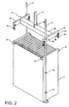
FIG. 2 is a perspective view of the lifting apparatus and the water treatment device in accordance with the present invention. -
FIG. 3A is a plan view of the lifting apparatus,FIG. 3B is a front view thereof, andFIG. 3C is a side view thereof. -
FIGS. 4A through 4D are diagrams explaining a lifting operation of the lifting apparatus in a first operation state. -
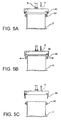
FIG. 5A through 5C are diagrams explaining a lifting operation of the lifting apparatus in a second operation state. -
FIGS. 6A through 6C are diagrams explaining a lifting operation of the lifting apparatus in the first operation state in accordance with another embodiment. -
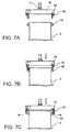
FIGS. 7A through 7C are diagrams explaining a lifting operation of the lifting apparatus in the second operation state in accordance with another embodiment. - Hereinafter, embodiments of the lifting apparatus, the lifting set, and the water treatment facility in accordance with the present invention are explained.
- As shown in
FIGS. 1 and2 , a water treatment facility 1 includes atreatment tank 2 which is a tank body, awater treatment device 3 immersed in water to be treated filled in thetreatment tank 2, and alifting apparatus 4 for lifting thewater treatment device 3. - The
water treatment device 3 is an immersion-typemembrane separation device 3 having a membrane module in which a number of plate-shaped membrane elements are disposed in a casing having upper and lower openings such that respective membrane surfaces are vertically positioned and separated from one another by a predetermined distance provided therebetween, and a diffuser device disposed under the membrane module. Thetreatment tank 2 includes a plurality ofmembrane separation devices 3 immersed therein. - A
lifting apparatus 4 is also provided in order to lift up and transport themembrane separation device 3 in and out of thetreatment tank 2 when a routine maintenance is conducted or a broken membrane element is replaced. It should be noted that, although the present embodiment will be explained in such a case where thewater treatment device 3 is an immersion-typemembrane separation device 3, thewater treatment device 3 to be lifted by thelifting apparatus 4 in accordance with the present invention is not limited to a membrane separation device, and the present invention is applicable to any water treatment device submersed in water, such as a submersible pump. - A pair of
guide bars 8 are provided for each of themembrane separation devices 3 and fixed to the bottom of thetreatment tank 2 so as to stand upright and position themembrane separation device 3 which is immersed therein by engaging with theguide bars 8 by guidedportions 30 thereof provided on respective side walls of themembrane separation device 3. The pair ofguide bars 8 are disposed in the vicinity of a pair of diagonal corners of themembrane separation device 3 in plan view. The guidedportions 30 are provided on upper portion of side walls facing therespective guide bars 8. Each of the guidedportions 30 has a pair of plate-shaped protrusions so as to hold thecorresponding guide bar 8 from both sides. - The
lifting apparatus 4 is hanging from a lifting equipment 6 such as a hoist crane via acable body 5 such as a sling belt or chain so as to be freely raised and lowered. The lifting equipment 6 is supported by a rail 7 provided thereabove so as to be movable along the rail 7 in a horizontal direction. - As shown in
FIGS. 3A, 3B, and 3C , thelifting apparatus 4 includes a frame formed of a pair ofside frames 42 made of steel plates, and acenter frame 43 connecting theside frames 42. Each of theengaging portions 44 is attached vertically to theside frames 42 with a pivot pin P such that an upper portion thereof is rotatable. - Each of the
engaging portions 44 has two elongated plate members lower portions of which are connected via an engaging pin which engages with theengageable portion 32 of thewater treatment device 3, while upper portions of which are rockably attached to theside frame 42 with the pivot pin P. The pivot pin P has a screw portion formed at an end thereof so as to be fastened by a nut. - More specifically, each of the
side frames 42 has a pair ofholes engaging portion 44 can be attached, as shown inFIG. 3C . Theengaging portion 44 is set to the first operation state when it is attached by inserting the pivot pin P into the inner-side hole 48, while it is set to the second operation state when it is attached by inserting the pivot pin P into the outer-side hole 47. In other words, theengaging portion 44 is configured such that the mounting state thereof is changeable between the first operation state and the second operation sate. - In addition, the
center frame 43 has an attachingmember 46 provided at a center portion thereof, to which thecable body 5 coupling to the lifting equipment 6 is attached. Each of the side frames 42 has a guidedportion 40 provided on one side thereof, which engages with a corresponding one of the guide bars 8. The guidedportion 40 also has a pair of plate-shaped protrusions so as to hold theguide bar 8 therebetween. - When the
membrane separation device 3 immersed in thetreatment tank 2 is to be taken out therefrom, the lifting equipment 6 is extended so as to lower and position thelifting apparatus 4 which is set to the first operation state by attaching the engagingportion 44 to the inner-side hole 48 such that the each of the guidedportions 40 engages with the corresponding guide bars 8. - When the
lifting apparatus 4 is lowered, each of the engagingportions 44 of thelifting apparatus 4 becomes in contact with the respectiveengageable portion 32 of themembrane separation device 3 from above as shown inFIG. 4A , and when thelifting apparatus 4 is further lowered, each engagingportion 44 rocks outwardly along aslope portion 32a of the correspondingengageable portion 32 as shown inFIG. 4B . That is, each engagingportion 44 pivots around the pivot pin P thereof. - When the
lifting apparatus 4 further goes downward as shown inFIG. 4C , each of the engagingportions 44 passes the slopedportion 32a of theengageable portion 32 and pivots around the pivot pin P so as to return to its vertical position, whereby the engaging pin of the engagingportion 44 and theengageable portion 32 become engageable with each other. - When the lifting equipment 6 is wound up so as to raise the
lifting apparatus 4 in this engageable state, themembrane separation device 3 is lifted up from thetreatment tank 2 as shown inFIG. 4D . - When the
membrane separation device 3 is to be disposed in thetreatment tank 2 and immersed therein, the engagingportion 44 is first attached to the outer-side whole 47 of thelifting apparatus 4 so as to be set to the second operation state, and then the lifting equipment 6 is wound up so as to raise thelifting apparatus 4 in a state in which the engaging pin of the engagingportion 44 of thelifting apparatus 4 and theengageable portion 32 of themembrane separation device 3 are engaged with each other. - Then, the
lifting apparatus 4 is transported to a predetermined location along the rail 7 and positioned such that the guidedportions 30 of themembrane separation device 3 engage with the corresponding guide bars 8 standing in thetreatment tank 2. The lifting equipment 6 is extended so as to lower thelifting apparatus 4, whereby themembrane separation device 3 is disposed in thetreatment tank 2 and immersed therein. - As shown in
FIG. 5A , as thelifting apparatus 4 goes down from its lifted state, the engaging pin of the engagingportion 44 of thelifting apparatus 4 and theengageable portion 32 of themembrane separation device 3 are gradually disengaged from each other, and when thelifting apparatus 4 is further lowered, the engaging pin of the engagingportion 44 is released from theengageable portion 32 and rocks outwardly, i.e., the engagingportion 44 pivots around the pivot pin P, thereby returning to its vertical position as shown inFIG. 5B . - When the lifting equipment 6 is wound up in this state so as to raise the
lifting apparatus 4 as shown inFIG. 5C , only thelifting apparatus 4 is lifted up. - In other words, when the
membrane separation device 3 is disposed to a predetermined position from the lifted state thereof being lifted by thelifting apparatus 4, and then thelifting apparatus 4 is further brought down and to be closer to themembrane separation device 3, the engagingportion 44 is disengaged from theengageable portion 32 by its weight. - Another embodiment is described below. In the embodiment described above, the first operation state is set when the engaging
portions 44 are attached to the respective side frames 42 by inserting the pivot pin P into the inner-side hole 48, while the second operation state is set when the engagingportions 44 are attached by inserting the pivot pin P into the outer-side hole 47. However, the first operation state can be set when the engaging portions 44are attached by inserting the pivot pin P into the outer-side hole 47, while the second operation state can be set when the engagingportion 44 is attached by inserting the pivot pin P into the inner-side hole 48. - For example, for the first operation state, as shown in
FIG. 6A , the structure of the craw-likeengageable portion 32 described above (seeFIG. 4A ) and that of the engagingportion 44 having the two elongated flat plates separated from each other by the predetermined distance (seeFIG. 4A ) can be switched each other, such that a claw-like engagingportion 44 is used for thelifting apparatus 4, and anengageable portion 32 having two elongated flat plates separated from each other by a predetermined distance is attached to themembrane separation device 3. - As shown in
FIG. 6B , when thelifting apparatus 4 in which the claw-like engagingportion 44 is vertically fixed to the outer-side hole 47 to be set to the first operation state goes down toward themembrane separation device 3 from above, a tip of theengageable portion 32 provided to the side wall of themembrane separation device 3 and aslope portion 44a of the engagingportion 44 become in contact with each other, whereby the engagingportion 44 rocks inwardly. - When the
lifting apparatus 4 further goes down as shown inFIG. 6C , the claw-like engagingportion 44 retunes to its vertical position and engages with theengageable portion 32. When thelifting apparatus 4 is raised in this state, themembrane separation device 3 is lifted up from thetreatment tank 2. - On the other hand, the second operation state is set by vertically attaching the claw-like engaging
portion 44 to the inner-side hole 48 of thelifting apparatus 4, and similarly to the process shown inFIGS. 5A, 5B, and 5C , the engagingportion 44 and theengageable portion 32 of themembrane separation device 3 are engaged with each other beforehand, and then thelifting apparatus 4 is lowered toward thetreatment tank 2 from above so as to install themembrane separation device 3 therein. - When the
lifting apparatus 4 goes further down and gets closer to themembrane separation device 3 after its installation, an inner slope at the tip of the claw portion of the engagingportion 44 slides from theengageable portion 32 provided on the side wall of themembrane separation device 3, whereby the engagingportion 44 rocks around the pivot pin P and returns to its vertical position such that the engagingportion 44 automatically disengages from theengageable portion 32. Thus, thelifting apparatus 4 can be raised in this state. - In the embodiment shown in
FIGS. 5A, 5B, and 5C , the engagingportion 44 set to the second operation state is released from theengageable portion 32 by its weight when thelifting apparatus 4 comes closer to themembrane separation device 3. However, the engagingportion 44 set to the second operation state may be released from theengageable portion 32 by a biased force of an elastic member such as a spring when thelifting apparatus 4 is brought closer to themembrane separation device 3 in another embodiment. -
FIGS. 7A, 7B, and 7C illustrate such an embodiment.FIG. 7A shows the first operation state in which each of the engagingportions 44 are attached to the side frames 42 by inserting the pivot pin P into the inner-side hole 48. In addition, an end of an elastic biasing member, such as acoil spring 50, is attached to the outer-side hole 47, while another end of thecoil spring 50 is detachably attached to an attaching portion of the elongated plate members of the engagingportion 44. When thelifting apparatus 4 is lowered in this state, themembrane separation device 3 becomes ready to be lifted up in a similar manner as that illustrated inFIGS. 4A through 4D . -
FIGS. 7B and 7C illustrate the second operation state. As shown inFIG. 7B , themembrane separation device 3 is lifted up in such a state where thecoil spring 5 is attached to the engagingportion 44 while the engagingportion 44 is engaged with theengageable portion 32 of themembrane separation device 3, and then brought to a predetermined position of thetreatment tank 2, lowered, and installed therein. - As shown in
FIG. 7C , when thelifting apparatus 4 is further lowered to become closer to themembrane separation device 3 in a state in which the engagingportion 44 is biased outwardly around the pivot pin P by the biasing power of thecoil spring 50, the engagingportion 44 is automatically disengaged from theengageable portion 32, and when thelifting apparatus 4 is raised in this state, only thelifting apparatus 4 is lifted up. That is, thecoil spring 50 functions as a biasing means. - As described above, the
lifting apparatus 4 is switchable between the first operation state and the second operation state by changing the attaching position of the engagingportion 44 or by attaching/releasing the biasing means 50. - In such a case where a plurality of
membrane separation devices 3, for example, twomembrane separation devices 3 are stacked in a vertical direction in thetreatment tank 2, they can be lifted up one by one by providing theengageable portions 32 to the frame of each of themembrane separation devices 3. - The lifting set of the present invention includes the above-mentioned
lifting apparatus 4 and themembrane separation device 3 to be lifted, and the water treatment facility of the present invention includes the lifting set and a tank body in which the water treatment device is immersed in water to be treated. - Each embodiment mentioned above is an example of the present invention, and the present invention is not limited by the description. A design of the specific structure of each part can be changed so long as the function and effect of the present invention can be achieved.
-
- 1: water treatment facility
- 2: tank body
- 3: water treatment device
- 4: lifting apparatus
- 30: guiding portion
- 32: engageable portion
- 40: guided portion
- 42, 43: frame members
- 44: engaging portion
Claims (6)
- A lifting apparatus capable of engaging with and disengaging from a water treatment device which is to be lifted, the lifting apparatus comprising:a frame; andan engaging portion pivotably attached to the frame by an upper portion thereof in a vertical position, the engaging portion being capable of engaging with an engageable portion of the water treatment device,wherein the engaging portion has a first operation state in which the engaging portion pivots by contacting the engageable portion as the lifting apparatus approaches the water treatment device from above, and then pivots back to the vertical position as the lifting apparatus further approaches the water treatment device to become closer thereto, whereby the engaging portion and the engageable portion become engageable with each other.
- The lifting apparatus of claim 1, wherein the engaging portion has a second operation state in addition to the first operation state, in which the engaging portion disengages from the engageable portion by a weight thereof or a biased force, when the lifting apparatus further approaches the water treatment device after the water treatment device has been installed into a predetermined position from a lifted state thereof being lifted by the lifting apparatus.
- The lifting apparatus of claim 2, wherein the first operation state and the second operation state are switched by changing a position to which the engaging portion is attached to the frame, or by attaching and releasing a biasing means to the engaging portion.
- A lifting set comprising:the lifting apparatus of any one of claims 1 to 3; andthe water treatment device to be lifted by the lifting apparatus.
- A water treatment facility comprising:the lifting apparatus of any one of claims 1 to 3;the water treatment device to be lifted by the lifting apparatus; anda tank body in which the water treatment device is immersed in liquid to be treated.
- The water treatment facility of claim 5, wherein the water treatment device is a membrane separation device.
Priority Applications (1)
| Application Number | Priority Date | Filing Date | Title |
|---|---|---|---|
| HRP20201057TT HRP20201057T1 (en) | 2013-03-27 | 2014-03-27 | LIFTING DEVICE INTENDED FOR WATER TREATMENT PLANT |
Applications Claiming Priority (2)
| Application Number | Priority Date | Filing Date | Title |
|---|---|---|---|
| JP2013066060A JP6198423B2 (en) | 2013-03-27 | 2013-03-27 | Lifting device, lifting set and water treatment equipment |
| PCT/JP2014/058788 WO2014157487A1 (en) | 2013-03-27 | 2014-03-27 | Lifting apparatus, lifting set, and water treatment facility |
Publications (3)
| Publication Number | Publication Date |
|---|---|
| EP2980026A1 true EP2980026A1 (en) | 2016-02-03 |
| EP2980026A4 EP2980026A4 (en) | 2016-11-30 |
| EP2980026B1 EP2980026B1 (en) | 2020-05-20 |
Family
ID=51624449
Family Applications (1)
| Application Number | Title | Priority Date | Filing Date |
|---|---|---|---|
| EP14774448.6A Active EP2980026B1 (en) | 2013-03-27 | 2014-03-27 | Lifting apparatus for a water treatment facility |
Country Status (6)
| Country | Link |
|---|---|
| US (2) | US20160016762A1 (en) |
| EP (1) | EP2980026B1 (en) |
| JP (1) | JP6198423B2 (en) |
| CN (1) | CN104981432B (en) |
| HR (1) | HRP20201057T1 (en) |
| WO (1) | WO2014157487A1 (en) |
Cited By (2)
| Publication number | Priority date | Publication date | Assignee | Title |
|---|---|---|---|---|
| DE102019204537A1 (en) * | 2019-04-01 | 2020-10-01 | AUDI HUNGARIA Zrt. | Lifting device, system and method for positioning a component |
| EP3075438B1 (en) * | 2013-11-26 | 2021-06-30 | Kubota Corporation | Method for lifting membrane separation apparatus |
Families Citing this family (9)
| Publication number | Priority date | Publication date | Assignee | Title |
|---|---|---|---|---|
| JP6198423B2 (en) | 2013-03-27 | 2017-09-20 | 株式会社クボタ | Lifting device, lifting set and water treatment equipment |
| JP6223399B2 (en) * | 2015-09-18 | 2017-11-01 | 荏原実業株式会社 | Membrane module removal device |
| JP6223400B2 (en) * | 2015-09-18 | 2017-11-01 | 荏原実業株式会社 | Membrane module mounting device |
| JP6222284B1 (en) * | 2016-05-31 | 2017-11-01 | 株式会社明電舎 | Membrane element arrangement structure, membrane cassette and membrane unit |
| JP6222320B1 (en) * | 2016-09-21 | 2017-11-01 | 株式会社明電舎 | Membrane separator |
| SG10201911673PA (en) * | 2016-05-31 | 2020-02-27 | Meidensha Electric Mfg Co Ltd | Film separation device, structure for arranging film element, and film cassette and film unit |
| CN106081875B (en) * | 2016-08-02 | 2017-11-28 | 佛山坚美铝业有限公司 | A kind of automatic hoisting mechanism |
| SE544712C2 (en) * | 2021-02-01 | 2022-10-25 | Veolia Water Solutions & Tech | Filter unit lifting system |
| JP7691095B2 (en) * | 2021-03-15 | 2025-06-11 | メタウォーター株式会社 | Contained Water Treatment System |
Family Cites Families (19)
| Publication number | Priority date | Publication date | Assignee | Title |
|---|---|---|---|---|
| US2335272A (en) * | 1941-07-30 | 1943-11-30 | Paul C Grunwell | Automatic lifting mechanism |
| US3154203A (en) * | 1960-03-25 | 1964-10-27 | Leonard D Barry | Material handling system |
| GB1540847A (en) * | 1976-09-10 | 1979-02-14 | Hartley Simon Ltd | Lifting beam |
| JPS5927925Y2 (en) * | 1979-11-20 | 1984-08-13 | 新日本製鐵株式会社 | Roll lifting device |
| JPS6362505A (en) * | 1986-09-03 | 1988-03-18 | Toshiba Corp | Hollow yarn membrane filter |
| JP2507589B2 (en) * | 1989-04-14 | 1996-06-12 | 株式会社東芝 | Filtration device |
| DK0510328T3 (en) * | 1991-03-07 | 1996-02-05 | Kubota Kk | Apparatus for treating activated sludge |
| US5207468A (en) | 1992-05-27 | 1993-05-04 | Georges Saulnier | Self-adjusting transformer sling |
| JP3387540B2 (en) * | 1993-01-25 | 2003-03-17 | 株式会社クボタ | Membrane separation unit |
| JP2982674B2 (en) * | 1995-12-01 | 1999-11-29 | 日立プラント建設株式会社 | Hanging equipment |
| EP0802145B1 (en) | 1996-04-16 | 2001-01-24 | Topal Industries S.A. | Hoisting yoke |
| JP3461781B2 (en) | 2000-03-08 | 2003-10-27 | 財団法人発電設備技術検査協会 | Method and apparatus for evaluating creep damage of ferromagnetic structure using alternating current magnetization |
| JP2002173288A (en) * | 2000-12-11 | 2002-06-21 | Kobe Steel Ltd | Hoisting accessory for i-bar |
| JP2003266070A (en) * | 2002-03-15 | 2003-09-24 | Nishihara Environment Technology Inc | Membrane filtration apparatus |
| US6830683B2 (en) * | 2002-04-23 | 2004-12-14 | Culligan International Company | Filter cartridge assembly with brine seal and retaining ring |
| US9446970B2 (en) * | 2009-02-24 | 2016-09-20 | Mitsubishi Rayon Co., Ltd. | Membrane module unit and assembly method, disassembly method, and maintenance method for same, and water-treatment apparatus |
| US8388033B2 (en) * | 2009-11-24 | 2013-03-05 | Alltec Lifting Systems Llc | Method and apparatus for hoisting objects using a modular lifting beam |
| JP5606166B2 (en) * | 2010-06-09 | 2014-10-15 | 株式会社クボタ | Water treatment equipment and water treatment equipment lifting equipment |
| JP6198423B2 (en) | 2013-03-27 | 2017-09-20 | 株式会社クボタ | Lifting device, lifting set and water treatment equipment |
-
2013
- 2013-03-27 JP JP2013066060A patent/JP6198423B2/en active Active
-
2014
- 2014-03-27 WO PCT/JP2014/058788 patent/WO2014157487A1/en not_active Ceased
- 2014-03-27 HR HRP20201057TT patent/HRP20201057T1/en unknown
- 2014-03-27 EP EP14774448.6A patent/EP2980026B1/en active Active
- 2014-03-27 CN CN201480004071.7A patent/CN104981432B/en active Active
-
2015
- 2015-09-25 US US14/866,657 patent/US20160016762A1/en not_active Abandoned
-
2018
- 2018-12-20 US US16/228,269 patent/US10549957B2/en active Active
Cited By (3)
| Publication number | Priority date | Publication date | Assignee | Title |
|---|---|---|---|---|
| EP3075438B1 (en) * | 2013-11-26 | 2021-06-30 | Kubota Corporation | Method for lifting membrane separation apparatus |
| DE102019204537A1 (en) * | 2019-04-01 | 2020-10-01 | AUDI HUNGARIA Zrt. | Lifting device, system and method for positioning a component |
| DE102019204537B4 (en) | 2019-04-01 | 2023-02-23 | AUDI HUNGARIA Zrt. | Lifting device, system and method for positioning a component |
Also Published As
| Publication number | Publication date |
|---|---|
| JP2014188441A (en) | 2014-10-06 |
| US20190119077A1 (en) | 2019-04-25 |
| EP2980026B1 (en) | 2020-05-20 |
| CN104981432B (en) | 2018-10-12 |
| EP2980026A4 (en) | 2016-11-30 |
| US10549957B2 (en) | 2020-02-04 |
| HRP20201057T1 (en) | 2020-10-30 |
| JP6198423B2 (en) | 2017-09-20 |
| CN104981432A (en) | 2015-10-14 |
| WO2014157487A1 (en) | 2014-10-02 |
| US20160016762A1 (en) | 2016-01-21 |
Similar Documents
| Publication | Publication Date | Title |
|---|---|---|
| US10549957B2 (en) | Method for operating lifting set including lifting apparatus and water device | |
| EP3179589A1 (en) | Module replacement device of high voltage direct current transmission system | |
| JP2011255305A (en) | Water treatment facility and lifting apparatus of water treatment apparatus | |
| CN217947342U (en) | Mechanical self-detaching hoisting and carrying structure | |
| KR101359406B1 (en) | Overall Heat Transmission Test Piece Cartridge Feeding Apparatus | |
| US11390305B2 (en) | Underfloor device of railway vehicle | |
| CN214987847U (en) | Intelligence rubbish station lift control system | |
| CN217173158U (en) | Material safety elevating platform | |
| CN204559376U (en) | Frequency converter | |
| CN223253218U (en) | Unmanned ship deployment and recovery system | |
| KR101965745B1 (en) | cage connection device for lift | |
| CN215561942U (en) | Simple balance lifting appliance for lifting and welding lower flange plate of steel box girder | |
| CN218618613U (en) | Conveying device and automatic production system | |
| KR102922880B1 (en) | Remote basket controlling apparatus and controlling method thereof | |
| CN214780486U (en) | A lifting mechanism for transporting release agent material barrels | |
| CN204400441U (en) | A kind of building template hanging apparatus | |
| CN213799706U (en) | Safety device for transferring mast lengthening section | |
| CN211035038U (en) | Lifting feeding device for building | |
| KR20130024455A (en) | Jig for welder transport | |
| CN104779776B (en) | Frequency converter | |
| CN208393589U (en) | A kind of locomotive for inside cabin for boat unit | |
| KR101749341B1 (en) | Building walls reinforced fixed mobile District | |
| KR20250128536A (en) | Automatic paper feeder controller using IOT technology | |
| CN112693787A (en) | Intelligence rubbish station lift control system | |
| CN202098969U (en) | Steel plate clamp for handing steel penstock tiles |
Legal Events
| Date | Code | Title | Description |
|---|---|---|---|
| PUAI | Public reference made under article 153(3) epc to a published international application that has entered the european phase |
Free format text: ORIGINAL CODE: 0009012 |
|
| 17P | Request for examination filed |
Effective date: 20150924 |
|
| AK | Designated contracting states |
Kind code of ref document: A1 Designated state(s): AL AT BE BG CH CY CZ DE DK EE ES FI FR GB GR HR HU IE IS IT LI LT LU LV MC MK MT NL NO PL PT RO RS SE SI SK SM TR |
|
| AX | Request for extension of the european patent |
Extension state: BA ME |
|
| DAX | Request for extension of the european patent (deleted) | ||
| REG | Reference to a national code |
Ref country code: DE Ref legal event code: R079 Ref document number: 602014065717 Country of ref document: DE Free format text: PREVIOUS MAIN CLASS: C02F0001000000 Ipc: B01D0065000000 |
|
| A4 | Supplementary search report drawn up and despatched |
Effective date: 20161028 |
|
| RIC1 | Information provided on ipc code assigned before grant |
Ipc: C02F 1/44 20060101ALI20161024BHEP Ipc: B66C 1/10 20060101ALI20161024BHEP Ipc: B01D 61/20 20060101ALI20161024BHEP Ipc: B01D 65/00 20060101AFI20161024BHEP |
|
| STAA | Information on the status of an ep patent application or granted ep patent |
Free format text: STATUS: EXAMINATION IS IN PROGRESS |
|
| 17Q | First examination report despatched |
Effective date: 20190328 |
|
| GRAP | Despatch of communication of intention to grant a patent |
Free format text: ORIGINAL CODE: EPIDOSNIGR1 |
|
| STAA | Information on the status of an ep patent application or granted ep patent |
Free format text: STATUS: GRANT OF PATENT IS INTENDED |
|
| INTG | Intention to grant announced |
Effective date: 20190828 |
|
| GRAJ | Information related to disapproval of communication of intention to grant by the applicant or resumption of examination proceedings by the epo deleted |
Free format text: ORIGINAL CODE: EPIDOSDIGR1 |
|
| STAA | Information on the status of an ep patent application or granted ep patent |
Free format text: STATUS: EXAMINATION IS IN PROGRESS |
|
| GRAP | Despatch of communication of intention to grant a patent |
Free format text: ORIGINAL CODE: EPIDOSNIGR1 |
|
| STAA | Information on the status of an ep patent application or granted ep patent |
Free format text: STATUS: GRANT OF PATENT IS INTENDED |
|
| INTC | Intention to grant announced (deleted) | ||
| INTG | Intention to grant announced |
Effective date: 20200108 |
|
| GRAS | Grant fee paid |
Free format text: ORIGINAL CODE: EPIDOSNIGR3 |
|
| GRAA | (expected) grant |
Free format text: ORIGINAL CODE: 0009210 |
|
| STAA | Information on the status of an ep patent application or granted ep patent |
Free format text: STATUS: THE PATENT HAS BEEN GRANTED |
|
| AK | Designated contracting states |
Kind code of ref document: B1 Designated state(s): AL AT BE BG CH CY CZ DE DK EE ES FI FR GB GR HR HU IE IS IT LI LT LU LV MC MK MT NL NO PL PT RO RS SE SI SK SM TR |
|
| REG | Reference to a national code |
Ref country code: GB Ref legal event code: FG4D |
|
| REG | Reference to a national code |
Ref country code: CH Ref legal event code: EP |
|
| REG | Reference to a national code |
Ref country code: DE Ref legal event code: R096 Ref document number: 602014065717 Country of ref document: DE |
|
| REG | Reference to a national code |
Ref country code: AT Ref legal event code: REF Ref document number: 1272242 Country of ref document: AT Kind code of ref document: T Effective date: 20200615 |
|
| REG | Reference to a national code |
Ref country code: HR Ref legal event code: TUEP Ref document number: P20201057T Country of ref document: HR |
|
| REG | Reference to a national code |
Ref country code: LT Ref legal event code: MG4D |
|
| REG | Reference to a national code |
Ref country code: NL Ref legal event code: MP Effective date: 20200520 |
|
| PG25 | Lapsed in a contracting state [announced via postgrant information from national office to epo] |
Ref country code: FI Free format text: LAPSE BECAUSE OF FAILURE TO SUBMIT A TRANSLATION OF THE DESCRIPTION OR TO PAY THE FEE WITHIN THE PRESCRIBED TIME-LIMIT Effective date: 20200520 Ref country code: LT Free format text: LAPSE BECAUSE OF FAILURE TO SUBMIT A TRANSLATION OF THE DESCRIPTION OR TO PAY THE FEE WITHIN THE PRESCRIBED TIME-LIMIT Effective date: 20200520 Ref country code: SE Free format text: LAPSE BECAUSE OF FAILURE TO SUBMIT A TRANSLATION OF THE DESCRIPTION OR TO PAY THE FEE WITHIN THE PRESCRIBED TIME-LIMIT Effective date: 20200520 Ref country code: IS Free format text: LAPSE BECAUSE OF FAILURE TO SUBMIT A TRANSLATION OF THE DESCRIPTION OR TO PAY THE FEE WITHIN THE PRESCRIBED TIME-LIMIT Effective date: 20200920 Ref country code: NO Free format text: LAPSE BECAUSE OF FAILURE TO SUBMIT A TRANSLATION OF THE DESCRIPTION OR TO PAY THE FEE WITHIN THE PRESCRIBED TIME-LIMIT Effective date: 20200820 Ref country code: GR Free format text: LAPSE BECAUSE OF FAILURE TO SUBMIT A TRANSLATION OF THE DESCRIPTION OR TO PAY THE FEE WITHIN THE PRESCRIBED TIME-LIMIT Effective date: 20200821 Ref country code: PT Free format text: LAPSE BECAUSE OF FAILURE TO SUBMIT A TRANSLATION OF THE DESCRIPTION OR TO PAY THE FEE WITHIN THE PRESCRIBED TIME-LIMIT Effective date: 20200921 |
|
| REG | Reference to a national code |
Ref country code: HR Ref legal event code: T1PR Ref document number: P20201057 Country of ref document: HR |
|
| PG25 | Lapsed in a contracting state [announced via postgrant information from national office to epo] |
Ref country code: RS Free format text: LAPSE BECAUSE OF FAILURE TO SUBMIT A TRANSLATION OF THE DESCRIPTION OR TO PAY THE FEE WITHIN THE PRESCRIBED TIME-LIMIT Effective date: 20200520 Ref country code: LV Free format text: LAPSE BECAUSE OF FAILURE TO SUBMIT A TRANSLATION OF THE DESCRIPTION OR TO PAY THE FEE WITHIN THE PRESCRIBED TIME-LIMIT Effective date: 20200520 Ref country code: BG Free format text: LAPSE BECAUSE OF FAILURE TO SUBMIT A TRANSLATION OF THE DESCRIPTION OR TO PAY THE FEE WITHIN THE PRESCRIBED TIME-LIMIT Effective date: 20200820 |
|
| REG | Reference to a national code |
Ref country code: AT Ref legal event code: MK05 Ref document number: 1272242 Country of ref document: AT Kind code of ref document: T Effective date: 20200520 |
|
| PG25 | Lapsed in a contracting state [announced via postgrant information from national office to epo] |
Ref country code: NL Free format text: LAPSE BECAUSE OF FAILURE TO SUBMIT A TRANSLATION OF THE DESCRIPTION OR TO PAY THE FEE WITHIN THE PRESCRIBED TIME-LIMIT Effective date: 20200520 Ref country code: AL Free format text: LAPSE BECAUSE OF FAILURE TO SUBMIT A TRANSLATION OF THE DESCRIPTION OR TO PAY THE FEE WITHIN THE PRESCRIBED TIME-LIMIT Effective date: 20200520 |
|
| PG25 | Lapsed in a contracting state [announced via postgrant information from national office to epo] |
Ref country code: CZ Free format text: LAPSE BECAUSE OF FAILURE TO SUBMIT A TRANSLATION OF THE DESCRIPTION OR TO PAY THE FEE WITHIN THE PRESCRIBED TIME-LIMIT Effective date: 20200520 Ref country code: SM Free format text: LAPSE BECAUSE OF FAILURE TO SUBMIT A TRANSLATION OF THE DESCRIPTION OR TO PAY THE FEE WITHIN THE PRESCRIBED TIME-LIMIT Effective date: 20200520 Ref country code: EE Free format text: LAPSE BECAUSE OF FAILURE TO SUBMIT A TRANSLATION OF THE DESCRIPTION OR TO PAY THE FEE WITHIN THE PRESCRIBED TIME-LIMIT Effective date: 20200520 Ref country code: DK Free format text: LAPSE BECAUSE OF FAILURE TO SUBMIT A TRANSLATION OF THE DESCRIPTION OR TO PAY THE FEE WITHIN THE PRESCRIBED TIME-LIMIT Effective date: 20200520 Ref country code: ES Free format text: LAPSE BECAUSE OF FAILURE TO SUBMIT A TRANSLATION OF THE DESCRIPTION OR TO PAY THE FEE WITHIN THE PRESCRIBED TIME-LIMIT Effective date: 20200520 Ref country code: AT Free format text: LAPSE BECAUSE OF FAILURE TO SUBMIT A TRANSLATION OF THE DESCRIPTION OR TO PAY THE FEE WITHIN THE PRESCRIBED TIME-LIMIT Effective date: 20200520 Ref country code: RO Free format text: LAPSE BECAUSE OF FAILURE TO SUBMIT A TRANSLATION OF THE DESCRIPTION OR TO PAY THE FEE WITHIN THE PRESCRIBED TIME-LIMIT Effective date: 20200520 |
|
| REG | Reference to a national code |
Ref country code: DE Ref legal event code: R097 Ref document number: 602014065717 Country of ref document: DE |
|
| PG25 | Lapsed in a contracting state [announced via postgrant information from national office to epo] |
Ref country code: PL Free format text: LAPSE BECAUSE OF FAILURE TO SUBMIT A TRANSLATION OF THE DESCRIPTION OR TO PAY THE FEE WITHIN THE PRESCRIBED TIME-LIMIT Effective date: 20200520 Ref country code: SK Free format text: LAPSE BECAUSE OF FAILURE TO SUBMIT A TRANSLATION OF THE DESCRIPTION OR TO PAY THE FEE WITHIN THE PRESCRIBED TIME-LIMIT Effective date: 20200520 |
|
| PLBE | No opposition filed within time limit |
Free format text: ORIGINAL CODE: 0009261 |
|
| STAA | Information on the status of an ep patent application or granted ep patent |
Free format text: STATUS: NO OPPOSITION FILED WITHIN TIME LIMIT |
|
| REG | Reference to a national code |
Ref country code: HR Ref legal event code: ODRP Ref document number: P20201057 Country of ref document: HR Payment date: 20210324 Year of fee payment: 8 |
|
| 26N | No opposition filed |
Effective date: 20210223 |
|
| PG25 | Lapsed in a contracting state [announced via postgrant information from national office to epo] |
Ref country code: SI Free format text: LAPSE BECAUSE OF FAILURE TO SUBMIT A TRANSLATION OF THE DESCRIPTION OR TO PAY THE FEE WITHIN THE PRESCRIBED TIME-LIMIT Effective date: 20200520 |
|
| REG | Reference to a national code |
Ref country code: DE Ref legal event code: R119 Ref document number: 602014065717 Country of ref document: DE |
|
| PG25 | Lapsed in a contracting state [announced via postgrant information from national office to epo] |
Ref country code: MC Free format text: LAPSE BECAUSE OF FAILURE TO SUBMIT A TRANSLATION OF THE DESCRIPTION OR TO PAY THE FEE WITHIN THE PRESCRIBED TIME-LIMIT Effective date: 20200520 |
|
| REG | Reference to a national code |
Ref country code: CH Ref legal event code: PL |
|
| GBPC | Gb: european patent ceased through non-payment of renewal fee |
Effective date: 20210327 |
|
| REG | Reference to a national code |
Ref country code: BE Ref legal event code: MM Effective date: 20210331 |
|
| PG25 | Lapsed in a contracting state [announced via postgrant information from national office to epo] |
Ref country code: CH Free format text: LAPSE BECAUSE OF NON-PAYMENT OF DUE FEES Effective date: 20210331 Ref country code: LI Free format text: LAPSE BECAUSE OF NON-PAYMENT OF DUE FEES Effective date: 20210331 Ref country code: LU Free format text: LAPSE BECAUSE OF NON-PAYMENT OF DUE FEES Effective date: 20210327 Ref country code: DE Free format text: LAPSE BECAUSE OF NON-PAYMENT OF DUE FEES Effective date: 20211001 Ref country code: IE Free format text: LAPSE BECAUSE OF NON-PAYMENT OF DUE FEES Effective date: 20210327 Ref country code: GB Free format text: LAPSE BECAUSE OF NON-PAYMENT OF DUE FEES Effective date: 20210327 |
|
| REG | Reference to a national code |
Ref country code: HR Ref legal event code: ODRP Ref document number: P20201057 Country of ref document: HR Payment date: 20220325 Year of fee payment: 9 |
|
| PG25 | Lapsed in a contracting state [announced via postgrant information from national office to epo] |
Ref country code: BE Free format text: LAPSE BECAUSE OF NON-PAYMENT OF DUE FEES Effective date: 20210331 |
|
| REG | Reference to a national code |
Ref country code: HR Ref legal event code: ODRP Ref document number: P20201057 Country of ref document: HR Payment date: 20230215 Year of fee payment: 10 |
|
| PG25 | Lapsed in a contracting state [announced via postgrant information from national office to epo] |
Ref country code: HU Free format text: LAPSE BECAUSE OF FAILURE TO SUBMIT A TRANSLATION OF THE DESCRIPTION OR TO PAY THE FEE WITHIN THE PRESCRIBED TIME-LIMIT; INVALID AB INITIO Effective date: 20140327 |
|
| PG25 | Lapsed in a contracting state [announced via postgrant information from national office to epo] |
Ref country code: CY Free format text: LAPSE BECAUSE OF FAILURE TO SUBMIT A TRANSLATION OF THE DESCRIPTION OR TO PAY THE FEE WITHIN THE PRESCRIBED TIME-LIMIT Effective date: 20200520 |
|
| REG | Reference to a national code |
Ref country code: HR Ref legal event code: ODRP Ref document number: P20201057 Country of ref document: HR Payment date: 20240208 Year of fee payment: 11 |
|
| PG25 | Lapsed in a contracting state [announced via postgrant information from national office to epo] |
Ref country code: MK Free format text: LAPSE BECAUSE OF FAILURE TO SUBMIT A TRANSLATION OF THE DESCRIPTION OR TO PAY THE FEE WITHIN THE PRESCRIBED TIME-LIMIT Effective date: 20200520 |
|
| PG25 | Lapsed in a contracting state [announced via postgrant information from national office to epo] |
Ref country code: MT Free format text: LAPSE BECAUSE OF FAILURE TO SUBMIT A TRANSLATION OF THE DESCRIPTION OR TO PAY THE FEE WITHIN THE PRESCRIBED TIME-LIMIT Effective date: 20200520 |
|
| REG | Reference to a national code |
Ref country code: HR Ref legal event code: ODRP Ref document number: P20201057 Country of ref document: HR Payment date: 20250207 Year of fee payment: 12 |
|
| REG | Reference to a national code |
Ref country code: HR Ref legal event code: ODRP Ref document number: P20201057 Country of ref document: HR Payment date: 20260205 Year of fee payment: 13 |
|
| PGFP | Annual fee paid to national office [announced via postgrant information from national office to epo] |
Ref country code: HR Payment date: 20260205 Year of fee payment: 13 |
|
| PGFP | Annual fee paid to national office [announced via postgrant information from national office to epo] |
Ref country code: IT Payment date: 20260220 Year of fee payment: 13 |
|
| PGFP | Annual fee paid to national office [announced via postgrant information from national office to epo] |
Ref country code: FR Payment date: 20260209 Year of fee payment: 13 |
|
| PGFP | Annual fee paid to national office [announced via postgrant information from national office to epo] |
Ref country code: TR Payment date: 20260326 Year of fee payment: 13 |