EP2979879A1 - Printer - Google Patents
Printer Download PDFInfo
- Publication number
- EP2979879A1 EP2979879A1 EP13880607.0A EP13880607A EP2979879A1 EP 2979879 A1 EP2979879 A1 EP 2979879A1 EP 13880607 A EP13880607 A EP 13880607A EP 2979879 A1 EP2979879 A1 EP 2979879A1
- Authority
- EP
- European Patent Office
- Prior art keywords
- platen roller
- opening
- printer
- roll
- holding mechanism
- Prior art date
- Legal status (The legal status is an assumption and is not a legal conclusion. Google has not performed a legal analysis and makes no representation as to the accuracy of the status listed.)
- Granted
Links
Images


Classifications
-
- B—PERFORMING OPERATIONS; TRANSPORTING
- B41—PRINTING; LINING MACHINES; TYPEWRITERS; STAMPS
- B41J—TYPEWRITERS; SELECTIVE PRINTING MECHANISMS, i.e. MECHANISMS PRINTING OTHERWISE THAN FROM A FORME; CORRECTION OF TYPOGRAPHICAL ERRORS
- B41J11/00—Devices or arrangements of selective printing mechanisms, e.g. ink-jet printers or thermal printers, for supporting or handling copy material in sheet or web form
- B41J11/02—Platens
- B41J11/04—Roller platens
-
- B—PERFORMING OPERATIONS; TRANSPORTING
- B41—PRINTING; LINING MACHINES; TYPEWRITERS; STAMPS
- B41J—TYPEWRITERS; SELECTIVE PRINTING MECHANISMS, i.e. MECHANISMS PRINTING OTHERWISE THAN FROM A FORME; CORRECTION OF TYPOGRAPHICAL ERRORS
- B41J11/00—Devices or arrangements of selective printing mechanisms, e.g. ink-jet printers or thermal printers, for supporting or handling copy material in sheet or web form
-
- B—PERFORMING OPERATIONS; TRANSPORTING
- B41—PRINTING; LINING MACHINES; TYPEWRITERS; STAMPS
- B41J—TYPEWRITERS; SELECTIVE PRINTING MECHANISMS, i.e. MECHANISMS PRINTING OTHERWISE THAN FROM A FORME; CORRECTION OF TYPOGRAPHICAL ERRORS
- B41J11/00—Devices or arrangements of selective printing mechanisms, e.g. ink-jet printers or thermal printers, for supporting or handling copy material in sheet or web form
- B41J11/0095—Detecting means for copy material, e.g. for detecting or sensing presence of copy material or its leading or trailing end
-
- B—PERFORMING OPERATIONS; TRANSPORTING
- B41—PRINTING; LINING MACHINES; TYPEWRITERS; STAMPS
- B41J—TYPEWRITERS; SELECTIVE PRINTING MECHANISMS, i.e. MECHANISMS PRINTING OTHERWISE THAN FROM A FORME; CORRECTION OF TYPOGRAPHICAL ERRORS
- B41J15/00—Devices or arrangements of selective printing mechanisms, e.g. ink-jet printers or thermal printers, specially adapted for supporting or handling copy material in continuous form, e.g. webs
- B41J15/04—Supporting, feeding, or guiding devices; Mountings for web rolls or spindles
- B41J15/042—Supporting, feeding, or guiding devices; Mountings for web rolls or spindles for loading rolled-up continuous copy material into printers, e.g. for replacing a used-up paper roll; Point-of-sale printers with openable casings allowing access to the rolled-up continuous copy material
-
- B—PERFORMING OPERATIONS; TRANSPORTING
- B41—PRINTING; LINING MACHINES; TYPEWRITERS; STAMPS
- B41J—TYPEWRITERS; SELECTIVE PRINTING MECHANISMS, i.e. MECHANISMS PRINTING OTHERWISE THAN FROM A FORME; CORRECTION OF TYPOGRAPHICAL ERRORS
- B41J2/00—Typewriters or selective printing mechanisms characterised by the printing or marking process for which they are designed
- B41J2/315—Typewriters or selective printing mechanisms characterised by the printing or marking process for which they are designed characterised by selective application of heat to a heat sensitive printing or impression-transfer material
- B41J2/32—Typewriters or selective printing mechanisms characterised by the printing or marking process for which they are designed characterised by selective application of heat to a heat sensitive printing or impression-transfer material using thermal heads
-
- B—PERFORMING OPERATIONS; TRANSPORTING
- B41—PRINTING; LINING MACHINES; TYPEWRITERS; STAMPS
- B41J—TYPEWRITERS; SELECTIVE PRINTING MECHANISMS, i.e. MECHANISMS PRINTING OTHERWISE THAN FROM A FORME; CORRECTION OF TYPOGRAPHICAL ERRORS
- B41J29/00—Details of, or accessories for, typewriters or selective printing mechanisms not otherwise provided for
- B41J29/02—Framework
- B41J29/023—Framework with reduced dimensions
-
- B—PERFORMING OPERATIONS; TRANSPORTING
- B41—PRINTING; LINING MACHINES; TYPEWRITERS; STAMPS
- B41J—TYPEWRITERS; SELECTIVE PRINTING MECHANISMS, i.e. MECHANISMS PRINTING OTHERWISE THAN FROM A FORME; CORRECTION OF TYPOGRAPHICAL ERRORS
- B41J29/00—Details of, or accessories for, typewriters or selective printing mechanisms not otherwise provided for
- B41J29/12—Guards, shields or dust excluders
- B41J29/13—Cases or covers
-
- B—PERFORMING OPERATIONS; TRANSPORTING
- B41—PRINTING; LINING MACHINES; TYPEWRITERS; STAMPS
- B41J—TYPEWRITERS; SELECTIVE PRINTING MECHANISMS, i.e. MECHANISMS PRINTING OTHERWISE THAN FROM A FORME; CORRECTION OF TYPOGRAPHICAL ERRORS
- B41J3/00—Typewriters or selective printing or marking mechanisms characterised by the purpose for which they are constructed
- B41J3/36—Typewriters or selective printing or marking mechanisms characterised by the purpose for which they are constructed for portability, i.e. hand-held printers or laptop printers
-
- B—PERFORMING OPERATIONS; TRANSPORTING
- B41—PRINTING; LINING MACHINES; TYPEWRITERS; STAMPS
- B41J—TYPEWRITERS; SELECTIVE PRINTING MECHANISMS, i.e. MECHANISMS PRINTING OTHERWISE THAN FROM A FORME; CORRECTION OF TYPOGRAPHICAL ERRORS
- B41J2202/00—Embodiments of or processes related to ink-jet or thermal heads
- B41J2202/30—Embodiments of or processes related to thermal heads
- B41J2202/31—Thermal printer with head or platen movable
Definitions
- a present disclosure relates to a printer.
- the present disclosure relates to a miniaturized printer with a simplified structure.
- a thermal-type printer that prints via thermal transfer onto a printing medium, by pressing and clamping a printing medium with a thermal head and a platen roller, and selectively heating a heating element that is above the thermal head.
- the platen roller of the printer requires periodic exchange because problems occur such as roller wear from feeding of the printing medium, deterioration of a roller element resulting from an environmental factor or passage of time, or the like.
- a user or serviceman desires a method of performing an easier and faster exchange each time.
- the printer is a portable printer
- greater miniaturization is desirable for greater portability when compared to a conventional printer.
- JP-A 2001-302073 describes unitization of a platen and a fixed blade, such that part detachment and part attachment may be performed via a single process, and a maintenance process may be easily performed.
- Patent Literature 1 JP-A 2001-302073
- a present disclosure has been conceived of in view of various conventional problems. Accordingly, a printer is proposed that allows an exchange and attachment of a platen roller via a simple configuration and method, and allows for printer miniaturization.
- the present invention includes:
- the detector may be supported on a platen roller holder.
- the first roll supporter may be formed from a plurality of ribs.
- the platen roller holding mechanism may include a guide that guides the sheet member in a vicinity of an upstream side of the platen roller.
- the opening and closing cover may include a holding hole that rotatably supports the platen roller and an insertion hole that detachably inserts a shaft of the platen roller into the support hole, and the platen roller holding mechanism may include a platen roller holder that engages with the opening and closing cover by fitting into the insertion hole.
- the holding hole that engages with the platen roller holder may be a long hole, and the platen roller may freely move inside the long hole.
- a second roll supporter may be formed on an inner surface of the opening and closing cover, and the first roll supporter of the platen roller holding mechanism and the second roll supporter may be aligned to form a single arc.
- printer miniaturization and platen roller exchange are made possible via a simple configuration and method.
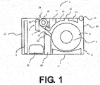
- FIG. 1 shows a schematic side surface view of a thermal printer 1 according to Embodiment I of a present disclosure, and an opening and closing cover 12 in an opened configuration with respect to a printer housing 10.
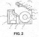
- FIG. 2 shows the opening and closing cover 12 in an opened configuration with respect to the printer housing 10.
- the thermal printer 1 is a portable printer having an internal battery.
- the thermal printer 1 includes: a printer body 2; a supplying part 3; a detector 4; a printer 5; and a controller 6.
- the printing medium used in Embodiment 1 is a continuous label body L that has a plurality of labels temporarily attached at predetermined intervals on a strip-shaped mount.
- the printing medium is used by being rolled into rolled-shape.
- the printer body 2 includes: a printer housing 10; a printer opening and closing shaft 11; an opening and closing cover 12; and a label ejection port 13.
- the printer housing 10 includes a bottom plate and a side plate. The printer housing 10 is such that the printer opening and closing shaft 11 is attached to a first end of the side plate. The opening and closing cover 12 may be rotated to attach to the printer opening and closing shaft 11.
- a closed configuration of the printer housing 10 is shown in FIG. 1 and an opened configuration of the printer housing 10 is shown in FIG. 2 .
- a space is formed between a second end of the opening and closing cover 12 and the printer housing 10 as the label ejection port 13.
- the continuous label body L which the printer 5 has applied print to, is fed from a feeding direction upstream side where supplying part 3 is disposed towards a feeding direction downstream side where the label ejection port 13 is disposed.
- the continuous label body L is ejected to an exterior of the printer body 2.
- the first roll support plate 14 is a thin plate that has one side surface cut into an arc shape.
- a plurality of first roll support plates 14 are disposed at predetermined intervals.
- the plurality of first roll support plates 14 have an arc-shaped surface that faces the side of the roll-shaped continuous label body L.
- the plurality of first roll support plates 14 are disposed in the printer housing 10 in parallel with a winding direction of the continuous label body L.
- a second roll supporter 15 and a third roll supporter 16 are thin plates that each have one side surface cut to form a single arc-shaped fourth roll supporter 39 of a platen roller holding mechanism 17 mentioned hereinafter.
- the second roll supporter 15 and the third roll supporter 16 are disposed on an inner surface of the opening and closing cover 12.
- the plurality of second roll supporters 15 are disposed at predetermined intervals in a label width direction, on a first side of the opening and closing cover 12 (feeding direction upstream side).
- the plurality of second roll supporters 15 have an arc-shaped surface that faces the side of the continuous label body L in a case where the opening and closing cover 12 is in an opened configuration.
- the plurality of second roll supporters 15 are attached in parallel with a winding direction of the continuous label body L.
- the plurality of third roll supporters 16 and the plurality of second roll supporters 15 are each aligned into a plurality of rows.
- the plurality of third roll supporters 16 are attached to another side (namely, feeding direction downstream side) of the opening and closing cover 12, such that the second roll supporter 15, the third roll supporter 16, and the fourth roll supporter 39 of a platen roller holding mechanism 17 form a single arc.
- the continuous label body L may be smoothly fed without rotation by using the roll supporters to reduce a contact surface area of a roll-shaped continuous label body L inside the supplying part 3.
- the label detector 4 includes a light emitter 20 and a light receiver 21 as the detector.
- the light receiver 21 is attached to a first label guide 18 disposed on the printer housing 10.
- the first label guide 18 is part of a feeding pathway that guides a surface side (printing surface side) of the continuous label body L and prevents flapping of the continuous label body L.
- the light emitter 20 attached to the platen roller holding mechanism 17 is disposed on a second end side of the opening and closing cover 12.
- the platen roller holding mechanism 17 is a member that may be composed of a material such as a resin.
- the platen roller holding mechanism 17 is disposed between the third roll supporter 16 and a platen roller 23 (vicinity of an upstream side of the printer 5 ).
- the first label guide 18 is also a member composed of a material such as a resin.
- the first label guide 18 is attached to the printer housing 10.
- the first label guide 18 is disposed between the first roll supporter 14 and a battery 25.
- the platen roller holding mechanism 17 and the first label guide 18 are disposed so as to face each other, and a part of the platen roller holding mechanism 17 that faces the first label guide 18 forms a second label guide 37 that guides a rear surface side (mount side) of continuous label body L.
- the surfaces of the platen roller holding mechanism 17 and the first label guide 18 that oppose each other form mutually inclined parallel surfaces that face the printer 5, and a label feeding pathway 19 of the continuous label body L is formed by the first label guide 18 and the second label guide 37.
- the light emitter 20 is attached to the platen roller holding mechanism 17 so as to emit light from a rear surface side of the continuous label body L above the label feeding pathway 19.
- the light receiver 21 is attached to the first label guide 18 on a surface side of the continuous label body L above the label feeding pathway 19, such that a light transmission emitted from the light emitter 20 facing the continuous label body L is received.
- a reflection-type sensor receives a reflected amount of emitted light may be disposed in the platen roller holding mechanism 17.
- a first light emitter or a light receiver of a transmission-type sensor or a reflection-type sensor may be included in the platen roller holding mechanism 17, while a second light emitter or light receiver of a transmission-type sensor may be included the first label guide 18.
- the label printer 5 includes a thermal head 22 and the platen roller 23.
- the thermal head 22 is disposed on the printer housing 10 in a vicinity of the label ejection port 13.
- the platen roller 23 is rotatably attached to the platen roller holding mechanism 17 of the opening and closing cover 12.
- the heating element of the surface side of the thermal head 22 and the platen roller 23 are both disposed so as to face each other in a case where the opening and closing cover 12 is in a closed configuration.
- a drive motor (not shown) is included in the printer housing 10. The drive motor may be rotatably driven by engaging the gears of the platen roller 23 while the opening and closing cover 12 is in a closed configuration.
- the thermal head 22 includes a head bracket (not shown).
- the head bracket is configured to rotatably support a bearing 35 of the platen roller 34 by a platen engagement part disposed on both side surfaces of the head bracket in a case where the opening and closing cover 12 is in a closed configuration.
- An elastic member (not shown) is disposed on the head bracket.
- the thermal head 22 is pressed on a side of the platen roller 23 via a predetermined pressing force in a case where the continuous label body L is sandwiched by the platen roller 23 and the thermal head 22.
- printing is applied to the continuous label body L, and the continuous label body L is fed to the label ejection port 13.
- the elastic member maintains a closed configuration by biasing the bearing 35 of the platen roller 34 in support direction via the platen engagement part.
- the opening and closing cover 12 may be disengaged by rotating the head bracket against the biasing force of the elastic member and disengaging the bearing 35 from the platen engagement part.
- the printer 6 includes a control board 24 and the battery 25.
- the control board 24 includes: a CPU; a ROM: and a RAM, or the like.
- the control board 24 controls an operation of each part.
- the battery 25 supplies power for the operation of each part.
- the thermal printer 1 of the present embodiment 1 includes the abovementioned configuration.
- the continuous label body L is fed to a label supplying part 3.
- the fed continuous label body L is fed to the label printer 5 via the label detector 4.
- the continuous label body L in the label printer 5 is sandwiched between the thermal head 22 and the platen roller 23, and printing is applied at a predetermined location. After the printing has been applied, the continuous label body L is ejected from the label ejection port 13 to the exterior.
- FIG. 3 shows a perspective view of a rear side of the opening and closing cover 12.
- the above described second roll supporter 15, the third roll supporter 16, a screw hole 30, a platen roll holding protrusion piece 31, and a space 32 are disposed in an inner side surface of the opening and closing cover 12.
- a cover opening and closing shaft through hole 12A and a cover opening and closing shaft through hole 15A are disposed on a first end of the opening and closing cover 12.
- a cover opening and closing shaft 11 is a metallic cylindrical shaft. The cover opening and closing shaft 11 is inserted into the cover opening and closing shaft through hole 12A and the cover opening and closing shaft through hole 15A.
- a first and second threaded hole 30 are disposed on a downstream side of a plurality of third roll supporters 16.
- a screw (not shown) is threaded into the first and second threaded hole 30 so as to attach and fix the platen roller holding mechanism 17 to the opening and closing cover 12.
- the second roll supporter 15, the third roll supporter 16, the first roll supporter 14 of the printer housing 10, and the hereinafter-mentioned fourth roll supporter 39 of the platen roller holding mechanism 17 function as roll guides that guide a peripheral surface of the roll-shaped continuous label body L loaded onto the label supplying part 3.
- the platen roller holding protrusion piece 31 is disposed on both side surfaces of an end opposite to a side that includes the cover opening and closing shaft 11 and the cover opening and closing shaft through hole 12A.
- the space 32 is formed between the platen roller holding protrusion piece 31 and the opening and closing cover 12.
- the space 32 includes a platen roller insertion hole 32A and a platen roller holding hole 32B.
- the platen roller insertion hole 32A allows a platen roller holder 38 of the hereinafter described platen roller holding mechanism 17 to fit into the space 32; and the platen roller holding hole 32B allows a shaft of the platen roller 23 to pass into the space 32.
- the platen roller holding hole 32B is formed as a long hole.
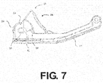
- the platen roller holder 38 is inserted into the platen roller insertion hole 32A as shown in FIG. 7 .
- the long hole is longer than the diameter of the platen roller shaft 33.
- the platen roller shaft 33 is freely rotatably within the long hole and freely movable in a feeding direction of the continuous label body L.
- relative positioning of the thermal head 22 and the platen roller 23 may be achieved by the platen engagement part of the head bracket.
- optimum positioning of the thermal head 22 and the platen roller 23 may be achieved without the influence of an assembly error, in order to enable an adjustment of a position of the platen roller 34 within the long hole even in a case of a device assembly error.
- FIG. 4 shows a perspective view of the platen roller 23.
- the platen roller 23 includes: a platen roller shaft 33; a platen roller body 34; and a bearing 35.
- the platen roller shaft 33 is composed of a metal such as stainless steel.
- the platen roller shaft 33 has a first end of a cylindrical metal rod cut into a cross-sectional D shape.
- a gear (not shown) of the platen roller 34 is fixed to the first end.
- the platen roller body 34 is an elastic body, e.g., a polyurethane rubber or a silicone rubber.
- the platen roller body 34 has a hole at a central axis thereof. The platen roller shaft 33 is inserted and fixed to the hole.
- the platen roller body 34 is also rotatably driven.
- a first and second bearing 35 are fixed at intervals to both sides of the platen roller shaft 33, and fixed at intervals to an exterior of the platen roller body 34.
- FIG. 5 shows a perspective view of the platen roller holding mechanism 17.
- the platen roller holding mechanism 17 is a member that has a width approximately equal to a width direction of the printer housing 10.
- the platen roller holding mechanism 17 includes: a label roll supporter 36; the second label guide 37; and the platen roller holder 38.
- the label roll supporter 36 is a cross-sectional arc-shaped surface disposed on one surface of the platen roller holding mechanism 17.
- the label roll supporter 36 includes the fourth roller supporter 39.
- the plurality of fourth roll supporters 39 are plate-shaped members that are vertically erected on a surface of the label supporter 36. A vicinity of an upper portion thereof is arc-shaped so as to rotatably support a roll-shaped continuous label body L inside the supplying part 3 .
- two screw through holes 40 are disposed on the platen roller holding mechanism 17.
- the platen roller holding mechanism 17 is attached to the opening and closing cover 12 by a screw (not shown).
- the second label guide 37 is a surface disposed on the opposite surface of the label roll supporter 36.
- the second label guide 37 forms a part of the feeding pathway along with the first label guide 18.
- a detector window 41 is disposed on the second label guide.
- the second label guide 37 and the label roll supporter 36 are both integrally formed via a curved part 17A that is bent into an acute angle. The acute angle allows for the label supplying part to have a larger arc, the paper roll to be further stabilized, the continuous label body L to be guided, and the label feeding pathway to be narrowed by an interval between the first label guide 18 and the second label guide 37, such that the continuous label body L may be more accurately fed to the printer.
- the detector includes the issuing device 20 positioned on the detector window 41. The light emitter 20 is part of the detector. Because the flapping of the continuous label body L may be prevented within a narrow feeding pathway, a single detection of a label may be performed in highly precise manner.
- the first and second platen roller holder 38 is disposed between the label roll supporter 36 and the second label guide 37 and on a lower part of the second label guide 37, on both ends of the platen roller holding mechanism 17.
- the first and second platen roller holder 38 is integrally formed with the platen roller holding mechanism 17.
- the first and second platen roller holder 38 is a protruding piece that outwardly protrudes in a curved shape. The protruding piece is formed so as to engage with the platen roller insertion hole 32A of the printer body 2.
- FIG. 6 shows a perspective view of the cover opening and closing shaft 11, the platen roller 23, and the platen roller holding mechanism 17 attached to the opening and closing cover 12.
- the periphery of the opening and closing cover 12 has the above configuration.
- the cover opening and closing shaft 11 inserts into the cover opening and closing shaft through hole 12A, 15A, included at a first end.
- the opening and closing cover 12 freely rotates with respect to the printer housing 10.
- the opening and closing cover 12 is configured to open and close with respect to the printer housing 10.
- the platen roller shaft 33 that is between the bearing 35 and the platen roller body 34 of the platen roller 23 on an end at an opposite side passes through a platen roller holding hole 32B, and fits into a platen roller insertion hole 32A by having the platen roller holder 38 of the platen roller holding mechanism 17 engage with the platen roller insertion hole 32A, such that the platen roller 23 is rotatably supported inside the platen roller holding hole 32B.
- the label roll supporter 36 of the platen roller holding mechanism 17 rotatably supports a roll-shaped continuous label body L.
- the plurality of fourth roll supporters 39 each form a singular arc shaped row that includes a corresponding second roll supporter 15 and third roll supporter 16.
- the rolled paper supporter and the rolled paper detector are included in the platen roller holding mechanism, and integrally formed therewith. Therefore, rather than independently forming each part, fewer parts are used, assembly has been simplified, and printer miniaturization has been achieved.
Landscapes
- Handling Of Sheets (AREA)
- Accessory Devices And Overall Control Thereof (AREA)
- Electronic Switches (AREA)
- Printers Characterized By Their Purpose (AREA)
- Unwinding Webs (AREA)
- Labeling Devices (AREA)
Abstract
Description
- A present disclosure relates to a printer. In particular, the present disclosure relates to a miniaturized printer with a simplified structure.
- Conventionally, a thermal-type printer is known that prints via thermal transfer onto a printing medium, by pressing and clamping a printing medium with a thermal head and a platen roller, and selectively heating a heating element that is above the thermal head.
- The platen roller of the printer requires periodic exchange because problems occur such as roller wear from feeding of the printing medium, deterioration of a roller element resulting from an environmental factor or passage of time, or the like. In addition, a user or serviceman desires a method of performing an easier and faster exchange each time.
- Moreover, in a case where the printer is a portable printer, greater miniaturization is desirable for greater portability when compared to a conventional printer.
-
JP-A 2001-302073 - Patent Literature 1:
JP-A 2001-302073 - A present disclosure has been conceived of in view of various conventional problems. Accordingly, a printer is proposed that allows an exchange and attachment of a platen roller via a simple configuration and method, and allows for printer miniaturization.
- The present invention includes:
- a printer body including a supplying part that rotatably holds a roll-shaped sheet member;
- an opening and closing cover configured to open and close with respect to the printer body;
- a thermal head disposed on the printer body, the thermal head configured to print on the sheet member;
- a platen roller disposed on the opening and closing cover, the platen roller positioned at a location opposite to the thermal head and feeding the sheet member in a closed configuration;
- a detector detecting a position of the sheet member; and
- a platen roller holding mechanism configured to attachably and detachably secure the platen roller to the opening and closing cover, the platen roller holding mechanism including a first roll supporter that rotatably guides the roll-shaped sheet in the supplying part.
- The detector may be supported on a platen roller holder.
- The first roll supporter may be formed from a plurality of ribs.
- The platen roller holding mechanism may include a guide that guides the sheet member in a vicinity of an upstream side of the platen roller.
- The opening and closing cover may include a holding hole that rotatably supports the platen roller and an insertion hole that detachably inserts a shaft of the platen roller into the support hole, and the platen roller holding mechanism may include a platen roller holder that engages with the opening and closing cover by fitting into the insertion hole.
- The holding hole that engages with the platen roller holder may be a long hole, and the platen roller may freely move inside the long hole.
- A second roll supporter may be formed on an inner surface of the opening and closing cover, and the first roll supporter of the platen roller holding mechanism and the second roll supporter may be aligned to form a single arc.
- According to a printer of a present disclosure, printer miniaturization and platen roller exchange are made possible via a simple configuration and method.
-
-
FIG. 1 shows a schematic side surface view of athermal printer 1 that relates to anEmbodiment 1 of a present disclosure; -
FIG. 2 , similarly, shows a schematic side surface view of an opening and closingcover 12 in an opened configuration with respect to aprinter housing 10; -
FIG. 3 , similarly, shows a perspective view of a rear side of the opening and closingcover 12; -
FIG. 4 , similarly, shows a perspective view of aplaten roller 23; -
FIG. 5 , similarly, shows a perspective view a platenroller holding mechanism 17; -
FIG. 6 , similarly, shows a perspective view of a cover opening and closingshaft 11, theplaten roller 23, and the platenroller holding mechanism 17 attached to the opening andclosing cover 12; and -
FIG. 7 , similarly, shows a side surface view of the cover opening andclosing shaft 11, theplaten roller 23, and the platenroller holding mechanism 17 attached to the opening andclosing cover 12. -
Embodiment 1 is based onFIGS. 1 to 6 , which will be described hereinafter.FIG. 1 shows a schematic side surface view of athermal printer 1 according to Embodiment I of a present disclosure, and an opening andclosing cover 12 in an opened configuration with respect to aprinter housing 10.FIG. 2 shows the opening and closingcover 12 in an opened configuration with respect to theprinter housing 10. Thethermal printer 1 is a portable printer having an internal battery. Thethermal printer 1 includes: a printer body 2; a supplying part 3; a detector 4; aprinter 5; and a controller 6. - The printing medium used in
Embodiment 1 is a continuous label body L that has a plurality of labels temporarily attached at predetermined intervals on a strip-shaped mount. The printing medium is used by being rolled into rolled-shape. - The printer body 2 includes: a
printer housing 10; a printer opening and closingshaft 11; an opening andclosing cover 12; and a label ejection port 13. Theprinter housing 10 includes a bottom plate and a side plate. Theprinter housing 10 is such that the printer opening and closingshaft 11 is attached to a first end of the side plate. The opening andclosing cover 12 may be rotated to attach to the printer opening and closingshaft 11. A closed configuration of theprinter housing 10 is shown inFIG. 1 and an opened configuration of theprinter housing 10 is shown inFIG. 2 . A space is formed between a second end of the opening andclosing cover 12 and the printer housing 10 as the label ejection port 13. The continuous label body L, which theprinter 5 has applied print to, is fed from a feeding direction upstream side where supplying part 3 is disposed towards a feeding direction downstream side where the label ejection port 13 is disposed. The continuous label body L is ejected to an exterior of the printer body 2. - The label supplying part 3, which includes a
first roll supporter 14, asecond roll supporter 15, and athird roll supporter 16, may rotatably hold the continuous label body L. The firstroll support plate 14 is a thin plate that has one side surface cut into an arc shape. A plurality of firstroll support plates 14 are disposed at predetermined intervals. The plurality of firstroll support plates 14 have an arc-shaped surface that faces the side of the roll-shaped continuous label body L. The plurality of firstroll support plates 14 are disposed in theprinter housing 10 in parallel with a winding direction of the continuous label body L. Moreover, asecond roll supporter 15 and athird roll supporter 16 are thin plates that each have one side surface cut to form a single arc-shapedfourth roll supporter 39 of a platenroller holding mechanism 17 mentioned hereinafter. Thesecond roll supporter 15 and thethird roll supporter 16 are disposed on an inner surface of the opening and closingcover 12. The plurality ofsecond roll supporters 15 are disposed at predetermined intervals in a label width direction, on a first side of the opening and closing cover 12 (feeding direction upstream side). The plurality ofsecond roll supporters 15 have an arc-shaped surface that faces the side of the continuous label body L in a case where the opening andclosing cover 12 is in an opened configuration. The plurality ofsecond roll supporters 15 are attached in parallel with a winding direction of the continuous label body L. The plurality ofthird roll supporters 16 and the plurality ofsecond roll supporters 15 are each aligned into a plurality of rows. The plurality ofthird roll supporters 16 are attached to another side (namely, feeding direction downstream side) of the opening andclosing cover 12, such that thesecond roll supporter 15, thethird roll supporter 16, and thefourth roll supporter 39 of a platenroller holding mechanism 17 form a single arc. The continuous label body L may be smoothly fed without rotation by using the roll supporters to reduce a contact surface area of a roll-shaped continuous label body L inside the supplying part 3. - The label detector 4 includes a
light emitter 20 and alight receiver 21 as the detector. Thelight receiver 21 is attached to afirst label guide 18 disposed on theprinter housing 10. Thefirst label guide 18 is part of a feeding pathway that guides a surface side (printing surface side) of the continuous label body L and prevents flapping of the continuous label body L. Moreover, thelight emitter 20 attached to the platenroller holding mechanism 17 is disposed on a second end side of the opening and closingcover 12. The platenroller holding mechanism 17 is a member that may be composed of a material such as a resin. The platenroller holding mechanism 17 is disposed between thethird roll supporter 16 and a platen roller 23 (vicinity of an upstream side of the printer 5). Thefirst label guide 18 is also a member composed of a material such as a resin. Thefirst label guide 18 is attached to theprinter housing 10. Thefirst label guide 18 is disposed between thefirst roll supporter 14 and abattery 25. In a case where the opening and closingcover 12 is in a closed configuration, the platenroller holding mechanism 17 and thefirst label guide 18 are disposed so as to face each other, and a part of the platenroller holding mechanism 17 that faces thefirst label guide 18 forms asecond label guide 37 that guides a rear surface side (mount side) of continuous label body L. The surfaces of the platenroller holding mechanism 17 and thefirst label guide 18 that oppose each other form mutually inclined parallel surfaces that face theprinter 5, and alabel feeding pathway 19 of the continuous label body L is formed by thefirst label guide 18 and thesecond label guide 37. Thelight emitter 20 is attached to the platenroller holding mechanism 17 so as to emit light from a rear surface side of the continuous label body L above thelabel feeding pathway 19. Thelight receiver 21 is attached to thefirst label guide 18 on a surface side of the continuous label body L above thelabel feeding pathway 19, such that a light transmission emitted from thelight emitter 20 facing the continuous label body L is received. As a transmission-type sensor, a reflection-type sensor receives a reflected amount of emitted light may be disposed in the platenroller holding mechanism 17. Moreover, a first light emitter or a light receiver of a transmission-type sensor or a reflection-type sensor may be included in the platenroller holding mechanism 17, while a second light emitter or light receiver of a transmission-type sensor may be included thefirst label guide 18. - The
label printer 5 includes a thermal head 22 and theplaten roller 23. The thermal head 22 is disposed on theprinter housing 10 in a vicinity of the label ejection port 13. Theplaten roller 23 is rotatably attached to the platenroller holding mechanism 17 of the opening and closingcover 12. The heating element of the surface side of the thermal head 22 and theplaten roller 23 are both disposed so as to face each other in a case where the opening and closingcover 12 is in a closed configuration. In addition, a drive motor (not shown) is included in theprinter housing 10. The drive motor may be rotatably driven by engaging the gears of theplaten roller 23 while the opening and closingcover 12 is in a closed configuration. The thermal head 22 includes a head bracket (not shown). The head bracket is configured to rotatably support a bearing 35 of theplaten roller 34 by a platen engagement part disposed on both side surfaces of the head bracket in a case where the opening and closingcover 12 is in a closed configuration. An elastic member (not shown) is disposed on the head bracket. The thermal head 22 is pressed on a side of theplaten roller 23 via a predetermined pressing force in a case where the continuous label body L is sandwiched by theplaten roller 23 and the thermal head 22. Next, printing is applied to the continuous label body L, and the continuous label body L is fed to the label ejection port 13. The elastic member maintains a closed configuration by biasing the bearing 35 of theplaten roller 34 in support direction via the platen engagement part. The opening and closingcover 12 may be disengaged by rotating the head bracket against the biasing force of the elastic member and disengaging the bearing 35 from the platen engagement part. - The printer 6 includes a
control board 24 and thebattery 25. Thecontrol board 24 includes: a CPU; a ROM: and a RAM, or the like. Thecontrol board 24 controls an operation of each part. Thebattery 25 supplies power for the operation of each part. - The
thermal printer 1 of thepresent embodiment 1 includes the abovementioned configuration. The continuous label body L is fed to a label supplying part 3. The fed continuous label body L is fed to thelabel printer 5 via the label detector 4. The continuous label body L in thelabel printer 5 is sandwiched between the thermal head 22 and theplaten roller 23, and printing is applied at a predetermined location. After the printing has been applied, the continuous label body L is ejected from the label ejection port 13 to the exterior. - Next, a periphery of the opening and closing
cover 12 will be described in greater detail.FIG. 3 shows a perspective view of a rear side of the opening and closingcover 12. The above describedsecond roll supporter 15, thethird roll supporter 16, ascrew hole 30, a platen roll holdingprotrusion piece 31, and aspace 32 are disposed in an inner side surface of the opening and closingcover 12. A cover opening and closing shaft throughhole 12A and a cover opening and closing shaft throughhole 15A are disposed on a first end of the opening and closingcover 12. A cover opening and closingshaft 11 is a metallic cylindrical shaft. The cover opening and closingshaft 11 is inserted into the cover opening and closing shaft throughhole 12A and the cover opening and closing shaft throughhole 15A. A first and second threadedhole 30 are disposed on a downstream side of a plurality ofthird roll supporters 16. A screw (not shown) is threaded into the first and second threadedhole 30 so as to attach and fix the platenroller holding mechanism 17 to the opening and closingcover 12. Thesecond roll supporter 15, thethird roll supporter 16, thefirst roll supporter 14 of theprinter housing 10, and the hereinafter-mentionedfourth roll supporter 39 of the platenroller holding mechanism 17 function as roll guides that guide a peripheral surface of the roll-shaped continuous label body L loaded onto the label supplying part 3. The platen roller holdingprotrusion piece 31 is disposed on both side surfaces of an end opposite to a side that includes the cover opening and closingshaft 11 and the cover opening and closing shaft throughhole 12A. Thespace 32 is formed between the platen roller holdingprotrusion piece 31 and the opening and closingcover 12. Thespace 32 includes a platenroller insertion hole 32A and a platenroller holding hole 32B. The platenroller insertion hole 32A allows aplaten roller holder 38 of the hereinafter described platenroller holding mechanism 17 to fit into thespace 32; and the platenroller holding hole 32B allows a shaft of theplaten roller 23 to pass into thespace 32. The platenroller holding hole 32B is formed as a long hole. Theplaten roller holder 38 is inserted into the platenroller insertion hole 32A as shown inFIG. 7 . The long hole is longer than the diameter of theplaten roller shaft 33. Theplaten roller shaft 33 is freely rotatably within the long hole and freely movable in a feeding direction of the continuous label body L. In a case where the opening and closingcover 12 is in a closed configuration, relative positioning of the thermal head 22 and theplaten roller 23 may be achieved by the platen engagement part of the head bracket. In other words, optimum positioning of the thermal head 22 and theplaten roller 23 may be achieved without the influence of an assembly error, in order to enable an adjustment of a position of theplaten roller 34 within the long hole even in a case of a device assembly error. -
FIG. 4 shows a perspective view of theplaten roller 23. Theplaten roller 23 includes: aplaten roller shaft 33; aplaten roller body 34; and abearing 35. Theplaten roller shaft 33 is composed of a metal such as stainless steel. Theplaten roller shaft 33 has a first end of a cylindrical metal rod cut into a cross-sectional D shape. A gear (not shown) of theplaten roller 34 is fixed to the first end. Theplaten roller body 34 is an elastic body, e.g., a polyurethane rubber or a silicone rubber. Theplaten roller body 34 has a hole at a central axis thereof. Theplaten roller shaft 33 is inserted and fixed to the hole. In a case where theplaten roller shaft 33 is rotatably driven, theplaten roller body 34 is also rotatably driven. A first andsecond bearing 35 are fixed at intervals to both sides of theplaten roller shaft 33, and fixed at intervals to an exterior of theplaten roller body 34. -
FIG. 5 shows a perspective view of the platenroller holding mechanism 17. The platenroller holding mechanism 17 is a member that has a width approximately equal to a width direction of theprinter housing 10. The platenroller holding mechanism 17 includes: alabel roll supporter 36; thesecond label guide 37; and theplaten roller holder 38. - The
label roll supporter 36 is a cross-sectional arc-shaped surface disposed on one surface of the platenroller holding mechanism 17. Thelabel roll supporter 36 includes thefourth roller supporter 39. The plurality offourth roll supporters 39 are plate-shaped members that are vertically erected on a surface of thelabel supporter 36. A vicinity of an upper portion thereof is arc-shaped so as to rotatably support a roll-shaped continuous label body L inside the supplying part 3. Moreover, two screw throughholes 40 are disposed on the platenroller holding mechanism 17. The platenroller holding mechanism 17 is attached to the opening and closingcover 12 by a screw (not shown). - The
second label guide 37 is a surface disposed on the opposite surface of thelabel roll supporter 36. Thesecond label guide 37 forms a part of the feeding pathway along with thefirst label guide 18. Adetector window 41 is disposed on the second label guide. Thesecond label guide 37 and thelabel roll supporter 36 are both integrally formed via acurved part 17A that is bent into an acute angle. The acute angle allows for the label supplying part to have a larger arc, the paper roll to be further stabilized, the continuous label body L to be guided, and the label feeding pathway to be narrowed by an interval between thefirst label guide 18 and thesecond label guide 37, such that the continuous label body L may be more accurately fed to the printer. In addition, the detector includes the issuingdevice 20 positioned on thedetector window 41. Thelight emitter 20 is part of the detector. Because the flapping of the continuous label body L may be prevented within a narrow feeding pathway, a single detection of a label may be performed in highly precise manner. - The first and second
platen roller holder 38 is disposed between thelabel roll supporter 36 and thesecond label guide 37 and on a lower part of thesecond label guide 37, on both ends of the platenroller holding mechanism 17. The first and secondplaten roller holder 38 is integrally formed with the platenroller holding mechanism 17. The first and secondplaten roller holder 38 is a protruding piece that outwardly protrudes in a curved shape. The protruding piece is formed so as to engage with the platenroller insertion hole 32A of the printer body 2. -
FIG. 6 shows a perspective view of the cover opening and closingshaft 11, theplaten roller 23, and the platenroller holding mechanism 17 attached to the opening and closingcover 12. The periphery of the opening and closingcover 12 has the above configuration. The cover opening and closingshaft 11 inserts into the cover opening and closing shaft throughhole cover 12 freely rotates with respect to theprinter housing 10. The opening and closingcover 12 is configured to open and close with respect to theprinter housing 10. Theplaten roller shaft 33 that is between the bearing 35 and theplaten roller body 34 of theplaten roller 23 on an end at an opposite side passes through a platenroller holding hole 32B, and fits into a platenroller insertion hole 32A by having theplaten roller holder 38 of the platenroller holding mechanism 17 engage with the platenroller insertion hole 32A, such that theplaten roller 23 is rotatably supported inside the platenroller holding hole 32B. Thelabel roll supporter 36 of the platenroller holding mechanism 17 rotatably supports a roll-shaped continuous label body L. The plurality offourth roll supporters 39 each form a singular arc shaped row that includes a correspondingsecond roll supporter 15 andthird roll supporter 16. Thus, by supporting a circumference of the continuous label body L with straight lines of the arc shape supporters, rather than supporting the circumference of the continuous label body L with a surface shape, friction may be reduced and the feeding of the continuous label body L may be smoothly performed. - Accordingly, based on the configuration of the present disclosure, the rolled paper supporter and the rolled paper detector are included in the platen roller holding mechanism, and integrally formed therewith. Therefore, rather than independently forming each part, fewer parts are used, assembly has been simplified, and printer miniaturization has been achieved.
-
- 1
- Thermal printer
- 2
- Printer body
- 3
- Label supplying part
- 4
- Label detector
- 5
- Label printer
- 6
- Controller
- 10
- Printer housing
- 11
- Printer opening and closing shaft
- 12
- Opening and closing cover
- 12A
- Cover opening and closing shaft through hole
- 13
- Label ejection port
- 14
- First roll supporter
- 15
- Second roll supporter
- 15A
- Cover opening and closing shaft through hole
- 16
- Third roll supporter
- 17
- Platen roller holding mechanism
- 18
- First label guide
- 19
- Label feeding pathway
- 20
- Light emitter
- 21
- Light receiver
- 22
- Thermal head
- 23
- Platen roller
- 24
- Control board
- 25
- Battery
- 30
- Screw hole
- 31
- Platen roller holding protrusion piece
- 32
- Space
- 32A
- Platen roller insertion hole
- 32B
- Platen roller holding hole
- 33
- The platen roller shaft
- 34
- Platen roller body
- 35
- Bearing
- 36
- Label roll supporter
- 37
- Second label guide
- 38
- Platen roller holder
- 39
- Fourth roll supporter
- 40
- Screw through hole
- 41
- Detector window
Claims (7)
- A printer, comprising:a printer body including a supplying part that rotatably holds a roll-shaped sheet member;an opening and closing cover configured to open and close with respect to the printer body;a thermal head disposed on the printer body, the thermal head configured to print on the sheet member;a platen roller disposed on the opening and closing cover, the platen roller positioned at a location opposite to the thermal head and feeding the sheet member in a closed configuration;a detector detecting a position of the sheet member; anda platen roller holding mechanism configured to attachably and detachably secure the platen roller to the opening and closing cover, the platen roller holding mechanism including a first roll supporter that rotatably guides the roll-shaped sheet member in the supplying part.
- The printer according to claim 1, wherein the detector is supported on a platen roller holder.
- The printer according to claim 1 or 2, wherein the first roll supporter is formed from a plurality of ribs.
- The printer according to any of claims 1 to 3, wherein the platen roller holding mechanism includes a guide that guides the sheet member in a vicinity of an upstream side of the platen roller.
- The printer according to any of claims 1 to 4, wherein the opening and closing cover includes a holding hole that rotatably supports the platen roller and an insertion hole that detachably inserts a shaft of the platen roller into the support hole, and the platen roller holding mechanism includes a platen roller holder that engages with the opening and closing cover by fitting into the insertion hole.
- The printer according claim 5, wherein the holding hole that engages with the platen roller holder is a long hole, and the platen roller freely moves inside the long hole.
- The printer according any of claims 1 to 6, wherein a second roll supporter is formed on an inner surface of the opening and closing cover, and the first roll supporter of the platen roller holding mechanism and the second roll supporter are aligned to form a single arc.
Priority Applications (1)
| Application Number | Priority Date | Filing Date | Title |
|---|---|---|---|
| EP17203596.6A EP3308970B1 (en) | 2013-03-26 | 2013-12-26 | Printer |
Applications Claiming Priority (2)
| Application Number | Priority Date | Filing Date | Title |
|---|---|---|---|
| JP2013063676A JP6096023B2 (en) | 2013-03-26 | 2013-03-26 | printer |
| PCT/JP2013/084826 WO2014155881A1 (en) | 2013-03-26 | 2013-12-26 | Printer |
Related Child Applications (2)
| Application Number | Title | Priority Date | Filing Date |
|---|---|---|---|
| EP17203596.6A Division EP3308970B1 (en) | 2013-03-26 | 2013-12-26 | Printer |
| EP17203596.6A Division-Into EP3308970B1 (en) | 2013-03-26 | 2013-12-26 | Printer |
Publications (3)
| Publication Number | Publication Date |
|---|---|
| EP2979879A1 true EP2979879A1 (en) | 2016-02-03 |
| EP2979879A4 EP2979879A4 (en) | 2016-10-12 |
| EP2979879B1 EP2979879B1 (en) | 2018-03-07 |
Family
ID=51622912
Family Applications (2)
| Application Number | Title | Priority Date | Filing Date |
|---|---|---|---|
| EP13880607.0A Active EP2979879B1 (en) | 2013-03-26 | 2013-12-26 | Printer |
| EP17203596.6A Active EP3308970B1 (en) | 2013-03-26 | 2013-12-26 | Printer |
Family Applications After (1)
| Application Number | Title | Priority Date | Filing Date |
|---|---|---|---|
| EP17203596.6A Active EP3308970B1 (en) | 2013-03-26 | 2013-12-26 | Printer |
Country Status (5)
| Country | Link |
|---|---|
| US (3) | US9821572B2 (en) |
| EP (2) | EP2979879B1 (en) |
| JP (1) | JP6096023B2 (en) |
| CN (2) | CN105050822B (en) |
| WO (1) | WO2014155881A1 (en) |
Families Citing this family (15)
| Publication number | Priority date | Publication date | Assignee | Title |
|---|---|---|---|---|
| JP6096023B2 (en) | 2013-03-26 | 2017-03-15 | サトーホールディングス株式会社 | printer |
| US9493017B2 (en) * | 2015-02-13 | 2016-11-15 | Zih Corp. | Modular print drive assembly and platen assembly |
| JP6886233B2 (en) * | 2015-09-09 | 2021-06-16 | 富士通コンポーネント株式会社 | Printer equipment |
| EP3439892A4 (en) * | 2016-04-07 | 2019-12-04 | Hewlett-Packard Development Company, L.P. | Door extension |
| JP6829008B2 (en) * | 2016-05-24 | 2021-02-10 | 富士通コンポーネント株式会社 | Printer |
| EP3689628B1 (en) * | 2017-09-26 | 2023-11-01 | Sato Holdings Kabushiki Kaisha | Printer |
| JP7031439B2 (en) * | 2018-03-30 | 2022-03-08 | ブラザー工業株式会社 | Printing equipment |
| JP2019217635A (en) * | 2018-06-15 | 2019-12-26 | 富士通コンポーネント株式会社 | Printer device |
| CN108909189A (en) * | 2018-07-26 | 2018-11-30 | 深圳怡化电脑股份有限公司 | A kind of printing equipment |
| KR102232226B1 (en) * | 2019-05-02 | 2021-03-25 | 포항공과대학교 산학협력단 | Artificial vascular model including lubricating layer and elastic layer, and fabricating method thereof |
| JP7602897B2 (en) * | 2020-11-18 | 2024-12-19 | サトーホールディングス株式会社 | Printer |
| WO2022107661A1 (en) | 2020-11-18 | 2022-05-27 | サトーホールディングス株式会社 | Printer |
| JP7558566B2 (en) * | 2021-03-04 | 2024-10-01 | 株式会社寺岡精工 | Printer |
| JP2024066551A (en) * | 2022-11-02 | 2024-05-16 | セイコーインスツル株式会社 | Thermal printer |
| CN116714375B (en) * | 2023-06-14 | 2025-06-17 | 海安冠益纺织科技有限公司 | A printing device for producing polyester textiles |
Family Cites Families (28)
| Publication number | Priority date | Publication date | Assignee | Title |
|---|---|---|---|---|
| JPS60142943U (en) | 1984-03-06 | 1985-09-21 | 株式会社田村電機製作所 | printer |
| JPH0264056U (en) | 1988-11-04 | 1990-05-14 | ||
| JP2584078B2 (en) | 1989-12-28 | 1997-02-19 | 株式会社テック | Platen support device in line thermal printer |
| JPH0430952U (en) | 1990-07-05 | 1992-03-12 | ||
| JPH0535385A (en) | 1991-07-30 | 1993-02-12 | Canon Inc | Key code converter |
| JP2545854Y2 (en) * | 1991-10-18 | 1997-08-27 | グラフテック株式会社 | Roller support device for recording device |
| JPH07132653A (en) | 1993-11-11 | 1995-05-23 | Fuji Photo Film Co Ltd | Thermal printer |
| US6118469A (en) | 1995-11-21 | 2000-09-12 | Seiko Epson Corporation | Thermal printer |
| JP3487397B2 (en) * | 1997-04-09 | 2004-01-19 | 理想科学工業株式会社 | Thermal recording device |
| US6004053A (en) * | 1998-09-11 | 1999-12-21 | Comtec Informationsystems, Inc. | Printer apparatus |
| JP4543494B2 (en) * | 2000-04-19 | 2010-09-15 | セイコーエプソン株式会社 | Printer |
| JP3334704B2 (en) * | 2000-04-27 | 2002-10-15 | セイコーエプソン株式会社 | Printer |
| JP2002166610A (en) | 2000-11-30 | 2002-06-11 | Toshiba Tec Corp | Printer |
| JP3997821B2 (en) | 2002-04-10 | 2007-10-24 | セイコーエプソン株式会社 | Printer and control method thereof |
| JP2005081730A (en) * | 2003-09-09 | 2005-03-31 | Ishida Co Ltd | Label printer |
| US7284922B2 (en) * | 2004-08-09 | 2007-10-23 | Seiko Epson Corporation | Label printer |
| JP4244960B2 (en) * | 2005-05-25 | 2009-03-25 | ブラザー工業株式会社 | Inkjet recording device |
| JP4207955B2 (en) * | 2005-12-27 | 2009-01-14 | ブラザー工業株式会社 | Inkjet recording device |
| JP2009086923A (en) * | 2007-09-28 | 2009-04-23 | Brother Ind Ltd | Tag label making device |
| JP2010167680A (en) | 2009-01-23 | 2010-08-05 | Sato Knowledge & Intellectual Property Institute | Cutter unit and printer |
| JP4950261B2 (en) * | 2009-09-04 | 2012-06-13 | 東芝テック株式会社 | Platen roller support structure and printer |
| JP2011111311A (en) * | 2009-11-30 | 2011-06-09 | Seiko Epson Corp | Recording medium processing device |
| EP2390099B1 (en) * | 2010-05-31 | 2016-04-20 | Brother Kogyo Kabushiki Kaisha | Printer |
| JP5993161B2 (en) * | 2012-02-29 | 2016-09-14 | サトーホールディングス株式会社 | Opening and closing device and printer having the opening and closing device |
| CN102689523B (en) * | 2012-05-29 | 2014-05-21 | 福建联迪商用设备有限公司 | Electronic equipment with printing function |
| JP6096023B2 (en) * | 2013-03-26 | 2017-03-15 | サトーホールディングス株式会社 | printer |
| JP6991879B2 (en) * | 2018-02-13 | 2022-01-13 | 東芝テック株式会社 | Printer |
| JP6694940B2 (en) | 2018-12-04 | 2020-05-20 | サトーホールディングス株式会社 | printer |
-
2013
- 2013-03-26 JP JP2013063676A patent/JP6096023B2/en active Active
- 2013-12-26 EP EP13880607.0A patent/EP2979879B1/en active Active
- 2013-12-26 EP EP17203596.6A patent/EP3308970B1/en active Active
- 2013-12-26 CN CN201380075026.6A patent/CN105050822B/en active Active
- 2013-12-26 CN CN201610886036.3A patent/CN107081969B/en active Active
- 2013-12-26 US US14/779,734 patent/US9821572B2/en active Active
- 2013-12-26 WO PCT/JP2013/084826 patent/WO2014155881A1/en not_active Ceased
-
2017
- 2017-10-13 US US15/783,104 patent/US10272701B2/en active Active
-
2019
- 2019-03-15 US US16/354,903 patent/US11059305B2/en active Active
Also Published As
| Publication number | Publication date |
|---|---|
| US20190210382A1 (en) | 2019-07-11 |
| US10272701B2 (en) | 2019-04-30 |
| US11059305B2 (en) | 2021-07-13 |
| JP2014188708A (en) | 2014-10-06 |
| US9821572B2 (en) | 2017-11-21 |
| EP3308970B1 (en) | 2019-08-21 |
| US20160052304A1 (en) | 2016-02-25 |
| EP2979879A4 (en) | 2016-10-12 |
| JP6096023B2 (en) | 2017-03-15 |
| WO2014155881A1 (en) | 2014-10-02 |
| EP3308970A1 (en) | 2018-04-18 |
| CN105050822B (en) | 2017-07-28 |
| CN107081969B (en) | 2018-09-11 |
| US20180043706A1 (en) | 2018-02-15 |
| CN105050822A (en) | 2015-11-11 |
| EP2979879B1 (en) | 2018-03-07 |
| CN107081969A (en) | 2017-08-22 |
Similar Documents
| Publication | Publication Date | Title |
|---|---|---|
| US11059305B2 (en) | Printer | |
| AU2014369798B2 (en) | Media processing device with enhanced media and ribbon loading and unloading features | |
| US10265983B2 (en) | Media processing device with enhanced media and ribbon loading and unloading features | |
| KR102541304B1 (en) | Printing unit and thermal printer | |
| US10315440B2 (en) | Platen unit and printer | |
| US9731526B2 (en) | Printer | |
| JP2016026967A (en) | Label printer | |
| JP2009286002A (en) | Cover supporting apparatus | |
| CN212073377U (en) | Thermal printer | |
| JP6694940B2 (en) | printer | |
| US9205692B2 (en) | Ink ribbon cassette and printing device | |
| JP6886532B2 (en) | printer | |
| EP3064460A1 (en) | Printer | |
| JP6448678B2 (en) | printer | |
| JP2005178309A (en) | Sensor support device for print media | |
| JP2011194614A (en) | End detecting device in printer and end detecting method | |
| JP2013216470A (en) | Label peeling mechanism and printer | |
| WO2022255260A1 (en) | Conveyance roller mechanism and printer | |
| JP2015000479A (en) | Printer | |
| JPH09207404A (en) | Paper feeder | |
| JP2013095046A (en) | Printer |
Legal Events
| Date | Code | Title | Description |
|---|---|---|---|
| PUAI | Public reference made under article 153(3) epc to a published international application that has entered the european phase |
Free format text: ORIGINAL CODE: 0009012 |
|
| 17P | Request for examination filed |
Effective date: 20150923 |
|
| AK | Designated contracting states |
Kind code of ref document: A1 Designated state(s): AL AT BE BG CH CY CZ DE DK EE ES FI FR GB GR HR HU IE IS IT LI LT LU LV MC MK MT NL NO PL PT RO RS SE SI SK SM TR |
|
| AX | Request for extension of the european patent |
Extension state: BA ME |
|
| DAX | Request for extension of the european patent (deleted) | ||
| A4 | Supplementary search report drawn up and despatched |
Effective date: 20160909 |
|
| RIC1 | Information provided on ipc code assigned before grant |
Ipc: B41J 29/13 20060101ALI20160905BHEP Ipc: B41J 3/36 20060101ALI20160905BHEP Ipc: B41J 2/32 20060101ALI20160905BHEP Ipc: B41J 11/04 20060101AFI20160905BHEP |
|
| GRAP | Despatch of communication of intention to grant a patent |
Free format text: ORIGINAL CODE: EPIDOSNIGR1 |
|
| INTG | Intention to grant announced |
Effective date: 20171103 |
|
| GRAS | Grant fee paid |
Free format text: ORIGINAL CODE: EPIDOSNIGR3 |
|
| GRAA | (expected) grant |
Free format text: ORIGINAL CODE: 0009210 |
|
| AK | Designated contracting states |
Kind code of ref document: B1 Designated state(s): AL AT BE BG CH CY CZ DE DK EE ES FI FR GB GR HR HU IE IS IT LI LT LU LV MC MK MT NL NO PL PT RO RS SE SI SK SM TR |
|
| REG | Reference to a national code |
Ref country code: GB Ref legal event code: FG4D |
|
| REG | Reference to a national code |
Ref country code: CH Ref legal event code: EP Ref country code: AT Ref legal event code: REF Ref document number: 976134 Country of ref document: AT Kind code of ref document: T Effective date: 20180315 |
|
| REG | Reference to a national code |
Ref country code: IE Ref legal event code: FG4D |
|
| REG | Reference to a national code |
Ref country code: DE Ref legal event code: R096 Ref document number: 602013034281 Country of ref document: DE |
|
| REG | Reference to a national code |
Ref country code: NL Ref legal event code: MP Effective date: 20180307 |
|
| REG | Reference to a national code |
Ref country code: LT Ref legal event code: MG4D |
|
| PG25 | Lapsed in a contracting state [announced via postgrant information from national office to epo] |
Ref country code: FI Free format text: LAPSE BECAUSE OF FAILURE TO SUBMIT A TRANSLATION OF THE DESCRIPTION OR TO PAY THE FEE WITHIN THE PRESCRIBED TIME-LIMIT Effective date: 20180307 Ref country code: CY Free format text: LAPSE BECAUSE OF FAILURE TO SUBMIT A TRANSLATION OF THE DESCRIPTION OR TO PAY THE FEE WITHIN THE PRESCRIBED TIME-LIMIT Effective date: 20180307 Ref country code: NO Free format text: LAPSE BECAUSE OF FAILURE TO SUBMIT A TRANSLATION OF THE DESCRIPTION OR TO PAY THE FEE WITHIN THE PRESCRIBED TIME-LIMIT Effective date: 20180607 Ref country code: HR Free format text: LAPSE BECAUSE OF FAILURE TO SUBMIT A TRANSLATION OF THE DESCRIPTION OR TO PAY THE FEE WITHIN THE PRESCRIBED TIME-LIMIT Effective date: 20180307 Ref country code: LT Free format text: LAPSE BECAUSE OF FAILURE TO SUBMIT A TRANSLATION OF THE DESCRIPTION OR TO PAY THE FEE WITHIN THE PRESCRIBED TIME-LIMIT Effective date: 20180307 Ref country code: ES Free format text: LAPSE BECAUSE OF FAILURE TO SUBMIT A TRANSLATION OF THE DESCRIPTION OR TO PAY THE FEE WITHIN THE PRESCRIBED TIME-LIMIT Effective date: 20180307 |
|
| REG | Reference to a national code |
Ref country code: AT Ref legal event code: MK05 Ref document number: 976134 Country of ref document: AT Kind code of ref document: T Effective date: 20180307 |
|
| PG25 | Lapsed in a contracting state [announced via postgrant information from national office to epo] |
Ref country code: GR Free format text: LAPSE BECAUSE OF FAILURE TO SUBMIT A TRANSLATION OF THE DESCRIPTION OR TO PAY THE FEE WITHIN THE PRESCRIBED TIME-LIMIT Effective date: 20180608 Ref country code: SE Free format text: LAPSE BECAUSE OF FAILURE TO SUBMIT A TRANSLATION OF THE DESCRIPTION OR TO PAY THE FEE WITHIN THE PRESCRIBED TIME-LIMIT Effective date: 20180307 Ref country code: LV Free format text: LAPSE BECAUSE OF FAILURE TO SUBMIT A TRANSLATION OF THE DESCRIPTION OR TO PAY THE FEE WITHIN THE PRESCRIBED TIME-LIMIT Effective date: 20180307 Ref country code: RS Free format text: LAPSE BECAUSE OF FAILURE TO SUBMIT A TRANSLATION OF THE DESCRIPTION OR TO PAY THE FEE WITHIN THE PRESCRIBED TIME-LIMIT Effective date: 20180307 Ref country code: BG Free format text: LAPSE BECAUSE OF FAILURE TO SUBMIT A TRANSLATION OF THE DESCRIPTION OR TO PAY THE FEE WITHIN THE PRESCRIBED TIME-LIMIT Effective date: 20180607 |
|
| PG25 | Lapsed in a contracting state [announced via postgrant information from national office to epo] |
Ref country code: EE Free format text: LAPSE BECAUSE OF FAILURE TO SUBMIT A TRANSLATION OF THE DESCRIPTION OR TO PAY THE FEE WITHIN THE PRESCRIBED TIME-LIMIT Effective date: 20180307 Ref country code: NL Free format text: LAPSE BECAUSE OF FAILURE TO SUBMIT A TRANSLATION OF THE DESCRIPTION OR TO PAY THE FEE WITHIN THE PRESCRIBED TIME-LIMIT Effective date: 20180307 Ref country code: IT Free format text: LAPSE BECAUSE OF FAILURE TO SUBMIT A TRANSLATION OF THE DESCRIPTION OR TO PAY THE FEE WITHIN THE PRESCRIBED TIME-LIMIT Effective date: 20180307 Ref country code: RO Free format text: LAPSE BECAUSE OF FAILURE TO SUBMIT A TRANSLATION OF THE DESCRIPTION OR TO PAY THE FEE WITHIN THE PRESCRIBED TIME-LIMIT Effective date: 20180307 Ref country code: PL Free format text: LAPSE BECAUSE OF FAILURE TO SUBMIT A TRANSLATION OF THE DESCRIPTION OR TO PAY THE FEE WITHIN THE PRESCRIBED TIME-LIMIT Effective date: 20180307 Ref country code: AL Free format text: LAPSE BECAUSE OF FAILURE TO SUBMIT A TRANSLATION OF THE DESCRIPTION OR TO PAY THE FEE WITHIN THE PRESCRIBED TIME-LIMIT Effective date: 20180307 |
|
| PG25 | Lapsed in a contracting state [announced via postgrant information from national office to epo] |
Ref country code: SK Free format text: LAPSE BECAUSE OF FAILURE TO SUBMIT A TRANSLATION OF THE DESCRIPTION OR TO PAY THE FEE WITHIN THE PRESCRIBED TIME-LIMIT Effective date: 20180307 Ref country code: AT Free format text: LAPSE BECAUSE OF FAILURE TO SUBMIT A TRANSLATION OF THE DESCRIPTION OR TO PAY THE FEE WITHIN THE PRESCRIBED TIME-LIMIT Effective date: 20180307 Ref country code: SM Free format text: LAPSE BECAUSE OF FAILURE TO SUBMIT A TRANSLATION OF THE DESCRIPTION OR TO PAY THE FEE WITHIN THE PRESCRIBED TIME-LIMIT Effective date: 20180307 Ref country code: CZ Free format text: LAPSE BECAUSE OF FAILURE TO SUBMIT A TRANSLATION OF THE DESCRIPTION OR TO PAY THE FEE WITHIN THE PRESCRIBED TIME-LIMIT Effective date: 20180307 |
|
| REG | Reference to a national code |
Ref country code: DE Ref legal event code: R097 Ref document number: 602013034281 Country of ref document: DE |
|
| PG25 | Lapsed in a contracting state [announced via postgrant information from national office to epo] |
Ref country code: PT Free format text: LAPSE BECAUSE OF FAILURE TO SUBMIT A TRANSLATION OF THE DESCRIPTION OR TO PAY THE FEE WITHIN THE PRESCRIBED TIME-LIMIT Effective date: 20180709 |
|
| PLBE | No opposition filed within time limit |
Free format text: ORIGINAL CODE: 0009261 |
|
| STAA | Information on the status of an ep patent application or granted ep patent |
Free format text: STATUS: NO OPPOSITION FILED WITHIN TIME LIMIT |
|
| PG25 | Lapsed in a contracting state [announced via postgrant information from national office to epo] |
Ref country code: DK Free format text: LAPSE BECAUSE OF FAILURE TO SUBMIT A TRANSLATION OF THE DESCRIPTION OR TO PAY THE FEE WITHIN THE PRESCRIBED TIME-LIMIT Effective date: 20180307 |
|
| 26N | No opposition filed |
Effective date: 20181210 |
|
| PG25 | Lapsed in a contracting state [announced via postgrant information from national office to epo] |
Ref country code: SI Free format text: LAPSE BECAUSE OF FAILURE TO SUBMIT A TRANSLATION OF THE DESCRIPTION OR TO PAY THE FEE WITHIN THE PRESCRIBED TIME-LIMIT Effective date: 20180307 |
|
| REG | Reference to a national code |
Ref country code: CH Ref legal event code: PL |
|
| PG25 | Lapsed in a contracting state [announced via postgrant information from national office to epo] |
Ref country code: LU Free format text: LAPSE BECAUSE OF NON-PAYMENT OF DUE FEES Effective date: 20181226 Ref country code: MC Free format text: LAPSE BECAUSE OF FAILURE TO SUBMIT A TRANSLATION OF THE DESCRIPTION OR TO PAY THE FEE WITHIN THE PRESCRIBED TIME-LIMIT Effective date: 20180307 |
|
| REG | Reference to a national code |
Ref country code: IE Ref legal event code: MM4A |
|
| REG | Reference to a national code |
Ref country code: BE Ref legal event code: MM Effective date: 20181231 |
|
| PG25 | Lapsed in a contracting state [announced via postgrant information from national office to epo] |
Ref country code: IE Free format text: LAPSE BECAUSE OF NON-PAYMENT OF DUE FEES Effective date: 20181226 |
|
| PG25 | Lapsed in a contracting state [announced via postgrant information from national office to epo] |
Ref country code: BE Free format text: LAPSE BECAUSE OF NON-PAYMENT OF DUE FEES Effective date: 20181231 |
|
| PG25 | Lapsed in a contracting state [announced via postgrant information from national office to epo] |
Ref country code: CH Free format text: LAPSE BECAUSE OF NON-PAYMENT OF DUE FEES Effective date: 20181231 Ref country code: LI Free format text: LAPSE BECAUSE OF NON-PAYMENT OF DUE FEES Effective date: 20181231 |
|
| PG25 | Lapsed in a contracting state [announced via postgrant information from national office to epo] |
Ref country code: MT Free format text: LAPSE BECAUSE OF NON-PAYMENT OF DUE FEES Effective date: 20181226 |
|
| PG25 | Lapsed in a contracting state [announced via postgrant information from national office to epo] |
Ref country code: TR Free format text: LAPSE BECAUSE OF FAILURE TO SUBMIT A TRANSLATION OF THE DESCRIPTION OR TO PAY THE FEE WITHIN THE PRESCRIBED TIME-LIMIT Effective date: 20180307 |
|
| PG25 | Lapsed in a contracting state [announced via postgrant information from national office to epo] |
Ref country code: MK Free format text: LAPSE BECAUSE OF NON-PAYMENT OF DUE FEES Effective date: 20180307 Ref country code: HU Free format text: LAPSE BECAUSE OF FAILURE TO SUBMIT A TRANSLATION OF THE DESCRIPTION OR TO PAY THE FEE WITHIN THE PRESCRIBED TIME-LIMIT; INVALID AB INITIO Effective date: 20131226 |
|
| PG25 | Lapsed in a contracting state [announced via postgrant information from national office to epo] |
Ref country code: IS Free format text: LAPSE BECAUSE OF FAILURE TO SUBMIT A TRANSLATION OF THE DESCRIPTION OR TO PAY THE FEE WITHIN THE PRESCRIBED TIME-LIMIT Effective date: 20180707 |
|
| P01 | Opt-out of the competence of the unified patent court (upc) registered |
Effective date: 20230413 |
|
| PGFP | Annual fee paid to national office [announced via postgrant information from national office to epo] |
Ref country code: DE Payment date: 20251211 Year of fee payment: 13 |
|
| PGFP | Annual fee paid to national office [announced via postgrant information from national office to epo] |
Ref country code: GB Payment date: 20251219 Year of fee payment: 13 |
|
| PGFP | Annual fee paid to national office [announced via postgrant information from national office to epo] |
Ref country code: FR Payment date: 20251223 Year of fee payment: 13 |