EP2979754A1 - Exhaust gas treating catalyst for purifying exhaust gas containing silicon compound - Google Patents
Exhaust gas treating catalyst for purifying exhaust gas containing silicon compound Download PDFInfo
- Publication number
- EP2979754A1 EP2979754A1 EP14776355.1A EP14776355A EP2979754A1 EP 2979754 A1 EP2979754 A1 EP 2979754A1 EP 14776355 A EP14776355 A EP 14776355A EP 2979754 A1 EP2979754 A1 EP 2979754A1
- Authority
- EP
- European Patent Office
- Prior art keywords
- exhaust gas
- catalyst
- overcoat layer
- gas purifying
- layer
- Prior art date
- Legal status (The legal status is an assumption and is not a legal conclusion. Google has not performed a legal analysis and makes no representation as to the accuracy of the status listed.)
- Granted
Links
Images




Classifications
-
- B—PERFORMING OPERATIONS; TRANSPORTING
- B01—PHYSICAL OR CHEMICAL PROCESSES OR APPARATUS IN GENERAL
- B01J—CHEMICAL OR PHYSICAL PROCESSES, e.g. CATALYSIS OR COLLOID CHEMISTRY; THEIR RELEVANT APPARATUS
- B01J33/00—Protection of catalysts, e.g. by coating
-
- B—PERFORMING OPERATIONS; TRANSPORTING
- B01—PHYSICAL OR CHEMICAL PROCESSES OR APPARATUS IN GENERAL
- B01D—SEPARATION
- B01D53/00—Separation of gases or vapours; Recovering vapours of volatile solvents from gases; Chemical or biological purification of waste gases, e.g. engine exhaust gases, smoke, fumes, flue gases, aerosols
- B01D53/34—Chemical or biological purification of waste gases
- B01D53/74—General processes for purification of waste gases; Apparatus or devices specially adapted therefor
- B01D53/86—Catalytic processes
- B01D53/8668—Removing organic compounds not provided for in B01D53/8603 - B01D53/8665
-
- B—PERFORMING OPERATIONS; TRANSPORTING
- B01—PHYSICAL OR CHEMICAL PROCESSES OR APPARATUS IN GENERAL
- B01D—SEPARATION
- B01D53/00—Separation of gases or vapours; Recovering vapours of volatile solvents from gases; Chemical or biological purification of waste gases, e.g. engine exhaust gases, smoke, fumes, flue gases, aerosols
- B01D53/34—Chemical or biological purification of waste gases
- B01D53/74—General processes for purification of waste gases; Apparatus or devices specially adapted therefor
- B01D53/86—Catalytic processes
- B01D53/8671—Removing components of defined structure not provided for in B01D53/8603 - B01D53/8668
-
- B—PERFORMING OPERATIONS; TRANSPORTING
- B01—PHYSICAL OR CHEMICAL PROCESSES OR APPARATUS IN GENERAL
- B01J—CHEMICAL OR PHYSICAL PROCESSES, e.g. CATALYSIS OR COLLOID CHEMISTRY; THEIR RELEVANT APPARATUS
- B01J23/00—Catalysts comprising metals or metal oxides or hydroxides, not provided for in group B01J21/00
- B01J23/002—Mixed oxides other than spinels, e.g. perovskite
-
- B—PERFORMING OPERATIONS; TRANSPORTING
- B01—PHYSICAL OR CHEMICAL PROCESSES OR APPARATUS IN GENERAL
- B01J—CHEMICAL OR PHYSICAL PROCESSES, e.g. CATALYSIS OR COLLOID CHEMISTRY; THEIR RELEVANT APPARATUS
- B01J23/00—Catalysts comprising metals or metal oxides or hydroxides, not provided for in group B01J21/00
- B01J23/38—Catalysts comprising metals or metal oxides or hydroxides, not provided for in group B01J21/00 of noble metals
- B01J23/40—Catalysts comprising metals or metal oxides or hydroxides, not provided for in group B01J21/00 of noble metals of the platinum group metals
-
- B—PERFORMING OPERATIONS; TRANSPORTING
- B01—PHYSICAL OR CHEMICAL PROCESSES OR APPARATUS IN GENERAL
- B01J—CHEMICAL OR PHYSICAL PROCESSES, e.g. CATALYSIS OR COLLOID CHEMISTRY; THEIR RELEVANT APPARATUS
- B01J23/00—Catalysts comprising metals or metal oxides or hydroxides, not provided for in group B01J21/00
- B01J23/38—Catalysts comprising metals or metal oxides or hydroxides, not provided for in group B01J21/00 of noble metals
- B01J23/40—Catalysts comprising metals or metal oxides or hydroxides, not provided for in group B01J21/00 of noble metals of the platinum group metals
- B01J23/42—Platinum
-
- B—PERFORMING OPERATIONS; TRANSPORTING
- B01—PHYSICAL OR CHEMICAL PROCESSES OR APPARATUS IN GENERAL
- B01J—CHEMICAL OR PHYSICAL PROCESSES, e.g. CATALYSIS OR COLLOID CHEMISTRY; THEIR RELEVANT APPARATUS
- B01J37/00—Processes, in general, for preparing catalysts; Processes, in general, for activation of catalysts
- B01J37/02—Impregnation, coating or precipitation
- B01J37/024—Multiple impregnation or coating
- B01J37/0242—Coating followed by impregnation
-
- B—PERFORMING OPERATIONS; TRANSPORTING
- B01—PHYSICAL OR CHEMICAL PROCESSES OR APPARATUS IN GENERAL
- B01J—CHEMICAL OR PHYSICAL PROCESSES, e.g. CATALYSIS OR COLLOID CHEMISTRY; THEIR RELEVANT APPARATUS
- B01J37/00—Processes, in general, for preparing catalysts; Processes, in general, for activation of catalysts
- B01J37/02—Impregnation, coating or precipitation
- B01J37/024—Multiple impregnation or coating
- B01J37/0244—Coatings comprising several layers
-
- B—PERFORMING OPERATIONS; TRANSPORTING
- B01—PHYSICAL OR CHEMICAL PROCESSES OR APPARATUS IN GENERAL
- B01D—SEPARATION
- B01D2255/00—Catalysts
- B01D2255/10—Noble metals or compounds thereof
- B01D2255/102—Platinum group metals
-
- B—PERFORMING OPERATIONS; TRANSPORTING
- B01—PHYSICAL OR CHEMICAL PROCESSES OR APPARATUS IN GENERAL
- B01D—SEPARATION
- B01D2255/00—Catalysts
- B01D2255/20—Metals or compounds thereof
- B01D2255/207—Transition metals
- B01D2255/20707—Titanium
-
- B—PERFORMING OPERATIONS; TRANSPORTING
- B01—PHYSICAL OR CHEMICAL PROCESSES OR APPARATUS IN GENERAL
- B01D—SEPARATION
- B01D2255/00—Catalysts
- B01D2255/20—Metals or compounds thereof
- B01D2255/207—Transition metals
- B01D2255/20715—Zirconium
-
- B—PERFORMING OPERATIONS; TRANSPORTING
- B01—PHYSICAL OR CHEMICAL PROCESSES OR APPARATUS IN GENERAL
- B01D—SEPARATION
- B01D2257/00—Components to be removed
- B01D2257/55—Compounds of silicon, phosphorus, germanium or arsenic
-
- B—PERFORMING OPERATIONS; TRANSPORTING
- B01—PHYSICAL OR CHEMICAL PROCESSES OR APPARATUS IN GENERAL
- B01D—SEPARATION
- B01D2257/00—Components to be removed
- B01D2257/70—Organic compounds not provided for in groups B01D2257/00 - B01D2257/602
- B01D2257/708—Volatile organic compounds V.O.C.'s
-
- B—PERFORMING OPERATIONS; TRANSPORTING
- B01—PHYSICAL OR CHEMICAL PROCESSES OR APPARATUS IN GENERAL
- B01D—SEPARATION
- B01D2258/00—Sources of waste gases
- B01D2258/02—Other waste gases
- B01D2258/0208—Other waste gases from fuel cells
-
- B—PERFORMING OPERATIONS; TRANSPORTING
- B01—PHYSICAL OR CHEMICAL PROCESSES OR APPARATUS IN GENERAL
- B01D—SEPARATION
- B01D2258/00—Sources of waste gases
- B01D2258/02—Other waste gases
- B01D2258/0258—Other waste gases from painting equipments or paint drying installations
-
- B—PERFORMING OPERATIONS; TRANSPORTING
- B01—PHYSICAL OR CHEMICAL PROCESSES OR APPARATUS IN GENERAL
- B01D—SEPARATION
- B01D2258/00—Sources of waste gases
- B01D2258/02—Other waste gases
- B01D2258/0275—Other waste gases from food processing plants or kitchens
-
- B—PERFORMING OPERATIONS; TRANSPORTING
- B01—PHYSICAL OR CHEMICAL PROCESSES OR APPARATUS IN GENERAL
- B01J—CHEMICAL OR PHYSICAL PROCESSES, e.g. CATALYSIS OR COLLOID CHEMISTRY; THEIR RELEVANT APPARATUS
- B01J23/00—Catalysts comprising metals or metal oxides or hydroxides, not provided for in group B01J21/00
- B01J23/38—Catalysts comprising metals or metal oxides or hydroxides, not provided for in group B01J21/00 of noble metals
- B01J23/54—Catalysts comprising metals or metal oxides or hydroxides, not provided for in group B01J21/00 of noble metals combined with metals, oxides or hydroxides provided for in groups B01J23/02 - B01J23/36
- B01J23/56—Platinum group metals
- B01J23/63—Platinum group metals with rare earths or actinides
-
- B—PERFORMING OPERATIONS; TRANSPORTING
- B01—PHYSICAL OR CHEMICAL PROCESSES OR APPARATUS IN GENERAL
- B01J—CHEMICAL OR PHYSICAL PROCESSES, e.g. CATALYSIS OR COLLOID CHEMISTRY; THEIR RELEVANT APPARATUS
- B01J2523/00—Constitutive chemical elements of heterogeneous catalysts
-
- B—PERFORMING OPERATIONS; TRANSPORTING
- B01—PHYSICAL OR CHEMICAL PROCESSES OR APPARATUS IN GENERAL
- B01J—CHEMICAL OR PHYSICAL PROCESSES, e.g. CATALYSIS OR COLLOID CHEMISTRY; THEIR RELEVANT APPARATUS
- B01J37/00—Processes, in general, for preparing catalysts; Processes, in general, for activation of catalysts
- B01J37/02—Impregnation, coating or precipitation
- B01J37/0215—Coating
- B01J37/0225—Coating of metal substrates
Definitions
- the present invention relates to an exhaust gas purifying catalyst, in which the exhaust gas includes a silicon compound and is an exhaust gas of a fuel cell system which has been widely used recently or exhaust gases from various factories.
- an exhaust gas purifying catalyst for purifying exhaust of a fuel cell system or exhaust gases generated from various factories, that is, various factories such as painting, printing, a formation product, food, medical treatment, and chemistry
- the catalyst which is prepared by applying a carrier (generally, called a wash coat) including an inorganic oxide such as alumina on a supporting body made of a metal or a ceramic material and by having a precious metal supported on the carrier to form a catalyst layer is used.
- a carrier generally, called a wash coat
- the exhaust gas to be treated often include a silicon compound other than hydrocarbon such as carbon monoxide, hydrogen, and other various VOCs (volatile organic compound) to be treated as an original object.
- the silicon compound in the exhaust gas is largely used for a cell stack containing an electrolyte in a fuel cell system, various seal parts, a ceramic insulation material, and the like.
- the silicon compound is contained in a lubricant, a releasing agent, a desiccant, a water repelling agent, a flame retardant, an insulating material, an adhesive, an antistatic agent, a sealant, and the like, and are directly influenced or are influenced by the atmosphere or temperature, thereby being volatilized and thus being mixed in an exhaust gas.
- the silicon compound in an exhaust gas has a problem of causing catalyst poisoning that reduces catalytic activity according to time for an exhaust gas purifying catalyst. It is believed that the catalyst poisoning by silicon is caused as a result that the silicon invaded into a catalyst layer (carrier layer) adheres to the active point of a precious metal. Further, since the precious metal catalyst does not have the detaching action of a silicon compound, the catalytic overall activity decreases by the accumulation of blocked active point.
- Patent Document 1 As the countermeasure for catalyst poisoning caused by a silicon compound, there is a method of providing an absorbent of a silicon compound on the front part of the exhaust gas purifying catalyst (Patent Document 1).
- Patent Document 2 suggests the exhaust gas purifying catalyst applied with a catalyst composition containing the alumina or zeolite supported with a precious metal.
- the exhaust gas purifying catalyst having the ability for removing silicon which is suggested in Patent Document 2 is considered to have a certain effect by containing zeolite as a component having a silicon-absorption action in a catalyst layer.
- zeolite as a component having a silicon-absorption action in a catalyst layer.
- the activity is slowly decreased by the accumulation of the blocked active point of a precious metal. In this regard, there still remains a question regarding whether or not the activity can be maintained for years because the exhaust gas purifying catalyst in Patent Document 2 is subjected to a test only for about several hundreds of hours.
- an object of the present invention is to provide an exhaust gas purifying catalyst for purifying an exhaust gas containing silicon and can maintain longer-term activity compared to the related art.
- the present inventors tried to form an overcoat layer on a catalyst layer for covering the catalyst layer for fundamentally removing a contact between a silicon compound and a precious metal in the catalyst layer.
- the conventional exhaust gas purifying catalyst contains the absorption component of silicon in the catalyst layer, but the contact between a precious metal and a silicon compound cannot be removed. It can be said that the contact between the precious metal and the silicon and poisoning can be removed by setting an overcoat layer and then trapping the silicon compound by the overcoat layer.
- the overcoat layer when the overcoat layer simply covers a catalyst layer, the materials to be treated (for example, hydrocarbon such as carbon monoxide) in an exhaust gas does not reach the catalyst layer, and thus an original function as an exhaust gas purifying catalyst cannot be exhibited.
- the overcoat layer selectively traps only a silicon compound, and also allows the materials being treated in the exhaust gas to easily reach the catalyst layer. Therefore, the present inventors found zirconia and titania as a suitable material for the relevant overcoat layer, and thus completed the present invention.
- the present invention provides an exhaust gas purifying catalyst for purifying an exhaust gas containing a silicon compound, the exhaust gas purifying catalyst including: a supporting body; and a catalyst layer formed on the supporting body and having a precious metal supported on an inorganic oxide carrier, wherein the exhaust gas purifying catalyst includes an overcoat layer containing at least one of zirconia and titania and is provided on the catalyst layer.
- a catalyst layer formed on a supporting body is applied with the same configuration as that of the conventional catalyst layer.
- the catalyst layer is formed by having an inorganic oxide carrier with a precious metal supported on the inorganic oxide carrier.
- the precious metal of the catalyst layer is preferably one of platinum, palladium, rhodium, ruthenium, and iridium in terms of catalytic activity.
- the amount of the precious metal supported is preferably 0.1 to 30 g/L based on the volume of a supporting body.
- the inorganic oxide as a carrier may be alumina, ceria, zirconia, titania, or a mixture or complex oxide thereof.
- the amount of the inorganic oxide carrier is preferably 60 to 200 g/L based on the volume of a supporting body.
- the present invention is characterized by forming an overcoat layer on a catalyst layer as described above.
- the overcoat layer includes at least any one of zirconia and titania.
- the overcoat layer blocks the direct contact between an exhaust gas to be treated and a catalyst layer, and fundamentally decreases the activity of an exhaust gas purifying catalyst.
- the inorganic oxide described above has effects of reducing a decrease in the activity and also trapping silicon.
- the overcoat layer preferably has a thickness of 13 to 70 ⁇ m.
- the thickness of the overcoat layer does not highly affect the initial activity of a catalyst, but affects the activity after being used for a long period of time.
- the overcoat layer having a thickness of less than 13 ⁇ m the amount of silicon trapped is small, and the time for trapping silicon can be expected is short, thereby lacking durability. Therefore, the decrease in the activity of the overcoat layer becomes relatively larger after being used for a long period of time.
- the overcoat layer having the thickness of larger than 70 ⁇ m affects the initial activity, and also leads to the blocking of cells and the cost increase.
- the more preferable thickness of the overcoat layer is 13 to 48 ⁇ m. Further, a silicon-trapping effect is exhibited by the overcoat layer, and thus, the overcoat layer has the effect regardless of a type of the activity of a catalyst layer.
- the catalyst layer and the overcoat layer as described above are formed on a suitable supporting body, and then, constitute an exhaust gas purifying catalyst.
- the supporting body is made of metal such as a stainless, and of ceramic.
- the supporting body having a honeycomb structure is preferable.
- the volume, size, and the like for a supporting body having a honeycomb structure are not particularly limited.
- the supporting body used has the volume of 0.01 to 20 L and the cell density of 100 to 800 cpsi in many cases.
- the overcoat layer in the preferable thickness range as described above is formed on the supporting body having the cell density of 260 cpsi
- the overcoat layer is formed in the amount of 50 to 250 g/L based on the volume of the supporting body. Further, in this case, more preferable amount of the overcoat layer formed is 50 to 180 g/L.
- a catalyst layer and an overcoat layer are formed on a supporting body sequentially.
- a sol solution including an inorganic oxide is applied on a supporting body, and then, is suitably subjected to drying and heating.
- a precious metal salt is absorbed by immersing the supporting body in a precious metal salt solution, and the supporting body is heated to support the precious metal particles. Further, the heating may be performed by immersing the supporting body in a sol solution including an inorganic oxide and a precious metal salt.
- the sol solution containing at least one of zirconia and titania is applied on the supporting body having the catalyst layer.
- the sol solution is applied and then the heating is suitably performed. The heating is preferably performed at 400°C to 700°C.
- the exhaust gas purifying catalyst according to the present invention is used for purifying an exhaust gas including a silicon compound.
- the exhaust gas is brought into contact with the exhaust gas purifying catalyst according to the present invention at a predetermined reaction temperature.
- the catalytic activity cannot be sufficiently obtained at the reaction temperature of 25°C or lower, and also the catalyst component is thermally deteriorated at 700°C or higher. Therefore, the catalyst inlet temperature is preferably 25°C to 700°C.
- the exhaust gas to be treated according to the present invention is not particularly limited as long as the exhaust gas contains a silicon compound.
- the silicon compound in the exhaust gas includes all of the silicon compounds without an organic group (hydride, hydroxide, halide, and the like) in addition to an organic silicon compound (siloxide, organic silane, organic silicon, and the like).
- the materials to be treated in the exhaust gas are not particularly limited, and various exhaust gases, for example, VOC and hydrocarbon in the exhaust gases from various factories or carbon monoxide contained in an offgas or the like from a fuel cell system may be treated.
- the exhaust gas purifying catalyst according to the present invention can maintain the activity thereof by avoiding catalyst poisoning generated by silicon for purifying various exhaust gases including a silicon compound for a long period of time.
- the present invention is suitable for an exhaust gas-treating device that is a device requiring long-term maintenance-free characteristics like a domestic fuel cell system, and also, is effective for the exhaust gas purifying devices in various factories.
- a stainless-steel metal honeycomb ( ⁇ 52 mm x L 58 mm, a volume of 0.123 L, and a cell density of 260 cpsi) was used as a supporting body.
- This supporting body was immersed in 500 mL of a sol solution dispersed with 150 g of alumina, and was dried and burned to form an inorganic oxide carrier layer.
- an overcoat layer was formed on the catalyst layer.
- the supporting body having the catalyst layer as described above was immersed in 500 mL of a sol solution dispersed with 150 g of zirconia, and dried and heated to form the overcoat layer, thereby obtaining an exhaust gas purifying catalyst (Example 1). Further, the supporting body was immersed in 500 mL of sol solution dispersed with 80 g of titania, and was dried and burned in the same manner as described above to form the overcoat layer (Example 2).
- the amount of overcoat layer formed in these Examples was 60 g/L and the thickness of the overcoat layer was 16 ⁇ m.
- Comparative Example 1 For Comparative Examples for each of the above Examples, as the overcoat layer, alumina-ceria mixed oxide that was the same as an inorganic oxide carrier was applied. In the first embodiment, the supporting body having the catalyst layer was immersed in the sol solution that was the same as the sol solution when the carrier layer is formed, and was dried and heated to form the overcoat layer, thereby obtaining an exhaust gas purifying catalyst.
- Comparative Example 2 Further, as Comparative Example 2, the catalyst without an overcoat layer, which was the conventional exhaust gas catalyst, was prepared. For this catalyst, the catalyst having a catalyst layer in the first embodiment was used as it is for evaluating the characteristics.
- the tests for evaluating the initial characteristics and durability were performed.
- the test gas including carbon monoxide that simulated the off gas of SOFC was introduced into each of the catalysts to increase the temperature of catalyst, and then, the concentration of carbon monoxide of the gas exhausted from a catalyst outlet was measured. Then, the relation between the catalyst inlet temperature and the purification rate was measured.
- the test conditions were as follows.
- the deterioration test that stimulated the use period of ten years was performed to evaluate the catalytic activity after deterioration.
- the catalyst was exposed to the gas prepared by mixing tetraethoxysilane in the gas having 10% of 02, 10% of H2O, and 80% of N2 so as to deteriorate the catalyst.
- concentration of tetraethoxysilane and the exposure time were determined as follows.
- the amount of silica precipitated in the catalyst was predicted based on a vapor pressure of orthosilicic acid, the flow amount of exhaust gas, and the operating time at the exhaust gas purifying catalyst temperature in the process of producing orthosilicic acid under the high-temperature and vapor atmosphere by silica included in a ceramic insulation material in a SOFC stack, and again, precipitating orthosilicic acid as silica in the exhaust gas purifying catalyst. Then, the amount of silica was set to be the same as the predicted amount of silica. As for other conditions, the test was performed under the following conditions.
- the test gas that stimulated the off gas of SOFC was introduced into each of the catalysts to measure the relation between the catalytic center temperature and the concentration of carbon monoxide in the exhausted gas.
- the test conditions were as follows. Note that, for this activity evaluation, the initial activity before deterioration was also measured under the same conditions.
- Fig. 1 illustrates the results of evaluating catalytic initial characteristics of Examples 1 and 2 and Comparative Examples 1 and 2.
- Examples 1 and 2 and Comparative Examples 1 and 2 basically, the formation of an overcoat layer on a catalyst layer allowed the catalyst inlet temperature to increase, thereby decreasing the initial activity of the catalyst. The reason is that the inhibition on reaching the materials (carbon monoxide) to be treated into the catalyst layer is not completely avoided by the overcoat layer.
- zirconia (Example 1) and titania (Example 2) were applied as the overcoat layer, the decrease of the activity was relatively reduced.
- the oxide (alumina + ceria) of Comparative Example 1 exhibited a significant decrease in the activity, and thus, was undesirable as an exhaust gas purifying catalyst in terms of the initial activity.
- Fig. 2 illustrates the catalytic activities before and after deterioration as the results of the durability test.
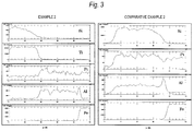
- Fig. 3 illustrates the results of analyzing the lines in the cross sectional direction from a supporting body to an overcoat layer (catalyst layer) for the catalysts of Example 2 and Comparative Example 2 after the durability test. From Fig. 3 , it is found that for the catalyst of Example 2, the most silicon was trapped on the overcoat layer including titania (Ti), and the silicon did not reach the catalyst layer (Pt). The activity of the catalyst layer was considered to be maintained by the trapping of silicon by the overcoat layer. Meanwhile, for the catalyst without the overcoat layer of Comparative Example 2, the silicon was accumulated on the catalyst layer (Pt), and the activity was considered to be decreased accordingly.
- Second Embodiment titania was applied as an overcoat layer, and the relation between the initial activity and the thickness (formation amount) of the overcoat layer was investigated.
- a catalyst layer was formed on a supporting body, and the content of titania in a titania sol solution was adjusted to prepare the catalyst having the changed thickness of the overcoat layer.
- the amount of platinum supported in the catalyst was 2 g/L and the amount of the inorganic oxide carrier was 80 g/L.
- the test content of the evaluations of the initial activity and durability for the prepared catalyst was the same as that in the first embodiment.
- Fig. 4 illustrates the results of evaluating the initial activities when the thickness of the overcoat layer is changed.
- the initial activity is evaluated in terms of purifying rate. It is known from these results that in the case of forming an overcoat layer, even though there was an increase in the temperature (catalyst inlet temperature) at which activity occurs, about 99% or more of the purifying rate was obtained. However, when the thickness of the overcoat layer was 63.7 ⁇ m (the formation amount of 240 g/L), the purifying rate was barely 99%. It can be said that the initial activity is an index that can determine the upper limit of the thickness of the overcoat layer. In this test range, there was no significant decrease in the activity. However, if the purifying rate was regarded to be important, it is expected that for about 70 ⁇ m of the thickness, the sufficient initial activity can be obtained.
- Third Embodiment Furthermore, the effect on durability by the thickness of the overcoat layer was investigated. As in the second embodiment, the content of titania in the titania sol solution was adjusted, and the catalyst having the changed thickness of the overcoat layer was prepared (the amount of platinum supported was 2 g/L and the amount of the inorganic oxide carrier was 80 g/L). Then, the test for evaluating durability was performed in the same operation as in the first embodiment.
- Fig. 5 illustrates the results of evaluating the activities after deterioration.
- the durability test results can be an index that can determine the lower limit of the thickness of the overcoat layer, but referring to Fig. 5 , there was the gap of the catalytic activities between 10.9 ⁇ m (the formation amount of 41 g/L) and 13.5 ⁇ m (the formation amount of 51 g/L) of the thickness of the overcoat layer. From this result, the overcoat layer having the thickness of 13 ⁇ m or more is considered to be preferable in terms of the durability for catalyst poisoning by Si.
- the catalyst poisoning by silicon can be avoided and the exhaust gases can be treated for a long period of time while the activity is maintained. Further, the present invention improves the configuration of catalyst itself, does not require any reactor for removing silicon on the front part of the catalyst, and therefore can contribute to the simplification of the configuration of exhaust gas purifying device.
- the present invention is effective for the exhaust gas purifying device in various factories in addition to a generating device such as a fuel cell.
Landscapes
- Chemical & Material Sciences (AREA)
- Engineering & Computer Science (AREA)
- Chemical Kinetics & Catalysis (AREA)
- Materials Engineering (AREA)
- Organic Chemistry (AREA)
- Environmental & Geological Engineering (AREA)
- Health & Medical Sciences (AREA)
- Biomedical Technology (AREA)
- Analytical Chemistry (AREA)
- General Chemical & Material Sciences (AREA)
- Oil, Petroleum & Natural Gas (AREA)
- Catalysts (AREA)
- Exhaust Gas Treatment By Means Of Catalyst (AREA)
Abstract
Description
- The present invention relates to an exhaust gas purifying catalyst, in which the exhaust gas includes a silicon compound and is an exhaust gas of a fuel cell system which has been widely used recently or exhaust gases from various factories.
- As an exhaust gas purifying catalyst for purifying exhaust of a fuel cell system or exhaust gases generated from various factories, that is, various factories such as painting, printing, a formation product, food, medical treatment, and chemistry, the catalyst which is prepared by applying a carrier (generally, called a wash coat) including an inorganic oxide such as alumina on a supporting body made of a metal or a ceramic material and by having a precious metal supported on the carrier to form a catalyst layer is used. Here, the exhaust gas to be treated often include a silicon compound other than hydrocarbon such as carbon monoxide, hydrogen, and other various VOCs (volatile organic compound) to be treated as an original object.
- The silicon compound in the exhaust gas is largely used for a cell stack containing an electrolyte in a fuel cell system, various seal parts, a ceramic insulation material, and the like. In various factories, in addition to the case in which the silicon compound is generated as by-product of manufacturing products, the silicon compound is contained in a lubricant, a releasing agent, a desiccant, a water repelling agent, a flame retardant, an insulating material, an adhesive, an antistatic agent, a sealant, and the like, and are directly influenced or are influenced by the atmosphere or temperature, thereby being volatilized and thus being mixed in an exhaust gas.
- The silicon compound in an exhaust gas has a problem of causing catalyst poisoning that reduces catalytic activity according to time for an exhaust gas purifying catalyst. It is believed that the catalyst poisoning by silicon is caused as a result that the silicon invaded into a catalyst layer (carrier layer) adheres to the active point of a precious metal. Further, since the precious metal catalyst does not have the detaching action of a silicon compound, the catalytic overall activity decreases by the accumulation of blocked active point.
- Here, as the countermeasure for catalyst poisoning caused by a silicon compound, there is a method of providing an absorbent of a silicon compound on the front part of the exhaust gas purifying catalyst (Patent Document 1). However, this method makes the configuration of an exhaust gas purifying device complicated, thereby increasing the cost for the device. Therefore, to simplify the configuration of the exhaust gas purifying device, it is known to provide an adsorption action by a silicon compound to the exhaust gas purifying catalyst itself. For example,
Patent Document 2 suggests the exhaust gas purifying catalyst applied with a catalyst composition containing the alumina or zeolite supported with a precious metal. -
- Patent Document 1:
-
JP 59-147623 A - Patent Document 2:
-
JP 4319222 B2 - The exhaust gas purifying catalyst having the ability for removing silicon, which is suggested in
Patent Document 2, is considered to have a certain effect by containing zeolite as a component having a silicon-absorption action in a catalyst layer. However, it is not so imaginable that the contact between silicon and a precious metal can be completely inhibited for the exhaust gas purifying catalyst. This is because that even though zeolite in the catalyst layer absorbs silicon, the whole silicon is not completely absorbed into the zeolite. Further, there is a possibility that the activity is slowly decreased by the accumulation of the blocked active point of a precious metal. In this regard, there still remains a question regarding whether or not the activity can be maintained for years because the exhaust gas purifying catalyst inPatent Document 2 is subjected to a test only for about several hundreds of hours. - For a period for maintaining the activity of an exhaust gas purifying catalyst, there has never been the catalyst that satisfies long-term durability, for example, a 10-year unit, for the exhausts in various factories. Further, since devices provided in a general home, like a fuel cell system, require maintenance-free characteristics for a 10-year unit, the devices require long-term activity maintenance. Therefore, an object of the present invention is to provide an exhaust gas purifying catalyst for purifying an exhaust gas containing silicon and can maintain longer-term activity compared to the related art.
- In order to achieve the above-described object, the present inventors tried to form an overcoat layer on a catalyst layer for covering the catalyst layer for fundamentally removing a contact between a silicon compound and a precious metal in the catalyst layer. The conventional exhaust gas purifying catalyst contains the absorption component of silicon in the catalyst layer, but the contact between a precious metal and a silicon compound cannot be removed. It can be said that the contact between the precious metal and the silicon and poisoning can be removed by setting an overcoat layer and then trapping the silicon compound by the overcoat layer.
- Meanwhile, for the configuration of the overcoat layer, when the overcoat layer simply covers a catalyst layer, the materials to be treated (for example, hydrocarbon such as carbon monoxide) in an exhaust gas does not reach the catalyst layer, and thus an original function as an exhaust gas purifying catalyst cannot be exhibited. In other words, it is required that the overcoat layer selectively traps only a silicon compound, and also allows the materials being treated in the exhaust gas to easily reach the catalyst layer. Therefore, the present inventors found zirconia and titania as a suitable material for the relevant overcoat layer, and thus completed the present invention.
- Specifically, the present invention provides an exhaust gas purifying catalyst for purifying an exhaust gas containing a silicon compound, the exhaust gas purifying catalyst including: a supporting body; and a catalyst layer formed on the supporting body and having a precious metal supported on an inorganic oxide carrier, wherein the exhaust gas purifying catalyst includes an overcoat layer containing at least one of zirconia and titania and is provided on the catalyst layer.
- Hereinafter, the present invention will be described in more detail. For the exhaust gas purifying catalyst according to the present invention, a catalyst layer formed on a supporting body is applied with the same configuration as that of the conventional catalyst layer. The catalyst layer is formed by having an inorganic oxide carrier with a precious metal supported on the inorganic oxide carrier. The precious metal of the catalyst layer is preferably one of platinum, palladium, rhodium, ruthenium, and iridium in terms of catalytic activity. The amount of the precious metal supported is preferably 0.1 to 30 g/L based on the volume of a supporting body.
- Further, the inorganic oxide as a carrier may be alumina, ceria, zirconia, titania, or a mixture or complex oxide thereof. The amount of the inorganic oxide carrier is preferably 60 to 200 g/L based on the volume of a supporting body.
- The present invention is characterized by forming an overcoat layer on a catalyst layer as described above. The overcoat layer includes at least any one of zirconia and titania. The overcoat layer blocks the direct contact between an exhaust gas to be treated and a catalyst layer, and fundamentally decreases the activity of an exhaust gas purifying catalyst. The inorganic oxide described above has effects of reducing a decrease in the activity and also trapping silicon.
- Further, the overcoat layer preferably has a thickness of 13 to 70 µm. The thickness of the overcoat layer does not highly affect the initial activity of a catalyst, but affects the activity after being used for a long period of time. For the overcoat layer having a thickness of less than 13 µm, the amount of silicon trapped is small, and the time for trapping silicon can be expected is short, thereby lacking durability. Therefore, the decrease in the activity of the overcoat layer becomes relatively larger after being used for a long period of time. Meanwhile, the overcoat layer having the thickness of larger than 70 µm affects the initial activity, and also leads to the blocking of cells and the cost increase. The more preferable thickness of the overcoat layer is 13 to 48 µm. Further, a silicon-trapping effect is exhibited by the overcoat layer, and thus, the overcoat layer has the effect regardless of a type of the activity of a catalyst layer.
- The catalyst layer and the overcoat layer as described above are formed on a suitable supporting body, and then, constitute an exhaust gas purifying catalyst. The supporting body is made of metal such as a stainless, and of ceramic. The supporting body having a honeycomb structure is preferable. The volume, size, and the like for a supporting body having a honeycomb structure are not particularly limited. The supporting body used has the volume of 0.01 to 20 L and the cell density of 100 to 800 cpsi in many cases. For example, when the overcoat layer in the preferable thickness range as described above is formed on the supporting body having the cell density of 260 cpsi, the overcoat layer is formed in the amount of 50 to 250 g/L based on the volume of the supporting body. Further, in this case, more preferable amount of the overcoat layer formed is 50 to 180 g/L.
- For preparing the exhaust gas purifying catalyst according to the present invention, a catalyst layer and an overcoat layer are formed on a supporting body sequentially. For forming the catalyst layer, a sol solution including an inorganic oxide is applied on a supporting body, and then, is suitably subjected to drying and heating. Then, a precious metal salt is absorbed by immersing the supporting body in a precious metal salt solution, and the supporting body is heated to support the precious metal particles. Further, the heating may be performed by immersing the supporting body in a sol solution including an inorganic oxide and a precious metal salt.
- For forming the overcoat layer, the sol solution containing at least one of zirconia and titania is applied on the supporting body having the catalyst layer. For forming the overcoat layer, the sol solution is applied and then the heating is suitably performed. The heating is preferably performed at 400°C to 700°C.
- The exhaust gas purifying catalyst according to the present invention is used for purifying an exhaust gas including a silicon compound. For the exhaust gas treatment, the exhaust gas is brought into contact with the exhaust gas purifying catalyst according to the present invention at a predetermined reaction temperature. At this time, the catalytic activity cannot be sufficiently obtained at the reaction temperature of 25°C or lower, and also the catalyst component is thermally deteriorated at 700°C or higher. Therefore, the catalyst inlet temperature is preferably 25°C to 700°C.
- The exhaust gas to be treated according to the present invention is not particularly limited as long as the exhaust gas contains a silicon compound. The silicon compound in the exhaust gas includes all of the silicon compounds without an organic group (hydride, hydroxide, halide, and the like) in addition to an organic silicon compound (siloxide, organic silane, organic silicon, and the like). Further, the materials to be treated in the exhaust gas are not particularly limited, and various exhaust gases, for example, VOC and hydrocarbon in the exhaust gases from various factories or carbon monoxide contained in an offgas or the like from a fuel cell system may be treated.
- As described above, the exhaust gas purifying catalyst according to the present invention can maintain the activity thereof by avoiding catalyst poisoning generated by silicon for purifying various exhaust gases including a silicon compound for a long period of time. The present invention is suitable for an exhaust gas-treating device that is a device requiring long-term maintenance-free characteristics like a domestic fuel cell system, and also, is effective for the exhaust gas purifying devices in various factories.
-
-
Fig. 1 is a view illustrating the results of evaluating catalytic initial characteristics of Examples 1 and 2 and Comparative Examples 1 and 2 according to a first embodiment. -
Fig. 2 is a view illustrating the catalytic activities before and after deterioration of Examples 1 and 2 and Comparative Examples 1 and 3 according to the first embodiment. -
Fig. 3 is a view illustrating the results of analyzing the lines of cross sections of the catalysts after deterioration of Example 2 and Comparative Example 2 according to the first embodiment. -
Fig. 4 is a view illustrating the results of evaluating the initial activities when the thickness of the overcoat layer according to a second embodiment is changed. -
Fig. 5 is a view illustrating the results of evaluating the activities after deterioration when the thickness of the overcoat layer according to a third embodiment is changed. - Hereinafter, the embodiments of the present invention will be described.
- First Embodiment: A stainless-steel metal honeycomb (φ 52 mm x
L 58 mm, a volume of 0.123 L, and a cell density of 260 cpsi) was used as a supporting body. This supporting body was immersed in 500 mL of a sol solution dispersed with 150 g of alumina, and was dried and burned to form an inorganic oxide carrier layer. Then, 500 mL (platinum mass: 0.25 g) of a nitric acid platinum solution (concentration: 0.05 wt%) was absorbed in the carrier layer, was dried, and then, was heated to support platinum to form a catalyst layer. At this time, the amount of platinum supported was 2 g/L. Further, the inorganic oxide carrier was 80 g/L. - Further, an overcoat layer was formed on the catalyst layer. As the overcoat layer, the supporting body having the catalyst layer as described above was immersed in 500 mL of a sol solution dispersed with 150 g of zirconia, and dried and heated to form the overcoat layer, thereby obtaining an exhaust gas purifying catalyst (Example 1). Further, the supporting body was immersed in 500 mL of sol solution dispersed with 80 g of titania, and was dried and burned in the same manner as described above to form the overcoat layer (Example 2). The amount of overcoat layer formed in these Examples was 60 g/L and the thickness of the overcoat layer was 16 µm.
- Comparative Example 1: For Comparative Examples for each of the above Examples, as the overcoat layer, alumina-ceria mixed oxide that was the same as an inorganic oxide carrier was applied. In the first embodiment, the supporting body having the catalyst layer was immersed in the sol solution that was the same as the sol solution when the carrier layer is formed, and was dried and heated to form the overcoat layer, thereby obtaining an exhaust gas purifying catalyst.
- Comparative Example 2: Further, as Comparative Example 2, the catalyst without an overcoat layer, which was the conventional exhaust gas catalyst, was prepared. For this catalyst, the catalyst having a catalyst layer in the first embodiment was used as it is for evaluating the characteristics.
- Further, for the catalysts in Examples 1 and 2 and Comparative Examples 1 and 2, the tests for evaluating the initial characteristics and durability were performed. For evaluating the initial characteristics, the test gas including carbon monoxide that simulated the off gas of SOFC was introduced into each of the catalysts to increase the temperature of catalyst, and then, the concentration of carbon monoxide of the gas exhausted from a catalyst outlet was measured. Then, the relation between the catalyst inlet temperature and the purification rate was measured. The test conditions were as follows.
- Test gas: CO (2000 ppm) + H2O (5%) (air balance)
- SV: 30,000 h-1
- Further, for the evaluation of durability, the deterioration test that stimulated the use period of ten years was performed to evaluate the catalytic activity after deterioration. For the deterioration test of catalyst, the catalyst was exposed to the gas prepared by mixing tetraethoxysilane in the gas having 10% of 02, 10% of H2O, and 80% of N2 so as to deteriorate the catalyst. The concentration of tetraethoxysilane and the exposure time were determined as follows. The amount of silica precipitated in the catalyst was predicted based on a vapor pressure of orthosilicic acid, the flow amount of exhaust gas, and the operating time at the exhaust gas purifying catalyst temperature in the process of producing orthosilicic acid under the high-temperature and vapor atmosphere by silica included in a ceramic insulation material in a SOFC stack, and again, precipitating orthosilicic acid as silica in the exhaust gas purifying catalyst. Then, the amount of silica was set to be the same as the predicted amount of silica. As for other conditions, the test was performed under the following conditions.
- SV (Space velocity: the amount of passed gas per catalytic capacity): 30,000 h-1
- Catalyst inlet temperature: 250°C
- Deterioration time: 66 hours
- Then, the catalytic activity in the catalyst after deterioration was evaluated. The test gas that stimulated the off gas of SOFC was introduced into each of the catalysts to measure the relation between the catalytic center temperature and the concentration of carbon monoxide in the exhausted gas. The test conditions were as follows. Note that, for this activity evaluation, the initial activity before deterioration was also measured under the same conditions.
- Test gas: CO (2000 ppm) + O2 (about 10%) (Humidified air balance)
- SV: 30,000 h-1
-
Fig. 1 illustrates the results of evaluating catalytic initial characteristics of Examples 1 and 2 and Comparative Examples 1 and 2. When comparing Examples 1 and 2 and Comparative Examples 1 and 2, basically, the formation of an overcoat layer on a catalyst layer allowed the catalyst inlet temperature to increase, thereby decreasing the initial activity of the catalyst. The reason is that the inhibition on reaching the materials (carbon monoxide) to be treated into the catalyst layer is not completely avoided by the overcoat layer. However, when zirconia (Example 1) and titania (Example 2) were applied as the overcoat layer, the decrease of the activity was relatively reduced. In contrast, the oxide (alumina + ceria) of Comparative Example 1 exhibited a significant decrease in the activity, and thus, was undesirable as an exhaust gas purifying catalyst in terms of the initial activity. In other words, it can be confirmed that not all kinds of oxides are preferably used as the component materials of the overcoat layer, but it is required to properly select the materials. - Therefore, in the following durability test, the catalysts of Examples 1 and 2 and Comparative Example 2 were tested. Further, for Comparative Example 2, the catalyst was prepared with the doubled amount of the platinum supported, and evaluated (Comparative Example 3).
Fig. 2 illustrates the catalytic activities before and after deterioration as the results of the durability test. - Referring to
Fig. 2 , it is found the activities of all the catalysts decreased after the deterioration test. However, for the catalysts having the overcoat layers of Examples 1 and 2, the decrease in the activity was inhibited as compared with the catalyst without the overcoat layer, which had the same amount of platinum, of Comparative Example 2. From these results, it was confirmed that the catalyst poisoning by the deterioration test was reduced by the formation of the overcoat layer. Further, although the catalyst having the doubled amount of platinum of Comparative Example 3 has excellent initial activity, the decrease in the activity of the catalyst after deterioration is great. The catalyst of Comparative Example 3 has significantly increased amount of platinum and thus it is a matter of course that the initial activity of the catalyst is large. However, a large amount of a precious metal, which greatly affects the cost of an exhaust gas purifying catalyst, is undesirable in terms of the cost. Further, even though the catalyst of Comparative Example 3 has excellent initial activity, the catalyst poisoning as time passed is not avoided. Therefore, for planning practical and fundamental countermeasure to the catalyst poisoning by silicon, it was confirmed that the setting of an overcoat layer is effective. -
Fig. 3 illustrates the results of analyzing the lines in the cross sectional direction from a supporting body to an overcoat layer (catalyst layer) for the catalysts of Example 2 and Comparative Example 2 after the durability test. FromFig. 3 , it is found that for the catalyst of Example 2, the most silicon was trapped on the overcoat layer including titania (Ti), and the silicon did not reach the catalyst layer (Pt). The activity of the catalyst layer was considered to be maintained by the trapping of silicon by the overcoat layer. Meanwhile, for the catalyst without the overcoat layer of Comparative Example 2, the silicon was accumulated on the catalyst layer (Pt), and the activity was considered to be decreased accordingly. - Second Embodiment: In this embodiment, titania was applied as an overcoat layer, and the relation between the initial activity and the thickness (formation amount) of the overcoat layer was investigated. With the same operation as in the first embodiment, a catalyst layer was formed on a supporting body, and the content of titania in a titania sol solution was adjusted to prepare the catalyst having the changed thickness of the overcoat layer. Note that, also in this embodiment, the amount of platinum supported in the catalyst was 2 g/L and the amount of the inorganic oxide carrier was 80 g/L. The test content of the evaluations of the initial activity and durability for the prepared catalyst was the same as that in the first embodiment.
-
Fig. 4 illustrates the results of evaluating the initial activities when the thickness of the overcoat layer is changed. In this embodiment, the initial activity is evaluated in terms of purifying rate. It is known from these results that in the case of forming an overcoat layer, even though there was an increase in the temperature (catalyst inlet temperature) at which activity occurs, about 99% or more of the purifying rate was obtained. However, when the thickness of the overcoat layer was 63.7 µm (the formation amount of 240 g/L), the purifying rate was barely 99%. It can be said that the initial activity is an index that can determine the upper limit of the thickness of the overcoat layer. In this test range, there was no significant decrease in the activity. However, if the purifying rate was regarded to be important, it is expected that for about 70 µm of the thickness, the sufficient initial activity can be obtained. - Third Embodiment: Furthermore, the effect on durability by the thickness of the overcoat layer was investigated. As in the second embodiment, the content of titania in the titania sol solution was adjusted, and the catalyst having the changed thickness of the overcoat layer was prepared (the amount of platinum supported was 2 g/L and the amount of the inorganic oxide carrier was 80 g/L). Then, the test for evaluating durability was performed in the same operation as in the first embodiment.
-
Fig. 5 illustrates the results of evaluating the activities after deterioration. The durability test results can be an index that can determine the lower limit of the thickness of the overcoat layer, but referring toFig. 5 , there was the gap of the catalytic activities between 10.9 µm (the formation amount of 41 g/L) and 13.5 µm (the formation amount of 51 g/L) of the thickness of the overcoat layer. From this result, the overcoat layer having the thickness of 13 µm or more is considered to be preferable in terms of the durability for catalyst poisoning by Si. - According to the present invention, for purifying various exhaust gases including a silicon compound, the catalyst poisoning by silicon can be avoided and the exhaust gases can be treated for a long period of time while the activity is maintained. Further, the present invention improves the configuration of catalyst itself, does not require any reactor for removing silicon on the front part of the catalyst, and therefore can contribute to the simplification of the configuration of exhaust gas purifying device. The present invention is effective for the exhaust gas purifying device in various factories in addition to a generating device such as a fuel cell.
Claims (5)
- An exhaust gas purifying catalyst for purifying an exhaust gas containing a silicon compound, comprising:a supporting body; anda catalyst layer formed on the supporting body and having a precious metal supported on an inorganic oxide carrier, whereinthe exhaust gas purifying catalyst has an overcoat layer containing at least one of zirconia and titania on the catalyst layer.
- The exhaust gas purifying catalyst according to claim 1, wherein a thickness of the overcoat layer is 13 to 70 µm.
- The exhaust gas purifying catalyst according to claim 1 or 2, wherein the precious metal of the catalyst layer comprises any one of platinum, palladium, rhodium, ruthenium, and iridium.
- The exhaust gas purifying catalyst according to any one of claims 1 to 3, wherein the inorganic oxide of the catalyst layer comprises a simple substance, a mixture, or a complex oxide of any one of alumina, ceria, zirconia, and titania.
- An exhaust gas purifying method for purifying an exhaust gas containing a silicon compound, the method comprising:bringing the exhaust gas into contact with the exhaust gas purifying catalyst defined in any one of claims 1 to 4 at 25°C to 700°C of a reaction temperature.
Applications Claiming Priority (2)
| Application Number | Priority Date | Filing Date | Title |
|---|---|---|---|
| JP2013071050A JP5918718B2 (en) | 2013-03-29 | 2013-03-29 | Exhaust gas treatment catalyst for purifying exhaust gas containing silicon compound |
| PCT/JP2014/057753 WO2014156951A1 (en) | 2013-03-29 | 2014-03-20 | Exhaust gas treating catalyst for purifying exhaust gas containing silicon compound |
Publications (3)
| Publication Number | Publication Date |
|---|---|
| EP2979754A1 true EP2979754A1 (en) | 2016-02-03 |
| EP2979754A4 EP2979754A4 (en) | 2016-11-23 |
| EP2979754B1 EP2979754B1 (en) | 2022-02-23 |
Family
ID=51623930
Family Applications (1)
| Application Number | Title | Priority Date | Filing Date |
|---|---|---|---|
| EP14776355.1A Active EP2979754B1 (en) | 2013-03-29 | 2014-03-20 | Exhaust gas treating catalyst for purifying exhaust gas containing silicon compound |
Country Status (3)
| Country | Link |
|---|---|
| EP (1) | EP2979754B1 (en) |
| JP (1) | JP5918718B2 (en) |
| WO (1) | WO2014156951A1 (en) |
Families Citing this family (1)
| Publication number | Priority date | Publication date | Assignee | Title |
|---|---|---|---|---|
| JP6878591B2 (en) * | 2017-07-27 | 2021-05-26 | 京セラ株式会社 | Fuel cell device |
Family Cites Families (10)
| Publication number | Priority date | Publication date | Assignee | Title |
|---|---|---|---|---|
| JPS59147623A (en) | 1983-02-10 | 1984-08-24 | Toray Ind Inc | Process and agent for treating waste gas containing silicone |
| JP2897367B2 (en) * | 1990-01-12 | 1999-05-31 | 日本特殊陶業株式会社 | Poisoning prevention body, catalyst with poisoning prevention layer, and exhaust gas purification device |
| JPH10148306A (en) * | 1996-11-19 | 1998-06-02 | Matsushita Electric Ind Co Ltd | Catalytic combustion device and combustion catalyst |
| JP2004066126A (en) * | 2002-08-07 | 2004-03-04 | Babcock Hitachi Kk | Catalyst for purification of exhaust gas containing silicon |
| JP4329432B2 (en) * | 2003-07-15 | 2009-09-09 | トヨタ自動車株式会社 | Exhaust gas purification catalyst |
| CN1938089B (en) | 2004-03-30 | 2010-12-08 | 日挥通用株式会社 | Catalyst for purifying exhaust gas and method for purifying exhaust gas |
| JP5024883B2 (en) * | 2008-02-06 | 2012-09-12 | トヨタ自動車株式会社 | Exhaust gas purification catalyst |
| US8337791B2 (en) * | 2008-12-03 | 2012-12-25 | Daiichi Kigenso Kagaku Kogyo Co., Ltd. | Exhaust gas purification catalyst, exhaust gas purification apparatus using the same and exhaust gas purification method |
| WO2012132678A1 (en) * | 2011-03-31 | 2012-10-04 | エヌ・イー ケムキャット株式会社 | Ammonia oxidation catalyst, exhaust gas purification device using same, and exhaust gas purification method |
| JP4989771B1 (en) * | 2011-04-15 | 2012-08-01 | 田中貴金属工業株式会社 | Regeneration method of exhaust gas purification catalyst |
-
2013
- 2013-03-29 JP JP2013071050A patent/JP5918718B2/en active Active
-
2014
- 2014-03-20 EP EP14776355.1A patent/EP2979754B1/en active Active
- 2014-03-20 WO PCT/JP2014/057753 patent/WO2014156951A1/en not_active Ceased
Also Published As
| Publication number | Publication date |
|---|---|
| EP2979754B1 (en) | 2022-02-23 |
| JP5918718B2 (en) | 2016-05-18 |
| WO2014156951A1 (en) | 2014-10-02 |
| JP2014193446A (en) | 2014-10-09 |
| EP2979754A4 (en) | 2016-11-23 |
Similar Documents
| Publication | Publication Date | Title |
|---|---|---|
| Li et al. | Role of water on the structure of palladium for complete oxidation of methane | |
| Jing et al. | Catalytic decomposition of N2O in the presence of O2 through redox of Rh oxide in a RhO x/ZrO2 catalyst | |
| Olsson et al. | A kinetic study of oxygen adsorption/desorption and NO oxidation over Pt/Al2O3 catalysts | |
| Lindholm et al. | NOx storage and reduction over Pt based catalysts with hydrogen as the reducing agent: Influence of H2O and CO2 | |
| RU2657082C2 (en) | Method and catalyst for simultaneous removal of carbon monoxide and nitrogen oxides from flue or exhaust gas | |
| TWI776842B (en) | Low cost oxidation catalysts for voc and halogenated voc emission control | |
| Presto et al. | Noble metal catalysts for mercury oxidation in utility flue gas | |
| CN1097721C (en) | Catalyst system and recombination device for recombining hydrogen and oxygen, in particular for nuclear power station | |
| Xu et al. | Indoor formaldehyde removal by thermal catalyst: kinetic characteristics, key parameters, and temperature influence | |
| Jing et al. | Promotional effect of Ag on the catalytic decomposition of N2O in the presence of O2 over the Al2O3-supported Rh catalyst | |
| Liu et al. | The critical roles of hydrophobicity, surface Ru 0 and active O 2−/O 2 2− sites on toluene combustion on Ru/ZSM-5 with varied Si/Al ratios | |
| CN115155579A (en) | Reductive noble metal loaded manganese oxide catalyst for catalytic combustion of multi-component organic waste gas and preparation method thereof | |
| JP4319222B2 (en) | Exhaust gas purification catalyst and exhaust gas purification method | |
| JP5564519B2 (en) | Method for treating radioactive gas waste, treatment facility, impurity removing material, and method for decomposing and removing siloxane | |
| EP2979754B1 (en) | Exhaust gas treating catalyst for purifying exhaust gas containing silicon compound | |
| EP3372310B1 (en) | Use of a purification catalyst for purifying a gas inside a polymer film production furnace and a method for purifying a gas inside a polymer film production furnace | |
| US4548911A (en) | Regeneration of phosphorus poisoned automotive catalysts | |
| Imanaka et al. | Advanced materials for environmental catalysts | |
| Wei et al. | The Mechanism of Low‐Temperature CO Oxidation on IB Group Metals and Metal Oxides | |
| JP4304385B2 (en) | Catalyst for oxidation removal of methane in exhaust gas and method for oxidation removal of methane in exhaust gas | |
| Baktygerey et al. | Palladium catalysts supported on carbonized porous silicon for H 2/O 2 recombination. | |
| JP2003275587A (en) | Catalyst for selective oxidation of carbon monoxide and hydrogen purifier using it | |
| JP5628487B2 (en) | Nitrogen oxide purification method | |
| US20140235434A1 (en) | Exhaust gas purification catalyst and method for producing the same | |
| JP2006167501A (en) | Reforming catalyst, hydrogen generator and fuel cell system |
Legal Events
| Date | Code | Title | Description |
|---|---|---|---|
| PUAI | Public reference made under article 153(3) epc to a published international application that has entered the european phase |
Free format text: ORIGINAL CODE: 0009012 |
|
| 17P | Request for examination filed |
Effective date: 20151013 |
|
| AK | Designated contracting states |
Kind code of ref document: A1 Designated state(s): AL AT BE BG CH CY CZ DE DK EE ES FI FR GB GR HR HU IE IS IT LI LT LU LV MC MK MT NL NO PL PT RO RS SE SI SK SM TR |
|
| AX | Request for extension of the european patent |
Extension state: BA ME |
|
| DAX | Request for extension of the european patent (deleted) | ||
| RIN1 | Information on inventor provided before grant (corrected) |
Inventor name: AMANO, TAKASHI Inventor name: MURAYAMA, KEIJI Inventor name: SHIRAISHI, HIROKAZU Inventor name: KIKUHARA, SHUNJI Inventor name: UNNO, TETSUYA |
|
| A4 | Supplementary search report drawn up and despatched |
Effective date: 20161024 |
|
| RIC1 | Information provided on ipc code assigned before grant |
Ipc: B01J 33/00 20060101ALI20161018BHEP Ipc: B01J 23/42 20060101AFI20161018BHEP Ipc: B01D 53/94 20060101ALI20161018BHEP |
|
| STAA | Information on the status of an ep patent application or granted ep patent |
Free format text: STATUS: EXAMINATION IS IN PROGRESS |
|
| 17Q | First examination report despatched |
Effective date: 20191217 |
|
| REG | Reference to a national code |
Ref country code: DE Ref legal event code: R079 Ref document number: 602014082591 Country of ref document: DE Free format text: PREVIOUS MAIN CLASS: B01J0023420000 Ipc: B01J0033000000 |
|
| GRAP | Despatch of communication of intention to grant a patent |
Free format text: ORIGINAL CODE: EPIDOSNIGR1 |
|
| STAA | Information on the status of an ep patent application or granted ep patent |
Free format text: STATUS: GRANT OF PATENT IS INTENDED |
|
| RIC1 | Information provided on ipc code assigned before grant |
Ipc: B01J 23/40 20060101ALI20210901BHEP Ipc: B01J 23/42 20060101ALI20210901BHEP Ipc: B01D 53/86 20060101ALI20210901BHEP Ipc: B01J 33/00 20060101AFI20210901BHEP |
|
| INTG | Intention to grant announced |
Effective date: 20210920 |
|
| GRAS | Grant fee paid |
Free format text: ORIGINAL CODE: EPIDOSNIGR3 |
|
| GRAA | (expected) grant |
Free format text: ORIGINAL CODE: 0009210 |
|
| STAA | Information on the status of an ep patent application or granted ep patent |
Free format text: STATUS: THE PATENT HAS BEEN GRANTED |
|
| RAP3 | Party data changed (applicant data changed or rights of an application transferred) |
Owner name: AISIN CORPORATION Owner name: TANAKA KIKINZOKU KOGYO K.K. |
|
| AK | Designated contracting states |
Kind code of ref document: B1 Designated state(s): AL AT BE BG CH CY CZ DE DK EE ES FI FR GB GR HR HU IE IS IT LI LT LU LV MC MK MT NL NO PL PT RO RS SE SI SK SM TR |
|
| REG | Reference to a national code |
Ref country code: GB Ref legal event code: FG4D |
|
| REG | Reference to a national code |
Ref country code: CH Ref legal event code: EP |
|
| REG | Reference to a national code |
Ref country code: DE Ref legal event code: R096 Ref document number: 602014082591 Country of ref document: DE |
|
| REG | Reference to a national code |
Ref country code: AT Ref legal event code: REF Ref document number: 1470010 Country of ref document: AT Kind code of ref document: T Effective date: 20220315 |
|
| REG | Reference to a national code |
Ref country code: IE Ref legal event code: FG4D |
|
| REG | Reference to a national code |
Ref country code: LT Ref legal event code: MG9D |
|
| REG | Reference to a national code |
Ref country code: NL Ref legal event code: MP Effective date: 20220223 |
|
| REG | Reference to a national code |
Ref country code: AT Ref legal event code: MK05 Ref document number: 1470010 Country of ref document: AT Kind code of ref document: T Effective date: 20220223 |
|
| PG25 | Lapsed in a contracting state [announced via postgrant information from national office to epo] |
Ref country code: SE Free format text: LAPSE BECAUSE OF FAILURE TO SUBMIT A TRANSLATION OF THE DESCRIPTION OR TO PAY THE FEE WITHIN THE PRESCRIBED TIME-LIMIT Effective date: 20220223 Ref country code: RS Free format text: LAPSE BECAUSE OF FAILURE TO SUBMIT A TRANSLATION OF THE DESCRIPTION OR TO PAY THE FEE WITHIN THE PRESCRIBED TIME-LIMIT Effective date: 20220223 Ref country code: PT Free format text: LAPSE BECAUSE OF FAILURE TO SUBMIT A TRANSLATION OF THE DESCRIPTION OR TO PAY THE FEE WITHIN THE PRESCRIBED TIME-LIMIT Effective date: 20220623 Ref country code: NO Free format text: LAPSE BECAUSE OF FAILURE TO SUBMIT A TRANSLATION OF THE DESCRIPTION OR TO PAY THE FEE WITHIN THE PRESCRIBED TIME-LIMIT Effective date: 20220523 Ref country code: NL Free format text: LAPSE BECAUSE OF FAILURE TO SUBMIT A TRANSLATION OF THE DESCRIPTION OR TO PAY THE FEE WITHIN THE PRESCRIBED TIME-LIMIT Effective date: 20220223 Ref country code: LT Free format text: LAPSE BECAUSE OF FAILURE TO SUBMIT A TRANSLATION OF THE DESCRIPTION OR TO PAY THE FEE WITHIN THE PRESCRIBED TIME-LIMIT Effective date: 20220223 Ref country code: HR Free format text: LAPSE BECAUSE OF FAILURE TO SUBMIT A TRANSLATION OF THE DESCRIPTION OR TO PAY THE FEE WITHIN THE PRESCRIBED TIME-LIMIT Effective date: 20220223 Ref country code: ES Free format text: LAPSE BECAUSE OF FAILURE TO SUBMIT A TRANSLATION OF THE DESCRIPTION OR TO PAY THE FEE WITHIN THE PRESCRIBED TIME-LIMIT Effective date: 20220223 Ref country code: BG Free format text: LAPSE BECAUSE OF FAILURE TO SUBMIT A TRANSLATION OF THE DESCRIPTION OR TO PAY THE FEE WITHIN THE PRESCRIBED TIME-LIMIT Effective date: 20220523 |
|
| PG25 | Lapsed in a contracting state [announced via postgrant information from national office to epo] |
Ref country code: PL Free format text: LAPSE BECAUSE OF FAILURE TO SUBMIT A TRANSLATION OF THE DESCRIPTION OR TO PAY THE FEE WITHIN THE PRESCRIBED TIME-LIMIT Effective date: 20220223 Ref country code: LV Free format text: LAPSE BECAUSE OF FAILURE TO SUBMIT A TRANSLATION OF THE DESCRIPTION OR TO PAY THE FEE WITHIN THE PRESCRIBED TIME-LIMIT Effective date: 20220223 Ref country code: GR Free format text: LAPSE BECAUSE OF FAILURE TO SUBMIT A TRANSLATION OF THE DESCRIPTION OR TO PAY THE FEE WITHIN THE PRESCRIBED TIME-LIMIT Effective date: 20220524 Ref country code: FI Free format text: LAPSE BECAUSE OF FAILURE TO SUBMIT A TRANSLATION OF THE DESCRIPTION OR TO PAY THE FEE WITHIN THE PRESCRIBED TIME-LIMIT Effective date: 20220223 Ref country code: AT Free format text: LAPSE BECAUSE OF FAILURE TO SUBMIT A TRANSLATION OF THE DESCRIPTION OR TO PAY THE FEE WITHIN THE PRESCRIBED TIME-LIMIT Effective date: 20220223 |
|
| PG25 | Lapsed in a contracting state [announced via postgrant information from national office to epo] |
Ref country code: IS Free format text: LAPSE BECAUSE OF FAILURE TO SUBMIT A TRANSLATION OF THE DESCRIPTION OR TO PAY THE FEE WITHIN THE PRESCRIBED TIME-LIMIT Effective date: 20220623 |
|
| PG25 | Lapsed in a contracting state [announced via postgrant information from national office to epo] |
Ref country code: SM Free format text: LAPSE BECAUSE OF FAILURE TO SUBMIT A TRANSLATION OF THE DESCRIPTION OR TO PAY THE FEE WITHIN THE PRESCRIBED TIME-LIMIT Effective date: 20220223 Ref country code: SK Free format text: LAPSE BECAUSE OF FAILURE TO SUBMIT A TRANSLATION OF THE DESCRIPTION OR TO PAY THE FEE WITHIN THE PRESCRIBED TIME-LIMIT Effective date: 20220223 Ref country code: RO Free format text: LAPSE BECAUSE OF FAILURE TO SUBMIT A TRANSLATION OF THE DESCRIPTION OR TO PAY THE FEE WITHIN THE PRESCRIBED TIME-LIMIT Effective date: 20220223 Ref country code: EE Free format text: LAPSE BECAUSE OF FAILURE TO SUBMIT A TRANSLATION OF THE DESCRIPTION OR TO PAY THE FEE WITHIN THE PRESCRIBED TIME-LIMIT Effective date: 20220223 Ref country code: DK Free format text: LAPSE BECAUSE OF FAILURE TO SUBMIT A TRANSLATION OF THE DESCRIPTION OR TO PAY THE FEE WITHIN THE PRESCRIBED TIME-LIMIT Effective date: 20220223 Ref country code: CZ Free format text: LAPSE BECAUSE OF FAILURE TO SUBMIT A TRANSLATION OF THE DESCRIPTION OR TO PAY THE FEE WITHIN THE PRESCRIBED TIME-LIMIT Effective date: 20220223 |
|
| REG | Reference to a national code |
Ref country code: CH Ref legal event code: PL |
|
| REG | Reference to a national code |
Ref country code: DE Ref legal event code: R097 Ref document number: 602014082591 Country of ref document: DE |
|
| PG25 | Lapsed in a contracting state [announced via postgrant information from national office to epo] |
Ref country code: MC Free format text: LAPSE BECAUSE OF FAILURE TO SUBMIT A TRANSLATION OF THE DESCRIPTION OR TO PAY THE FEE WITHIN THE PRESCRIBED TIME-LIMIT Effective date: 20220223 Ref country code: AL Free format text: LAPSE BECAUSE OF FAILURE TO SUBMIT A TRANSLATION OF THE DESCRIPTION OR TO PAY THE FEE WITHIN THE PRESCRIBED TIME-LIMIT Effective date: 20220223 |
|
| REG | Reference to a national code |
Ref country code: BE Ref legal event code: MM Effective date: 20220331 |
|
| PLBE | No opposition filed within time limit |
Free format text: ORIGINAL CODE: 0009261 |
|
| STAA | Information on the status of an ep patent application or granted ep patent |
Free format text: STATUS: NO OPPOSITION FILED WITHIN TIME LIMIT |
|
| GBPC | Gb: european patent ceased through non-payment of renewal fee |
Effective date: 20220523 |
|
| PG25 | Lapsed in a contracting state [announced via postgrant information from national office to epo] |
Ref country code: LU Free format text: LAPSE BECAUSE OF NON-PAYMENT OF DUE FEES Effective date: 20220320 Ref country code: LI Free format text: LAPSE BECAUSE OF NON-PAYMENT OF DUE FEES Effective date: 20220331 Ref country code: IE Free format text: LAPSE BECAUSE OF NON-PAYMENT OF DUE FEES Effective date: 20220320 Ref country code: FR Free format text: LAPSE BECAUSE OF NON-PAYMENT OF DUE FEES Effective date: 20220423 Ref country code: CH Free format text: LAPSE BECAUSE OF NON-PAYMENT OF DUE FEES Effective date: 20220331 |
|
| 26N | No opposition filed |
Effective date: 20221124 |
|
| PG25 | Lapsed in a contracting state [announced via postgrant information from national office to epo] |
Ref country code: SI Free format text: LAPSE BECAUSE OF FAILURE TO SUBMIT A TRANSLATION OF THE DESCRIPTION OR TO PAY THE FEE WITHIN THE PRESCRIBED TIME-LIMIT Effective date: 20220223 Ref country code: BE Free format text: LAPSE BECAUSE OF NON-PAYMENT OF DUE FEES Effective date: 20220331 |
|
| PG25 | Lapsed in a contracting state [announced via postgrant information from national office to epo] |
Ref country code: GB Free format text: LAPSE BECAUSE OF NON-PAYMENT OF DUE FEES Effective date: 20220523 |
|
| PG25 | Lapsed in a contracting state [announced via postgrant information from national office to epo] |
Ref country code: IT Free format text: LAPSE BECAUSE OF FAILURE TO SUBMIT A TRANSLATION OF THE DESCRIPTION OR TO PAY THE FEE WITHIN THE PRESCRIBED TIME-LIMIT Effective date: 20220223 |
|
| PG25 | Lapsed in a contracting state [announced via postgrant information from national office to epo] |
Ref country code: HU Free format text: LAPSE BECAUSE OF FAILURE TO SUBMIT A TRANSLATION OF THE DESCRIPTION OR TO PAY THE FEE WITHIN THE PRESCRIBED TIME-LIMIT; INVALID AB INITIO Effective date: 20140320 |
|
| PG25 | Lapsed in a contracting state [announced via postgrant information from national office to epo] |
Ref country code: MK Free format text: LAPSE BECAUSE OF FAILURE TO SUBMIT A TRANSLATION OF THE DESCRIPTION OR TO PAY THE FEE WITHIN THE PRESCRIBED TIME-LIMIT Effective date: 20220223 Ref country code: CY Free format text: LAPSE BECAUSE OF FAILURE TO SUBMIT A TRANSLATION OF THE DESCRIPTION OR TO PAY THE FEE WITHIN THE PRESCRIBED TIME-LIMIT Effective date: 20220223 |
|
| PG25 | Lapsed in a contracting state [announced via postgrant information from national office to epo] |
Ref country code: MT Free format text: LAPSE BECAUSE OF FAILURE TO SUBMIT A TRANSLATION OF THE DESCRIPTION OR TO PAY THE FEE WITHIN THE PRESCRIBED TIME-LIMIT Effective date: 20220223 |
|
| PG25 | Lapsed in a contracting state [announced via postgrant information from national office to epo] |
Ref country code: TR Free format text: LAPSE BECAUSE OF FAILURE TO SUBMIT A TRANSLATION OF THE DESCRIPTION OR TO PAY THE FEE WITHIN THE PRESCRIBED TIME-LIMIT Effective date: 20220223 |
|
| PGFP | Annual fee paid to national office [announced via postgrant information from national office to epo] |
Ref country code: DE Payment date: 20260319 Year of fee payment: 13 |