EP2979747A1 - Ceramic separation membrane structure and method for producing same - Google Patents
Ceramic separation membrane structure and method for producing same Download PDFInfo
- Publication number
- EP2979747A1 EP2979747A1 EP14774431.2A EP14774431A EP2979747A1 EP 2979747 A1 EP2979747 A1 EP 2979747A1 EP 14774431 A EP14774431 A EP 14774431A EP 2979747 A1 EP2979747 A1 EP 2979747A1
- Authority
- EP
- European Patent Office
- Prior art keywords
- separation membrane
- ceramic
- membrane structure
- zeolite
- porous body
- Prior art date
- Legal status (The legal status is an assumption and is not a legal conclusion. Google has not performed a legal analysis and makes no representation as to the accuracy of the status listed.)
- Withdrawn
Links
- 239000012528 membrane Substances 0.000 title claims abstract description 151
- 238000000926 separation method Methods 0.000 title claims abstract description 131
- 239000000919 ceramic Substances 0.000 title claims abstract description 65
- 238000004519 manufacturing process Methods 0.000 title claims abstract description 19
- VYPSYNLAJGMNEJ-UHFFFAOYSA-N Silicium dioxide Chemical compound O=[Si]=O VYPSYNLAJGMNEJ-UHFFFAOYSA-N 0.000 claims abstract description 76
- 239000010457 zeolite Substances 0.000 claims abstract description 65
- 229910021536 Zeolite Inorganic materials 0.000 claims abstract description 63
- HNPSIPDUKPIQMN-UHFFFAOYSA-N dioxosilane;oxo(oxoalumanyloxy)alumane Chemical compound O=[Si]=O.O=[Al]O[Al]=O HNPSIPDUKPIQMN-UHFFFAOYSA-N 0.000 claims abstract description 63
- 230000008439 repair process Effects 0.000 claims abstract description 40
- 239000000377 silicon dioxide Substances 0.000 claims abstract description 36
- 239000000463 material Substances 0.000 claims abstract description 34
- 238000000034 method Methods 0.000 claims description 34
- 238000010438 heat treatment Methods 0.000 claims description 10
- 230000018044 dehydration Effects 0.000 claims description 8
- 238000006297 dehydration reaction Methods 0.000 claims description 8
- 238000000151 deposition Methods 0.000 claims description 8
- 238000009833 condensation Methods 0.000 claims description 7
- 230000005494 condensation Effects 0.000 claims description 7
- 230000007062 hydrolysis Effects 0.000 claims description 7
- 238000006460 hydrolysis reaction Methods 0.000 claims description 7
- 238000010304 firing Methods 0.000 claims description 5
- 125000000954 2-hydroxyethyl group Chemical group [H]C([*])([H])C([H])([H])O[H] 0.000 claims description 4
- 239000006087 Silane Coupling Agent Substances 0.000 claims description 4
- 150000001875 compounds Chemical class 0.000 claims description 4
- 230000035699 permeability Effects 0.000 abstract description 5
- 125000000123 silicon containing inorganic group Chemical group 0.000 abstract description 5
- 230000009467 reduction Effects 0.000 abstract description 3
- 239000000758 substrate Substances 0.000 description 42
- 239000012530 fluid Substances 0.000 description 36
- QTBSBXVTEAMEQO-UHFFFAOYSA-N Acetic acid Chemical compound CC(O)=O QTBSBXVTEAMEQO-UHFFFAOYSA-N 0.000 description 21
- 239000013078 crystal Substances 0.000 description 20
- 239000002994 raw material Substances 0.000 description 18
- XLYOFNOQVPJJNP-UHFFFAOYSA-N water Substances O XLYOFNOQVPJJNP-UHFFFAOYSA-N 0.000 description 18
- 239000000203 mixture Substances 0.000 description 15
- 239000002245 particle Substances 0.000 description 14
- 239000003795 chemical substances by application Substances 0.000 description 10
- 230000007547 defect Effects 0.000 description 10
- 238000010586 diagram Methods 0.000 description 10
- 239000011148 porous material Substances 0.000 description 10
- 239000002002 slurry Substances 0.000 description 10
- LFQSCWFLJHTTHZ-UHFFFAOYSA-N Ethanol Chemical compound CCO LFQSCWFLJHTTHZ-UHFFFAOYSA-N 0.000 description 9
- 238000001027 hydrothermal synthesis Methods 0.000 description 8
- 230000002950 deficient Effects 0.000 description 7
- 239000012527 feed solution Substances 0.000 description 7
- 239000007788 liquid Substances 0.000 description 7
- 230000008569 process Effects 0.000 description 7
- 239000000243 solution Substances 0.000 description 7
- 229910001220 stainless steel Inorganic materials 0.000 description 7
- 239000010935 stainless steel Substances 0.000 description 7
- DKNWSYNQZKUICI-UHFFFAOYSA-N amantadine Chemical compound C1C(C2)CC3CC2CC1(N)C3 DKNWSYNQZKUICI-UHFFFAOYSA-N 0.000 description 6
- 239000012298 atmosphere Substances 0.000 description 6
- 230000004907 flux Effects 0.000 description 6
- 239000007789 gas Substances 0.000 description 6
- 238000010899 nucleation Methods 0.000 description 6
- 238000002360 preparation method Methods 0.000 description 5
- 239000000047 product Substances 0.000 description 5
- 238000007789 sealing Methods 0.000 description 5
- 238000012360 testing method Methods 0.000 description 5
- GWEVSGVZZGPLCZ-UHFFFAOYSA-N Titan oxide Chemical compound O=[Ti]=O GWEVSGVZZGPLCZ-UHFFFAOYSA-N 0.000 description 4
- 238000002441 X-ray diffraction Methods 0.000 description 4
- 239000003513 alkali Substances 0.000 description 4
- PNEYBMLMFCGWSK-UHFFFAOYSA-N aluminium oxide Inorganic materials [O-2].[O-2].[O-2].[Al+3].[Al+3] PNEYBMLMFCGWSK-UHFFFAOYSA-N 0.000 description 4
- 238000002485 combustion reaction Methods 0.000 description 4
- 238000005192 partition Methods 0.000 description 4
- 238000005373 pervaporation Methods 0.000 description 4
- 239000000843 powder Substances 0.000 description 4
- 239000000126 substance Substances 0.000 description 4
- PIICEJLVQHRZGT-UHFFFAOYSA-N Ethylenediamine Chemical compound NCCN PIICEJLVQHRZGT-UHFFFAOYSA-N 0.000 description 3
- WMFOQBRAJBCJND-UHFFFAOYSA-M Lithium hydroxide Chemical compound [Li+].[OH-] WMFOQBRAJBCJND-UHFFFAOYSA-M 0.000 description 3
- KWYUFKZDYYNOTN-UHFFFAOYSA-M Potassium hydroxide Chemical compound [OH-].[K+] KWYUFKZDYYNOTN-UHFFFAOYSA-M 0.000 description 3
- HEMHJVSKTPXQMS-UHFFFAOYSA-M Sodium hydroxide Chemical compound [OH-].[Na+] HEMHJVSKTPXQMS-UHFFFAOYSA-M 0.000 description 3
- 230000015572 biosynthetic process Effects 0.000 description 3
- 238000011088 calibration curve Methods 0.000 description 3
- 229910052681 coesite Inorganic materials 0.000 description 3
- 239000008119 colloidal silica Substances 0.000 description 3
- 229910052906 cristobalite Inorganic materials 0.000 description 3
- 230000008021 deposition Effects 0.000 description 3
- 238000001035 drying Methods 0.000 description 3
- 239000010410 layer Substances 0.000 description 3
- 238000002156 mixing Methods 0.000 description 3
- 229910052682 stishovite Inorganic materials 0.000 description 3
- 239000002344 surface layer Substances 0.000 description 3
- 229910052905 tridymite Inorganic materials 0.000 description 3
- CURLTUGMZLYLDI-UHFFFAOYSA-N Carbon dioxide Chemical compound O=C=O CURLTUGMZLYLDI-UHFFFAOYSA-N 0.000 description 2
- 238000007605 air drying Methods 0.000 description 2
- RKTYLMNFRDHKIL-UHFFFAOYSA-N copper;5,10,15,20-tetraphenylporphyrin-22,24-diide Chemical compound [Cu+2].C1=CC(C(=C2C=CC([N-]2)=C(C=2C=CC=CC=2)C=2C=CC(N=2)=C(C=2C=CC=CC=2)C2=CC=C3[N-]2)C=2C=CC=CC=2)=NC1=C3C1=CC=CC=C1 RKTYLMNFRDHKIL-UHFFFAOYSA-N 0.000 description 2
- 230000007797 corrosion Effects 0.000 description 2
- 238000005260 corrosion Methods 0.000 description 2
- 239000006185 dispersion Substances 0.000 description 2
- 230000000694 effects Effects 0.000 description 2
- 238000001125 extrusion Methods 0.000 description 2
- -1 silicon alkoxide Chemical class 0.000 description 2
- 239000007787 solid Substances 0.000 description 2
- 239000002904 solvent Substances 0.000 description 2
- 239000010421 standard material Substances 0.000 description 2
- WGTYBPLFGIVFAS-UHFFFAOYSA-M tetramethylammonium hydroxide Chemical compound [OH-].C[N+](C)(C)C WGTYBPLFGIVFAS-UHFFFAOYSA-M 0.000 description 2
- 238000000108 ultra-filtration Methods 0.000 description 2
- 241000894006 Bacteria Species 0.000 description 1
- GRYLNZFGIOXLOG-UHFFFAOYSA-N Nitric acid Chemical compound O[N+]([O-])=O GRYLNZFGIOXLOG-UHFFFAOYSA-N 0.000 description 1
- BOTDANWDWHJENH-UHFFFAOYSA-N Tetraethyl orthosilicate Chemical compound CCO[Si](OCC)(OCC)OCC BOTDANWDWHJENH-UHFFFAOYSA-N 0.000 description 1
- 229910052783 alkali metal Inorganic materials 0.000 description 1
- 150000001340 alkali metals Chemical class 0.000 description 1
- 229910052784 alkaline earth metal Inorganic materials 0.000 description 1
- 150000001342 alkaline earth metals Chemical class 0.000 description 1
- 235000011114 ammonium hydroxide Nutrition 0.000 description 1
- AXCZMVOFGPJBDE-UHFFFAOYSA-L calcium dihydroxide Chemical class [OH-].[OH-].[Ca+2] AXCZMVOFGPJBDE-UHFFFAOYSA-L 0.000 description 1
- 235000011116 calcium hydroxide Nutrition 0.000 description 1
- 239000001569 carbon dioxide Substances 0.000 description 1
- 229910002092 carbon dioxide Inorganic materials 0.000 description 1
- 238000005266 casting Methods 0.000 description 1
- 238000006555 catalytic reaction Methods 0.000 description 1
- 238000011965 cell line development Methods 0.000 description 1
- 238000005229 chemical vapour deposition Methods 0.000 description 1
- 239000011362 coarse particle Substances 0.000 description 1
- 239000011248 coating agent Substances 0.000 description 1
- 238000000576 coating method Methods 0.000 description 1
- 229910052878 cordierite Inorganic materials 0.000 description 1
- 238000010790 dilution Methods 0.000 description 1
- 239000012895 dilution Substances 0.000 description 1
- JSKIRARMQDRGJZ-UHFFFAOYSA-N dimagnesium dioxido-bis[(1-oxido-3-oxo-2,4,6,8,9-pentaoxa-1,3-disila-5,7-dialuminabicyclo[3.3.1]nonan-7-yl)oxy]silane Chemical compound [Mg++].[Mg++].[O-][Si]([O-])(O[Al]1O[Al]2O[Si](=O)O[Si]([O-])(O1)O2)O[Al]1O[Al]2O[Si](=O)O[Si]([O-])(O1)O2 JSKIRARMQDRGJZ-UHFFFAOYSA-N 0.000 description 1
- KZHJGOXRZJKJNY-UHFFFAOYSA-N dioxosilane;oxo(oxoalumanyloxy)alumane Chemical compound O=[Si]=O.O=[Si]=O.O=[Al]O[Al]=O.O=[Al]O[Al]=O.O=[Al]O[Al]=O KZHJGOXRZJKJNY-UHFFFAOYSA-N 0.000 description 1
- 238000007599 discharging Methods 0.000 description 1
- 239000002270 dispersing agent Substances 0.000 description 1
- 239000003814 drug Substances 0.000 description 1
- 239000000428 dust Substances 0.000 description 1
- 238000011156 evaluation Methods 0.000 description 1
- 238000011049 filling Methods 0.000 description 1
- 238000001914 filtration Methods 0.000 description 1
- 235000013305 food Nutrition 0.000 description 1
- 229910021485 fumed silica Inorganic materials 0.000 description 1
- 239000011521 glass Substances 0.000 description 1
- 238000000227 grinding Methods 0.000 description 1
- 150000002500 ions Chemical group 0.000 description 1
- NLYAJNPCOHFWQQ-UHFFFAOYSA-N kaolin Chemical compound O.O.O=[Al]O[Si](=O)O[Si](=O)O[Al]=O NLYAJNPCOHFWQQ-UHFFFAOYSA-N 0.000 description 1
- 238000004898 kneading Methods 0.000 description 1
- 239000011777 magnesium Substances 0.000 description 1
- VTHJTEIRLNZDEV-UHFFFAOYSA-L magnesium dihydroxide Chemical compound [OH-].[OH-].[Mg+2] VTHJTEIRLNZDEV-UHFFFAOYSA-L 0.000 description 1
- 239000000347 magnesium hydroxide Substances 0.000 description 1
- 229910001862 magnesium hydroxide Inorganic materials 0.000 description 1
- 229910052751 metal Inorganic materials 0.000 description 1
- 239000002184 metal Substances 0.000 description 1
- 238000000465 moulding Methods 0.000 description 1
- 229910052863 mullite Inorganic materials 0.000 description 1
- 238000006386 neutralization reaction Methods 0.000 description 1
- 229910017604 nitric acid Inorganic materials 0.000 description 1
- 239000012299 nitrogen atmosphere Substances 0.000 description 1
- 150000002894 organic compounds Chemical class 0.000 description 1
- 229920000620 organic polymer Polymers 0.000 description 1
- 239000012466 permeate Substances 0.000 description 1
- 235000019353 potassium silicate Nutrition 0.000 description 1
- 239000002244 precipitate Substances 0.000 description 1
- 125000001453 quaternary ammonium group Chemical group 0.000 description 1
- 229910052710 silicon Inorganic materials 0.000 description 1
- 239000010703 silicon Substances 0.000 description 1
- NTHWMYGWWRZVTN-UHFFFAOYSA-N sodium silicate Chemical compound [Na+].[Na+].[O-][Si]([O-])=O NTHWMYGWWRZVTN-UHFFFAOYSA-N 0.000 description 1
- 238000003786 synthesis reaction Methods 0.000 description 1
- HWCKGOZZJDHMNC-UHFFFAOYSA-M tetraethylammonium bromide Chemical compound [Br-].CC[N+](CC)(CC)CC HWCKGOZZJDHMNC-UHFFFAOYSA-M 0.000 description 1
- 229940073455 tetraethylammonium hydroxide Drugs 0.000 description 1
- LRGJRHZIDJQFCL-UHFFFAOYSA-M tetraethylazanium;hydroxide Chemical compound [OH-].CC[N+](CC)(CC)CC LRGJRHZIDJQFCL-UHFFFAOYSA-M 0.000 description 1
- BGQMOFGZRJUORO-UHFFFAOYSA-M tetrapropylammonium bromide Chemical compound [Br-].CCC[N+](CCC)(CCC)CCC BGQMOFGZRJUORO-UHFFFAOYSA-M 0.000 description 1
- LPSKDVINWQNWFE-UHFFFAOYSA-M tetrapropylazanium;hydroxide Chemical compound [OH-].CCC[N+](CCC)(CCC)CCC LPSKDVINWQNWFE-UHFFFAOYSA-M 0.000 description 1
- 239000002562 thickening agent Substances 0.000 description 1
- 238000004448 titration Methods 0.000 description 1
Images

Classifications
-
- B—PERFORMING OPERATIONS; TRANSPORTING
- B01—PHYSICAL OR CHEMICAL PROCESSES OR APPARATUS IN GENERAL
- B01D—SEPARATION
- B01D71/00—Semi-permeable membranes for separation processes or apparatus characterised by the material; Manufacturing processes specially adapted therefor
- B01D71/02—Inorganic material
- B01D71/028—Molecular sieves
- B01D71/0281—Zeolites
-
- B—PERFORMING OPERATIONS; TRANSPORTING
- B01—PHYSICAL OR CHEMICAL PROCESSES OR APPARATUS IN GENERAL
- B01D—SEPARATION
- B01D53/00—Separation of gases or vapours; Recovering vapours of volatile solvents from gases; Chemical or biological purification of waste gases, e.g. engine exhaust gases, smoke, fumes, flue gases, aerosols
- B01D53/22—Separation of gases or vapours; Recovering vapours of volatile solvents from gases; Chemical or biological purification of waste gases, e.g. engine exhaust gases, smoke, fumes, flue gases, aerosols by diffusion
- B01D53/228—Separation of gases or vapours; Recovering vapours of volatile solvents from gases; Chemical or biological purification of waste gases, e.g. engine exhaust gases, smoke, fumes, flue gases, aerosols by diffusion characterised by specific membranes
-
- B—PERFORMING OPERATIONS; TRANSPORTING
- B01—PHYSICAL OR CHEMICAL PROCESSES OR APPARATUS IN GENERAL
- B01D—SEPARATION
- B01D61/00—Processes of separation using semi-permeable membranes, e.g. dialysis, osmosis or ultrafiltration; Apparatus, accessories or auxiliary operations specially adapted therefor
- B01D61/14—Ultrafiltration; Microfiltration
- B01D61/145—Ultrafiltration
-
- B—PERFORMING OPERATIONS; TRANSPORTING
- B01—PHYSICAL OR CHEMICAL PROCESSES OR APPARATUS IN GENERAL
- B01D—SEPARATION
- B01D63/00—Apparatus in general for separation processes using semi-permeable membranes
- B01D63/06—Tubular membrane modules
- B01D63/066—Tubular membrane modules with a porous block having membrane coated passages
-
- B—PERFORMING OPERATIONS; TRANSPORTING
- B01—PHYSICAL OR CHEMICAL PROCESSES OR APPARATUS IN GENERAL
- B01D—SEPARATION
- B01D65/00—Accessories or auxiliary operations, in general, for separation processes or apparatus using semi-permeable membranes
- B01D65/10—Testing of membranes or membrane apparatus; Detecting or repairing leaks
- B01D65/106—Repairing membrane apparatus or modules
- B01D65/108—Repairing membranes
-
- B—PERFORMING OPERATIONS; TRANSPORTING
- B01—PHYSICAL OR CHEMICAL PROCESSES OR APPARATUS IN GENERAL
- B01D—SEPARATION
- B01D67/00—Processes specially adapted for manufacturing semi-permeable membranes for separation processes or apparatus
- B01D67/0039—Inorganic membrane manufacture
- B01D67/0051—Inorganic membrane manufacture by controlled crystallisation, e,.g. hydrothermal growth
-
- B—PERFORMING OPERATIONS; TRANSPORTING
- B01—PHYSICAL OR CHEMICAL PROCESSES OR APPARATUS IN GENERAL
- B01D—SEPARATION
- B01D67/00—Processes specially adapted for manufacturing semi-permeable membranes for separation processes or apparatus
- B01D67/0081—After-treatment of organic or inorganic membranes
- B01D67/0083—Thermal after-treatment
-
- B—PERFORMING OPERATIONS; TRANSPORTING
- B01—PHYSICAL OR CHEMICAL PROCESSES OR APPARATUS IN GENERAL
- B01D—SEPARATION
- B01D67/00—Processes specially adapted for manufacturing semi-permeable membranes for separation processes or apparatus
- B01D67/0081—After-treatment of organic or inorganic membranes
- B01D67/0088—Physical treatment with compounds, e.g. swelling, coating or impregnation
-
- B—PERFORMING OPERATIONS; TRANSPORTING
- B01—PHYSICAL OR CHEMICAL PROCESSES OR APPARATUS IN GENERAL
- B01D—SEPARATION
- B01D69/00—Semi-permeable membranes for separation processes or apparatus characterised by their form, structure or properties; Manufacturing processes specially adapted therefor
- B01D69/10—Supported membranes; Membrane supports
- B01D69/108—Inorganic support material
-
- B—PERFORMING OPERATIONS; TRANSPORTING
- B01—PHYSICAL OR CHEMICAL PROCESSES OR APPARATUS IN GENERAL
- B01D—SEPARATION
- B01D71/00—Semi-permeable membranes for separation processes or apparatus characterised by the material; Manufacturing processes specially adapted therefor
- B01D71/02—Inorganic material
- B01D71/024—Oxides
- B01D71/027—Silicium oxide
-
- B—PERFORMING OPERATIONS; TRANSPORTING
- B01—PHYSICAL OR CHEMICAL PROCESSES OR APPARATUS IN GENERAL
- B01D—SEPARATION
- B01D71/00—Semi-permeable membranes for separation processes or apparatus characterised by the material; Manufacturing processes specially adapted therefor
- B01D71/06—Organic material
- B01D71/70—Polymers having silicon in the main chain, with or without sulfur, nitrogen, oxygen or carbon only
-
- B—PERFORMING OPERATIONS; TRANSPORTING
- B01—PHYSICAL OR CHEMICAL PROCESSES OR APPARATUS IN GENERAL
- B01D—SEPARATION
- B01D53/00—Separation of gases or vapours; Recovering vapours of volatile solvents from gases; Chemical or biological purification of waste gases, e.g. engine exhaust gases, smoke, fumes, flue gases, aerosols
- B01D53/22—Separation of gases or vapours; Recovering vapours of volatile solvents from gases; Chemical or biological purification of waste gases, e.g. engine exhaust gases, smoke, fumes, flue gases, aerosols by diffusion
- B01D2053/221—Devices
-
- B—PERFORMING OPERATIONS; TRANSPORTING
- B01—PHYSICAL OR CHEMICAL PROCESSES OR APPARATUS IN GENERAL
- B01D—SEPARATION
- B01D2323/00—Details relating to membrane preparation
- B01D2323/06—Specific viscosities of materials involved
-
- B—PERFORMING OPERATIONS; TRANSPORTING
- B01—PHYSICAL OR CHEMICAL PROCESSES OR APPARATUS IN GENERAL
- B01D—SEPARATION
- B01D2323/00—Details relating to membrane preparation
- B01D2323/08—Specific temperatures applied
-
- B—PERFORMING OPERATIONS; TRANSPORTING
- B01—PHYSICAL OR CHEMICAL PROCESSES OR APPARATUS IN GENERAL
- B01D—SEPARATION
- B01D2323/00—Details relating to membrane preparation
- B01D2323/08—Specific temperatures applied
- B01D2323/081—Heating
Landscapes
- Chemical & Material Sciences (AREA)
- Chemical Kinetics & Catalysis (AREA)
- Inorganic Chemistry (AREA)
- Engineering & Computer Science (AREA)
- Manufacturing & Machinery (AREA)
- Water Supply & Treatment (AREA)
- General Chemical & Material Sciences (AREA)
- Analytical Chemistry (AREA)
- Oil, Petroleum & Natural Gas (AREA)
- Thermal Sciences (AREA)
- Physics & Mathematics (AREA)
- Crystallography & Structural Chemistry (AREA)
- Life Sciences & Earth Sciences (AREA)
- Geology (AREA)
- Separation Using Semi-Permeable Membranes (AREA)
Abstract
Description
- The present invention relates to a ceramic separation membrane structure having a zeolite separation membrane on a ceramic porous body and to a method for producing such a ceramic separation membrane structure.
- These days, ceramic filters are used to selectively collect only a specific component from a multicomponent mixture (fluid mixture). Ceramic filters have a higher level of mechanical strength, durability, corrosion resistance, and other properties than organic polymer filters. Therefore, ceramic filters are advantageously used to remove suspended matter, bacteria, dust, and the like from liquids or gases in a variety of fields such as water treatment, exhaust gas treatment, pharmaceuticals, and foods.
- Such filters known in the art include filters having a zeolite membrane formed on a ceramic porous body. When a zeolite membrane is formed on a ceramic porous body by hydrothermal synthesis, some of the cells have a defect, which influences the quality of the product, although a good zeolite membrane is formed in many of the cells. If the hydrothermal synthesis is repeated to repair the defect, the non-defective portion will increase in thickness, so that the amount of permeation will decrease.
-
Patent Document 1 andNon Patent Documents 1 to 3 are known to be relevant to the repair of membranes. - [Patent Document 1]
JP-A-2004-214089 -
- [Non Patent Document 1] Y. S. Yan, M. E. Davis, G. R. Gravalas, J. Membr. Sci. 1997, 123, 95.
- [Non Patent Document 2] M. Nomura, T. Yamaguchi, S. Nakao, Ind. Eng. Chem. Res. 1997, 36, 4217
- [Non Patent Document 3] B. Zhang, C. Wang, L. Lang, R. Cui, X. Liu, Adv. Funct. Mater. 2008, 18, 3434-3443
-
Patent Document 1 andNon Patent Documents Patent Document 1 andNon Patent Documents - In the method disclosed in
Non Patent Document 1, the repairing material placed over the membrane surface hinders the permeation of the separated material so that the amount of permeation will significantly decrease. In this method, the temperature of the heat treatment after the coating is as high as 500°C. In this step, some membranes are more likely to suffer new defects such as cracks. - It is an object of the present invention to provide a ceramic separation membrane structure that has improved separation performance with no reduction in permeability, and to provide a method for producing such a ceramic separation membrane.
- The inventors have found that the use of organic-inorganic hybrid silica as a repairing material makes it possible to solve the problem. Accordingly, the present invention provides the ceramic separation membrane structure and the method for producing ceramic separation membrane structure shown below.
- [1] A ceramic separation membrane structure including: a ceramic porous body; a zeolite separation membrane disposed on the ceramic porous body; and a repair portion made of a repairing material of organic-inorganic hybrid silica.
- [2] The ceramic separation membrane structure according to item [1], wherein the organic-inorganic hybrid silica is a product obtained by hydrolysis and dehydration condensation of a silane coupling agent or an alkoxysilane.
- [3] The ceramic separation membrane structure according to item [1] or [2], wherein the organic-inorganic hybrid silica is a product obtained by hydrolysis and condensation of a bistriethoxysilyl compound of the structural formula:
(C2H5O)3SiCnH2nSi(C2H5O)3, wherein n ≥ 1.
- [4] The ceramic separation membrane structure according to any one of items [1] to [3], wherein the zeolite separation membrane includes DDR-type zeolite.
- [5] The ceramic separation membrane structure according to any one of items [1] to [4], wherein the ceramic porous body has a monolith shape.
- [6] A method for producing the ceramic separation membrane structure according to any one of items [1] to [5], the method including a repairing step to form the repair portion, wherein the repairing step includes depositing the repairing material by a flow-down method including allowing the repairing material to flow down along the surface of the zeolite separation membrane.
- [7] The method for producing ceramic separation membrane structure according to item [6], wherein the repairing step includes performing a heat treatment at a temperature lower than the zeolite membrane template firing temperature after the repairing material is deposited.
- [8] The method for producing ceramic separation membrane structure according to item [7], wherein the heat treatment is performed at a temperature of 350°C or lower.
- The ceramic separation membrane structure of the present invention has improved separation performance with no reduction in permeability because it is repaired with organic-inorganic hybrid silica as a repairing material.
- The method for producing ceramic separation membrane structure of the present invention can be performed simply by applying an organic-inorganic hybrid silica-containing sol to the membrane by a flow-down method, naturally drying the sol, and then heating the sol at 350°C or lower in a reducing atmosphere. Therefore, the method for the present invention can be performed by a simple procedure with a simple apparatus.
-
-
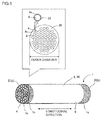
Fig. 1 is a diagram showing an embodiment of a monolith type separation membrane structure according to the present invention. -
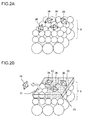
Fig. 2A is a schematic diagram showing the step of depositing seed crystals on a ceramic porous body. -
Fig. 2B is a schematic diagram showing the step of forming a zeolite separation membrane. -
Fig. 2C is a schematic diagram showing the step of forming a repair portion. -
Fig. 3 is a schematic diagram showing a state in which seeding slurry is poured in the step of depositing particles or showing a state in which a repairing material is poured in the repairing step. -
Fig. 4 is a schematic diagram showing an embodiment of a membrane forming step for forming a zeolite separation membrane on a porous body by hydrothermal synthesis. -
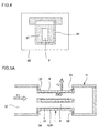
Fig. 5A is a schematic diagram showing an embodiment in which a monolith type separation membrane structure is installed in a housing and showing a cross-section parallel to the direction in which the cells of a ceramic separation membrane structure extend. -
Fig. 5B is a schematic diagram showing another embodiment in which a monolith type separation membrane structure is installed in a housing and showing a cross-section parallel to the direction in which the cells of a ceramic separation membrane structure extend. -
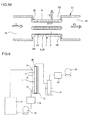
Fig. 6 is a schematic diagram showing the whole of a testing set used to perform a pervaporation test. - Hereinafter, embodiments of the present invention will be described with reference to the drawings. The embodiments described below are not intended to limit the present invention and may be changed, altered, or modified without departing from the scope of the present invention.
-
Fig. 1 shows an embodiment of a ceramicseparation membrane structure 1 according to the present invention.Figs. 2A to 2C show the step of forming azeolite separation membrane 33 and arepair portion 34 on a ceramicporous body 9.Fig. 2A shows the step of depositingseed crystals 36 on the ceramicporous body 9.Fig. 2B shows the step of forming thezeolite separation membrane 33.Fig. 2C shows the step of forming therepair portion 34. - The ceramic
separation membrane structure 1 of the present invention (also simply referred to as the separation membrane structure) includes a ceramic porous body 9 (also simply referred to as a porous body), a zeolite separation membrane 33 (also simply referred to as a separation membrane) disposed on the ceramicporous body 9, and arepair portion 34 made of a repairing material of organic-inorganic hybrid silica. The organic-inorganic hybrid silica is a combination of an organic component and a silicon-containing inorganic component. The two components may be in a blended state or chemically bonded together (the presence or absence of bonding, the degree of bonding, or the mode of bonding does not matter), having a domain size of 1 µm or less. - In the ceramic
separation membrane structure 1, therepair portion 34 made of a repairing material of organic-inorganic hybrid silica can improve the separation performance without reducing the permeability. The organic-inorganic hybrid silica, which has high resistance to hot water and alkali, is suitable for use in repairing membranes designed to be used for dehydration in an environment that can degrade silica and other materials and make them unusable. - As shown in
Fig. 1 , theporous body 9 has apartition wall 3 made of a porous material having a large number of pores. Thepartition wall 3forms cells 4, which serve as fluid flow channels. Theseparation membrane 33 and therepair portion 34 are formed on theinner wall surface 4s of thecells 4. - In the description, the ceramic
porous body 9 is also referred to as asubstrate 30. When two or more layers with different average particle sizes are formed on thesubstrate 30, the resulting stack including the layers is also referred to as aporous body 9. - As shown in
Fig. 2A ,seed crystals 36 are deposited in the process of forming theseparation membrane 33 on theinner wall surface 4s of thecells 4. As shown inFig. 2B , when theseparation membrane 33 is formed by hydrothermal synthesis, aseed crystal 36 fails to be deposited on thesubstrate 30 or drops off after the deposition, so that an uncovered defect occurs. In addition, a crack defect occurs in the membrane in the step of removing structure directing agent for zeolite by combustion. Thus, therepair portion 34 is formed after the formation of theseparation membrane 33. As shown inFig. 2C , therefore, the defect in thezeolite separation membrane 33, disposed on the ceramicporous body 9, is repaired by therepair portion 34. - Before the repairing, the
zeolite separation membrane 33 contains the structure directing agent. Therepair portion 34 may be formed before or after the removal of the structure directing agent. When the repairing is performed after the removal of the structure directing agent for zeolite, the crack defect generated in the step of removing the structure directing agent by combustion can also be repaired. - The mass ratio of the
repair portion 34 to thezeolite separation membrane 33 is preferably 1% or less. As used herein, the term "mass ratio" refers to the mass ratio determined by quantitative X-ray diffraction analysis. A standard material is prepared by mixing zeolite powders for thezeolite separation membrane 33 and therepair portion 34 in a specific mass ratio (e.g., separation membrane : repair portion = 9 : 1). The standard material is then subjected to X-ray diffraction analysis for the preparation of a calibration curve. Subsequently, the repairedzeolite separation membrane 33 is subjected to X-ray diffraction analysis, and the mass ratio of therepair portion 34 is determined by comparing the values of the resulting calibration curve with the values of the standard calibration curve. When the ratio of therepair portion 34 determined in this way is 1% or less, thezeolite separation membrane 33 can provide sufficient performance. Hereinafter, thesubstrate 30, theseparation membrane 33, therepair portion 34, and other features will be described in detail. - The
substrate 30 is preferably made of porous ceramic. More preferably, the aggregate particles for thesubstrate 30 are made of alumina (Al2O3), titania (TiO2), mullite (Al2O3·SiO2), potsherds (Scherben), cordierite (Mg2Al4Si5O18), or the like. Among them, alumina is further preferred because the raw material (aggregate particles) is easily available with controlled particle sizes and it can form a stable kneaded material and has high corrosion resistance. - The
substrate 30 has a round pillar outer shape with acircumference surface 6. Thesubstrate 30 may have any overall shape or size as long as it does not interfere with the separation function. The overall shape may be, for example, round pillar, square pillar (tubular with a tetragonal cross-section perpendicular to the central axis (longitudinal direction)), trigonal pillar (tubular with a triangular cross-section perpendicular to the central axis), or the like. In particular, a round pillar shape is preferred because of easiness of extrusion, resistance to deformation caused by firing, and easiness of sealing together with a housing. When the membrane is for use in hyperfiltration or ultrafiltration, the substrate preferably has a round pillar shape with a cross-sectional diameter of 30 to 220 mm perpendicular to the central axis and with a length of 150 to 2,000 mm in the central axis direction. Specifically, in an embodiment, thesubstrate 30 is monolith type (in the shape of a monolith) as shown inFig. 1 . The term "monolith type" refers to a honeycomb shape or a shape having a plurality of cells extending from a first end face to a second end face in the longitudinal direction. Alternatively, thesubstrate 30 may have a hollow cylindrical shape. - In the embodiment shown in
Fig. 1 , thesubstrate 30 has a plurality ofcells 4 that are formed from afirst end face 2a (one end face) to asecond end face 2b (the other end face) in the longitudinal direction and partitioned by theporous partition wall 3 to form fluid flow channels. Thesubstrate 30 has 30 to 2,500cells 4 passing through between both ends in the longitudinal direction and being parallel to the longitudinal direction. - In the
substrate 30, the cross-sectional shape of the cells 4 (the shape of the cross-section perpendicular to the direction in which thecells 4 extend) may be, for example, circular, elliptic, polygonal, or other shapes. The polygonal shape may be tetragonal, pentagonal, hexagonal, triangular or the like. When thesubstrate 30 has a round pillar shape, the direction in which thecells 4 extend coincides with the direction of the central axis (longitudinal direction). - When the
cells 4 of thesubstrate 30 have a circular cross-sectional shape, thecells 4 preferably have a diameter of 1 to 5 mm. The cells with a diameter of 1 mm or more can ensure a sufficient membrane area. When the diameter is 5 mm or less, the substrate can have a sufficient strength. - A plurality of layers with different average particle sizes may also be provided on the
substrate 30. Specifically, intermediate and surface layers with smaller average particle sizes may be stacked on thesubstrate 30. When the intermediate and surface layers are provided, the resulting stack including them is called theporous body 9. - Both end faces 2 and 2 of the
substrate 30 are preferably provided withseal portions 1s. Theseal portions 1s provided in this way can prevent part of a mixture from flowing directly into the interior of thesubstrate 30 from theend face 2 of thesubstrate 30 without passing through theseparation membrane 33, so that part of the mixture can be prevented from mixing with the gas or the like passing through theseparation membrane 33 and prevented from exiting with the gas or the like from thecircumference surface 6. Theseal portion 1s may be, for example, a glass seal or a metal seal. - The
separation membrane 33 has a plurality of pores with an average pore diameter smaller than that of the porous body 9 (thesubstrate 30 or the stack including the intermediate and surface layers). Theseparation membrane 33 is disposed on the surface of the inner wall of each cell 4 (inner wall surface 4s). Alternatively, theseparation membrane 33 may be disposed on the circumference surface of a hollowcylindrical substrate 30. - The average pore diameter of the
separation membrane 33 may be appropriately determined depending on the required filtration or separation performance (the particle size of substances to be removed). For example, a ceramic filter for use in hyperfiltration or ultrafiltration preferably has an average pore diameter of 0.01 to 1.0 µm. In this case, the average pore diameter of theseparation membrane 33 is the value measured by the air flow method described in ASTM F316. - Any of zeolites with various crystal structures, such as LTA, MFI, MOR, FER, FAU, DDR, CHA, and BEA may be used to form the
zeolite separation membrane 33. When made of DDR-type zeolite, theseparation membrane 33 can be specifically used as a gas separation membrane for selectively separating carbon dioxide or as a dehydration membrane for selectively separating water. - The
repair portion 34 is made of a repairing material of organic-inorganic hybrid silica to repair adefective portion 37 in which the surface of the ceramicporous body 9 is exposed without being covered with thezeolite separation membrane 33. - The organic-inorganic hybrid silica may be any of a material including organic and inorganic components chemically bonded together or a mixture of organic and inorganic components. The organic-inorganic hybrid silica to be used may be a product obtained by the hydrolysis and dehydration condensation of a silane coupling agent or an alkoxysilane. More specifically, the organic-inorganic hybrid silica to be used may be a product obtained by the hydrolysis and condensation of a bistriethoxysilyl compound of, for example, the structural formula: (C2H5O)3SiCnH2nSi(C2H5O)3 wherein n ≥ 1. In this material, an organic component and a silicon-containing inorganic component are chemically bonded together.
- Next, a method for producing the
separation membrane structure 1 using themonolith type substrate 30 will be described. First, a raw material for theporous body 9 is subjected to a forming process. For example, the raw material is subjected to extrusion using a vacuum extruder. This process results in a monolith typeunfired substrate 30 havingcells 4. Alternatively, a press molding process, a casting process, or the like may be appropriately selected and used. Theunfired substrate 30 is then fired, for example, at 900 to 1,450°C. - The
zeolite separation membrane 33 is then formed on theinner wall surface 4s of eachcell 4. Thezeolite separation membrane 33 used in the present invention can be synthesized by a conventionally known method. For example, as shown inFig. 4 , thezeolite separation membrane 33 is produced by a process that includes preparing a raw material solution (sol 67) of a silica source, an alumina source, a structure directing agent, an alkali source, water, and other materials; inserting theporous body 9 and the prepared raw material solution (sol 67) to a pressure-resistant vessel 65; and then subjecting the materials to a heat treatment (hydrothermal synthesis) at 100 to 200°C for 1 to 240 hours in adryer 68. - In this process,
zeolite seed crystals 36 are preferably applied to the porous body 9 (substrate 30) in advance (seeFig. 2A ).Fig. 3 shows an embodiment in which the seeding is performed by a flow-down method. Theseed crystals 36 can be deposited by a process that includes fixing theporous body 9 to the lower end of a wide-mouth funnel 62, pouring seedingslurry 64 from above theporous body 9 by opening acock 63, and allowing theslurry 64 to pass through thecells 4. - Subsequently, the
porous body 9 on which thezeolite separation membrane 33 is formed is washed with water or hot water at 80 to 100°C, then taken out, and dried at 80 to 100°C. Theporous body 9 is then placed in an electric furnace and heated at 400 to 800°C for 1 to 200 hours in the air atmosphere so that the structure directing agent in the pores of thezeolite separation membrane 33 is removed by combustion. Thezeolite separation membrane 33 can be formed in this way. - Examples of the silica source include colloidal silica, tetraethoxysilane, water glass, silicon alkoxide, fumed silica, precipitated silica, and the like.
- The structure directing agent is used to form the pore structure of zeolite. Examples of the structure directing agent include, but are not limited to, tetraethylammonium hydroxide, tetraethylammonium bromide, 1-adamantanamine, tetrapropylammonium hydroxide, tetrapropylammonium bromide, tetramethylammonium hydroxide, and other organic compounds.
- Examples of the alkali source include alkali metal sources such as sodium hydroxide, lithium hydroxide, and potassium hydroxide, alkaline earth metal sources such as magnesium hydroxide and calcium hydroxides, quaternary ammonium hydroxides, and the like.
- The method for producing the
zeolite separation membrane 33 may be applied to any of zeolites with various crystal structures such as LTA, MFI, MOR, FER, FAU, DDR, CHA, and BEA. - Next, a method for forming the
repair portion 34 to repair thezeolite separation membrane 33 will be described. As shown inFig. 2B , when theseparation membrane 33 is formed by hydrothermal synthesis, aseed crystal 36 fails to be deposited or drops off after the deposition, so that an uncovered defect occurs. - As shown in
Fig. 2C , therepair portion 34 is formed by a method for repairing the ceramic separation membrane structure of the present invention. A description will be given of a repairing step that includes forming the repair portion to repair thedefective portion 37 on the ceramic porous body. - First, organic-inorganic hybrid silica, which is obtained by subjecting a silane coupling agent or an alkoxysilane to hydrolysis and dehydration condensation or the like, is dispersed in a solvent such as an alcohol to form a sol (repairing material). The sol as a repairing material is deposited on the
defective portion 37 by a flow-down method in which the sol is allowed to flow down (by its own mass) along the surface of thezeolite separation membrane 33. Specifically, the sol is poured into the cylindrical holes (cells 23) of theporous body 9 so that a large amount of the liquid is allowed to flow parallel to the surface of the zeolite separation membrane. When allowed to pass through the cells 23 in this way, the sol flows on the surface of thezeolite separation membrane 33. - After the repairing material is deposited on the
defective portion 37, a heat treatment is preferably performed at a temperature lower than the temperature at which the template for thezeolite separation membrane 33 is fired. Specifically, after natural drying, heating in a reducing atmosphere at 350°C or lower, more preferably at 300 to 350°C is performed. - In the method for producing the ceramic separation membrane structure of the present invention, the sol obtained by dispersing organic-inorganic hybrid silica in a solvent such as ethanol is simply applied to the membrane by a flow-down method, naturally dried, and heated at 350°C or lower in a reducing atmosphere. Therefore, the method can be performed by a simple procedure with a simple apparatus. When repaired with the organic-inorganic hybrid silica, the membrane does not decrease in water permeability because the defective portion is selectively repaired. In addition, the organic-inorganic hybrid silica has high chemical resistance and can be treated at a temperature lower than the general zeolite template-firing temperature (the structure directing agent-firing temperature) in the repairing step, which does not degrade the performance of the zeolite separation membrane and is easy to perform.
- Next, a description will be given of a method for separating a component from a fluid as a mixture of two or more components using the
separation membrane structure 1 of this embodiment. As shown inFig. 5A , when theseparation membrane structure 1 of this embodiment is used to separate fluids, theseparation membrane structure 1 is preferably placed in atubular housing 51 having afluid inlet 52 and afluid outlet 53, in which fluid to be treated F1 is allowed to flow into thehousing 51 through thefluid inlet 52 and separated by theseparation membrane structure 1, and the separated fluid (treated fluid F2) is preferably discharged from thefluid outlet 53. - As shown in
Fig. 5A , when theseparation membrane structure 1 is placed in thehousing 51, sealingmembers separation membrane structure 1 and thehousing 51 at both ends of theseparation membrane structure 1. The sealingmembers 54 are typically, but not limited to, O-rings or the like. - The fluid to be treated F1, which flow into the
housing 51 through thefluid inlet 52, entirely flows into thecells 4 of theseparation membrane structure 1. From the fluid to be treated F1 flowing in thecells 4, the treated fluid F2 is separated by being allowed to pass through theseparation membrane 33. The treated fluid F2 then enters thesubstrate 30. Subsequently, the treated fluid F2 flows out of thesubstrate 30 through thecircumference surface 6 of thesubstrate 30 and exits from thefluid outlet 53 to the outside (outer space). The sealingmembers -
Fig. 5B shows another embodiment in which theseparation membrane structure 1 is installed in ahousing 51. As shown inFig. 5B , theseparation membrane structure 1 is placed in atubular housing 51 having afluid inlet 52 andfluid outlets housing 51 through itsfluid inlet 52 and then separated by theseparation membrane structure 1, the separated fluid (treated fluid F2) is discharged from thefluid outlet 53, and the reminder (fluid F3) is discharged from thefluid outlet 58. The discharge of the fluid F3 from thefluid outlet 58 makes it possible to increase the flow rate of the fluid to be treated F1 during the operation and to increase the flow rate of the permeating treated fluid F2. - Hereinafter, the present invention will be more specifically described with reference to examples, which, however, are not intended to limit the present invention.
- A
monolith type substrate 30 was prepared, and aseparation membrane 33 was formed in thecells 4 of thesubstrate 30. First, the preparation of thesubstrate 30 will described. - A kneaded material was prepared by adding water, a dispersing agent, and a thickener to alumina particles (aggregate particles) having an average particle size of 50 µm, and by mixing and kneading them. The resulting kneaded material was extruded to form a honeycomb-shaped
unfired substrate 30. - The
substrate 30 was then fired at 900 to 1,500°C. The substrate 30 (porous body 9) had a round pillar outer shape, an outer diameter of 30 mm, a cell diameter of 2.2 mm, 61 cells, and a length of 160 mm. - A DDR membrane was formed as a
separation membrane 33 on theinner wall surface 4s of eachcell 4 of theporous body 9. - DDR-type zeolite crystal powder was produced based on the DDR-type zeolite producing method described in M. J. den Exter, J. C. Jansen, H. van Bekkum, Studies in Surface Science and Catalysis vol. 84, Ed. by J. Weitkamp et al., Elsevier (1994) 1159-1166 or
JP-A-2004-083375 seed crystals 36, or if necessary, the DDR-type zeolite crystal powder was ground and then used asseed crystals 36. A seed crystal dispersion was prepared by dispersing theseed crystals 36 in water after the synthesis or the grinding and then removing coarse particles. - The seed crystal dispersion prepared in the step (2-1) was diluted with ethanol so that the DDR concentration reached 0.3% by mass (the concentration of the solid in the slurry 64). The dilution was stirred with a stirrer at 300 rpm to give a seeding slurry (slurry 64). The
porous body 9 was fixed to the lower end of a wide-mouth funnel 62, 160 ml of the seeding slurry was poured from above theporous body 9 and allowed to pass through the cells (seeFig. 3 ). The interior of the cells of theporous body 9, in which theslurry 64 was allowed to flow down, was subjected to through air drying under the conditions of room temperature and an air velocity of 3 to 6 m/s for 10 minutes. A sample was obtained after allowing theslurry 64 to flow down and through air drying, which were repeated twice. After the drying, the sample was subjected to microstructure observation with an electron microscope. It was confirmed that the DDR particles were deposited on the surface of theporous body 9. - After 7.35 g of ethylenediamine (manufactured by Wako Pure Chemical Industries, Ltd.) was added to a 100 ml wide-mouth fluororesin bottle, 1.156 g of 1-adamantanamine (manufactured by Sigma-Aldrich) was added to the bottle and so dissolved that no 1-adamantanamine precipitate remained. To another vessel were added 98.0 g of 30% by mass colloidal silica (trade name: SNOWTEX S, manufactured by Nissan Chemical Industries, Ltd.) and 116.55 g of ion exchanged water, and gently stirred. Subsequently, the mixture was added to the wide-mouth bottle containing the mixture of ethylenediamine and 1-adamantanamine. The materials were then mixed by being shaken strongly to form a raw material solution. The molar ratio between the components in the raw material solution was as follows: 1-adamantanamine/SiO2 = 0.016, water/SiO2 = 21. The raw material solution in the wide-mouth bottle was then stirred for 1 hour with a homogenizer on which the bottle was set. The
porous body 9 with the DDR particles deposited in the step (2-2) was placed in a pressure-resistantstainless steel vessel 65 equipped with a fluororesin inner cylinder with an inner volume of 300 ml. The prepared raw material solution (sol 67) was added to thevessel 65 and then subjected to a heat treatment (hydrothermal synthesis) at 138°C for 15 hours (seeFig. 4 ). During the hydrothermal synthesis, the solution was alkaline because of colloidal silica and ethylenediamine as raw materials. - The membrane formed in the membrane forming step was heated in the air atmosphere at 450°C for 50 hours using an electric furnace, so that 1-adamantanamine in the pores was removed by combustion. As a result of X-ray diffraction analysis, the crystal phase was identified, and the presence of DDR-type zeolite was confirmed. After the membrane production, it was also confirmed that the
porous body 9 was covered with DDR-type zeolite. - The zeolite separation membrane formed as described above was repaired using organic-inorganic hybrid silica. Hereinafter, the repair will be described more specifically.
- While the temperature was kept at 3°C, 17.01 g of BTESM (a bistriethoxysilyl compound of the structural formula: (C2H5O)3SiCnH2nSi(C2H5O)3 (n ≥ 1) manufactured by Gelest, Inc.) and 44.28 g of ethanol were mixed and stirred (A). To 4.54 g of water was added 0.84 g of nitric acid (B). The mixture (B) was added dropwise to the mixture (A), and the resulting mixture was stirred at 60°C for 5 hours (C). A repairing material was obtained by adding ethanol to the mixture (C) in such a manner that a solid content of 0.1% by mass was reached (D).
- Using a flow-down method, 160 cc of the repairing material (D) was applied to the surface of the DDR membrane in the monolith type ceramic separation membrane structure 1 (unrepaired) with a diameter of 30 mm and a length of 160 mm. The inside of the cells was then blown off with a blower. The structure was then naturally dried in the air atmosphere for 1 hour. The dried structure was fired at 350°C for 2 hours in an N2 atmosphere to give a ceramic
separation membrane structure 1 containingrepair portion 34. - The prepared membrane was evaluated for performance of dehydration of acetic acid by a pervaporation method (PV method).
Fig. 6 is a schematic diagram showing the whole of a testing set used to perform the pervaporation test. Amodule 75 made of SUS has a structure in which theseparation membrane structure 1 having thezeolite separation membrane 33 is installed in a cylindrical outer vessel made of SUS. In theSUS module 75, the interior space is partitioned by thezeolite separation membrane 33 into a raw material-side space 76 and a permeation-side space 77. Afeed solution inlet 73 and afeed solution outlet 74 are formed to communicate with the raw material-side space 76. A permeatingvapor collection port 80 for discharging permeating vapor to the outside is formed at the upper end of the permeation-side space 77. - A raw material (feed solution) containing 90% by mass of acetic acid was placed in a
raw material tank 71 and heated at 90°C. Using afeed pump 72, the raw material was circulated by feeding the raw material to the raw material-side space 76 of the SUS (stainless steel)module 75 through thefeed solution inlet 73 and returning the raw material discharged from thefeed solution outlet 74 to theraw material tank 71. Aflowmeter 79 was used to monitor the flow rate of the raw material. - Using a
vacuum pump 83, the pressure at the support side (permeation-side space 77) of thezeolite separation membrane 33 was reduced to 100 torr so that permeating vapor was allowed to pass through thezeolite separation membrane 33 and discharged from the permeatingvapor collection port 80 was collected into a liquid N2 trap 81. The degree of vacuum in the permeation-side space 77 was controlled by apressure regulator 82. - The mass of the resulting liquid was determined with an electronic balance, and the composition of the liquid was analyzed by neutralization titration.
- In the pervaporation test, the amount of the permeate and the acetic acid concentration were measured and the water flux and the acetic acid flux were calculated.
-
[Table 1] Acetic Acid Flux kg/m2h Water Flux kg/m2h Before Repair 0.0050 1.3 After Repair 0.0027 1.3 - As shown in Table 1, the repair reduced only the acetic acid flux without reducing the water flux. In other words, the repair reduced the amount of leakage of acetic acid through defects to increase the separation factor, without changing the amount of permeation of water.
- The BTESM used in the examples is a material including two components, an organic component and a silicon-containing inorganic component, chemically bonded together. Other types of organic-inorganic hybrid silica including two components, an organic component and a silicon-containing inorganic component, chemically bonded together can also be expected to produce a similar effect.
- The method for producing the ceramic separation membrane structure of the present invention can be used to repair a ceramic separation membrane structure having a zeolite separation membrane formed on the inner wall surface of cells. The ceramic separation membrane of the present invention can be used to separation of a gas mixture or a liquid mixture.
- 1: separation membrane structure, 1s: seal portion, 2, 2a, 2b: end face, 3: partition wall, 4: cell, 4s: inner wall surface, 6: circumference surface, 9: porous body, 30: substrate, 33: separation membrane, 34: zeolite repair portion, 36: seed crystal, 37: defective portion, 51: housing, 52: fluid inlet, 53, 58: fluid outlet, 54: sealing member, 62: wide-mouth funnel, 63: cock, 64: slurry, 65: pressure-resistant vessel, 67: sol, 68: dryer, 71: raw material tank, 72: feed pump, 73: feed solution inlet, 74: feed solution outlet, 75: SUS module, 76: raw material-side space, 77: permeation-side space, 79: flowmeter, 80: permeating vapor collection port, 81: liquid N2 trap, 82: pressure regulator, 83: vacuum pump.
Claims (8)
- A ceramic separation membrane structure comprising:a ceramic porous body;a zeolite separation membrane disposed on the ceramic porous body; anda repair portion made of a repairing material of organic-inorganic hybrid silica.
- The ceramic separation membrane structure according to claim 1, wherein the organic-inorganic hybrid silica is a product obtained by hydrolysis and dehydration condensation of a silane coupling agent or an alkoxysilane.
- The ceramic separation membrane structure according to claim 1 or 2,
wherein the organic-inorganic hybrid silica is a product obtained by hydrolysis and condensation of a bistriethoxysilyl compound of the structural formula:
(C2H5O)3SiCnH2nSi(C2H5O)3, wherein n ≥ 1.
- The ceramic separation membrane structure according to any one of claims 1 to 3, wherein the zeolite separation membrane comprises DDR-type zeolite.
- The ceramic separation membrane structure according to any one of claims 1 to 4, wherein the ceramic porous body has a monolith shape.
- A method for producing the ceramic separation membrane structure according to any one of claims 1 to 5,
the method comprising a repairing step to form the repair portion, wherein
the repairing step comprises depositing the repairing material by a flow-down method comprising allowing the repairing material to flow down along a surface of the zeolite separation membrane. - The method for producing ceramic separation membrane structure according to claim 6, wherein the repairing step comprises performing a heat treatment at a temperature lower than a template firing temperature of zeolite membrane after the repairing material is deposited.
- The method for producing ceramic separation membrane structure according to claim 7, wherein the heat treatment is performed at a temperature of 350°C or lower.
Applications Claiming Priority (2)
| Application Number | Priority Date | Filing Date | Title |
|---|---|---|---|
| JP2013070731 | 2013-03-28 | ||
| PCT/JP2014/056125 WO2014156579A1 (en) | 2013-03-28 | 2014-03-10 | Ceramic separation membrane structure and method for producing same |
Publications (2)
| Publication Number | Publication Date |
|---|---|
| EP2979747A1 true EP2979747A1 (en) | 2016-02-03 |
| EP2979747A4 EP2979747A4 (en) | 2016-11-30 |
Family
ID=51623564
Family Applications (1)
| Application Number | Title | Priority Date | Filing Date |
|---|---|---|---|
| EP14774431.2A Withdrawn EP2979747A4 (en) | 2013-03-28 | 2014-03-10 | Ceramic separation membrane structure and method for producing same |
Country Status (5)
| Country | Link |
|---|---|
| US (1) | US9968891B2 (en) |
| EP (1) | EP2979747A4 (en) |
| JP (1) | JPWO2014156579A1 (en) |
| CN (1) | CN105073236B (en) |
| WO (1) | WO2014156579A1 (en) |
Families Citing this family (6)
| Publication number | Priority date | Publication date | Assignee | Title |
|---|---|---|---|---|
| JP2016175063A (en) * | 2015-03-20 | 2016-10-06 | 日本碍子株式会社 | Regeneration method of membrane |
| JP6685998B2 (en) * | 2015-03-31 | 2020-04-22 | 日本碍子株式会社 | Zeolite membrane structure |
| CN108290123B (en) | 2015-11-18 | 2021-03-26 | 日本碍子株式会社 | Method for repairing separation membrane and method for manufacturing separation membrane structure |
| JP2019511958A (en) * | 2016-02-02 | 2019-05-09 | ユニヴァーシティ オブ ワシントン | Ceramic selective membrane |
| CN110719808B (en) * | 2017-06-07 | 2021-12-28 | 日本碍子株式会社 | Dewatering method and dewatering device |
| CN111804153A (en) * | 2020-06-01 | 2020-10-23 | 武汉科技大学 | Preparation method of T-type molecular sieve and BTESE composite membrane |
Family Cites Families (14)
| Publication number | Priority date | Publication date | Assignee | Title |
|---|---|---|---|---|
| US5968366A (en) * | 1994-07-08 | 1999-10-19 | Exxon Research And Engineering Company | Zeolite containing composition with a selectivity enhancing coating |
| GB9607090D0 (en) * | 1996-04-03 | 1996-06-05 | Bratton Graham J | Improved membrane |
| US6536604B1 (en) * | 1999-06-25 | 2003-03-25 | C. Jeffrey Brinker | Inorganic dual-layer microporous supported membranes |
| JP2002263457A (en) * | 2001-03-08 | 2002-09-17 | Toray Ind Inc | Method for treating zeolite film and separation method |
| JP2003290636A (en) * | 2002-04-03 | 2003-10-14 | Ngk Insulators Ltd | Defect restoring method of membrane formed on porous substrate, membrane separating body and gas separating body with defect of membrane restored |
| JP4355478B2 (en) | 2002-08-29 | 2009-11-04 | 日本碍子株式会社 | Method for producing DDR type zeolite |
| JP2004214089A (en) | 2003-01-07 | 2004-07-29 | Toyota Motor Corp | Thin film defect detecting method, thin film defect repairing method using the same, and device therefor |
| CA2636322C (en) | 2006-01-16 | 2015-02-24 | Stichting Energieonderzoek Centrum Nederland | Microporous organic-inorganic hybrid silica separation membrane |
| US7923060B2 (en) * | 2006-10-18 | 2011-04-12 | Ngk Insulators, Ltd. | Method of manufacturing ceramic filter |
| JP2009233540A (en) * | 2008-03-26 | 2009-10-15 | Hiroshima Univ | Separation membrane and manufacturing method of separation membrane |
| JP2009255035A (en) | 2008-03-26 | 2009-11-05 | Ngk Insulators Ltd | Ceramic filter |
| JP2010115610A (en) * | 2008-11-14 | 2010-05-27 | Sumitomo Electric Ind Ltd | Zeolite composite separation membrane and method for manufacturing the same |
| JP2010158665A (en) * | 2008-12-10 | 2010-07-22 | Ngk Insulators Ltd | Method for producing ddr type zeolite membrane-containing body |
| MY183844A (en) * | 2010-02-25 | 2021-03-17 | Ngk Insulators Ltd | Zeolite film and process for producing zeolite film |
-
2014
- 2014-03-10 EP EP14774431.2A patent/EP2979747A4/en not_active Withdrawn
- 2014-03-10 WO PCT/JP2014/056125 patent/WO2014156579A1/en active Application Filing
- 2014-03-10 JP JP2015508244A patent/JPWO2014156579A1/en active Pending
- 2014-03-10 CN CN201480019001.9A patent/CN105073236B/en not_active Expired - Fee Related
-
2015
- 2015-09-28 US US14/867,110 patent/US9968891B2/en active Active
Also Published As
| Publication number | Publication date |
|---|---|
| US20160016125A1 (en) | 2016-01-21 |
| CN105073236A (en) | 2015-11-18 |
| WO2014156579A1 (en) | 2014-10-02 |
| US9968891B2 (en) | 2018-05-15 |
| CN105073236B (en) | 2017-09-22 |
| EP2979747A4 (en) | 2016-11-30 |
| JPWO2014156579A1 (en) | 2017-02-16 |
Similar Documents
| Publication | Publication Date | Title |
|---|---|---|
| US9782729B2 (en) | Ceramic separation membrane structure, and repair method thereof | |
| US9968891B2 (en) | Ceramic separation membrane structure and method for producing same | |
| US11278848B2 (en) | Honeycomb shaped porous ceramic body, manufacturing method for same, and honeycomb shaped ceramic separation membrane structure | |
| US9205417B2 (en) | Zeolite membrane regeneration method | |
| EP2832429B1 (en) | Honeycomb shaped porous ceramic body, manufacturing method for same, and honeycomb shaped ceramic separation membrane structure | |
| JP6670764B2 (en) | Separation membrane structure | |
| JP2020028881A (en) | Separation membrane structure and gas separating method | |
| EP2902093B1 (en) | Defect detection method for monolithic separation membrane structures and repair method | |
| US10258933B2 (en) | Zeolite membrane having oxygen eight-membered rings, method for manufacturing zeolite membrane and method for evaluating zeolite membrane having oxygen eight-membered rings | |
| EP2832430B1 (en) | Honeycomb shaped porous ceramic body, manufacturing method for same, and honeycomb shaped ceramic separation membrane structure | |
| EP2540384A1 (en) | Zeolite film and process for producing zeolite film | |
| CN108290123B (en) | Method for repairing separation membrane and method for manufacturing separation membrane structure |
Legal Events
| Date | Code | Title | Description |
|---|---|---|---|
| PUAI | Public reference made under article 153(3) epc to a published international application that has entered the european phase |
Free format text: ORIGINAL CODE: 0009012 |
|
| 17P | Request for examination filed |
Effective date: 20151009 |
|
| AK | Designated contracting states |
Kind code of ref document: A1 Designated state(s): AL AT BE BG CH CY CZ DE DK EE ES FI FR GB GR HR HU IE IS IT LI LT LU LV MC MK MT NL NO PL PT RO RS SE SI SK SM TR |
|
| AX | Request for extension of the european patent |
Extension state: BA ME |
|
| DAX | Request for extension of the european patent (deleted) | ||
| A4 | Supplementary search report drawn up and despatched |
Effective date: 20161103 |
|
| RIC1 | Information provided on ipc code assigned before grant |
Ipc: B01D 69/12 20060101ALI20161025BHEP Ipc: B01D 69/04 20060101ALI20161025BHEP Ipc: B01D 71/02 20060101AFI20161025BHEP Ipc: B01D 69/10 20060101ALI20161025BHEP Ipc: B01D 65/10 20060101ALI20161025BHEP |
|
| 17Q | First examination report despatched |
Effective date: 20171002 |
|
| STAA | Information on the status of an ep patent application or granted ep patent |
Free format text: STATUS: EXAMINATION IS IN PROGRESS |
|
| STAA | Information on the status of an ep patent application or granted ep patent |
Free format text: STATUS: THE APPLICATION IS DEEMED TO BE WITHDRAWN |
|
| 18D | Application deemed to be withdrawn |
Effective date: 20181011 |