EP2979397B1 - System and method for a control plane reference model framework - Google Patents
System and method for a control plane reference model framework Download PDFInfo
- Publication number
- EP2979397B1 EP2979397B1 EP14783405.5A EP14783405A EP2979397B1 EP 2979397 B1 EP2979397 B1 EP 2979397B1 EP 14783405 A EP14783405 A EP 14783405A EP 2979397 B1 EP2979397 B1 EP 2979397B1
- Authority
- EP
- European Patent Office
- Prior art keywords
- network
- component
- data plane
- nodes
- control
- Prior art date
- Legal status (The legal status is an assumption and is not a legal conclusion. Google has not performed a legal analysis and makes no representation as to the accuracy of the status listed.)
- Active
Links
- 238000000034 method Methods 0.000 title claims description 38
- 230000008569 process Effects 0.000 claims description 17
- 238000012545 processing Methods 0.000 claims description 16
- 230000006978 adaptation Effects 0.000 claims description 12
- 238000004891 communication Methods 0.000 claims description 11
- 238000003860 storage Methods 0.000 claims description 11
- 238000013507 mapping Methods 0.000 claims description 7
- 238000007726 management method Methods 0.000 claims description 5
- 230000006855 networking Effects 0.000 claims description 5
- 230000005540 biological transmission Effects 0.000 claims description 4
- 238000001914 filtration Methods 0.000 claims description 2
- 238000001228 spectrum Methods 0.000 claims description 2
- 230000002776 aggregation Effects 0.000 claims 1
- 238000004220 aggregation Methods 0.000 claims 1
- 230000008859 change Effects 0.000 description 9
- 230000015654 memory Effects 0.000 description 9
- 230000006870 function Effects 0.000 description 3
- 230000009897 systematic effect Effects 0.000 description 3
- 230000006835 compression Effects 0.000 description 2
- 238000007906 compression Methods 0.000 description 2
- 238000013461 design Methods 0.000 description 2
- 238000010586 diagram Methods 0.000 description 2
- 230000006399 behavior Effects 0.000 description 1
- 238000013500 data storage Methods 0.000 description 1
- 230000001419 dependent effect Effects 0.000 description 1
- 238000011161 development Methods 0.000 description 1
- 239000004744 fabric Substances 0.000 description 1
- 230000010354 integration Effects 0.000 description 1
- 230000014759 maintenance of location Effects 0.000 description 1
- 230000007246 mechanism Effects 0.000 description 1
- 230000004048 modification Effects 0.000 description 1
- 238000012986 modification Methods 0.000 description 1
- 230000003287 optical effect Effects 0.000 description 1
- 230000002093 peripheral effect Effects 0.000 description 1
- 238000011084 recovery Methods 0.000 description 1
- 239000007787 solid Substances 0.000 description 1
- 230000003068 static effect Effects 0.000 description 1
- 230000001360 synchronised effect Effects 0.000 description 1
Images


Classifications
-
- H—ELECTRICITY
- H04—ELECTRIC COMMUNICATION TECHNIQUE
- H04L—TRANSMISSION OF DIGITAL INFORMATION, e.g. TELEGRAPHIC COMMUNICATION
- H04L45/00—Routing or path finding of packets in data switching networks
- H04L45/42—Centralised routing
-
- H—ELECTRICITY
- H04—ELECTRIC COMMUNICATION TECHNIQUE
- H04L—TRANSMISSION OF DIGITAL INFORMATION, e.g. TELEGRAPHIC COMMUNICATION
- H04L41/00—Arrangements for maintenance, administration or management of data switching networks, e.g. of packet switching networks
- H04L41/12—Discovery or management of network topologies
- H04L41/122—Discovery or management of network topologies of virtualised topologies, e.g. software-defined networks [SDN] or network function virtualisation [NFV]
-
- H—ELECTRICITY
- H04—ELECTRIC COMMUNICATION TECHNIQUE
- H04L—TRANSMISSION OF DIGITAL INFORMATION, e.g. TELEGRAPHIC COMMUNICATION
- H04L45/00—Routing or path finding of packets in data switching networks
- H04L45/302—Route determination based on requested QoS
-
- H—ELECTRICITY
- H04—ELECTRIC COMMUNICATION TECHNIQUE
- H04W—WIRELESS COMMUNICATION NETWORKS
- H04W28/00—Network traffic management; Network resource management
- H04W28/02—Traffic management, e.g. flow control or congestion control
- H04W28/0231—Traffic management, e.g. flow control or congestion control based on communication conditions
-
- H—ELECTRICITY
- H04—ELECTRIC COMMUNICATION TECHNIQUE
- H04L—TRANSMISSION OF DIGITAL INFORMATION, e.g. TELEGRAPHIC COMMUNICATION
- H04L45/00—Routing or path finding of packets in data switching networks
- H04L45/64—Routing or path finding of packets in data switching networks using an overlay routing layer
Definitions
- the present invention relates to the field of network communications, and, in particular embodiments, to a method and a corresponding network component for a control plane reference model framework.
- SDN Software-defined networking
- RAN radio access networks
- the SDN in RAN generally manages routing and traffic engineering (TE) to provide a forwarding path and required bandwidth or rate for traffic flow over each link over the path (multiple routes are also possible).
- the SDN in RAN also manages radio coordination to provide on-demand configuration of radio node specification, including the access link/backhaul link and the carrier.
- the on-demand configuration may include selecting built-in components with different specifications.
- the on-demand configuration can also include coordinating the mapping/allocation of the 5-tuple wireless resource (time/frequency/code/ power/spatial) to active flows.
- control plane such as in term of SDN framework, becomes challenging. There is a need for an improved control plane reference model and architecture for such networks including radio nodes and other nodes.
- Open Flow Switch Specification Version 1.3.1 published by Open Flow Networking Foundation provides a basic framework and protocol for implementing a network switch based on OpenFlow protocol.
- US 20110131252 relates to method and apparatus for physical/logical relationship mapping between resources.
- the present disclosure provides a method according to claim 1 and a network component according to claim 15. Further technical features are defined in the respective dependent claims.
- embodiments are provided herein to present a framework for a control plane reference model for such types of networks.
- the embodiments include identifying key control functionality of the control plane, and providing a control plane architecture to enable the control functionality of multiple control components. Additionally, interface between the control components are provided.
- Various workflows among the control components are also provided for exemplary scenarios.
- SDT Software-defined networking
- VN virtual network
- a service can be any network service provided by network resources, such as a data service, a voice service, a video service, other network based services, or combinations thereof.
- SDP software defined data plane protocol
- SDT and SDP components are also included.
- the embodiments also include identifying radio node functionality for improved or future wireless networks, and interface between the remote control plane and such radio nodes (e.g., at the data plane).
- This framework of reference model and interface design can be used in the systematic design, development of algorithms, and control mechanisms of future wireless or integrated network architecture.
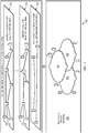
- Figure 1 illustrates using multiple co-existing customized virtual networks 100 that can be implemented using the control plane functionality herein and further using integrated physical network resources 120.
- the integrated physical network resources may include multiple domains or sub-networks 150.
- the co-existing customized virtual networks 100 achieved using the control plane functionality can be configured according to various logical architectures, including for example an arbitrary architecture such as for content delivery, a hierarchical star architecture such as for machine-to-machine (M2M) communications, and a flat data plane architecture such as for between end customers.
- M2M machine-to-machine
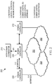
- FIG. 2 shows an embodiment of a control plane architecture 200 that enables a configurable data plane architecture, such as the configurable data plane architecture 100, and allows the functioning and operation of the various configured VNs 102 at the data plane.
- the control plane architecture 200 is a logical control architecture that has a hierarchical structure to handle multiple geographic domains 250, which may be networks, sub-networks, or other types of network domains.
- a plurality of domain controllers 220 assigned to the different domains 250 are each configured with three control elements, including a software defined topology (SDT) component, a software defined network (SDN) component, and a software defined protocol (SDP) component.
- SDT software defined topology
- SDN software defined network
- SDP software defined protocol
- the physical implementation of the control functionality of the components can be implemented by a network entity or location (e.g., the domain controllers 220 corresponds to a node or data center), or alternatively can be virtual cloud based (e.g., in a distributed manner across a network or virtual network referred which is referred to as a cloud).
- the SDT component provides on-demand, configurable and customized logical data plane architecture.
- the SDN component provides on-demand customized resource management to meet the requirement of the defined data plane architecture.
- the SDP component provides on-demand, configurable and customized data plane process protocol that may be both radio related and non-radio related.
- the size of the domain 250 for each individual domain controller 220 can be different and can be dynamically configured.
- an inter-domain coordinator 210 can be used to coordinate inter-domain control functionality between the different domain controllers 220.
- Each domain controller 220 can communicate with the inter-domain coordinator 210 via a first interface (e.g., via API), referred to in Figure 2 as a domain control-to-orchestrator (C-O) interface.
- the domain controller 220 can communicate with another domain controller 220 via a second interface, referred to in Figure 2 as a domain control-to-domain control (C-C) interface.
- the domain controller 220 also communicates with its respective domain via a third interface, referred to in Figure 2 as a domain control-to-physical network (C-P) interface (or control plane-to-data plane (C-D) interface.
- C-P domain control-to-physical network
- C-D control plane-to-data plane
- the network nodes belong to a first layer, e.g., at the various domains 250, and are abstracted (or grouped) into virtual nodes at a second layer.
- the second layer comprises virtual nodes each being a group of multiple physical nodes at the first layer.
- the virtual nodes at the second layer are treated by the SDT/SDN/SDP components, e.g., in the domain controllers 220, as individual nodes having corresponding input and output parameters for control and configuration.
- the network nodes at the first layer which form the virtual nodes, can be transparent to the SDT/SDN/SDP components. Multiple abstraction levels may be used to group nodes into higher abstraction layer nodes.
- the network nodes at the physical network layer may be grouped into virtual nodes at a first abstraction layer.
- the virtual nodes at the first abstraction layer may further be grouped into virtual nodes at a second abstraction layer, which may then be treated by the SDT/SDN/SDP components as individual nodes.
- This network layer abstraction simplifies handling and managing a large number of nodes in multiple networks or domains by the SDT/SDN/SDP components.
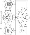
- FIG 3 shows an embodiment of control components 300 within a domain controller 310.
- the control components 300 include a SDT component 311, a SDN component 312, and a SDP element 313 with respective control functionalities, as described above.
- the control components of the domain controller 310 provide the control functionality to the corresponding domain 320.
- the integrated physical network 320 may include or the corresponding domain may be a wireless network including radio nodes.
- the domain controller 310 may be managed or operated by an operator to handle, on-demand, communication and information delivery for a service or a VN.
- the domain controller 310 receives input via API (application programming interface) from an application/service/VN operator to obtain service requirement (e.g., service logical topology, quality of service, preferred cost).
- API application programming interface
- the domain controller 310 also receives input information from the integrated physical network 320, including network status analysis information, infrastructure abstraction information, mobility track information (e.g., for mobile users), and/or quality of service (QoS) analysis information.
- the control elements at the domain controller 310 processes such information to provide a customized data plane for handling communications and data forwarding for a service or VN, by resource management such as path/bandwidth or rate allocation to meet the requirement of the defined data plane, and the data plane process protocol for forwarding/processing of associated traffic.
- the decisions from the control elements at the domain controller 310 are sent to the data plane (the network nodes) via the interface between control plane and data plane (I-CD).
- the interface between the applications/service/virtual network operator and control plane includes information, such as, service logical topology, application/traffic characteristics, end-customer mobility distribution, required service QoS, and/or other relevant information for enabling an applications/service/virtual network.
- the interface (I-Mob) between Mobility management/track and control plane includes information such as current location of end-customers, e.g., geographic location, location relative to network, and possible prediction of location.
- the interface (I-QoE) between control plane and Delivered QoE analysis includes QoE analysis information such as based on QoE information (e.g., rate, packet loss rate, black screen time).
- the interface (I-DC-QoE) between data plane and control plane includes the QoE information.
- the interface (I-abs) between control plane and infrastructure abstraction includes information such as effective spectra efficiency of mobile terminals.
- the interface (I-NS) between control pane and network status analysis includes information such as network load.
- the interface (I-DC-NS) between data plane and control plane includes information such as node load and packet drop rates.
- the interface (I-CD) includes information such as routing information, data process functionality, and work flow.
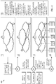
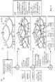
- FIG 4 shows an embodiment working flow 400 for handling content/information transmission between end-to-end customers.
- the working flow 400 is an exemplary scheme implemented by the control elements (SDT, SDN, and SDP), e.g., using the control plane architecture 200, to configure the virtual network for forwarding/processing/handling traffic between end-to-end customers.
- the SDT component determines the logical data plane topology architecture and source/destination locations based on factors, such as service/connectivity requirements, available network resource, QoS requirement, and/or other factors. As part of determining the logical topology for the data plane, the SDT component selects network elements or nodes and required service quality necessary to implement or enable the data plane (for a service or VN).
- the selected elements may be at least a source location/node and a destination location/node for handling content/information transmission between end-to-end customers/devices.
- the SDT also uses mobility tracking, network status, and quality of experience (QoE) information. The SDT provides the decision to the SDN component.
- QoE quality of experience
- the SDN component maps the logical topology (from the SDT component) to a physical network resource. This process includes allocating network resources (e.g., one or more paths or routes, bandwidth) to meet the required data plane architecture and QoS requirement.
- the SDN component operation may involve multiple-handshake and negotiation between the control components and/or the inter-domain controllers.
- the SDN component operations may also use physical infrastructure abstraction information.
- the SDP component defines the data plane process functionality, e.g., as part of a data plane protocol, for each involved network node assigned by the SDN component, including radio nodes for wireless networks if considered.
- the control components interface with each other and negotiate for the best solution, for example to satisfy QoS with the minimum network resource used and/or maximize the operator/customer revenue. Additional on-going adaptation may also follow.
- the SDT component may need to reconfigure the logical data plane architecture to adapt to dynamic changes such as change in required end-to-end service/flow rate due to source rate adaptation to handle network congestion or receiver behavior at the nodes/end user's equipment, change in service/flow rate in some links on the forwarding path caused by compression due to link congestion, or change of source or destination location due to node/user mobility.
- the SDN needs to adapt to the modification of logical data plane topology to remap logical connectivity to physical network resource, and for reconfiguring (by the SDP component) the data plane protocol.
- the SDT, SDN, and SDP iteratively or continuously implement their corresponding control functionality, thus adjusting dynamically to changes that may occur for a service or virtual network.
- This provides dynamic change to the data plane topology and necessary remapping into adjusted network resources according to the changes.
- FIG. 5 shows an embodiment working flow 500 for handling machine-to-machine (M2M) communications.
- the working flow 500 is an exemplary scheme implemented by the control elements (SDT, SDN, and SDP), e.g., as in domain controller 310, to configure the data plane for forwarding and handling traffic for M2M communications, e.g., between machines such as sensors or meters absent of direct user involvement.
- the SDT component determines the logical data plane topology architecture, e.g., for a first VN, based on factors such as traffic characteristics and end-devices distribution, connectivity/QoS requirements, available network resource, and/or other factors.
- the SDT may also use mobility tracking, network status, and QoE information.
- the SDT provides the decision to the SDN component.
- the SDN component maps the logical topology (from the SDT component) to a physical network resource. This process includes allocating network resources (e.g., one or more paths or routes, bandwidth) to meet the required data plane architecture and QoS requirement.
- the SDN component operation may involve multiple-handshake and negotiation between the control components and/or the inter-domain controllers.
- the SDN component operations may also use physical infrastructure abstraction information.
- the SDP component defines the data plane process functionality, e.g., as part of a data plane protocol, for each involved network node assigned by the SDN component, including radio nodes for wireless networks if considered.
- control components interface with each other and negotiate for the best solution, for example to satisfy QoS with the minimum network resource used and/or maximize the operator/customer revenue. Additional on-going adaptation may also follow, such as logical topology changes (by the SDT component) due to traffic distribution (e.g., mobility) change and network status change, remapping (by the SDN component) the logical topology to physical network resource, and reconfiguring (by the SDP component) the data plane protocol.
- traffic distribution e.g., mobility
- network status change e.g., mobility
- reconfiguring by the SDP component
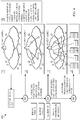
- FIG. 6 illustrates an embodiment working flow 600 for handling content dissemination into a CDN.
- the working flow 600 is an exemplary scheme implemented by the control elements (SDT, SDN, and SDP), e.g., as in domain controller 310, to configure the data plane for dissemination of content traffic for a CDN.
- the SDT component determines the logical data plane topology architecture, including determining the locations of content storages based on factors, such as content popularity level, and QoS information.
- the SDT may also use mobility tracking, network status, and QoE information.
- the SDT provides the decision to the SDN component.
- the SDN component maps the logical topology to a physical network resource, e.g., including allocating network resources (e.g., one or more paths or routes, bandwidth) to meet the required data plane architecture and QoS requirement.
- the SDN component operation may involve multiple-handshake and negotiation between the control components and/or the domain controllers.
- the SDN component operations may also use physical infrastructure abstraction information.
- the SDP component defines the data plane process functionality, e.g., as part of a data plane protocol, for each involved network node, e.g., including radio nodes, assigned by the SDN component.
- the control components interface with each other and negotiate for the best solution, for example to satisfy QoS with the minimum network resource used and/or maximize the operator/customer revenue.
- Adaptation to data plane architecture may also trigger remapping between the logical topology and physical network resource (by the SDN component), and reconfiguration of the data plane protocol (by the SDP component).
- FIG. 7 illustrates an embodiment working flow 700 for handling content delivery to customers in a CDN.
- the working flow 700 is an exemplary scheme implemented by the control elements (SDT, SDN, and SDP), e.g., as in domain controller 310, to configure the data plane for dissemination of CDN content delivery to users (e.g., consumers of content).
- the SDT component determines the logical data plane topology architecture, including, determining the locations of content sources, and intended user (or content consumer) for delivery based on factors, including content delivery/request and QoS information.
- the SDT may also use mobility tracking, network status, and QoE information.
- the SDT provides the decision to the SDN component.
- the SDN component maps the logical topology to a physical network resource, e.g., including allocating network resources (e.g., one or more paths or routes, bandwidth) to meet the required data plane architecture and QoS requirement.
- the SDN component operation may involve multiple-handshake and negotiation between the control components and/or the domain controllers.
- the SDN component operations may also use physical infrastructure abstraction information.
- the SDP component defines the data plane process functionality, e.g., as part of a data plane protocol, for each involved network node, e.g., including radio nodes, assigned by the SDN component.
- the control components interface with each other and negotiate for the best solution, for example to satisfy QoS with the minimum network resource used and/or maximize the operator/customer revenue. Additional on-going adaptation may also follow, such as according to consumer location change (user mobility) and customer changes. Such changes can trigger reconfiguration by the SDT component.
- Adaptation to data plane architecture may also trigger remapping between the logical topology and physical network resource (by the SDN component), and reconfiguration of the data plane protocol (by the SDP component).
- FIG 8 illustrates an embodiment of a configurable and multi-functional radio node 800.
- the radio node 800 is one node or component of a wireless or integrated network that can be configured, e.g., at the data plane level, with suitable radio node functionality using the control plane architecture described above, for instance by the SDP component.
- the radio node 800 is equipped with single or multiple configurable or built-in radio transmitter(s)/receiver(s).
- a transmitter/receiver of the radio node 800 can be customized to support both access link and backhaul link communications, with configurable carrier band, antenna steer, antenna (steering, beam-width, and/or other antenna features).
- the radio node 800 can also be equipped with suitable storage capability.
- the radio node may also perform a switch function, to operate as a receiver connection for a selected transmitter, e.g., based on instructions from the control plane.
- the configurable radio node 800 can include one or more multiple wireless/fabric backhaul functions with configurable band RF.
- the configurable radio node 800 can also include narrow beam backhaul functionality, e.g., at a higher RF band, a routing functionality, one or more configurable access link functions, in-band or out-of-band sensor functionality, or combinations thereof. Multiple types of multi-functional radio nodes 800 may be configured depending on the functionality implemented.
- Figure 9 illustrates an embodiment of an interface 900 between the control plane and a radio node/network node with configurable functionality at the data plane, such as the radio node 800.
- the control plane can be centralized and remote with respect to the radio node, for instance at a domain controller component, as in domain controller 310, or may be virtual cloud based.
- the depth of centralized radio control and coordination may be configurable. For instance, fast adaptation required control (e.g., link adaptation, fast error recovery) may be locally controlled at the radio node.
- Slow adaptation required control e.g., power control, spatial control, carrier coordination
- the interface 900 may include a SDP-to-data plane logical interface that configures, for the radio node, the set of data process functionality, workflow for handling /processing traffic and corresponding parameters and status.
- the interface 900 may include a SDN-to-data plane logical interface that configures the forwarding rule and radio operation parameters for the radio node.
- the interface 900 may also include a SDT-to-data plane logical interface that configures the content storage and traffic rate and compression rule and traffic filtering, for the radio node.
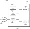
- FIG. 10 is a block diagram of an exemplary processing system 1000 that can be used to implement various embodiments. Specific devices may utilize all of the components shown, or only a subset of the components and levels of integration may vary from device to device. Furthermore, a device may contain multiple instances of a component, such as multiple processing units, processors, memories, transmitters, receivers, etc.
- the processing system 1000 may comprise a processing unit 1001 equipped with one or more input/output devices, such as a network interfaces, storage interfaces, and the like.
- the processing unit 1001 may include a central processing unit (CPU) 1010, a memory 1020, a mass storage device 1030, and an I/O interface 1060 connected to a bus.
- the bus may be one or more of any type of several bus architectures including a memory bus or memory controller, a peripheral bus or the like.
- the CPU 1010 may comprise any type of electronic data processor.
- the memory 1020 may comprise any type of system memory such as static random access memory (SRAM), dynamic random access memory (DRAM), synchronous DRAM (SDRAM), read-only memory (ROM), a combination thereof, or the like.
- the memory 1020 may include ROM for use at boot-up, and DRAM for program and data storage for use while executing programs.
- the memory 1020 is non-transitory.
- the mass storage device 1030 may comprise any type of storage device configured to store data, programs, and other information and to make the data, programs, and other information accessible via the bus.
- the mass storage device 1030 may comprise, for example, one or more of a solid state drive, hard disk drive, a magnetic disk drive, an optical disk drive, or the like.
- the processing unit 1001 also includes one or more network interfaces 1050, which may comprise wired links, such as an Ethernet cable or the like, and/or wireless links to access nodes or one or more networks 1080.
- the network interface 1050 allows the processing unit 1001 to communicate with remote units via the networks 1080.
- the network interface 1050 may provide wireless communication via one or more transmitters/transmit antennas and one or more receivers/receive antennas.
- the processing unit 1001 is coupled to a local-area network or a wide-area network for data processing and communications with remote devices, such as other processing units, the Internet, remote storage facilities, or the like.
Description
- The present invention relates to the field of network communications, and, in particular embodiments, to a method and a corresponding network component for a control plane reference model framework.
- Software-defined networking (SDN) provides a mapping between logical topology requirements and physical infrastructure resources. Radio coordination is part of SDN for radio access networks (RANs). The SDN in RAN generally manages routing and traffic engineering (TE) to provide a forwarding path and required bandwidth or rate for traffic flow over each link over the path (multiple routes are also possible). The SDN in RAN also manages radio coordination to provide on-demand configuration of radio node specification, including the access link/backhaul link and the carrier. The on-demand configuration may include selecting built-in components with different specifications. The on-demand configuration can also include coordinating the mapping/allocation of the 5-tuple wireless resource (time/frequency/code/ power/spatial) to active flows. However, as radio nodes functionality and RAN or other integrated network in general evolve, managing the control plane, such as in term of SDN framework, becomes challenging. There is a need for an improved control plane reference model and architecture for such networks including radio nodes and other nodes.
- In the publication titled, "Virtualized network infrastructure using Open Flow", Hideyuki Shimonishi et al, proposes a virtualized network infrastructure using Open Flow.
- Open Flow Switch Specification Version 1.3.1 published by Open Flow Networking Foundation, provides a basic framework and protocol for implementing a network switch based on OpenFlow protocol.
-
US 20110131252 relates to method and apparatus for physical/logical relationship mapping between resources. - The present disclosure provides a method according to
claim 1 and a network component according to claim 15. Further technical features are defined in the respective dependent claims. - For a more complete understanding of the present invention, and the advantages thereof, reference is now made to the following descriptions taken in conjunction with the accompanying drawing, in which:
-
Figure 1 illustrates a scenario of implementing multiple co-existing customized virtual networks at a control plane; -
Figure 2 illustrates an embodiment of a control plane architecture; -
Figure 3 illustrates an embodiment of control components within a domain controller; -
Figure 4 illustrates an embodiment working flow for handling content transmission between end-to-end customers; -
Figure 5 illustrates an embodiment working flow for handling machine-to-machine (M2M) communications; -
Figure 6 illustrates an embodiment working flow for handling content dissemination into a content delivery network (CDN); -
Figure 7 illustrates an embodiment working flow for handling content delivery to customers in a CDN; -
Figure 8 illustrates an embodiment of a configurable and multi-functional radio node; -
Figure 9 illustrates an embodiment of an interface between the control plane and radio node; and -
Figure 10 is a diagram of an exemplary processing system that can be used to implement various embodiments. - Corresponding numerals and symbols in the different figures generally refer to corresponding parts unless otherwise indicated. The figures are drawn to clearly illustrate the relevant aspects of the embodiments and are not necessarily drawn to scale.
- The making and using of the presently preferred embodiments are discussed in detail below. It should be appreciated, however, that the present invention provides many applicable inventive concepts that can be embodied in a wide variety of specific contexts. The specific embodiments discussed are merely illustrative of specific ways to make and use the invention, and do not limit the scope of the invention.
- Current and future wireless networks or integrated wireless and non-wireless networks are expected to enable high flexibility, high efficiency, high openness and customization to customers (e.g., virtual network operators) and consumers. Currently, there is no systematic description of control plane functionality in wireless or integrated networks. Such networks also lack systematic description of control plane functionality workflow. Further, there is no definition of interface between the data plane (e.g., at a radio node level) and the different control plane components.
- To enable such high-functioning wireless or integrated (combined wireless and non-wireless) networks, embodiments are provided herein to present a framework for a control plane reference model for such types of networks. The embodiments include identifying key control functionality of the control plane, and providing a control plane architecture to enable the control functionality of multiple control components. Additionally, interface between the control components are provided. Various workflows among the control components are also provided for exemplary scenarios.
- To avoid the excessive complexity of Software-defined networking (SDN) and process complexity of network nodes in data plane, software defined topology (SDT) functionality is introduced to control plane to define service/application/virtual network (VN) specific data plane topology based on service logical topology before SDN. A service can be any network service provided by network resources, such as a data service, a voice service, a video service, other network based services, or combinations thereof. In order to provide a fully customized network, software defined data plane protocol (SDP) functionality is also introduced in control plane to define the service/application/VN specific data process. In control plane, in addition to a SDN functionality component, SDT and SDP components are also included. The embodiments also include identifying radio node functionality for improved or future wireless networks, and interface between the remote control plane and such radio nodes (e.g., at the data plane). This framework of reference model and interface design can be used in the systematic design, development of algorithms, and control mechanisms of future wireless or integrated network architecture.
-
Figure 1 illustrates using multiple co-existing customizedvirtual networks 100 that can be implemented using the control plane functionality herein and further using integratedphysical network resources 120. The integrated physical network resources may include multiple domains orsub-networks 150. The co-existing customizedvirtual networks 100 achieved using the control plane functionality can be configured according to various logical architectures, including for example an arbitrary architecture such as for content delivery, a hierarchical star architecture such as for machine-to-machine (M2M) communications, and a flat data plane architecture such as for between end customers. -
Figure 2 shows an embodiment of acontrol plane architecture 200 that enables a configurable data plane architecture, such as the configurabledata plane architecture 100, and allows the functioning and operation of the various configured VNs 102 at the data plane. Thecontrol plane architecture 200 is a logical control architecture that has a hierarchical structure to handle multiplegeographic domains 250, which may be networks, sub-networks, or other types of network domains. A plurality ofdomain controllers 220 assigned to thedifferent domains 250 are each configured with three control elements, including a software defined topology (SDT) component, a software defined network (SDN) component, and a software defined protocol (SDP) component. These control components may be implemented using software, hardware, or both. The physical implementation of the control functionality of the components can be implemented by a network entity or location (e.g., thedomain controllers 220 corresponds to a node or data center), or alternatively can be virtual cloud based (e.g., in a distributed manner across a network or virtual network referred which is referred to as a cloud). The SDT component provides on-demand, configurable and customized logical data plane architecture. The SDN component provides on-demand customized resource management to meet the requirement of the defined data plane architecture. The SDP component provides on-demand, configurable and customized data plane process protocol that may be both radio related and non-radio related. The size of thedomain 250 for eachindividual domain controller 220 can be different and can be dynamically configured. Additionally, aninter-domain coordinator 210 can be used to coordinate inter-domain control functionality between thedifferent domain controllers 220. Eachdomain controller 220 can communicate with theinter-domain coordinator 210 via a first interface (e.g., via API), referred to inFigure 2 as a domain control-to-orchestrator (C-O) interface. Thedomain controller 220 can communicate with anotherdomain controller 220 via a second interface, referred to inFigure 2 as a domain control-to-domain control (C-C) interface. Thedomain controller 220 also communicates with its respective domain via a third interface, referred to inFigure 2 as a domain control-to-physical network (C-P) interface (or control plane-to-data plane (C-D) interface. - In an embodiment, the network nodes belong to a first layer, e.g., at the
various domains 250, and are abstracted (or grouped) into virtual nodes at a second layer. Thus, the second layer comprises virtual nodes each being a group of multiple physical nodes at the first layer. The virtual nodes at the second layer are treated by the SDT/SDN/SDP components, e.g., in thedomain controllers 220, as individual nodes having corresponding input and output parameters for control and configuration. As such, the network nodes at the first layer, which form the virtual nodes, can be transparent to the SDT/SDN/SDP components. Multiple abstraction levels may be used to group nodes into higher abstraction layer nodes. For example, the network nodes at the physical network layer may be grouped into virtual nodes at a first abstraction layer. The virtual nodes at the first abstraction layer may further be grouped into virtual nodes at a second abstraction layer, which may then be treated by the SDT/SDN/SDP components as individual nodes. This network layer abstraction simplifies handling and managing a large number of nodes in multiple networks or domains by the SDT/SDN/SDP components. -
Figure 3 shows an embodiment ofcontrol components 300 within adomain controller 310. Thecontrol components 300 include aSDT component 311, aSDN component 312, and aSDP element 313 with respective control functionalities, as described above. The control components of thedomain controller 310 provide the control functionality to thecorresponding domain 320. The integratedphysical network 320 may include or the corresponding domain may be a wireless network including radio nodes. Thedomain controller 310 may be managed or operated by an operator to handle, on-demand, communication and information delivery for a service or a VN. To perform the control functionality of thecontrol components 300, thedomain controller 310 receives input via API (application programming interface) from an application/service/VN operator to obtain service requirement (e.g., service logical topology, quality of service, preferred cost). Thedomain controller 310 also receives input information from the integratedphysical network 320, including network status analysis information, infrastructure abstraction information, mobility track information (e.g., for mobile users), and/or quality of service (QoS) analysis information. The control elements at thedomain controller 310 processes such information to provide a customized data plane for handling communications and data forwarding for a service or VN, by resource management such as path/bandwidth or rate allocation to meet the requirement of the defined data plane, and the data plane process protocol for forwarding/processing of associated traffic. The decisions from the control elements at thedomain controller 310 are sent to the data plane (the network nodes) via the interface between control plane and data plane (I-CD). The interface between the applications/service/virtual network operator and control plane includes information, such as, service logical topology, application/traffic characteristics, end-customer mobility distribution, required service QoS, and/or other relevant information for enabling an applications/service/virtual network. The interface (I-Mob) between Mobility management/track and control plane includes information such as current location of end-customers, e.g., geographic location, location relative to network, and possible prediction of location. The interface (I-QoE) between control plane and Delivered QoE analysis includes QoE analysis information such as based on QoE information (e.g., rate, packet loss rate, black screen time). The interface (I-DC-QoE) between data plane and control plane includes the QoE information. The interface (I-abs) between control plane and infrastructure abstraction includes information such as effective spectra efficiency of mobile terminals. The interface (I-NS) between control pane and network status analysis includes information such as network load. The interface (I-DC-NS) between data plane and control plane includes information such as node load and packet drop rates. The interface (I-CD) includes information such as routing information, data process functionality, and work flow. -
Figure 4 shows anembodiment working flow 400 for handling content/information transmission between end-to-end customers. The workingflow 400 is an exemplary scheme implemented by the control elements (SDT, SDN, and SDP), e.g., using thecontrol plane architecture 200, to configure the virtual network for forwarding/processing/handling traffic between end-to-end customers. The SDT component determines the logical data plane topology architecture and source/destination locations based on factors, such as service/connectivity requirements, available network resource, QoS requirement, and/or other factors. As part of determining the logical topology for the data plane, the SDT component selects network elements or nodes and required service quality necessary to implement or enable the data plane (for a service or VN). For instance, the selected elements may be at least a source location/node and a destination location/node for handling content/information transmission between end-to-end customers/devices. The SDT also uses mobility tracking, network status, and quality of experience (QoE) information. The SDT provides the decision to the SDN component. - The SDN component maps the logical topology (from the SDT component) to a physical network resource. This process includes allocating network resources (e.g., one or more paths or routes, bandwidth) to meet the required data plane architecture and QoS requirement. The SDN component operation may involve multiple-handshake and negotiation between the control components and/or the inter-domain controllers. The SDN component operations may also use physical infrastructure abstraction information. According to the SDN component decision, the SDP component defines the data plane process functionality, e.g., as part of a data plane protocol, for each involved network node assigned by the SDN component, including radio nodes for wireless networks if considered. The control components interface with each other and negotiate for the best solution, for example to satisfy QoS with the minimum network resource used and/or maximize the operator/customer revenue. Additional on-going adaptation may also follow. For instance, the SDT component may need to reconfigure the logical data plane architecture to adapt to dynamic changes such as change in required end-to-end service/flow rate due to source rate adaptation to handle network congestion or receiver behavior at the nodes/end user's equipment, change in service/flow rate in some links on the forwarding path caused by compression due to link congestion, or change of source or destination location due to node/user mobility. The SDN needs to adapt to the modification of logical data plane topology to remap logical connectivity to physical network resource, and for reconfiguring (by the SDP component) the data plane protocol. In an embodiment, the SDT, SDN, and SDP iteratively or continuously implement their corresponding control functionality, thus adjusting dynamically to changes that may occur for a service or virtual network. This provides dynamic change to the data plane topology and necessary remapping into adjusted network resources according to the changes.
-
Figure 5 shows anembodiment working flow 500 for handling machine-to-machine (M2M) communications. The workingflow 500 is an exemplary scheme implemented by the control elements (SDT, SDN, and SDP), e.g., as indomain controller 310, to configure the data plane for forwarding and handling traffic for M2M communications, e.g., between machines such as sensors or meters absent of direct user involvement. The SDT component determines the logical data plane topology architecture, e.g., for a first VN, based on factors such as traffic characteristics and end-devices distribution, connectivity/QoS requirements, available network resource, and/or other factors. The SDT may also use mobility tracking, network status, and QoE information. The SDT provides the decision to the SDN component. The SDN component maps the logical topology (from the SDT component) to a physical network resource. This process includes allocating network resources (e.g., one or more paths or routes, bandwidth) to meet the required data plane architecture and QoS requirement. The SDN component operation may involve multiple-handshake and negotiation between the control components and/or the inter-domain controllers. The SDN component operations may also use physical infrastructure abstraction information. According to the SDN component decision, the SDP component defines the data plane process functionality, e.g., as part of a data plane protocol, for each involved network node assigned by the SDN component, including radio nodes for wireless networks if considered. The control components interface with each other and negotiate for the best solution, for example to satisfy QoS with the minimum network resource used and/or maximize the operator/customer revenue. Additional on-going adaptation may also follow, such as logical topology changes (by the SDT component) due to traffic distribution (e.g., mobility) change and network status change, remapping (by the SDN component) the logical topology to physical network resource, and reconfiguring (by the SDP component) the data plane protocol. -
Figure 6 illustrates anembodiment working flow 600 for handling content dissemination into a CDN. The workingflow 600 is an exemplary scheme implemented by the control elements (SDT, SDN, and SDP), e.g., as indomain controller 310, to configure the data plane for dissemination of content traffic for a CDN. The SDT component determines the logical data plane topology architecture, including determining the locations of content storages based on factors, such as content popularity level, and QoS information. The SDT may also use mobility tracking, network status, and QoE information. The SDT provides the decision to the SDN component. The SDN component maps the logical topology to a physical network resource, e.g., including allocating network resources (e.g., one or more paths or routes, bandwidth) to meet the required data plane architecture and QoS requirement. The SDN component operation may involve multiple-handshake and negotiation between the control components and/or the domain controllers. The SDN component operations may also use physical infrastructure abstraction information. According to the SDN component decision, the SDP component defines the data plane process functionality, e.g., as part of a data plane protocol, for each involved network node, e.g., including radio nodes, assigned by the SDN component. The control components interface with each other and negotiate for the best solution, for example to satisfy QoS with the minimum network resource used and/or maximize the operator/customer revenue. Additional on-going adaptation may also follow, such as according to content popularity change, consumer distribution change, and network status changes. Such changes can trigger reconfiguration by the SDT component. Adaptation to data plane architecture may also trigger remapping between the logical topology and physical network resource (by the SDN component), and reconfiguration of the data plane protocol (by the SDP component). -
Figure 7 illustrates anembodiment working flow 700 for handling content delivery to customers in a CDN. The workingflow 700 is an exemplary scheme implemented by the control elements (SDT, SDN, and SDP), e.g., as indomain controller 310, to configure the data plane for dissemination of CDN content delivery to users (e.g., consumers of content). The SDT component determines the logical data plane topology architecture, including, determining the locations of content sources, and intended user (or content consumer) for delivery based on factors, including content delivery/request and QoS information. The SDT may also use mobility tracking, network status, and QoE information. The SDT provides the decision to the SDN component. The SDN component maps the logical topology to a physical network resource, e.g., including allocating network resources (e.g., one or more paths or routes, bandwidth) to meet the required data plane architecture and QoS requirement. The SDN component operation may involve multiple-handshake and negotiation between the control components and/or the domain controllers. The SDN component operations may also use physical infrastructure abstraction information. According to the SDN component decision, the SDP component defines the data plane process functionality, e.g., as part of a data plane protocol, for each involved network node, e.g., including radio nodes, assigned by the SDN component. The control components interface with each other and negotiate for the best solution, for example to satisfy QoS with the minimum network resource used and/or maximize the operator/customer revenue. Additional on-going adaptation may also follow, such as according to consumer location change (user mobility) and customer changes. Such changes can trigger reconfiguration by the SDT component. - Adaptation to data plane architecture may also trigger remapping between the logical topology and physical network resource (by the SDN component), and reconfiguration of the data plane protocol (by the SDP component).
-
Figure 8 illustrates an embodiment of a configurable andmulti-functional radio node 800. Theradio node 800 is one node or component of a wireless or integrated network that can be configured, e.g., at the data plane level, with suitable radio node functionality using the control plane architecture described above, for instance by the SDP component. Theradio node 800 is equipped with single or multiple configurable or built-in radio transmitter(s)/receiver(s). A transmitter/receiver of theradio node 800 can be customized to support both access link and backhaul link communications, with configurable carrier band, antenna steer, antenna (steering, beam-width, and/or other antenna features). Theradio node 800 can also be equipped with suitable storage capability. The radio node may also perform a switch function, to operate as a receiver connection for a selected transmitter, e.g., based on instructions from the control plane. Theconfigurable radio node 800 can include one or more multiple wireless/fabric backhaul functions with configurable band RF. Theconfigurable radio node 800 can also include narrow beam backhaul functionality, e.g., at a higher RF band, a routing functionality, one or more configurable access link functions, in-band or out-of-band sensor functionality, or combinations thereof. Multiple types ofmulti-functional radio nodes 800 may be configured depending on the functionality implemented. -
Figure 9 illustrates an embodiment of an interface 900 between the control plane and a radio node/network node with configurable functionality at the data plane, such as theradio node 800. The control plane can be centralized and remote with respect to the radio node, for instance at a domain controller component, as indomain controller 310, or may be virtual cloud based. The depth of centralized radio control and coordination may be configurable. For instance, fast adaptation required control (e.g., link adaptation, fast error recovery) may be locally controlled at the radio node. Slow adaptation required control (e.g., power control, spatial control, carrier coordination) may be remote (centralized) controlled at the control plane. The interface 900 may include a SDP-to-data plane logical interface that configures, for the radio node, the set of data process functionality, workflow for handling /processing traffic and corresponding parameters and status. The interface 900 may include a SDN-to-data plane logical interface that configures the forwarding rule and radio operation parameters for the radio node. The interface 900 may also include a SDT-to-data plane logical interface that configures the content storage and traffic rate and compression rule and traffic filtering, for the radio node. -
Figure 10 is a block diagram of anexemplary processing system 1000 that can be used to implement various embodiments. Specific devices may utilize all of the components shown, or only a subset of the components and levels of integration may vary from device to device. Furthermore, a device may contain multiple instances of a component, such as multiple processing units, processors, memories, transmitters, receivers, etc. Theprocessing system 1000 may comprise aprocessing unit 1001 equipped with one or more input/output devices, such as a network interfaces, storage interfaces, and the like. Theprocessing unit 1001 may include a central processing unit (CPU) 1010, amemory 1020, amass storage device 1030, and an I/O interface 1060 connected to a bus. The bus may be one or more of any type of several bus architectures including a memory bus or memory controller, a peripheral bus or the like. - The
CPU 1010 may comprise any type of electronic data processor. Thememory 1020 may comprise any type of system memory such as static random access memory (SRAM), dynamic random access memory (DRAM), synchronous DRAM (SDRAM), read-only memory (ROM), a combination thereof, or the like. In an embodiment, thememory 1020 may include ROM for use at boot-up, and DRAM for program and data storage for use while executing programs. In embodiments, thememory 1020 is non-transitory. Themass storage device 1030 may comprise any type of storage device configured to store data, programs, and other information and to make the data, programs, and other information accessible via the bus. Themass storage device 1030 may comprise, for example, one or more of a solid state drive, hard disk drive, a magnetic disk drive, an optical disk drive, or the like. - The
processing unit 1001 also includes one ormore network interfaces 1050, which may comprise wired links, such as an Ethernet cable or the like, and/or wireless links to access nodes or one ormore networks 1080. Thenetwork interface 1050 allows theprocessing unit 1001 to communicate with remote units via thenetworks 1080. For example, thenetwork interface 1050 may provide wireless communication via one or more transmitters/transmit antennas and one or more receivers/receive antennas. In an embodiment, theprocessing unit 1001 is coupled to a local-area network or a wide-area network for data processing and communications with remote devices, such as other processing units, the Internet, remote storage facilities, or the like.
Claims (15)
- A method by a network component (310) for implementing control plane functionality to configure a data plane at a plurality of network nodes, wherein the network component comprises a software defined topology, SDT component (311), a software defined networking, SDN component (312), and a software defined protocol, SDP component (313), the method comprising:determining, using the software defined topology, SDT component (311), a data plane logical topology indicating a plurality of selected nodes and and a logical architecture connecting selected nodes;mapping, using the software defined networking, SDN component (312), the data plane logical topology to a physical network, the mapping comprising allocating network nodes of a service or virtual network, wherein the allocated network nodes include the selected nodes and network resources; anddefining, using the software defined protocol, SDP component (313), a data plane protocol including data plane process functionality for the allocated network nodes;wherein the method further comprises:determining a network status analysis information by a network status analysis component according to network status information including node load or packet drop rates obtained from the data plane via a first interface between the control plane and the data plane, anddetermining a QoE analysis information by a QoE analysis component according to rate, packet loss rate, or black screen time experience information obtained from the data plane via a second interface between the control plane and the data plane;SDT, SDN and SDP, iteratively implementing their corresponding control functionality to dynamically adjust to changes in the service or virtual network;wherein centralized control and coordination in said network component (310) is configured such that fast adaptation control is performed locally in the network nodes and slow adaptation control is performed in said network component (310) implementing the control plane.
- The method of claim 1, wherein determining the data plane logical topology includes configuring at least one of traffic filtering, traffic aggregation, traffic convergence, and load balancing functionality for the selected nodes, wherein mapping the data plane logical topology to the physical network includes configuring data forwarding rules for the network nodes, and wherein defining the data plane protocol includes configuring a set of data process functionality, workflow for handling and processing traffic, and corresponding parameters and status information for the network nodes.
- The method of claim 1 further comprising configuring radio operation parameters of a radio node from the network nodes.
- The method of claim 1 further comprising exchanging information between each of the SDN component, the SDT component, and the SDP component to negotiate and cooperate for configuring data plane for the network nodes.
- The method of claim 1, wherein the data plane logical topology is determined and mapped to the physical network
according to at least one of mobility tracking, network status, quality of experience, QoE information, and network node capability; or
for handling traffic transmission between end-to-end customers according to at least one of service requirement, connectivity requirement, available network resource, and the QoS requirement; or
for handling machine-to-machine, M2M communications according to at least one of traffic characteristics, end-devices distribution, connectivity requirement, available network resource, and the QoS requirement; or
for handling content dissemination into a network according to at least one of content storage based factors content popularity, and the QoS requirement, and wherein determining the data plane logical topology includes determining destinations for content cache in the network; or
for handling content delivery to customers in a content delivery network, CDN according to at least one of destination of content, requesting mobile or terminal, and the QoS requirement, and wherein determining the data plane logical topology includes determining sources for content delivery. - The method of claim 1, wherein allocating network resources to meet the data plane logical topology and the QoS requirement includes allocating, for the network nodes, a path or multiple paths and corresponding bandwidth in the physical network.
- The method of claim 1, wherein the selected node of the data plane logical topology indicates a source location and a destination location of the service or virtual network, and further indicates a logical architecture to connect the selected nodes at data plane and attributes of connections of the selected nodes, the data plane attributes including at least one of rate and delay attributes.
- The method of claim 1, wherein physical network is divided into a plurality of control domains, and wherein the SDT component, the SDN component, and the SDP component are assigned to a first domain from the plurality of control domains in the physical network.
- The method of claim 8 further comprising exchanging information with a second SDN component, a second SDT component, or a second SDP component, the second SDP component being assigned to a second domain from the plurality of control domains to cooperate for configuring data plane for the network nodes in the first domain or the second domain.
- The method of claim 1, wherein the network nodes correspond to a first layer and are abstracted into virtual nodes at a second layer, and wherein the data plane logical topology is determined, using the SDT, for the virtual nodes at the second layer.
- The method of claim 1 further comprising:receiving, at a control plane via a first interface, network status analysis information including network load from a network status analysis component;receiving, at the control plane via a second interface, infrastructure abstraction information including effective spectra efficiency of mobile terminals from an infrastructure abstraction component;receiving, at the control plane via a third interface, mobility management and tracking information including current geographic locations, locations relative to network, or predictions of locations of end-customers from a mobility management and tracking component;receiving, at the control plane via a fourth interface, quality of experience, QoE analysis information from a QoE analysis component; andproviding, via a fifth interface at the control plane, control functionality decisions including routing information, data process functionality, and work flow to a service or virtual network.
- The method of claim 1 further comprising repeating steps for determining the data plane logical topology using the SDT, mapping the data plane logical topology to the physical network using the SDN, and defining the data plane protocol using the SDP data plane process functionality for the allocated network nodes, wherein repeating the steps adjusts dynamically to changes related to the service or virtual network.
- The method of claim 1, wherein the data plane logical topology is determined according to a logical topology provided by a customer and enabling information exchange of the service or virtual network.
- The method of claim 13, wherein the customer is an end-customer, a service operator, or a virtual network operator.
- A network component (310) comprising:at least one processor; anda non-transitory computer readable storage medium storing programming for execution by the at least one processor, the programming including instructions to implement actions in accordance with a method in any one of claims 1 to 14.
Applications Claiming Priority (3)
| Application Number | Priority Date | Filing Date | Title |
|---|---|---|---|
| US201361810590P | 2013-04-10 | 2013-04-10 | |
| US14/245,830 US10291515B2 (en) | 2013-04-10 | 2014-04-04 | System and method for a control plane reference model framework |
| PCT/CN2014/075035 WO2014166399A1 (en) | 2013-04-10 | 2014-04-10 | System and method for a control plane reference model framework |
Publications (3)
| Publication Number | Publication Date |
|---|---|
| EP2979397A1 EP2979397A1 (en) | 2016-02-03 |
| EP2979397A4 EP2979397A4 (en) | 2016-08-17 |
| EP2979397B1 true EP2979397B1 (en) | 2021-06-30 |
Family
ID=51686721
Family Applications (1)
| Application Number | Title | Priority Date | Filing Date |
|---|---|---|---|
| EP14783405.5A Active EP2979397B1 (en) | 2013-04-10 | 2014-04-10 | System and method for a control plane reference model framework |
Country Status (4)
| Country | Link |
|---|---|
| US (2) | US10291515B2 (en) |
| EP (1) | EP2979397B1 (en) |
| CN (2) | CN109450695A (en) |
| WO (1) | WO2014166399A1 (en) |
Families Citing this family (135)
| Publication number | Priority date | Publication date | Assignee | Title |
|---|---|---|---|---|
| WO2014190523A1 (en) * | 2013-05-30 | 2014-12-04 | 华为技术有限公司 | Scheduling method, apparatus and system |
| US9525726B2 (en) * | 2013-06-24 | 2016-12-20 | Nec Corporation | Compute followed by network load balancing procedure for embedding cloud services in software-defined flexible-grid optical transport networks |
| US9473573B2 (en) * | 2013-08-07 | 2016-10-18 | Nec Corporation | Network followed by compute load balancing procedure for embedding cloud services in software-defined flexible-grid optical transport networks |
| US10374918B2 (en) | 2013-12-04 | 2019-08-06 | Radware, Ltd. | Method and system for configuring behavioral network intelligence system using network monitoring programming language |
| EP3105946B1 (en) | 2014-03-05 | 2018-09-19 | Huawei Technologies Co., Ltd. | System and method for a customized fifth generation (5g) network |
| US9781004B2 (en) | 2014-10-16 | 2017-10-03 | Cisco Technology, Inc. | Discovering and grouping application endpoints in a network environment |
| CN107005431B (en) * | 2014-11-21 | 2020-01-31 | 华为技术有限公司 | System and method for changing service-based data plane configuration |
| US9622019B2 (en) | 2014-11-28 | 2017-04-11 | Huawei Technologies Co., Ltd. | Systems and methods for generating a virtual network topology for M2M communications |
| EP3215953B1 (en) * | 2014-11-28 | 2019-02-20 | Huawei Technologies Co. Ltd. | Systems and methods for providing customized virtual wireless networks based on service oriented network auto-creation |
| US9445279B2 (en) * | 2014-12-05 | 2016-09-13 | Huawei Technologies Co., Ltd. | Systems and methods for placing virtual serving gateways for mobility management |
| CN105744386A (en) * | 2014-12-12 | 2016-07-06 | 中兴通讯股份有限公司 | Business processing method and business processing device |
| CN104518993A (en) * | 2014-12-29 | 2015-04-15 | 华为技术有限公司 | Allocation method, device and system for communication paths of cloud network |
| CN107111521B (en) * | 2015-01-13 | 2020-11-06 | 华为技术有限公司 | System and method for dynamic orchestration |
| JP6405245B2 (en) * | 2015-01-14 | 2018-10-17 | 株式会社日立製作所 | Communication system and setting method |
| US10298466B2 (en) * | 2015-01-20 | 2019-05-21 | Huawei Technologies Co., Ltd. | Systems and methods for SDT to interwork with NFV and SDN |
| JP6552130B2 (en) | 2015-01-20 | 2019-07-31 | ホアウェイ・テクノロジーズ・カンパニー・リミテッド | Method and apparatus for NFV management and orchestration |
| KR102286882B1 (en) | 2015-03-06 | 2021-08-06 | 삼성전자 주식회사 | Method and apparatus for managing quality of experience |
| US20180048489A1 (en) * | 2015-03-06 | 2018-02-15 | Zte Corporation (China) | Method and system for establishing and managing multi-domain virtual tunnel (mvt) |
| US10028167B2 (en) | 2015-03-08 | 2018-07-17 | Alcatel-Lucent Usa Inc. | Optimizing quality of service in a content distribution network using software defined networking |
| WO2016159113A1 (en) * | 2015-03-31 | 2016-10-06 | 日本電気株式会社 | Control device, control method, and program |
| CN107534567A (en) * | 2015-04-17 | 2018-01-02 | 科锐安特股份有限公司 | For the configuration system configured to the control plane of software defined network |
| BR112017022434A2 (en) * | 2015-04-24 | 2018-07-10 | Mediatek Inc. | A FLEXIBLE MACRO-ASSISTED USER-PLANE ARCHITECTURE WITH MILLIMETER-WAVE SMALL CELLS |
| CN106302153B (en) * | 2015-05-11 | 2020-02-07 | 中兴通讯股份有限公司 | Multi-domain controller, single-domain controller, software defined optical network system and method |
| US9860339B2 (en) * | 2015-06-23 | 2018-01-02 | At&T Intellectual Property I, L.P. | Determining a custom content delivery network via an intelligent software-defined network |
| US9756121B2 (en) * | 2015-06-24 | 2017-09-05 | International Business Machines Corporation | Optimizing routing and load balancing in an SDN-enabled cloud during enterprise data center migration |
| US9575689B2 (en) | 2015-06-26 | 2017-02-21 | EMC IP Holding Company LLC | Data storage system having segregated control plane and/or segregated data plane architecture |
| US9832797B2 (en) | 2015-06-29 | 2017-11-28 | At&T Intellectual Property I, L.P. | Mobility network function consolidation |
| US20170031986A1 (en) * | 2015-07-31 | 2017-02-02 | Huawei Technologies Co., Ltd. | Method and System for Providing Integrated Virtualized Database Management and Software Defined Network Topology |
| US10985990B2 (en) | 2015-09-15 | 2021-04-20 | Huawei Technologies Co., Ltd. | Software defined topology (SDT) for user plane |
| US10091295B1 (en) | 2015-09-23 | 2018-10-02 | EMC IP Holding Company LLC | Converged infrastructure implemented with distributed compute elements |
| US9438478B1 (en) * | 2015-11-13 | 2016-09-06 | International Business Machines Corporation | Using an SDN controller to automatically test cloud performance |
| US10104171B1 (en) | 2015-11-25 | 2018-10-16 | EMC IP Holding Company LLC | Server architecture having dedicated compute resources for processing infrastructure-related workloads |
| US10772101B2 (en) | 2015-12-08 | 2020-09-08 | Huawei Technologies Co., Ltd. | Systems and methods for determining air interface configuration |
| US10536946B2 (en) * | 2015-12-08 | 2020-01-14 | Huawei Technologies Co., Ltd. | Method and system for performing network slicing in a radio access network |
| US10356608B2 (en) | 2016-02-18 | 2019-07-16 | Huawei Technologies Co., Ltd. | System and method of user equipment state configurations |
| US10469374B2 (en) | 2016-03-30 | 2019-11-05 | Futurewei Technologies, Inc. | Multiple provider framework for virtual switch data planes and data plane migration |
| US10681150B2 (en) * | 2016-03-31 | 2020-06-09 | Huawei Technologies Co., Ltd. | Systems and methods for management plane—control plane interaction in software defined topology management |
| US10250491B2 (en) * | 2016-05-09 | 2019-04-02 | Qualcomm Incorporated | In-flow packet prioritization and data-dependent flexible QoS policy |
| US10149193B2 (en) | 2016-06-15 | 2018-12-04 | At&T Intellectual Property I, L.P. | Method and apparatus for dynamically managing network resources |
| US10608928B2 (en) * | 2016-08-05 | 2020-03-31 | Huawei Technologies Co., Ltd. | Service-based traffic forwarding in virtual networks |
| EP3523934A1 (en) * | 2016-10-04 | 2019-08-14 | Telefonaktiebolaget LM Ericsson (PUBL) | Physical path control in hierarchical networks |
| US20180123896A1 (en) * | 2016-11-01 | 2018-05-03 | Huawei Technologies Co., Ltd. | Systems and methods for hierarchical network management |
| US10284730B2 (en) | 2016-11-01 | 2019-05-07 | At&T Intellectual Property I, L.P. | Method and apparatus for adaptive charging and performance in a software defined network |
| US10454836B2 (en) | 2016-11-01 | 2019-10-22 | At&T Intellectual Property I, L.P. | Method and apparatus for dynamically adapting a software defined network |
| US10505870B2 (en) | 2016-11-07 | 2019-12-10 | At&T Intellectual Property I, L.P. | Method and apparatus for a responsive software defined network |
| US10469376B2 (en) | 2016-11-15 | 2019-11-05 | At&T Intellectual Property I, L.P. | Method and apparatus for dynamic network routing in a software defined network |
| US10039006B2 (en) | 2016-12-05 | 2018-07-31 | At&T Intellectual Property I, L.P. | Method and system providing local data breakout within mobility networks |
| US10374829B2 (en) * | 2017-01-13 | 2019-08-06 | Microsoft Technology Licensing, Llc | Telecommunications network with data centre deployment |
| WO2018136105A1 (en) * | 2017-01-23 | 2018-07-26 | Huawei Technologies Co., Ltd | System and method for fair resource allocation |
| CN106851738A (en) * | 2017-01-25 | 2017-06-13 | 南京邮电大学 | Towards the software definition wireless network architecture and method of the small base station super-intensive networkings of LTE |
| US10264075B2 (en) * | 2017-02-27 | 2019-04-16 | At&T Intellectual Property I, L.P. | Methods, systems, and devices for multiplexing service information from sensor data |
| US10469286B2 (en) | 2017-03-06 | 2019-11-05 | At&T Intellectual Property I, L.P. | Methods, systems, and devices for managing client devices using a virtual anchor manager |
| US10623264B2 (en) | 2017-04-20 | 2020-04-14 | Cisco Technology, Inc. | Policy assurance for service chaining |
| US10560328B2 (en) | 2017-04-20 | 2020-02-11 | Cisco Technology, Inc. | Static network policy analysis for networks |
| US10826788B2 (en) | 2017-04-20 | 2020-11-03 | Cisco Technology, Inc. | Assurance of quality-of-service configurations in a network |
| US10749796B2 (en) | 2017-04-27 | 2020-08-18 | At&T Intellectual Property I, L.P. | Method and apparatus for selecting processing paths in a software defined network |
| US10819606B2 (en) | 2017-04-27 | 2020-10-27 | At&T Intellectual Property I, L.P. | Method and apparatus for selecting processing paths in a converged network |
| US10212289B2 (en) | 2017-04-27 | 2019-02-19 | At&T Intellectual Property I, L.P. | Method and apparatus for managing resources in a software defined network |
| US10673751B2 (en) | 2017-04-27 | 2020-06-02 | At&T Intellectual Property I, L.P. | Method and apparatus for enhancing services in a software defined network |
| US10382903B2 (en) | 2017-05-09 | 2019-08-13 | At&T Intellectual Property I, L.P. | Multi-slicing orchestration system and method for service and/or content delivery |
| US10257668B2 (en) | 2017-05-09 | 2019-04-09 | At&T Intellectual Property I, L.P. | Dynamic network slice-switching and handover system and method |
| US10581694B2 (en) | 2017-05-31 | 2020-03-03 | Cisco Technology, Inc. | Generation of counter examples for network intent formal equivalence failures |
| US10812318B2 (en) | 2017-05-31 | 2020-10-20 | Cisco Technology, Inc. | Associating network policy objects with specific faults corresponding to fault localizations in large-scale network deployment |
| US10693738B2 (en) | 2017-05-31 | 2020-06-23 | Cisco Technology, Inc. | Generating device-level logical models for a network |
| US10439875B2 (en) | 2017-05-31 | 2019-10-08 | Cisco Technology, Inc. | Identification of conflict rules in a network intent formal equivalence failure |
| US10554483B2 (en) | 2017-05-31 | 2020-02-04 | Cisco Technology, Inc. | Network policy analysis for networks |
| US10505816B2 (en) | 2017-05-31 | 2019-12-10 | Cisco Technology, Inc. | Semantic analysis to detect shadowing of rules in a model of network intents |
| US10623271B2 (en) | 2017-05-31 | 2020-04-14 | Cisco Technology, Inc. | Intra-priority class ordering of rules corresponding to a model of network intents |
| US20180351788A1 (en) | 2017-05-31 | 2018-12-06 | Cisco Technology, Inc. | Fault localization in large-scale network policy deployment |
| US10887130B2 (en) | 2017-06-15 | 2021-01-05 | At&T Intellectual Property I, L.P. | Dynamic intelligent analytics VPN instantiation and/or aggregation employing secured access to the cloud network device |
| US10904101B2 (en) | 2017-06-16 | 2021-01-26 | Cisco Technology, Inc. | Shim layer for extracting and prioritizing underlying rules for modeling network intents |
| US10587621B2 (en) | 2017-06-16 | 2020-03-10 | Cisco Technology, Inc. | System and method for migrating to and maintaining a white-list network security model |
| US10686669B2 (en) * | 2017-06-16 | 2020-06-16 | Cisco Technology, Inc. | Collecting network models and node information from a network |
| US10547715B2 (en) | 2017-06-16 | 2020-01-28 | Cisco Technology, Inc. | Event generation in response to network intent formal equivalence failures |
| US11469986B2 (en) | 2017-06-16 | 2022-10-11 | Cisco Technology, Inc. | Controlled micro fault injection on a distributed appliance |
| US10574513B2 (en) | 2017-06-16 | 2020-02-25 | Cisco Technology, Inc. | Handling controller and node failure scenarios during data collection |
| US11645131B2 (en) * | 2017-06-16 | 2023-05-09 | Cisco Technology, Inc. | Distributed fault code aggregation across application centric dimensions |
| US10498608B2 (en) | 2017-06-16 | 2019-12-03 | Cisco Technology, Inc. | Topology explorer |
| US11150973B2 (en) | 2017-06-16 | 2021-10-19 | Cisco Technology, Inc. | Self diagnosing distributed appliance |
| US10560355B2 (en) | 2017-06-19 | 2020-02-11 | Cisco Technology, Inc. | Static endpoint validation |
| US10567229B2 (en) | 2017-06-19 | 2020-02-18 | Cisco Technology, Inc. | Validating endpoint configurations between nodes |
| US10437641B2 (en) | 2017-06-19 | 2019-10-08 | Cisco Technology, Inc. | On-demand processing pipeline interleaved with temporal processing pipeline |
| US10411996B2 (en) | 2017-06-19 | 2019-09-10 | Cisco Technology, Inc. | Validation of routing information in a network fabric |
| US10554493B2 (en) | 2017-06-19 | 2020-02-04 | Cisco Technology, Inc. | Identifying mismatches between a logical model and node implementation |
| US10348564B2 (en) | 2017-06-19 | 2019-07-09 | Cisco Technology, Inc. | Validation of routing information base-forwarding information base equivalence in a network |
| US10644946B2 (en) | 2017-06-19 | 2020-05-05 | Cisco Technology, Inc. | Detection of overlapping subnets in a network |
| US10623259B2 (en) | 2017-06-19 | 2020-04-14 | Cisco Technology, Inc. | Validation of layer 1 interface in a network |
| US10218572B2 (en) | 2017-06-19 | 2019-02-26 | Cisco Technology, Inc. | Multiprotocol border gateway protocol routing validation |
| US10805160B2 (en) | 2017-06-19 | 2020-10-13 | Cisco Technology, Inc. | Endpoint bridge domain subnet validation |
| US10536337B2 (en) | 2017-06-19 | 2020-01-14 | Cisco Technology, Inc. | Validation of layer 2 interface and VLAN in a networked environment |
| US10505817B2 (en) | 2017-06-19 | 2019-12-10 | Cisco Technology, Inc. | Automatically determining an optimal amount of time for analyzing a distributed network environment |
| US10528444B2 (en) | 2017-06-19 | 2020-01-07 | Cisco Technology, Inc. | Event generation in response to validation between logical level and hardware level |
| US11343150B2 (en) | 2017-06-19 | 2022-05-24 | Cisco Technology, Inc. | Validation of learned routes in a network |
| US10700933B2 (en) | 2017-06-19 | 2020-06-30 | Cisco Technology, Inc. | Validating tunnel endpoint addresses in a network fabric |
| US10812336B2 (en) | 2017-06-19 | 2020-10-20 | Cisco Technology, Inc. | Validation of bridge domain-L3out association for communication outside a network |
| US10652102B2 (en) | 2017-06-19 | 2020-05-12 | Cisco Technology, Inc. | Network node memory utilization analysis |
| US11283680B2 (en) | 2017-06-19 | 2022-03-22 | Cisco Technology, Inc. | Identifying components for removal in a network configuration |
| US10673702B2 (en) | 2017-06-19 | 2020-06-02 | Cisco Technology, Inc. | Validation of layer 3 using virtual routing forwarding containers in a network |
| US10333787B2 (en) | 2017-06-19 | 2019-06-25 | Cisco Technology, Inc. | Validation of L3OUT configuration for communications outside a network |
| US10341184B2 (en) | 2017-06-19 | 2019-07-02 | Cisco Technology, Inc. | Validation of layer 3 bridge domain subnets in in a network |
| US10567228B2 (en) | 2017-06-19 | 2020-02-18 | Cisco Technology, Inc. | Validation of cross logical groups in a network |
| US10432467B2 (en) | 2017-06-19 | 2019-10-01 | Cisco Technology, Inc. | Network validation between the logical level and the hardware level of a network |
| CN107241755B (en) * | 2017-07-12 | 2021-03-30 | 华为技术有限公司 | Communication method, network server, and computer-readable storage medium |
| US10070344B1 (en) | 2017-07-25 | 2018-09-04 | At&T Intellectual Property I, L.P. | Method and system for managing utilization of slices in a virtual network function environment |
| US10587456B2 (en) | 2017-09-12 | 2020-03-10 | Cisco Technology, Inc. | Event clustering for a network assurance platform |
| US10587484B2 (en) | 2017-09-12 | 2020-03-10 | Cisco Technology, Inc. | Anomaly detection and reporting in a network assurance appliance |
| US10554477B2 (en) | 2017-09-13 | 2020-02-04 | Cisco Technology, Inc. | Network assurance event aggregator |
| US10333833B2 (en) | 2017-09-25 | 2019-06-25 | Cisco Technology, Inc. | Endpoint path assurance |
| US11102053B2 (en) | 2017-12-05 | 2021-08-24 | Cisco Technology, Inc. | Cross-domain assurance |
| US10608893B2 (en) * | 2017-12-06 | 2020-03-31 | Nokia Technologies Oy | SDN control plane performance testing |
| WO2019114960A1 (en) * | 2017-12-13 | 2019-06-20 | Telefonaktiebolaget Lm Ericsson (Publ) | Actn virtual network augmentation for resource sharing |
| US10104548B1 (en) | 2017-12-18 | 2018-10-16 | At&T Intellectual Property I, L.P. | Method and apparatus for dynamic instantiation of virtual service slices for autonomous machines |
| US10873509B2 (en) | 2018-01-17 | 2020-12-22 | Cisco Technology, Inc. | Check-pointing ACI network state and re-execution from a check-pointed state |
| US10572495B2 (en) | 2018-02-06 | 2020-02-25 | Cisco Technology Inc. | Network assurance database version compatibility |
| US10812315B2 (en) | 2018-06-07 | 2020-10-20 | Cisco Technology, Inc. | Cross-domain network assurance |
| US10911495B2 (en) | 2018-06-27 | 2021-02-02 | Cisco Technology, Inc. | Assurance of security rules in a network |
| US11019027B2 (en) | 2018-06-27 | 2021-05-25 | Cisco Technology, Inc. | Address translation for external network appliance |
| US11218508B2 (en) | 2018-06-27 | 2022-01-04 | Cisco Technology, Inc. | Assurance of security rules in a network |
| US11044273B2 (en) | 2018-06-27 | 2021-06-22 | Cisco Technology, Inc. | Assurance of security rules in a network |
| US10659298B1 (en) | 2018-06-27 | 2020-05-19 | Cisco Technology, Inc. | Epoch comparison for network events |
| US10827358B2 (en) | 2018-06-28 | 2020-11-03 | At&T Intellectual Property I, L.P. | Software-defined extended access network for internet-of-things for a 5G or other next generation network |
| US10904070B2 (en) | 2018-07-11 | 2021-01-26 | Cisco Technology, Inc. | Techniques and interfaces for troubleshooting datacenter networks |
| US10826770B2 (en) | 2018-07-26 | 2020-11-03 | Cisco Technology, Inc. | Synthesis of models for networks using automated boolean learning |
| US10616072B1 (en) | 2018-07-27 | 2020-04-07 | Cisco Technology, Inc. | Epoch data interface |
| US10924392B2 (en) | 2019-03-15 | 2021-02-16 | Juniper Networks, Inc. | Planning and managing network probes using centralized controller |
| CN110012475A (en) * | 2019-04-15 | 2019-07-12 | 鹰视云(深圳)科技有限公司 | A kind of the Slice framework and its construction method of ad-hoc self-organizing network |
| US11362937B2 (en) * | 2020-03-20 | 2022-06-14 | Cisco Technology, Inc. | Location-aware routing for east-west data traffic |
| US11516087B2 (en) * | 2020-11-30 | 2022-11-29 | Google Llc | Connecting processors using twisted torus configurations |
| US20220276917A1 (en) * | 2021-03-01 | 2022-09-01 | Jpmorgan Chase Bank, N.A. | Method and system for distributed application programming interface management |
| CN115412441A (en) * | 2021-05-26 | 2022-11-29 | 中国移动通信有限公司研究院 | Method and device for controlling bandwidth of packet transport network defined by software |
| US20230015697A1 (en) * | 2021-07-13 | 2023-01-19 | Citrix Systems, Inc. | Application programming interface (api) authorization |
| CN114189458B (en) * | 2021-11-25 | 2023-11-28 | 北京思特奇信息技术股份有限公司 | Cloud network fusion QoS service guarantee system and method based on SDN |
| CN114500289B (en) * | 2021-12-15 | 2023-12-29 | 深信服科技股份有限公司 | Control plane recovery method, device, control node and storage medium |
| CN114422336A (en) * | 2021-12-22 | 2022-04-29 | 深信服科技股份有限公司 | Control plane debugging method, device, node and storage medium |
| CN114884817B (en) * | 2022-04-02 | 2024-03-01 | 许继集团有限公司 | Internet of things data interaction method and system for power transmission and transformation equipment |
Family Cites Families (10)
| Publication number | Priority date | Publication date | Assignee | Title |
|---|---|---|---|---|
| US7822594B2 (en) * | 2006-08-07 | 2010-10-26 | Voltaire Ltd. | Service-oriented infrastructure management |
| CN101499851B (en) | 2008-01-30 | 2011-12-07 | 中兴通讯股份有限公司 | Method for interconnecting automatic switch optical network with traditional optical network |
| KR101277274B1 (en) | 2009-11-27 | 2013-06-20 | 한국전자통신연구원 | Method and Apparatus for Mapping a Physical Resource Model to a Logical Resource Model |
| CN102075402B (en) | 2011-02-12 | 2013-06-05 | 华为技术有限公司 | Virtual network mapping processing method and system |
| EP2692096A1 (en) * | 2011-03-29 | 2014-02-05 | NEC Europe Ltd. | User traffic accountability under congestion in flow-based multi-layer switches |
| US9300548B2 (en) * | 2011-10-14 | 2016-03-29 | Alcatel Lucent | Providing dynamic reliability and security in communications environments |
| US8966024B2 (en) * | 2011-11-15 | 2015-02-24 | Nicira, Inc. | Architecture of networks with middleboxes |
| CN102857363B (en) * | 2012-05-04 | 2016-04-20 | 运软网络科技(上海)有限公司 | A kind of autonomous management system and method for virtual network |
| US9258218B2 (en) * | 2012-11-30 | 2016-02-09 | Alcatel Lucent | Software-defined network overlay |
| EP2951948B1 (en) * | 2013-01-31 | 2020-11-25 | Hewlett-Packard Enterprise Development LP | Network controller provisioned macsec keys |
-
2014
- 2014-04-04 US US14/245,830 patent/US10291515B2/en active Active
- 2014-04-10 CN CN201811428293.8A patent/CN109450695A/en active Pending
- 2014-04-10 CN CN201480020794.6A patent/CN105164975B/en active Active
- 2014-04-10 EP EP14783405.5A patent/EP2979397B1/en active Active
- 2014-04-10 WO PCT/CN2014/075035 patent/WO2014166399A1/en active Application Filing
-
2018
- 2018-03-19 US US15/925,412 patent/US10700965B2/en active Active
Non-Patent Citations (1)
| Title |
|---|
| None * |
Also Published As
| Publication number | Publication date |
|---|---|
| EP2979397A1 (en) | 2016-02-03 |
| EP2979397A4 (en) | 2016-08-17 |
| US10700965B2 (en) | 2020-06-30 |
| US20140307556A1 (en) | 2014-10-16 |
| CN105164975A (en) | 2015-12-16 |
| US10291515B2 (en) | 2019-05-14 |
| WO2014166399A1 (en) | 2014-10-16 |
| CN109450695A (en) | 2019-03-08 |
| CN105164975B (en) | 2018-12-14 |
| US20180205640A1 (en) | 2018-07-19 |
Similar Documents
| Publication | Publication Date | Title |
|---|---|---|
| US10700965B2 (en) | System and method for a control plane reference model framework | |
| Hassan et al. | Edge computing in 5G: A review | |
| US11368862B2 (en) | Point-to-multipoint or multipoint-to-multipoint mesh self-organized network over WIGIG standards with new MAC layer | |
| JP6439048B2 (en) | System and method for providing a customized virtual wireless network based on automatic creation of service-oriented network | |
| Ojo et al. | A SDN-IoT architecture with NFV implementation | |
| EP2997698B1 (en) | System and method for mapping a service-level topology to a service-specific data plane logical topology | |
| US10985990B2 (en) | Software defined topology (SDT) for user plane | |
| CN107925587B (en) | Method and apparatus for network slicing | |
| Gramaglia et al. | Flexible connectivity and QoE/QoS management for 5G Networks: The 5G NORMA view | |
| CN111800757A (en) | Edge server CPU with dynamic deterministic scaling | |
| CN114009096A (en) | Interworking of application workload routing and network-defined edge routing | |
| Ahmad et al. | New concepts for traffic, resource and mobility management in software-defined mobile networks | |
| Bercovich et al. | Software-defined wireless transport networks for flexible mobile backhaul in 5G systems | |
| Yusupov et al. | Multi-objective function splitting and placement of network slices in 5G mobile networks | |
| Ojaghi et al. | So-ran: Dynamic ran slicing via joint functional splitting and mec placement | |
| WO2023122627A1 (en) | Intelligent network slicing and policy-based routing engine | |
| Toosi et al. | Management and Orchestration of Network Slices in 5G, Fog, Edge and Clouds | |
| Khan et al. | Using Green and Emerging Technology | |
| Rong et al. | Intelligent SDN and NFV for 5G HetNet dynamics | |
| Ampririt et al. | A Comparison Study of a Fuzzy-Based Simulation System and Testbed for Selection of Radio Access Technologies in 5G Wireless Networks | |
| Afolabi | End-to-end Mobile Network Slicing | |
| CN116074389A (en) | Wide area super fusion service customization system facing distributed cloud |
Legal Events
| Date | Code | Title | Description |
|---|---|---|---|
| PUAI | Public reference made under article 153(3) epc to a published international application that has entered the european phase |
Free format text: ORIGINAL CODE: 0009012 |
|
| 17P | Request for examination filed |
Effective date: 20151028 |
|
| AK | Designated contracting states |
Kind code of ref document: A1 Designated state(s): AL AT BE BG CH CY CZ DE DK EE ES FI FR GB GR HR HU IE IS IT LI LT LU LV MC MK MT NL NO PL PT RO RS SE SI SK SM TR |
|
| AX | Request for extension of the european patent |
Extension state: BA ME |
|
| DAX | Request for extension of the european patent (deleted) | ||
| A4 | Supplementary search report drawn up and despatched |
Effective date: 20160714 |
|
| RIC1 | Information provided on ipc code assigned before grant |
Ipc: H04L 12/24 20060101AFI20160708BHEP Ipc: H04L 12/715 20130101ALN20160708BHEP |
|
| STAA | Information on the status of an ep patent application or granted ep patent |
Free format text: STATUS: EXAMINATION IS IN PROGRESS |
|
| 17Q | First examination report despatched |
Effective date: 20180720 |
|
| REG | Reference to a national code |
Ref country code: DE Ref legal event code: R079 Ref document number: 602014078453 Country of ref document: DE Free format text: PREVIOUS MAIN CLASS: H04L0012240000 Ipc: H04W0028020000 |
|
| RIC1 | Information provided on ipc code assigned before grant |
Ipc: H04L 12/24 20060101ALI20201123BHEP Ipc: H04L 12/715 20130101ALI20201123BHEP Ipc: H04L 12/725 20130101ALI20201123BHEP Ipc: H04L 12/717 20130101ALI20201123BHEP Ipc: H04W 28/02 20090101AFI20201123BHEP |
|
| GRAP | Despatch of communication of intention to grant a patent |
Free format text: ORIGINAL CODE: EPIDOSNIGR1 |
|
| STAA | Information on the status of an ep patent application or granted ep patent |
Free format text: STATUS: GRANT OF PATENT IS INTENDED |
|
| INTG | Intention to grant announced |
Effective date: 20210104 |
|
| INTG | Intention to grant announced |
Effective date: 20210113 |
|
| GRAS | Grant fee paid |
Free format text: ORIGINAL CODE: EPIDOSNIGR3 |
|
| GRAA | (expected) grant |
Free format text: ORIGINAL CODE: 0009210 |
|
| STAA | Information on the status of an ep patent application or granted ep patent |
Free format text: STATUS: THE PATENT HAS BEEN GRANTED |
|
| AK | Designated contracting states |
Kind code of ref document: B1 Designated state(s): AL AT BE BG CH CY CZ DE DK EE ES FI FR GB GR HR HU IE IS IT LI LT LU LV MC MK MT NL NO PL PT RO RS SE SI SK SM TR |
|
| REG | Reference to a national code |
Ref country code: CH Ref legal event code: EP |
|
| REG | Reference to a national code |
Ref country code: AT Ref legal event code: REF Ref document number: 1407554 Country of ref document: AT Kind code of ref document: T Effective date: 20210715 |
|
| REG | Reference to a national code |
Ref country code: DE Ref legal event code: R096 Ref document number: 602014078453 Country of ref document: DE |
|
| REG | Reference to a national code |
Ref country code: IE Ref legal event code: FG4D |
|
| REG | Reference to a national code |
Ref country code: LT Ref legal event code: MG9D |
|
| PG25 | Lapsed in a contracting state [announced via postgrant information from national office to epo] |
Ref country code: HR Free format text: LAPSE BECAUSE OF FAILURE TO SUBMIT A TRANSLATION OF THE DESCRIPTION OR TO PAY THE FEE WITHIN THE PRESCRIBED TIME-LIMIT Effective date: 20210630 Ref country code: FI Free format text: LAPSE BECAUSE OF FAILURE TO SUBMIT A TRANSLATION OF THE DESCRIPTION OR TO PAY THE FEE WITHIN THE PRESCRIBED TIME-LIMIT Effective date: 20210630 Ref country code: BG Free format text: LAPSE BECAUSE OF FAILURE TO SUBMIT A TRANSLATION OF THE DESCRIPTION OR TO PAY THE FEE WITHIN THE PRESCRIBED TIME-LIMIT Effective date: 20210930 |
|
| REG | Reference to a national code |
Ref country code: NL Ref legal event code: MP Effective date: 20210630 |
|
| REG | Reference to a national code |
Ref country code: AT Ref legal event code: MK05 Ref document number: 1407554 Country of ref document: AT Kind code of ref document: T Effective date: 20210630 |
|
| PG25 | Lapsed in a contracting state [announced via postgrant information from national office to epo] |
Ref country code: LV Free format text: LAPSE BECAUSE OF FAILURE TO SUBMIT A TRANSLATION OF THE DESCRIPTION OR TO PAY THE FEE WITHIN THE PRESCRIBED TIME-LIMIT Effective date: 20210630 Ref country code: GR Free format text: LAPSE BECAUSE OF FAILURE TO SUBMIT A TRANSLATION OF THE DESCRIPTION OR TO PAY THE FEE WITHIN THE PRESCRIBED TIME-LIMIT Effective date: 20211001 Ref country code: RS Free format text: LAPSE BECAUSE OF FAILURE TO SUBMIT A TRANSLATION OF THE DESCRIPTION OR TO PAY THE FEE WITHIN THE PRESCRIBED TIME-LIMIT Effective date: 20210630 Ref country code: SE Free format text: LAPSE BECAUSE OF FAILURE TO SUBMIT A TRANSLATION OF THE DESCRIPTION OR TO PAY THE FEE WITHIN THE PRESCRIBED TIME-LIMIT Effective date: 20210630 Ref country code: NO Free format text: LAPSE BECAUSE OF FAILURE TO SUBMIT A TRANSLATION OF THE DESCRIPTION OR TO PAY THE FEE WITHIN THE PRESCRIBED TIME-LIMIT Effective date: 20210930 |
|
| PG25 | Lapsed in a contracting state [announced via postgrant information from national office to epo] |
Ref country code: CZ Free format text: LAPSE BECAUSE OF FAILURE TO SUBMIT A TRANSLATION OF THE DESCRIPTION OR TO PAY THE FEE WITHIN THE PRESCRIBED TIME-LIMIT Effective date: 20210630 Ref country code: EE Free format text: LAPSE BECAUSE OF FAILURE TO SUBMIT A TRANSLATION OF THE DESCRIPTION OR TO PAY THE FEE WITHIN THE PRESCRIBED TIME-LIMIT Effective date: 20210630 Ref country code: SK Free format text: LAPSE BECAUSE OF FAILURE TO SUBMIT A TRANSLATION OF THE DESCRIPTION OR TO PAY THE FEE WITHIN THE PRESCRIBED TIME-LIMIT Effective date: 20210630 Ref country code: SM Free format text: LAPSE BECAUSE OF FAILURE TO SUBMIT A TRANSLATION OF THE DESCRIPTION OR TO PAY THE FEE WITHIN THE PRESCRIBED TIME-LIMIT Effective date: 20210630 Ref country code: ES Free format text: LAPSE BECAUSE OF FAILURE TO SUBMIT A TRANSLATION OF THE DESCRIPTION OR TO PAY THE FEE WITHIN THE PRESCRIBED TIME-LIMIT Effective date: 20210630 Ref country code: PT Free format text: LAPSE BECAUSE OF FAILURE TO SUBMIT A TRANSLATION OF THE DESCRIPTION OR TO PAY THE FEE WITHIN THE PRESCRIBED TIME-LIMIT Effective date: 20211102 Ref country code: NL Free format text: LAPSE BECAUSE OF FAILURE TO SUBMIT A TRANSLATION OF THE DESCRIPTION OR TO PAY THE FEE WITHIN THE PRESCRIBED TIME-LIMIT Effective date: 20210630 Ref country code: RO Free format text: LAPSE BECAUSE OF FAILURE TO SUBMIT A TRANSLATION OF THE DESCRIPTION OR TO PAY THE FEE WITHIN THE PRESCRIBED TIME-LIMIT Effective date: 20210630 Ref country code: AT Free format text: LAPSE BECAUSE OF FAILURE TO SUBMIT A TRANSLATION OF THE DESCRIPTION OR TO PAY THE FEE WITHIN THE PRESCRIBED TIME-LIMIT Effective date: 20210630 |
|
| PG25 | Lapsed in a contracting state [announced via postgrant information from national office to epo] |
Ref country code: PL Free format text: LAPSE BECAUSE OF FAILURE TO SUBMIT A TRANSLATION OF THE DESCRIPTION OR TO PAY THE FEE WITHIN THE PRESCRIBED TIME-LIMIT Effective date: 20210630 |
|
| REG | Reference to a national code |
Ref country code: DE Ref legal event code: R097 Ref document number: 602014078453 Country of ref document: DE |
|
| PG25 | Lapsed in a contracting state [announced via postgrant information from national office to epo] |
Ref country code: DK Free format text: LAPSE BECAUSE OF FAILURE TO SUBMIT A TRANSLATION OF THE DESCRIPTION OR TO PAY THE FEE WITHIN THE PRESCRIBED TIME-LIMIT Effective date: 20210630 |
|
| PLBE | No opposition filed within time limit |
Free format text: ORIGINAL CODE: 0009261 |
|
| STAA | Information on the status of an ep patent application or granted ep patent |
Free format text: STATUS: NO OPPOSITION FILED WITHIN TIME LIMIT |
|
| PG25 | Lapsed in a contracting state [announced via postgrant information from national office to epo] |
Ref country code: AL Free format text: LAPSE BECAUSE OF FAILURE TO SUBMIT A TRANSLATION OF THE DESCRIPTION OR TO PAY THE FEE WITHIN THE PRESCRIBED TIME-LIMIT Effective date: 20210630 |
|
| 26N | No opposition filed |
Effective date: 20220331 |
|
| PG25 | Lapsed in a contracting state [announced via postgrant information from national office to epo] |
Ref country code: IT Free format text: LAPSE BECAUSE OF FAILURE TO SUBMIT A TRANSLATION OF THE DESCRIPTION OR TO PAY THE FEE WITHIN THE PRESCRIBED TIME-LIMIT Effective date: 20210630 |
|
| REG | Reference to a national code |
Ref country code: DE Ref legal event code: R119 Ref document number: 602014078453 Country of ref document: DE |
|
| REG | Reference to a national code |
Ref country code: CH Ref legal event code: PL |
|
| REG | Reference to a national code |
Ref country code: BE Ref legal event code: MM Effective date: 20220430 |
|
| PG25 | Lapsed in a contracting state [announced via postgrant information from national office to epo] |
Ref country code: MC Free format text: LAPSE BECAUSE OF FAILURE TO SUBMIT A TRANSLATION OF THE DESCRIPTION OR TO PAY THE FEE WITHIN THE PRESCRIBED TIME-LIMIT Effective date: 20210630 Ref country code: LU Free format text: LAPSE BECAUSE OF NON-PAYMENT OF DUE FEES Effective date: 20220410 Ref country code: LI Free format text: LAPSE BECAUSE OF NON-PAYMENT OF DUE FEES Effective date: 20220430 Ref country code: FR Free format text: LAPSE BECAUSE OF NON-PAYMENT OF DUE FEES Effective date: 20220430 Ref country code: DE Free format text: LAPSE BECAUSE OF NON-PAYMENT OF DUE FEES Effective date: 20221103 Ref country code: CH Free format text: LAPSE BECAUSE OF NON-PAYMENT OF DUE FEES Effective date: 20220430 |
|
| PG25 | Lapsed in a contracting state [announced via postgrant information from national office to epo] |
Ref country code: BE Free format text: LAPSE BECAUSE OF NON-PAYMENT OF DUE FEES Effective date: 20220430 |
|
| PG25 | Lapsed in a contracting state [announced via postgrant information from national office to epo] |
Ref country code: LT Free format text: LAPSE BECAUSE OF FAILURE TO SUBMIT A TRANSLATION OF THE DESCRIPTION OR TO PAY THE FEE WITHIN THE PRESCRIBED TIME-LIMIT Effective date: 20210630 Ref country code: IE Free format text: LAPSE BECAUSE OF NON-PAYMENT OF DUE FEES Effective date: 20220410 |
|
| PGFP | Annual fee paid to national office [announced via postgrant information from national office to epo] |
Ref country code: GB Payment date: 20230302 Year of fee payment: 10 |
|
| PG25 | Lapsed in a contracting state [announced via postgrant information from national office to epo] |
Ref country code: HU Free format text: LAPSE BECAUSE OF FAILURE TO SUBMIT A TRANSLATION OF THE DESCRIPTION OR TO PAY THE FEE WITHIN THE PRESCRIBED TIME-LIMIT; INVALID AB INITIO Effective date: 20140410 |
|
| PG25 | Lapsed in a contracting state [announced via postgrant information from national office to epo] |
Ref country code: MK Free format text: LAPSE BECAUSE OF FAILURE TO SUBMIT A TRANSLATION OF THE DESCRIPTION OR TO PAY THE FEE WITHIN THE PRESCRIBED TIME-LIMIT Effective date: 20210630 Ref country code: CY Free format text: LAPSE BECAUSE OF FAILURE TO SUBMIT A TRANSLATION OF THE DESCRIPTION OR TO PAY THE FEE WITHIN THE PRESCRIBED TIME-LIMIT Effective date: 20210630 |
|
| PGFP | Annual fee paid to national office [announced via postgrant information from national office to epo] |
Ref country code: GB Payment date: 20240229 Year of fee payment: 11 |