EP2978470B1 - Füllvorrichtung für eine arzneimittelabgabevorrichtung und system mit einer füllvorrichtung und arzneimittelabgabevorrichtung - Google Patents
Füllvorrichtung für eine arzneimittelabgabevorrichtung und system mit einer füllvorrichtung und arzneimittelabgabevorrichtung Download PDFInfo
- Publication number
- EP2978470B1 EP2978470B1 EP14713446.4A EP14713446A EP2978470B1 EP 2978470 B1 EP2978470 B1 EP 2978470B1 EP 14713446 A EP14713446 A EP 14713446A EP 2978470 B1 EP2978470 B1 EP 2978470B1
- Authority
- EP
- European Patent Office
- Prior art keywords
- reservoir
- filling device
- container
- conduit
- liquid
- Prior art date
- Legal status (The legal status is an assumption and is not a legal conclusion. Google has not performed a legal analysis and makes no representation as to the accuracy of the status listed.)
- Active
Links
- 238000012377 drug delivery Methods 0.000 title description 5
- 239000003814 drug Substances 0.000 claims description 92
- 239000007788 liquid Substances 0.000 claims description 45
- 239000012530 fluid Substances 0.000 claims description 28
- 238000004891 communication Methods 0.000 claims description 19
- 229940079593 drug Drugs 0.000 claims description 16
- 230000001419 dependent effect Effects 0.000 claims description 5
- 230000009471 action Effects 0.000 claims description 3
- 230000008054 signal transmission Effects 0.000 claims description 3
- JUFFVKRROAPVBI-PVOYSMBESA-N chembl1210015 Chemical compound C([C@@H](C(=O)N[C@@H]([C@@H](C)CC)C(=O)N[C@@H](CCC(O)=O)C(=O)N[C@@H](CC=1C2=CC=CC=C2NC=1)C(=O)N[C@@H](CC(C)C)C(=O)N[C@@H](CCCCN)C(=O)N[C@@H](CC(=O)N[C@H]1[C@@H]([C@@H](O)[C@H](O[C@H]2[C@@H]([C@@H](O)[C@@H](O)[C@@H](CO[C@]3(O[C@@H](C[C@H](O)[C@H](O)CO)[C@H](NC(C)=O)[C@@H](O)C3)C(O)=O)O2)O)[C@@H](CO)O1)NC(C)=O)C(=O)NCC(=O)NCC(=O)N1[C@@H](CCC1)C(=O)N[C@@H](CO)C(=O)N[C@@H](CO)C(=O)NCC(=O)N[C@@H](C)C(=O)N1[C@@H](CCC1)C(=O)N1[C@@H](CCC1)C(=O)N1[C@@H](CCC1)C(=O)N[C@@H](CO)C(N)=O)NC(=O)[C@H](CC(C)C)NC(=O)[C@H](CCCNC(N)=N)NC(=O)[C@@H](NC(=O)[C@H](C)NC(=O)[C@H](CCC(O)=O)NC(=O)[C@H](CCC(O)=O)NC(=O)[C@H](CCC(O)=O)NC(=O)[C@H](CCSC)NC(=O)[C@H](CCC(N)=O)NC(=O)[C@H](CCCCN)NC(=O)[C@H](CO)NC(=O)[C@H](CC(C)C)NC(=O)[C@H](CC(O)=O)NC(=O)[C@H](CO)NC(=O)[C@@H](NC(=O)[C@H](CC=1C=CC=CC=1)NC(=O)[C@@H](NC(=O)CNC(=O)[C@H](CCC(O)=O)NC(=O)CNC(=O)[C@@H](N)CC=1NC=NC=1)[C@@H](C)O)[C@@H](C)O)C(C)C)C1=CC=CC=C1 JUFFVKRROAPVBI-PVOYSMBESA-N 0.000 description 54
- 108010011459 Exenatide Proteins 0.000 description 50
- 229960001519 exenatide Drugs 0.000 description 50
- 101000976075 Homo sapiens Insulin Proteins 0.000 description 22
- QEFRNWWLZKMPFJ-YGVKFDHGSA-N L-methionine S-oxide Chemical compound CS(=O)CC[C@H](N)C(O)=O QEFRNWWLZKMPFJ-YGVKFDHGSA-N 0.000 description 22
- PBGKTOXHQIOBKM-FHFVDXKLSA-N insulin (human) Chemical compound C([C@@H](C(=O)N[C@@H](CC(C)C)C(=O)N[C@H]1CSSC[C@H]2C(=O)N[C@H](C(=O)N[C@@H](CO)C(=O)N[C@H](C(=O)N[C@H](C(N[C@@H](CO)C(=O)N[C@@H](CC(C)C)C(=O)N[C@@H](CC=3C=CC(O)=CC=3)C(=O)N[C@@H](CCC(N)=O)C(=O)N[C@@H](CC(C)C)C(=O)N[C@@H](CCC(O)=O)C(=O)N[C@@H](CC(N)=O)C(=O)N[C@@H](CC=3C=CC(O)=CC=3)C(=O)N[C@@H](CSSC[C@H](NC(=O)[C@H](C(C)C)NC(=O)[C@H](CC(C)C)NC(=O)[C@H](CC=3C=CC(O)=CC=3)NC(=O)[C@H](CC(C)C)NC(=O)[C@H](C)NC(=O)[C@H](CCC(O)=O)NC(=O)[C@H](C(C)C)NC(=O)[C@H](CC(C)C)NC(=O)[C@H](CC=3NC=NC=3)NC(=O)[C@H](CO)NC(=O)CNC1=O)C(=O)NCC(=O)N[C@@H](CCC(O)=O)C(=O)N[C@@H](CCCNC(N)=N)C(=O)NCC(=O)N[C@@H](CC=1C=CC=CC=1)C(=O)N[C@@H](CC=1C=CC=CC=1)C(=O)N[C@@H](CC=1C=CC(O)=CC=1)C(=O)N[C@@H]([C@@H](C)O)C(=O)N1[C@@H](CCC1)C(=O)N[C@@H](CCCCN)C(=O)N[C@@H]([C@@H](C)O)C(O)=O)C(=O)N[C@@H](CC(N)=O)C(O)=O)=O)CSSC[C@@H](C(N2)=O)NC(=O)[C@H](CCC(N)=O)NC(=O)[C@H](CCC(O)=O)NC(=O)[C@H](C(C)C)NC(=O)[C@@H](NC(=O)CN)[C@@H](C)CC)[C@@H](C)CC)[C@@H](C)O)NC(=O)[C@H](CCC(N)=O)NC(=O)[C@H](CC(N)=O)NC(=O)[C@@H](NC(=O)[C@@H](N)CC=1C=CC=CC=1)C(C)C)C1=CN=CN1 PBGKTOXHQIOBKM-FHFVDXKLSA-N 0.000 description 21
- 238000001802 infusion Methods 0.000 description 11
- ORQBXQOJMQIAOY-UHFFFAOYSA-N nobelium Chemical compound [No] ORQBXQOJMQIAOY-UHFFFAOYSA-N 0.000 description 11
- 239000012634 fragment Substances 0.000 description 10
- 235000001014 amino acid Nutrition 0.000 description 9
- 150000001413 amino acids Chemical class 0.000 description 9
- 238000000034 method Methods 0.000 description 9
- 150000003839 salts Chemical class 0.000 description 8
- 239000000427 antigen Substances 0.000 description 7
- 102000036639 antigens Human genes 0.000 description 7
- 108091007433 antigens Proteins 0.000 description 7
- 150000001875 compounds Chemical class 0.000 description 7
- 239000002904 solvent Substances 0.000 description 7
- 230000007246 mechanism Effects 0.000 description 6
- NOESYZHRGYRDHS-UHFFFAOYSA-N insulin Chemical class N1C(=O)C(NC(=O)C(CCC(N)=O)NC(=O)C(CCC(O)=O)NC(=O)C(C(C)C)NC(=O)C(NC(=O)CN)C(C)CC)CSSCC(C(NC(CO)C(=O)NC(CC(C)C)C(=O)NC(CC=2C=CC(O)=CC=2)C(=O)NC(CCC(N)=O)C(=O)NC(CC(C)C)C(=O)NC(CCC(O)=O)C(=O)NC(CC(N)=O)C(=O)NC(CC=2C=CC(O)=CC=2)C(=O)NC(CSSCC(NC(=O)C(C(C)C)NC(=O)C(CC(C)C)NC(=O)C(CC=2C=CC(O)=CC=2)NC(=O)C(CC(C)C)NC(=O)C(C)NC(=O)C(CCC(O)=O)NC(=O)C(C(C)C)NC(=O)C(CC(C)C)NC(=O)C(CC=2NC=NC=2)NC(=O)C(CO)NC(=O)CNC2=O)C(=O)NCC(=O)NC(CCC(O)=O)C(=O)NC(CCCNC(N)=N)C(=O)NCC(=O)NC(CC=3C=CC=CC=3)C(=O)NC(CC=3C=CC=CC=3)C(=O)NC(CC=3C=CC(O)=CC=3)C(=O)NC(C(C)O)C(=O)N3C(CCC3)C(=O)NC(CCCCN)C(=O)NC(C)C(O)=O)C(=O)NC(CC(N)=O)C(O)=O)=O)NC(=O)C(C(C)CC)NC(=O)C(CO)NC(=O)C(C(C)O)NC(=O)C1CSSCC2NC(=O)C(CC(C)C)NC(=O)C(NC(=O)C(CCC(N)=O)NC(=O)C(CC(N)=O)NC(=O)C(NC(=O)C(N)CC=1C=CC=CC=1)C(C)C)CC1=CN=CN1 NOESYZHRGYRDHS-UHFFFAOYSA-N 0.000 description 5
- 108090000765 processed proteins & peptides Proteins 0.000 description 5
- 108060003951 Immunoglobulin Proteins 0.000 description 4
- 230000006378 damage Effects 0.000 description 4
- 206010012601 diabetes mellitus Diseases 0.000 description 4
- 102000018358 immunoglobulin Human genes 0.000 description 4
- 238000007789 sealing Methods 0.000 description 4
- 230000001954 sterilising effect Effects 0.000 description 4
- 241000894006 Bacteria Species 0.000 description 3
- 108010047041 Complementarity Determining Regions Proteins 0.000 description 3
- 208000012266 Needlestick injury Diseases 0.000 description 3
- 239000002390 adhesive tape Substances 0.000 description 3
- 239000003708 ampul Substances 0.000 description 3
- 210000003719 b-lymphocyte Anatomy 0.000 description 3
- 244000052616 bacterial pathogen Species 0.000 description 3
- 239000000428 dust Substances 0.000 description 3
- 150000004676 glycans Chemical class 0.000 description 3
- 229940088597 hormone Drugs 0.000 description 3
- 239000005556 hormone Substances 0.000 description 3
- 239000003055 low molecular weight heparin Substances 0.000 description 3
- 229940127215 low-molecular weight heparin Drugs 0.000 description 3
- 229920001282 polysaccharide Polymers 0.000 description 3
- 239000005017 polysaccharide Substances 0.000 description 3
- 239000002699 waste material Substances 0.000 description 3
- 208000004476 Acute Coronary Syndrome Diseases 0.000 description 2
- 208000017667 Chronic Disease Diseases 0.000 description 2
- 208000002249 Diabetes Complications Diseases 0.000 description 2
- 206010012689 Diabetic retinopathy Diseases 0.000 description 2
- 108010088406 Glucagon-Like Peptides Proteins 0.000 description 2
- 108090001061 Insulin Proteins 0.000 description 2
- 102000004877 Insulin Human genes 0.000 description 2
- 241000124008 Mammalia Species 0.000 description 2
- 239000002253 acid Substances 0.000 description 2
- 239000013543 active substance Substances 0.000 description 2
- 150000001447 alkali salts Chemical class 0.000 description 2
- 238000011109 contamination Methods 0.000 description 2
- 125000000151 cysteine group Chemical group N[C@@H](CS)C(=O)* 0.000 description 2
- 238000013461 design Methods 0.000 description 2
- 230000029087 digestion Effects 0.000 description 2
- 208000037265 diseases, disorders, signs and symptoms Diseases 0.000 description 2
- 238000005516 engineering process Methods 0.000 description 2
- LMHMJYMCGJNXRS-IOPUOMRJSA-N exendin-3 Chemical compound C([C@@H](C(=O)N[C@@H]([C@@H](C)CC)C(=O)N[C@@H](CCC(O)=O)C(=O)N[C@@H](CC=1C2=CC=CC=C2NC=1)C(=O)N[C@@H](CC(C)C)C(=O)N[C@@H](CCCCN)C(=O)N[C@@H](CC(N)=O)C(=O)NCC(=O)NCC(=O)N1[C@@H](CCC1)C(=O)N[C@@H](CO)C(=O)N[C@@H](CO)C(=O)NCC(=O)N[C@@H](C)C(=O)N1[C@@H](CCC1)C(=O)N1[C@@H](CCC1)C(=O)N1[C@@H](CCC1)C(=O)N[C@@H](CO)C(N)=O)NC(=O)[C@H](CC(C)C)NC(=O)[C@H](CCCNC(N)=N)NC(=O)[C@@H](NC(=O)[C@H](C)NC(=O)[C@H](CCC(O)=O)NC(=O)[C@H](CCC(O)=O)NC(=O)[C@H](CCC(O)=O)NC(=O)[C@H](CCSC)NC(=O)[C@H](CCC(N)=O)NC(=O)[C@H](CCCCN)NC(=O)[C@H](CO)NC(=O)[C@H](CC(C)C)NC(=O)[C@H](CC(O)=O)NC(=O)[C@H](CO)NC(=O)[C@@H](NC(=O)[C@H](CC=1C=CC=CC=1)NC(=O)[C@@H](NC(=O)CNC(=O)[C@H](CC(O)=O)NC(=O)[C@H](CO)NC(=O)[C@@H](N)CC=1N=CNC=1)[C@H](C)O)[C@H](C)O)C(C)C)C1=CC=CC=C1 LMHMJYMCGJNXRS-IOPUOMRJSA-N 0.000 description 2
- 239000007789 gas Substances 0.000 description 2
- 230000036541 health Effects 0.000 description 2
- 238000002347 injection Methods 0.000 description 2
- 239000007924 injection Substances 0.000 description 2
- 229940125396 insulin Drugs 0.000 description 2
- 230000007257 malfunction Effects 0.000 description 2
- 239000000463 material Substances 0.000 description 2
- 230000009347 mechanical transmission Effects 0.000 description 2
- 239000000203 mixture Substances 0.000 description 2
- 239000000178 monomer Substances 0.000 description 2
- 102000004196 processed proteins & peptides Human genes 0.000 description 2
- 238000011321 prophylaxis Methods 0.000 description 2
- 239000000243 solution Substances 0.000 description 2
- 239000012453 solvate Substances 0.000 description 2
- 238000011282 treatment Methods 0.000 description 2
- KIUKXJAPPMFGSW-DNGZLQJQSA-N (2S,3S,4S,5R,6R)-6-[(2S,3R,4R,5S,6R)-3-Acetamido-2-[(2S,3S,4R,5R,6R)-6-[(2R,3R,4R,5S,6R)-3-acetamido-2,5-dihydroxy-6-(hydroxymethyl)oxan-4-yl]oxy-2-carboxy-4,5-dihydroxyoxan-3-yl]oxy-5-hydroxy-6-(hydroxymethyl)oxan-4-yl]oxy-3,4,5-trihydroxyoxane-2-carboxylic acid Chemical compound CC(=O)N[C@H]1[C@H](O)O[C@H](CO)[C@@H](O)[C@@H]1O[C@H]1[C@H](O)[C@@H](O)[C@H](O[C@H]2[C@@H]([C@@H](O[C@H]3[C@@H]([C@@H](O)[C@H](O)[C@H](O3)C(O)=O)O)[C@H](O)[C@@H](CO)O2)NC(C)=O)[C@@H](C(O)=O)O1 KIUKXJAPPMFGSW-DNGZLQJQSA-N 0.000 description 1
- 125000004169 (C1-C6) alkyl group Chemical group 0.000 description 1
- 125000001831 (C6-C10) heteroaryl group Chemical group 0.000 description 1
- 208000035285 Allergic Seasonal Rhinitis Diseases 0.000 description 1
- QGZKDVFQNNGYKY-UHFFFAOYSA-O Ammonium Chemical compound [NH4+] QGZKDVFQNNGYKY-UHFFFAOYSA-O 0.000 description 1
- 206010002383 Angina Pectoris Diseases 0.000 description 1
- 201000001320 Atherosclerosis Diseases 0.000 description 1
- 108010017384 Blood Proteins Proteins 0.000 description 1
- 102000004506 Blood Proteins Human genes 0.000 description 1
- 108010037003 Buserelin Proteins 0.000 description 1
- 125000000882 C2-C6 alkenyl group Chemical group 0.000 description 1
- 125000000041 C6-C10 aryl group Chemical group 0.000 description 1
- 108010000437 Deamino Arginine Vasopressin Proteins 0.000 description 1
- 208000005189 Embolism Diseases 0.000 description 1
- 108090000790 Enzymes Proteins 0.000 description 1
- 102000004190 Enzymes Human genes 0.000 description 1
- 102000012673 Follicle Stimulating Hormone Human genes 0.000 description 1
- 108010079345 Follicle Stimulating Hormone Proteins 0.000 description 1
- 102000003886 Glycoproteins Human genes 0.000 description 1
- 108090000288 Glycoproteins Proteins 0.000 description 1
- 102400000932 Gonadoliberin-1 Human genes 0.000 description 1
- 108010069236 Goserelin Proteins 0.000 description 1
- BLCLNMBMMGCOAS-URPVMXJPSA-N Goserelin Chemical compound C([C@@H](C(=O)N[C@H](COC(C)(C)C)C(=O)N[C@@H](CC(C)C)C(=O)N[C@@H](CCCN=C(N)N)C(=O)N1[C@@H](CCC1)C(=O)NNC(N)=O)NC(=O)[C@H](CO)NC(=O)[C@H](CC=1C2=CC=CC=C2NC=1)NC(=O)[C@H](CC=1NC=NC=1)NC(=O)[C@H]1NC(=O)CC1)C1=CC=C(O)C=C1 BLCLNMBMMGCOAS-URPVMXJPSA-N 0.000 description 1
- HTTJABKRGRZYRN-UHFFFAOYSA-N Heparin Chemical compound OC1C(NC(=O)C)C(O)OC(COS(O)(=O)=O)C1OC1C(OS(O)(=O)=O)C(O)C(OC2C(C(OS(O)(=O)=O)C(OC3C(C(O)C(O)C(O3)C(O)=O)OS(O)(=O)=O)C(CO)O2)NS(O)(=O)=O)C(C(O)=O)O1 HTTJABKRGRZYRN-UHFFFAOYSA-N 0.000 description 1
- 101500026183 Homo sapiens Gonadoliberin-1 Proteins 0.000 description 1
- 102000002265 Human Growth Hormone Human genes 0.000 description 1
- 108010000521 Human Growth Hormone Proteins 0.000 description 1
- 239000000854 Human Growth Hormone Substances 0.000 description 1
- 108010021625 Immunoglobulin Fragments Proteins 0.000 description 1
- 102000008394 Immunoglobulin Fragments Human genes 0.000 description 1
- 102000013463 Immunoglobulin Light Chains Human genes 0.000 description 1
- 108010065825 Immunoglobulin Light Chains Proteins 0.000 description 1
- 206010061218 Inflammation Diseases 0.000 description 1
- 108010000817 Leuprolide Proteins 0.000 description 1
- 102000009151 Luteinizing Hormone Human genes 0.000 description 1
- 108010073521 Luteinizing Hormone Proteins 0.000 description 1
- 108010021717 Nafarelin Proteins 0.000 description 1
- 206010028980 Neoplasm Diseases 0.000 description 1
- 108091034117 Oligonucleotide Proteins 0.000 description 1
- 108090000526 Papain Proteins 0.000 description 1
- 102000057297 Pepsin A Human genes 0.000 description 1
- 108090000284 Pepsin A Proteins 0.000 description 1
- ONIBWKKTOPOVIA-UHFFFAOYSA-N Proline Natural products OC(=O)C1CCCN1 ONIBWKKTOPOVIA-UHFFFAOYSA-N 0.000 description 1
- 239000004365 Protease Substances 0.000 description 1
- 208000010378 Pulmonary Embolism Diseases 0.000 description 1
- 108010010056 Terlipressin Proteins 0.000 description 1
- 208000001435 Thromboembolism Diseases 0.000 description 1
- 108010050144 Triptorelin Pamoate Proteins 0.000 description 1
- 208000027418 Wounds and injury Diseases 0.000 description 1
- 230000004913 activation Effects 0.000 description 1
- 239000012790 adhesive layer Substances 0.000 description 1
- 239000003513 alkali Substances 0.000 description 1
- 125000000539 amino acid group Chemical group 0.000 description 1
- 239000005557 antagonist Substances 0.000 description 1
- 230000009286 beneficial effect Effects 0.000 description 1
- 230000004397 blinking Effects 0.000 description 1
- 229960002719 buserelin Drugs 0.000 description 1
- CUWODFFVMXJOKD-UVLQAERKSA-N buserelin Chemical compound CCNC(=O)[C@@H]1CCCN1C(=O)[C@H](CCCN=C(N)N)NC(=O)[C@H](CC(C)C)NC(=O)[C@@H](COC(C)(C)C)NC(=O)[C@@H](NC(=O)[C@H](CO)NC(=O)[C@H](CC=1C2=CC=CC=C2NC=1)NC(=O)[C@H](CC=1NC=NC=1)NC(=O)[C@H]1NC(=O)CC1)CC1=CC=C(O)C=C1 CUWODFFVMXJOKD-UVLQAERKSA-N 0.000 description 1
- 201000011510 cancer Diseases 0.000 description 1
- 150000001720 carbohydrates Chemical class 0.000 description 1
- 235000014633 carbohydrates Nutrition 0.000 description 1
- 125000003178 carboxy group Chemical group [H]OC(*)=O 0.000 description 1
- 150000001768 cations Chemical class 0.000 description 1
- 230000008859 change Effects 0.000 description 1
- 238000004140 cleaning Methods 0.000 description 1
- 230000000295 complement effect Effects 0.000 description 1
- 238000007906 compression Methods 0.000 description 1
- 230000006835 compression Effects 0.000 description 1
- 235000018417 cysteine Nutrition 0.000 description 1
- 230000007547 defect Effects 0.000 description 1
- 229960004281 desmopressin Drugs 0.000 description 1
- NFLWUMRGJYTJIN-NXBWRCJVSA-N desmopressin Chemical compound C([C@H]1C(=O)N[C@H](C(N[C@@H](CC(N)=O)C(=O)N[C@@H](CSSCCC(=O)N[C@@H](CC=2C=CC(O)=CC=2)C(=O)N1)C(=O)N1[C@@H](CCC1)C(=O)N[C@@H](CCCNC(N)=N)C(=O)NCC(N)=O)=O)CCC(=O)N)C1=CC=CC=C1 NFLWUMRGJYTJIN-NXBWRCJVSA-N 0.000 description 1
- 201000010099 disease Diseases 0.000 description 1
- 208000035475 disorder Diseases 0.000 description 1
- 229960005153 enoxaparin sodium Drugs 0.000 description 1
- 229940088598 enzyme Drugs 0.000 description 1
- 108010015174 exendin 3 Proteins 0.000 description 1
- 239000011521 glass Substances 0.000 description 1
- 229960001442 gonadorelin Drugs 0.000 description 1
- XLXSAKCOAKORKW-AQJXLSMYSA-N gonadorelin Chemical compound C([C@@H](C(=O)NCC(=O)N[C@@H](CC(C)C)C(=O)N[C@@H](CCCNC(N)=N)C(=O)N1[C@@H](CCC1)C(=O)NCC(N)=O)NC(=O)[C@H](CO)NC(=O)[C@H](CC=1C2=CC=CC=C2NC=1)NC(=O)[C@H](CC=1N=CNC=1)NC(=O)[C@H]1NC(=O)CC1)C1=CC=C(O)C=C1 XLXSAKCOAKORKW-AQJXLSMYSA-N 0.000 description 1
- 229960002913 goserelin Drugs 0.000 description 1
- 231100001261 hazardous Toxicity 0.000 description 1
- 229960002897 heparin Drugs 0.000 description 1
- 229920000669 heparin Polymers 0.000 description 1
- 208000002672 hepatitis B Diseases 0.000 description 1
- 229920002674 hyaluronan Polymers 0.000 description 1
- 229960003160 hyaluronic acid Drugs 0.000 description 1
- 150000004677 hydrates Chemical class 0.000 description 1
- 239000001257 hydrogen Substances 0.000 description 1
- 229910052739 hydrogen Inorganic materials 0.000 description 1
- 125000004435 hydrogen atom Chemical class [H]* 0.000 description 1
- 239000000960 hypophysis hormone Substances 0.000 description 1
- 210000003016 hypothalamus Anatomy 0.000 description 1
- 229940072221 immunoglobulins Drugs 0.000 description 1
- 230000003116 impacting effect Effects 0.000 description 1
- 230000036512 infertility Effects 0.000 description 1
- 230000004054 inflammatory process Effects 0.000 description 1
- 208000014674 injury Diseases 0.000 description 1
- 239000004026 insulin derivative Substances 0.000 description 1
- 230000003993 interaction Effects 0.000 description 1
- CNQCVBJFEGMYDW-UHFFFAOYSA-N lawrencium atom Chemical compound [Lr] CNQCVBJFEGMYDW-UHFFFAOYSA-N 0.000 description 1
- GFIJNRVAKGFPGQ-LIJARHBVSA-N leuprolide Chemical compound CCNC(=O)[C@@H]1CCCN1C(=O)[C@H](CCCNC(N)=N)NC(=O)[C@H](CC(C)C)NC(=O)[C@@H](CC(C)C)NC(=O)[C@@H](NC(=O)[C@H](CO)NC(=O)[C@H](CC=1C2=CC=CC=C2NC=1)NC(=O)[C@H](CC=1N=CNC=1)NC(=O)[C@H]1NC(=O)CC1)CC1=CC=C(O)C=C1 GFIJNRVAKGFPGQ-LIJARHBVSA-N 0.000 description 1
- 229960004338 leuprorelin Drugs 0.000 description 1
- XVVOERDUTLJJHN-IAEQDCLQSA-N lixisenatide Chemical compound C([C@@H](C(=O)N[C@@H]([C@@H](C)CC)C(=O)N[C@@H](CCC(O)=O)C(=O)N[C@@H](CC=1C2=CC=CC=C2NC=1)C(=O)N[C@@H](CC(C)C)C(=O)N[C@@H](CCCCN)C(=O)N[C@@H](CC(N)=O)C(=O)NCC(=O)NCC(=O)N1[C@@H](CCC1)C(=O)N[C@@H](CO)C(=O)N[C@@H](CO)C(=O)NCC(=O)N[C@@H](C)C(=O)N1[C@@H](CCC1)C(=O)N1[C@@H](CCC1)C(=O)N[C@@H](CO)C(=O)N[C@@H](CCCCN)C(=O)N[C@@H](CCCCN)C(=O)N[C@@H](CCCCN)C(=O)N[C@@H](CCCCN)C(=O)N[C@@H](CCCCN)C(=O)N[C@@H](CCCCN)C(N)=O)NC(=O)[C@H](CC(C)C)NC(=O)[C@H](CCCNC(N)=N)NC(=O)[C@@H](NC(=O)[C@H](C)NC(=O)[C@H](CCC(O)=O)NC(=O)[C@H](CCC(O)=O)NC(=O)[C@H](CCC(O)=O)NC(=O)[C@H](CCSC)NC(=O)[C@H](CCC(N)=O)NC(=O)[C@H](CCCCN)NC(=O)[C@H](CO)NC(=O)[C@H](CC(C)C)NC(=O)[C@H](CC(O)=O)NC(=O)[C@H](CO)NC(=O)[C@@H](NC(=O)[C@H](CC=1C=CC=CC=1)NC(=O)[C@@H](NC(=O)CNC(=O)[C@H](CCC(O)=O)NC(=O)CNC(=O)[C@@H](N)CC=1N=CNC=1)[C@@H](C)O)[C@@H](C)O)C(C)C)C1=CC=CC=C1 XVVOERDUTLJJHN-IAEQDCLQSA-N 0.000 description 1
- 208000002780 macular degeneration Diseases 0.000 description 1
- 238000012986 modification Methods 0.000 description 1
- 230000004048 modification Effects 0.000 description 1
- 208000010125 myocardial infarction Diseases 0.000 description 1
- RWHUEXWOYVBUCI-ITQXDASVSA-N nafarelin Chemical compound C([C@@H](C(=O)N[C@H](CC=1C=C2C=CC=CC2=CC=1)C(=O)N[C@@H](CC(C)C)C(=O)N[C@@H](CCCN=C(N)N)C(=O)N1[C@@H](CCC1)C(=O)NCC(N)=O)NC(=O)[C@H](CO)NC(=O)[C@H](CC=1C2=CC=CC=C2NC=1)NC(=O)[C@H](CC=1NC=NC=1)NC(=O)[C@H]1NC(=O)CC1)C1=CC=C(O)C=C1 RWHUEXWOYVBUCI-ITQXDASVSA-N 0.000 description 1
- 229960002333 nafarelin Drugs 0.000 description 1
- 229940055729 papain Drugs 0.000 description 1
- 235000019834 papain Nutrition 0.000 description 1
- 229940111202 pepsin Drugs 0.000 description 1
- 239000008194 pharmaceutical composition Substances 0.000 description 1
- 229920001184 polypeptide Polymers 0.000 description 1
- 229940071643 prefilled syringe Drugs 0.000 description 1
- 238000002360 preparation method Methods 0.000 description 1
- 125000002924 primary amino group Chemical group [H]N([H])* 0.000 description 1
- 230000008569 process Effects 0.000 description 1
- 125000001500 prolyl group Chemical group [H]N1C([H])(C(=O)[*])C([H])([H])C([H])([H])C1([H])[H] 0.000 description 1
- 230000002797 proteolythic effect Effects 0.000 description 1
- 230000001105 regulatory effect Effects 0.000 description 1
- 206010039073 rheumatoid arthritis Diseases 0.000 description 1
- 238000007391 self-medication Methods 0.000 description 1
- 229960004532 somatropin Drugs 0.000 description 1
- 241000894007 species Species 0.000 description 1
- 238000004659 sterilization and disinfection Methods 0.000 description 1
- 241001223854 teleost fish Species 0.000 description 1
- 229960003813 terlipressin Drugs 0.000 description 1
- BENFXAYNYRLAIU-QSVFAHTRSA-N terlipressin Chemical compound NCCCC[C@@H](C(=O)NCC(N)=O)NC(=O)[C@@H]1CCCN1C(=O)[C@H]1NC(=O)[C@H](CC(N)=O)NC(=O)[C@H](CCC(N)=O)NC(=O)[C@H](CC=2C=CC=CC=2)NC(=O)[C@H](CC=2C=CC(O)=CC=2)NC(=O)[C@@H](NC(=O)CNC(=O)CNC(=O)CN)CSSC1 BENFXAYNYRLAIU-QSVFAHTRSA-N 0.000 description 1
- 238000012360 testing method Methods 0.000 description 1
- CIJQTPFWFXOSEO-NDMITSJXSA-J tetrasodium;(2r,3r,4s)-2-[(2r,3s,4r,5r,6s)-5-acetamido-6-[(1r,2r,3r,4r)-4-[(2r,3s,4r,5r,6r)-5-acetamido-6-[(4r,5r,6r)-2-carboxylato-4,5-dihydroxy-6-[[(1r,3r,4r,5r)-3-hydroxy-4-(sulfonatoamino)-6,8-dioxabicyclo[3.2.1]octan-2-yl]oxy]oxan-3-yl]oxy-2-(hydroxy Chemical compound [Na+].[Na+].[Na+].[Na+].O([C@@H]1[C@@H](COS(O)(=O)=O)O[C@@H]([C@@H]([C@H]1O)NC(C)=O)O[C@@H]1C(C[C@H]([C@@H]([C@H]1O)O)O[C@@H]1[C@@H](CO)O[C@H](OC2C(O[C@@H](OC3[C@@H]([C@@H](NS([O-])(=O)=O)[C@@H]4OC[C@H]3O4)O)[C@H](O)[C@H]2O)C([O-])=O)[C@H](NC(C)=O)[C@H]1C)C([O-])=O)[C@@H]1OC(C([O-])=O)=C[C@H](O)[C@H]1O CIJQTPFWFXOSEO-NDMITSJXSA-J 0.000 description 1
- 238000012549 training Methods 0.000 description 1
- 229960004824 triptorelin Drugs 0.000 description 1
- VXKHXGOKWPXYNA-PGBVPBMZSA-N triptorelin Chemical compound C([C@@H](C(=O)N[C@H](CC=1C2=CC=CC=C2NC=1)C(=O)N[C@@H](CC(C)C)C(=O)N[C@@H](CCCNC(N)=N)C(=O)N1[C@@H](CCC1)C(=O)NCC(N)=O)NC(=O)[C@H](CO)NC(=O)[C@H](CC=1C2=CC=CC=C2NC=1)NC(=O)[C@H](CC=1N=CNC=1)NC(=O)[C@H]1NC(=O)CC1)C1=CC=C(O)C=C1 VXKHXGOKWPXYNA-PGBVPBMZSA-N 0.000 description 1
- 229960005486 vaccine Drugs 0.000 description 1
- 210000003462 vein Anatomy 0.000 description 1
Images

Classifications
-
- A—HUMAN NECESSITIES
- A61—MEDICAL OR VETERINARY SCIENCE; HYGIENE
- A61M—DEVICES FOR INTRODUCING MEDIA INTO, OR ONTO, THE BODY; DEVICES FOR TRANSDUCING BODY MEDIA OR FOR TAKING MEDIA FROM THE BODY; DEVICES FOR PRODUCING OR ENDING SLEEP OR STUPOR
- A61M5/00—Devices for bringing media into the body in a subcutaneous, intra-vascular or intramuscular way; Accessories therefor, e.g. filling or cleaning devices, arm-rests
- A61M5/178—Syringes
- A61M5/1782—Devices aiding filling of syringes in situ
-
- A—HUMAN NECESSITIES
- A61—MEDICAL OR VETERINARY SCIENCE; HYGIENE
- A61J—CONTAINERS SPECIALLY ADAPTED FOR MEDICAL OR PHARMACEUTICAL PURPOSES; DEVICES OR METHODS SPECIALLY ADAPTED FOR BRINGING PHARMACEUTICAL PRODUCTS INTO PARTICULAR PHYSICAL OR ADMINISTERING FORMS; DEVICES FOR ADMINISTERING FOOD OR MEDICINES ORALLY; BABY COMFORTERS; DEVICES FOR RECEIVING SPITTLE
- A61J1/00—Containers specially adapted for medical or pharmaceutical purposes
- A61J1/14—Details; Accessories therefor
- A61J1/20—Arrangements for transferring or mixing fluids, e.g. from vial to syringe
- A61J1/2096—Combination of a vial and a syringe for transferring or mixing their contents
-
- A—HUMAN NECESSITIES
- A61—MEDICAL OR VETERINARY SCIENCE; HYGIENE
- A61M—DEVICES FOR INTRODUCING MEDIA INTO, OR ONTO, THE BODY; DEVICES FOR TRANSDUCING BODY MEDIA OR FOR TAKING MEDIA FROM THE BODY; DEVICES FOR PRODUCING OR ENDING SLEEP OR STUPOR
- A61M5/00—Devices for bringing media into the body in a subcutaneous, intra-vascular or intramuscular way; Accessories therefor, e.g. filling or cleaning devices, arm-rests
- A61M5/14—Infusion devices, e.g. infusing by gravity; Blood infusion; Accessories therefor
- A61M5/142—Pressure infusion, e.g. using pumps
- A61M5/14244—Pressure infusion, e.g. using pumps adapted to be carried by the patient, e.g. portable on the body
-
- A—HUMAN NECESSITIES
- A61—MEDICAL OR VETERINARY SCIENCE; HYGIENE
- A61M—DEVICES FOR INTRODUCING MEDIA INTO, OR ONTO, THE BODY; DEVICES FOR TRANSDUCING BODY MEDIA OR FOR TAKING MEDIA FROM THE BODY; DEVICES FOR PRODUCING OR ENDING SLEEP OR STUPOR
- A61M5/00—Devices for bringing media into the body in a subcutaneous, intra-vascular or intramuscular way; Accessories therefor, e.g. filling or cleaning devices, arm-rests
- A61M5/178—Syringes
- A61M5/20—Automatic syringes, e.g. with automatically actuated piston rod, with automatic needle injection, filling automatically
- A61M5/2033—Spring-loaded one-shot injectors with or without automatic needle insertion
-
- A—HUMAN NECESSITIES
- A61—MEDICAL OR VETERINARY SCIENCE; HYGIENE
- A61M—DEVICES FOR INTRODUCING MEDIA INTO, OR ONTO, THE BODY; DEVICES FOR TRANSDUCING BODY MEDIA OR FOR TAKING MEDIA FROM THE BODY; DEVICES FOR PRODUCING OR ENDING SLEEP OR STUPOR
- A61M2209/00—Ancillary equipment
- A61M2209/04—Tools for specific apparatus
- A61M2209/045—Tools for specific apparatus for filling, e.g. for filling reservoirs
Definitions
- the present invention relates to filling devices for a reservoir, in particular for a reservoir of a mobile infusion device.
- Chronic diseases require administering of medicaments or drugs according to a predefined time schedule in order to keep the concentration level of a pharmaceutically active substance within given margins.
- Many medicaments require administration by way of infusion. Therefore, patients administering the medicament in self-medication typically make use of mobile infusion devices or pump devices, e.g. so called patch pumps.
- Such devices should be universally applicable and should be operable even by persons without formal medical training.
- the medicament to be dispensed is provided in a disposable container, such as an ampoule or pouch.
- a disposable container such as an ampoule or pouch.
- patch pumps come in a modular design, e.g. comprising a disposable module comprising a reservoir and a reusable module comprising a pump mechanism. Once the medicament from the reservoir module is spent the device is decomposed, the empty reservoir module is disposed and a new reservoir module is reassembly with the reusable pump mechanism module.
- Another type of patch pumps come in a slightly different modular design.
- the OmniPod system comprises a reusable control module and a disposable module that does not contain medicament at once.
- the reservoir is filled with medicament.
- the user which, in most case will be the patient, has to withdraw medicament from a vial by means of a syringe and use this syringe to fill the reservoir through a fill port in the disposable module.
- This procedure using a syringe to fill a reservoir of a mobile infusion device is well known in the art and used with different types of mobile infusion or pump devices.
- the reservoirs of mobile infusion devices or pump devices are delivered in an empty state.
- the medicament then has to be filled just before the reservoir is about to be used.
- a patient or a health care professional fills the reservoir with liquid medicament which comes in a vial or ampoule in a manner similar to what is described above.
- Another defect could be that the needle is inserted in a way that could damage the reservoir inside the module. Damaging the module could cause leaking of medicament during injection. In consequence, the patient would not be given the right dose or amount of medicament; however, no malfunction of the device is being detected. This seems to be a very critical risk. Third the patient needs to make sure that just about the right amount of medicament is filled. Overfilling may not only waste the precious medicament. It may also have a negative impact on the module's adhesive layer that is to ensure properly fixing the module to the body. Underfilling as the opposite, will cause the problem that the reservoir module is empty sooner as expected by the patient.
- Needle stick injuries constitute a severe risk in particular for health care professionals in view of diseases like, e.g., HIV, hepatitis B, asf.
- a potential interruption during the filling procedure may endanger the whole process.
- the user might be interrupted by a phone call, some one ringing at the door, or some other incident catching his or her attention. After returning the attention to the filling procedure the patient might find the syringe laying there for a couple of minutes.
- Document WO 01/52990 A1 discloses a fluid delivery apparatus with reservoir fill assembly.
- Document WO 2012/019641 A1 relates to a drug reconstitution and delivery device.
- Document WO 2009/1539882 A2 describes systems, devices and methods for fluid delivery and US 5 779 676 A discloses a fluid delivery device with a bolus injection site.
- a filling device for filling a drug reservoir of a pump device.
- the filling device comprises a housing configured to hold a container for a liquid, a conduit arranged for fluid engagement with the container, a drive unit configured to expel a liquid from the container through the conduit and a connector configured to be attachable to the drug reservoir.
- the filling device further comprises a trigger assembly arranged to act on the drive unit such that when the trigger assembly is activated the liquid is expelled from the container through the conduit.
- the connector of the filling device further comprises at least one contact element.
- the at least one contact element is configured to enable transmission of signals to and from the filling device.
- the drive unit of the filling device is operated by a controller in expelling liquid from the container dependent on the signal from the sensor of the pump device such that the amount of liquid expelled is adjusted to the fill level of the reservoir
- Having a contact element in place could allow determining that, for example, the correct filling device is attached the pump device. This could improve safety in handling pump devices because a user can be prevented to mistakenly attach a wrong filling device to a pump.
- a contact element may be provided mechanically or electronically or a combination thereof.
- the at least one contact element may be configured to determine that the filling device is connected to a reservoir or pump device.
- the contact element comprises a peg that is movable from a first position when not attached to a reservoir to a second position when attached to a reservoir. Thereby, information is transmitted, that the filling device is attached to the reservoir.
- This mechanical transmission can be used to mechanically change a status indicator.
- the mechanical transmission may act on an electrical switch that changes the display of a status indicator.
- the contact element may comprise one or more electrical contact.
- the contact element comprises a peg that is fixed and arranged to engage with a corresponding indent at a reservoir when the filling device is attached to the reservoir.
- the connector is configured to identify a matching reservoir.
- the contact element comprises at least one electrical contact allowing signal transmission between the filling device and the pump device comprising the reservoir.
- Signals exchanged between the filling device and the pump system may comprise information about reservoir fill level, liquid type (e.g. medicament, solvent, or sterilization liquid), device type, e.g.
- liquid type e.g. medicament, solvent, or sterilization liquid
- device type e.g.
- the connector is configured to identify a matching reservoir.
- the contact element may further be arranged to move the conduit from a first state where is not in fluid communication with the container to a second state, where it is in fluid communication with the container. Hence, the liquid is in fluid communication with the conduit when the conduit is in fluid communication with the reservoir. Thereby it is ensured that the liquid is expelled into the reservoir.
- the contact element comprises a peg arranged on a movable hub that holds the conduit.
- the liquid may comprise a ready to use drug or medicament.
- the liquid may comprise a solvent capable of reconstituting a lyophilized drug.
- the liquid could comprise a solution capable of cleaning and/or sterilizing a medical device, preferably a pump device.
- the container of the filling device may be a cartridge.
- the cartridge may be generally cylindrical in shape.
- the cartridge may be made from glass.
- the cartridge may have a bung or stopper at one end.
- the cartridge may be sealed by a septum at the opposite end.
- the septum may be made from rubber.
- the container may be replaceable.
- the container of the filling device may be a pouch, bellow, or other type of container that is flexible and/or compressible.
- the filling device could comprise a prefilled syringe.
- the connector of the filling device may further comprise a sleeve arranged to permanently extend beyond the distal end of the conduit in distal direction.
- the distal end of the conduit is shielded preventing a user to touch its distal end.
- the distal end may be secured against damage.
- it may protect the user against injury when handling the filling device and inadvertently touching the distal end of the conduit. This is particularly useful, when the conduit has a sharp distal end, as according to one embodiment.
- the drive unit of the filling device may be implemented mechanically.
- a mechanically implemented drive unit may be activated manually.
- the mechanically implemented drive unit may require manual actuation to provide energy to expel the content from the container.
- the drive unit of the filling device may further comprise a stored-energy means configured to provide energy to expel the content from the container, wherein a trigger assembly is configured to activate the stored-energy means.
- the stored-energy means may be a spring, e.g. torsion spring, gas spring or rubber band.
- the stored-energy means provides the force necessary to expel liquid from the container.
- the drive unit of the filling device may be implemented electro-mechanically.
- An electro-mechanically implemented drive unit may be activated manually, by a push button, a switch, or the like.
- the electro-mechanically implemented drive unit may further comprise a power source, e.g. battery, and a motor to provide force necessary to expel liquid from the container.
- the drive unit of the filling device implemented either mechanically or electro-mechanically may further comprise a controller.
- the controller may be configured to control the action of the drive unit.
- the drive unit of the filling device may be operated by the controller in expelling liquid from the container.
- the controller may be configured to stop the drive unit such that no liquid is expelled from the container.
- the drive unit may further comprise a contact connected to the controller to transmit a signal to the controller. The signal transmitted to the controller may command the controller to stop the drive unit such that no liquid is expelled from the container.
- the conduit of the filling device may further comprise a first state where it is not in fluid communication with the container and a second state, where it is in fluid communication with the container.
- first state the liquid in the container is in sterile condition and protected against intrusion of bacteria, germs, dust, etc.
- the second state the liquid can be expelled from the container.
- the conduit of the filling device may further be configured to establish a fluid communication with the reservoir.
- the distal end of the conduit comprises a sharp end adapted to pierce a seal of the reservoir.
- the conduit comprises a hollow needle cannula.
- the needle cannula may be in fluid communication with the container.
- the sleeve of the filling device may further be configured to mechanically connect to the reservoir.
- the sleeve may comprise a connector to releasably connect attach the filling device to the reservoir. When attached, the connection does not allow relative movement of the filling device and the reservoir along the axis of the conduit. Thereby, it is ensured that the conduit and the reservoir are in stable fluid communication.
- the mechanical connection also provides a guide to ensure that the conduit is properly connected to the reservoir.
- the sleeve may comprise a connector having a thread to releasably attach the filling device to the reservoir.
- the sleeve of the filling device may comprise a a bayonet-like connector, or a snap fit connector.
- the connector of the filling device may be configured to attach the filling device to a drug reservoir of a pump device.
- the connector may be adapted to connect to a matching connecting element.
- the matching connecting element may be part of a pump system comprising the reservoir.
- the filling device may further comprise a display.
- the display may comprise single light or multiple lights, e.g. LED.
- the display may alternatively comprise an LCD or an electronic ink technology display.
- the display may be configured to indicate a status of the filling device.
- the display of the filling device may be configured to indicate the status that the container of the filling device is empty. This may be indicated for example by a red light or a "STOP" sign.
- the display may be configured to indicate that the filling device is attached to a reservoir.
- the display may be configured to indicate that the filling device matches the attached reservoir. This may be indicated for example by a green light or a "check" mark.
- the display may be configured to indicate a malfunction of the filling device. This may be indicated by a blinking light, wherein the light is red, yellow, or orange, e.g.
- a system comprises a filling device according to the invention and a pump device, wherein the pump device comprises a housing, a reservoir, a pump means, and a connector.
- the connector of the filling device is configured to mechanically connect to the connector of the pump device.
- the container and the reservoir are in fluid communication through the conduit.
- the sensor of the pump device is configured to detect the fill level of the reservoir.
- the connector of the filling device is configured to identify a matching pump device.
- the reservoir of the pump device contains a lyophilized drug and the container of the filling device comprises a liquid solvent.
- the lyophilized drug may be inside the reservoir before the filling device is attached to the pump device.
- drug or “medicament”, as used herein, means a pharmaceutical formulation containing at least one pharmaceutically active compound, wherein in one embodiment the pharmaceutically active compound has a molecular weight up to 1500 Da and/or is a peptide, a proteine, a polysaccharide, a vaccine, a DNA, a RNA, an enzyme, an antibody or a fragment thereof, a hormone or an oligonucleotide, or a mixture of the above-mentioned pharmaceutically active compound, wherein in a further embodiment the pharmaceutically active compound is useful for the treatment and/or prophylaxis of diabetes mellitus or complications associated with diabetes mellitus such as diabetic retinopathy, thromboembolism disorders such as deep vein or pulmonary thromboembolism, acute coronary syndrome (ACS), angina, myocardial infarction, cancer, macular degeneration, inflammation, hay fever, atherosclerosis and/or rheumatoid arthritis, wherein in a further
- Insulin analogues are for example Gly(A21), Arg(B31), Arg(B32) human insulin; Lys(B3), Glu(B29) human insulin; Lys(B28), Pro(B29) human insulin; Asp(B28) human insulin; human insulin, wherein proline in position B28 is replaced by Asp, Lys, Leu, Val or Ala and wherein in position B29 Lys may be replaced by Pro; Ala(B26) human insulin; Des(B28-B30) human insulin; Des(B27) human insulin and Des(B30) human insulin.
- Insulin derivates are for example B29-N-myristoyl-des(B30) human insulin; B29-N-palmitoyl-des(B30) human insulin; B29-N-myristoyl human insulin; B29-N-palmitoyl human insulin; B28-N-myristoyl LysB28ProB29 human insulin; B28-N-palmitoyl-LysB28ProB29 human insulin; B30-N-myristoyl-ThrB29LysB30 human insulin; B30-N-palmitoyl- ThrB29LysB30 human insulin; B29-N-(N-palmitoyl-Y-glutamyl)-des(B30) human insulin; B29-N-(N-lithocholyl-Y-glutamyl)-des(B30) human insulin; B29-N-( ⁇ -carboxyheptadecanoyl)-des(B30) human insulin and B29-N-( ⁇ -carbox
- Exendin-4 for example means Exendin-4(1-39), a peptide of the sequence H-His-Gly-Glu-Gly-Thr-Phe-Thr-Ser-Asp-Leu-Ser-Lys-Gln-Met-Glu-Glu-Glu-Ala-Val-Arg-Leu-Phe-Ile-Glu-Trp-Leu-Lys-Asn-Gly-Gly-Pro-Ser-Ser-Gly-Ala-Pro-Pro-Pro-Ser-NH2.
- Exendin-4 derivatives are for example selected from the following list of compounds:
- Hormones are for example hypophysis hormones or hypothalamus hormones or regulatory active peptides and their antagonists as listed in Rote Liste, ed. 2008, Chapter 50 , such as Gonadotropine (Follitropin, Lutropin, Choriongonadotropin, Menotropin), Somatropine (Somatropin), Desmopressin, Terlipressin, Gonadorelin, Triptorelin, Leuprorelin, Buserelin, Nafarelin, Goserelin.
- Gonadotropine Follitropin, Lutropin, Choriongonadotropin, Menotropin
- Somatropine Somatropin
- Desmopressin Terlipressin
- Gonadorelin Triptorelin
- Leuprorelin Buserelin
- Nafarelin Goserelin.
- a polysaccharide is for example a glucosaminoglycane, a hyaluronic acid, a heparin, a low molecular weight heparin or an ultra low molecular weight heparin or a derivative thereof, or a sulphated, e.g. a poly-sulphated form of the above-mentioned polysaccharides, and/or a pharmaceutically acceptable salt thereof.
- An example of a pharmaceutically acceptable salt of a poly-sulphated low molecular weight heparin is enoxaparin sodium.
- Antibodies are globular plasma proteins ( ⁇ 150 kDa) that are also known as immunoglobulins which share a basic structure. As they have sugar chains added to amino acid residues, they are glycoproteins.
- the basic functional unit of each antibody is an immunoglobulin (Ig) monomer (containing only one Ig unit); secreted antibodies can also be dimeric with two Ig units as with IgA, tetrameric with four Ig units like teleost fish IgM, or pentameric with five Ig units, like mammalian IgM.
- Ig immunoglobulin
- the Ig monomer is a "Y"-shaped molecule that consists of four polypeptide chains; two identical heavy chains and two identical light chains connected by disulfide bonds between cysteine residues. Each heavy chain is about 440 amino acids long; each light chain is about 220 amino acids long. Heavy and light chains each contain intrachain disulfide bonds which stabilize their folding. Each chain is composed of structural domains called Ig domains. These domains contain about 70-110 amino acids and are classified into different categories (for example, variable or V, and constant or C) according to their size and function. They have a characteristic immunoglobulin fold in which two ⁇ sheets create a "sandwich" shape, held together by interactions between conserved cysteines and other charged amino acids.
- Ig heavy chain There are five types of mammalian Ig heavy chain denoted by ⁇ , ⁇ , ⁇ , ⁇ , and ⁇ .
- the type of heavy chain present defines the isotype of antibody; these chains are found in IgA, IgD, IgE, IgG, and IgM antibodies, respectively.
- Distinct heavy chains differ in size and composition; ⁇ and ⁇ contain approximately 450 amino acids and ⁇ approximately 500 amino acids, while ⁇ and ⁇ have approximately 550 amino acids.
- Each heavy chain has two regions, the constant region (C H ) and the variable region (V H ).
- the constant region is essentially identical in all antibodies of the same isotype, but differs in antibodies of different isotypes.
- Heavy chains ⁇ , ⁇ and ⁇ have a constant region composed of three tandem Ig domains, and a hinge region for added flexibility; heavy chains ⁇ and ⁇ have a constant region composed of four immunoglobulin domains.
- the variable region of the heavy chain differs in antibodies produced by different B cells, but is the same for all antibodies produced by a single B cell or B cell clone.
- the variable region of each heavy chain is approximately 110 amino acids long and is composed of a single Ig domain.
- a light chain has two successive domains: one constant domain (CL) and one variable domain (VL).
- CL constant domain
- VL variable domain
- the approximate length of a light chain is 211 to 217 amino acids.
- Each antibody contains two light chains that are always identical; only one type of light chain, ⁇ or ⁇ , is present per antibody in mammals.
- variable (V) regions are responsible for binding to the antigen, i.e. for its antigen specificity.
- VL variable light
- VH variable heavy chain
- CDRs Complementarity Determining Regions
- an "antibody fragment” contains at least one antigen binding fragment as defined above, and exhibits essentially the same function and specificity as the complete antibody of which the fragment is derived from.
- Limited proteolytic digestion with papain cleaves the Ig prototype into three fragments. Two identical amino terminal fragments, each containing one entire L chain and about half an H chain, are the antigen binding fragments (Fab).
- the Fc contains carbohydrates, complement-binding, and FcR-binding sites.
- F(ab')2 is divalent for antigen binding.
- the disulfide bond of F(ab')2 may be cleaved in order to obtain Fab'.
- the variable regions of the heavy and light chains can be fused together to form a single chain variable fragment (scFv).
- Pharmaceutically acceptable salts are for example acid addition salts and basic salts.
- Acid addition salts are e.g. HCI or HBr salts.
- Basic salts are e.g. salts having a cation selected from alkali or alkaline, e.g. Na+, or K+, or Ca2+, or an ammonium ion N+(R1)(R2)(R3)(R4), wherein R1 to R4 independently of each other mean: hydrogen, an optionally substituted C1-C6-alkyl group, an optionally substituted C2-C6-alkenyl group, an optionally substituted C6-C10-aryl group, or an optionally substituted C6-C10-heteroaryl group.
- solvates are for example hydrates.
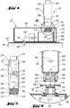
- Figure 1 shows a pump device comprising a housing 106 accommodating a medicament reservoir 101 and a pump mechanism 103 configured to deliver medicament 207 from the medicament reservoir 101 through a fluid connection 104 into a patient's body 99.
- the pump device 10 is fixed to the patient's skin 100 by an adhesive tape 105 arranged at the bottom of the housing 106.
- the bottom of the housing 106 and the adhesive tape 105 have an aperture 107 to allow the fluid connection 104 to go through.
- a connecting element 102 is arranged on the top side of the housing 106 accessible to attach a connector 202 of a filling device 20.
- Figure 2 shows an exemplary embodiment of a filling device 20.
- the filling device 20 has an elongate shape and comprises a housing 203, a trigger assembly 201, a connector 202, and a needle cannula 205 serving as a conduit.
- the housing 203 serves to accommodate a drive unit 206 and a container, e.g. a cartridge 204.
- the cartridge 204 has a piston 211 at one end and a septum (not shown) at the other end.
- the cartridge 204 is preferably filled with a liquid medicament 207.
- the needle cannula 205 has a sharp proximal end 214 suitable to pierce the septum of the cartridge 204.
- the drive unit 206 at least comprises a piston rod 208 to operably engage with the piston 211 of the cartridge 204. Once actuated by trigger assembly 201, the drive unit 206 acts on the piston 211 and medicament 207 contained in the cartridge 204 is expelled through the needle cannula 205.
- the drive unit 206 is preferably implemented all-mechanically and comprises a spring arranged to act on the piston rod 208 once actuated by the trigger 201.
- the spring is a torsion spring or a compression spring.
- other stored energy means such as gas springs or rubber bands, could be used.
- the connector 202 in general, is configured to attach the filling device 20 to a drug reservoir 101 of a pump device 10 via connecting element 102.
- Figure 3 shows the connecting element 102 of the pump device 10 comprising a threading 122 that corresponds to the threading 222 of the connector 202 of the filling device 20.
- the connection may be a bayonet-like, or a snap fit connection.
- the connecting element 102 is shown attached to the reservoir 101.
- the connecting element 102 may be attached to the housing 106 however providing a fluid connection to the reservoir 101.
- the connecting element 102 further comprises a sealing 110 that is pierced by a sharp distal end 215 of needle cannula 205 when the filling device 20 is attached to the medicament reservoir 101 of the pump device 10.
- the sealing is preferably made from rubber material to ensure that after detaching the filling device 20 the medicament reservoir 101 is sealed and protected against intrusion of bacteria, germs, dust, etc. Furthermore, the material is selected to allow multiple times attaching and detaching a filling device 20 to the pump device 10.
- the connector 202 comprises a sleeve 209 that is arranged to permanently extend beyond the distal end 215 of the needle cannula 205 in distal direction (arrow in Fig. 3 ).
- the connector 202 could comprise a movable needle shield arrangement configured to be moveable relative to the needle cannula 205.
- the movable needle shield arrangement is arranged to permanently extend beyond the distal end of the needle cannula 205 in distal direction.
- the pump device 10 In a typical situation of use, a user needs to set up the pump device 10 for infusion of medicament, e.g. insulin.
- the medicament reservoir 101 is empty.
- the filling device 20 has a cartridge 204 filled with the right liquid medicament 207.
- the volume of cartridge 204 corresponds to the volume of the medicament reservoir 101.
- the user would take the filling device 20, attach it to the reservoir 101 and press the trigger 201. Once actuated the drive unit 206 discharges the medicament 207 from the cartridge 204 through the needle cannula 205 into the medicament reservoir 101.
- the pump device 10 is now ready for use. Once the medicament reservoir 101 is empty, the user could take a new filling device 20 to refill the medicament reservoir 101.
- This scenario could help the user to adhere to the filling and set-up procedure.
- Having the same amount of medicament in the cartridge 204 and the medicament reservoir 101 should help preventing under- and/or overfilling. Hence this improves user comfort as well as it helps to prevent waste of medicament.
- the filling device as described above typically is of disposable type. That is to say that after filling the reservoir 101 the filling device 20 is discarded.
- the filling device 20 could be of re-usable type. That is to say that an empty cartridge 204 is replaced by a new cartridge 204 filled with medicament. This would immediately reduce waste. Further, this could help the user to adhere to the filling and set-up procedure.
- the medicament reservoir 101 is filled with medicament in powdered or lyophilized state.
- the lyophilized medicament is inside the reservoir before the filling device 20 is attached to the pump device 10.
- the filling device 20 has a cartridge 204 filled with the right liquid 207, which is a solvent in this situation.
- the volume of cartridge 204 corresponds to the volume of the medicament reservoir 101. The user would take the filling device 20, attach it to the reservoir 101 and press the trigger 201. Once actuated the drive unit 206 discharges the liquid 207, i.e.
- the solvent in this situation from the cartridge 204 through the needle cannula 205 into the medicament reservoir 101.
- the user then detaches the filling device 20 from the pump device10 and may shake the pump device 10 a few times to make sure that the medicament is sufficiently dissolved.
- the pump device 10 is now ready for use.
- This scenario could help the user to adhere to conditions where is it preferred to keep the pharmaceutically active substance in dry form up until before use. Thereby shelf live conditions could be improved.
- the pump device 10 In a further alternative situation of use, a user needs to clean the pump device 10. In a first step the pump device needs to be sterilized before it can be filled with medicament. Alternatively, in a final step the pump device may need to be sterilized after use in order to remove medicament residues. Therefore, the filling device 20 has a cartridge 204 filled with the right liquid 207, which is a sterilizing liquid in this situation.
- This scenario could help the user to adhere to conditions where it is preferred to clean the pump device before and/or after use.
- a further pump device 10' is shown in Figure 4 which relates to another embodiment of a filling device 20' according to the invention.
- the pump device 10' of Figure 4 comprises the elements of the pump device 10 as described before.
- pump device 10' comprises a sensor 120 arranged to determine the fill level of the medicament reservoir 101.
- the pump device 10' further comprises a contact 112 connected to the sensor 120 arranged at the connecting element 102.
- FIG. 5 A further embodiment of a filling device 20' according to the invention is shown in Figure 5 .
- the filling device 20' of Figure 5 comprises the elements known from filling device 20 as described before.
- the filling device 20' further comprises a contact element 212 and a display 210.
- the drive unit 206 of filling device 20' is implemented electromechanically, comprising at least a motor and gear assembly arranged to act on the piston rod 208, a battery 219 to provide power supply, and a controller 220 configured to at least control motor action.
- the controller 220 controls activation of the motor and gear arrangement 206 once actuated by trigger assembly 201.
- the trigger 201 assembly is implemented as a push button.
- the contact element 212 is electrically connected to the controller 220.
- the two devices can communicate via the contact element 212 and contact 112.
- the fill level of the medicament reservoir 101 could be communicated to the controller 220 and the controller 220 commands the drive unit 206 to expel medicament 207 from the cartridge 204 dependent on the signal from the fill level sensor 120.
- Figure 6 provides an enlarged detailed view of front or distal end of filling device 20' comprising the connector 202 comprising sleeve 209 and contact 212. Also, a detailed enlarged view of the pump device 10' is provided showing the connecting element 102 including the sealing 110 and the contact 112. As can be seen, when connector 202 is attached to connecting element 102 contact element 212 is in contact with contact 112. Contact 112 may be biased by a spring 114 to ensure proper connection.
- a user would attach the filling device 20' to the pump device 10' to fill medicament 207 into the reservoir 101.
- the volume of the cartridge 204 does not have to correspond to the volume of the reservoir 101 because the flow of medicament from the cartridge 204 to the reservoir 101 is stopped once the fill level sensor 120 recognizes a certain fill level.
- the conduit 205 is configured to be movable from a first state where it is not in fluid communication with the medicament container 204 to a second state, where it is in fluid communication with the medicament container 204.
- the conduit 205 is implemented as a double ended needle cannula fixed to a moveable hub.
- the hub is biased by a spring.
- the sleeve 209 comprises steps to delimit movement of the needle hub such that the conduit 205 can be moved form the first position against the biasing force of the spring to the second position.
- the medicament 207 is in fluid communication with the conduit 205. Also, the conduit 205 is in fluid communication with the reservoir 101. Thereby it is ensured that the medicament 207 is expelled into the reservoir 101.
- the hub does not abut the connector element 102 and is moved by the force of the springing distal direction and the conduit 205 is moved into the first position.
- the conduit 205 is not in fluid communication with the medicament 207, the medicament 207 in the container 204 is sealed and secured against against intrusion of bacteria, germs, dust, etc. It is to be noted that this embodiment is particularly useful to be implemented in combination with any of the previous embodiments.
Landscapes
- Health & Medical Sciences (AREA)
- Life Sciences & Earth Sciences (AREA)
- Veterinary Medicine (AREA)
- Public Health (AREA)
- General Health & Medical Sciences (AREA)
- Animal Behavior & Ethology (AREA)
- Anesthesiology (AREA)
- Hematology (AREA)
- Heart & Thoracic Surgery (AREA)
- Biomedical Technology (AREA)
- Engineering & Computer Science (AREA)
- Vascular Medicine (AREA)
- Pharmacology & Pharmacy (AREA)
- Infusion, Injection, And Reservoir Apparatuses (AREA)
Claims (15)
- Füllvorrichtung (20') zum Füllen eines Medikamentenreservoirs (101) einer Pumpvorrichtung (10'), wobei die Füllvorrichtung (20') Folgendes aufweist:ein Gehäuse (203), das zum Halten eines Behälters (204) für eine Flüssigkeit (207) ausgestaltet ist, eine Leitung (205), die zum Fluideingriff mit dem Behälter (204) ausgebildet ist,eine Antriebseinheit (206), die dazu ausgestaltet ist, Flüssigkeit (207) durch die Leitung (205) aus dem Behälter (204) auszustoßen, undeinen Verbinder (202), der dazu ausgestaltet ist, an dem Medikamentenreservoir (101) anbringbar zu sein, wobei der Verbinder (202) zumindest ein Kontaktelement (212) aufweist,wobei die Füllvorrichtung (20') ferner eine Auslöseanordnung (201) aufweist, die dazu ausgebildet ist, auf die Antriebseinheit (206) zu wirken, so dass die Flüssigkeit (207) durch die Leitung (205) aus dem Behälter (204) ausgestoßen wird, wenn die Auslöseanordnung aktiviert wird,dadurch gekennzeichnet, dass das zumindest eine Kontaktelement (212) dazu ausgestaltet ist, die Übertragung von Signalen zu und von der Füllvorrichtung (20') zu ermöglichen, und dass die Antriebseinheit (206) von einer Steuerung (220) beim Ausstoßen der Flüssigkeit aus dem Behälter (204) abhängig von einem Signal von einem Sensor (120) der Pumpvorrichtung (10') betätigt wird, so dass die Menge der ausgestoßenen Flüssigkeit an einen Füllstand des Medikamentenreservoirs (101) angepasst ist.
- Füllvorrichtung (20') nach Anspruch 1, wobei der Verbinder (202) eine Hülse (209) aufweist, die so angeordnet ist, dass sie sich permanent über das distale Ende der Leitung (205) hinaus in distaler Richtung erstreckt.
- Füllvorrichtung (20') nach einem der vorhergehenden Ansprüche, wobei die Antriebseinheit (206) ein Energiespeichermittel aufweist, das dazu ausgestaltet ist, Energie zum Ausstoßen des Inhalts aus dem Behälter (204) bereitzustellen, wobei die Auslöseanordnung (201) zur Aktivierung des Energiespeichermittels ausgestaltet ist.
- Füllvorrichtung (20') nach einem der vorhergehenden Ansprüche, wobei die Leitung (205) dazu ausgestaltet ist, aus einem ersten Zustand, in dem sie nicht in Fluidverbindung mit dem Behälter (204) steht, in einen zweiten Zustand, in dem die Leitung (205) in Fluidverbindung mit dem Behälter (204) steht, bewegt zu werden.
- Füllvorrichtung (20') nach einem der vorhergehenden Ansprüche, wobei die Leitung (205) dazu ausgestaltet ist, eine Fluidverbindung mit dem Reservoir (101) herzustellen.
- Füllvorrichtung (20') nach einem der vorhergehenden Ansprüche, wobei das distale Ende der Leitung ein scharfes Ende aufweist, das zum Einstechen in eine Dichtung (110) des Reservoirs (101) ausgestaltet ist.
- Füllvorrichtung (20') nach einem der vorhergehenden Ansprüche, wobei die Hülse (209) dazu ausgestaltet ist, mechanisch mit dem Reservoir (101) verbunden zu werden.
- Füllvorrichtung (20, 20') nach einem der vorhergehenden Ansprüche, wobei die Steuerung (220) dazu ausgestaltet ist, den Betrieb der Antriebseinheit (206) zu steuern, wobei die Steuerung (202) dazu ausgestaltet ist, die Antriebseinheit (206) zu stoppen, so dass keine Flüssigkeit aus dem Behälter (204) ausgestoßen wird.
- Füllvorrichtung (20') nach einem der vorhergehenden Ansprüche, wobei der Verbinder (202) dazu ausgestaltet ist, ein passendes Reservoir (101) zu identifizieren.
- System, aufweisend eine Füllvorrichtung (20') nach einem der vorhergehenden Ansprüche und eine Pumpvorrichtung (10'), wobei die Pumpvorrichtung (10') ein Gehäuse (106), ein Reservoir (101), ein Pumpmittel (103) und einen Verbinder (102) aufweist und wobei der Verbinder (202) der Füllvorrichtung (20') dazu ausgestaltet ist, mechanisch mit dem Verbinder (102) der Pumpvorrichtung (10') verbunden zu werden.
- System nach dem vorhergehenden Anspruch, wobei der Sensor (120) der Pumpvorrichtung (10') dazu ausgestaltet ist, den Füllstand des Reservoirs (101) zu erfassen.
- System nach einem der Ansprüche 10 und 11, wobei, wenn die Füllvorrichtung (20') an der Pumpvorrichtung (10') angebracht ist, der Behälter (204) und das Reservoir (101) durch die Leitung (205) in Fluidverbindung sind.
- System nach einem der Ansprüche 10 bis 12,
wobei, wenn die Auslöseanordnung (201) aktiviert wird, Flüssigkeit (207) mittels der Antriebseinheit (206) aus dem Behälter (204) durch die Leitung (205) in das Reservoir (101) ausgestoßen wird. - System nach einer der Ansprüche 10 bis 13, wobei die Pumpvorrichtung (10') ferner einen mit dem Sensor (120) verbundenen Kontakt (112) aufweist, wobei der Kontakt (112) an dem Verbinder (102) der Pumpvorrichtung (10') angeordnet ist, wobei die Antriebseinheit (206) von der Steuerung (220) beim Ausstoßen von Flüssigkeit (207) aus dem Behälter (204) abhängig von dem Signal von dem Sensor (120) betätigt wird, so dass die Menge an Flüssigkeit (207) an den Füllstand des Reservoirs (101) angepasst ist.
- System nach einem der Ansprüche 10 bis 14, wobei der Verbinder (202) der Füllvorrichtung (20') dazu ausgestaltet ist, eine passende Pumpvorrichtung (10') zu identifizieren.
Priority Applications (1)
| Application Number | Priority Date | Filing Date | Title |
|---|---|---|---|
| EP14713446.4A EP2978470B1 (de) | 2013-03-28 | 2014-03-27 | Füllvorrichtung für eine arzneimittelabgabevorrichtung und system mit einer füllvorrichtung und arzneimittelabgabevorrichtung |
Applications Claiming Priority (3)
| Application Number | Priority Date | Filing Date | Title |
|---|---|---|---|
| EP13161516 | 2013-03-28 | ||
| EP14713446.4A EP2978470B1 (de) | 2013-03-28 | 2014-03-27 | Füllvorrichtung für eine arzneimittelabgabevorrichtung und system mit einer füllvorrichtung und arzneimittelabgabevorrichtung |
| PCT/EP2014/056107 WO2014154777A1 (en) | 2013-03-28 | 2014-03-27 | Filling device for a drug delivery device and system with a fillings device and drug delivery device |
Publications (2)
| Publication Number | Publication Date |
|---|---|
| EP2978470A1 EP2978470A1 (de) | 2016-02-03 |
| EP2978470B1 true EP2978470B1 (de) | 2021-04-28 |
Family
ID=48092693
Family Applications (1)
| Application Number | Title | Priority Date | Filing Date |
|---|---|---|---|
| EP14713446.4A Active EP2978470B1 (de) | 2013-03-28 | 2014-03-27 | Füllvorrichtung für eine arzneimittelabgabevorrichtung und system mit einer füllvorrichtung und arzneimittelabgabevorrichtung |
Country Status (7)
| Country | Link |
|---|---|
| US (1) | US10363367B2 (de) |
| EP (1) | EP2978470B1 (de) |
| JP (1) | JP6419153B2 (de) |
| CN (1) | CN105050638B (de) |
| DK (1) | DK2978470T3 (de) |
| HK (1) | HK1213826A1 (de) |
| WO (1) | WO2014154777A1 (de) |
Families Citing this family (10)
| Publication number | Priority date | Publication date | Assignee | Title |
|---|---|---|---|---|
| GB201505822D0 (en) | 2015-04-03 | 2015-05-20 | Armstrong Gavin | Drinking apparatus for pets |
| HUE056371T2 (hu) * | 2015-11-11 | 2022-02-28 | Hoffmann La Roche | Átömlesztõ eszköz |
| US10661012B2 (en) | 2016-01-04 | 2020-05-26 | Insulet Corporation | Filling assist mechanisms and keyed interfaces for drug delivery devices |
| CN109475467A (zh) * | 2016-09-26 | 2019-03-15 | 泰尔茂株式会社 | 药液填充装置以及药液填充方法 |
| EP3592405A4 (de) * | 2017-03-10 | 2020-11-18 | Enable Injections, Inc. | Rekonstitutionsvorrichtung, system und verfahren |
| HRP20220763T1 (hr) | 2017-07-07 | 2022-09-16 | Neuroderm Ltd | Uređaj za supkutani unos tekućeg medikamenta |
| US20230123806A1 (en) | 2017-07-07 | 2023-04-20 | Neuroderm, Ltd. | Device for subcutaneous delivery of fluid medicament |
| WO2019219564A1 (en) * | 2018-05-15 | 2019-11-21 | Sanofi | Drive unit for a liquid handling device and liquid handling device |
| US11458250B2 (en) | 2018-05-31 | 2022-10-04 | Insulet Corporation | System and techniques for drug reservoir volume detection |
| EP3881875A1 (de) * | 2020-03-20 | 2021-09-22 | Littringer, Eva | Abgabevorrichtung zur abgabe eines arzneimittels |
Citations (1)
| Publication number | Priority date | Publication date | Assignee | Title |
|---|---|---|---|---|
| WO2013016363A2 (en) * | 2011-07-25 | 2013-01-31 | Tandem Diabetes Care, Inc. | Multi-reservoir infusion pump systems and methods |
Family Cites Families (39)
| Publication number | Priority date | Publication date | Assignee | Title |
|---|---|---|---|---|
| US5226896A (en) * | 1990-04-04 | 1993-07-13 | Eli Lilly And Company | Dose indicating injection pen |
| US6293159B1 (en) * | 1995-05-01 | 2001-09-25 | Science Incorporated | Fluid delivery apparatus with reservoir fill assembly |
| US5776103A (en) * | 1995-10-11 | 1998-07-07 | Science Incorporated | Fluid delivery device with bolus injection site |
| US5779676A (en) * | 1995-10-11 | 1998-07-14 | Science Incorporated | Fluid delivery device with bolus injection site |
| US5845600A (en) * | 1998-03-27 | 1998-12-08 | Mendes; Carlos I. | Pet water dispenser with a low water level condition indicator |
| US6062166A (en) * | 1999-02-01 | 2000-05-16 | Macrina; John L. | Pet feeding system |
| US6453927B1 (en) * | 2001-05-16 | 2002-09-24 | International Paper Company | Method and apparatus for precisely dispensing liquids |
| EP2286857A1 (de) * | 2002-07-02 | 2011-02-23 | Panasonic Corporation | Automatische Verabreichungsvorrichtung für medizinische Anwendungen |
| US7637897B2 (en) * | 2004-10-25 | 2009-12-29 | Codman Neuro Sciences Sarl | Implantable pump with integrated refill detection |
| US8444015B2 (en) * | 2005-08-09 | 2013-05-21 | Denis E. Keyes | Fluid dispensing apparatus |
| US7281494B1 (en) * | 2006-03-10 | 2007-10-16 | Connerley Jason A | Pet water supply system |
| US20080035241A1 (en) * | 2006-08-14 | 2008-02-14 | Wittbold Edward H | Multiple function liquid dispenser |
| US7938801B2 (en) * | 2006-11-22 | 2011-05-10 | Calibra Medical, Inc. | Disposable infusion device filling apparatus and method |
| US8226609B2 (en) * | 2007-06-25 | 2012-07-24 | Bioquiddity, Inc. | Fluid dispenser with additive sub-system |
| US8535280B2 (en) * | 2007-09-26 | 2013-09-17 | Medtronic, In | Pressure based refill status monitor for implantable pumps |
| US7918825B2 (en) * | 2007-11-29 | 2011-04-05 | Insulet Corporation | Interfacing a prefilled syringe with an infusion pump to fill the infusion pump |
| US7815609B2 (en) * | 2007-12-19 | 2010-10-19 | Calibra Medical, Inc. | Disposable infusion device positive pressure filling apparatus and method |
| CA3059311A1 (en) * | 2007-12-31 | 2009-07-16 | Deka Products Limited Partnership | Wearable infusion pump assembly |
| DK2300077T3 (en) * | 2008-04-09 | 2017-08-28 | Hoffmann La Roche | MODULAR SKIN ADHESIVE MEDICAL FLUID SYSTEM |
| US8647309B2 (en) * | 2008-05-02 | 2014-02-11 | Sanofi-Aventis Deutschland Gmbh | Medication delivery device |
| KR101251152B1 (ko) | 2008-09-10 | 2013-04-05 | 에프. 호프만-라 로슈 아게 | 치료용 약물과 함께 사용하기 위한 전달 장치 |
| US9421325B2 (en) * | 2008-11-20 | 2016-08-23 | Medtronic, Inc. | Pressure based refill status monitor for implantable pumps |
| DK2258333T3 (da) * | 2009-06-02 | 2012-12-10 | Hoffmann La Roche | Apparat til fyldning af en fleksibel beholder |
| CN201418926Y (zh) * | 2009-06-05 | 2010-03-10 | 李小涛 | 一种组合式贮药注射器 |
| TWI393578B (zh) * | 2009-07-07 | 2013-04-21 | Shl Group Ab | 注射裝置 |
| ATE538771T1 (de) * | 2009-11-06 | 2012-01-15 | Hoffmann La Roche | Vorrichtung zum füllen eines flexiblen vorratsbehälters in einer negativdruckkammer |
| ATE553800T1 (de) * | 2009-11-26 | 2012-05-15 | Hoffmann La Roche | Extern auslösbare kanülenanordnung |
| US8998840B2 (en) * | 2009-12-30 | 2015-04-07 | Medtronic Minimed, Inc. | Connection and alignment systems and methods |
| WO2012019641A1 (en) * | 2010-08-10 | 2012-02-16 | F. Hoffmann-La Roche Ag | Drug reconstitution and delivery device |
| DE102010054883A1 (de) * | 2010-12-17 | 2012-06-21 | Continental Automotive Gmbh | Kraftstoff-Fördereinheit |
| CA3080222C (en) * | 2011-02-09 | 2023-06-13 | Becton, Dickinson And Company | Infusion device with automatic insertion and introducer needle retraction |
| US8708959B2 (en) * | 2011-04-07 | 2014-04-29 | Medtronic, Inc. | Detecting fill status for medical pump reservoir |
| US8795231B2 (en) * | 2011-05-10 | 2014-08-05 | Medtronic Minimed, Inc. | Automated reservoir fill system |
| US20120315163A1 (en) * | 2011-06-13 | 2012-12-13 | Mi Yan | Air-driven hydraulic pump with pressure control |
| CA2839939C (en) * | 2011-06-24 | 2020-07-21 | Saban Ventures Pty Limited | Liquid level sensor |
| US9606641B2 (en) * | 2015-03-09 | 2017-03-28 | Atmel Corporation | Adaptive transmit voltage in active stylus |
| US9134202B2 (en) * | 2012-01-26 | 2015-09-15 | Cryoxtract Instruments, Llc | Robotic end effector for frozen aliquotter and methods of taking a frozen aliquot from biological samples |
| GB2502629B (en) * | 2012-06-01 | 2015-03-11 | Siemens Plc | A closed cryogen cooling system and method for cooling a superconducting magnet |
| US9895488B2 (en) * | 2014-06-27 | 2018-02-20 | Bayer Healthcare Llc | Conductive coding of syringe information |
-
2014
- 2014-03-27 WO PCT/EP2014/056107 patent/WO2014154777A1/en active Application Filing
- 2014-03-27 EP EP14713446.4A patent/EP2978470B1/de active Active
- 2014-03-27 JP JP2016504664A patent/JP6419153B2/ja active Active
- 2014-03-27 US US14/778,581 patent/US10363367B2/en active Active
- 2014-03-27 CN CN201480017898.1A patent/CN105050638B/zh active Active
- 2014-03-27 DK DK14713446.4T patent/DK2978470T3/da active
-
2016
- 2016-02-16 HK HK16101660.9A patent/HK1213826A1/zh unknown
Patent Citations (1)
| Publication number | Priority date | Publication date | Assignee | Title |
|---|---|---|---|---|
| WO2013016363A2 (en) * | 2011-07-25 | 2013-01-31 | Tandem Diabetes Care, Inc. | Multi-reservoir infusion pump systems and methods |
Also Published As
| Publication number | Publication date |
|---|---|
| US20170043090A1 (en) | 2017-02-16 |
| JP6419153B2 (ja) | 2018-11-07 |
| JP2016514523A (ja) | 2016-05-23 |
| WO2014154777A1 (en) | 2014-10-02 |
| HK1213826A1 (zh) | 2016-07-15 |
| US10363367B2 (en) | 2019-07-30 |
| DK2978470T3 (da) | 2021-07-26 |
| EP2978470A1 (de) | 2016-02-03 |
| CN105050638B (zh) | 2020-04-07 |
| CN105050638A (zh) | 2015-11-11 |
Similar Documents
| Publication | Publication Date | Title |
|---|---|---|
| EP2978470B1 (de) | Füllvorrichtung für eine arzneimittelabgabevorrichtung und system mit einer füllvorrichtung und arzneimittelabgabevorrichtung | |
| EP2903669B1 (de) | Medikamentenausgabevorrichtung mit medikamentenabgabestartanzeige | |
| EP3065800B1 (de) | Injektionsvorrichtung | |
| DK3142730T3 (en) | MEDICINAL DISPENSER DEVICE WITH AN ACTIVATION MECHANISM | |
| US11298471B2 (en) | Limiting life time of dispense assembly | |
| US9427527B2 (en) | Fixed-dose medicament delivery device | |
| US20150051545A1 (en) | Medical injection device with injection site pain reduction device | |
| EP2656865A1 (de) | Spritzenträger mit Nadelschutzhülse und Datenspeicher zur Verwendung in medizinischem Auto-Injektor | |
| US10773033B2 (en) | Medicament delivery device with use indicator | |
| DK3142729T3 (en) | ACTIVATION DEVICE FOR MEDICINAL DISPENSER AND MEDICINE DISPENSER. | |
| EP2537546A1 (de) | Medikamentenabgabevorrichtung mit Dosiersteuerungsmechanismus | |
| US20190083713A1 (en) | Drive Mechanism of a Drug Delivery Device Comprising an Accessory Drive | |
| EP3319666B1 (de) | Arzneimittelabgabevorrichtung mit belastungsanzeige | |
| EP2778086A1 (de) | Verpackung für ein Element und Verpackungsanordnung damit | |
| EP2906275B1 (de) | Eine an einer injektionsvorrichtung aufsetzbare nadelvorrichtung mit einer reservoiranordnung mit sperrmechanismus | |
| EP2957308A1 (de) | Kassettenhalter für eine Arzneimittelausgabevorrichtung | |
| US20200276389A1 (en) | A Container for at least a First Injectable Medicament and Injection Device | |
| EP3045185A1 (de) | Konnektor für einen mit einem flüssigen arzneimittel gefüllten behälter |
Legal Events
| Date | Code | Title | Description |
|---|---|---|---|
| PUAI | Public reference made under article 153(3) epc to a published international application that has entered the european phase |
Free format text: ORIGINAL CODE: 0009012 |
|
| 17P | Request for examination filed |
Effective date: 20151028 |
|
| AK | Designated contracting states |
Kind code of ref document: A1 Designated state(s): AL AT BE BG CH CY CZ DE DK EE ES FI FR GB GR HR HU IE IS IT LI LT LU LV MC MK MT NL NO PL PT RO RS SE SI SK SM TR |
|
| AX | Request for extension of the european patent |
Extension state: BA ME |
|
| DAX | Request for extension of the european patent (deleted) | ||
| REG | Reference to a national code |
Ref country code: HK Ref legal event code: DE Ref document number: 1213826 Country of ref document: HK |
|
| STAA | Information on the status of an ep patent application or granted ep patent |
Free format text: STATUS: EXAMINATION IS IN PROGRESS |
|
| 17Q | First examination report despatched |
Effective date: 20180605 |
|
| GRAP | Despatch of communication of intention to grant a patent |
Free format text: ORIGINAL CODE: EPIDOSNIGR1 |
|
| STAA | Information on the status of an ep patent application or granted ep patent |
Free format text: STATUS: GRANT OF PATENT IS INTENDED |
|
| INTG | Intention to grant announced |
Effective date: 20201103 |
|
| GRAJ | Information related to disapproval of communication of intention to grant by the applicant or resumption of examination proceedings by the epo deleted |
Free format text: ORIGINAL CODE: EPIDOSDIGR1 |
|
| STAA | Information on the status of an ep patent application or granted ep patent |
Free format text: STATUS: EXAMINATION IS IN PROGRESS |
|
| GRAP | Despatch of communication of intention to grant a patent |
Free format text: ORIGINAL CODE: EPIDOSNIGR1 |
|
| STAA | Information on the status of an ep patent application or granted ep patent |
Free format text: STATUS: GRANT OF PATENT IS INTENDED |
|
| GRAS | Grant fee paid |
Free format text: ORIGINAL CODE: EPIDOSNIGR3 |
|
| GRAA | (expected) grant |
Free format text: ORIGINAL CODE: 0009210 |
|
| STAA | Information on the status of an ep patent application or granted ep patent |
Free format text: STATUS: THE PATENT HAS BEEN GRANTED |
|
| INTC | Intention to grant announced (deleted) | ||
| INTG | Intention to grant announced |
Effective date: 20210319 |
|
| AK | Designated contracting states |
Kind code of ref document: B1 Designated state(s): AL AT BE BG CH CY CZ DE DK EE ES FI FR GB GR HR HU IE IS IT LI LT LU LV MC MK MT NL NO PL PT RO RS SE SI SK SM TR |
|
| REG | Reference to a national code |
Ref country code: GB Ref legal event code: FG4D |
|
| REG | Reference to a national code |
Ref country code: CH Ref legal event code: EP |
|
| REG | Reference to a national code |
Ref country code: DE Ref legal event code: R096 Ref document number: 602014076965 Country of ref document: DE |
|
| REG | Reference to a national code |
Ref country code: AT Ref legal event code: REF Ref document number: 1386410 Country of ref document: AT Kind code of ref document: T Effective date: 20210515 |
|
| REG | Reference to a national code |
Ref country code: IE Ref legal event code: FG4D |
|
| REG | Reference to a national code |
Ref country code: DK Ref legal event code: T3 Effective date: 20210720 |
|
| REG | Reference to a national code |
Ref country code: LT Ref legal event code: MG9D |
|
| REG | Reference to a national code |
Ref country code: AT Ref legal event code: MK05 Ref document number: 1386410 Country of ref document: AT Kind code of ref document: T Effective date: 20210428 |
|
| PG25 | Lapsed in a contracting state [announced via postgrant information from national office to epo] |
Ref country code: BG Free format text: LAPSE BECAUSE OF FAILURE TO SUBMIT A TRANSLATION OF THE DESCRIPTION OR TO PAY THE FEE WITHIN THE PRESCRIBED TIME-LIMIT Effective date: 20210728 Ref country code: AT Free format text: LAPSE BECAUSE OF FAILURE TO SUBMIT A TRANSLATION OF THE DESCRIPTION OR TO PAY THE FEE WITHIN THE PRESCRIBED TIME-LIMIT Effective date: 20210428 Ref country code: FI Free format text: LAPSE BECAUSE OF FAILURE TO SUBMIT A TRANSLATION OF THE DESCRIPTION OR TO PAY THE FEE WITHIN THE PRESCRIBED TIME-LIMIT Effective date: 20210428 Ref country code: NL Free format text: LAPSE BECAUSE OF FAILURE TO SUBMIT A TRANSLATION OF THE DESCRIPTION OR TO PAY THE FEE WITHIN THE PRESCRIBED TIME-LIMIT Effective date: 20210428 Ref country code: LT Free format text: LAPSE BECAUSE OF FAILURE TO SUBMIT A TRANSLATION OF THE DESCRIPTION OR TO PAY THE FEE WITHIN THE PRESCRIBED TIME-LIMIT Effective date: 20210428 Ref country code: HR Free format text: LAPSE BECAUSE OF FAILURE TO SUBMIT A TRANSLATION OF THE DESCRIPTION OR TO PAY THE FEE WITHIN THE PRESCRIBED TIME-LIMIT Effective date: 20210428 |
|
| PG25 | Lapsed in a contracting state [announced via postgrant information from national office to epo] |
Ref country code: GR Free format text: LAPSE BECAUSE OF FAILURE TO SUBMIT A TRANSLATION OF THE DESCRIPTION OR TO PAY THE FEE WITHIN THE PRESCRIBED TIME-LIMIT Effective date: 20210729 Ref country code: LV Free format text: LAPSE BECAUSE OF FAILURE TO SUBMIT A TRANSLATION OF THE DESCRIPTION OR TO PAY THE FEE WITHIN THE PRESCRIBED TIME-LIMIT Effective date: 20210428 Ref country code: IS Free format text: LAPSE BECAUSE OF FAILURE TO SUBMIT A TRANSLATION OF THE DESCRIPTION OR TO PAY THE FEE WITHIN THE PRESCRIBED TIME-LIMIT Effective date: 20210828 Ref country code: PT Free format text: LAPSE BECAUSE OF FAILURE TO SUBMIT A TRANSLATION OF THE DESCRIPTION OR TO PAY THE FEE WITHIN THE PRESCRIBED TIME-LIMIT Effective date: 20210830 Ref country code: PL Free format text: LAPSE BECAUSE OF FAILURE TO SUBMIT A TRANSLATION OF THE DESCRIPTION OR TO PAY THE FEE WITHIN THE PRESCRIBED TIME-LIMIT Effective date: 20210428 Ref country code: NO Free format text: LAPSE BECAUSE OF FAILURE TO SUBMIT A TRANSLATION OF THE DESCRIPTION OR TO PAY THE FEE WITHIN THE PRESCRIBED TIME-LIMIT Effective date: 20210728 Ref country code: ES Free format text: LAPSE BECAUSE OF FAILURE TO SUBMIT A TRANSLATION OF THE DESCRIPTION OR TO PAY THE FEE WITHIN THE PRESCRIBED TIME-LIMIT Effective date: 20210428 Ref country code: RS Free format text: LAPSE BECAUSE OF FAILURE TO SUBMIT A TRANSLATION OF THE DESCRIPTION OR TO PAY THE FEE WITHIN THE PRESCRIBED TIME-LIMIT Effective date: 20210428 Ref country code: SE Free format text: LAPSE BECAUSE OF FAILURE TO SUBMIT A TRANSLATION OF THE DESCRIPTION OR TO PAY THE FEE WITHIN THE PRESCRIBED TIME-LIMIT Effective date: 20210428 |
|
| REG | Reference to a national code |
Ref country code: NL Ref legal event code: MP Effective date: 20210428 |
|
| PG25 | Lapsed in a contracting state [announced via postgrant information from national office to epo] |
Ref country code: RO Free format text: LAPSE BECAUSE OF FAILURE TO SUBMIT A TRANSLATION OF THE DESCRIPTION OR TO PAY THE FEE WITHIN THE PRESCRIBED TIME-LIMIT Effective date: 20210428 Ref country code: SM Free format text: LAPSE BECAUSE OF FAILURE TO SUBMIT A TRANSLATION OF THE DESCRIPTION OR TO PAY THE FEE WITHIN THE PRESCRIBED TIME-LIMIT Effective date: 20210428 Ref country code: SK Free format text: LAPSE BECAUSE OF FAILURE TO SUBMIT A TRANSLATION OF THE DESCRIPTION OR TO PAY THE FEE WITHIN THE PRESCRIBED TIME-LIMIT Effective date: 20210428 Ref country code: CZ Free format text: LAPSE BECAUSE OF FAILURE TO SUBMIT A TRANSLATION OF THE DESCRIPTION OR TO PAY THE FEE WITHIN THE PRESCRIBED TIME-LIMIT Effective date: 20210428 Ref country code: EE Free format text: LAPSE BECAUSE OF FAILURE TO SUBMIT A TRANSLATION OF THE DESCRIPTION OR TO PAY THE FEE WITHIN THE PRESCRIBED TIME-LIMIT Effective date: 20210428 |
|
| REG | Reference to a national code |
Ref country code: DE Ref legal event code: R097 Ref document number: 602014076965 Country of ref document: DE |
|
| PLBE | No opposition filed within time limit |
Free format text: ORIGINAL CODE: 0009261 |
|
| STAA | Information on the status of an ep patent application or granted ep patent |
Free format text: STATUS: NO OPPOSITION FILED WITHIN TIME LIMIT |
|
| 26N | No opposition filed |
Effective date: 20220131 |
|
| PG25 | Lapsed in a contracting state [announced via postgrant information from national office to epo] |
Ref country code: IS Free format text: LAPSE BECAUSE OF FAILURE TO SUBMIT A TRANSLATION OF THE DESCRIPTION OR TO PAY THE FEE WITHIN THE PRESCRIBED TIME-LIMIT Effective date: 20210828 Ref country code: AL Free format text: LAPSE BECAUSE OF FAILURE TO SUBMIT A TRANSLATION OF THE DESCRIPTION OR TO PAY THE FEE WITHIN THE PRESCRIBED TIME-LIMIT Effective date: 20210428 |
|
| PG25 | Lapsed in a contracting state [announced via postgrant information from national office to epo] |
Ref country code: IT Free format text: LAPSE BECAUSE OF FAILURE TO SUBMIT A TRANSLATION OF THE DESCRIPTION OR TO PAY THE FEE WITHIN THE PRESCRIBED TIME-LIMIT Effective date: 20210428 |
|
| PG25 | Lapsed in a contracting state [announced via postgrant information from national office to epo] |
Ref country code: MC Free format text: LAPSE BECAUSE OF FAILURE TO SUBMIT A TRANSLATION OF THE DESCRIPTION OR TO PAY THE FEE WITHIN THE PRESCRIBED TIME-LIMIT Effective date: 20210428 |
|
| REG | Reference to a national code |
Ref country code: BE Ref legal event code: MM Effective date: 20220331 |
|
| PG25 | Lapsed in a contracting state [announced via postgrant information from national office to epo] |
Ref country code: LU Free format text: LAPSE BECAUSE OF NON-PAYMENT OF DUE FEES Effective date: 20220327 Ref country code: IE Free format text: LAPSE BECAUSE OF NON-PAYMENT OF DUE FEES Effective date: 20220327 |
|
| PG25 | Lapsed in a contracting state [announced via postgrant information from national office to epo] |
Ref country code: BE Free format text: LAPSE BECAUSE OF NON-PAYMENT OF DUE FEES Effective date: 20220331 |
|
| PGFP | Annual fee paid to national office [announced via postgrant information from national office to epo] |
Ref country code: FR Payment date: 20230208 Year of fee payment: 10 Ref country code: DK Payment date: 20230314 Year of fee payment: 10 |
|
| PGFP | Annual fee paid to national office [announced via postgrant information from national office to epo] |
Ref country code: TR Payment date: 20230324 Year of fee payment: 10 |
|
| PGFP | Annual fee paid to national office [announced via postgrant information from national office to epo] |
Ref country code: CH Payment date: 20230401 Year of fee payment: 10 |
|
| PG25 | Lapsed in a contracting state [announced via postgrant information from national office to epo] |
Ref country code: HU Free format text: LAPSE BECAUSE OF FAILURE TO SUBMIT A TRANSLATION OF THE DESCRIPTION OR TO PAY THE FEE WITHIN THE PRESCRIBED TIME-LIMIT; INVALID AB INITIO Effective date: 20140327 |
|
| PG25 | Lapsed in a contracting state [announced via postgrant information from national office to epo] |
Ref country code: MK Free format text: LAPSE BECAUSE OF FAILURE TO SUBMIT A TRANSLATION OF THE DESCRIPTION OR TO PAY THE FEE WITHIN THE PRESCRIBED TIME-LIMIT Effective date: 20210428 Ref country code: CY Free format text: LAPSE BECAUSE OF FAILURE TO SUBMIT A TRANSLATION OF THE DESCRIPTION OR TO PAY THE FEE WITHIN THE PRESCRIBED TIME-LIMIT Effective date: 20210428 |
|
| PGFP | Annual fee paid to national office [announced via postgrant information from national office to epo] |
Ref country code: DE Payment date: 20231229 Year of fee payment: 11 Ref country code: GB Payment date: 20240108 Year of fee payment: 11 |