EP2978209A1 - Apparatus for light intensity adjustment - Google Patents
Apparatus for light intensity adjustment Download PDFInfo
- Publication number
- EP2978209A1 EP2978209A1 EP14178462.9A EP14178462A EP2978209A1 EP 2978209 A1 EP2978209 A1 EP 2978209A1 EP 14178462 A EP14178462 A EP 14178462A EP 2978209 A1 EP2978209 A1 EP 2978209A1
- Authority
- EP
- European Patent Office
- Prior art keywords
- linear polarizing
- polarizing filter
- lens unit
- camera
- actuator
- Prior art date
- Legal status (The legal status is an assumption and is not a legal conclusion. Google has not performed a legal analysis and makes no representation as to the accuracy of the status listed.)
- Granted
Links
Images




Classifications
-
- B—PERFORMING OPERATIONS; TRANSPORTING
- B60—VEHICLES IN GENERAL
- B60R—VEHICLES, VEHICLE FITTINGS, OR VEHICLE PARTS, NOT OTHERWISE PROVIDED FOR
- B60R11/00—Arrangements for holding or mounting articles, not otherwise provided for
- B60R11/04—Mounting of cameras operative during drive; Arrangement of controls thereof relative to the vehicle
-
- H—ELECTRICITY
- H04—ELECTRIC COMMUNICATION TECHNIQUE
- H04N—PICTORIAL COMMUNICATION, e.g. TELEVISION
- H04N23/00—Cameras or camera modules comprising electronic image sensors; Control thereof
- H04N23/50—Constructional details
- H04N23/55—Optical parts specially adapted for electronic image sensors; Mounting thereof
-
- H—ELECTRICITY
- H04—ELECTRIC COMMUNICATION TECHNIQUE
- H04N—PICTORIAL COMMUNICATION, e.g. TELEVISION
- H04N23/00—Cameras or camera modules comprising electronic image sensors; Control thereof
- H04N23/56—Cameras or camera modules comprising electronic image sensors; Control thereof provided with illuminating means
-
- H—ELECTRICITY
- H04—ELECTRIC COMMUNICATION TECHNIQUE
- H04N—PICTORIAL COMMUNICATION, e.g. TELEVISION
- H04N23/00—Cameras or camera modules comprising electronic image sensors; Control thereof
- H04N23/70—Circuitry for compensating brightness variation in the scene
- H04N23/75—Circuitry for compensating brightness variation in the scene by influencing optical camera components
Definitions
- the present invention relates to an apparatus for light intensity adjustment mountable on an automotive camera, comprising at least one first linear polarizing filter, at least one second linear polarizing filter, the first linear polarizing filter and the second polarizing filter are arrangeable in front of a lens unit of an automotive camera such that incident light passes through the at least one first linear polarizing filter and the at least one second linear polarizing filter before entering the lens unit of the automotive camera, and at least one actuator for moving the at least one first linear polarizing filter and/or the at least one second linear polarizing filter with respect to each other such that the intensity of the emergent light is adjustable. Further the present invention relates to an automotive camera with such an apparatus and a vehicle comprising such an automotive camera and/or such an apparatus.
- Cameras are getting increasingly popular for automotive applications: Back-up assist, parking assist, side or interior mirror replacement, mirror blind spot monitoring, lane change assist, to name a few.
- One of the main components of a camera used for these applications is an image sensor.
- the image sensor consists of a plurality of pixels, light sensitive elements that collect incident light projected by the lens unit, and transform it into an electrical signal. This signal can be read out from the pixel and stored, transmitted to the display unit for viewing by a driver, used for object detection or recognition, etc.
- Pixels are read out with the predefined frequency, called frame rate.
- frame rate For most automotive applications an adequate frame rate is in the range of 15 to 60 frames per second (fps).
- Some image sensors allow selection of a frame rate at system start up, however, typically, once selected, the frame rate cannot be changed without re-initialization of the imager.
- a pixel can collect the light between the two consequent read-outs. Thus, for example, if the imager has been initialized to operate at 30 fps, the pixel accumulates the light within 33 ms.
- the lighting conditions under which an automotive camera is supposed to operate can vary significantly: From 1 Lux illumination at night to 20,000 Lux on a sunny day.
- image sensors allow variable integration time while maintaining fixed frame rate. This is achieved by changing time between pixel reset and read out. Whatever charge has been accumulated by the pixel before the reset occurs, it is eliminated.
- This part of the frame period is often referred to as "closed shutter", a term coming from film photography where mechanical shutter was used to adjust exposure time.
- integration time is defined not by the period between two consecutive frames, or in other words, between two consecutive pixel read outs, but by the period between pixel reset and pixel read out instead.
- This part of the frame period is called "open shutter”.
- time between pixel reset and read out is reduced by moving reset as close to read out as necessary. Moving reset towards previous frame read out increases the integration time. Obviously, maximum integration time is limited by the time between two consecutive frames read outs, which in the above example is 33 ms.
- variable integration time causes a new problem, which is often refered to as stroboscopic effect.
- Modem light sources for example light emitting diodes (LED) often illuminate the scene not continuously, but in short pulses instead. This is because the intensity of light cannot be controlled efficiently by changing the voltage; instead pulse width modulation (PWM) is used. In this case the LED is turned on for several milliseconds, and then switched off for another several milliseconds. By changing the ratio between on and off periods, the overall intensity of light can be adjusted.
- PWM pulse width modulation
- some devices require that the light is emitted in short flashes, for example emergency vehicle lighting used to convey to other road users the urgency of their journey, or provide warning of hazard when stationary.
- Strobe lights or LEDs are increasingly popular for those devices. Duration of flashes may be as short as hundreds of microseconds, and their frequency as low as a few Hertz.
- duration of flash emitted by a light source is significantly shorter than the part of frame period corresponding to the open shutter. If the flash occurs when the shutter is closed, the flash cannot be captured by the imager. Thus, the frame in the video stream will appear as if there were no flash at all.
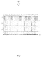
- FIG. 1 is a timing diagram 100, depicting phases of shutter ( Fig. 1a ), light source ( Fig. 1b ) and result of the superposition of the former two ( Fig. 1c ), when the shutter is closed for 1 ms and open for 32 ms.
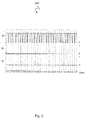
- Fig. 2 is a timing diagram 200, depicting phases of shutter ( Fig. 2a ), light source ( Fig. 2b ) and result of the superposition of the former two ( Fig. 2c ), when the shutter is closed for 11 ms and open for 22 ms.
- Fig. 3 is a timing diagram 300, depicting phases of shutter ( Fig. 3a ), light source ( Fig.
- Fig. 4 is a timing diagram 400, depicting phases of shutter ( Fig. 4a ), light source ( Fig. 4b ) and result of the superposition of the former two ( Fig. 4c ), when the shutter is closed for 15 ms and open for 8 ms.
- the sensor operates at a frame rate of 30 fps, which coresponds to the frame period of approximately 33 ms. Flashes of strobe light occur with the frequency of 5 Hz and have a duration of 1 ms. Thus, within the depicted time span of 1000 ms, 5 flashes occur.
- the upper graph in each figure shows the status of the shutter: highs (denoted as 1) corespond to open shutter, lows (denoted as 0) to a closed one.
- the middle graph shows flashes with highs (denoted as 1) being flash turned on, lows (denoted as 0) off.
- the lower graph Fig. 1c , 2c , 3c , 4c ) represents flashes, captured by the sensor. Obviously, if highs of the upper two graphs coincide, the flash is captured, if not the flash is missed by the sensor.
- Fig. 1 demonstrates, when the shutter is closed for 1 ms and open for 32 ms, all the flashes have been captured.
- Fig. 2 it is suggested that if the shutter stays closed for 11 ms and then open for 22 ms, the very first flash is missing in the resulting graph. Furthermore, if the shutter is closed for 15 ms, and open for 18 ms, as shown in the Fig. 3 , three out of five flashes are missed. In this case, the first captured flash occurs only about 610 ms after start. If the ratio of closed to open shutter changes even more, such as 15 ms to 8 ms, as shown in Fig.
- the integration time In order to avoid a stroboscopic effect, one needs to keep the integration time as close to the time period between two consecutive read outs as possible. I.e. instead of reducing the integration time in the high light conditions, one should artificially reduce the intensity of the light that incidents the imager. In conventional photography, this is achieved by adjusting the diameter of stop inside the lens. The stop diameter is reduced, if the intensity of ambient light increases, and is increased, if the scene gets darker. Thus, the amount of light, accumulated by the pixels, remains within the optimal limits, and the overall image brightness is kept at a reasonable level.
- a problem to be solved by aspects of the invention is to provide a mechanism that allows an automotive camera accurately operating in different lighting conditions.
- an apparatus described at the beginning, enabling adjustment of the emergent light intensity by moving the first linear polarizing filter and/or the second linear polarizing filter with respect to each other is coupled to a frame rate of an image sensor of the an automotive camera by the actuator, in particular such that the integration time of the sensor is maintained at the maximum.. Therefore, an automotive camera including such apparatus can be accurately operated in different lighting conditions.
- the stop integrated into the lens unit may remain fixed.
- the stop mechanism integrated into the lens of the camera further provides highest reliability and durability.
- the apparatus may be mounted on an automotive camera with miniature lens unit without significantly increasing the space, where the automotive camera is mounted.
- the first linear polarizing filter is fixedly secured, and the second linear polarizing filter is moveable by the actuator.
- the first linear polarizing filter is moveable by the actuator, and the second linear polarizing filter is fixedly secured.
- both polarizing filters are moveable by the same at least one actuator, or every linear polarizing filter is moveable by its own actuator.
- three or more polarizing filters fixedly secured or moveable by the same or own actuators, are thinkable.
- the actuator is configured to provide the first orientation of the first and/or the second linear polarizing filters, in case of low-light conditions, in which first orientation both filters polarize the incident light in a same plane.
- the first orientation of the polarizing filters enables an automotive camera operating accurately in low-light conditions.
- the actuator is configured to provide the second orientation of the first and the second linear polarizing filters in case of high-light conditions, in which second orientation polarization planes of both filters are close to be perpendicular to each other.
- the second orientation of the polarizing filters enables an automotive camera operating accurately in high-light conditions.
- the actuator is configured to provide a third orientation of the first and the second linear polarizing filters in case of intermediate-light conditions, in which third orientation lies between the first orientation and the second orientation of the linear polarizing filters.
- the third orientation of the polarizing filters enables an automotive camera operating accurately in intermediate-light conditions.
- the first linear polarizing filter is fixedly mountable in front of the lens unit, and the second linear polarizing filter is movable with respect to the first linear polarizing filter.
- the camera can be accurately operated under different lighting conditions.
- Such an apparatus allows avoiding stroboscopic effects.
- the actuator is configured to rotate the second linear polarizing filter about a rotation axis, in particular by at least 90 degrees.
- the second linear polarizing filter By rotating the second linear polarizing filter about a rotation axis, in particular by at least 90 degrees, light exposure of the image sensor can be effectively controlled in the entire range of possible lighting conditions..
- the rotation axis of the moveable filter approximately coincides with an optical axis of the lens unit, when the apparatus is mounted on the camera.
- the apparatus comprises an inner ring carrying the second linear polarizing filter, and an outer ring carrying the first linear polarizing filter, wherein both the inner ring and the outer ring are aligned with the optical axis of the lens unit, when the apparatus is mounted on the camera.
- an arrangement is easy to manufacture and requires only a small space.
- a position sensor for sensing the position of the filters becomes redundant. Instead, an algorithm for finding optimum orientation of the filters by measuring the image brightness can be applied.
- the actuator comprises a worm wheel configured to move the inner ring.
- a worm wheel configured to move the inner ring.
- the rotation axis of the moveable polarizing filter is approximately parallel to an optical axis of the lens unit, when the apparatus is mounted on the camera.
- the rotation mechanism is simplified. In particular a worm wheel is not required. This simplifies the integration and reduces the costs of the device while increasing its robustness.
- the first linear polarizing filter is approximately formed as a circle having a center, coinciding with the optical axis of the lens unit, when the apparatus is mounted on the camera, and the second linear polarizing filter is approximately formed as a semi circle, having a center, coinciding with the rotation axis of the actuator.
- a circle and a semi circle are easy to manufacture, and provide sufficient overlapping area where a light intensity can be adjusted.
- an automotive camera comprising: at least one lens unit and at least one image sensor, comprising a plurality of light sensitive elements, configured to collect incident light, projected by the lens unit, and transform it into an electrical signal, wherein the image sensor is configured to read out the charge, collected by the plurality of light sensitive elements, with a predetermined frame rate.
- the automotive camera comprises further at least one apparatus for light intensity adjustment, in particular, having one or more of the features described before, which is mounted or mountable in front of the lens unit.
- the apparatus for light intensity adjustment in front of the lens unit enables maintaining miniature size of the camera that is required for automotive applications.There is no need to adjust the stop mechanism, integrated into the lens unit of the camera. Thus, the stop mechanism, integrated into the lens of the camera, further provides highest reliability and durability. An automotive camera including such an apparatus can be accurately operated in different lighting conditions.
- integration time of the image sensor for collecting the incident light is approximately constant and is close to the frame period. That provides precise image sensing and avoids the stroboscopic effect, as no events, such as flashes, can get lost.
- a vehicle comprising at least one automotive camera, in particular, as described above, and/or at least one apparatus, in particular as described above.
- the driver will be able to see daylights of overtaking vehicles.
- the driver's ability to adequately and in time react on the road situation will be significantly increased, thereby reducing accidents.
- the problem is further solved by an apparatus for adjustment of light intensity that incidents a lens and a sensor, such that a pair of polarizing filters is placed on the optical path outside of the lens, and at least one of the filters is moveable.
- an apparatus for adjustment of light intensity that incidents a lens and a sensor, such that a pair of polarizing filters is placed on the optical path outside of the lens, and at least one of the filters is moveable.
- the problem is further solved by a camera mounted on a vehicle, such that the amount of incident light is adjusted by the apparatus for adjustment of an intensity of light.
- a camera mounted on a vehicle, such that the amount of incident light is adjusted by the apparatus for adjustment of an intensity of light.
- Such a camera may accurately operate in different lighting conditions.
- the integration time of the sensor is kept reasonably constant and close to the maximum defined by the time period between two consecutive frame read outs. By using such integration time, no events will be missed by the camera.
- the problem is solved by a method for operating an apparatus for light intensity adjustment, mounted on an automotive camera, comprising a lens unit and an image sensor, comprising a plurality of light sensitive elements, configured to collect incident light, projected by the lens unit and transform it into an electrical signal, wherein the image sensor is configured to read out the charge, collected by the plurality of light sensitive elements with a predetermined frame rate, the apparatus comprising a first and a second linear polarizing filter, arranged in front of the lens unit such that the incident light passes through both of them before entering the lens unit, the method comprising: adapting a light exposure of the image sensor to the frame rate of the image sensor and lighting conditions by moving the first and the second linear polarizing filters with respect to each other.
- the problem is further solved by a computer program with a program code for performing the above-described method, when the computer program runs on a computer.
- the apparatus can be used for controlling amount of light that reaches an image sensor, also denoted as imager of the camera.
- the apparatus comprises two polarizer filters, one of which may move with respect to another in such a way, that the amount of transmitted light is gradually changed. This allows keeping image sensor integration time close to the frame period, thus eliminating stroboscopic effect, when dealing with light emission diode (LED) based daytime running lamps, installed on a vehicle or strobe lights of emergency lighting.
- LED light emission diode
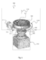
- Fig. 5 is a lateral view of an apparatus for light intensity adjustment 500 in a three-dimensional representation according to an implementation form
- Fig. 6 illustrates an exploded view of the apparatus 500, depicted in Fig. 5
- the apparatus 500 includes a first 501 and a second 503 linear polarizing filter and an actuator 511.
- the apparatus for light intensity adjustment 500 is mountable on an automotive camera 519.
- Such an automotive camera 519 may include a lens unit 509 and an image sensor (not depicted in Fig. 5 ), comprising a plurality of light sensitive elements, configured to collect incident light projected by the lens unit 509, and transform it into an electrical signal.
- the image sensor may read out the charge collected by the plurality of light sensitive elements with a predetermined frame rate.
- the first 501 and the second 503 linear polarizing filters are arrangeable in front of the lens unit 509, such that the incident light passes through both of them before entering the lens unit 509.
- the actuator 511 can move the first 501 and the second 503 linear polarizing filters with respect to each other. By that movement the actuator 511 adapts a light exposure of the image sensor to the frame rate of the image sensor and lighting conditions, when the apparatus 500 is mounted on the automotive camera 519 as depicted in Fig. 5 .
- the apparatus 500 can be mounted on the camera 519 and can be released from the camera 519. While Fig. 5 depicts an automotive camera 519, the apparatus can also be mounted on other kinds of cameras or optical systems, for example iris, telescope, glasses etc.
- the size of the apparatus may be fitted to a size of the optical system, whereon the apparatus is mounted.
- the actuator 511 can provide a first orientation 515a of the first 501 and the second 503 linear polarizing filters in case of low-light conditions. In that first orientation 515a both filters 501, 503 polarize the incident light in a same plane.
- the actuator 511 can provide a second orientation 515b of the first 501 and the second 503 linear polarizing filters in case of high-light conditions. In that second orientation 515b polarization planes of both filters 501, 503 are close to be perpendicular to each other.
- the actuator 511 can provide a third orientation 515c of the first 501 and the second 503 linear polarizing filters in case of intermediate-light conditions.
- That third orientation 515c lies in between the first orientation 515a and the second orientation 515b of the linear polarizing filters 501, 503.
- the first orientation 515a may be a first angle
- the second orientation 515b may be a second angle
- the third orientation 515c may be a third angle in between the first angle and the second angle.
- the first linear polarizing filter 501 may be fixedly mountable in front of the lens unit 509
- the second linear polarizing filter 503 may be movable with respect to the first linear polarizing filter 501 or vice versa.
- the actuator 511 may rotate the second linear polarizing filter 503 about a rotation axis 516, in particular by at least 90 degrees.
- the rotation axis 516 may approximately coincide with an optical axis of the lens unit 509, when the apparatus is mounted on the camera 519 as shown in Fig. 5 .
- the apparatus 500 may include an inner ring 507, carrying the second linear polarizing filter 503, and an outer ring 505, carrying the first linear polarizing filter 501. Both, the inner ring 507 and the outer ring 505 may be aligned with the optical axis of the lens unit 509, when the apparatus 500, 600 is mounted on the camera 519.
- the actuator 511 may include a worm wheel 513 for moving the inner ring 507.
- the automotive camera 519 may include a lens unit 509 and an image sensor, comprising a plurality of light sensitive elements, which collect incident light, projected by the lens unit 509 and transform it into an electrical signal.
- the image sensor may read out the charge collected by the plurality of light sensitive elements with a predetermined frame rate.
- Fig. 5 shows the apparatus 500, mounted on the automotive camera 519. Integration time of the image sensor for collecting the incident light may be approximately constant. The integration time of the image sensor may be close to a maximum, defined by a time period between two conscecutive frame read outs.
- One or more of the automotive cameras 519 together with mounted apparatus 500, 600 may be mounted on a vehicle (not depicted in the figures).
- the apparatus for light intensity adjustment 500, 600 may be mounted outside of the lens unit 509 that may have a fixed stop diameter, for example in front of the first lens element.
- the apparatus 500 may include a pair of linear polarizing filters 501, 503, one of which may be fixed in a housing, and another can be rotated by at least 90 degrees.
- the optical surfaces of the filters 501, 503 may be approximately parallel to each other.
- the filters 501, 503 may be situated in the housing in such a way that the incident light passes through both of them before it enters the front optical element of the lens unit 509.
- the moveable filter, in Figs. 5 and 6 the second linear polarizing filter 503 may be rotated by the actuator 511.
- the orientation of the filters 501, 503 is such that they polarize the incident light in the same plane, a maximum of the incident light may reach the lens unit 509 and the sensor. This would be the case in the low-light conditions.
- polarizing planes of the filters 501, 503 are close to be perpendicular to each other, only a small portion of the incident light reaches the lens and the sensor. This would correspond to the high-light conditions.
- Orientations of the filter polarizing planes between the two extremes described above correspond to intermediate lighting conditions.
- the axis of rotation 516 of the moveable filter 503 may coincide with the optical axis of the lens 509.
- the camera 519 with the lens 509, actuator 511 and the outer ring 505 of the bearing may be mounted in the device housing.
- the actuator shaft may feature a worm that may be in contact with the worm wheel 513, thus making up a worm gear arrangement.
- the worm wheel 513 may be firmly attached to the inner ring 507 of the bearing.
- the stationary polarizer 501 may be attached to the outer ring 505 of the bearing, and the moving polarizer, i.e. the second polarizing filter 503 to the worm wheel 513.
- a torque from the actuator's rotor may be transferred to the worm, which in turn, rotates the worm wheel 513 with the attached polarizer 503 and the inner ring 507 of the bearing.
- An advantage of such an apparatus 500, 600 is that a position sensor, which is typically used to determine the position of moving parts of the mechanism, is not required.
- the position sensor can be replaced by an algorithm that calibrates the system at the start-up by finding the position where the light intensity is at a maximum (or minimum, respectively). Measurement of the amount of light may be performed by the imager. Once a peak position has been found, other required polarizer positions can be set by counting steps of the stepper motor of the actuator 511.
- the stationary outer polarizer i.e. the first polarizing filter 501 may be equipped with an electrical heater that may be activated manually or automatically, e.g. whenever frost, snow or moisture obscures the view for the camara. This allows eliminating an additional cover glass that is typically placed in front of the lens to protect it from dirt, moisture and frost.
- the logic responsible for the pixel integration time adjustment may be eliminated from the imager or supporting integrated circuit, in order to simplify its layout, thus reducing silicon area required for logic implementation and eventually save costs.
- pixel integration time may be fixed at the level reasonably close to the frame period.
- Exposure adjustment may be achieved by changing the intensity of incident light with the use of the two polarizers 501, 503.
- Fig. 7 is a lateral view of an apparatus for light intensity adjustment 700 in a three-dimensional representation according to an implementation form.
- the apparatus 700 includes a first 701 and a second 703 linear polarizing filter and an actuator 711.
- the apparatus for light intensity adjustment 700 is mountable on an automotive camera 519 as described above with respect to Figs. 5 and 6 .
- the first 701 and the second 703 linear polarizing filters are arrangeable in front of the lens unit 509 such that the incident light passes through both of them 701, 703 before entering the lens unit 509.
- the actuator 711 can move the first 701 and the second 703 linear polarizing filters with respect to each other.
- the actuator 711 adapts a light exposure of the image sensor to the frame rate of the image sensor and lighting conditions, when the apparatus 700 is mounted on the automotive camera 719 as depicted in Fig. 7 .
- the apparatus 700 can be mounted on the camera 519 and can be released from the camera 519. While Fig. 7 depicts an automotive camera 519, the apparatus can also be mounted on other kinds of cameras or optical systems, for example iris, telescope, glasses etc. A size of the apparatus may be fitted to a size of the optical system, whereon the apparatus is mounted.
- the actuator 711 can provide a first orientation 715a of the first 701 and the second 703 linear polarizing filters in case of low-light conditions. In that first orientation 715a both filters 701, 703 polarize the incident light in a same plane.
- the actuator 711 can provide a second orientation 715b of the first 701 and the second 703 linear polarizing filters in case of high-light conditions. In that second orientation 715b polarization planes of both filters 701, 703 are close to be perpendicular to each other.
- the actuator 711 can provide a third orientation 715c of the first 701 and the second 703 linear polarizing filters in case of intermediate-light conditions.
- That third orientation 715c lies in between the first orientation 715a and the second orientation 715b of the linear polarizing filters 701, 703.
- the first orientation 715a may be a first angle
- the second orientation 715b may be a second angle
- the third orientation 715c may be a third angle in between the first angle and the second angle.
- the first linear polarizing filter 701 may be fixedly mountable in front of the lens unit 509
- the second linear polarizing filter 703 may be movable with respect to the first linear polarizing filter 701 or vice versa.
- the actuator 711 may rotate the second linear polarizing filter 703 by a rotation axis 716, in particular by at least 90 degrees.
- the rotation axis 718 may be approximately parallel to an optical axis 716 of the lens unit 509, when the apparatus is mounted on the camera 519 as shown in Fig. 7 .
- the first linear polarizing filter 701 may be approximately formed as a circle (or as a polygon having n edges), having a center coinciding with the optical axis 716 of the lens unit 509, when the apparatus is mounted on the camera.
- the second linear polarizing filter 703 may be approximately formed as a semi circle (or as a semi polygon having n/2 edges), having a center coinciding with the rotation axis 718 of the actuator 711. Other geometrical shapes of both filters 701, 703 may be applied as well.
- the apparatus 700 may include an inner semi ring 707, carrying the second linear polarizing filter 703, and an outer ring 705, carrying the first linear polarizing filter 701.
- the inner semi ring 707 may be aligned with a rotation axis 718 of the actuator 711.
- the outer ring 705 may be aligned with the optical axis 716 of the lens unit 509, when the apparatus 700 is mounted on the camera 519 as depicted in Fig. 7 .
- the rotation axis 718 of the actuator 711 may drive the inner semi ring 707.
- An area of the inner semi ring 707 may be larger than an area of the outer ring 705.
- One or more of the automotive cameras 519 together with mounted apparatus 700 may be mounted on a vehicle (not depicted in the figures).
- the apparatus for light intensity adjustment 700 may be mounted outside of the lens unit 509 that may have a fixed stop diameter, for example in front of the first lens element.
- the apparatus 700 may include a pair of linear polarizing filters 701, 703, one of which may be fixed in a housing, and another can be rotated by at least 90 degrees.
- the optical surfaces of the filters 701, 703 may be approximately parallel to each other.
- the filters 701, 703 may be situated in the housing in such a way that the incident light passes through both of them before it enters the front optical element of the lens unit 709.
- the moveable filter, in Fig. 7 the second linear polarizing filter 703 may be rotated by the actuator 711.
- the filters 701, 703 Whenever the orientation of the filters 701, 703 is such that they polarize the incident light in the same plane, a maximum of the incident light may reach the lens unit 509 and the sensor. This would be the case in the low-light conditions. Whenever polarizing planes of the filters 701, 703 are close to be perpendicular to each other, only a small portion of the incident light reaches the lens and the sensor. This would correspond to the high-light conditions. Orientations of the filter polarizing planes between the two extremes described above correspond to intermediate lighting conditions.
- the axis of rotation 718 of the moveable filter i.e. the second polarizing filter 703 may not coincide with the optical axis 716 of the lens unit 709 as depicted in Fig. 7 .
- the rotation mechanism can be simplified, thus simplifying the integration and reducing the costs of the device while increasing its robustness.
- the stationary outer polarizer i.e. the first polarizing filter 701 may be equipped with an electrical heater as described above with respect to Fig. 5 .
- the logic responsible for the pixel integration time adjustment may be eliminated from the imager or supporting integrated circuit as described above with respect to Fig. 5 .
Landscapes
- Engineering & Computer Science (AREA)
- Multimedia (AREA)
- Signal Processing (AREA)
- Mechanical Engineering (AREA)
- Studio Devices (AREA)
- Blocking Light For Cameras (AREA)
Abstract
Description
- The present invention relates to an apparatus for light intensity adjustment mountable on an automotive camera, comprising at least one first linear polarizing filter, at least one second linear polarizing filter, the first linear polarizing filter and the second polarizing filter are arrangeable in front of a lens unit of an automotive camera such that incident light passes through the at least one first linear polarizing filter and the at least one second linear polarizing filter before entering the lens unit of the automotive camera, and at least one actuator for moving the at least one first linear polarizing filter and/or the at least one second linear polarizing filter with respect to each other such that the intensity of the emergent light is adjustable. Further the present invention relates to an automotive camera with such an apparatus and a vehicle comprising such an automotive camera and/or such an apparatus.
- Cameras are getting increasingly popular for automotive applications: Back-up assist, parking assist, side or interior mirror replacement, mirror blind spot monitoring, lane change assist, to name a few. One of the main components of a camera used for these applications is an image sensor. The image sensor consists of a plurality of pixels, light sensitive elements that collect incident light projected by the lens unit, and transform it into an electrical signal. This signal can be read out from the pixel and stored, transmitted to the display unit for viewing by a driver, used for object detection or recognition, etc.
- Pixels are read out with the predefined frequency, called frame rate. For most automotive applications an adequate frame rate is in the range of 15 to 60 frames per second (fps). Some image sensors allow selection of a frame rate at system start up, however, typically, once selected, the frame rate cannot be changed without re-initialization of the imager. Theoretically, a pixel can collect the light between the two consequent read-outs. Thus, for example, if the imager has been initialized to operate at 30 fps, the pixel accumulates the light within 33 ms. However, the lighting conditions under which an automotive camera is supposed to operate, can vary significantly: From 1 Lux illumination at night to 20,000 Lux on a sunny day. And while for low light conditions 33 ms integration time might be adequate, it may be too long for high light conditions. In this case the pixel will be overexposed, i.e., the electrical signal output by the pixel will be driven to its maximum regardless of small variations in object brightness.
- In order to overcome this problem, image sensors allow variable integration time while maintaining fixed frame rate. This is achieved by changing time between pixel reset and read out. Whatever charge has been accumulated by the pixel before the reset occurs, it is eliminated. This part of the frame period is often referred to as "closed shutter", a term coming from film photography where mechanical shutter was used to adjust exposure time. Thus, integration time is defined not by the period between two consecutive frames, or in other words, between two consecutive pixel read outs, but by the period between pixel reset and pixel read out instead. This part of the frame period is called "open shutter". In order to reduce the amount of light transformed into electrical signal, time between pixel reset and read out is reduced by moving reset as close to read out as necessary. Moving reset towards previous frame read out increases the integration time. Obviously, maximum integration time is limited by the time between two consecutive frames read outs, which in the above example is 33 ms.
- However, while solving the problem of imager adaptation to different lighting conditions, variable integration time causes a new problem, which is often refered to as stroboscopic effect. Modem light sources, for example light emitting diodes (LED) often illuminate the scene not continuously, but in short pulses instead. This is because the intensity of light cannot be controlled efficiently by changing the voltage; instead pulse width modulation (PWM) is used. In this case the LED is turned on for several milliseconds, and then switched off for another several milliseconds. By changing the ratio between on and off periods, the overall intensity of light can be adjusted.
- Moreover, some devices require that the light is emitted in short flashes, for example emergency vehicle lighting used to convey to other road users the urgency of their journey, or provide warning of hazard when stationary. Strobe lights or LEDs are increasingly popular for those devices. Duration of flashes may be as short as hundreds of microseconds, and their frequency as low as a few Hertz.
- In these cases duration of flash emitted by a light source is significantly shorter than the part of frame period corresponding to the open shutter. If the flash occurs when the shutter is closed, the flash cannot be captured by the imager. Thus, the frame in the video stream will appear as if there were no flash at all.
-
Figures 1 to 4 illustrate how shutter timing influences the severity of the effect.Fig. 1 is a timing diagram 100, depicting phases of shutter (Fig. 1a ), light source (Fig. 1b ) and result of the superposition of the former two (Fig. 1c ), when the shutter is closed for 1 ms and open for 32 ms.Fig. 2 is a timing diagram 200, depicting phases of shutter (Fig. 2a ), light source (Fig. 2b ) and result of the superposition of the former two (Fig. 2c ), when the shutter is closed for 11 ms and open for 22 ms.Fig. 3 is a timing diagram 300, depicting phases of shutter (Fig. 3a ), light source (Fig. 3b ) and result of the superposition of the former two (Fig. 3c ), when the shutter is closed for 15 ms and open for 18 ms.Fig. 4 is a timing diagram 400, depicting phases of shutter (Fig. 4a ), light source (Fig. 4b ) and result of the superposition of the former two (Fig. 4c ), when the shutter is closed for 15 ms and open for 8 ms. In these examples, the sensor operates at a frame rate of 30 fps, which coresponds to the frame period of approximately 33 ms. Flashes of strobe light occur with the frequency of 5 Hz and have a duration of 1 ms. Thus, within the depicted time span of 1000 ms, 5 flashes occur. The upper graph in each figure (Fig. 1a ,2a ,3a ,4a ) shows the status of the shutter: highs (denoted as 1) corespond to open shutter, lows (denoted as 0) to a closed one. The middle graph (Fig. 1b ,2b ,3b ,4b ) shows flashes with highs (denoted as 1) being flash turned on, lows (denoted as 0) off. And finally, the lower graph (Fig. 1c ,2c ,3c ,4c ) represents flashes, captured by the sensor. Obviously, if highs of the upper two graphs coincide, the flash is captured, if not the flash is missed by the sensor. - As
Fig. 1 demonstrates, when the shutter is closed for 1 ms and open for 32 ms, all the flashes have been captured. InFig. 2 , it is suggested that if the shutter stays closed for 11 ms and then open for 22 ms, the very first flash is missing in the resulting graph. Furthermore, if the shutter is closed for 15 ms, and open for 18 ms, as shown in theFig. 3 , three out of five flashes are missed. In this case, the first captured flash occurs only about 610 ms after start. If the ratio of closed to open shutter changes even more, such as 15 ms to 8 ms, as shown inFig. 4 , none of the flashes occurred within 1000 ms from the start is captured by the sensor. The situation, depicted inFig. 4 , may cause safety problems for the driver. For example, emergency lighting will appear switched off on the display. Similarly, the driver will not be able to see with the mirror replacing camera LED day lights of the overtaking vehicles. This may reduce the driver's ability to react on the road situation adequately and in time, and thus may result in a road accident. - In order to avoid a stroboscopic effect, one needs to keep the integration time as close to the time period between two consecutive read outs as possible. I.e. instead of reducing the integration time in the high light conditions, one should artificially reduce the intensity of the light that incidents the imager. In conventional photography, this is achieved by adjusting the diameter of stop inside the lens. The stop diameter is reduced, if the intensity of ambient light increases, and is increased, if the scene gets darker. Thus, the amount of light, accumulated by the pixels, remains within the optimal limits, and the overall image brightness is kept at a reasonable level.
- However, mechanical stop mechanisms, integrated into the lenses, common in conventional photography are hardly applicable to the lenses, used in automotive cameras. First of all, automotive applications require highest reliability and durability of the stop mechanism. Secondly, the space, where the automotive camera is mounted, is typically very limited by the design of the surrounding components. This requires that the lens remains relatively miniature; usually, the largest outer diameter of the lens does not exceed 20 mm. Building into such a miniature lens a highly reliable and durable stop mechanism that includes an actuator, is an extremely challenging task. Apart from that, such a lens with adjustable stop diameter would be significantly more expensive than a similar lens with a fixed stop diameter.
- A problem to be solved by aspects of the invention is to provide a mechanism that allows an automotive camera accurately operating in different lighting conditions.
- The problem is solved by an apparatus, described at the beginning, enabling adjustment of the emergent light intensity by moving the first linear polarizing filter and/or the second linear polarizing filter with respect to each other is coupled to a frame rate of an image sensor of the an automotive camera by the actuator, in particular such that the integration time of the sensor is maintained at the maximum.. Therefore, an automotive camera including such apparatus can be accurately operated in different lighting conditions.
- Mounting such an apparatus for light intensity adjustment on an automotive camera, eliminates the need of changing the design of the lens unit, in particular the stop integrated into the lens unit may remain fixed. Thus, the stop mechanism integrated into the lens of the camera further provides highest reliability and durability. The apparatus may be mounted on an automotive camera with miniature lens unit without significantly increasing the space, where the automotive camera is mounted.
- In one embodiment of the apparatus, the first linear polarizing filter is fixedly secured, and the second linear polarizing filter is moveable by the actuator. In the further embodiment, the first linear polarizing filter is moveable by the actuator, and the second linear polarizing filter is fixedly secured. In a further embodiment, both polarizing filters are moveable by the same at least one actuator, or every linear polarizing filter is moveable by its own actuator.
- In further embodiments, three or more polarizing filters, fixedly secured or moveable by the same or own actuators, are thinkable.
- According to an implementation form of the apparatus, the actuator is configured to provide the first orientation of the first and/or the second linear polarizing filters, in case of low-light conditions, in which first orientation both filters polarize the incident light in a same plane. The first orientation of the polarizing filters enables an automotive camera operating accurately in low-light conditions.
- According to an implementation form of the apparatus, the actuator is configured to provide the second orientation of the first and the second linear polarizing filters in case of high-light conditions, in which second orientation polarization planes of both filters are close to be perpendicular to each other. The second orientation of the polarizing filters enables an automotive camera operating accurately in high-light conditions.
- According to an implementation form of the apparatus, the actuator is configured to provide a third orientation of the first and the second linear polarizing filters in case of intermediate-light conditions, in which third orientation lies between the first orientation and the second orientation of the linear polarizing filters. The third orientation of the polarizing filters enables an automotive camera operating accurately in intermediate-light conditions.
- According to an implementation form of the apparatus, the first linear polarizing filter is fixedly mountable in front of the lens unit, and the second linear polarizing filter is movable with respect to the first linear polarizing filter. By moving the second linear polarizing filter with respect to the first linear polarizing filter, the camera can be accurately operated under different lighting conditions. Such an apparatus allows avoiding stroboscopic effects.
- According to an implementation form of the apparatus, the actuator is configured to rotate the second linear polarizing filter about a rotation axis, in particular by at least 90 degrees. By rotating the second linear polarizing filter about a rotation axis, in particular by at least 90 degrees, light exposure of the image sensor can be effectively controlled in the entire range of possible lighting conditions..
- According to an implementation form of the apparatus, the rotation axis of the moveable filter approximately coincides with an optical axis of the lens unit, when the apparatus is mounted on the camera. Such an arrangement enables minimizing the form factor of the device.
- According to an implementation form the apparatus, the apparatus comprises an inner ring carrying the second linear polarizing filter, and an outer ring carrying the first linear polarizing filter, wherein both the inner ring and the outer ring are aligned with the optical axis of the lens unit, when the apparatus is mounted on the camera. Such an arrangement is easy to manufacture and requires only a small space. Besides, a position sensor for sensing the position of the filters becomes redundant. Instead, an algorithm for finding optimum orientation of the filters by measuring the image brightness can be applied.
- According to an implementation form of the apparatus, the actuator comprises a worm wheel configured to move the inner ring. Such a worm wheel is compact, robust in implementation, and prevents unintentional rotation of the inner ring due to vibrations or mechanical impact.
- According to an implementation form of the apparatus, the rotation axis of the moveable polarizing filter is approximately parallel to an optical axis of the lens unit, when the apparatus is mounted on the camera. By shifting the axis of rotation to be parallel to the optical axis of the lens unit such, that it is outside of the outer diameter of the lens unit, the rotation mechanism is simplified. In particular a worm wheel is not required. This simplifies the integration and reduces the costs of the device while increasing its robustness.
- According to an implementation form of the apparatus, the first linear polarizing filter is approximately formed as a circle having a center, coinciding with the optical axis of the lens unit, when the apparatus is mounted on the camera, and the second linear polarizing filter is approximately formed as a semi circle, having a center, coinciding with the rotation axis of the actuator. Such a circle and a semi circle are easy to manufacture, and provide sufficient overlapping area where a light intensity can be adjusted.
- The problem is further solved by an automotive camera, comprising: at least one lens unit and at least one image sensor, comprising a plurality of light sensitive elements, configured to collect incident light, projected by the lens unit, and transform it into an electrical signal, wherein the image sensor is configured to read out the charge, collected by the plurality of light sensitive elements, with a predetermined frame rate. The automotive camera comprises further at least one apparatus for light intensity adjustment, in particular, having one or more of the features described before, which is mounted or mountable in front of the lens unit.
- Mounting the apparatus for light intensity adjustment in front of the lens unit enables maintaining miniature size of the camera that is required for automotive applications.There is no need to adjust the stop mechanism, integrated into the lens unit of the camera. Thus, the stop mechanism, integrated into the lens of the camera, further provides highest reliability and durability. An automotive camera including such an apparatus can be accurately operated in different lighting conditions.
- According to an implementation form of the automotive camera, integration time of the image sensor for collecting the incident light is approximately constant and is close to the frame period. That provides precise image sensing and avoids the stroboscopic effect, as no events, such as flashes, can get lost.
- The problem is further solved by a vehicle, comprising at least one automotive camera, in particular, as described above, and/or at least one apparatus, in particular as described above. In such a vehicle the driver will be able to see daylights of overtaking vehicles. The driver's ability to adequately and in time react on the road situation will be significantly increased, thereby reducing accidents.
- The problem is further solved by an apparatus for adjustment of light intensity that incidents a lens and a sensor, such that a pair of polarizing filters is placed on the optical path outside of the lens, and at least one of the filters is moveable. Such an apparatus allows an automotive camera accurately operating in different lighting conditions.
- The problem is further solved by a camera mounted on a vehicle, such that the amount of incident light is adjusted by the apparatus for adjustment of an intensity of light. Such a camera may accurately operate in different lighting conditions.
- According to an implementation form of the camera, the integration time of the sensor is kept reasonably constant and close to the maximum defined by the time period between two consecutive frame read outs. By using such integration time, no events will be missed by the camera.
- The problem is solved by a method for operating an apparatus for light intensity adjustment, mounted on an automotive camera, comprising a lens unit and an image sensor, comprising a plurality of light sensitive elements, configured to collect incident light, projected by the lens unit and transform it into an electrical signal, wherein the image sensor is configured to read out the charge, collected by the plurality of light sensitive elements with a predetermined frame rate, the apparatus comprising a first and a second linear polarizing filter, arranged in front of the lens unit such that the incident light passes through both of them before entering the lens unit, the method comprising: adapting a light exposure of the image sensor to the frame rate of the image sensor and lighting conditions by moving the first and the second linear polarizing filters with respect to each other.
- The problem is further solved by a computer program with a program code for performing the above-described method, when the computer program runs on a computer.
- The accompanying drawings are included to provide a further understanding of aspects, and are incorporated in and constitute a part of this specification. The drawings illustrate aspects, and together with the description serve to explain principles of aspects. Other aspects and many of the intended advantages of aspects will be readily appreciated as they become better understood by reference to the following detailed description. Like reference numerals designate corresponding similar parts.
-
Fig. 1 is a timing diagram 100, depicting phases of shutter (Fig. 1a ), light source pulses (Fig. 1b ) and result of the superposition of the former two (Fig. 1c ), when the shutter is closed for 1 ms and open for 32 ms; -
Fig. 2 is a timing diagram 200, depicting phases of shutter (Fig. 2a ), light source pulses (Fig. 2b ) and result of the superposition of the former two (Fig. 2c ), when the shutter is closed for 11 ms and open for 22 ms; -
Fig. 3 is a timing diagram 300, depicting phases of shutter (Fig. 3a ), light source pulses (Fig. 3b ) and result of the superposition of the former two (Fig. 3c ), when the shutter is closed for 15 ms and open for 18 ms; -
Fig. 4 is a timing diagram 400, depicting phases of shutter (Fig. 4a ), light source pulses (Fig. 4b ) and result of the superposition of the former two (Fig. 4c ), when the shutter is closed for 15 ms and open for 8 ms; -
Fig. 5 is a lateral view of an apparatus forlight intensity adjustment 500 in a three-dimensional representation according to an implementation form; -
Fig. 6 is an exploded view of theapparatus 500, depicted inFig. 5 ; -
Fig. 7 is a lateral view of an apparatus forlight intensity adjustment 700 in a three-dimensional representation according to an implementation form. - In the following detailed description, reference is made to the accompanying drawings, which form a part thereof, and in which is shown by way of illustration specific aspects in which the disclosure may be practiced. It is understood that other aspects may be utilized and structural or logical changes may be made without departing from the scope of the present invention. The following detailed description, therefore, is not to be taken in a limiting sense, and the scope of the present invention is defined by the appended claims.
- In the following, an automotive camera with the fixed aperture and an apparatus for light intensity adjustment is described. The apparatus can be used for controlling amount of light that reaches an image sensor, also denoted as imager of the camera. The apparatus comprises two polarizer filters, one of which may move with respect to another in such a way, that the amount of transmitted light is gradually changed. This allows keeping image sensor integration time close to the frame period, thus eliminating stroboscopic effect, when dealing with light emission diode (LED) based daytime running lamps, installed on a vehicle or strobe lights of emergency lighting.
-
Fig. 5 is a lateral view of an apparatus forlight intensity adjustment 500 in a three-dimensional representation according to an implementation form, andFig. 6 illustrates an exploded view of theapparatus 500, depicted inFig. 5 . Theapparatus 500 includes a first 501 and a second 503 linear polarizing filter and anactuator 511. The apparatus forlight intensity adjustment 500 is mountable on anautomotive camera 519. Such anautomotive camera 519 may include alens unit 509 and an image sensor (not depicted inFig. 5 ), comprising a plurality of light sensitive elements, configured to collect incident light projected by thelens unit 509, and transform it into an electrical signal. The image sensor may read out the charge collected by the plurality of light sensitive elements with a predetermined frame rate. The first 501 and the second 503 linear polarizing filters are arrangeable in front of thelens unit 509, such that the incident light passes through both of them before entering thelens unit 509. Theactuator 511 can move the first 501 and the second 503 linear polarizing filters with respect to each other. By that movement theactuator 511 adapts a light exposure of the image sensor to the frame rate of the image sensor and lighting conditions, when theapparatus 500 is mounted on theautomotive camera 519 as depicted inFig. 5 . Theapparatus 500 can be mounted on thecamera 519 and can be released from thecamera 519. WhileFig. 5 depicts anautomotive camera 519, the apparatus can also be mounted on other kinds of cameras or optical systems, for example iris, telescope, glasses etc. The size of the apparatus may be fitted to a size of the optical system, whereon the apparatus is mounted. - The
actuator 511 can provide afirst orientation 515a of the first 501 and the second 503 linear polarizing filters in case of low-light conditions. In thatfirst orientation 515a bothfilters actuator 511 can provide asecond orientation 515b of the first 501 and the second 503 linear polarizing filters in case of high-light conditions. In thatsecond orientation 515b polarization planes of bothfilters actuator 511 can provide athird orientation 515c of the first 501 and the second 503 linear polarizing filters in case of intermediate-light conditions. Thatthird orientation 515c lies in between thefirst orientation 515a and thesecond orientation 515b of the linearpolarizing filters first orientation 515a may be a first angle, thesecond orientation 515b may be a second angle, and thethird orientation 515c may be a third angle in between the first angle and the second angle. The first linearpolarizing filter 501 may be fixedly mountable in front of thelens unit 509, and the second linearpolarizing filter 503 may be movable with respect to the first linearpolarizing filter 501 or vice versa. Theactuator 511 may rotate the second linearpolarizing filter 503 about arotation axis 516, in particular by at least 90 degrees. Therotation axis 516 may approximately coincide with an optical axis of thelens unit 509, when the apparatus is mounted on thecamera 519 as shown inFig. 5 . Theapparatus 500 may include aninner ring 507, carrying the second linearpolarizing filter 503, and anouter ring 505, carrying the first linearpolarizing filter 501. Both, theinner ring 507 and theouter ring 505 may be aligned with the optical axis of thelens unit 509, when theapparatus camera 519. Theactuator 511 may include aworm wheel 513 for moving theinner ring 507. - The
automotive camera 519 may include alens unit 509 and an image sensor, comprising a plurality of light sensitive elements, which collect incident light, projected by thelens unit 509 and transform it into an electrical signal. The image sensor may read out the charge collected by the plurality of light sensitive elements with a predetermined frame rate.Fig. 5 shows theapparatus 500, mounted on theautomotive camera 519. Integration time of the image sensor for collecting the incident light may be approximately constant. The integration time of the image sensor may be close to a maximum, defined by a time period between two conscecutive frame read outs.
One or more of theautomotive cameras 519 together withmounted apparatus - The apparatus for
light intensity adjustment lens unit 509 that may have a fixed stop diameter, for example in front of the first lens element. Theapparatus 500 may include a pair of linearpolarizing filters filters filters lens unit 509. The moveable filter, inFigs. 5 and6 the second linearpolarizing filter 503 may be rotated by theactuator 511. Whenever the orientation of thefilters lens unit 509 and the sensor. This would be the case in the low-light conditions. Whenever polarizing planes of thefilters - As shown in
Figs. 5 and6 , the axis ofrotation 516 of themoveable filter 503 may coincide with the optical axis of thelens 509. This configuration enables minimizing the form factor of the device. Thecamera 519 with thelens 509,actuator 511 and theouter ring 505 of the bearing may be mounted in the device housing. The actuator shaft may feature a worm that may be in contact with theworm wheel 513, thus making up a worm gear arrangement. Theworm wheel 513 may be firmly attached to theinner ring 507 of the bearing. Thestationary polarizer 501 may be attached to theouter ring 505 of the bearing, and the moving polarizer, i.e. the secondpolarizing filter 503 to theworm wheel 513. A torque from the actuator's rotor may be transferred to the worm, which in turn, rotates theworm wheel 513 with the attachedpolarizer 503 and theinner ring 507 of the bearing. - An advantage of such an
apparatus actuator 511. - The stationary outer polarizer, i.e. the first
polarizing filter 501 may be equipped with an electrical heater that may be activated manually or automatically, e.g. whenever frost, snow or moisture obscures the view for the camara. This allows eliminating an additional cover glass that is typically placed in front of the lens to protect it from dirt, moisture and frost. - The logic responsible for the pixel integration time adjustment may be eliminated from the imager or supporting integrated circuit, in order to simplify its layout, thus reducing silicon area required for logic implementation and eventually save costs. In this case, pixel integration time may be fixed at the level reasonably close to the frame period. Exposure adjustment may be achieved by changing the intensity of incident light with the use of the two
polarizers -
Fig. 7 is a lateral view of an apparatus forlight intensity adjustment 700 in a three-dimensional representation according to an implementation form.
Theapparatus 700 includes a first 701 and a second 703 linear polarizing filter and anactuator 711. The apparatus forlight intensity adjustment 700 is mountable on anautomotive camera 519 as described above with respect toFigs. 5 and6 . The first 701 and the second 703 linear polarizing filters are arrangeable in front of thelens unit 509 such that the incident light passes through both of them 701, 703 before entering thelens unit 509. Theactuator 711 can move the first 701 and the second 703 linear polarizing filters with respect to each other. By that movement theactuator 711 adapts a light exposure of the image sensor to the frame rate of the image sensor and lighting conditions, when theapparatus 700 is mounted on the automotive camera 719 as depicted inFig. 7 . Theapparatus 700 can be mounted on thecamera 519 and can be released from thecamera 519. WhileFig. 7 depicts anautomotive camera 519, the apparatus can also be mounted on other kinds of cameras or optical systems, for example iris, telescope, glasses etc. A size of the apparatus may be fitted to a size of the optical system, whereon the apparatus is mounted. - The
actuator 711 can provide afirst orientation 715a of the first 701 and the second 703 linear polarizing filters in case of low-light conditions. In thatfirst orientation 715a bothfilters actuator 711 can provide asecond orientation 715b of the first 701 and the second 703 linear polarizing filters in case of high-light conditions. In thatsecond orientation 715b polarization planes of bothfilters actuator 711 can provide athird orientation 715c of the first 701 and the second 703 linear polarizing filters in case of intermediate-light conditions. Thatthird orientation 715c lies in between thefirst orientation 715a and thesecond orientation 715b of the linearpolarizing filters first orientation 715a may be a first angle, thesecond orientation 715b may be a second angle and thethird orientation 715c may be a third angle in between the first angle and the second angle. The first linearpolarizing filter 701 may be fixedly mountable in front of thelens unit 509, and the second linearpolarizing filter 703 may be movable with respect to the first linearpolarizing filter 701 or vice versa. Theactuator 711 may rotate the second linearpolarizing filter 703 by arotation axis 716, in particular by at least 90 degrees. - The
rotation axis 718 may be approximately parallel to anoptical axis 716 of thelens unit 509, when the apparatus is mounted on thecamera 519 as shown inFig. 7 . The first linearpolarizing filter 701 may be approximately formed as a circle (or as a polygon having n edges), having a center coinciding with theoptical axis 716 of thelens unit 509, when the apparatus is mounted on the camera. The second linearpolarizing filter 703 may be approximately formed as a semi circle (or as a semi polygon having n/2 edges), having a center coinciding with therotation axis 718 of theactuator 711. Other geometrical shapes of bothfilters apparatus 700 may include aninner semi ring 707, carrying the second linearpolarizing filter 703, and anouter ring 705, carrying the first linearpolarizing filter 701. Theinner semi ring 707 may be aligned with arotation axis 718 of theactuator 711. Theouter ring 705 may be aligned with theoptical axis 716 of thelens unit 509, when theapparatus 700 is mounted on thecamera 519 as depicted inFig. 7 . Therotation axis 718 of theactuator 711 may drive theinner semi ring 707. An area of theinner semi ring 707 may be larger than an area of theouter ring 705. - One or more of the
automotive cameras 519 together withmounted apparatus 700 may be mounted on a vehicle (not depicted in the figures). - The apparatus for
light intensity adjustment 700 may be mounted outside of thelens unit 509 that may have a fixed stop diameter, for example in front of the first lens element. Theapparatus 700 may include a pair of linearpolarizing filters filters filters Fig. 7 the second linearpolarizing filter 703 may be rotated by theactuator 711. Whenever the orientation of thefilters lens unit 509 and the sensor. This would be the case in the low-light conditions. Whenever polarizing planes of thefilters - The axis of
rotation 718 of the moveable filter, i.e. the secondpolarizing filter 703 may not coincide with theoptical axis 716 of the lens unit 709 as depicted inFig. 7 . By shifting the axis ofrotation 718 to be outside of the outer diameter of the lens 709, the rotation mechanism can be simplified, thus simplifying the integration and reducing the costs of the device while increasing its robustness. - The stationary outer polarizer, i.e. the first
polarizing filter 701 may be equipped with an electrical heater as described above with respect toFig. 5 . - The logic responsible for the pixel integration time adjustment may be eliminated from the imager or supporting integrated circuit as described above with respect to
Fig. 5 . - In addition, while a particular feature or aspect of the invention may have been disclosed with respect to only one of several implementations, such feature or aspect may be combined with one or more other features or aspects of the other implementations as may be desired and advantageous for any given or particular application. Furthermore, to the extent that the terms "include", "have", "with", or other variants thereof are used in either the detailed description or the claims, such terms are intended to be inclusive in a manner similar to the term "comprise". Also, the terms "exemplary", "for example" and "e.g." are merely meant as an example, rather than the best or optimal.
- Although specific aspects have been illustrated and described herein, it will be appreciated by those of ordinary skill in the art that a variety of alternate and/or equivalent implementations may be substituted for the specific aspects shown and described without departing from the scope of the present invention. This application is intended to cover any adaptations or variations of the specific aspects discussed herein.
- Although the elements in the following claims are recited in a particular sequence with corresponding labeling, unless the claim recitations otherwise imply a particular sequence for implementing some or all of those elements, those elements are not necessarily intended to be limited to being implemented in that particular sequence.
-
- 100:
- timing diagram illustrating shutter timing effects
- 200:
- timing diagram illustrating shutter timing effects
- 300:
- timing diagram illustrating shutter timing effects
- 400:
- timing diagram illustrating shutter timing effects
- 500:
- apparatus for light intensity adjustment
- 501:
- first linear polarizing filter
- 503:
- second linear polarizing filter
- 505:
- outer ring
- 507:
- inner ring
- 509:
- lens unit
- 511:
- actuator
- 513:
- worm wheel
- 516:
- rotation axis of actuator
- 517:
- rotation of worm wheel
- 519:
- automotive camera
- 515a:
- first orientation of linear polarizing filters
- 515b:
- second orientation of linear polarizing filters
- 515c:
- third orientation of linear polarizing filters
- 700:
- apparatus for light intensity adjustment
- 701:
- first linear polarizing filter
- 703:
- second linear polarizing filter
- 705:
- outer semi ring
- 707:
- inner ring
- 711:
- actuator
- 715a:
- first orientation of linear polarizing filters
- 715b:
- second orientation of linear polarizing filters
- 715c:
- third orientation of linear polarizing filters
- 718:
- rotation axis of actuator
Claims (15)
- An apparatus for light intensity adjustment (500, 700) mountable on an automotive camera (519), comprising:At least one first linear polarizing filter (501, 701), at least one second linear polarizing filter (503, 703), the first linear polarizing filter (501, 701) and the second polarizing filter (503, 703) are arrangeable in front of a lens unit (509) of an automotive camera (519) such that incident light passes through the at least one first linear polarizing filter (501, 701) and the at least one second linear polarizing filter (503, 703) before entering the lens unit (509) of the automotive camera (519), andat least one actuator (511, 711) for moving the at least one first linear polarizing filter (501, 701) and/or the at least one second linear polarizing filter (503, 703) with respect to each other such that the intensity of the emergent light is adjustable,characterized in thatenabling adjustment of the emergent light intensity by moving the first linear polarizing filter (501,701) and/or the second linear polarizing filter (503, 703) with respect to each other is coupled to a frame rate of an image sensor of the an automotive camera (519) by the actuator (511, 711), in particular such that the integration time of the sensor is maintained at the maximum.
- The apparatus (500, 700) of claim 1, characterized in that
the actuator (511, 711) is configured to provide a first orientation (515 a) of the first linear polarizing filter (501, 701) and/or the second linear polarizing filter (503, 703) in case of low-light conditions, wherein both linear polarizing filters (501, 503, 701, 703) polarize the incident light in a same plane. - The apparatus (500, 700) of claim 2, characterized in that the actuator (511, 711) is configured to provide a second orientation (515b) of the first linear polarizing filter (501, 701) and the second linear polarizing filter (503, 703) in case of high-light conditions in which second orientation (515b) polarization planes of both filters (501, 503, 701, 703) are close to be perpendicular to each other.
- The apparatus (500, 700) of claim 3, characterized in that the actuator (511, 711) is configured to provide a third orientation (515c) of the first linear polarizing filter (501, 701) and/or the second linear polarizing filter (503, 703) in case of intermediate-light conditions, wherein the third orientation (515c) lies in between the first orientation (515 a) and the second orientation (515b) of the linear polarizing filters (501, 503, 701, 703).
- The apparatus (500, 700) of one of the preceding claims, characterized in that
the first linear polarizing filter (501, 701) is fixedly mountable in front of the lens unit (509), and the second linear polarizing filter (503, 703) is movable with respect to the first linear polarizing filter (501, 701). - The apparatus (500, 700) of one of the preceding claims, characterized in that
the actuator (511, 711) is configured to rotate the second linear polarizing filter (503, 703) about a rotation axis (516, 718), in particular by at least 90 degrees. - The apparatus (500) of claim 6, characterized in that
the rotation axis (516) approximately coincides with an optical axis of the lens unit (509), when the apparatus is mounted on the camera (519). - The apparatus (500) of claim 7, comprising an inner ring (507), carrying the second linear polarizing filter (503), and an outer ring (505), carrying the first linear polarizing filter (501), wherein both the inner ring (507) and the outer ring (505) are aligned with the optical axis of the lens unit (509), when the apparatus is mounted on the camera (519).
- The apparatus (500) of claim 8, characterized in that
the actuator (511) comprises a worm wheel (513), configured to move the inner ring (507). - The apparatus (700) of claim 6, characterized in that
the rotation axis (718) is approximately parallel to an optical axis (716) of the lens unit (509) when the apparatus is mounted on the camera (519). - The apparatus (700) of claim 10, characterized in that
the first linear polarizing filter (701) is approximately formed as a circle, having a center coinciding with the optical axis (716) of the lens unit (509), when the apparatus is mounted on the camera, and that the second linear polarizing filter (703) is approximately formed as a semi circle, having a center coinciding with the rotation axis (718) of the actuator (711). - An automotive camera (519), comprising:At least one lens unit (509); andAt least one image sensor, comprising a plurality of light sensitive elements, configured to collect incident light, projected by the lens unit (509), and transform it into an electrical signal, wherein the image sensor is configured to read out the charge, collected by the plurality of light sensitive elements with a predetermined frame rate;characterized by at least one apparatus for light intensity adjustment (500, 700), in particular according to one of claims 1 to 11, which is mounted or mountable in front of the lens unit (509).
- The automotive camera (519) of claim 12, characterized in that an integration time of the image sensor for collecting the incident light is approximately constant.
- The automotive camera (519) of claim 13, characterized in that the integration time of the image sensor is close to a maximum, defined by a time period between two conscecutive frame read outs.
- A vehicle, comprising at least one automotive camera (519), in particular according to one of claims 12 to 14, and/or at least one apparatus for light intensity adjustment, in particular according to one of claims 1 to 11.
Priority Applications (4)
| Application Number | Priority Date | Filing Date | Title |
|---|---|---|---|
| EP14178462.9A EP2978209B1 (en) | 2014-07-25 | 2014-07-25 | Apparatus for light intensity adjustment |
| US14/809,509 US10479286B2 (en) | 2014-07-25 | 2015-07-27 | Apparatus for light intensity adjustment |
| DE102016113141.5A DE102016113141A1 (en) | 2014-07-25 | 2016-07-15 | Apparatus and method for light intensity adjustment, automotive camera and vehicle |
| US16/687,937 US20200092448A1 (en) | 2014-07-25 | 2019-11-19 | Apparatus for light intensity adjustment |
Applications Claiming Priority (1)
| Application Number | Priority Date | Filing Date | Title |
|---|---|---|---|
| EP14178462.9A EP2978209B1 (en) | 2014-07-25 | 2014-07-25 | Apparatus for light intensity adjustment |
Publications (2)
| Publication Number | Publication Date |
|---|---|
| EP2978209A1 true EP2978209A1 (en) | 2016-01-27 |
| EP2978209B1 EP2978209B1 (en) | 2018-03-07 |
Family
ID=51229813
Family Applications (1)
| Application Number | Title | Priority Date | Filing Date |
|---|---|---|---|
| EP14178462.9A Not-in-force EP2978209B1 (en) | 2014-07-25 | 2014-07-25 | Apparatus for light intensity adjustment |
Country Status (3)
| Country | Link |
|---|---|
| US (1) | US10479286B2 (en) |
| EP (1) | EP2978209B1 (en) |
| DE (1) | DE102016113141A1 (en) |
Families Citing this family (13)
| Publication number | Priority date | Publication date | Assignee | Title |
|---|---|---|---|---|
| US10703299B2 (en) | 2010-04-19 | 2020-07-07 | SMR Patents S.à.r.l. | Rear view mirror simulation |
| US10800329B2 (en) | 2010-04-19 | 2020-10-13 | SMR Patents S.à.r.l. | Rear view mirror simulation |
| US20200092448A1 (en) * | 2014-07-25 | 2020-03-19 | SMR Patents S.à.r.l. | Apparatus for light intensity adjustment |
| EP2978209B1 (en) * | 2014-07-25 | 2018-03-07 | SMR Patents S.à.r.l. | Apparatus for light intensity adjustment |
| US9904146B2 (en) * | 2015-10-29 | 2018-02-27 | GM Global Technology Operations LLC | Camera with positionable light shade |
| DE102017130246B4 (en) | 2017-12-15 | 2024-06-06 | Motherson Innovations Company Limited | Rear-view device and motor vehicle |
| DE102017117024B4 (en) * | 2017-07-27 | 2021-01-21 | SMR Patents S.à.r.l. | Camera arrangement and motor vehicle with camera arrangement |
| EP3409537B1 (en) | 2017-05-30 | 2019-07-10 | SMR Patents S.à.r.l. | Head section for a rear view device |
| DE102017117032B4 (en) * | 2017-07-27 | 2021-01-28 | SMR Patents S.à.r.l. | Camera arrangement and motor vehicle with camera arrangement |
| DE102017126404B3 (en) | 2017-11-10 | 2019-02-07 | Motherson Innovations Company Limited | Review device and vehicle with such review device |
| DE102018121580B4 (en) | 2018-09-04 | 2024-06-06 | Motherson Innovations Company Limited | Lighting device and rear view device therewith |
| JP7021036B2 (en) * | 2018-09-18 | 2022-02-16 | 株式会社東芝 | Electronic devices and notification methods |
| CN111277732A (en) * | 2018-12-04 | 2020-06-12 | 三赢科技(深圳)有限公司 | Vehicle-mounted camera and vehicle |
Citations (4)
| Publication number | Priority date | Publication date | Assignee | Title |
|---|---|---|---|---|
| JP2002169195A (en) * | 2000-11-29 | 2002-06-14 | Canon Inc | Light intensity control device, optical device and photographing device |
| JP2006013731A (en) * | 2004-06-24 | 2006-01-12 | Casio Comput Co Ltd | Imaging device, white balance control method, and light amount adjustment device |
| DE202006007602U1 (en) * | 2006-05-12 | 2006-07-13 | Maibom, Frank | Light transmission control method for video camera, e.g. in film production, has two linear polarised filters with one rotationally driven by an electric motor |
| JP2008145889A (en) * | 2006-12-12 | 2008-06-26 | Canon Inc | Light control device, lens device, and imaging device |
Family Cites Families (21)
| Publication number | Priority date | Publication date | Assignee | Title |
|---|---|---|---|---|
| JPH10145668A (en) * | 1996-11-14 | 1998-05-29 | Nikon Corp | Polarizing filter control mechanism |
| JP2002095015A (en) * | 2000-09-11 | 2002-03-29 | Canon Inc | Imaging system, lens unit, imaging device |
| US6492635B2 (en) * | 2001-01-09 | 2002-12-10 | Dror Simchoni | Method and device for automatically controlling a polarizing filter |
| US7453514B2 (en) * | 2003-05-07 | 2008-11-18 | Pure Digital Technologies, Inc. | Digital photography device having a rolling shutter |
| EP1966995B1 (en) * | 2005-12-22 | 2016-03-09 | Robert Bosch Gmbh | Automatic polarizer for cctv applications |
| JP2007329721A (en) * | 2006-06-08 | 2007-12-20 | Matsushita Electric Ind Co Ltd | Solid-state imaging device |
| WO2008127685A1 (en) * | 2007-04-13 | 2008-10-23 | John Kesterson | Filter assembly and image enhancement system for a surveillance camera and method of using the same |
| US20080317459A1 (en) * | 2007-06-23 | 2008-12-25 | Wei Chen Chih | Electrical Aperture and Shutter Device having a transparence Switching Element |
| US20090174784A1 (en) * | 2008-01-08 | 2009-07-09 | Karlsson Sven-Olof | Camera having digital gray filtering and method of providing same |
| WO2009119370A1 (en) * | 2008-03-26 | 2009-10-01 | コニカミノルタオプト株式会社 | Imaging device |
| US8508646B2 (en) * | 2008-12-22 | 2013-08-13 | Apple Inc. | Camera with internal polarizing filter |
| JP2011239241A (en) * | 2010-05-11 | 2011-11-24 | Panasonic Corp | Three-dimensional imaging device |
| ES2726775T3 (en) * | 2010-09-09 | 2019-10-09 | Red Com Llc | Apparatus and method to reduce or avoid temporary aliasing in film cameras |
| JP5629564B2 (en) * | 2010-12-07 | 2014-11-19 | キヤノン株式会社 | Image processing apparatus and control method thereof |
| JP2013061436A (en) * | 2011-09-13 | 2013-04-04 | Lenovo Singapore Pte Ltd | Electronic device having liquid crystal shutter |
| JP6010895B2 (en) * | 2011-11-14 | 2016-10-19 | ソニー株式会社 | Imaging device |
| JP2015525960A (en) * | 2012-08-13 | 2015-09-07 | バイエル・マテリアルサイエンス・アクチェンゲゼルシャフトBayer MaterialScience AG | Light guide plate with outcoupling element |
| DE102012217093A1 (en) * | 2012-09-21 | 2014-04-17 | Robert Bosch Gmbh | Camera system, in particular for a vehicle, and method for determining image information of a detection area |
| US8630037B1 (en) * | 2013-02-14 | 2014-01-14 | L-C TEC Displays AB | Optical shutter for day-night filter operation |
| US9106840B2 (en) * | 2013-11-07 | 2015-08-11 | Freescale Semiconductor Inc. | Devices having automatically adjustable polarizers and related operating methods |
| EP2978209B1 (en) * | 2014-07-25 | 2018-03-07 | SMR Patents S.à.r.l. | Apparatus for light intensity adjustment |
-
2014
- 2014-07-25 EP EP14178462.9A patent/EP2978209B1/en not_active Not-in-force
-
2015
- 2015-07-27 US US14/809,509 patent/US10479286B2/en active Active
-
2016
- 2016-07-15 DE DE102016113141.5A patent/DE102016113141A1/en not_active Withdrawn
Patent Citations (4)
| Publication number | Priority date | Publication date | Assignee | Title |
|---|---|---|---|---|
| JP2002169195A (en) * | 2000-11-29 | 2002-06-14 | Canon Inc | Light intensity control device, optical device and photographing device |
| JP2006013731A (en) * | 2004-06-24 | 2006-01-12 | Casio Comput Co Ltd | Imaging device, white balance control method, and light amount adjustment device |
| DE202006007602U1 (en) * | 2006-05-12 | 2006-07-13 | Maibom, Frank | Light transmission control method for video camera, e.g. in film production, has two linear polarised filters with one rotationally driven by an electric motor |
| JP2008145889A (en) * | 2006-12-12 | 2008-06-26 | Canon Inc | Light control device, lens device, and imaging device |
Also Published As
| Publication number | Publication date |
|---|---|
| US20160096487A1 (en) | 2016-04-07 |
| EP2978209B1 (en) | 2018-03-07 |
| US10479286B2 (en) | 2019-11-19 |
| DE102016113141A1 (en) | 2017-02-02 |
Similar Documents
| Publication | Publication Date | Title |
|---|---|---|
| EP2978209B1 (en) | Apparatus for light intensity adjustment | |
| US12165604B2 (en) | Head-up display apparatus | |
| US20150124150A1 (en) | Imaging mechanism and forward-monitoring camera using same imaging mechanism | |
| JP6559031B2 (en) | Imaging device or surveillance camera device | |
| CN101178469A (en) | lens device | |
| US20200092448A1 (en) | Apparatus for light intensity adjustment | |
| EP1966995A1 (en) | Automatic polarizer for cctv applications | |
| US20110310249A1 (en) | Method and apparatus for recording an image sequence of an area surrounding a vehicle | |
| JP2009035162A (en) | Rear view monitoring device | |
| EP2709356A2 (en) | Method for operating a front camera of a motor vehicle considering the light of the headlight, corresponding device and motor vehicle | |
| JP2023102709A (en) | On-vehicle camera with rotary shutter | |
| KR20140028637A (en) | Automatic filter exchanger module | |
| KR20140078166A (en) | Optical filter changer for charge-coupled device camera | |
| KR101013466B1 (en) | Automatic Lighting Control System Using Zoom Angle of View | |
| KR101581718B1 (en) | Optic filter changer for camera | |
| JP2005352160A (en) | Lens apparatus | |
| CN202854468U (en) | Combination type filter disc and monitoring camera | |
| US20250102796A1 (en) | Head up display apparatus and control method of head up display apparatus | |
| WO2020004158A1 (en) | Image capture device | |
| KR101032985B1 (en) | Security camera with adjustable focus and zoom | |
| JP2006084693A (en) | Lens apparatus | |
| CN112437209B (en) | Device, method and system for adjusting incident light intensity of camera device | |
| KR101548224B1 (en) | A mounting device of a black box for a vehicle | |
| JP2007093652A (en) | Lens driving device | |
| FR3147349A1 (en) | Device to improve visibility when driving vehicles at night |
Legal Events
| Date | Code | Title | Description |
|---|---|---|---|
| PUAI | Public reference made under article 153(3) epc to a published international application that has entered the european phase |
Free format text: ORIGINAL CODE: 0009012 |
|
| 17P | Request for examination filed |
Effective date: 20150618 |
|
| AK | Designated contracting states |
Kind code of ref document: A1 Designated state(s): AL AT BE BG CH CY CZ DE DK EE ES FI FR GB GR HR HU IE IS IT LI LT LU LV MC MK MT NL NO PL PT RO RS SE SI SK SM TR |
|
| AX | Request for extension of the european patent |
Extension state: BA ME |
|
| GRAP | Despatch of communication of intention to grant a patent |
Free format text: ORIGINAL CODE: EPIDOSNIGR1 |
|
| INTG | Intention to grant announced |
Effective date: 20170929 |
|
| GRAS | Grant fee paid |
Free format text: ORIGINAL CODE: EPIDOSNIGR3 |
|
| GRAA | (expected) grant |
Free format text: ORIGINAL CODE: 0009210 |
|
| AK | Designated contracting states |
Kind code of ref document: B1 Designated state(s): AL AT BE BG CH CY CZ DE DK EE ES FI FR GB GR HR HU IE IS IT LI LT LU LV MC MK MT NL NO PL PT RO RS SE SI SK SM TR |
|
| REG | Reference to a national code |
Ref country code: GB Ref legal event code: FG4D |
|
| REG | Reference to a national code |
Ref country code: CH Ref legal event code: EP Ref country code: AT Ref legal event code: REF Ref document number: 977773 Country of ref document: AT Kind code of ref document: T Effective date: 20180315 |
|
| REG | Reference to a national code |
Ref country code: IE Ref legal event code: FG4D |
|
| REG | Reference to a national code |
Ref country code: DE Ref legal event code: R096 Ref document number: 602014021887 Country of ref document: DE |
|
| RAP2 | Party data changed (patent owner data changed or rights of a patent transferred) |
Owner name: SMR PATENTS S.A.R.L. |
|
| REG | Reference to a national code |
Ref country code: NL Ref legal event code: MP Effective date: 20180307 |
|
| REG | Reference to a national code |
Ref country code: LT Ref legal event code: MG4D |
|
| REG | Reference to a national code |
Ref country code: FR Ref legal event code: PLFP Year of fee payment: 5 |
|
| PG25 | Lapsed in a contracting state [announced via postgrant information from national office to epo] |
Ref country code: FI Free format text: LAPSE BECAUSE OF FAILURE TO SUBMIT A TRANSLATION OF THE DESCRIPTION OR TO PAY THE FEE WITHIN THE PRESCRIBED TIME-LIMIT Effective date: 20180307 Ref country code: CY Free format text: LAPSE BECAUSE OF FAILURE TO SUBMIT A TRANSLATION OF THE DESCRIPTION OR TO PAY THE FEE WITHIN THE PRESCRIBED TIME-LIMIT Effective date: 20180307 Ref country code: LT Free format text: LAPSE BECAUSE OF FAILURE TO SUBMIT A TRANSLATION OF THE DESCRIPTION OR TO PAY THE FEE WITHIN THE PRESCRIBED TIME-LIMIT Effective date: 20180307 Ref country code: ES Free format text: LAPSE BECAUSE OF FAILURE TO SUBMIT A TRANSLATION OF THE DESCRIPTION OR TO PAY THE FEE WITHIN THE PRESCRIBED TIME-LIMIT Effective date: 20180307 Ref country code: NO Free format text: LAPSE BECAUSE OF FAILURE TO SUBMIT A TRANSLATION OF THE DESCRIPTION OR TO PAY THE FEE WITHIN THE PRESCRIBED TIME-LIMIT Effective date: 20180607 Ref country code: HR Free format text: LAPSE BECAUSE OF FAILURE TO SUBMIT A TRANSLATION OF THE DESCRIPTION OR TO PAY THE FEE WITHIN THE PRESCRIBED TIME-LIMIT Effective date: 20180307 |
|
| REG | Reference to a national code |
Ref country code: AT Ref legal event code: MK05 Ref document number: 977773 Country of ref document: AT Kind code of ref document: T Effective date: 20180307 |
|
| PG25 | Lapsed in a contracting state [announced via postgrant information from national office to epo] |
Ref country code: BG Free format text: LAPSE BECAUSE OF FAILURE TO SUBMIT A TRANSLATION OF THE DESCRIPTION OR TO PAY THE FEE WITHIN THE PRESCRIBED TIME-LIMIT Effective date: 20180607 Ref country code: RS Free format text: LAPSE BECAUSE OF FAILURE TO SUBMIT A TRANSLATION OF THE DESCRIPTION OR TO PAY THE FEE WITHIN THE PRESCRIBED TIME-LIMIT Effective date: 20180307 Ref country code: LV Free format text: LAPSE BECAUSE OF FAILURE TO SUBMIT A TRANSLATION OF THE DESCRIPTION OR TO PAY THE FEE WITHIN THE PRESCRIBED TIME-LIMIT Effective date: 20180307 Ref country code: SE Free format text: LAPSE BECAUSE OF FAILURE TO SUBMIT A TRANSLATION OF THE DESCRIPTION OR TO PAY THE FEE WITHIN THE PRESCRIBED TIME-LIMIT Effective date: 20180307 Ref country code: GR Free format text: LAPSE BECAUSE OF FAILURE TO SUBMIT A TRANSLATION OF THE DESCRIPTION OR TO PAY THE FEE WITHIN THE PRESCRIBED TIME-LIMIT Effective date: 20180608 |
|
| PG25 | Lapsed in a contracting state [announced via postgrant information from national office to epo] |
Ref country code: PL Free format text: LAPSE BECAUSE OF FAILURE TO SUBMIT A TRANSLATION OF THE DESCRIPTION OR TO PAY THE FEE WITHIN THE PRESCRIBED TIME-LIMIT Effective date: 20180307 Ref country code: EE Free format text: LAPSE BECAUSE OF FAILURE TO SUBMIT A TRANSLATION OF THE DESCRIPTION OR TO PAY THE FEE WITHIN THE PRESCRIBED TIME-LIMIT Effective date: 20180307 Ref country code: RO Free format text: LAPSE BECAUSE OF FAILURE TO SUBMIT A TRANSLATION OF THE DESCRIPTION OR TO PAY THE FEE WITHIN THE PRESCRIBED TIME-LIMIT Effective date: 20180307 Ref country code: NL Free format text: LAPSE BECAUSE OF FAILURE TO SUBMIT A TRANSLATION OF THE DESCRIPTION OR TO PAY THE FEE WITHIN THE PRESCRIBED TIME-LIMIT Effective date: 20180307 Ref country code: IT Free format text: LAPSE BECAUSE OF FAILURE TO SUBMIT A TRANSLATION OF THE DESCRIPTION OR TO PAY THE FEE WITHIN THE PRESCRIBED TIME-LIMIT Effective date: 20180307 Ref country code: AL Free format text: LAPSE BECAUSE OF FAILURE TO SUBMIT A TRANSLATION OF THE DESCRIPTION OR TO PAY THE FEE WITHIN THE PRESCRIBED TIME-LIMIT Effective date: 20180307 |
|
| PG25 | Lapsed in a contracting state [announced via postgrant information from national office to epo] |
Ref country code: AT Free format text: LAPSE BECAUSE OF FAILURE TO SUBMIT A TRANSLATION OF THE DESCRIPTION OR TO PAY THE FEE WITHIN THE PRESCRIBED TIME-LIMIT Effective date: 20180307 Ref country code: SK Free format text: LAPSE BECAUSE OF FAILURE TO SUBMIT A TRANSLATION OF THE DESCRIPTION OR TO PAY THE FEE WITHIN THE PRESCRIBED TIME-LIMIT Effective date: 20180307 Ref country code: SM Free format text: LAPSE BECAUSE OF FAILURE TO SUBMIT A TRANSLATION OF THE DESCRIPTION OR TO PAY THE FEE WITHIN THE PRESCRIBED TIME-LIMIT Effective date: 20180307 Ref country code: CZ Free format text: LAPSE BECAUSE OF FAILURE TO SUBMIT A TRANSLATION OF THE DESCRIPTION OR TO PAY THE FEE WITHIN THE PRESCRIBED TIME-LIMIT Effective date: 20180307 |
|
| REG | Reference to a national code |
Ref country code: DE Ref legal event code: R097 Ref document number: 602014021887 Country of ref document: DE |
|
| PG25 | Lapsed in a contracting state [announced via postgrant information from national office to epo] |
Ref country code: PT Free format text: LAPSE BECAUSE OF FAILURE TO SUBMIT A TRANSLATION OF THE DESCRIPTION OR TO PAY THE FEE WITHIN THE PRESCRIBED TIME-LIMIT Effective date: 20180709 |
|
| PLBE | No opposition filed within time limit |
Free format text: ORIGINAL CODE: 0009261 |
|
| STAA | Information on the status of an ep patent application or granted ep patent |
Free format text: STATUS: NO OPPOSITION FILED WITHIN TIME LIMIT |
|
| PG25 | Lapsed in a contracting state [announced via postgrant information from national office to epo] |
Ref country code: DK Free format text: LAPSE BECAUSE OF FAILURE TO SUBMIT A TRANSLATION OF THE DESCRIPTION OR TO PAY THE FEE WITHIN THE PRESCRIBED TIME-LIMIT Effective date: 20180307 |
|
| 26N | No opposition filed |
Effective date: 20181210 |
|
| PG25 | Lapsed in a contracting state [announced via postgrant information from national office to epo] |
Ref country code: SI Free format text: LAPSE BECAUSE OF FAILURE TO SUBMIT A TRANSLATION OF THE DESCRIPTION OR TO PAY THE FEE WITHIN THE PRESCRIBED TIME-LIMIT Effective date: 20180307 |
|
| REG | Reference to a national code |
Ref country code: CH Ref legal event code: PL |
|
| PG25 | Lapsed in a contracting state [announced via postgrant information from national office to epo] |
Ref country code: LU Free format text: LAPSE BECAUSE OF NON-PAYMENT OF DUE FEES Effective date: 20180725 Ref country code: MC Free format text: LAPSE BECAUSE OF FAILURE TO SUBMIT A TRANSLATION OF THE DESCRIPTION OR TO PAY THE FEE WITHIN THE PRESCRIBED TIME-LIMIT Effective date: 20180307 |
|
| REG | Reference to a national code |
Ref country code: BE Ref legal event code: MM Effective date: 20180731 |
|
| REG | Reference to a national code |
Ref country code: IE Ref legal event code: MM4A |
|
| PG25 | Lapsed in a contracting state [announced via postgrant information from national office to epo] |
Ref country code: IE Free format text: LAPSE BECAUSE OF NON-PAYMENT OF DUE FEES Effective date: 20180725 Ref country code: LI Free format text: LAPSE BECAUSE OF NON-PAYMENT OF DUE FEES Effective date: 20180731 Ref country code: CH Free format text: LAPSE BECAUSE OF NON-PAYMENT OF DUE FEES Effective date: 20180731 |
|
| PG25 | Lapsed in a contracting state [announced via postgrant information from national office to epo] |
Ref country code: BE Free format text: LAPSE BECAUSE OF NON-PAYMENT OF DUE FEES Effective date: 20180731 |
|
| PG25 | Lapsed in a contracting state [announced via postgrant information from national office to epo] |
Ref country code: MT Free format text: LAPSE BECAUSE OF NON-PAYMENT OF DUE FEES Effective date: 20180725 |
|
| PG25 | Lapsed in a contracting state [announced via postgrant information from national office to epo] |
Ref country code: TR Free format text: LAPSE BECAUSE OF FAILURE TO SUBMIT A TRANSLATION OF THE DESCRIPTION OR TO PAY THE FEE WITHIN THE PRESCRIBED TIME-LIMIT Effective date: 20180307 |
|
| PG25 | Lapsed in a contracting state [announced via postgrant information from national office to epo] |
Ref country code: MK Free format text: LAPSE BECAUSE OF NON-PAYMENT OF DUE FEES Effective date: 20180307 Ref country code: HU Free format text: LAPSE BECAUSE OF FAILURE TO SUBMIT A TRANSLATION OF THE DESCRIPTION OR TO PAY THE FEE WITHIN THE PRESCRIBED TIME-LIMIT; INVALID AB INITIO Effective date: 20140725 |
|
| REG | Reference to a national code |
Ref country code: DE Ref legal event code: R084 Ref document number: 602014021887 Country of ref document: DE |
|
| PG25 | Lapsed in a contracting state [announced via postgrant information from national office to epo] |
Ref country code: IS Free format text: LAPSE BECAUSE OF FAILURE TO SUBMIT A TRANSLATION OF THE DESCRIPTION OR TO PAY THE FEE WITHIN THE PRESCRIBED TIME-LIMIT Effective date: 20180707 |
|
| REG | Reference to a national code |
Ref country code: DE Ref legal event code: R079 Ref document number: 602014021887 Country of ref document: DE Free format text: PREVIOUS MAIN CLASS: H04N0005238000 Ipc: H04N0023750000 |
|
| P01 | Opt-out of the competence of the unified patent court (upc) registered |
Effective date: 20230616 |
|
| PGFP | Annual fee paid to national office [announced via postgrant information from national office to epo] |
Ref country code: DE Payment date: 20240719 Year of fee payment: 11 |
|
| PGFP | Annual fee paid to national office [announced via postgrant information from national office to epo] |
Ref country code: GB Payment date: 20240723 Year of fee payment: 11 |
|
| PGFP | Annual fee paid to national office [announced via postgrant information from national office to epo] |
Ref country code: FR Payment date: 20240724 Year of fee payment: 11 |
|
| REG | Reference to a national code |
Ref country code: DE Ref legal event code: R119 Ref document number: 602014021887 Country of ref document: DE |
|
| GBPC | Gb: european patent ceased through non-payment of renewal fee |
Effective date: 20250725 |
|
| PG25 | Lapsed in a contracting state [announced via postgrant information from national office to epo] |
Ref country code: GB Free format text: LAPSE BECAUSE OF NON-PAYMENT OF DUE FEES Effective date: 20250725 |
|
| PG25 | Lapsed in a contracting state [announced via postgrant information from national office to epo] |
Ref country code: DE Free format text: LAPSE BECAUSE OF NON-PAYMENT OF DUE FEES Effective date: 20260203 |
|
| PG25 | Lapsed in a contracting state [announced via postgrant information from national office to epo] |
Ref country code: FR Free format text: LAPSE BECAUSE OF NON-PAYMENT OF DUE FEES Effective date: 20250731 |