JP6010895B2 - Imaging device - Google Patents
Imaging device Download PDFInfo
- Publication number
- JP6010895B2 JP6010895B2 JP2011248694A JP2011248694A JP6010895B2 JP 6010895 B2 JP6010895 B2 JP 6010895B2 JP 2011248694 A JP2011248694 A JP 2011248694A JP 2011248694 A JP2011248694 A JP 2011248694A JP 6010895 B2 JP6010895 B2 JP 6010895B2
- Authority
- JP
- Japan
- Prior art keywords
- imaging
- filter
- polarization
- subject
- imaging apparatus
- Prior art date
- Legal status (The legal status is an assumption and is not a legal conclusion. Google has not performed a legal analysis and makes no representation as to the accuracy of the status listed.)
- Expired - Fee Related
Links
Images


Classifications
-
- G—PHYSICS
- G02—OPTICS
- G02B—OPTICAL ELEMENTS, SYSTEMS OR APPARATUS
- G02B23/00—Telescopes, e.g. binoculars; Periscopes; Instruments for viewing the inside of hollow bodies; Viewfinders; Optical aiming or sighting devices
- G02B23/24—Instruments or systems for viewing the inside of hollow bodies, e.g. fibrescopes
- G02B23/2407—Optical details
- G02B23/2415—Stereoscopic endoscopes
-
- A—HUMAN NECESSITIES
- A61—MEDICAL OR VETERINARY SCIENCE; HYGIENE
- A61B—DIAGNOSIS; SURGERY; IDENTIFICATION
- A61B1/00—Instruments for performing medical examinations of the interior of cavities or tubes of the body by visual or photographical inspection, e.g. endoscopes; Illuminating arrangements therefor
- A61B1/00163—Optical arrangements
- A61B1/00193—Optical arrangements adapted for stereoscopic vision
-
- A—HUMAN NECESSITIES
- A61—MEDICAL OR VETERINARY SCIENCE; HYGIENE
- A61B—DIAGNOSIS; SURGERY; IDENTIFICATION
- A61B1/00—Instruments for performing medical examinations of the interior of cavities or tubes of the body by visual or photographical inspection, e.g. endoscopes; Illuminating arrangements therefor
- A61B1/04—Instruments for performing medical examinations of the interior of cavities or tubes of the body by visual or photographical inspection, e.g. endoscopes; Illuminating arrangements therefor combined with photographic or television appliances
- A61B1/044—Instruments for performing medical examinations of the interior of cavities or tubes of the body by visual or photographical inspection, e.g. endoscopes; Illuminating arrangements therefor combined with photographic or television appliances for absorption imaging
-
- G—PHYSICS
- G02—OPTICS
- G02B—OPTICAL ELEMENTS, SYSTEMS OR APPARATUS
- G02B23/00—Telescopes, e.g. binoculars; Periscopes; Instruments for viewing the inside of hollow bodies; Viewfinders; Optical aiming or sighting devices
- G02B23/24—Instruments or systems for viewing the inside of hollow bodies, e.g. fibrescopes
- G02B23/2407—Optical details
- G02B23/2453—Optical details of the proximal end
-
- G—PHYSICS
- G02—OPTICS
- G02B—OPTICAL ELEMENTS, SYSTEMS OR APPARATUS
- G02B23/00—Telescopes, e.g. binoculars; Periscopes; Instruments for viewing the inside of hollow bodies; Viewfinders; Optical aiming or sighting devices
- G02B23/24—Instruments or systems for viewing the inside of hollow bodies, e.g. fibrescopes
- G02B23/2476—Non-optical details, e.g. housings, mountings, supports
- G02B23/2484—Arrangements in relation to a camera or imaging device
-
- G—PHYSICS
- G02—OPTICS
- G02B—OPTICAL ELEMENTS, SYSTEMS OR APPARATUS
- G02B27/00—Optical systems or apparatus not provided for by any of the groups G02B1/00 - G02B26/00, G02B30/00
- G02B27/28—Optical systems or apparatus not provided for by any of the groups G02B1/00 - G02B26/00, G02B30/00 for polarising
- G02B27/286—Optical systems or apparatus not provided for by any of the groups G02B1/00 - G02B26/00, G02B30/00 for polarising for controlling or changing the state of polarisation, e.g. transforming one polarisation state into another
-
- G—PHYSICS
- G02—OPTICS
- G02B—OPTICAL ELEMENTS, SYSTEMS OR APPARATUS
- G02B5/00—Optical elements other than lenses
- G02B5/20—Filters
- G02B5/201—Filters in the form of arrays
-
- G—PHYSICS
- G06—COMPUTING; CALCULATING OR COUNTING
- G06T—IMAGE DATA PROCESSING OR GENERATION, IN GENERAL
- G06T3/00—Geometric image transformation in the plane of the image
- G06T3/40—Scaling the whole image or part thereof
- G06T3/4015—Demosaicing, e.g. colour filter array [CFA], Bayer pattern
-
- H—ELECTRICITY
- H04—ELECTRIC COMMUNICATION TECHNIQUE
- H04N—PICTORIAL COMMUNICATION, e.g. TELEVISION
- H04N13/00—Stereoscopic video systems; Multi-view video systems; Details thereof
- H04N13/20—Image signal generators
- H04N13/204—Image signal generators using stereoscopic image cameras
- H04N13/207—Image signal generators using stereoscopic image cameras using a single 2D image sensor
-
- H—ELECTRICITY
- H04—ELECTRIC COMMUNICATION TECHNIQUE
- H04N—PICTORIAL COMMUNICATION, e.g. TELEVISION
- H04N13/00—Stereoscopic video systems; Multi-view video systems; Details thereof
- H04N13/20—Image signal generators
- H04N13/257—Colour aspects
-
- H—ELECTRICITY
- H04—ELECTRIC COMMUNICATION TECHNIQUE
- H04N—PICTORIAL COMMUNICATION, e.g. TELEVISION
- H04N23/00—Cameras or camera modules comprising electronic image sensors; Control thereof
- H04N23/56—Cameras or camera modules comprising electronic image sensors; Control thereof provided with illuminating means
-
- H—ELECTRICITY
- H04—ELECTRIC COMMUNICATION TECHNIQUE
- H04N—PICTORIAL COMMUNICATION, e.g. TELEVISION
- H04N2213/00—Details of stereoscopic systems
- H04N2213/001—Constructional or mechanical details
-
- H—ELECTRICITY
- H04—ELECTRIC COMMUNICATION TECHNIQUE
- H04N—PICTORIAL COMMUNICATION, e.g. TELEVISION
- H04N23/00—Cameras or camera modules comprising electronic image sensors; Control thereof
- H04N23/50—Constructional details
- H04N23/555—Constructional details for picking-up images in sites, inaccessible due to their dimensions or hazardous conditions, e.g. endoscopes or borescopes
Landscapes
- Physics & Mathematics (AREA)
- Engineering & Computer Science (AREA)
- Optics & Photonics (AREA)
- Health & Medical Sciences (AREA)
- General Physics & Mathematics (AREA)
- Life Sciences & Earth Sciences (AREA)
- Surgery (AREA)
- Multimedia (AREA)
- Signal Processing (AREA)
- General Health & Medical Sciences (AREA)
- Radiology & Medical Imaging (AREA)
- Astronomy & Astrophysics (AREA)
- Nuclear Medicine, Radiotherapy & Molecular Imaging (AREA)
- Public Health (AREA)
- Veterinary Medicine (AREA)
- Pathology (AREA)
- Biomedical Technology (AREA)
- Heart & Thoracic Surgery (AREA)
- Medical Informatics (AREA)
- Molecular Biology (AREA)
- Animal Behavior & Ethology (AREA)
- Biophysics (AREA)
- Theoretical Computer Science (AREA)
- Endoscopes (AREA)
- Testing, Inspecting, Measuring Of Stereoscopic Televisions And Televisions (AREA)
- Studio Devices (AREA)
- Stereoscopic And Panoramic Photography (AREA)
- Blocking Light For Cameras (AREA)
- Accessories Of Cameras (AREA)
- Polarising Elements (AREA)
Description
本技術は、被写体を立体画像として撮像する撮像装置に関する。 The present technology relates to an imaging apparatus that images a subject as a stereoscopic image.
例えば医療現場においては、内視鏡を用いて撮影した画像をアイピースやモニタ受像機に表示し、表示された画像を観察することにより疾患部の診断を行っていた。さらに近年、アイピースやモニタ受像機に表示された画像を観察しながら外科手術を行う、内視鏡下外科手術が臨床の場で急速に普及しており、特に疾患部を立体視可能な内視鏡装置の需要が高まっている。 For example, in a medical field, an image taken using an endoscope is displayed on an eyepiece or a monitor receiver, and a diseased part is diagnosed by observing the displayed image. In recent years, endoscopic surgery, in which surgery is performed while observing images displayed on eyepieces or monitor receivers, has been rapidly spreading in clinical settings, and in particular, endoscopic surgery that enables stereoscopic viewing of diseased areas. Demand for mirror devices is increasing.
例えば下記特許文献1には、立体撮像ユニットにより所定の視差角で被写体を撮像して得られる映像信号に基づいた2つの画像を使用者の両目にそれぞれ独立して表示し、使用者が被写体を立体視できるように構成された内視鏡装置が記載されている。
For example, in
また下記特許文献2には、接眼部の内部の絞りを介した観察部位の像を結像させるレンズと、上記レンズの結像位置に撮像面を有するCCDと、上記レンズにより結像する観察部位の像を左右に分離し上記CCDの結像面に供給するドラムと、上記ドラムを回転駆動するモータとを備えた内視鏡装置が記載されている。
Further, in
しかしながら、上記特許文献1に記載の内視鏡装置においては、結像用レンズやCCDカメラを含む撮像光学系が2系統必要となるため、装置が大型化するという問題がある。また上記特許文献2に記載の内視鏡装置は、撮像光学系に上記ドラム及びその回転駆動系が組み込まれるため、構成の複雑化が避けられない。
However, the endoscope apparatus described in
以上のような事情に鑑み、本技術の目的は、装置を大型化することなく簡素な構成で被写体の立体画像を取得することができる撮像装置を提供することにある。 In view of the circumstances as described above, an object of the present technology is to provide an imaging apparatus capable of acquiring a stereoscopic image of a subject with a simple configuration without increasing the size of the apparatus.
以上の目的を達成するため、本技術の一形態に係る撮像装置は、
接眼部を有し、被写体光束を伝送する鏡筒と、
前記被写体光束のうち第1の方向に振動する第1の偏光成分を透過させ前記第1の方向と直交する第2の方向に振動する第2の偏光成分を遮光する第1のフィルタ部と、前記被写体光束のうち前記第1の偏光成分を遮光し前記第2の偏光成分を透過させる第2のフィルタ部とを有し、前記被写体光束の光路上に配置された偏光フィルタと、
前記接眼部に接続され、前記第1の偏光成分と前記第2の偏光成分とを受光する撮像素子を有する撮像ユニットと、を具備する。
In order to achieve the above object, an imaging apparatus according to an embodiment of the present technology is provided.
A lens barrel having an eyepiece and transmitting a subject luminous flux;
A first filter unit that transmits a first polarization component that vibrates in a first direction of the subject luminous flux and shields a second polarization component that vibrates in a second direction orthogonal to the first direction; A polarizing filter disposed on an optical path of the subject light beam, and having a second filter unit that blocks the first polarization component of the subject light beam and transmits the second polarization component;
An imaging unit having an imaging device connected to the eyepiece and receiving the first polarization component and the second polarization component.
上記撮像装置においては、上記偏光フィルタにより被写体像を2つに分離して撮像するようにしている。これにより装置を大型化することなく簡素な構成で被写体の立体画像を取得することができる。 In the imaging apparatus, the subject image is separated into two images by the polarization filter. As a result, a stereoscopic image of the subject can be acquired with a simple configuration without increasing the size of the apparatus.
上記偏光フィルタは、被写体光束の光路上であればどの位置に配置されてもよく、例えば上記光路の絞り位置に配置される。これにより平行光の被写体光束を偏光フィルタに入射させることができるため、被写体光束を適正に偏光分離することが可能とる。 The polarizing filter may be disposed at any position on the optical path of the subject light beam, for example, at the stop position of the optical path. Thereby, the subject light flux of parallel light can be made incident on the polarization filter, so that the subject light flux can be appropriately polarized and separated.
被写体光束の絞り位置は、鏡筒部の光学設計に応じて任意に設定可能であり、偏光フィルタは、そのような被写体光束の適宜の絞り位置に配置される。典型的には、偏光フィルタは、鏡筒の接眼部に配置されるが、これ以外にも、鏡筒部の内部に配置されてもよいし、撮像ユニットの内部に配置されてもよい。 The aperture position of the subject light beam can be arbitrarily set according to the optical design of the lens barrel, and the polarizing filter is disposed at an appropriate aperture position of such a subject light beam. Typically, the polarizing filter is disposed in the eyepiece portion of the lens barrel, but in addition to this, the polarizing filter may be disposed in the lens barrel portion or in the imaging unit.
上記撮像装置は、上記接眼部と上記撮像ユニットとの間を接続する接続部材をさらに具備してもよい。この場合、上記偏光フィルタは、上記接続部材に内蔵される。これにより接眼部の近傍に偏光フィルタを配置することができる。 The imaging apparatus may further include a connection member that connects the eyepiece unit and the imaging unit. In this case, the polarizing filter is built in the connecting member. Thereby, a polarizing filter can be arrange | positioned in the vicinity of an eyepiece part.
上記接続部材は、上記接眼部に対して着脱自在に構成されてもよい。これにより長さや径の異なる複数種の鏡筒に対して共通の撮像ユニットを用いることができる。 The connection member may be configured to be detachable from the eyepiece. Thereby, a common imaging unit can be used for a plurality of types of lens barrels having different lengths and diameters.
上記偏光フィルタは、上記接続部材に対して着脱自在に構成されてもよい。これにより共通の撮像ユニットによって被写体の立体画像と平面画像を取得することができる。 The polarizing filter may be configured to be detachable from the connecting member. As a result, a stereoscopic image and a planar image of the subject can be acquired by the common imaging unit.
上記撮像素子は、上記第1の偏光成分を透過し上記第2の偏光成分を遮光する複数の第1の偏光子と、上記第1の偏光成分を遮光し上記第2の偏光成分を透過する複数の第2の偏光子とがマトリクス状に配列された受光面を有してもよい。これにより被写体の高精度な立体画像を取得することができる。 The imaging device includes a plurality of first polarizers that transmit the first polarization component and shield the second polarization component, and shield the first polarization component and transmit the second polarization component. A plurality of second polarizers may have a light receiving surface arranged in a matrix. Thereby, a highly accurate stereoscopic image of the subject can be acquired.
以上のように、本技術によれば、装置を大型化することなく簡素な構成で被写体の立体画像を取得することができる。 As described above, according to the present technology, it is possible to acquire a stereoscopic image of a subject with a simple configuration without increasing the size of the apparatus.
以下、本技術に係る実施形態を、図面を参照しながら説明する。 Hereinafter, embodiments according to the present technology will be described with reference to the drawings.
<第1の実施形態>
[撮像システム]
図1は、本技術の第1の実施形態に係る撮像装置を含む撮像システムの構成を示す概略図である。本実施形態では、例えば医療現場において使用される内視鏡装置に上記撮像装置を適用した例について説明する。
<First Embodiment>
[Imaging system]
FIG. 1 is a schematic diagram illustrating a configuration of an imaging system including an imaging apparatus according to the first embodiment of the present technology. In the present embodiment, an example in which the imaging apparatus is applied to an endoscope apparatus used in a medical field will be described.
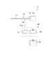
撮像システム1は、内視鏡装置10と、制御ユニット20と、モニタ30とを有する。以下、本実施形態の撮像システム1の概要を説明する。
The
内視鏡装置10は、鏡筒11と、撮像ユニット12とを有する。鏡筒11は、患者の体内に挿入され、疾患部(被写体)へ照明光を照射する。撮像ユニット12は、鏡筒11内を伝送される疾患部の反射光(被写体光束)を受光し、電気信号に変換して画像信号を生成し、生成された画像信号を制御ユニット20へ出力する。
The
制御ユニット20は、光源21と、信号処理部22とを有する。光源21は、光ファイバ等の光伝送部材21aを介して鏡筒11の光源接続部11aに接続され、鏡筒11へ照明光を導入する。信号処理部22は、光源21を制御するとともに、撮像ユニット12から出力される画像信号を処理する。信号処理部22は、画像信号に基づいて疾患部の立体画像(3次元画像)を生成し、モニタ30へ出力する。モニタ30は、X軸方向に水平方向、X軸方向に直交するY軸方向に垂直方向を有する表示部(画面)を有し、上記表示部に疾患部の立体画像を表示させる。
The
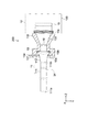
[内視鏡装置]
次に、内視鏡装置10の詳細について説明する。
[Endoscope device]
Next, details of the
図2は、内視鏡装置10の全体構成を示す概略断面図である。内視鏡装置10は、鏡筒11と、撮像ユニット12と、アダプタ13(接続部材)とを有する。
FIG. 2 is a schematic cross-sectional view showing the overall configuration of the
鏡筒11は、図2においてZ軸方向に平行な軸心を有する円筒状の硬性鏡111と、接眼部(アイピース)112とを有する。
The
硬性鏡111は、患者の体内に挿入される先端部111aと、接眼部112と接続される基部111bとを有する。先端部111aは照明光を出射し、被写体からの照明光の反射光が入射するように構成されている。硬性鏡111の内部には、光源接続部11aに導入された照明光を先端部111aへ伝送する照明伝送路と、先端部111aへ入射した被写体光束を基部111bへ伝送する撮像光学系111c(図3(A))が設けられている。
The
接眼部112は、直視により疾患部を観察する際に使用される。接眼部112は、内部に接眼レンズを有してもよい。本実施形態においては、接眼部112を介して疾患部を直視するユーザ(医師)の瞳の位置に被写体光束の絞り位置が対応するように、撮像光学系111cが構成されている。
The
撮像ユニット12は、被写体光束を受光する受光面を有する単板の撮像素子15を有する。撮像素子15は、X軸方向(水平方向)及びY軸方向(垂直方向)に沿って配列された複数の画素を有し、例えばCCD(Charge Coupled Device)、CMOS(Complementary Metal-Oxide Semiconductor)等の固体撮像素子で構成される。撮像素子15の受光面には後述するようにワイヤグリッド偏光子の配列体が構成されている。
The
撮像ユニット12は、撮像素子15を収容する筐体120等をさらに有する。筐体120には、アダプタ13と接続される開口部121を有し、撮像素子15は、121の内部に配置される。
The
アダプタ13は、鏡筒11の接眼部112と接続される第1の接続端部131と、撮像ユニット12の開口部121と接続される第2の接続端部132と、中空部133とを有する。アダプタ13は、鏡筒11の接眼部112を撮像ユニット12へ接続するマウンタとして機能する。アダプタ13には、例えば、Cマウントアダプタが用いられる。
The
アダプタ13は、接眼部112に対して着脱自在に構成されている。これにより長さや径の異なる複数種の鏡筒に対して共通の撮像ユニットを用いることができる。本実施形態において、アダプタ13は、第1の接続端部131に取り付けられ外部からの操作により接眼部112と係合可能な保持具134を有する。第2の接続端部132はネジ部13cを有し、ネジ部13cを介して撮像ユニット12の開口部121に接続されている。
The
図2に示すようにアダプタ13の第1の接続端部131は、接眼部112の端部を収容可能な凹部13aを有し、凹部13aの底部には接眼部112を位置決めする基準面13bが形成される。接眼部112は、その端部が基準面13bに当接することで、アダプタ13との相対位置が規定される。基準面13bは、Z軸と直交して形成される。保持具134は、凹部13aに対する接眼部112の位置決め状態を保持するためのものであり、外部からの操作により第1の接続端部131(凹部13a)に対して図中Y軸方向に挿脱可能な板状部材で構成され、凹部13aへの挿着時に接眼部112の外周部と係合する係合部vを有する。
As shown in FIG. 2, the
中空部133は、アダプタ13をZ軸方向に貫通するように形成され、接眼部112から出射する被写体光束を撮像素子15へ導く通路を構成する。中空部133には、偏光フィルタ14と、結像レンズ16がそれぞれ配置されている。
The
偏光フィルタ14は、接眼部112から投射される被写体光束を2つの偏光成分に分離する2つのフィルタ部を有する。すなわち偏光フィルタ14は、被写体光束のうちX軸方向に振動する第1の偏光成分を透過させY軸方向に振動する第2の偏光成分を遮光する第1のフィルタ部141と、被写体光束のうち上記第1の偏光成分を遮光し上記第2の偏光成分を透過させる第2のフィルタ部142とを有する(図3(B))。
The
本実施形態において偏光フィルタ14は、アダプタ13に内蔵されており、第1の接続端部131の基準面13bに整列するように接眼部112の端部に配置されている。これにより、接眼部112に対するアダプタ13の装着時に、偏光フィルタ14を接眼部112の近傍に自動的に配置することができる。
In the present embodiment, the
結像レンズ16は、偏光フィルタ14と撮像素子15との間に配置される。結像レンズ16は、偏光フィルタ14を通過した被写体光束を撮像素子15の受光面に結像する。
The
図3(A)は、内視鏡装置10の光学系の一例を示す概略図である。
FIG. 3A is a schematic diagram illustrating an example of an optical system of the
撮像光学系111cは、焦点を合わせるためのフォーカスレンズや、被写体を拡大するためのズームレンズ等を含み、一般に、色収差等を補正するために複数枚のレンズの組み合わせによって構成される。偏光フィルタ14は、被写体光束Lの光路上に配置される。本実施形態では偏光フィルタ14は、被写体光束Lの絞り位置に配置される。絞り位置では被写体の1点からの光へ平行光となる。したがって偏光フィルタ14が被写体光束の絞り位置に配置されることにより、偏光フィルタへ平行光の被写体光束を入射させることができ、これにより被写体光束を適正に偏光分離することが可能となる。
The imaging
図3(B)は、Z軸方向から見た偏光フィルタ14の正面図である。偏光フィルタ14は、X軸方向に沿って配列された第1のフィルタ部141及び第2のフィルタ部142を有する。すなわち第1のフィルタ部141及び第2のフィルタ部142は、モニタ20の表示部の左右方向に分割して配列される。第1のフィルタ部141は、被写体光束をX軸方向に偏光し、第2のフィルタ部142は、被写体光束をY軸方向に偏光する。したがって第1のフィルタ部141を通過した第1の偏光光L1の偏光状態と、第2のフィルタ部142を通過した第2の偏光光L2の偏光状態とは、相互に異なる。
FIG. 3B is a front view of the
図3(C)は、撮像素子15の受光面150を示す概略図である。受光面150は、Y軸方向(垂直方向あるいは上下方向)に沿って交互に配置され、X軸方向(水平方向あるいは左右方向)に延びる複数の第1の偏光領域151と第2の偏光領域152とを有する。第1の偏光領域151は、X軸方向に振動する第1の偏光光L1を透過させ、Y軸方向に振動する被写体光束の第2の偏光光L2を遮光する。第2の偏光領域152は、X軸方向に振動する第1の偏光光L1を遮光し、Y軸方向に振動する被写体光束の第2の偏光光L2を透過させる。したがって第1の偏光光L1は、第1の偏光領域151を通過して撮像素子15に到達し、第2の偏光光L2は、第2の偏光光L2は第2の偏光領域152を通過して撮像素子15に到達する。
FIG. 3C is a schematic diagram showing the
撮像素子15は、第1のフィルタ部141の重心点BC1と第2のフィルタ部142の重心点BC2との間の距離を両眼視差の基線長さとした立体画像を得るための画像を撮像する。撮像ユニット12は、撮像素子15の他に、例えば、画像処理部122及び画像記憶部123を有する。画像処理部122は、撮像素子15によって変換された電気信号に基づき、右眼用画像データ及び左眼用画像データを生成し、画像記憶部123に記録する。なお、画像処理部122及び画像記憶部123は、制御ユニット20の信号処理部22に構成されてもよい。
The
偏光フィルタ14の外形形状は円形であり、第1のフィルタ部141及び第2のフィルタ部142は、それぞれ、偏光フィルタ14の半分を占める半円状の外形形状を有する。第1のフィルタ部141と第2のフィルタ部142との境界線は、Y軸方向に延びている。2つのフィルタ部の組み合わせからなる偏光フィルタ14は、入射した光を2つの異なる偏光状態に分離する。
The outer shape of the
偏光フィルタ14は、上述したとおり、左右対称の偏光子から構成されており、内視鏡装置10の正立状態に対する左右2つの位置において、互いに直交する直線方向の偏光、又は、互いに逆方向となる回転方向の偏光を生成する。第1のフィルタ部141は、被写体を右眼で見るであろう像(右眼が受けるであろう光)に対して偏光を施すフィルタである。一方、第2のフィルタ部142は、被写体を左眼で見るであろう像(左眼が受けるであろう光)に対して偏光を施すフィルタである。
As described above, the
図3(B)において、第1の偏光光L1の電場の向き(白抜きの矢印で示す)と第2の偏光光L2の電場の向き(白抜きの矢印で示す)とは直交している。ここで、第1の偏光光L1の電場の向きはX軸方向と平行である。具体的には、例えば、第1の偏光光L1は主としてP波(TM波)を偏光成分として有し、第2の偏光光L2は主としてS波(TE波)を偏光成分として有する。 In FIG. 3B, the direction of the electric field of the first polarized light L1 (indicated by a white arrow) is orthogonal to the direction of the electric field of the second polarized light L2 (indicated by a white arrow). . Here, the direction of the electric field of the first polarized light L1 is parallel to the X-axis direction. Specifically, for example, the first polarized light L1 mainly has a P wave (TM wave) as a polarization component, and the second polarized light L2 mainly has an S wave (TE wave) as a polarization component.
更に図3(C)に示すように、第1の偏光光L1の電場の向きと第1の偏光領域151の電場の向き(白抜きの矢印で示す)とは平行であり、第2の偏光光L2の電場の向きと第2の偏光領域152の電場の向き(白抜きの矢印で示す)とは平行である。また、各偏光子の消光比は、3以上、より好ましくは、10以上である。 Further, as shown in FIG. 3C, the direction of the electric field of the first polarized light L1 and the direction of the electric field of the first polarizing region 151 (shown by a white arrow) are parallel, and the second polarized light The direction of the electric field of the light L2 and the direction of the electric field of the second polarization region 152 (indicated by a white arrow) are parallel. Moreover, the extinction ratio of each polarizer is 3 or more, more preferably 10 or more.
本実施形態においては、偏光フィルタ14の外形形状は、半径r=10mmの円形とした。そして、第1のフィルタ部141及び第2のフィルタ部142は、偏光フィルタ14の半分を占める半円形状とした。したがって、第1のフィルタ部141の重心点BC1と第2のフィルタ部142の重心点BC2との間の距離は、[(8r)/(3π)]=8.5mmである。
In the present embodiment, the outer shape of the
撮像素子15の受光面150に配置される第1の偏光領域151及び第2の偏光領域152は、それぞれ、ワイヤグリッド偏光子で構成される。図4(A)は撮像素子15の構成を模式的に示す断面図、図4(B)は第1及び第2の偏光領域151,152の配列状態を模式的に示すZ軸方向から見た正面図である。
The
撮像素子15は、例えば、シリコン半導体基板60に設けられた光電変換素子61、並びに、その上に、第1の平坦化膜62、カラーフィルタ63、オンチップレンズ64、第2の平坦化膜65、無機絶縁下地層66、及び、ワイヤグリッド偏光子67が積層された構造を有する。そして、ワイヤグリッド偏光子67が、第1の偏光領域151及び第2の偏光領域152のそれぞれを構成する。図4(B)においては、画素の境界領域は実線で示されている。
The
ワイヤグリッド偏光子67を構成する複数のワイヤ68の延びる方向は、X軸方向あるいはY軸方向と平行である。具体的には、第1の偏光領域151を構成するワイヤグリッド偏光子67Aにあっては、ワイヤ68Aの延びる方向はY軸方向と平行であり、第2の偏光領域152を構成するワイヤグリッド偏光子67Bにあっては、ワイヤ68Bの延びる方向はX軸方向と平行である。ワイヤ68の延びる方向と直交する方向がワイヤグリッド偏光子67における光透過軸となる。
The extending direction of the plurality of
本実施形態においては、第1の偏光領域151を通過して撮像素子15に到達した第1の偏光光L1によって、右眼用画像データを得るための電気信号が撮像素子15において生成される。また、第2の偏光領域152を通過して撮像素子15に到達した第2の偏光光L2によって、左眼用画像データを得るための電気信号が撮像素子15において生成される。撮像素子15は、これらの電気信号を、同時に、又は、時系列に交互に、出力する。出力された電気信号(撮像素子15から出力された右眼用画像データ及び左眼用画像データを得るための電気信号)に対して、画像処理部122によって画像処理が施され、右眼用画像データ及び左眼用画像データとして画像記憶部123に記録される。
In the present embodiment, an electrical signal for obtaining right-eye image data is generated in the
図5(A)及び(B)は、被写体から撮像素子15へ到達する光の概念図であり、図5(C)及び(D)は、図5(A)及び(B)に示した光によって撮像素子に結像した画像を模式的に示す図である。
5A and 5B are conceptual diagrams of light reaching the
図5(A)及び(B)に模式的に示すように、四角い形状の物体Aに撮像光学系111cのピントが合っているとする。また、丸い形状の物体Bが、物体Aよりも撮像光学系111cに近く位置しているとする。四角い物体Aの像が、ピントが合った状態で撮像素子15上に結像する。また、丸い物体Bの像は、ピントが合っていない状態で撮像素子15上に結像する。そして、図5(A)に示す例にあっては、撮像素子15上では、物体Bは、物体Aの右手側に距離(+ΔX)だけ離れた位置に像を結ぶ。一方、図5(B)に示す例にあっては、撮像素子15上では、物体Bは、物体Aの左手側に距離(−ΔX)だけ離れた位置に像を結ぶ。従って、距離(2×ΔX)が物体Bの奥行きに関する情報となる。すなわち物体Aよりも内視鏡装置に近い側に位置する物体Bのボケ量及びボケ方向は、内視鏡装置に遠い側に位置する物体のボケ量及びボケ方向と異なるし、物体Aと物体Bとの距離によって物体Bのボケ量は異なる。
As schematically shown in FIGS. 5A and 5B, it is assumed that the imaging
そして、偏光フィルタ14における第1のフィルタ部141及び第2のフィルタ部142の形状の重心位置の間の距離を両眼視差の基線長さとした立体画像を得ることができる。すなわちこのようにして得られた右眼用画像(図5(C)の模式図参照)及び左眼画像(図5(D)の模式図参照)から、周知の方法に基づき立体画像を得ることができる。なお、右眼用画像データと左眼用画像データとを混合すれば、立体画像ではない、通常の2次元(平面)画像を得ることができる。
Then, a stereoscopic image can be obtained in which the distance between the gravity center positions of the shapes of the
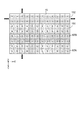
図6は、撮像素子15の受光面を説明する概念図である。
FIG. 6 is a conceptual diagram illustrating the light receiving surface of the
撮像素子15はベイヤ配列を有し、1画素は4つのサブ画素(赤色を受光する1つの赤色画素R、青色を受光する1つの青色画素B、及び、緑色を受光する2つの緑色画素G)から構成されている。そして、X軸方向に沿って配列された1行の画素群に対して第1の偏光領域151が配置されており、同様に、この画素群にY軸方向に隣接し、X軸方向に沿って配列された1行の画素群に対して第2の偏光領域152が配置されている。第1の偏光領域151と第2の偏光領域152とは、Y軸方向に沿って交互に配置されている。
The
第1の偏光領域151及び第2の偏光領域152は全体としてX軸方向に延びているが、第1の偏光領域151及び第2の偏光領域152のX軸方向及びY軸方向に沿った単位長さは、撮像素子15のX軸方向及びY軸方向に沿った長さと等しい。そして、このような構成とすることで、主としてP波成分を有する光に基づくX軸方向に延びる帯状の画像(右眼用画像)、及び、主としてS波製粉を有する光に基づくX軸方向に延びる帯状の画像(左眼用画像)が、Y軸方向に沿って交互に生成される。図6において、第1の偏光領域151の内部に縦線を付し、第2の偏光領域152の内部に横線を付しているが、これらは、ワイヤグリッド偏光子67A,67Bのワイヤを模式的に表している。
Although the
右眼用画像データ及び左眼用画像データのための電気信号は、上述したとおり、Y軸方向に沿って、1行おきに生成される。そこで、画像処理部122は、右眼用画像データ及び左眼用画像データの作成のために、電気信号に対してモザイク処理を施すと共に、例えば、超解像処理を行うことにより、最終的に右眼用画像データ及び左眼用画像データを生成、作成する。また、例えば、左眼用画像データと右眼用画像データからステレオマッチングによりデイスパリティ・マップ(Disparity Map)を作成するといった視差検出技術、及び、デイスパリティ・マップを基に視差を制御する視差制御技術により、視差の強調、適切化を図ることもできる。
As described above, the electrical signals for the right-eye image data and the left-eye image data are generated every other row along the Y-axis direction. Therefore, the
図7に、撮像素子から得られた電気信号に対するモザイク処理を行い、信号値を得る画像処理(モザイク処理)を説明するためのベイヤ配列を有する受光面の概念図を示す。図7には、左眼用画像における緑色画素に関する信号値を生成する例について示している。 FIG. 7 shows a conceptual diagram of a light receiving surface having a Bayer array for explaining image processing (mosaic processing) for obtaining a signal value by performing mosaic processing on an electrical signal obtained from an image sensor. FIG. 7 shows an example in which a signal value related to a green pixel in the left eye image is generated.
通常のデモザイク処理では、近傍の同一色の画素の電気信号の平均値が用いられるのが一般的である。しかしながら、本実施形態のように右眼用画像データを得るための画素群(画素行)と左眼用画像データを得るための画素群(画素行)とが交互に繰り返されている場合、そのまま、近傍の値を用いると本来の画像データが得られなくなる虞がある。そこで、参照される画素の電気信号が右眼用画像データ及び左眼用画像データの何れに相当するものであるかを考慮した上で、デモザイク処理を行う。 In normal demosaic processing, an average value of electrical signals of pixels of the same color in the vicinity is generally used. However, when a pixel group (pixel row) for obtaining right-eye image data and a pixel group (pixel row) for obtaining left-eye image data are alternately repeated as in the present embodiment, the state is unchanged. If the values in the vicinity are used, the original image data may not be obtained. Therefore, the demosaic process is performed in consideration of which of the right-eye image data and the left-eye image data corresponds to the electric signal of the pixel to be referred to.
ベイヤ配列において、位置(4,2)には赤色画素Rが配置されているものとする。このとき、位置(4,2)に相当する緑色画素信号値g’を生成するためには、次式によって表される演算を行う。 In the Bayer array, it is assumed that a red pixel R is arranged at the position (4, 2). At this time, in order to generate the green pixel signal value g ′ corresponding to the position (4, 2), an operation represented by the following equation is performed.
g’4,2=(g4,1+g4,3+g5,2+g1,2×W3)/(3.0+W3) g'4,2 = (g4,1 + g4,3 + g5,2 + g1,2 × W3) / (3.0 + W3)
ここで、左辺のg’i,jは、位置(i,j)における緑色画素信号値である。また、右辺のgi,jは、位置(i,j)における緑色画素の電気信号の値である。更には、「3.0」は、注目画素G4,2に対する隣接画素G4,1,G4,3,G5,2への距離(W1)をそれぞれ例えば「1.0」としたとき、その逆数を重みとして、それら重みの総和に対応するものである。W3は、同様に、3画素分だけ離れた画素G1,2の電気信号の値に対する重みであり、この場合、「1/3」である。上式を一般化すると、次式のようになる。 Here, g′i, j on the left side is the green pixel signal value at the position (i, j). Also, gi, j on the right side is the value of the electrical signal of the green pixel at position (i, j). Furthermore, “3.0” is the reciprocal when the distance (W1) to the adjacent pixels G4,1, G4,3, G5,2 with respect to the target pixel G4,2 is, for example, “1.0”. The weight corresponds to the sum of the weights. Similarly, W3 is a weight for the value of the electrical signal of the pixels G1, 2 separated by 3 pixels, and in this case, “1/3”. When the above equation is generalized, the following equation is obtained.
iが偶数の場合(赤色画素Rの位置に相当する緑色画素Gの信号値);
g’i,j=(gi,j-1×W1+gi,j+1×W1+gi+1,j×W1+gi-3,j×W3)/(W1×3.0+W3)
iが帰趨の場合(青色画素Bの位置に相当する緑色画素Gの信号値);
g’i,j=(gi,j-1×W1+gi,j+1×W1+gi-1,j×W1+gi+3,j×W3)/(W1×3.0+W3)
ここで、W1=1.0、W3=1/3である。
When i is an even number (the signal value of the green pixel G corresponding to the position of the red pixel R);
g'i, j = (gi, j-1 * W1 + gi, j + 1 * W1 + gi + 1, j * W1 + gi-3, j * W3) / (W1 * 3.0 + W3)
if i is a return (signal value of the green pixel G corresponding to the position of the blue pixel B);
g'i, j = (gi, j-1 * W1 + gi, j + 1 * W1 + gi-1, j * W1 + gi + 3, j * W3) / (W1 * 3.0 + W3)
Here, W1 = 1.0 and W3 = 1/3.
赤色画素R及び青色画素Bについても、同様の考え方によりモザイク処理を行うことができる。 With respect to the red pixel R and the blue pixel B, mosaic processing can be performed based on the same concept.
デモザイク処理により各画素位置における画素信号値を得ることができるが、この段階では、上述した1行おきの状態となっている。そのため、画素信号値が存在しない領域に対して、画素信号値を補間(補完)により生成する必要がある。補間の手法としては、近傍の値の加算平均値を利用する方法等、周知の方法を挙げることができる。この補間処理は、デモザイク処理と並行して行ってもよい。X軸方向においては画質は完全に保持されているので、画像全体の解像度低下等の画質劣化は比較的少ない。 Although the pixel signal value at each pixel position can be obtained by demosaic processing, at this stage, the state is every other row described above. Therefore, it is necessary to generate a pixel signal value by interpolation (complementation) for an area where no pixel signal value exists. As an interpolation method, a known method such as a method of using an average value of neighboring values can be used. This interpolation process may be performed in parallel with the demosaic process. Since the image quality is completely maintained in the X-axis direction, image quality degradation such as a reduction in resolution of the entire image is relatively small.
本実施形態によれば、偏光フィルタ14で左右に分離された2つの異なる画像を同時に生成させることができ、単眼で疾患部の立体画像を取得することができる。また、簡素な構成、構造を有し、構成部品の少ない、小型の内視鏡装置10を提供することができる。また、レンズ及び偏光フィルタの組み合わせを複数組必要としないので、ズーム、絞り部、フォーカス、輻輳角等にズレや差異が生じることもない。しかも、両眼視差の基線長さが比較的短いので、自然な立体感を得ることができる。更には、偏光フィルタ14をアダプタ13に対して脱着させ得る構造とれば、容易に、2次元画像及び3次元画像を得ることができる。
According to the present embodiment, two different images separated on the left and right by the
<第2の実施形態>
図8は、本技術の第2の実施形態に係る内視鏡装置の全体構成を示す概略断面図である。以下、第1の実施形態と異なる構成について主に説明し、上述の実施形態と同様の構成については同様の符号を付しその説明を省略または簡略化する。
<Second Embodiment>
FIG. 8 is a schematic cross-sectional view illustrating an overall configuration of an endoscope apparatus according to the second embodiment of the present technology. Hereinafter, configurations different from those of the first embodiment will be mainly described, and configurations similar to those of the above-described embodiment will be denoted by the same reference numerals, and description thereof will be omitted or simplified.
本実施形態の内視鏡装置200においては、偏光フィルタ24が鏡筒11の硬性鏡111内に配置されている点で、上述の第1の実施形態と異なる。偏光フィルタ24は、第1の実施形態で説明した偏光フィルタ14と同様の構成を有しており、硬性鏡111内の撮像光学系における被写体光束の絞り部(図示略)に配置される。絞り部は、集光された光の量を調整するために光を絞り込む機能を有するものであり、例えば、複数枚の板状の羽根を組み合わせて構成されている。
The
偏光フィルタ24は、上記絞り部の近傍に配置されている。偏光フィルタ24は、上記絞り部の作動に支障を来たさない限り、出来るだけ絞り部に近い位置に配置される。これにより平行光の被写体光束を偏光フィルタに入射させることができるため、被写体光束を適正に偏光分離することが可能とる。
The
以上の構成を有する本実施形態に係る内視鏡装置200においても、上述の第1の実施形態と同様の作用効果を得ることができる。
Also in the
<第3の実施形態>
図9は、本技術の第2の実施形態に係る内視鏡装置の全体構成を示す概略断面図である。以下、第1の実施形態と異なる構成について主に説明し、上述の実施形態と同様の構成については同様の符号を付しその説明を省略または簡略化する。
<Third Embodiment>
FIG. 9 is a schematic cross-sectional view showing an overall configuration of an endoscope apparatus according to the second embodiment of the present technology. Hereinafter, configurations different from those of the first embodiment will be mainly described, and configurations similar to those of the above-described embodiment will be denoted by the same reference numerals, and description thereof will be omitted or simplified.
本実施形態の内視鏡装置300においては、偏光フィルタ34が撮像ユニット12の筐体120内に配置されている点で、上述の第1の実施形態と異なる。偏光フィルタ34は、第1の実施形態で説明した偏光フィルタ14と同様の構成を有しており、筐体120内の撮像光学系における被写体光束の絞り部(図示略)に配置される。絞り部には、上述した絞り機能を有する光学部品が配置されてもよい。
The
本実施形態では、偏光フィルタ34と撮像素子15との間に結像レンズ16が配置される。アダプタ13の内部には、接眼部112から出射した被写体光束を偏光フィルタ34に投影する光学レンズ17が配置されている。
In the present embodiment, the
以上の構成を有する本実施形態に係る内視鏡装置200においても、上述の第1の実施形態と同様の作用効果を得ることができる。
Also in the
以上、本技術の実施形態について説明したが、本技術は上述の実施形態にのみ限定されるものではなく、本技術の要旨を逸脱しない範囲内において種々変更を加え得ることは勿論である。 As mentioned above, although embodiment of this technique was described, this technique is not limited only to the above-mentioned embodiment, Of course, in the range which does not deviate from the summary of this technique, various changes can be added.
例えば以上の実施形態では、本技術に係る撮像装置を、医療現場において使用される内視鏡装置へ適用した例を説明したが、本技術はこれに限られず、例えば顕微鏡や工業用内視鏡等にも適用可能である。 For example, in the above embodiment, the example in which the imaging device according to the present technology is applied to an endoscope device used in a medical field has been described. However, the present technology is not limited to this, for example, a microscope or an industrial endoscope. The present invention can also be applied.
また以上の実施形態では、第1の偏光光L1の電場の向きがX軸方向と平行に、第2の偏光光L2の電場の向きがY軸方向と平行になるように偏光フィルタ14が構成された。これに代えて、偏光フィルタは、第1の偏光光及び第2の偏光光の各々の電場の向きがそれぞれX軸方向及びY軸方向と45度の角度をなすように構成されてもよい。
In the above embodiment, the
図10(A)は、上述のように構成された偏光フィルタ44の概略図である。第1のフィルタ部441及び第2のフィルタ部442はそれぞれ、白抜き矢印で示す方向に電場方向を有する第1の偏光光及び第2の偏光光を形成する。これら第1の偏光光及び第2の偏光光は、それぞれ直交する偏光成分で構成される。この場合、撮像素子45の受光面は、図10(B)に示すような偏光領域が形成される。第1の偏光領域451の光透過軸は、第1の偏光光の電場方向と平行とされ、第2の偏光領域452の光透過軸は、第2の偏光光の電場方向と平行とされる。これら第1の偏光領域451及び第2の偏光領域452は、それぞれ上述したような構成のワイヤグリッド偏光子で構成することができる。以上のような構成においても、上述の実施形態と同様の作用効果を得ることができる。
FIG. 10A is a schematic diagram of the
なお、本技術は以下のような構成も採ることができる。
(1)接眼部を有し、被写体光束を伝送する鏡筒と、
前記被写体光束のうち第1の方向に振動する第1の偏光成分を透過させ前記第1の方向と直交する第2の方向に振動する第2の偏光成分を遮光する第1のフィルタ部と、前記被写体光束のうち前記第1の偏光成分を遮光し前記第2の偏光成分を透過させる第2のフィルタ部とを有し、前記被写体光束の光路上に配置された偏光フィルタと、
前記接眼部に接続され、前記第1の偏光成分と前記第2の偏光成分とを受光する撮像素子を有する撮像ユニットと
を具備する撮像装置。
(2)上記(1)に記載の撮像装置であって、
前記偏光フィルタは、前記光路の絞り位置に配置される
撮像装置。
(3)上記(1)又は上記(2)に記載の撮像装置であって、
前記偏光フィルタは、前記接眼部に配置される
撮像装置。
(4)上記(1)から(3)のいずれか1項に記載の撮像装置であって、
前記接眼部と前記撮像ユニットとの間を接続する接続部材をさらに具備し、
前記偏光フィルタは、前記接続部材に内蔵される
撮像装置。
(5)上記(4)に記載の撮像装置であって、
前記接続部材は、前記接眼部に対して着脱自在に構成される
撮像装置。
(6)上記(4)又は(5)に記載の撮像装置であって、
前記偏光フィルタは、前記接続部材に対して着脱自在に構成される
撮像装置。
(7)上記(1)から(6)のいずれか1項に記載の撮像装置であって、
前記撮像素子は、前記第1の偏光成分を透過し前記第2の偏光成分を遮光する複数の第1の偏光子と、前記第1の偏光成分を遮光し前記第2の偏光成分を透過する複数の第2の偏光子とがマトリクス状に配列された受光面を有する
撮像装置。
(8)上記(5)に記載の撮像装置であって、
前記接続部材は、前記接続端部に取り付けられ外部からの操作により前記接眼部と係合可能な保持具を有する
撮像装置。
In addition, this technique can also take the following structures.
(1) a lens barrel having an eyepiece and transmitting a subject luminous flux;
A first filter unit that transmits a first polarization component that vibrates in a first direction of the subject luminous flux and shields a second polarization component that vibrates in a second direction orthogonal to the first direction; A polarizing filter disposed on an optical path of the subject light beam, and having a second filter unit that blocks the first polarization component of the subject light beam and transmits the second polarization component;
An imaging apparatus comprising: an imaging unit that is connected to the eyepiece unit and has an imaging element that receives the first polarization component and the second polarization component.
(2) The imaging apparatus according to (1) above,
The polarization filter is disposed at a stop position of the optical path.
(3) The imaging apparatus according to (1) or (2),
The polarizing filter is disposed in the eyepiece unit.
(4) The imaging apparatus according to any one of (1) to (3) above,
Further comprising a connecting member for connecting between the eyepiece and the imaging unit;
The polarizing filter is an imaging device built in the connection member.
(5) The imaging apparatus according to (4) above,
The imaging device is configured such that the connection member is detachable from the eyepiece.
(6) The imaging apparatus according to (4) or (5) above,
The polarizing filter is configured to be detachable from the connection member.
(7) The imaging apparatus according to any one of (1) to (6) above,
The imaging device transmits a plurality of first polarizers that transmit the first polarization component and shields the second polarization component, and shields the first polarization component and transmits the second polarization component. An imaging apparatus having a light receiving surface in which a plurality of second polarizers are arranged in a matrix.
(8) The imaging device according to (5) above,
The said connection member has a holder attached to the said connection end part, and can be engaged with the said eyepiece part by the operation from the outside.
1…撮像システム
10,200,300…内視鏡装置
11…鏡筒
12…撮像ユニット
13…アダプタ
14,24,34,44…偏光フィルタ
15,45…撮像素子
20…制御ユニット
30…モニタ
67,67A,67B…ワイヤグリッド偏光子
111…硬性鏡
112…接眼部
134…保持具
141,441…第1のフィルタ部
142,442…第2のフィルタ部
151,451…第1の偏光領域
152,452…第2の偏光領域
DESCRIPTION OF
Claims (9)
接眼部を有し、被写体光束を伝送する鏡筒と、
前記被写体光束のうち第1の方向に振動する第1の偏光成分を透過させ前記第1の方向と直交する第2の方向に振動する第2の偏光成分を遮光する第1のフィルタ部と、前記被写体光束のうち前記第1の偏光成分を遮光し前記第2の偏光成分を透過させる第2のフィルタ部とを有し、前記被写体光束の光路上に配置されることが可能に構成された偏光フィルタと、
前記接眼部に接続され、前記第1の偏光成分と前記第2の偏光成分とを受光する撮像素子を有する撮像ユニットと、
前記接眼部と前記撮像ユニットとの間を接続し、前記偏光フィルタを内蔵する接続部材と
を具備する撮像装置。 An imaging apparatus configured to be able to selectively obtain a two-dimensional image and a three-dimensional image of a subject,
A lens barrel having an eyepiece and transmitting a subject luminous flux;
A first filter unit that transmits a first polarization component that vibrates in a first direction of the subject luminous flux and shields a second polarization component that vibrates in a second direction orthogonal to the first direction; A second filter unit that blocks the first polarization component of the subject light beam and transmits the second polarization component, and is configured to be disposed on an optical path of the subject light beam. A polarizing filter;
An imaging unit having an imaging device connected to the eyepiece and receiving the first polarization component and the second polarization component ;
An imaging apparatus comprising: a connecting member that connects between the eyepiece unit and the imaging unit and includes the polarization filter .
前記被写体光束を前記偏光フィルタに入射させる場合に前記3次元画像を得、
前記被写体光束を前記偏光フィルタに入射させない場合に前記2次元画像を得る
撮像装置。 The imaging apparatus according to claim 1,
Obtaining the three-dimensional image when the subject luminous flux is incident on the polarizing filter;
An imaging apparatus that obtains the two-dimensional image when the subject luminous flux is not incident on the polarization filter.
前記偏光フィルタが前記被写体光束の光路上に配置された場合に前記3次元画像を得、
前記偏光フィルタが前記被写体光束の光路上に配置されない場合に前記2次元画像を得る
撮像装置。 The imaging apparatus according to claim 1,
Obtaining the three-dimensional image when the polarizing filter is disposed on the optical path of the subject luminous flux;
An imaging apparatus that obtains the two-dimensional image when the polarizing filter is not disposed on an optical path of the subject light beam.
前記偏光フィルタは、前記光路の絞り位置に配置される
撮像装置。 The imaging apparatus according to any one of claims 1 to 3,
The polarization filter is disposed at a stop position of the optical path.
前記偏光フィルタは、前記接眼部に配置される
撮像装置。 The imaging apparatus according to claim 4,
The polarizing filter is disposed in the eyepiece unit.
前記接続部材は、前記接眼部に対して着脱自在に構成される
撮像装置。 The imaging apparatus according to claim 1 ,
The imaging device is configured such that the connection member is detachable from the eyepiece.
前記偏光フィルタは、前記接続部材に対して着脱自在に構成される
撮像装置。 The imaging apparatus according to any one of claims 1 to 6 ,
The polarizing filter is configured to be detachable from the connection member.
前記撮像素子は、前記第1の偏光成分を透過し前記第2の偏光成分を遮光する複数の第1の偏光子と、前記第1の偏光成分を遮光し前記第2の偏光成分を透過する複数の第2の偏光子とがマトリクス状に配列された受光面を有する
撮像装置。 The imaging apparatus according to any one of claims 1 to 7 ,
The imaging device transmits a plurality of first polarizers that transmit the first polarization component and shields the second polarization component, and shields the first polarization component and transmits the second polarization component. An imaging apparatus having a light receiving surface in which a plurality of second polarizers are arranged in a matrix.
前記接続部材は、外部からの操作により前記接眼部と係合可能な保持具を有する
撮像装置。 The imaging apparatus according to claim 6 ,
The connection member includes a holder that can be engaged with the eyepiece unit by an operation from the outside.
Priority Applications (4)
| Application Number | Priority Date | Filing Date | Title |
|---|---|---|---|
| JP2011248694A JP6010895B2 (en) | 2011-11-14 | 2011-11-14 | Imaging device |
| US13/670,611 US20130182169A1 (en) | 2011-11-14 | 2012-11-07 | Imaging apparatus |
| CN201210441765.XA CN103105681B (en) | 2011-11-14 | 2012-11-07 | Imaging device |
| US15/231,288 US10185138B2 (en) | 2011-11-14 | 2016-08-08 | Imaging apparatus |
Applications Claiming Priority (1)
| Application Number | Priority Date | Filing Date | Title |
|---|---|---|---|
| JP2011248694A JP6010895B2 (en) | 2011-11-14 | 2011-11-14 | Imaging device |
Publications (3)
| Publication Number | Publication Date |
|---|---|
| JP2013106189A JP2013106189A (en) | 2013-05-30 |
| JP2013106189A5 JP2013106189A5 (en) | 2014-12-25 |
| JP6010895B2 true JP6010895B2 (en) | 2016-10-19 |
Family
ID=48313659
Family Applications (1)
| Application Number | Title | Priority Date | Filing Date |
|---|---|---|---|
| JP2011248694A Expired - Fee Related JP6010895B2 (en) | 2011-11-14 | 2011-11-14 | Imaging device |
Country Status (3)
| Country | Link |
|---|---|
| US (2) | US20130182169A1 (en) |
| JP (1) | JP6010895B2 (en) |
| CN (1) | CN103105681B (en) |
Families Citing this family (12)
| Publication number | Priority date | Publication date | Assignee | Title |
|---|---|---|---|---|
| WO2015015717A1 (en) | 2013-07-30 | 2015-02-05 | パナソニックIpマネジメント株式会社 | Imaging device and imaging system, electronic mirroring system, and distance measurement device using same |
| JP5968944B2 (en) * | 2014-03-31 | 2016-08-10 | 富士フイルム株式会社 | Endoscope system, processor device, light source device, operation method of endoscope system, operation method of processor device, operation method of light source device |
| US20200092448A1 (en) * | 2014-07-25 | 2020-03-19 | SMR Patents S.à.r.l. | Apparatus for light intensity adjustment |
| EP2978209B1 (en) * | 2014-07-25 | 2018-03-07 | SMR Patents S.à.r.l. | Apparatus for light intensity adjustment |
| CN105511093B (en) * | 2015-06-18 | 2018-02-09 | 广州优视网络科技有限公司 | 3D imaging methods and device |
| WO2017072883A1 (en) * | 2015-10-28 | 2017-05-04 | オリンパス株式会社 | Optical adjustment device and optical device equipped with optical adjustment device |
| CN105511071B (en) * | 2016-01-19 | 2018-08-24 | 珠海康弘发展有限公司 | The method of endoscope, ray machine attachment device and the two-dimentional endoscopic system of transformation |
| JP6646133B2 (en) * | 2016-02-23 | 2020-02-14 | オリンパス株式会社 | Image processing device and endoscope |
| KR101921268B1 (en) * | 2016-12-21 | 2018-11-22 | 주식회사 인트로메딕 | Capsule endoscopy apparatus for rendering 3d image, operation method of said capsule endoscopy, receiver rendering 3d image interworking with said capsule endoscopy, and capsule endoscopy system |
| EP3559723A4 (en) * | 2016-12-22 | 2020-07-29 | Z Square Ltd. | Illumination sources for multicore fiber endoscopes |
| US10779715B2 (en) * | 2017-02-23 | 2020-09-22 | Sony Olympus Medical Solutions Inc. | Endoscope apparatus |
| US10890778B2 (en) * | 2019-06-11 | 2021-01-12 | Facebook Technologies, Llc | Optical system having an improved signal-to-noise ratio of eye-tracking |
Family Cites Families (21)
| Publication number | Priority date | Publication date | Assignee | Title |
|---|---|---|---|---|
| US3827793A (en) | 1972-11-03 | 1974-08-06 | Dudley Optical Labor Inc | Stereoscopic microscopy |
| US5385138A (en) | 1992-01-21 | 1995-01-31 | Berry; Yale | Stereo endoscope for inserting into body cavities |
| GR1002336B (en) | 1992-05-06 | 1996-05-21 | Ethicon Inc. | Endoscopic surgical apparatus capable of ligation and division. |
| US5588948A (en) | 1993-02-17 | 1996-12-31 | Olympus Optical Co. Ltd. | Stereoscopic endoscope |
| JPH0720388A (en) | 1993-07-05 | 1995-01-24 | Shinko Koki Seisakusho:Kk | Stereoscopic endoscope device |
| JPH08304718A (en) * | 1994-11-02 | 1996-11-22 | Terumo Corp | Endoscope device, image processor for endoscope and endoscope control method |
| JPH0990241A (en) * | 1995-09-20 | 1997-04-04 | Terumo Corp | Endoscope |
| US5649897A (en) | 1994-11-02 | 1997-07-22 | Terumo Kabushiki Kaisha | Endoscope apparatus for compensating for change in polarization state during image transmission |
| DE69627497T2 (en) * | 1995-05-24 | 2003-12-24 | Olympus Optical Co | STEREOSCOPIC ENDOSCOPE AND TV IMAGE SYSTEM FOR THE ENDOSCOPE |
| JPH1062697A (en) | 1996-08-21 | 1998-03-06 | Olympus Optical Co Ltd | Stereoscopic endoscope device |
| JPH10248807A (en) * | 1997-03-13 | 1998-09-22 | Olympus Optical Co Ltd | Endoscope device |
| US6503195B1 (en) | 1999-05-24 | 2003-01-07 | University Of North Carolina At Chapel Hill | Methods and systems for real-time structured light depth extraction and endoscope using real-time structured light depth extraction |
| US20020054431A1 (en) | 2000-11-03 | 2002-05-09 | Bryan Costales | Single-lens stereoscopic infinity microscope |
| CN2470846Y (en) * | 2001-02-13 | 2002-01-09 | 麦克奥迪实业集团有限公司 | Device for realizing steroview on single objective double-eye viewing optical path |
| JP4500360B2 (en) * | 2007-06-15 | 2010-07-14 | パナソニック株式会社 | Image processing device |
| CN101843471B (en) * | 2009-03-26 | 2012-10-24 | 锐意视觉科技(北京)有限公司 | Single-camera stereoscopic endoscope system |
| JP5359465B2 (en) * | 2009-03-31 | 2013-12-04 | ソニー株式会社 | Solid-state imaging device, signal processing method for solid-state imaging device, and imaging device |
| JP5391914B2 (en) * | 2009-08-06 | 2014-01-15 | ソニー株式会社 | Imaging apparatus and video recording / reproducing system |
| JP2011139209A (en) * | 2009-12-28 | 2011-07-14 | Sony Corp | Image processing apparatus and method |
| JP2011145343A (en) * | 2010-01-12 | 2011-07-28 | Sony Corp | Barrel device and three-dimensional imaging apparatus |
| EP2531884A1 (en) | 2010-02-03 | 2012-12-12 | Battelle Memorial Institute | Three-dimensional imaging system using a single lens system |
-
2011
- 2011-11-14 JP JP2011248694A patent/JP6010895B2/en not_active Expired - Fee Related
-
2012
- 2012-11-07 US US13/670,611 patent/US20130182169A1/en not_active Abandoned
- 2012-11-07 CN CN201210441765.XA patent/CN103105681B/en not_active Expired - Fee Related
-
2016
- 2016-08-08 US US15/231,288 patent/US10185138B2/en not_active Expired - Fee Related
Also Published As
| Publication number | Publication date |
|---|---|
| US20130182169A1 (en) | 2013-07-18 |
| CN103105681B (en) | 2017-11-17 |
| CN103105681A (en) | 2013-05-15 |
| US20170003494A1 (en) | 2017-01-05 |
| US10185138B2 (en) | 2019-01-22 |
| JP2013106189A (en) | 2013-05-30 |
Similar Documents
| Publication | Publication Date | Title |
|---|---|---|
| JP6010895B2 (en) | Imaging device | |
| JP5974658B2 (en) | Imaging device | |
| JP5730339B2 (en) | Stereoscopic endoscope device | |
| JP5695808B1 (en) | Endoscope device | |
| US20110043612A1 (en) | Dual-tube stereoscope | |
| JP5454424B2 (en) | Imaging method | |
| KR101785754B1 (en) | Imaging device and imaging method | |
| WO2017073323A1 (en) | Surgical microscope, image processing device, and image processing method | |
| JP5053468B2 (en) | Stereoscopic image capturing apparatus and endoscope | |
| JP4971532B1 (en) | Stereoscopic image capturing apparatus and endoscope | |
| EP2577977A1 (en) | Two sensor imaging systems | |
| JP2015135511A (en) | Camera adaptor for medical-optical observation instrument and camera-adaptor combination | |
| JP2015126288A (en) | Adjustment jig of stereoscopic observation apparatus and stereoscopic observation system | |
| JPH0735989A (en) | Stereoscopic viewing endoscope | |
| JP2013223666A (en) | Electronic endoscope, image processor, electronic endoscope system, and image generation method for stereoscopic vision | |
| JP6160749B2 (en) | Endoscope adapter | |
| WO2021131921A1 (en) | Rigid mirror device | |
| JP5907668B2 (en) | Imaging device and imaging device | |
| JP2011191517A (en) | Stereomicroscope and control device for microscope | |
| JP3816589B2 (en) | Stereoscopic endoscope | |
| WO2015182306A1 (en) | Imaging device and synthesized-image display device | |
| JP5452800B2 (en) | Stereoscopic imaging device | |
| JPH10276964A (en) | Stereoscopic endoscope | |
| JPH05115068A (en) | Image pickup device for endoscope |
Legal Events
| Date | Code | Title | Description |
|---|---|---|---|
| A521 | Request for written amendment filed |
Free format text: JAPANESE INTERMEDIATE CODE: A523 Effective date: 20141106 |
|
| A621 | Written request for application examination |
Free format text: JAPANESE INTERMEDIATE CODE: A621 Effective date: 20141106 |
|
| A977 | Report on retrieval |
Free format text: JAPANESE INTERMEDIATE CODE: A971007 Effective date: 20150710 |
|
| A131 | Notification of reasons for refusal |
Free format text: JAPANESE INTERMEDIATE CODE: A131 Effective date: 20150811 |
|
| A521 | Request for written amendment filed |
Free format text: JAPANESE INTERMEDIATE CODE: A523 Effective date: 20151008 |
|
| A131 | Notification of reasons for refusal |
Free format text: JAPANESE INTERMEDIATE CODE: A131 Effective date: 20160209 |
|
| A521 | Request for written amendment filed |
Free format text: JAPANESE INTERMEDIATE CODE: A523 Effective date: 20160325 |
|
| TRDD | Decision of grant or rejection written | ||
| A01 | Written decision to grant a patent or to grant a registration (utility model) |
Free format text: JAPANESE INTERMEDIATE CODE: A01 Effective date: 20160823 |
|
| A61 | First payment of annual fees (during grant procedure) |
Free format text: JAPANESE INTERMEDIATE CODE: A61 Effective date: 20160905 |
|
| R151 | Written notification of patent or utility model registration |
Ref document number: 6010895 Country of ref document: JP Free format text: JAPANESE INTERMEDIATE CODE: R151 |
|
| R250 | Receipt of annual fees |
Free format text: JAPANESE INTERMEDIATE CODE: R250 |
|
| R250 | Receipt of annual fees |
Free format text: JAPANESE INTERMEDIATE CODE: R250 |
|
| LAPS | Cancellation because of no payment of annual fees |