EP2978122A1 - Model predictive control of a modular multilevel converter - Google Patents
Model predictive control of a modular multilevel converter Download PDFInfo
- Publication number
- EP2978122A1 EP2978122A1 EP14178048.6A EP14178048A EP2978122A1 EP 2978122 A1 EP2978122 A1 EP 2978122A1 EP 14178048 A EP14178048 A EP 14178048A EP 2978122 A1 EP2978122 A1 EP 2978122A1
- Authority
- EP
- European Patent Office
- Prior art keywords
- converter
- branch
- modular converter
- sequence
- currents
- Prior art date
- Legal status (The legal status is an assumption and is not a legal conclusion. Google has not performed a legal analysis and makes no representation as to the accuracy of the status listed.)
- Withdrawn
Links
Images


Classifications
-
- H—ELECTRICITY
- H02—GENERATION; CONVERSION OR DISTRIBUTION OF ELECTRIC POWER
- H02J—CIRCUIT ARRANGEMENTS OR SYSTEMS FOR SUPPLYING OR DISTRIBUTING ELECTRIC POWER; SYSTEMS FOR STORING ELECTRIC ENERGY
- H02J3/00—Circuit arrangements for ac mains or ac distribution networks
- H02J3/01—Arrangements for reducing harmonics or ripples
-
- G—PHYSICS
- G05—CONTROLLING; REGULATING
- G05B—CONTROL OR REGULATING SYSTEMS IN GENERAL; FUNCTIONAL ELEMENTS OF SUCH SYSTEMS; MONITORING OR TESTING ARRANGEMENTS FOR SUCH SYSTEMS OR ELEMENTS
- G05B13/00—Adaptive control systems, i.e. systems automatically adjusting themselves to have a performance which is optimum according to some preassigned criterion
- G05B13/02—Adaptive control systems, i.e. systems automatically adjusting themselves to have a performance which is optimum according to some preassigned criterion electric
- G05B13/04—Adaptive control systems, i.e. systems automatically adjusting themselves to have a performance which is optimum according to some preassigned criterion electric involving the use of models or simulators
- G05B13/048—Adaptive control systems, i.e. systems automatically adjusting themselves to have a performance which is optimum according to some preassigned criterion electric involving the use of models or simulators using a predictor
-
- H—ELECTRICITY
- H02—GENERATION; CONVERSION OR DISTRIBUTION OF ELECTRIC POWER
- H02J—CIRCUIT ARRANGEMENTS OR SYSTEMS FOR SUPPLYING OR DISTRIBUTING ELECTRIC POWER; SYSTEMS FOR STORING ELECTRIC ENERGY
- H02J3/00—Circuit arrangements for ac mains or ac distribution networks
- H02J3/18—Arrangements for adjusting, eliminating or compensating reactive power in networks
- H02J3/1821—Arrangements for adjusting, eliminating or compensating reactive power in networks using shunt compensators
-
- H—ELECTRICITY
- H02—GENERATION; CONVERSION OR DISTRIBUTION OF ELECTRIC POWER
- H02M—APPARATUS FOR CONVERSION BETWEEN AC AND AC, BETWEEN AC AND DC, OR BETWEEN DC AND DC, AND FOR USE WITH MAINS OR SIMILAR POWER SUPPLY SYSTEMS; CONVERSION OF DC OR AC INPUT POWER INTO SURGE OUTPUT POWER; CONTROL OR REGULATION THEREOF
- H02M1/00—Details of apparatus for conversion
- H02M1/08—Circuits specially adapted for the generation of control voltages for semiconductor devices incorporated in static converters
-
- H—ELECTRICITY
- H02—GENERATION; CONVERSION OR DISTRIBUTION OF ELECTRIC POWER
- H02M—APPARATUS FOR CONVERSION BETWEEN AC AND AC, BETWEEN AC AND DC, OR BETWEEN DC AND DC, AND FOR USE WITH MAINS OR SIMILAR POWER SUPPLY SYSTEMS; CONVERSION OF DC OR AC INPUT POWER INTO SURGE OUTPUT POWER; CONTROL OR REGULATION THEREOF
- H02M1/00—Details of apparatus for conversion
- H02M1/12—Arrangements for reducing harmonics from ac input or output
-
- H—ELECTRICITY
- H02—GENERATION; CONVERSION OR DISTRIBUTION OF ELECTRIC POWER
- H02M—APPARATUS FOR CONVERSION BETWEEN AC AND AC, BETWEEN AC AND DC, OR BETWEEN DC AND DC, AND FOR USE WITH MAINS OR SIMILAR POWER SUPPLY SYSTEMS; CONVERSION OF DC OR AC INPUT POWER INTO SURGE OUTPUT POWER; CONTROL OR REGULATION THEREOF
- H02M7/00—Conversion of ac power input into dc power output; Conversion of dc power input into ac power output
- H02M7/42—Conversion of dc power input into ac power output without possibility of reversal
- H02M7/44—Conversion of dc power input into ac power output without possibility of reversal by static converters
- H02M7/48—Conversion of dc power input into ac power output without possibility of reversal by static converters using discharge tubes with control electrode or semiconductor devices with control electrode
- H02M7/483—Converters with outputs that each can have more than two voltages levels
- H02M7/4835—Converters with outputs that each can have more than two voltages levels comprising two or more cells, each including a switchable capacitor, the capacitors having a nominal charge voltage which corresponds to a given fraction of the input voltage, and the capacitors being selectively connected in series to determine the instantaneous output voltage
-
- H—ELECTRICITY
- H02—GENERATION; CONVERSION OR DISTRIBUTION OF ELECTRIC POWER
- H02M—APPARATUS FOR CONVERSION BETWEEN AC AND AC, BETWEEN AC AND DC, OR BETWEEN DC AND DC, AND FOR USE WITH MAINS OR SIMILAR POWER SUPPLY SYSTEMS; CONVERSION OF DC OR AC INPUT POWER INTO SURGE OUTPUT POWER; CONTROL OR REGULATION THEREOF
- H02M7/00—Conversion of ac power input into dc power output; Conversion of dc power input into ac power output
- H02M7/42—Conversion of dc power input into ac power output without possibility of reversal
- H02M7/44—Conversion of dc power input into ac power output without possibility of reversal by static converters
- H02M7/48—Conversion of dc power input into ac power output without possibility of reversal by static converters using discharge tubes with control electrode or semiconductor devices with control electrode
- H02M7/53—Conversion of dc power input into ac power output without possibility of reversal by static converters using discharge tubes with control electrode or semiconductor devices with control electrode using devices of a triode or transistor type requiring continuous application of a control signal
- H02M7/537—Conversion of dc power input into ac power output without possibility of reversal by static converters using discharge tubes with control electrode or semiconductor devices with control electrode using devices of a triode or transistor type requiring continuous application of a control signal using semiconductor devices only, e.g. single switched pulse inverters
- H02M7/5387—Conversion of dc power input into ac power output without possibility of reversal by static converters using discharge tubes with control electrode or semiconductor devices with control electrode using devices of a triode or transistor type requiring continuous application of a control signal using semiconductor devices only, e.g. single switched pulse inverters in a bridge configuration
- H02M7/53871—Conversion of dc power input into ac power output without possibility of reversal by static converters using discharge tubes with control electrode or semiconductor devices with control electrode using devices of a triode or transistor type requiring continuous application of a control signal using semiconductor devices only, e.g. single switched pulse inverters in a bridge configuration with automatic control of output voltage or current
- H02M7/53873—Conversion of dc power input into ac power output without possibility of reversal by static converters using discharge tubes with control electrode or semiconductor devices with control electrode using devices of a triode or transistor type requiring continuous application of a control signal using semiconductor devices only, e.g. single switched pulse inverters in a bridge configuration with automatic control of output voltage or current with digital control
-
- H—ELECTRICITY
- H02—GENERATION; CONVERSION OR DISTRIBUTION OF ELECTRIC POWER
- H02M—APPARATUS FOR CONVERSION BETWEEN AC AND AC, BETWEEN AC AND DC, OR BETWEEN DC AND DC, AND FOR USE WITH MAINS OR SIMILAR POWER SUPPLY SYSTEMS; CONVERSION OF DC OR AC INPUT POWER INTO SURGE OUTPUT POWER; CONTROL OR REGULATION THEREOF
- H02M7/00—Conversion of ac power input into dc power output; Conversion of dc power input into ac power output
- H02M7/42—Conversion of dc power input into ac power output without possibility of reversal
- H02M7/44—Conversion of dc power input into ac power output without possibility of reversal by static converters
- H02M7/48—Conversion of dc power input into ac power output without possibility of reversal by static converters using discharge tubes with control electrode or semiconductor devices with control electrode
- H02M7/53—Conversion of dc power input into ac power output without possibility of reversal by static converters using discharge tubes with control electrode or semiconductor devices with control electrode using devices of a triode or transistor type requiring continuous application of a control signal
- H02M7/537—Conversion of dc power input into ac power output without possibility of reversal by static converters using discharge tubes with control electrode or semiconductor devices with control electrode using devices of a triode or transistor type requiring continuous application of a control signal using semiconductor devices only, e.g. single switched pulse inverters
- H02M7/539—Conversion of dc power input into ac power output without possibility of reversal by static converters using discharge tubes with control electrode or semiconductor devices with control electrode using devices of a triode or transistor type requiring continuous application of a control signal using semiconductor devices only, e.g. single switched pulse inverters with automatic control of output wave form or frequency
- H02M7/5395—Conversion of dc power input into ac power output without possibility of reversal by static converters using discharge tubes with control electrode or semiconductor devices with control electrode using devices of a triode or transistor type requiring continuous application of a control signal using semiconductor devices only, e.g. single switched pulse inverters with automatic control of output wave form or frequency by pulse-width modulation
-
- H—ELECTRICITY
- H02—GENERATION; CONVERSION OR DISTRIBUTION OF ELECTRIC POWER
- H02J—CIRCUIT ARRANGEMENTS OR SYSTEMS FOR SUPPLYING OR DISTRIBUTING ELECTRIC POWER; SYSTEMS FOR STORING ELECTRIC ENERGY
- H02J2203/00—Indexing scheme relating to details of circuit arrangements for AC mains or AC distribution networks
- H02J2203/20—Simulating, e g planning, reliability check, modelling or computer assisted design [CAD]
-
- Y—GENERAL TAGGING OF NEW TECHNOLOGICAL DEVELOPMENTS; GENERAL TAGGING OF CROSS-SECTIONAL TECHNOLOGIES SPANNING OVER SEVERAL SECTIONS OF THE IPC; TECHNICAL SUBJECTS COVERED BY FORMER USPC CROSS-REFERENCE ART COLLECTIONS [XRACs] AND DIGESTS
- Y02—TECHNOLOGIES OR APPLICATIONS FOR MITIGATION OR ADAPTATION AGAINST CLIMATE CHANGE
- Y02E—REDUCTION OF GREENHOUSE GAS [GHG] EMISSIONS, RELATED TO ENERGY GENERATION, TRANSMISSION OR DISTRIBUTION
- Y02E40/00—Technologies for an efficient electrical power generation, transmission or distribution
- Y02E40/10—Flexible AC transmission systems [FACTS]
-
- Y—GENERAL TAGGING OF NEW TECHNOLOGICAL DEVELOPMENTS; GENERAL TAGGING OF CROSS-SECTIONAL TECHNOLOGIES SPANNING OVER SEVERAL SECTIONS OF THE IPC; TECHNICAL SUBJECTS COVERED BY FORMER USPC CROSS-REFERENCE ART COLLECTIONS [XRACs] AND DIGESTS
- Y02—TECHNOLOGIES OR APPLICATIONS FOR MITIGATION OR ADAPTATION AGAINST CLIMATE CHANGE
- Y02E—REDUCTION OF GREENHOUSE GAS [GHG] EMISSIONS, RELATED TO ENERGY GENERATION, TRANSMISSION OR DISTRIBUTION
- Y02E40/00—Technologies for an efficient electrical power generation, transmission or distribution
- Y02E40/20—Active power filtering [APF]
-
- Y—GENERAL TAGGING OF NEW TECHNOLOGICAL DEVELOPMENTS; GENERAL TAGGING OF CROSS-SECTIONAL TECHNOLOGIES SPANNING OVER SEVERAL SECTIONS OF THE IPC; TECHNICAL SUBJECTS COVERED BY FORMER USPC CROSS-REFERENCE ART COLLECTIONS [XRACs] AND DIGESTS
- Y02—TECHNOLOGIES OR APPLICATIONS FOR MITIGATION OR ADAPTATION AGAINST CLIMATE CHANGE
- Y02E—REDUCTION OF GREENHOUSE GAS [GHG] EMISSIONS, RELATED TO ENERGY GENERATION, TRANSMISSION OR DISTRIBUTION
- Y02E40/00—Technologies for an efficient electrical power generation, transmission or distribution
- Y02E40/30—Reactive power compensation
-
- Y—GENERAL TAGGING OF NEW TECHNOLOGICAL DEVELOPMENTS; GENERAL TAGGING OF CROSS-SECTIONAL TECHNOLOGIES SPANNING OVER SEVERAL SECTIONS OF THE IPC; TECHNICAL SUBJECTS COVERED BY FORMER USPC CROSS-REFERENCE ART COLLECTIONS [XRACs] AND DIGESTS
- Y02—TECHNOLOGIES OR APPLICATIONS FOR MITIGATION OR ADAPTATION AGAINST CLIMATE CHANGE
- Y02E—REDUCTION OF GREENHOUSE GAS [GHG] EMISSIONS, RELATED TO ENERGY GENERATION, TRANSMISSION OR DISTRIBUTION
- Y02E40/00—Technologies for an efficient electrical power generation, transmission or distribution
- Y02E40/40—Arrangements for reducing harmonics
Definitions
- the invention relates to a method, a controller, a computer program and a computer-readable medium for controlling a modular converter connected to an electrical grid.
- the converter is used to compensate reactive power in the network and to perform active power filtering in the electrical grid to compensate for a load connected to the electrical grid.
- the invention relates to a converter system with such a controller.
- Modular multilevel converters may be used as Static VAR Compensators (Statcoms) and/or Flexible AC Transmission Systems (FACTS). These converters are connected to an electrical grid supplying a load, and provide active power filtering by injecting and/or compensating for harmonics and/or provide reactive power to the grid or compensate for it, such that the grid currents are free of harmonics and are in phase with the grid voltage, resulting in zero reactive power.
- Statcoms Static VAR Compensators
- FACTS Flexible AC Transmission Systems
- control problem may be divided into two hierarchical control layers.
- the upper control layer is based on vector control with a modulator. Multiple PI loops may be used to control the load and the circulating currents by manipulating the voltage reference of a modulator. Typically, carrier-based pulse width modulation or space vector modulation may be used as modulator.
- the lower control layer utilizes a redundancy in converter states (i.e. groups of switching states that produce the same line to line voltage) in order to balance the capacitor voltages.
- WO2014/033155 relates to model predictive control of an electrical converter, which is used for supplying a load.
- a first aspect of the invention relates to a method for controlling a modular converter connected to an electrical grid for active power filtering the electrical grid to compensate for a load connected to the electrical grid.
- the modular converter may be a Statcom and/or may be part of a flexible AC transmission system (FACTS).
- the modular converter may be a modular multilevel converter and/or may comprise at least one converter branch, which comprises at least two series connected converter cells.
- the converter cells may be half-bridge cells or full-bridge cells.
- Each converter cell may comprise a cell capacitor.
- the modular converter may comprise three converter branches, which are star-connected or delta-connected.
- the method comprises: receiving an actual load current and an actual converter state of the modular converter, determining, from the actual load current and a history of previous load currents, a sequence of future load currents over a prediction horizon, predicting a sequence of future converter states of the modular converter and a sequence of manipulated variables for the modular converter over the prediction horizon by solving an optimization problem based on the actual converter state and the future load currents by minimizing an objective function mapping control objectives to a scalar performance index subject to the dynamical evolution of a prediction model of the modular converter and subject to constraints and applying a next switching state, which is determined from a first element of the sequence of manipulated variables, to the modular converter.
- the grid current (which usually comprises three values for three phases for each time step) is the sum of the load current and the converter current produced by the modular converter.
- the control is performed by model predictive control, in which from the measured values, the future behavior of the system (comprising the modular converter, the grid and the load) is predicted based on a mathematical prediction model of the system. Since the behavior of the load (the sequence of future load currents) may not be modeled (since, it may be, for example, another grid which supplies lots of singular loads), its future behavior is predicted from the measured load current and its history alone, for example by analyzing its harmonics and extrapolating these harmonics into the future.
- model predictive control in which from the measured values, the future behavior of the system (comprising the modular converter, the grid and the load) is predicted based on a mathematical prediction model of the system. Since the behavior of the load (the sequence of future load currents) may not be modeled (since, it may be, for example, another grid which supplies lots of singular loads), its future behavior is predicted from the measured load current and its history alone, for example by analyzing its harmonics and extrapolating these harmonics into the future.
- a sequence of optimal future values for the manipulated variables is calculated by solving an optimisation problem. This results in a sequence of future manipulated variables, for example a sequence of normalized branch voltage references (also called insertion index) that have to be generated by the modular converter.
- a sequence of normalized branch voltage references also called insertion index
- a fourth step according to a receding horizon policy only the first element of the sequence of manipulated variables (i.e. the one for the current time step) is applied to control the converter.
- active power filtering using model predictive control may be performed with a Statcom based on a modulator multilevel converter (MMC).
- MMC modulator multilevel converter
- the prediction horizon (which may be seen as a future time horizon) may comprise N p steps (a natural number) and may start at the current time step k.
- the prediction model may comprise several time dependent differential equations, which model the converter and the grid voltage.
- the capacitor voltages may be summed up to the total capacitor voltage per branch, and the prediction model may only predict these sums, rather than the individual cell capacitor voltages. This may reduce the number of state variables required in the prediction model by the number of converter cells per branch.
- the equations of the prediction model may be linearized at each time step and may be evaluated in discrete time steps.
- a nonlinear prediction model may be linearized at the current (actual) time step k around certain variables, such as the branch currents and the insertion indices (in general the manipulated variable). The result is a prediction model that is time-invariant within the prediction horizon.
- this linearization could be done around the predicted trajectory of the insertion index and the total capacitor voltage.
- the trajectories of certain variables can be predicted, using for example the past prediction at time step k-1, and the linearization can be done around these trajectories. This leads to a prediction model that is time-varying within the prediction horizon.
- integrators may be added to the prediction model and/or to the objective function.
- an additional current may be injected by the control method into the affected phase to help facilitate grid stabilization.
- This current could be a reactive current for the affected phase. This may be achieved by augmenting the objective function by an additional term that penalizes the difference between the additional current that is injected and its reference.
- the sequence of future load currents is determined by: determining phases, amplitudes and frequencies of a fundamental waveform and of higher-order harmonics of the actual and the history of load currents and predicting the fundamental waveform and the higher-order harmonics with the determined phases, amplitudes and frequencies over the prediction horizon.
- the load currents may be currents measured at the connection point of the converter to the interconnection between the grid and the load (the so called point of common coupling). For example, these currents may be measured over a past time interval and may then be analyzed with respect to their harmonics. Phases, amplitudes and frequencies of the harmonics may be determined by calculating Fourier coefficients for a past time interval (i.e. for the history of load currents) and by using these coefficients to predict the harmonics during the prediction horizon. The calculation of the relevant current parameters may be facilitated through the use of several PLLs (phase locked loops) or derivatives thereof.
- PLLs phase locked loops
- the load currents may be measured and their symmetrical components may be estimated.
- the symmetrical components may be determined, namely the positive, zero and negative sequence components.
- the future evolution of the load currents may be predicted, by assuming that the phasors of the harmonics (amplitude, phase and frequency) remain unchanged within the prediction horizon.
- the symmetrical components of the fundamental harmonic and the higher harmonics may be computed for several time steps into the future and summed up at each time step, using the notion of superposition. This yields the predicted evolution of the load currents at time steps k+1, k+2, ... k+N p -1.
- harmonic compensation by the modular converter may be achieved by estimating and detecting harmonics (for example using the notion of symmetrical components and/or dq reference frames for each harmonic) and predicting the future time-domain evolution of these harmonics within the prediction horizon (for example by assuming that the phasors of the harmonics remain constant within the prediction horizon and by using superposition).
- unpredictable harmonics and disturbances may be compensated for with a high bandwidth (i.e. short response time) of the control method, which may be achieved by choosing a large penalty for the load current error and a small penalty for manipulating the manipulated variables in the objective function.
- bounds on the load current error may be introduced. If these bounds are violated, it may be switched to a faster and more aggressive control method, e.g. by using a shorter prediction horizon.
- the sequence of future converter states is predicted based on a modified reference grid current, which is the sum of a basic reference grid current and a balancing current, which balances the active power requirements of the modular converter.
- a modified reference grid current which is the sum of a basic reference grid current and a balancing current, which balances the active power requirements of the modular converter.
- an outer control loop may be added, and a balancing current is determined, which is added to the basic reference current.
- the balancing current may be based on the time evolution of the energy stored in the cell capacitors.
- the actual converter state and/or future converter states comprise branch voltages and/or branch currents of the modular converter.
- the state variables x of the prediction model may be the three branch currents and the three total branch voltages (i.e. the sum of the individual cell capacitor voltages per branch).
- the manipulated variables u may be the three insertion indices.
- the control outputs y may be the grid currents, which are the sum of a linear combination of the branch currents plus the load currents.
- the controller executing the control method may comprise two or more control layers.
- the manipulated variable for the current time step may be determined by model predictive control.
- Discrete branch voltage references then may be determined in a second control layer, for example by pulse width modulation or space vector modulation.
- switching states may be determined from the discrete branch voltage references, by choosing one switching state from several equal switching states all generating the same branch voltage subject to a specific objective, which is, for example to balance the capacitor voltages within the branch. This can be, for example, accomplished by a so-called sorting list.
- the manipulated variable provided by the first control layer is a real-valued insertion index, indicating how many converter cells of the modular converter are to be connected to a converter branch.
- the insertion index n r may be defined as the percentage of converter cells inserted into the branch, either with positive or with negative sign (if full-bridges are used). Assuming a relatively large number of converter cells per branch, the insertion index may be considered to be a real-valued variable between 1 and 0 (or equivalently for full-bridge cells between 1 and -1).
- the insertion index n r may be defined as the percentage of the nominal sum of the capacitor voltages of a branch. By scaling the insertion index by the actual sum of the capacitor voltages, the percentage of converter cells to be inserted into the branch may be obtained.
- a discrete-valued insertion index provided by the second control layer is determined from the real-valued insertion index by pulse width modulation.
- a next switching state indicating which converter cells are to be connected to a converter branch, is determined from a next manipulated variable, such that capacitor voltages of the converter cells are balanced in the converter branch.
- This may be achieved with a sorting list.
- the cell capacitor voltages may be sorted in an ascending/descending order of their voltage values. For a charging current, the cell capacitors with the lowest voltages are selected first, and conversely, the cell capacitors with the highest voltages are prioritized for discharging currents.
- the objective function is a quadratic function, which minimizes a change of the manipulated variable over the prediction horizon and/or which minimizes deviations of controlled variables from their references.
- Controlled variables for example, may be linear combinations of the state variables of the modular converter.
- An objective function J may be formulated as a sum over the prediction horizon.
- the objective function may penalize the error between the predicted grid currents and the desired grid currents, the error between the predicted total branch voltages and their references and/or the change in the insertion indices.
- the objective function comprises a term penalizing the magnitude of branch currents to minimize conduction and switching losses and/or the objective function comprises a term penalizing a capacitor voltage ripple to minimize losses in cell capacitors and/or to reduce the size of cell capacitors.
- Additional terms can be added to the objective function, such as penalties on the branch currents and/or the circulating current, which may be a linear combination of the branch currents.
- penalties on the weighted product between the magnitude of the branch currents and the capacitor voltage ripples may be added to the objective function.
- the optimization problem is solved subject to hard constraints of the converter states and/or manipulated variables to be obeyed, when solving the prediction model.
- Hard constraints may be formulated as additional inequalities, which are taken into account when the optimization problem is solved, such as by quadratic programming.
- the prediction model may be seen as equality constraints of the optimization problem.
- hard constraints in the form of inequalities are imposed on the three insertion indices, constraining them between -1 and 1 and/or on the converter branch currents to keep them within the safe operating area of the semiconductors.
- the optimization problem is solved subject to soft constraints based on a soft constraint term added to the objective function, which maps a violation of a soft inequality constraint into a number.
- Soft constraints are not described by (hard) inequality constraints, but by (soft) inequality constraints with slack variables and by additional terms in the objective function that penalizes these slack variables. Soft constraints may be seen as inequality constraints that can be violated, but at a high penalty.
- Soft constraints may be applied on variables that are associated with the safe operating regime. These variables typically include the branch currents, for example up to the limit specified by the semiconductor ratings or a limit imposed by a certain failure in time (FIT) rate, and the (total) capacitor voltages per branch. For example, soft constraints may be added on the three branch currents and on the three total capacitor voltages.
- the optimization problem may be solved in the following way:
- the quadratic objective function containing the terms on the output variable errors, terms of violated soft constraints and terms on changing the manipulated variable is minimized over the prediction horizon N p subject to the linear equality constraints of the prediction model and the inequalities of the hard constraints.
- QPs can be solved efficiently using for example fast gradient, interior point or active set methods.
- the result of the QP is a sequence of manipulated variables U. Out of this sequence U, only the first element u(k) is implemented and sent as manipulated variable to the next control layer.
- u(k) may include three insertion indices, which may be interpreted as voltage references for a subsequent PWM layer.
- u(k) may include six insertion indices.
- the control method may meet one or more of the following requirements: minimization of the difference between the reference values of the controlled parameters e.g. the grid current reference and the actual value, minimization of the branch currents to minimize the converter conduction losses, balancing of the cell capacitor voltages around their nominal values, operation of the converter within its safe operating limits, keeping the branch currents below a maximum current and/or keeping the cell capacitor voltages below maximum voltage.
- a further aspect of the invention relates to a controller, which is adapted for executing the method as described in the above and in the following.
- the method may be implemented at least partially in hardware such as an FPGA or DSP.
- a computer-readable medium may be a floppy disk, a hard disk, an USB (Universal Serial Bus) storage device, a RAM (Random Access Memory), a ROM (Read Only memory) and an EPROM (Erasable Programmable Read Only Memory).
- the method may be implemented at least partially in software.
- the above-mentioned controller may comprise a processor, which executes the computer program stored in the controller.
- a further aspect of the invention relates to a converter system, which comprises a modular converter connectable to an electrical grid, wherein the converter comprises at least one converter branch, which comprises at least two series connected converter cells and a controller as described above and in the following controlling the modular converter.
- the converter comprises star-connected converter branches, delta-connected converter branches or a double star arrangement comprising six branches.
- control method may have the following benefits:
- the control method may provide a good balancing of the capacitor voltages also during fast transients.
- the control method may guarantee that a safe operating range of the modular converter will not be violated. This may be achieved by the imposition of both soft and hard constraints on branch currents and capacitor voltages.
- the control method may very well reject harmonics and imbalances due to arc furnaces and related applications.
- the control method may provide a discrete harmonic spectrum due to the use of a PWM stage.
- Fig. 1 shows a three-phase converter system 10 comprising an electrical grid 12, an electrical load 14 interconnected with the electrical grid 12 and a modular converter 16 connected to the interconnection between the grid 12 and the load 14.
- the modular converter 16 is controlled by a controller 18.
- the load 14 injects current harmonics and/or reactive power into this interconnection.
- the modular converter 16 is a Statcom for filtering these harmonics and/or reactive power.
- the converter 16 is only shown schematically as an equivalent circuit diagram with three converter branches 20 for indicating the branch currents [i 1 , i 2 , i 3 ] and the branch voltages v 1 c v 2 c v 3 c . .
- the controller 18 regulates the grid currents [i ga , i gb , i gc ] along their time-varying (sinusoidal) references, maintains the capacitor voltages close to their nominal values and minimizes the device switching losses. Furthermore, the branch currents and the capacitor voltages are kept within their given bounds, which are due to physical limitations of the switching devices and passive components.
- the converter 16 is a multilevel converter with a plurality of converter cells 22 connected in series in each branch 20 to increase the branch voltage.
- the converter 16 may comprise delta-connected branches 20 ( Figs. 1 and Fig. 2 ) or may comprise star-connected branches 20 ( Figs. 3 and 4).
- Fig. 4 shows a double-star configuration.
- the converter cells are full-bridge cells 22, whereas in Fig. 4 the converter cells 22 are half-bridge cells.
- Half-bridge cells provide only unidirectional power flow, while full-bridge cells allow for bidirectional power flow.
- a converter cell 22 comprises a cell capacitor 24, which may be connected in one direction (half-bridge cell) or in two directions (full-bridge cell) to its converter branch 20 by the control of the controller 18, which generates switching signals for the semiconductor switches 26 of the converter cell 22.
- control method as described above and in the following is applicable to all types of modular multilevel converters, such as the shown converters or other converters like direct modular multilevel converters, matrix modular multilevel converters or hexverters.
- the control concept remains unchanged, only the system matrices and the dimension of the vectors in the objective function need to be adapted to the specific modular multilevel converter topology.
- Fig. 5 shows details of the controller 18.
- the controller 18 comprises three control layers 28a, 28b, 28c and an outer active power balancing control loop 30.
- a load current predictor 32 receives the load current i l , and predicts a sequence of future load currents [i l (1),..., i l (N p - 1)] from the actual load current and a history of previous load currents.
- the future load currents are predicted over a prediction horizon of N p time steps.
- the predicted values for the load currents [i l (1), ..., i l (N p - 1)], and also for the grid voltages [v g (1), ..., v g (N p -1)] may be computed using a symmetrical components estimation and prediction scheme.
- the first control layer comprises furthermore a model predictive control module 34, which receives the future load currents [i l (1) , ...,i l (N p -1)] and the future grid voltages[ v g (1),..., v g ( N p - 1)].
- the prediction of the grid voltages and load currents enables the model predictive control module 34 to compensate the reactive power and filter the load harmonics by solving an optimization problem.
- the model predictive control module 34 also receives a modified reference grid current i gd * , which is the sum of a basic reference grid current i gl * and a balancing current i ge * provided by the balancing control loop 30, and an actual converter state x, which comprises the actual branch currents [i 1 , i 2 , i 3 ] and the sums of actual cell capacitor voltages v 1 ⁇ v 2 ⁇ v 3 ⁇ .
- the model predictive control module 34 controls the load currents and the total energy per branch.
- each branch 20 uses an independently operating balancing controller 38 that utilizes the redundancy within that branch 20 to balance the capacitor voltages for deciding on the gating/switching commands [ S 1 j , T 1 j ] , [S 2 j , T 2 j ], [S 3 j , T 3 j ], for the individual converter cells 22.
- the outer control loop 30 is used for compensating for the energy losses occurring at the switching devices and the passive elements of the converter 16.
- a PI controller which receives as input the deviation of the stored energy (dependent on the sum of actual cell capacitor voltages v 1 ⁇ v 2 ⁇ v 3 ⁇ ) in the converter 16 from its nominal value, provides at its output the balancing current i ge * .
- the modified reference grid current i gd * is then composed by the basic reference grid current i gl * and the balancing current i ge * .
- the basic reference gird current i gl * ensures that the grid currents will be harmonic-free sinusoidal signals in phase with the respective grid voltages.
- the amplitude of i gl * depends on the mean active power P that is consumed by the load 14.
- Fig. 6 shows a diagram for explaining the model predictive controller.
- the controller uses a discrete time stepping.
- the actual sampling instant k, a sequence of output variables Y and a sequence of manipulated variables U will be predicted by the module 34 over the prediction horizon 40 of length N p .
- the control method of the module 36 is based on the principles of constrained optimal control.
- An online optimization process is employed to determine the optimal future control inputs under various system objectives and constraints.
- Only the first input u ( k ) is applied to the next control layer 28b and the process is repeated at the next sampling instant k + 1 in accordance with a so called receding horizon policy.
- the optimization is based on a linearized model of the nonlinear converter system to predict the evolution of the branch currents and the capacitor voltages over the prediction horizon N p .
- v g is the grid voltage
- i l is the load current
- u [ ⁇ n 1 , ⁇ n 2 , ⁇ n 3 ] are the manipulated variables
- y i gd i gq v 1 ⁇ v 2 ⁇ v 3 ⁇ are the controlled variables.
- This model may be discretized in time with the sampling interval T s and may be linearized with respect to the matrices A, B, C, F and H.
- the choice of the prediction horizon 40 may require care. On the one hand, due to some slow dynamics in the converter 16, a relatively long prediction horizon 40 may be required to ensure a good steady-state performance. On the other hand, the linearized prediction model may become inaccurate when large N p is employed since the real states may deviate considerably from the predicted ones. Moreover, the computational burden of the optimization problem directly depends on the prediction horizon 40.
- a further part of the optimization problem is the objective function J, which maps the control objectives into a scalar performance index.
- the first two entries refer to the grid current reference in the rotating orthogonal coordinate system.
- the d-component relates to the active power, while the second term, the q-component of the grid current reference, is typically set to zero, to ensure that zero reactive power is injected or taken from the grid.
- the remaining three terms in y * set the voltage references for the sum of the capacitor voltages per branch.
- the 5x5 matrix Q penalizes the tracking error. By increasing the penalties on the last three entries, the deviations of the capacitor voltages from their references are reduced and thus the ripple on the capacitor voltages is reduced. As a result, the capacitor losses are reduced. Alternatively, the rating or size of the capacitors can be reduced.
- the main part of the objective function J 1 may be augmented to penalize also the tracking error of the circulating current.
- the output reference vector y * is augmented by a reference for the circulating current.
- the output vector y is augmented by the circulating current, which is the sum of the branch currents divided by three, and thus a linear combination of the state vector x.
- a considerable advantage of the control method is the ability to address constraints during the controller synthesis. These constraints may result from the operation principles of the converter 16, and can be categorized either as hard or soft constraints.
- Hard constraints relate to strict physical limitations of the converter 16, such as limits on the modulation or bounds on the safe operating range. The latter directly relate to trip levels. Hard constraints are added as inequality constraints to the optimization problem and limit the admissible state-input space.
- a further possibility are soft constraints, which may be imposed within the admissible state-input space to restrict the operation of the converter 16 close to the limits of the safe operating range.
- a slack variable ⁇ maps the violation of a soft constraint into a non-negative real number.
- Fig. 7 shows a soft constraint 42 on a branch current
- Fig. 8 shows a soft constraint 42 on a capacitor voltage
- the insertion index n r of the rth branch 20 is limited by the hard constraint - 1 ⁇ n r l ⁇ 1.
- an upper soft constraint at v may be imposed on the sum of capacitor voltages per branch v r ⁇ by introducing the slack variable ⁇ r and the two inequality constraints ⁇ r l ⁇ v r ⁇ l - v ⁇ ⁇ r l ⁇ 0.
- the 3x3 penalty matrix Q loss is typically diagonal with non-negative entries.
- the simulation is run for n discrete-time steps.
- the rms currents of the branches 2 and 3 are defined accordingly.
- the result of this optimization stage are the penalty matrices Q and Q loss .
- R may be taken as the identity matrix.
- the resulting optimization problem constitutes a so-called quadratic program (QP).
- QP quadratic program
- the QP can be formulated and solved efficiently, e.g. by using an active set method or an interior point method.
- the first element of the sequence of optimal control inputs is implemented at time-step k and sent to the modulators 36.
- time-step k+1 new measurements are obtained and the optimization problem is solved again over a shifted prediction horizon 40.
- This so-alled receding horizon policy provides feedback and ensures that the controller 18 is robust to parameter uncertainties.
- the second layer 28b of the hierarchical controller 18 may execute carrier-based pulse width modulation or space vector modulation or a related pulse width modulation method.
- the insertion index n r can be interpreted as the modulation index (reference voltage) of a multilevel pulse width modulation scheme.
- the modulator 36 translates the real-valued reference voltage into the integer N r which relates to the number of converter cells 22 to be inserted into the rth branch 20.
- Each positive (negative) carrier is related to an extra positively (negatively) connected converter cell 22. All the carriers have the same frequency f c and same peak-to-peak amplitude A c and are disposed such that the bands they occupy to be contiguous.
- the branch insertion index n r is continuously compared with each of the carrier signals. The number of positive (negative) carriers that are lower (greater) than n r define the number N r of converter cells 22 that must be positively (negatively) connected to the branch 20.
- the regularly sample pulse width modulation method may be used. Specifically, the referenced insertion index per branch n r ⁇ [-1,1] is sampled every 5 kHz, at the point where the carrier reaches its peak or valley and it is continuously compared with the carrier waveforms. In that way, N r ⁇ -8, -7, ...,7, 8 ⁇ , which serves as input to the balancing controller 38, is being evaluated.
- the lower control layer 28c with the balancing controllers 38 utilizes a redundancy in the converter states to balance the capacitor voltages within the branches 20 and minimizes the module switching frequency.
- Each branch 20 uses its own balancing controller 38, which receives as input from the modulator the number of modules N r to be inserted into the branch r.
- the controllers 38 compute the switching signals for the converter cells, namely the switching signals [ S 1 j , T 1 j ] , [S 2 j , T 2 j ] , [S 3 j , T 3 j ] , for the bottom and top IGBTs in the j th module.
Landscapes
- Engineering & Computer Science (AREA)
- Power Engineering (AREA)
- Health & Medical Sciences (AREA)
- Artificial Intelligence (AREA)
- Computer Vision & Pattern Recognition (AREA)
- Evolutionary Computation (AREA)
- Medical Informatics (AREA)
- Software Systems (AREA)
- Physics & Mathematics (AREA)
- General Physics & Mathematics (AREA)
- Automation & Control Theory (AREA)
- Inverter Devices (AREA)
- Supply And Distribution Of Alternating Current (AREA)
Abstract
A method for controlling a modular converter (16) connected to an electrical grid (12) for active power filtering the electrical grid (12) to compensate for a load (14) connected to the electrical grid (12), comprises: receiving an actual load current (ii) and an actual converter state (x) of the modular converter (16); determining, from the actual load current and a history of previous load currents, a sequence of future load currents over a prediction horizon (40); predicting a sequence of future converter states of the modular converter (16) and a sequence of manipulated variables (U) for the modular converter (16) over the prediction horizon (40) by solving an optimization problem based on the actual converter state (x) and the future load currents by minimizing an objective function mapping control objectives to a scalar performance index subject to the dynamical evolution of a prediction model of the modular converter (16) and subject to constraints (42); and applying a next switching state, which is determined from a first element of the sequence of manipulated variables (U), to the modular converter (16).
Description
- The invention relates to a method, a controller, a computer program and a computer-readable medium for controlling a modular converter connected to an electrical grid. The converter is used to compensate reactive power in the network and to perform active power filtering in the electrical grid to compensate for a load connected to the electrical grid. Furthermore, the invention relates to a converter system with such a controller.
- Modular multilevel converters may be used as Static VAR Compensators (Statcoms) and/or Flexible AC Transmission Systems (FACTS). These converters are connected to an electrical grid supplying a load, and provide active power filtering by injecting and/or compensating for harmonics and/or provide reactive power to the grid or compensate for it, such that the grid currents are free of harmonics and are in phase with the grid voltage, resulting in zero reactive power.
- For modular multilevel converters in general and Statcoms in particular, the control problem may be divided into two hierarchical control layers.
- The upper control layer is based on vector control with a modulator. Multiple PI loops may be used to control the load and the circulating currents by manipulating the voltage reference of a modulator. Typically, carrier-based pulse width modulation or space vector modulation may be used as modulator.
- The lower control layer utilizes a redundancy in converter states (i.e. groups of switching states that produce the same line to line voltage) in order to balance the capacitor voltages.
- For example,
WO2014/033155 relates to model predictive control of an electrical converter, which is used for supplying a load. - It may be an objective of the invention to provide a Statcom with a very fast control method, which reduces harmonics in an electrical grid in a fast and efficient manner, compensates for reactive power, minimizes the voltage ripple on the module capacitors, minimizes the converter losses, and maintains the capacitor voltages and branch currents within given upper and lower bounds.
- This objective is achieved by the subject-matter of the independent claims. Further exemplary embodiments are evident from the dependent claims and the following description.
- A first aspect of the invention relates to a method for controlling a modular converter connected to an electrical grid for active power filtering the electrical grid to compensate for a load connected to the electrical grid.
- The modular converter may be a Statcom and/or may be part of a flexible AC transmission system (FACTS). The modular converter may be a modular multilevel converter and/or may comprise at least one converter branch, which comprises at least two series connected converter cells. The converter cells may be half-bridge cells or full-bridge cells. Each converter cell may comprise a cell capacitor. For example, the modular converter may comprise three converter branches, which are star-connected or delta-connected.
- According to an embodiment of the invention, the method comprises: receiving an actual load current and an actual converter state of the modular converter, determining, from the actual load current and a history of previous load currents, a sequence of future load currents over a prediction horizon, predicting a sequence of future converter states of the modular converter and a sequence of manipulated variables for the modular converter over the prediction horizon by solving an optimization problem based on the actual converter state and the future load currents by minimizing an objective function mapping control objectives to a scalar performance index subject to the dynamical evolution of a prediction model of the modular converter and subject to constraints and applying a next switching state, which is determined from a first element of the sequence of manipulated variables, to the modular converter.
- In other words, in a first step, measured values from the load and the converter are received, which are used to control the converter in a closed loop. For example, the grid current (which usually comprises three values for three phases for each time step) is the sum of the load current and the converter current produced by the modular converter.
- In a second step, the control is performed by model predictive control, in which from the measured values, the future behavior of the system (comprising the modular converter, the grid and the load) is predicted based on a mathematical prediction model of the system. Since the behavior of the load (the sequence of future load currents) may not be modeled (since, it may be, for example, another grid which supplies lots of singular loads), its future behavior is predicted from the measured load current and its history alone, for example by analyzing its harmonics and extrapolating these harmonics into the future.
- In a third step, a sequence of optimal future values for the manipulated variables is calculated by solving an optimisation problem. This results in a sequence of future manipulated variables, for example a sequence of normalized branch voltage references (also called insertion index) that have to be generated by the modular converter.
- In a fourth step, according to a receding horizon policy only the first element of the sequence of manipulated variables (i.e. the one for the current time step) is applied to control the converter.
- After that, during the next time step, all four steps are executed again, wherein the sequences may be calculated again over a prediction horizon of more than one time step, which is shifted by one time step.
- With this method, active power filtering using model predictive control (MPC) may be performed with a Statcom based on a modulator multilevel converter (MMC).
- In general, the prediction horizon (which may be seen as a future time horizon) may comprise Np steps (a natural number) and may start at the current time step k.
- The prediction model may comprise several time dependent differential equations, which model the converter and the grid voltage.
- When modeling these equations, all converter cells and their cell capacitors may be assumed to be identical, and the capacitor voltages per module may be assumed to be balanced within each converter branch. The series connection of the converter cells inserted into the branch can then be approximated by a single time-varying branch capacitor Cr with the voltage vr , where r denotes the different branches. For example, for a modular converter with three branches r may be 1, 2 or 3.
- By assuming that the cell capacitors are the same and that the capacitor voltages are balanced, the capacitor voltages may be summed up to the total capacitor voltage per branch, and the prediction model may only predict these sums, rather than the individual cell capacitor voltages. This may reduce the number of state variables required in the prediction model by the number of converter cells per branch.
- The equations of the prediction model may be linearized at each time step and may be evaluated in discrete time steps.
- A nonlinear prediction model may be linearized at the current (actual) time step k around certain variables, such as the branch currents and the insertion indices (in general the manipulated variable). The result is a prediction model that is time-invariant within the prediction horizon.
- Alternatively, this linearization could be done around the predicted trajectory of the insertion index and the total capacitor voltage. The trajectories of certain variables (such as branch currents and insertion indices) can be predicted, using for example the past prediction at time step k-1, and the linearization can be done around these trajectories. This leads to a prediction model that is time-varying within the prediction horizon.
- Additionally, to remove any steady-state tracking error, integrators may be added to the prediction model and/or to the objective function.
- During grid fault conditions, such as for example a single-phase voltage dip, an additional current may be injected by the control method into the affected phase to help facilitate grid stabilization. This current could be a reactive current for the affected phase. This may be achieved by augmenting the objective function by an additional term that penalizes the difference between the additional current that is injected and its reference.
- According to an embodiment of the invention, the sequence of future load currents is determined by: determining phases, amplitudes and frequencies of a fundamental waveform and of higher-order harmonics of the actual and the history of load currents and predicting the fundamental waveform and the higher-order harmonics with the determined phases, amplitudes and frequencies over the prediction horizon.
- The load currents may be currents measured at the connection point of the converter to the interconnection between the grid and the load (the so called point of common coupling). For example, these currents may be measured over a past time interval and may then be analyzed with respect to their harmonics. Phases, amplitudes and frequencies of the harmonics may be determined by calculating Fourier coefficients for a past time interval (i.e. for the history of load currents) and by using these coefficients to predict the harmonics during the prediction horizon. The calculation of the relevant current parameters may be facilitated through the use of several PLLs (phase locked loops) or derivatives thereof.
- Alternatively or additionally, the load currents may be measured and their symmetrical components may be estimated. For the fundamental harmonic and for each higher harmonic, the symmetrical components may be determined, namely the positive, zero and negative sequence components. Based on this analysis, which may be performed in real time, the future evolution of the load currents may be predicted, by assuming that the phasors of the harmonics (amplitude, phase and frequency) remain unchanged within the prediction horizon. Specifically, the symmetrical components of the fundamental harmonic and the higher harmonics may be computed for several time steps into the future and summed up at each time step, using the notion of superposition. This yields the predicted evolution of the load currents at time steps k+1, k+2, ... k+Np-1.
- In general, harmonic compensation by the modular converter may be achieved by estimating and detecting harmonics (for example using the notion of symmetrical components and/or dq reference frames for each harmonic) and predicting the future time-domain evolution of these harmonics within the prediction horizon (for example by assuming that the phasors of the harmonics remain constant within the prediction horizon and by using superposition).
- On the other hand, unpredictable harmonics and disturbances (caused for example by grid faults or arc furnaces) may be compensated for with a high bandwidth (i.e. short response time) of the control method, which may be achieved by choosing a large penalty for the load current error and a small penalty for manipulating the manipulated variables in the objective function.
- Furthermore, in this case, bounds on the load current error may be introduced. If these bounds are violated, it may be switched to a faster and more aggressive control method, e.g. by using a shorter prediction horizon.
- According to an embodiment of the invention, the sequence of future converter states is predicted based on a modified reference grid current, which is the sum of a basic reference grid current and a balancing current, which balances the active power requirements of the modular converter. To compensate the energy, which is consumed by the modular converter itself, such as the converter losses, an outer control loop may be added, and a balancing current is determined, which is added to the basic reference current. The balancing current may be based on the time evolution of the energy stored in the cell capacitors.
- According to an embodiment of the invention, the actual converter state and/or future converter states comprise branch voltages and/or branch currents of the modular converter. For example, for a modular converter in delta-configuration, the state variables x of the prediction model may be the three branch currents and the three total branch voltages (i.e. the sum of the individual cell capacitor voltages per branch). The manipulated variables u may be the three insertion indices. The control outputs y may be the grid currents, which are the sum of a linear combination of the branch currents plus the load currents.
- In general, the controller executing the control method may comprise two or more control layers. In a first layer, the manipulated variable for the current time step may be determined by model predictive control. Discrete branch voltage references then may be determined in a second control layer, for example by pulse width modulation or space vector modulation. In a third layer, switching states may be determined from the discrete branch voltage references, by choosing one switching state from several equal switching states all generating the same branch voltage subject to a specific objective, which is, for example to balance the capacitor voltages within the branch. This can be, for example, accomplished by a so-called sorting list.
- According to an embodiment of the invention, the manipulated variable provided by the first control layer is a real-valued insertion index, indicating how many converter cells of the modular converter are to be connected to a converter branch. For each branch r, the insertion index nr may be defined as the percentage of converter cells inserted into the branch, either with positive or with negative sign (if full-bridges are used). Assuming a relatively large number of converter cells per branch, the insertion index may be considered to be a real-valued variable between 1 and 0 (or equivalently for full-bridge cells between 1 and -1).
- According to an embodiment of the invention, for example for each branch r, the insertion index nr may be defined as the percentage of the nominal sum of the capacitor voltages of a branch. By scaling the insertion index by the actual sum of the capacitor voltages, the percentage of converter cells to be inserted into the branch may be obtained.
- According to an embodiment of the invention, a discrete-valued insertion index provided by the second control layer is determined from the real-valued insertion index by pulse width modulation.
- According to an embodiment of the invention, a next switching state, indicating which converter cells are to be connected to a converter branch, is determined from a next manipulated variable, such that capacitor voltages of the converter cells are balanced in the converter branch. This may be achieved with a sorting list. For example, the cell capacitor voltages may be sorted in an ascending/descending order of their voltage values. For a charging current, the cell capacitors with the lowest voltages are selected first, and conversely, the cell capacitors with the highest voltages are prioritized for discharging currents.
- According to an embodiment of the invention, the objective function is a quadratic function, which minimizes a change of the manipulated variable over the prediction horizon and/or which minimizes deviations of controlled variables from their references. Controlled variables, for example, may be linear combinations of the state variables of the modular converter.
- An objective function J may be formulated as a sum over the prediction horizon. The objective function may penalize the error between the predicted grid currents and the desired grid currents, the error between the predicted total branch voltages and their references and/or the change in the insertion indices.
- According to an embodiment of the invention, the objective function comprises a term penalizing the magnitude of branch currents to minimize conduction and switching losses and/or the objective function comprises a term penalizing a capacitor voltage ripple to minimize losses in cell capacitors and/or to reduce the size of cell capacitors.
- Additional terms can be added to the objective function, such as penalties on the branch currents and/or the circulating current, which may be a linear combination of the branch currents. To minimize the overall losses in the converter, penalties on the weighted product between the magnitude of the branch currents and the capacitor voltage ripples may be added to the objective function.
- According to an embodiment of the invention, the optimization problem is solved subject to hard constraints of the converter states and/or manipulated variables to be obeyed, when solving the prediction model. Hard constraints may be formulated as additional inequalities, which are taken into account when the optimization problem is solved, such as by quadratic programming. The prediction model may be seen as equality constraints of the optimization problem.
- For example, hard constraints in the form of inequalities are imposed on the three insertion indices, constraining them between -1 and 1 and/or on the converter branch currents to keep them within the safe operating area of the semiconductors.
- According to an embodiment of the invention, the optimization problem is solved subject to soft constraints based on a soft constraint term added to the objective function, which maps a violation of a soft inequality constraint into a number. Soft constraints are not described by (hard) inequality constraints, but by (soft) inequality constraints with slack variables and by additional terms in the objective function that penalizes these slack variables. Soft constraints may be seen as inequality constraints that can be violated, but at a high penalty.
- Soft constraints may be applied on variables that are associated with the safe operating regime. These variables typically include the branch currents, for example up to the limit specified by the semiconductor ratings or a limit imposed by a certain failure in time (FIT) rate, and the (total) capacitor voltages per branch. For example, soft constraints may be added on the three branch currents and on the three total capacitor voltages.
- In general, the optimization problem may be solved in the following way: The quadratic objective function containing the terms on the output variable errors, terms of violated soft constraints and terms on changing the manipulated variable is minimized over the prediction horizon Np subject to the linear equality constraints of the prediction model and the inequalities of the hard constraints.
- This optimization problem constitutes a so-called quadratic program (QP). QPs can be solved efficiently using for example fast gradient, interior point or active set methods. The result of the QP is a sequence of manipulated variables U. Out of this sequence U, only the first element u(k) is implemented and sent as manipulated variable to the next control layer. In particular, for a delta-connected modular converter, u(k) may include three insertion indices, which may be interpreted as voltage references for a subsequent PWM layer. For a double-star modular converter with six branches, u(k) may include six insertion indices.
- In general, with the objective function and the set of constraints, the control method may meet one or more of the following requirements: minimization of the difference between the reference values of the controlled parameters e.g. the grid current reference and the actual value, minimization of the branch currents to minimize the converter conduction losses, balancing of the cell capacitor voltages around their nominal values, operation of the converter within its safe operating limits, keeping the branch currents below a maximum current and/or keeping the cell capacitor voltages below maximum voltage.
- A further aspect of the invention relates to a controller, which is adapted for executing the method as described in the above and in the following. For example, the method may be implemented at least partially in hardware such as an FPGA or DSP.
- Further aspects of the invention relate to a computer program, which, when executed by a processor, is adapted for executing the method as described in the above and in the following, and to a computer-readable medium, on which such a computer program is stored. A computer-readable medium may be a floppy disk, a hard disk, an USB (Universal Serial Bus) storage device, a RAM (Random Access Memory), a ROM (Read Only memory) and an EPROM (Erasable Programmable Read Only Memory).
- Alternatively or additionally, the method may be implemented at least partially in software. For example, the above-mentioned controller may comprise a processor, which executes the computer program stored in the controller.
- A further aspect of the invention relates to a converter system, which comprises a modular converter connectable to an electrical grid, wherein the converter comprises at least one converter branch, which comprises at least two series connected converter cells and a controller as described above and in the following controlling the modular converter.
- According to an embodiment of the invention, the converter comprises star-connected converter branches, delta-connected converter branches or a double star arrangement comprising six branches.
- It has to be understood that features of the method as described in the above and in the following may be features of the converter system, the controller, the computer program and the computer-readable medium as described in the above and in the following, and vice versa.
- In general, the disclosed control method may have the following benefits:
- It may respond very fast to transients, disturbances and faults. The dynamic performance may only be limited by the available voltage margin and the limits imposed by the safe operating range. As such, the control method may operate the modular converter at its physical limitations. This may be in stark contrast to traditional PI-based control methods for the MMC.
- The control method may provide a good balancing of the capacitor voltages also during fast transients.
- The control method may guarantee that a safe operating range of the modular converter will not be violated. This may be achieved by the imposition of both soft and hard constraints on branch currents and capacitor voltages.
- The control method may very well reject harmonics and imbalances due to arc furnaces and related applications.
- The control method may provide a discrete harmonic spectrum due to the use of a PWM stage.
- These and other aspects of the invention will be apparent from and elucidated with reference to the embodiments described hereinafter.
- The subject-matter of the invention will be explained in more detail in the following text with reference to exemplary embodiments which are illustrated in the attached drawings.
-
Fig. 1 schematically shows a converter system according to an embodiment of the invention. -
Fig. 2 schematically shows a converter for the converter system ofFig. 1 . -
Fig. 3 schematically shows a converter for the converter system ofFig. 1 . -
Fig. 4 schematically shows a converter for the converter system ofFig. 1 . -
Fig. 5 schematically shows a controller for the converter system ofFig. 1 . -
Fig. 6 shows a diagram for explaining model predictive control for the converter ofFig. 1 . -
Fig. 7 shows a diagram illustrating a soft constraint on a branch current of the converter ofFig. 1 . -
Fig. 8 shows a diagram illustrating a soft constraint on a capacitor voltage of the converter ofFig. 1 . -
Fig. 9 shows a diagram illustrating pulse width modulation. - The reference symbols used in the drawings, and their meanings, are listed in summary form in the list of reference symbols. In principle, identical parts are provided with the same reference symbols in the figures.
-
Fig. 1 shows a three-phase converter system 10 comprising anelectrical grid 12, anelectrical load 14 interconnected with theelectrical grid 12 and amodular converter 16 connected to the interconnection between thegrid 12 and theload 14. Themodular converter 16 is controlled by acontroller 18. Theload 14 injects current harmonics and/or reactive power into this interconnection. Themodular converter 16 is a Statcom for filtering these harmonics and/or reactive power. - The
grid 12 provides for each phase a grid voltage vg = [vga , vgb, vgc]. Theload 14 has a load current i l = [i la, i lb, i lc ]. The grid current ig = [iga, igb, igc] is the sum of the grid current ig and a converter current i = [ia, ib, ic]. - The
converter 16 is only shown schematically as an equivalent circuit diagram with threeconverter branches 20 for indicating the branch currents [i1, i2, i3] and the branch voltages
- In general, all the vectors vg, il, ig, etc. are column vectors. However, due to reasons of simplicity, these and similar vectors are written as row vectors in the present disclosure.
- The
controller 18 regulates the grid currents [iga, igb, igc] along their time-varying (sinusoidal) references, maintains the capacitor voltages close to their nominal values and minimizes the device switching losses. Furthermore, the branch currents and the capacitor voltages are kept within their given bounds, which are due to physical limitations of the switching devices and passive components. - As shown in
Figs. 2 to 4 , theconverter 16 is a multilevel converter with a plurality ofconverter cells 22 connected in series in eachbranch 20 to increase the branch voltage. Theconverter 16 may comprise delta-connected branches 20 (Figs. 1 andFig. 2 ) or may comprise star-connected branches 20 (Figs. 3 and4). Fig. 4 shows a double-star configuration. InFigs. 2 and 3 , the converter cells are full-bridge cells 22, whereas inFig. 4 theconverter cells 22 are half-bridge cells. Half-bridge cells provide only unidirectional power flow, while full-bridge cells allow for bidirectional power flow. In both cases, aconverter cell 22 comprises acell capacitor 24, which may be connected in one direction (half-bridge cell) or in two directions (full-bridge cell) to itsconverter branch 20 by the control of thecontroller 18, which generates switching signals for the semiconductor switches 26 of theconverter cell 22. - The control method as described above and in the following is applicable to all types of modular multilevel converters, such as the shown converters or other converters like direct modular multilevel converters, matrix modular multilevel converters or hexverters. The control concept remains unchanged, only the system matrices and the dimension of the vectors in the objective function need to be adapted to the specific modular multilevel converter topology.
-
Fig. 5 shows details of thecontroller 18. Thecontroller 18 comprises threecontrol layers balancing control loop 30. - In the first control layer, a load
current predictor 32 receives the load current i l, and predicts a sequence of future load currents [i l (1),..., il(Np - 1)] from the actual load current and a history of previous load currents. The future load currents are predicted over a prediction horizon of Np time steps. - The predicted values for the load currents [i l(1), ..., il(Np - 1)], and also for the grid voltages [vg(1), ..., vg(Np -1)] may be computed using a symmetrical components estimation and prediction scheme.
- The first control layer comprises furthermore a model
predictive control module 34, which receives the future load currents [il (1), ...,il(Np -1)] and the future grid voltages[vg (1),...,vg (Np - 1)]. The prediction of the grid voltages and load currents enables the modelpredictive control module 34 to compensate the reactive power and filter the load harmonics by solving an optimization problem. - The model
predictive control module 34 also receives a modified reference grid current


control loop 30, and an actual converter state x, which comprises the actual branch currents [i 1 , i 2, i 3] and the sums of actual cell capacitor voltages
predictive control module 34 controls the load currents and the total energy per branch. By minimizing a quadratic objective function subject to constraints and the evolution of a linearized and real-valued state-space model of theconverter 16, the modelpredictive control module 34 determines the optimal real-valued insertion index nr = [n 1, n 2, n3] for each of thebranches 20. - In the
second control layer 28b, a multilevelpulse width modulator 36 for each branch translates the insertion index nr = [n 1, n 2, n 3] into the three integer variables Nr = [N 1 , N 2 , N 3], which denote the number ofconverter cells 22 to be inserted perbranch 20. In thethird control layer 28c, eachbranch 20 uses an independently operating balancingcontroller 38 that utilizes the redundancy within thatbranch 20 to balance the capacitor voltages for deciding on the gating/switching commands [S 1 j, T 1j ], [S 2 j, T 2 j], [S 3 j, T 3j ], for theindividual converter cells 22. - The
outer control loop 30 is used for compensating for the energy losses occurring at the switching devices and the passive elements of theconverter 16. A PI controller, which receives as input the deviation of the stored energy (dependent on the sum of actual cell capacitor voltages
converter 16 from its nominal value, provides at its output the balancing current


load 14. -
Fig. 6 shows a diagram for explaining the model predictive controller. The controller uses a discrete time stepping. The actual sampling instant k, a sequence of output variables Y and a sequence of manipulated variables U will be predicted by themodule 34 over theprediction horizon 40 of length Np . - The control method of the
module 36 is based on the principles of constrained optimal control. An online optimization process is employed to determine the optimal future control inputs under various system objectives and constraints. The optimal control problem is solved at each sampling instant k over theprediction horizon 40 to generate the optimal sequence of manipulated variables U = [u(k), u(k + 1), ..., u(k + Np - 1)] such that an objective (cost) function J is minimized. Only the first input u(k)is applied to thenext control layer 28b and the process is repeated at the next sampling instant k + 1 in accordance with a so called receding horizon policy. - The optimization is based on a linearized model of the nonlinear converter system to predict the evolution of the branch currents and the capacitor voltages over the prediction horizon Np .
- In particular, the continuous time linearized prediction model may be formulated as

wherein the matrices A, B, C, F and H may be time-dependent and


- The choice of the
prediction horizon 40 may require care. On the one hand, due to some slow dynamics in theconverter 16, a relativelylong prediction horizon 40 may be required to ensure a good steady-state performance. On the other hand, the linearized prediction model may become inaccurate when large Np is employed since the real states may deviate considerably from the predicted ones. Moreover, the computational burden of the optimization problem directly depends on theprediction horizon 40. - A further part of the optimization problem is the objective function J, which maps the control objectives into a scalar performance index. The main part of the objective function J 1 penalizes the predicted evolution of the tracking error and the change in the manipulated variable over the prediction horizon Np

The matrix Q penalizes the tracking error of the output variables, and y*(ℓ) denotes the time-varying reference vector
- The first two entries refer to the grid current reference in the rotating orthogonal coordinate system. The d-component relates to the active power, while the second term, the q-component of the grid current reference, is typically set to zero, to ensure that zero reactive power is injected or taken from the grid. The remaining three terms in y* set the voltage references for the sum of the capacitor voltages per branch.
- The 5x5 matrix Q penalizes the tracking error. By increasing the penalties on the last three entries, the deviations of the capacitor voltages from their references are reduced and thus the ripple on the capacitor voltages is reduced. As a result, the capacitor losses are reduced. Alternatively, the rating or size of the capacitors can be reduced.
- Changes Δu(ℓ) = u(ℓ)-u(ℓ-1) in the (linearized) insertion index are penalized with the matrix R penalizing changes in the manipulated variable rather than the manipulated variable itself is preferred, since time-varying reference quantities are to be tracked. Note that since the trade-off between tracking accuracy and control effort is determined by the ratio between Q and R. R may be set equal to the identity matrix.
- The main part of the objective function J1 may be augmented to penalize also the tracking error of the circulating current. For this, the output reference vector y * is augmented by a reference for the circulating current. Similarly, the output vector y is augmented by the circulating current, which is the sum of the branch currents divided by three, and thus a linear combination of the state vector x.
- A considerable advantage of the control method is the ability to address constraints during the controller synthesis. These constraints may result from the operation principles of the
converter 16, and can be categorized either as hard or soft constraints. - Hard constraints relate to strict physical limitations of the
converter 16, such as limits on the modulation or bounds on the safe operating range. The latter directly relate to trip levels. Hard constraints are added as inequality constraints to the optimization problem and limit the admissible state-input space. - A further possibility are soft constraints, which may be imposed within the admissible state-input space to restrict the operation of the
converter 16 close to the limits of the safe operating range. - Unlike hard constraints, soft constraints are added to the objective function J using the notion of slack variables. A slack variable ξ maps the violation of a soft constraint into a non-negative real number.
- For example,
Fig. 7 shows asoft constraint 42 on a branch current andFig. 8 shows asoft constraint 42 on a capacitor voltage. - With respect to
Fig. 7 , the insertion index nr of therth branch 20 is limited by the hard constraint
- Specifically, upper and lower constraints at
i and -i are introduced using the slack variable ξ r and the three inequality constraints


- With respect to
Fig. 8 , an upper soft constraint atv may be imposed on the sum of capacitor voltages per branch


- By aggregating the slack variables in the two vectors

- A possible second part J2 of the objective function J can be written as

in which the slack variables are penalized using the 1-norm and the scalar penalties λ ξ and λ ξ. - The conduction and the switching losses of the
converter 16 may be minimized by minimizing the magnitude of the branch currents. This may be achieved by adding the following third term J 3 to the objectivefunction J 
where i 123 denotes the branch currents in thebranches 
where I 3 and 0 3x3 denote the 3-dimensional identity and the 3x3 zero matrix, respectively. The 3x3 penalty matrix Q loss is typically diagonal with non-negative entries. - To minimize the overall losses in the converter, the penalty matrices Q and Q loss need to be chosen appropriately. This can be accomplished through simulations performed offline. Consider the rms current of branch 1

- The simulation is run for n discrete-time steps. The rms currents of the
branches 
- The capacitor voltage ripple for
branches 
- The result of this optimization stage are the penalty matrices Q and Q loss . R may be taken as the identity matrix.
- In summary, this leads to the optimization problem

subject to the equality constraints of the prediction model and to the inequality constraints

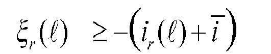


- As the objective function is quadratic subject to the evolution of the linear state-space prediction model with linear inequality constraints, the resulting optimization problem constitutes a so-called quadratic program (QP). The QP can be formulated and solved efficiently, e.g. by using an active set method or an interior point method. The result of the optimization stage is the sequence of optimal control inputs U = [u(k), u(k + 1),..., u(k + Np - 1)] at time step k.
- The first element of the sequence of optimal control inputs is implemented at time-step k and sent to the
modulators 36. At the next time-step k+1, new measurements are obtained and the optimization problem is solved again over a shiftedprediction horizon 40. This so-alled receding horizon policy provides feedback and ensures that thecontroller 18 is robust to parameter uncertainties. - The
second layer 28b of thehierarchical controller 18 may execute carrier-based pulse width modulation or space vector modulation or a related pulse width modulation method. The insertion index nr can be interpreted as the modulation index (reference voltage) of a multilevel pulse width modulation scheme. Themodulator 36 translates the real-valued reference voltage into the integer Nr which relates to the number ofconverter cells 22 to be inserted into therth branch 20. - For example, in case that an m-
level converter 16 is employed, then 2(m-1) carriers are needed.Fig. 9 shows a diagram for a 9-level converter with f c = 2. 5 kHz. - The carriers above zero are named as positive carriers while the carriers below zero as negative carriers. Each positive (negative) carrier is related to an extra positively (negatively) connected
converter cell 22. All the carriers have the same frequency fc and same peak-to-peak amplitude Ac and are disposed such that the bands they occupy to be contiguous. The branch insertion index nr is continuously compared with each of the carrier signals. The number of positive (negative) carriers that are lower (greater) than nr define the number Nr ofconverter cells 22 that must be positively (negatively) connected to thebranch 20. - In order to avoid multiple switching transitions within a carrier cycle, the regularly sample pulse width modulation method may be used. Specifically, the referenced insertion index per branch nr ∈[-1,1] is sampled every 5 kHz, at the point where the carrier reaches its peak or valley and it is continuously compared with the carrier waveforms. In that way, Nr ∈{-8, -7, ...,7, 8}, which serves as input to the balancing
controller 38, is being evaluated. - The
lower control layer 28c with the balancingcontrollers 38 utilizes a redundancy in the converter states to balance the capacitor voltages within thebranches 20 and minimizes the module switching frequency. - Each
branch 20 uses itsown balancing controller 38, which receives as input from the modulator the number of modules Nr to be inserted into the branch r. Thecontrollers 38 compute the switching signals for the converter cells, namely the switching signals [S 1 j, T 1j ], [S 2 j, T 2j ], [S 3 j, T 3j ], for the bottom and top IGBTs in the jth module. - While the invention has been illustrated and described in detail in the drawings and foregoing description, such illustration and description are to be considered illustrative or exemplary and not restrictive; the invention is not limited to the disclosed embodiments. Other variations to the disclosed embodiments can be understood and effected by those skilled in the art and practising the claimed invention, from a study of the drawings, the disclosure, and the appended claims. In the claims, the word "comprising" does not exclude other elements or steps, and the indefinite article "a" or "an" does not exclude a plurality. A single processor or controller or other unit may fulfil the functions of several items recited in the claims. The mere fact that certain measures are recited in mutually different dependent claims does not indicate that a combination of these measures cannot be used to advantage. Any reference signs in the claims should not be construed as limiting the scope.
-
- 10
- overall system (including converter, grid and load)
- 12
- electrical grid
- 14
- electrical load
- 16
- modular converter
- 18
- controller
- 20
- converter branch
- 22
- converter cell
- 24
- cell capacitor
- 26
- semiconductor switch
- 28a
- first control layer
- 28b
- second control layer
- 28c
- third control layer
- 30
- active power balancing control loop
- 32
- load current predictor
- 34
- model predictive control module
- 36
- pulse width modulator
- 38
- balancing controller
- 40
- prediction horizon
- 42
- soft constraint
Claims (15)
- A method for controlling a modular converter (16) connected to an electrical grid (12) for active power filtering the electrical grid (12) to compensate for a load (14) connected to the electrical grid (12), the method comprising:receiving an actual load current (il) and an actual converter state (x) of the modular converter (16);determining, from the actual load current and a history of previous load currents, a sequence of future load currents over a prediction horizon (40);predicting a sequence of future converter states of the modular converter (16) and a sequence of manipulated variables (U) for the modular converter (16) over the prediction horizon (40) by solving an optimization problem based on the actual converter state (x) and the future load currents by minimizing an objective function mapping control objectives to a scalar performance index subject to the dynamical evolution of a prediction model of the modular converter (16) and subject to constraints (42);applying a next switching state, which is determined from a first element of the sequence of manipulated variables (U), to the modular converter (16).
- The method of claim 1,
wherein the sequence of future load currents is determined by:determining phases, amplitudes and frequencies of a fundamental waveform and of harmonics of the actual and the history of load currents;predicting the evolution of the fundamental waveform and the harmonics with the determined phases, amplitudes and frequencies over the prediction horizon (40). - The method of claim 1 or 2, further comprising:wherein the sequence of future converter states is predicted based on a modified reference grid current


- The method of one of the preceding claims,
wherein the actual converter state and/or future converter states comprise branch voltages and/or branch currents of the modular converter (16). - The method of one of the preceding claims,
wherein the manipulated variable is a real-valued insertion index (nr), indicating how many converter cells (22) of the modular converter (16) are to be connected to a converter branch (20). - The method of claim 5,
wherein a discrete-valued insertion index (Nr) is determined from the real-valued insertion index by pulse width modulation. - The method of one of the preceding claims,
wherein a next switching state, indicating which converter cells (22) are to be connected to a converter branch (20), is determined from a next manipulated variable, such that capacitor voltages of the converter cells (22) are balanced in the converter branch (20). - The method of one of the preceding claims,
wherein the objective function is a quadratic function, which minimizes a change of the manipulated variable over the prediction horizon (40) and/or which minimizes deviations of controlled variables from their references. - The method of one of the preceding claims,
wherein the objective function comprises a term penalizing a magnitude of branch currents to minimize conduction and switching losses; and/or
wherein the objective function comprises a term penalizing a capacitor voltage ripple to minimize losses in cell capacitors and/or to reduce a size of cell capacitors. - The method of one of the preceding claims,
wherein the prediction model is solved subject to a hard constraint based on an inequality to be obeyed, when solving the optimization problem; and/or
wherein the optimization problem is solved subject to a soft constraint (42) based on a soft constraint term added to the objective function, which maps a violation of a soft inequality constraint into a number. - A controller (18), which is adapted for executing the method of one of the preceding claims.
- A computer program, which, when executed by a processor, is adapted for executing the method of one of claims 1 to 10.
- A computer-readable medium, on which a computer program according to claim 12 is stored.
- A converter system (10), comprising:a modular converter (16) connectable to an electrical grid (12), wherein the modular converter (16) comprises at least one converter branch (20), which comprises at least two series connected converter cells (22),a controller (18) according to claim 11 for controlling the modular converter (16).
- The converter system (10) of claim 14,
wherein the converter (16) comprises star-connected converter branches (20); or wherein the converter (16) comprises double star-connected converter branches (20); or
wherein the converter (16) comprises delta-connected converter branches (20).
Priority Applications (5)
| Application Number | Priority Date | Filing Date | Title |
|---|---|---|---|
| EP14178048.6A EP2978122A1 (en) | 2014-07-22 | 2014-07-22 | Model predictive control of a modular multilevel converter |
| PCT/EP2015/066312 WO2016012347A1 (en) | 2014-07-22 | 2015-07-16 | Model predictive control of a modular multilevel converter |
| CA2955908A CA2955908C (en) | 2014-07-22 | 2015-07-16 | Model predictive control of a modular multilevel converter |
| EP15738636.8A EP3195462A1 (en) | 2014-07-22 | 2015-07-16 | Model predictive control of a modular multilevel converter |
| US15/413,125 US10074978B2 (en) | 2014-07-22 | 2017-01-23 | Model predictive control of a modular multilevel converter |
Applications Claiming Priority (1)
| Application Number | Priority Date | Filing Date | Title |
|---|---|---|---|
| EP14178048.6A EP2978122A1 (en) | 2014-07-22 | 2014-07-22 | Model predictive control of a modular multilevel converter |
Publications (1)
| Publication Number | Publication Date |
|---|---|
| EP2978122A1 true EP2978122A1 (en) | 2016-01-27 |
Family
ID=51211685
Family Applications (2)
| Application Number | Title | Priority Date | Filing Date |
|---|---|---|---|
| EP14178048.6A Withdrawn EP2978122A1 (en) | 2014-07-22 | 2014-07-22 | Model predictive control of a modular multilevel converter |
| EP15738636.8A Ceased EP3195462A1 (en) | 2014-07-22 | 2015-07-16 | Model predictive control of a modular multilevel converter |
Family Applications After (1)
| Application Number | Title | Priority Date | Filing Date |
|---|---|---|---|
| EP15738636.8A Ceased EP3195462A1 (en) | 2014-07-22 | 2015-07-16 | Model predictive control of a modular multilevel converter |
Country Status (4)
| Country | Link |
|---|---|
| US (1) | US10074978B2 (en) |
| EP (2) | EP2978122A1 (en) |
| CA (1) | CA2955908C (en) |
| WO (1) | WO2016012347A1 (en) |
Cited By (20)
| Publication number | Priority date | Publication date | Assignee | Title |
|---|---|---|---|---|
| CN106301056A (en) * | 2016-09-28 | 2017-01-04 | 温州大学 | Multiple-objection optimization SVPWM method for MW class three-phase inversion system |
| CN106707752A (en) * | 2016-12-21 | 2017-05-24 | 大连理工大学 | Improved algorithm for solving state feedback gain matrix of current source STATCOM (static synchronous compensator) |
| CN107017812A (en) * | 2017-05-15 | 2017-08-04 | 广西大学 | The device and control method of a kind of self-excitation asynchronous generator |
| EP3220530A1 (en) * | 2016-03-15 | 2017-09-20 | Gamesa Innovation & Technology, S.L. | A three phase medium voltage power conversion system for closed-loop applications |
| CN107196540A (en) * | 2017-07-20 | 2017-09-22 | 云南电网有限责任公司电力科学研究院 | A kind of modularization multi-level converter direct current harmonic suppressing method |
| CN107769595A (en) * | 2017-11-21 | 2018-03-06 | 中国矿业大学 | A kind of three-level PWM rectifier model predictive control method |
| WO2018057818A1 (en) * | 2016-09-21 | 2018-03-29 | University Of Vermont And State Agricultural College | Systems and methods for randomized, packet-based power management of conditionally-controlled loads and bi-directional distributed energy storage systems |
| CN109327130A (en) * | 2018-10-26 | 2019-02-12 | 南方电网科学研究院有限责任公司 | Single-stage chained energy storage converter control method, device, equipment and storage medium |
| CN109565246A (en) * | 2016-07-05 | 2019-04-02 | 超级电力研究所有限公司 | For controlling the module of the internal energy of converter |
| CN110149066A (en) * | 2019-05-16 | 2019-08-20 | 华中科技大学 | A kind of MMC bridge arm current control method and system based on model cootrol prediction |
| CN111541262A (en) * | 2020-05-12 | 2020-08-14 | 浙江大学 | MMC frequency coupling impedance modeling method under control of model pre-determination alternating voltage |
| EP3722896A1 (en) * | 2019-04-11 | 2020-10-14 | Hamilton Sundstrand Corporation | Model predictive control for matrix converter operating in current control mode with load current estimation |
| WO2021038246A1 (en) * | 2019-08-30 | 2021-03-04 | Sajjad Fekriasl | Method of submodule switching control in modular multilevel converters |
| CN112701895A (en) * | 2021-01-27 | 2021-04-23 | 徐州送变电有限公司 | Improved control strategy of MMC (modular multilevel converter) during single-phase earth fault based on model prediction |
| US11150618B2 (en) | 2016-09-21 | 2021-10-19 | University Of Vermont And State Agricultural College | Packetized energy management control systems and methods of using the same |
| US11171484B2 (en) | 2013-03-04 | 2021-11-09 | University Of Vermont And State Agricultural College | Systems and methods for random-access power management |
| CN114400910A (en) * | 2022-01-17 | 2022-04-26 | 燕山大学 | Multi-step prediction control method of current source type converter based on vector advance screening |
| CN115276120A (en) * | 2022-08-23 | 2022-11-01 | 山东大学 | Model-free predictive control method and system for power converter |
| CN116131644A (en) * | 2022-11-25 | 2023-05-16 | 天津大学 | Modulation type double-layer model prediction control method and device for multi-level converter |
| CN116707331A (en) * | 2023-08-02 | 2023-09-05 | 中国人民解放军空军预警学院 | Inverter output voltage high-precision adjusting method and system based on model prediction |
Families Citing this family (30)
| Publication number | Priority date | Publication date | Assignee | Title |
|---|---|---|---|---|
| EP3196713B2 (en) * | 2016-01-19 | 2024-06-26 | dSPACE GmbH | Device for simulation |
| WO2018033214A1 (en) * | 2016-08-18 | 2018-02-22 | Abb Schweiz Ag | Modulation of ac/ac mmc |
| DE102017211690B4 (en) | 2017-07-07 | 2020-07-16 | Bayerische Motoren Werke Aktiengesellschaft | System for reducing load peaks in an electrical system |
| US11487253B2 (en) | 2017-09-15 | 2022-11-01 | Universidad Andres Bello | Method for sequential predictive control, first solving a cost function and subsequently a second cost function for two or more control objectives |
| CN107611990B (en) * | 2017-09-27 | 2020-08-25 | 西安翌飞核能装备股份有限公司 | Chained STATCOM DC total voltage control method with voltage ride through capability |
| EP3496261B1 (en) * | 2017-12-07 | 2023-11-22 | ABB Schweiz AG | Control and modulation of a converter |
| CN111587529B (en) * | 2018-01-11 | 2024-02-23 | Abb瑞士股份有限公司 | Model predictive control of pulse width modulation switching mode based converters |
| EP3614218B1 (en) | 2018-08-22 | 2022-04-06 | Technische Hochschule Nuernberg Georg-Simon-Ohm | Cascaded continuous and finite model predictive control for mechatronic systems |
| CN109659954B (en) * | 2019-01-29 | 2022-07-01 | 西北工业大学 | Sequencing model prediction control method of chain type STATCOM |
| KR102275748B1 (en) * | 2019-06-12 | 2021-07-13 | 중앙대학교 산학협력단 | The control system and method of mmc converter |
| CN110380397B (en) * | 2019-06-18 | 2022-12-23 | 天津大学 | Control framework suitable for medium-low voltage direct current power distribution and utilization system |
| CN110244567B (en) * | 2019-07-04 | 2021-09-24 | 武汉大学 | Rapid model prediction control method based on extended instantaneous reactive power theory |
| US11515818B2 (en) * | 2020-03-25 | 2022-11-29 | King Fahd University Of Petroleum And Minerals | Common-mode voltage reduction of a SiC based dual T-type drive system |
| CN111725832B (en) * | 2020-06-05 | 2022-02-22 | 西安交通大学 | Direct-current side voltage indirect control method of multi-terminal flexible power transmission system based on simplified offline algorithm |
| CN111737872B (en) * | 2020-06-24 | 2022-08-19 | 山东大学 | Margin prediction control method and system based on magnetic characteristics of passive component |
| CN112467788B (en) * | 2020-11-18 | 2023-03-10 | 西安热工研究院有限公司 | Method for reducing steady-state error of photovoltaic model predictive control system during low voltage ride through |
| CN112910295B (en) * | 2021-01-20 | 2022-05-20 | 山东大学 | Zero-time-delay multi-vector model prediction control method and system for three-phase multi-level inverter |
| CN113193544B (en) * | 2021-04-12 | 2023-07-14 | 唐山冀东石油机械有限责任公司 | DC micro-grid group power optimization strategy based on PWM model prediction |
| CN113193759B (en) * | 2021-04-16 | 2022-06-21 | 山东大学苏州研究院 | High-power four-quadrant converter fault-tolerant control method based on predictive control |
| CN113346777B (en) * | 2021-04-28 | 2024-04-02 | 西安交通大学 | PI passive control method and system for modularized multi-level converter |
| EP4109699B1 (en) * | 2021-06-25 | 2024-07-24 | General Electric Technology GmbH | Improvements in or relating to stability and power control in multiphase ac networks |
| CN113675888B (en) * | 2021-08-26 | 2022-09-16 | 山东大学 | Converter cascade prediction control method and system based on accurate discretization |
| CN113644834B (en) * | 2021-10-14 | 2022-02-15 | 广东电网有限责任公司珠海供电局 | Loss assessment method and system for modular multilevel converter |
| CN114157171B (en) * | 2021-12-07 | 2022-06-28 | 中国矿业大学(北京) | Improved model prediction current control method based on thermal management |
| CN114244160A (en) * | 2021-12-23 | 2022-03-25 | 湘潭大学 | Model prediction control method for isolated AC-DC matrix converter |
| US20230231388A1 (en) * | 2022-01-14 | 2023-07-20 | Schweitzer Engineering Laboratories, Inc. | Linearized-trajectory predictive control for microgrid stability |
| WO2023230897A1 (en) * | 2022-05-31 | 2023-12-07 | 西门子股份公司 | Mmc control method and control apparatus, computing device and storage medium |
| CN115765508A (en) * | 2022-11-25 | 2023-03-07 | 天津大学 | Prediction control method for equivalent space vector model of modular multilevel converter |
| CN117955167A (en) * | 2023-05-29 | 2024-04-30 | 南京南瑞继保电气有限公司 | Network-structured voltage source converter system and multi-target control method |
| CN117492371B (en) * | 2023-12-29 | 2024-04-02 | 中国科学院合肥物质科学研究院 | Optimization method, system and equipment for active power filter model predictive control |
Citations (2)
| Publication number | Priority date | Publication date | Assignee | Title |
|---|---|---|---|---|
| WO2014006200A1 (en) * | 2012-07-06 | 2014-01-09 | Abb Technology Ag | Controlling a modular converter |
| WO2014033155A1 (en) | 2012-08-28 | 2014-03-06 | Abb Technology Ag | Controlling a modular converter in two stages |
Family Cites Families (4)
| Publication number | Priority date | Publication date | Assignee | Title |
|---|---|---|---|---|
| KR100886194B1 (en) * | 2007-06-08 | 2009-02-27 | 한국전기연구원 | Controller of double-fed induction generator |
| EP2602629A4 (en) * | 2010-08-02 | 2017-07-05 | Panasonic Corporation | Distributed power supply system and control method thereof |
| CN103296908B (en) * | 2012-03-02 | 2015-08-26 | 台达电子企业管理(上海)有限公司 | Multiple inverter and Active Power Filter-APF |
| US10931190B2 (en) * | 2015-10-22 | 2021-02-23 | Inertech Ip Llc | Systems and methods for mitigating harmonics in electrical systems by using active and passive filtering techniques |
-
2014
- 2014-07-22 EP EP14178048.6A patent/EP2978122A1/en not_active Withdrawn
-
2015
- 2015-07-16 CA CA2955908A patent/CA2955908C/en active Active
- 2015-07-16 EP EP15738636.8A patent/EP3195462A1/en not_active Ceased
- 2015-07-16 WO PCT/EP2015/066312 patent/WO2016012347A1/en active Application Filing
-
2017
- 2017-01-23 US US15/413,125 patent/US10074978B2/en active Active
Patent Citations (2)
| Publication number | Priority date | Publication date | Assignee | Title |
|---|---|---|---|---|
| WO2014006200A1 (en) * | 2012-07-06 | 2014-01-09 | Abb Technology Ag | Controlling a modular converter |
| WO2014033155A1 (en) | 2012-08-28 | 2014-03-06 | Abb Technology Ag | Controlling a modular converter in two stages |
Non-Patent Citations (4)
| Title |
|---|
| BALJIT S RIAR ET AL: "Model Predictive Direct Current Control of Modular Multi-level Converters", INDUSTRIAL TECHNOLOGY (ICIT), 2013 IEEE INTERNATIONAL CONFERENCE ON, IEEE, 25 February 2013 (2013-02-25), pages 582 - 587, XP032377162, ISBN: 978-1-4673-4567-5, DOI: 10.1109/ICIT.2013.6505736 * |
| CORTES P ET AL: "Model Predictive Control of Cascaded H-Bridge multilevel inverters", 13TH EUROPEAN CONFERENCE ON POWER ELECTRONICS AND APPLICATIONS, 2009 : EPE '09 ; 8 - 10 SEPT. 2009, BARCELONA, SPAIN, IEEE, PISCATAWAY, NJ, USA, 8 September 2009 (2009-09-08), pages 1 - 9, XP031541520, ISBN: 978-1-4244-4432-8 * |
| DANIEL E. QUEVEDO ET AL: "Finite constraint set receding horizon quadratic control", INTERNATIONAL JOURNAL OF ROBUST AND NONLINEAR CONTROL, vol. 14, no. 4, 10 March 2004 (2004-03-10), pages 355 - 377, XP055162467, ISSN: 1049-8923, DOI: 10.1002/rnc.887 * |
| MENDALEK N ET AL: "A non-linear optimal predictive control of a shunt active power filter", CONFERENCE RECORD OF THE 2002 IEEE INDUSTRY APPLICATIONS CONFERENCE : 37TH IAS ANNUAL MEETING ; 13 - 18 OCTOBER 2002, PITTSBURGH, PENNSYLVANIA, USA; [CONFERENCE RECORD OF THE IEEE INDUSTRY APPLICATIONS CONFERENCE. IAS ANNUAL MEETING], IEEE SERVICE CE, 13 October 2002 (2002-10-13), pages 70 - 77vol.1, XP032143413, ISBN: 978-0-7803-7420-1, DOI: 10.1109/IAS.2002.1044069 * |
Cited By (31)
| Publication number | Priority date | Publication date | Assignee | Title |
|---|---|---|---|---|
| US11171484B2 (en) | 2013-03-04 | 2021-11-09 | University Of Vermont And State Agricultural College | Systems and methods for random-access power management |
| EP3220530A1 (en) * | 2016-03-15 | 2017-09-20 | Gamesa Innovation & Technology, S.L. | A three phase medium voltage power conversion system for closed-loop applications |
| CN109565246B (en) * | 2016-07-05 | 2021-11-12 | 超级电力研究所有限公司 | Module for controlling the internal energy of a converter |
| CN109565246A (en) * | 2016-07-05 | 2019-04-02 | 超级电力研究所有限公司 | For controlling the module of the internal energy of converter |
| US11210747B2 (en) | 2016-09-21 | 2021-12-28 | University Of Vermont And State Agricultural College | Systems and methods for randomized, packet-based power management of conditionally-controlled loads and bi-directional distributed energy storage systems |
| US11150618B2 (en) | 2016-09-21 | 2021-10-19 | University Of Vermont And State Agricultural College | Packetized energy management control systems and methods of using the same |
| WO2018057818A1 (en) * | 2016-09-21 | 2018-03-29 | University Of Vermont And State Agricultural College | Systems and methods for randomized, packet-based power management of conditionally-controlled loads and bi-directional distributed energy storage systems |
| US11972496B2 (en) | 2016-09-21 | 2024-04-30 | University Of Vermont And State Agricultural College | Systems and methods for randomized energy draw or supply requests |
| CN106301056A (en) * | 2016-09-28 | 2017-01-04 | 温州大学 | Multiple-objection optimization SVPWM method for MW class three-phase inversion system |
| CN106707752A (en) * | 2016-12-21 | 2017-05-24 | 大连理工大学 | Improved algorithm for solving state feedback gain matrix of current source STATCOM (static synchronous compensator) |
| CN107017812A (en) * | 2017-05-15 | 2017-08-04 | 广西大学 | The device and control method of a kind of self-excitation asynchronous generator |
| CN107017812B (en) * | 2017-05-15 | 2019-06-25 | 广西大学 | A kind of device and control method of self-excitation asynchronous generator |
| CN107196540A (en) * | 2017-07-20 | 2017-09-22 | 云南电网有限责任公司电力科学研究院 | A kind of modularization multi-level converter direct current harmonic suppressing method |
| CN107196540B (en) * | 2017-07-20 | 2019-03-12 | 云南电网有限责任公司电力科学研究院 | A kind of modularization multi-level converter direct current harmonic suppressing method |
| CN107769595A (en) * | 2017-11-21 | 2018-03-06 | 中国矿业大学 | A kind of three-level PWM rectifier model predictive control method |
| CN109327130A (en) * | 2018-10-26 | 2019-02-12 | 南方电网科学研究院有限责任公司 | Single-stage chained energy storage converter control method, device, equipment and storage medium |
| EP3722896A1 (en) * | 2019-04-11 | 2020-10-14 | Hamilton Sundstrand Corporation | Model predictive control for matrix converter operating in current control mode with load current estimation |
| US11290023B2 (en) | 2019-04-11 | 2022-03-29 | Hamilton Sundstrand Corporation | Model predictive control for matrix converter operating in current control mode with load current estimation |
| CN110149066B (en) * | 2019-05-16 | 2020-05-19 | 华中科技大学 | MMC bridge arm current control method and system based on model control prediction |
| CN110149066A (en) * | 2019-05-16 | 2019-08-20 | 华中科技大学 | A kind of MMC bridge arm current control method and system based on model cootrol prediction |
| WO2021038246A1 (en) * | 2019-08-30 | 2021-03-04 | Sajjad Fekriasl | Method of submodule switching control in modular multilevel converters |
| CN111541262A (en) * | 2020-05-12 | 2020-08-14 | 浙江大学 | MMC frequency coupling impedance modeling method under control of model pre-determination alternating voltage |
| CN112701895A (en) * | 2021-01-27 | 2021-04-23 | 徐州送变电有限公司 | Improved control strategy of MMC (modular multilevel converter) during single-phase earth fault based on model prediction |
| CN114400910B (en) * | 2022-01-17 | 2022-08-16 | 燕山大学 | Multi-step prediction control method of current source type converter based on vector advance screening |
| CN114400910A (en) * | 2022-01-17 | 2022-04-26 | 燕山大学 | Multi-step prediction control method of current source type converter based on vector advance screening |
| CN115276120A (en) * | 2022-08-23 | 2022-11-01 | 山东大学 | Model-free predictive control method and system for power converter |
| CN115276120B (en) * | 2022-08-23 | 2023-05-30 | 山东大学 | Model-free predictive control method and system for power converter |
| CN116131644A (en) * | 2022-11-25 | 2023-05-16 | 天津大学 | Modulation type double-layer model prediction control method and device for multi-level converter |
| CN116131644B (en) * | 2022-11-25 | 2024-03-15 | 天津大学 | Modulation type double-layer model prediction control method and device for multi-level converter |
| CN116707331A (en) * | 2023-08-02 | 2023-09-05 | 中国人民解放军空军预警学院 | Inverter output voltage high-precision adjusting method and system based on model prediction |
| CN116707331B (en) * | 2023-08-02 | 2023-10-20 | 中国人民解放军空军预警学院 | Inverter output voltage high-precision adjusting method and system based on model prediction |
Also Published As
| Publication number | Publication date |
|---|---|
| US20170133845A1 (en) | 2017-05-11 |
| EP3195462A1 (en) | 2017-07-26 |
| WO2016012347A1 (en) | 2016-01-28 |
| CA2955908A1 (en) | 2016-01-28 |
| CA2955908C (en) | 2023-05-02 |
| US10074978B2 (en) | 2018-09-11 |
Similar Documents
| Publication | Publication Date | Title |
|---|---|---|
| US10074978B2 (en) | Model predictive control of a modular multilevel converter | |
| Riar et al. | Model predictive direct current control of modular multilevel converters: Modeling, analysis, and experimental evaluation | |
| Townsend et al. | Multigoal heuristic model predictive control technique applied to a cascaded H-bridge StatCom | |
| EP2131480B1 (en) | Midpoint current and voltage regulation of a multi-level converter | |
| US9590530B2 (en) | Controlling a modular converter in two stages | |
| Chebabhi et al. | A new balancing three level three dimensional space vector modulation strategy for three level neutral point clamped four leg inverter based shunt active power filter controlling by nonlinear back stepping controllers | |
| Aissa et al. | Analysis and experimental evaluation of shunt active power filter for power quality improvement based on predictive direct power control | |
| EP3806311B1 (en) | Model predictive pulse pattern control based on small-signal pulse pattern optimization | |
| Darivianakis et al. | Model predictive current control of modular multilevel converters | |
| Konstantinou et al. | Estimation methods and sensor reduction in modular multilevel converters: A review | |
| Abou Houran et al. | Active power filter module function to improve power quality conditions using GWO and PSO techniques for solar photovoltaic arrays and battery energy storage systems | |
| Zafari et al. | A robust fractional-order control technique for stable performance of multilevel converter-based grid-tied DG units | |
| Rodriguez et al. | Constrained control of low-capacitance delta cascaded H-bridge StatComs: A model predictive control approach | |
| Geyer et al. | Model predictive control of a STATCOM based on a modular multilevel converter in delta configuration | |
| González-Torres et al. | Long-length horizons dynamic matrix predictive control for a MMC inverter | |
| Chaijarurnudomrung et al. | The controller design of three-phase controlled rectifier using an adaptive tabu search algorithm | |
| Radmanesh et al. | Linear Modelling of Six Pulse Rectifier and Designee of Model Predictive Controller with Stability Analysis | |
| Wang et al. | Control of input current harmonics and output voltage of three-phase voltage source PWM rectifier using Model Predictive Control | |
| Ruiz et al. | Controllability of rectifiers and three point hysteresis line current control | |
| Fukuda et al. | Neutral point potential and unity power factor control of NPC boost converters | |
| Božiček et al. | Time–optimal current control with constant switching frequency for STATCOM | |
| Jiang et al. | Improved multistep model predictive control method with reduced finite set for MMC-UPQC | |
| Freire et al. | Model Predictive Control of a five-level Neutral-Point-Clamped STATCOM | |
| Tariquzzaman | Finite-State Predictive Current Control of a Simplified Three-Level Neutral-Point Clamped Inverter | |
| Townsend | Control and modulation strategies for a multi-level h-bridge statcom |
Legal Events
| Date | Code | Title | Description |
|---|---|---|---|
| PUAI | Public reference made under article 153(3) epc to a published international application that has entered the european phase |
Free format text: ORIGINAL CODE: 0009012 |
|
| AK | Designated contracting states |
Kind code of ref document: A1 Designated state(s): AL AT BE BG CH CY CZ DE DK EE ES FI FR GB GR HR HU IE IS IT LI LT LU LV MC MK MT NL NO PL PT RO RS SE SI SK SM TR |
|
| AX | Request for extension of the european patent |
Extension state: BA ME |
|
| STAA | Information on the status of an ep patent application or granted ep patent |
Free format text: STATUS: THE APPLICATION IS DEEMED TO BE WITHDRAWN |
|
| 18D | Application deemed to be withdrawn |
Effective date: 20160728 |