EP2977994A1 - Wire and coil - Google Patents
Wire and coil Download PDFInfo
- Publication number
- EP2977994A1 EP2977994A1 EP14770299.7A EP14770299A EP2977994A1 EP 2977994 A1 EP2977994 A1 EP 2977994A1 EP 14770299 A EP14770299 A EP 14770299A EP 2977994 A1 EP2977994 A1 EP 2977994A1
- Authority
- EP
- European Patent Office
- Prior art keywords
- electric wire
- wire
- copper
- resistance
- coil
- Prior art date
- Legal status (The legal status is an assumption and is not a legal conclusion. Google has not performed a legal analysis and makes no representation as to the accuracy of the status listed.)
- Withdrawn
Links
- RYGMFSIKBFXOCR-UHFFFAOYSA-N Copper Chemical compound [Cu] RYGMFSIKBFXOCR-UHFFFAOYSA-N 0.000 claims abstract description 89
- 239000010949 copper Substances 0.000 claims abstract description 76
- 229910052802 copper Inorganic materials 0.000 claims abstract description 53
- 239000000126 substance Substances 0.000 claims abstract description 8
- 239000004020 conductor Substances 0.000 claims description 24
- 239000000463 material Substances 0.000 claims description 24
- 230000005291 magnetic effect Effects 0.000 claims description 16
- 238000000034 method Methods 0.000 claims description 16
- 230000035699 permeability Effects 0.000 claims description 5
- 229910052782 aluminium Inorganic materials 0.000 description 22
- XAGFODPZIPBFFR-UHFFFAOYSA-N aluminium Chemical compound [Al] XAGFODPZIPBFFR-UHFFFAOYSA-N 0.000 description 20
- 230000000694 effects Effects 0.000 description 11
- 230000002500 effect on skin Effects 0.000 description 9
- 239000011135 tin Substances 0.000 description 6
- ATJFFYVFTNAWJD-UHFFFAOYSA-N Tin Chemical compound [Sn] ATJFFYVFTNAWJD-UHFFFAOYSA-N 0.000 description 5
- 229910052718 tin Inorganic materials 0.000 description 5
- 229910000906 Bronze Inorganic materials 0.000 description 4
- OAICVXFJPJFONN-UHFFFAOYSA-N Phosphorus Chemical compound [P] OAICVXFJPJFONN-UHFFFAOYSA-N 0.000 description 4
- XUIMIQQOPSSXEZ-UHFFFAOYSA-N Silicon Chemical compound [Si] XUIMIQQOPSSXEZ-UHFFFAOYSA-N 0.000 description 4
- 239000010974 bronze Substances 0.000 description 4
- KUNSUQLRTQLHQQ-UHFFFAOYSA-N copper tin Chemical compound [Cu].[Sn] KUNSUQLRTQLHQQ-UHFFFAOYSA-N 0.000 description 4
- 229910052710 silicon Inorganic materials 0.000 description 4
- 239000010703 silicon Substances 0.000 description 4
- 238000004804 winding Methods 0.000 description 4
- 229910045601 alloy Inorganic materials 0.000 description 3
- 239000000956 alloy Substances 0.000 description 3
- 238000010411 cooking Methods 0.000 description 3
- 238000010438 heat treatment Methods 0.000 description 3
- 230000006698 induction Effects 0.000 description 3
- 229910052698 phosphorus Inorganic materials 0.000 description 3
- 239000011574 phosphorus Substances 0.000 description 3
- 229910000838 Al alloy Inorganic materials 0.000 description 2
- 229910021365 Al-Mg-Si alloy Inorganic materials 0.000 description 2
- 229910001369 Brass Inorganic materials 0.000 description 2
- 229910000881 Cu alloy Inorganic materials 0.000 description 2
- 239000010951 brass Substances 0.000 description 2
- 239000011651 chromium Substances 0.000 description 2
- 230000003247 decreasing effect Effects 0.000 description 2
- 238000001514 detection method Methods 0.000 description 2
- 230000004907 flux Effects 0.000 description 2
- 239000012212 insulator Substances 0.000 description 2
- 229910000952 Be alloy Inorganic materials 0.000 description 1
- VYZAMTAEIAYCRO-UHFFFAOYSA-N Chromium Chemical compound [Cr] VYZAMTAEIAYCRO-UHFFFAOYSA-N 0.000 description 1
- 229910017518 Cu Zn Inorganic materials 0.000 description 1
- 229910017752 Cu-Zn Inorganic materials 0.000 description 1
- 229910017943 Cu—Zn Inorganic materials 0.000 description 1
- 229910009038 Sn—P Inorganic materials 0.000 description 1
- 229910008813 Sn—Si Inorganic materials 0.000 description 1
- HCHKCACWOHOZIP-UHFFFAOYSA-N Zinc Chemical compound [Zn] HCHKCACWOHOZIP-UHFFFAOYSA-N 0.000 description 1
- ZUPBPXNOBDEWQT-UHFFFAOYSA-N [Si].[Ni].[Cu] Chemical compound [Si].[Ni].[Cu] ZUPBPXNOBDEWQT-UHFFFAOYSA-N 0.000 description 1
- 229910052804 chromium Inorganic materials 0.000 description 1
- 239000011248 coating agent Substances 0.000 description 1
- 238000000576 coating method Methods 0.000 description 1
- 239000012141 concentrate Substances 0.000 description 1
- 239000000470 constituent Substances 0.000 description 1
- TVZPLCNGKSPOJA-UHFFFAOYSA-N copper zinc Chemical compound [Cu].[Zn] TVZPLCNGKSPOJA-UHFFFAOYSA-N 0.000 description 1
- 230000007423 decrease Effects 0.000 description 1
- 238000006073 displacement reaction Methods 0.000 description 1
- 238000009472 formulation Methods 0.000 description 1
- 230000020169 heat generation Effects 0.000 description 1
- 239000000696 magnetic material Substances 0.000 description 1
- 238000004519 manufacturing process Methods 0.000 description 1
- 239000000203 mixture Substances 0.000 description 1
- 238000007747 plating Methods 0.000 description 1
- 239000011347 resin Substances 0.000 description 1
- 229920005989 resin Polymers 0.000 description 1
- 229910021484 silicon-nickel alloy Inorganic materials 0.000 description 1
- 238000005476 soldering Methods 0.000 description 1
- JBQYATWDVHIOAR-UHFFFAOYSA-N tellanylidenegermanium Chemical compound [Te]=[Ge] JBQYATWDVHIOAR-UHFFFAOYSA-N 0.000 description 1
- 229910052725 zinc Inorganic materials 0.000 description 1
- 239000011701 zinc Substances 0.000 description 1
Images




Classifications
-
- H—ELECTRICITY
- H01—ELECTRIC ELEMENTS
- H01B—CABLES; CONDUCTORS; INSULATORS; SELECTION OF MATERIALS FOR THEIR CONDUCTIVE, INSULATING OR DIELECTRIC PROPERTIES
- H01B1/00—Conductors or conductive bodies characterised by the conductive materials; Selection of materials as conductors
- H01B1/02—Conductors or conductive bodies characterised by the conductive materials; Selection of materials as conductors mainly consisting of metals or alloys
- H01B1/026—Alloys based on copper
-
- H—ELECTRICITY
- H01—ELECTRIC ELEMENTS
- H01B—CABLES; CONDUCTORS; INSULATORS; SELECTION OF MATERIALS FOR THEIR CONDUCTIVE, INSULATING OR DIELECTRIC PROPERTIES
- H01B1/00—Conductors or conductive bodies characterised by the conductive materials; Selection of materials as conductors
- H01B1/02—Conductors or conductive bodies characterised by the conductive materials; Selection of materials as conductors mainly consisting of metals or alloys
-
- H—ELECTRICITY
- H01—ELECTRIC ELEMENTS
- H01B—CABLES; CONDUCTORS; INSULATORS; SELECTION OF MATERIALS FOR THEIR CONDUCTIVE, INSULATING OR DIELECTRIC PROPERTIES
- H01B7/00—Insulated conductors or cables characterised by their form
- H01B7/30—Insulated conductors or cables characterised by their form with arrangements for reducing conductor losses when carrying alternating current, e.g. due to skin effect
-
- H—ELECTRICITY
- H01—ELECTRIC ELEMENTS
- H01F—MAGNETS; INDUCTANCES; TRANSFORMERS; SELECTION OF MATERIALS FOR THEIR MAGNETIC PROPERTIES
- H01F27/00—Details of transformers or inductances, in general
- H01F27/28—Coils; Windings; Conductive connections
- H01F27/2823—Wires
-
- H—ELECTRICITY
- H01—ELECTRIC ELEMENTS
- H01F—MAGNETS; INDUCTANCES; TRANSFORMERS; SELECTION OF MATERIALS FOR THEIR MAGNETIC PROPERTIES
- H01F5/00—Coils
-
- H—ELECTRICITY
- H02—GENERATION; CONVERSION OR DISTRIBUTION OF ELECTRIC POWER
- H02K—DYNAMO-ELECTRIC MACHINES
- H02K3/00—Details of windings
- H02K3/02—Windings characterised by the conductor material
-
- H—ELECTRICITY
- H05—ELECTRIC TECHNIQUES NOT OTHERWISE PROVIDED FOR
- H05B—ELECTRIC HEATING; ELECTRIC LIGHT SOURCES NOT OTHERWISE PROVIDED FOR; CIRCUIT ARRANGEMENTS FOR ELECTRIC LIGHT SOURCES, IN GENERAL
- H05B6/00—Heating by electric, magnetic or electromagnetic fields
- H05B6/02—Induction heating
- H05B6/36—Coil arrangements
Definitions
- the present invention relates to an electric wire and a coil used in high frequency.
- countermeasure is made by thinning an outer diameter of the electric wire and employing a litz wire with insulating coating (for example, refer to Patent Documents 1 to 5).
- Patent Document 6 Although the frequency range where the AC resistance is equal to or less than the copper wire is defined, the value of the frequency itself is not defined. Therefore, when designing the electric wire or the coil, a determination whether the AC resistance can be equal to or less than the copper wire at a frequency to be used may be complicated, and in some cases, the design of the electric wire and the coil may be difficult.
- an object of the present invention is to provide an electric wire and a coil capable of reducing the AC resistance equal to or less than the copper wire and being easily designed, and a design method of the electric wire capable of easily designing the electric wire.
- An aspect of the present invention provides an electric wire including a single layered structure having a first layer of a substance having lower conductivity than copper, or including a double layered structure in which a second layer of copper is formed on a periphery of the first layer, wherein a radius of the electric wire is less than a skin depth, an alternating current resistance value of the electric wire at a frequency used in the electric wire is provided in excess of a sum of a value obtained by multiplying a direct current resistance value of the electric wire by a ratio of a cross-sectional area of the first layer and a cross-sectional area of the entire electric wire, and a direct current resistance value of a copper wire having a same shape and a same outer diameter as the electric wire.
- Another aspect of the present invention provides a coil using an electric wire including a single layered structure having a first layer of a substance having lower conductivity than copper, or including a double layered structure in which a second layer of copper is formed on a periphery of the first layer, wherein a radius of the electric wire is less than a skin depth, an alternating current resistance value of the electric wire at a frequency used in the electric wire is provided in excess of a sum of a value obtained by multiplying a direct current resistance value of the electric wire by a ratio of a cross-sectional area of the first layer and a cross-sectional area of the entire electric wire, and a direct current resistance value of a copper wire having a same shape and a same outer diameter as the electric wire.
- Still another aspect of the present invention provides a method for designing an electric wire including using a wire material including a single layered structure having a first layer of a substance having lower conductivity than copper, or including a double-layered structure in which a second layer of copper is formed on a periphery of the first layer; designing the electric wire so that a radius of the electric wire is smaller than a skin depth thereof, and an alternating current resistance value of the electric wire at a frequency used in the electric wire is in excess of a sum of a value obtained by multiplying a direct current resistance value of the electric wire by a ratio of a cross-sectional area of the first layer and a cross-sectional area of the entire electric wire, and a direct current resistance value of a copper wire having a same shape and a same outer diameter as the electric wire.
- an electric wire and a coil capable of reducing the AC resistance equal to or less than the copper wire and being easily designed, and a design method of the electric wire capable of easily designing the electric wire.
- An electric wire 1 according to a first embodiment of the present invention is made of a wire material having lower conductivity than copper where a radius a of the electric wire 1 is smaller than a skin depth thereof, and an AC resistance value of the electric wire 1 at a frequency used in the electric wire 1 is provided in excess of a sum of a direct current (DC) resistance value of the electric wire 1 and a DC resistance value of the copper wire having the same shape and the same outer diameter as the electric wire 1.
- DC direct current
- the current density is largest at a conductor surface, and the current density exponentially decreases in a direction from the conductor surface to the conductor center. This is called the skin effect.
- the depth of a current density value obtained by multiplying the current density at the conductor surface by "1/e” is defined as “skin depth”. "e” is the base of natural logarithm, and 1/e is about 0.37. The higher the frequency of the AC current, the larger the current density at the conductor surface and the less the current density at the conductor center.
- the frequency used in the electric wire 1 according to the first embodiment of the present invention may be set as appropriate according to the specification of each product, and is not particularly limited. For example, it may be about 1 kHz to about 1 MHz, or about 10 kHz to about 100 kHz. In the case of the induction heating (IH) cooking device, it may be about 20 kHz to about 100 kHz. It may be about 50 Hz to about 60 Hz in the case of the product that directly uses the utility frequency in Japan, United State, Europe, China, and the like.
- IH induction heating
- the diameter of the electric wire 1 according to the first embodiment of the present invention is preferably about 0.05 mm to about 0.6 mm, and is not particularly limited.
- Copper alloy such as brass, phosphor bronze, silicon bronze, copper-beryllium alloys, copper-nickel-silicon alloy and the like, maybe used for the wire material constituting the electric wire 1.
- the brass is an alloy (Cu-Zn) containing copper (Cu) and zinc (Zn), and also may contain small amounts of elements other than copper and zinc.
- the silicon bronze is an alloy (Cu-Sn-Si) containing copper, tin (Sn) and silicon (Si), and also may contain small amounts of elements other than copper, tin and silicon.
- the phosphorus bronze (Cu-Sn-P) is an alloy containing copper, tin and phosphorus (P), and also may contain small amounts of elements other than copper, tin and phosphorus. These copper alloy wire may be subjected to tin, copper or chromium (Cr) plating. Moreover, the electric wire 1 may have a cylindrical shape, and also may have a various shape, such as a rectangular shape, and the like.
- a copper clad aluminum (CCA) wire in which copper (Cu) is uniformly coated on the outer circumference of an aluminum (Al) wire may be used.
- Overall diameter of the CCA wire which is preferably about 0.05 mm to about 0.6 mm, and is not particularly limited.
- a cross-sectional area of the copper layer is greater than 0 and not more than 30% with respect to the cross-sectional area of the entire electric wire which includes the aluminum wire and the copper layer, preferably about 3% to about 15%, more preferably about 3% to about 10%, further more preferably about 3% to about 5%.
- the AC resistance can be decreased.
- aluminum wire for example, aluminum for electric use (EC aluminum) or aluminum alloy, such as Al-Mg-Si alloy (JIS6000 series), may be used.
- eddy current may flow in the conductor by the magnetic flux in the conductor, and this eddy current may increase the AC resistance caused by a skin effect.
- eddy current may flow in the conductor by an external magnetic flux, and this eddy current may increase the AC resistance caused by a proximity effect.
- the AC resistance R ac per unit length of the electric wire or coil can be expressed by the following equation (1).
- R ac R s + R p
- R s is a resistance of an element wire per unit length includes the increase due to the skin effect
- Rp is a resistance of an element wire per unit length due to the proximity effect.
- R s and R p are expressed by the following equation (2) and (3).
- R s R j ⁇ 0 2 ⁇ ⁇ ka ⁇ J 0 ka J 0 ⁇ ka
- R p - 4 ⁇ ⁇ ⁇ ⁇ ⁇ 2
- k 2 - j ⁇ 0 ⁇ ⁇
- j is the imaginary unit
- ⁇ is the circular constant
- ⁇ is the angular frequency
- ⁇ 0 is the permeability of vacuum
- a is the radius of the element wire
- J n represents the first kind Bessel function of order n.
- ⁇ is a coefficient representing the intensity of the magnetic field acting on the element wire.
- Resistance of the coil or the electric wire is proportional to the length of the conductor forming the coil or the electric wire and inversely proportional to number of the element wires of the conductor constituting the coil or the electric wire.
- the AC resistance of the coil or the electric wire is represented by the following equation (5).
- T 1 in case of the electric wire in which the number of turns is one.
- the energy loss is represented by one-half product of resistance and square of the current, from the expression (5), the loss due to the proximity effect is expressed by the following equation (8). 1 2 ⁇ Ni 0 2 ⁇ R p ⁇ l N
- i 0 is the current in the element wire.
- H i can be obtained by calculation using the finite element method, or calculation using the Ampere law, and the like.
- the frequency f 1 and the AC resistance R 1 in this case are expressed by the following equations (15), (16), respectively.
- f 1 1 ⁇ 1 ⁇ ⁇ 2 ⁇ 1 ⁇ ⁇ ⁇ 2 ⁇ a 3 ⁇ ⁇ 0
- R 1 1 ⁇ 1 ⁇ ⁇ a 2 + 1 ⁇ 2 ⁇ ⁇ a 2 ⁇ l N
- the radius a of the electric wire 1 is less than the skin depth, and the AC resistance of the electric wire 1 at the frequency used in the electric wire 1 or the coil, is provided in excess of a sum of the DC resistance of the electric wire 1 and the DC resistance of the copper wire having the same shape and the same outer diameter as the electric wire 1.
- the AC resistance can be equal to or less than the copper wire having the same shape and the same outer diameter as the electric wire at the frequency used in the electric wire 1 and the coil. Furthermore, since it is possible to provide the AC resistance at the frequency used in the electric wire 1 and the coil by using the DC resistance of the electric wire and the DC resistance of the copper wire having the same shape and the same outer diameter as the electric wire, the electric wire and the coil can be more easily designed.
- FIGs. 4 and 5 show calculated results of the AC resistances of coils using equations (2) to (5) and (9), where each coil is wound 42 turns to the bobbin having an inner diameter of 20.0 mm by twisted nine enameled wires made of copper or aluminum each having an outer diameter of 0.4 mm and a finished diameter of 0.43 mm.
- the DC resistance of the aluminum coil (hereinafter, also referred to as "Al coil”) is larger than the copper coil (hereinafter, also referred to as "Cu coil”). Further, it can be seen that the AC resistance of the Al coil is smaller than the AC resistance of the Cu coil in a specific frequency region from the frequency f 1 to the frequency f 2 which is higher than the frequency f 1 .
- the AC resistance of the Al coil is larger than the AC resistance of the Cu coil.
- the AC resistances of the Al coil and the Cu coil is consistent with R 1 at the frequency f 1 . Since the proximity effect loss is dominant in the specific frequency range from the frequency f 1 to the frequency f 2 , the magnitude relation of the AC resistances is reversed.
- the AC resistance of the Al coil and the Cu coil is consistent with R 2 at the frequency f 2 .
- the AC resistance of the Al coil is greater than the AC resistance of the Cu coil, since its proximity effect is greater than that of copper.
- the frequency f 1 is shifted more to the lower frequency side as the thicker the element wire diameter or the more the number of turns.
- the frequency f 1 shown in FIG. 4 corresponds to the frequency f 1 of the above equation (15).
- the frequency f defined by the above equation (18) may be lower than the frequency f 2 of the high frequency side shown in FIG. 4 . Therefore, because the frequency f is provided higher than the frequency f 1 and lower than the frequency f 2 , it is possible to make the AC resistance equal to or less than the copper wire having the same shape and the same outer diameter as the electric wire.
- an Al coil and a Cu coil has been prepared with the same conditions as calculating the AC resistance of the Al coil and the Cu coil shown in FIGs. 4 and 5 . That is, the Al coil and the Cu coil have been prepared so as to be wound 42 turns to the bobbin having an inner diameter of 20.0 mm by twisted nine enameled wires made of copper or aluminum each having an outer diameter of 0.4 mm and a finished diameter of 0.43 mm.
- the results of the AC resistances of the prepared Al and Cu coils measured with LCR meter is shown in FIGs. 6 and 7 . In FIG. 6 , the calculated values of the AC resistances of the Cu and Al coils by the equation (5) have been also presented.
- the calculation has been performed with the conductivity of copper as 5.80 ⁇ 10 4 Q -1 mm -1 and the conductivity of aluminum as 3.70 ⁇ 10 4 ⁇ -1 mm -1 . Also, the shape factor ⁇ has been determined for both coils as 5.6 mm -1 from the comparison of the calculated value by equation (5) and the measured value.
- the DC resistance of the Cu coil is 47.9 m ⁇ and the DC resistance of the Al coil is 79.4 m ⁇ , and thus the DC resistance of the Cu coil is lower than the DC resistance of the Al coil.
- each AC resistance increases as the frequency increases, then the AC resistance of the Cu coil and the AC resistance of the Al coil is consistent at the certain frequency, and in the higher frequency side, the AC resistance of the Cu coil is higher than the AC resistance of the Al coil.
- the frequency when the AC resistance of the Al coil and the AC resistance of the Cu coil are consistent is 39 kHz, and the AC resistance in this case is 131 m ⁇ .
- the AC resistance R 1 calculated by the sum of the DC resistances by the equation (16) is 127 m ⁇ , and thus, it has been confirmed to be well consistent with the measured AC resistance.
- the frequency f 1 calculated by the equation (15) is 38.8 kHz, and thus, it has been confirmed to be well consistent with the measured frequency.
- a wire material having the lower conductivity than copper is selected. Moreover, design will be performed so that the radius of the electric wire is smaller than the skin depth, and the AC resistance of the electric wire at the frequency used in the electric wire or the coil is a sum of the DC resistance of the electric wire and the DC resistance of the copper wire having the same shape and the same outer diameter as the electric wire.
- the design method for the electric wire and the coil according to the first embodiment of the present invention because it is possible to design based on the DC resistance of the electric wire and the DC resistance of the copper wire having the same shape and the same outer diameter as the electric wire, the electric wire and the coil in which the AC resistance can be equal to or less than the AC resistance of the copper wire having the same shape and the same outer diameter as the electric wire can be easily designed and manufactured.
- the design method for the electric wire and the coil described above may be automatically performed by using hardware resources, such as a central processing unit (CPU), a storage device and the like.
- An electric wire 1 according to a second embodiment of the present invention is a wire material having a double layered structure in which an inner layer (first layer) 2 and an outer layer (second layer) 3 around the periphery of the inner layer 2 are formed, and the inner layer 2 is made of a substance having lower conductivity than copper and the outer layer 3 is made of copper.
- the electric wire 1 according to the second embodiment of the present invention has a radius a of the electric wire 1 which is smaller than the skin depth, and an AC resistance of the electric wire 1 at a frequency used in the electric wire 1 is provided in excess of a sum of a value obtained by multiplying a DC resistance value of the electric wire 1 by a ratio of a cross-sectional area of the inner layer 2 and a cross-sectional area of the entire electric wire 1, and a DC resistance value of the copper wire having the same shape and the same outer diameter as the electric wire 1.
- the frequency used in the electric wire 1 according to the second embodiment of the present invention may be set as appropriate according to the specification of each product, and is not particularly limited. For example, it may be about 1 kHz to about 1 MHz, or about 10 kHz to about 100 kHz. In the case of the IH cooking device, it may be about 20 kHz to about 100 kHz. It may be about 50 Hz to about 60 Hz in the case of the product that directly uses the utility frequency in Japan, United State, Europe, China, and the like.
- the diameter of the electric wire 1 according to the second embodiment of the present invention is preferably about 0.05 mm to about 0.6 mm, and is not particularly limited.
- a copper clad aluminum (CCA) wire in which copper (Cu) as the outer layer 3 is uniformly coated on the outer circumference of an aluminum (Al) wire as the inner layer 2 may be used.
- a cross-sectional area of the copper layer as the outer layer 3 is greater than 0 and not more than 30% with respect to the cross-sectional area of the entire electric wire which includes the aluminum wire and the copper layer, preferably about 3% to about 15%, more preferably about 3% to about 10%, further more preferably about 3% to about 5%.
- the AC resistance can be decreased.
- aluminum wire as the inner layer 2 for example, aluminum for electric use (EC aluminum) or aluminum alloy, such as Al-Mg-Si alloy (JIS6000 series), may be used.
- the electric wire 1 may be a pipe of copper filling an insulator as the inner layer 2.
- a resin and air or the like may be used.
- the DC resistance of the electric wire of the double layered structure where the radius is a, the radius of the inner layer 2 is b, conductivity of the outer layer 3 is ⁇ 2 , and conductivity of the inner layer 2 is ⁇ 1 , can be expressed by the following equation (19).
- P L can be expressed by the following equation (20).
- the high frequency resistance R ac2 of the coil using the wire material where the radius in a, and conductivity is ⁇ 2 can be expressed by the following equations (21) and (22), respectively.
- R ac ⁇ 1 1 ⁇ ⁇ 1 ⁇ 2 ⁇ a 2 - b 2 + ⁇ 1 ⁇ b 2 + ⁇ 2 ⁇ ⁇ ⁇ ⁇ ⁇ 0 2 4 ⁇ ⁇ 2 ⁇ a 2 - b 2 + ⁇ 1 ⁇ b 4
- R ac ⁇ 2 1 ⁇ ⁇ 1 ⁇ 2 ⁇ a 2 + ⁇ 2 ⁇ ⁇ ⁇ ⁇ ⁇ ⁇ 0 2 4 ⁇ ⁇ 2 ⁇ b 4
- the frequency f 1 and the high frequency resistance R 1 can be expressed by the following equations (24) and (25), respectively.
- f 1 1 ⁇ 2 ⁇ ⁇ ⁇ ⁇ 0 ⁇ ab ⁇ 1 ⁇ 2 ⁇ ⁇ 2 ⁇ a 2 - b 2 + ⁇ 1 ⁇ b 2
- R 1 1 ⁇ 2 ⁇ ⁇ a 2 + a 2 b 2 ⁇ 1 ⁇ ⁇ 1 ⁇ 2 ⁇ a 2 - b 2 + ⁇ 1 ⁇ b 2 ⁇ l N
- the resistance value is equal to the sum of the value obtained by multiplying a DC resistance value of the wire material of the double layered structure by the ratio of the cross-sectional area of the inner layer 2 and the cross-sectional area of the entire wire material, and the DC resistance value of the copper wire having the same shape and the same outer diameter as the electric wire.
- the electric wire made of a uniform material may be represented as a case in which the radius b of the inner layer 2 is equal to the radius a of the entire electric wire. That is, the following equation (26) and (27) may be applied, and those are the same as the equations (15) and (16) for the frequency f 1 , and the high frequency resistance R 1 of the electric wire 1 in the case of the single layered structure according to the first embodiment of the present invention.
- f 1 1 ⁇ 2 ⁇ ⁇ ⁇ 0 ⁇ a 3 ⁇ 1 ⁇ 1 ⁇ ⁇ 2
- R 1 1 ⁇ 1 ⁇ ⁇ a 2 + 1 ⁇ 2 ⁇ ⁇ a 2 ⁇ l N
- the wire material having the double layered structure in which the outer layer 3 is copper and the inner layer 2 has lower conductivity than copper is used, and the radius a of the electric wire 1 is smaller than the skin depth and the AC resistance of the electric wire 1 at the frequency used in the electric wire 1 or the coil is provided in excess of the sum of the value obtained by multiplying the DC resistance value of the electric wire 1 by the ratio of the cross-sectional area of the inner layer 2 and the cross-sectional area of the entire electric wire 1, and the DC resistance value of the copper wire having the same shape and the same outer diameter as the electric wire 1.
- the thickness of the outer layer 3 of the electric wire 1 may be equal to 0, in which case the ratio of the cross-sectional area of the entire electric wire 1 and the cross-sectional area of the inner layer 2 is equal to 1.
- the conductivity of the inner layer 2 of the electric wire 1 having the double layered structure is ⁇ 1 [ ⁇ -1 m -1 ]
- the conductivity of the copper is ⁇ 2 [ ⁇ -1 m -1 ]
- the coefficient representing the intensity of the magnetic field acting on the electric wire 1 is ⁇ [m -1 ]
- the circular constant is ⁇
- the radius of the inner layer is b [m]
- the radius of the electric wire 1 is a [m]
- the magnetic permeability of vacuum is ⁇ 0 [H/m]
- a number of conductors constituting the electric wire 1 is N [number]
- the length of the conductor constituting the electric wire 1 is 1 [m]
- the AC resistance R [ ⁇ ] of the electric wire 1 at the frequency used therein is defined so as to satisfy the following equation (28).
- the frequency f [kHz] in this case satisfies the following equation (29). f ⁇ 1 ⁇ 2 ⁇ ⁇ ⁇ ⁇ 0 ⁇ ab ⁇ 1 ⁇ 2 ⁇ ⁇ 2 ⁇ a 2 - b 2 + ⁇ 1 ⁇ b 2
- the AC resistance can be equal to or less than the copper wire having the same shape and the same outer diameter as the electric wire at the frequency used in the electric wire 1 and the coil. Furthermore, since the AC resistance at the frequency used in the electric wire 1 and the coil can be provided by using the DC resistance of the electric wire and the DC resistance of the copper wire having the same shape and the same outer diameter as the electric wire, the electric wire and the coil can be more easily designed.
- the results of the AC resistances of the coils wound 42 turns to the bobbin having an inner diameter of 20.0 mm by twisted four enameled wires made of copper or CCA each having an outer diameter of 0.6 mm and a finished diameter of 0.63 mm, measured with LCR meter is shown in FIGs. 9 and 10 .
- the calculated resistance values of the copper wire coil (hereinafter, also referred to as "Cu coil”) and the CCA wire coil (hereinafter, also referred to as "CCA coil”) by the above equation (5) are also shown.
- calculation has been done with the conductivity of copper as 5.80 ⁇ 10 4 ⁇ -1 mm -1 and the conductivity of aluminum as 3.70 ⁇ 10 4 ⁇ -1 mm -1 .
- the shape factor ⁇ has been obtained as 2.4 mm -1 by comparison of the calculated value from the equation (5) and the measured value.
- the DC resistance of the Cu coil is 47.4 m ⁇
- the DC resistance of CCA coil is 69.9 m ⁇
- the DC resistance of the Cu coil is lower than the DC resistance of the CCA coil.
- each AC resistance increases as the frequency increases, then the AC resistance of the Cu coil and the AC resistance of the CCA coil is consistent at the certain frequency, and in the higher frequency side, the AC resistance of the Cu coil is higher than the AC resistance of the CCA coil.
- the frequency at which the AC resistance of the CCA coil and the AC resistance of the Cu coil are consistent is 27.3 kHz
- the AC resistance is 131 mQ.
- the AC resistance R 1 calculated by the sum of the DC resistance by the equation (27) is 130 m ⁇ , and thus, it has been confirmed to be well consistent with the measured AC resistance.
- the frequency f 1 calculated by the equation (26) is 28.0 kHz, and thus, it has been confirmed to be well consistent with the measured frequency.
- a wire material having the outer layer 3 of copper and the inner layer 2 of the substance having lower conductivity than copper is selected.
- design will be performed so that the radius of the electric wire 1 is smaller than the skin depth, and the AC resistance of the electric wire 1 at the frequency used in the electric wire 1 or the coil is the sum of the value obtained by multiplying the DC resistance value of the electric wire 1 by the ratio of the cross-sectional area of the inner layer 2 and the cross-sectional area of the entire electric wire 1, and the DC resistance of the copper wire having the same shape and the same outer diameter as the electric wire 1.
- the design method for the electric wire and the coil according to the second embodiment of the present invention because it is possible to design based on the DC resistance of the electric wire 1, the radius of the outer layer 3 and the radius of the inner layer 2, and the DC resistance of the copper wire having the same shape and the same outer diameter as the electric wire 1, the electric wire 1 and the coil in which the AC resistance can be equal to or less than the AC resistance of the copper wire having the same shape and the same outer diameter as the electric wire 1 can be easily designed and manufactured.
- the design method for the electric wire 1 and the coil described above may be automatically performed by using hardware resources, such as a central processing unit (CPU), a storage device and the like.
- the electric wire according to the present invention may be applied to an electronics industry including a manufacturing industry of a variety of devices, such as high frequency transformers, motors, reactors, choke coils, induction heating devices, magnetic heads, high frequency power supply cables, DC power supply units, switching power supplies, AC adapters, displacement sensors and flaw detection sensors using eddy current detection, IH cooking heaters, non-contact power feeding devices, high-frequency current generators, and the like.
- devices such as high frequency transformers, motors, reactors, choke coils, induction heating devices, magnetic heads, high frequency power supply cables, DC power supply units, switching power supplies, AC adapters, displacement sensors and flaw detection sensors using eddy current detection, IH cooking heaters, non-contact power feeding devices, high-frequency current generators, and the like.
Landscapes
- Engineering & Computer Science (AREA)
- Power Engineering (AREA)
- Insulated Conductors (AREA)
- Physics & Mathematics (AREA)
- Electromagnetism (AREA)
- Non-Insulated Conductors (AREA)
- Coils Of Transformers For General Uses (AREA)
Abstract
Description
- The present invention relates to an electric wire and a coil used in high frequency.
- In winding wires and feeding cables of devices for energizing the high frequency current (transformers, motors, reactors, induction heating devices, magnetic head devices and the like), usually copper is used as a wire material owing to the reasons, such as higher electrical conductivity, availability, and the like. In these devices, the eddy current loss occurs in the conductor due to the magnetic field generated by the high frequency current, and it follows that the alternating current (AC) resistance (also referred to as "high frequency resistance") increases (the skin effect and the proximity effect increase) and thus, increases in the heat generation and power consumption occurs.
- In general, for suppressing the increases of the skin effect and proximity effect, countermeasure is made by thinning an outer diameter of the electric wire and employing a litz wire with insulating coating (for example, refer to
Patent Documents 1 to 5). - However, in the technical means of the prior arts, it becomes a common knowledge that it is difficult to work for removing the insulating layer in soldering process for connection, and there is a limit for thinning the outer diameter due to increase in a number of element wires. Moreover, since effective countermeasure has not been found for the wire diameter where the proximity effect is overwhelmingly dominant more than the skin effect, it becomes a common knowledge that there is a limit to the characteristic obtained by the countermeasure to thin the outer diameter. In addition, although the examples of countermeasure are presented in
Patent Documents 1 to 5, since any of them is a kind of idea and lacks detail or specifics, it cannot be a valid countermeasure. - Additionally, it is known to use the electric wire having a higher volume resistivity than the copper wire in a specific frequency range where the high frequency resistance is equal to or less than the copper wire, by utilizing the fact that the proximity effect loss in the electric wire having the higher volume resistivity than the copper wire is smaller than copper wire (for example, refer to Patent Document 6). Further, formulation of the resistance due to the proximity effect is being studied (for example, refer to Non-Patent
Documents 1 and 2). -
- [Patent Document 1]
JP 2009-129550 - [Patent Document 2]
JP S62-76216 - [Patent Document 3]
JP 2005-108654 - [Patent Document 4]
WO 2006/046358 - [Patent Document 5]
JP 2002-150633 - [Patent Document 6]
WO 2012/023378 -
- [Non-Patent Document 1] C. R. Sullivan, "Computationally Efficient Winding Loss Calculation with Multiple Windings, Arbitrary Waveforms, and Two-Dimensional or Three-Dimensional Field", IEEE Trans. on Power Electronics, vol. 16, No. 1, pp. 142-150, 2001
- [Non-Patent Document 2] C. R. Sullivan, "Aluminum Windings and Other Strategies for High-Frequency Magnetics Design in an Era of High Copper and Energy Costs", IEEE Trans. on Power Electronics, vol. 23,
- However, in
Patent Document 6, although the frequency range where the AC resistance is equal to or less than the copper wire is defined, the value of the frequency itself is not defined. Therefore, when designing the electric wire or the coil, a determination whether the AC resistance can be equal to or less than the copper wire at a frequency to be used may be complicated, and in some cases, the design of the electric wire and the coil may be difficult. - In view of the above problems, an object of the present invention is to provide an electric wire and a coil capable of reducing the AC resistance equal to or less than the copper wire and being easily designed, and a design method of the electric wire capable of easily designing the electric wire.
- An aspect of the present invention provides an electric wire including a single layered structure having a first layer of a substance having lower conductivity than copper, or including a double layered structure in which a second layer of copper is formed on a periphery of the first layer, wherein a radius of the electric wire is less than a skin depth, an alternating current resistance value of the electric wire at a frequency used in the electric wire is provided in excess of a sum of a value obtained by multiplying a direct current resistance value of the electric wire by a ratio of a cross-sectional area of the first layer and a cross-sectional area of the entire electric wire, and a direct current resistance value of a copper wire having a same shape and a same outer diameter as the electric wire.
- Another aspect of the present invention provides a coil using an electric wire including a single layered structure having a first layer of a substance having lower conductivity than copper, or including a double layered structure in which a second layer of copper is formed on a periphery of the first layer, wherein a radius of the electric wire is less than a skin depth, an alternating current resistance value of the electric wire at a frequency used in the electric wire is provided in excess of a sum of a value obtained by multiplying a direct current resistance value of the electric wire by a ratio of a cross-sectional area of the first layer and a cross-sectional area of the entire electric wire, and a direct current resistance value of a copper wire having a same shape and a same outer diameter as the electric wire.
- Still another aspect of the present invention provides a method for designing an electric wire including using a wire material including a single layered structure having a first layer of a substance having lower conductivity than copper, or including a double-layered structure in which a second layer of copper is formed on a periphery of the first layer; designing the electric wire so that a radius of the electric wire is smaller than a skin depth thereof, and an alternating current resistance value of the electric wire at a frequency used in the electric wire is in excess of a sum of a value obtained by multiplying a direct current resistance value of the electric wire by a ratio of a cross-sectional area of the first layer and a cross-sectional area of the entire electric wire, and a direct current resistance value of a copper wire having a same shape and a same outer diameter as the electric wire.
- According to the present invention, it is possible to provide an electric wire and a coil capable of reducing the AC resistance equal to or less than the copper wire and being easily designed, and a design method of the electric wire capable of easily designing the electric wire.
-
-
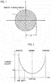
FIG. 1 is a cross-sectional view illustrating an example of an electric wire according to a first embodiment of the present invention; -
FIG. 2 is a graph for explaining a skin depth according to the embodiment of the present invention; -
FIG. 3 is a cross-sectional view for explaining the skin effect of the electric wire; -
FIG. 4 is a graph presenting an example of calculated values of a relation between a frequency and an AC resistance of the electric wire according to the first embodiment of the present invention; -
FIG. 5 is a partially enlarged graph ofFIG. 4 ; -
FIG. 6 is a graph presenting an example of calculated values and measured values of a relation between a frequency and an AC resistance of the electric wire according to the first embodiment of the present invention; -
FIG. 7 is a partially enlarged graph of the measured values inFIG. 6 ; -
FIG. 8 is a cross-sectional view illustrating an example of an electric wire according to a second embodiment of the present invention; -
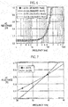
FIG. 9 is a graph presenting an example of calculated values and measured values of a relation between a frequency and an AC resistance of the electric wire according to the second embodiment of the present invention; and -
FIG. 10 is a partially enlarged graph of the measured values inFIG. 9 . - First and second embodiments of the present invention will be described with reference to the accompanying drawings. In the following description of the drawings, same or similar parts are given same or similar reference numerals. However, it is noted that the drawings are schematic and that the relationship between thickness and planar dimensions, the proportion of thicknesses of layers, and the like are different from real ones. Accordingly, specific thicknesses and dimensions should be determined with reference to the following description. It is certain that some portions have different dimensional relations and proportions between the drawings.
- Also, the following embodiments show devices and methods to embody the technical idea of the invention by way of example. The technical ideas of the invention do not limit the materials, shapes, structures, arrangements, and the like of the constituent components to those described below. The technical idea of the invention can be variously changed within the scope of the claims.
- An
electric wire 1 according to a first embodiment of the present invention, as shown inFIG. 1 , is made of a wire material having lower conductivity than copper where a radius a of theelectric wire 1 is smaller than a skin depth thereof, and an AC resistance value of theelectric wire 1 at a frequency used in theelectric wire 1 is provided in excess of a sum of a direct current (DC) resistance value of theelectric wire 1 and a DC resistance value of the copper wire having the same shape and the same outer diameter as theelectric wire 1. - As shown in
FIG.2 , when an AC current is flowing through a conductor, the current density is largest at a conductor surface, and the current density exponentially decreases in a direction from the conductor surface to the conductor center. This is called the skin effect. In this case, the depth of a current density value obtained by multiplying the current density at the conductor surface by "1/e" is defined as "skin depth". "e" is the base of natural logarithm, and 1/e is about 0.37. The higher the frequency of the AC current, the larger the current density at the conductor surface and the less the current density at the conductor center. - The frequency used in the
electric wire 1 according to the first embodiment of the present invention may be set as appropriate according to the specification of each product, and is not particularly limited. For example, it may be about 1 kHz to about 1 MHz, or about 10 kHz to about 100 kHz. In the case of the induction heating (IH) cooking device, it may be about 20 kHz to about 100 kHz. It may be about 50 Hz to about 60 Hz in the case of the product that directly uses the utility frequency in Japan, United State, Europe, China, and the like. - The diameter of the
electric wire 1 according to the first embodiment of the present invention is preferably about 0.05 mm to about 0.6 mm, and is not particularly limited. Copper alloy, such as brass, phosphor bronze, silicon bronze, copper-beryllium alloys, copper-nickel-silicon alloy and the like, maybe used for the wire material constituting theelectric wire 1. Among these, the brass is an alloy (Cu-Zn) containing copper (Cu) and zinc (Zn), and also may contain small amounts of elements other than copper and zinc. The silicon bronze is an alloy (Cu-Sn-Si) containing copper, tin (Sn) and silicon (Si), and also may contain small amounts of elements other than copper, tin and silicon. The phosphorus bronze (Cu-Sn-P) is an alloy containing copper, tin and phosphorus (P), and also may contain small amounts of elements other than copper, tin and phosphorus. These copper alloy wire may be subjected to tin, copper or chromium (Cr) plating. Moreover, theelectric wire 1 may have a cylindrical shape, and also may have a various shape, such as a rectangular shape, and the like. - Furthermore, for the
electric wire 1 according to the first embodiment of the present invention, a copper clad aluminum (CCA) wire in which copper (Cu) is uniformly coated on the outer circumference of an aluminum (Al) wire may be used. Overall diameter of the CCA wire, which is preferably about 0.05 mm to about 0.6 mm, and is not particularly limited. A cross-sectional area of the copper layer is greater than 0 and not more than 30% with respect to the cross-sectional area of the entire electric wire which includes the aluminum wire and the copper layer, preferably about 3% to about 15%, more preferably about 3% to about 10%, further more preferably about 3% to about 5%. As the ratio of the cross-sectional area of the copper layer to the entire electric wire is reduced, the AC resistance can be decreased. For the aluminum wire, for example, aluminum for electric use (EC aluminum) or aluminum alloy, such as Al-Mg-Si alloy (JIS6000 series), may be used. - In the conductor, such as the
electric wire 1 and the like, eddy current may flow in the conductor by the magnetic flux in the conductor, and this eddy current may increase the AC resistance caused by a skin effect. In addition, eddy current may flow in the conductor by an external magnetic flux, and this eddy current may increase the AC resistance caused by a proximity effect. - According to
Patent Document 6, the AC resistance Rac per unit length of the electric wire or coil can be expressed by the following equation (1).
- Here, Rs is a resistance of an element wire per unit length includes the increase due to the skin effect, Rp is a resistance of an element wire per unit length due to the proximity effect. Here, according to
Patent Document 6, Rs and Rp are expressed by the following equation (2) and (3).
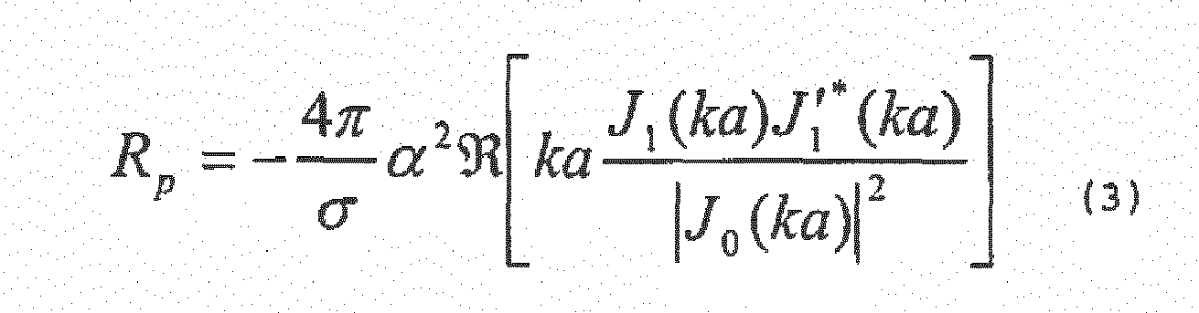

- Here, j is the imaginary unit, π is the circular constant, ω is the angular frequency, µ0 is the permeability of vacuum, a is the radius of the element wire,is the real part of the complex, Jn represents the first kind Bessel function of order n. Moreover, α is a coefficient representing the intensity of the magnetic field acting on the element wire.

- Resistance of the coil or the electric wire is proportional to the length of the conductor forming the coil or the electric wire and inversely proportional to number of the element wires of the conductor constituting the coil or the electric wire. Thus, when the length of the conductor is 1 and a number of the element wires of the conductor is N, the AC resistance of the coil or the electric wire is represented by the following equation (5).

- According to
Patent Document 6, when the intensity of the magnetic field acting on each element wire of the electric wire and the coil is Hi, loss PL of the conductor per unit length due to the eddy current is expressed by the following equation (6).
- Thus, loss of the coil having the number of the element wires N, the number of turns T, and the length li of the conductor of each turn is represented by the following equation (7).

- In addition, T = 1 in case of the electric wire in which the number of turns is one. The energy loss is represented by one-half product of resistance and square of the current, from the expression (5), the loss due to the proximity effect is expressed by the following equation (8).

- Here, i0 is the current in the element wire. From the equations (7) and (8), α is expressed by the following equation (9).

- Here, by assuming a shape of the electric wire or coil, Hi can be obtained by calculation using the finite element method, or calculation using the Ampere law, and the like.
- When the frequency is sufficiently high, the skin effect becomes remarkable, and if the radius a of the
electric wire 1 is greater than the skin depth d as shown inFigure 3 , the current of the element wire flows to concentrate within the skin depth d, as indicated by the shaded area inFigure 3 . On the contrary, in the first embodiment of the present invention, since the radius a of theelectric wire 1 is less than the skin depth, as shown inFIG. 1 , the skin effect may be sufficiently small, and the current in the element wire flows across the entireelectric wire 1. Therefore, the proximity effect is dominant for the AC resistance of theelectric wire 1 or the coil, and Rs may be equal to the DC resistance and is expressed by the following equation (10). Also, according toNon-Patent Document 1, PL is expressed by the following equation (11).

- Thus, the AC resistances Rac1, Rac2 of the coil using two different types of wire materials having conductivity σ1, σ2, respectively, are expressed by the following equations (12), (13), respectively.


- Here, assuming that the values of Rac1, Rac2 are equal, the following equation (14) is obtained.

- The frequency f1 and the AC resistance R1 in this case are expressed by the following equations (15), (16), respectively.


- As mentioned above, when the AC resistances Rac1, Rac2 of the coil using two different types of wire materials having conductivity σ1, σ2, respectively, are equal, the resistance has been found to be equal to the sum of the DC resistances of those coils.
- Consequently, in the
electric wire 1 according to the first embodiment of the present invention and the coil using the same, by using the wire material having lower conductivity than copper, the radius a of theelectric wire 1 is less than the skin depth, and the AC resistance of theelectric wire 1 at the frequency used in theelectric wire 1 or the coil, is provided in excess of a sum of the DC resistance of theelectric wire 1 and the DC resistance of the copper wire having the same shape and the same outer diameter as theelectric wire 1. - That is, when conductivity of the electric wire according to the first embodiment of the present invention is σ1 [Ω-1m-1], conductivity of the copper wire having the same shape and the same outer diameter as the
electric wire 1 is σ2 [Ω-1m-1], coefficient representing an intensity of a magnetic field acting on the electric wire is α [m-1], the circular constant is π, the radii of theelectric wire 1 and the copper wire are a [m], magnetic permeability of vacuum is µ0 [H/m], a number of conductors constituting theelectric wire 1 is N [number], and length of the conductor constituting theelectric wire 1 is 1 [m], the AC resistance R [Ω] of theelectric wire 1 at the frequency used therein is defined to satisfy the following equation (17).
- The frequency f [kHz] of this case satisfies the following equation (18).

- According to the
electric wire 1 and the coil according to the first embodiment of the present invention, the AC resistance can be equal to or less than the copper wire having the same shape and the same outer diameter as the electric wire at the frequency used in theelectric wire 1 and the coil. Furthermore, since it is possible to provide the AC resistance at the frequency used in theelectric wire 1 and the coil by using the DC resistance of the electric wire and the DC resistance of the copper wire having the same shape and the same outer diameter as the electric wire, the electric wire and the coil can be more easily designed. -
FIGs. 4 and 5 show calculated results of the AC resistances of coils using equations (2) to (5) and (9), where each coil is wound 42 turns to the bobbin having an inner diameter of 20.0 mm by twisted nine enameled wires made of copper or aluminum each having an outer diameter of 0.4 mm and a finished diameter of 0.43 mm. - Here, calculation has been done with the conductivity of copper as 5.80×10⁴ Ω-1mm-1 and the conductivity of aluminum as 3.70×10⁴ Ω-1mm-1. In addition, the value of α has been obtained as 5.6 mm-1.
- From
FIGs. 4 and 5 , it can be seen that the DC resistance of the aluminum coil (hereinafter, also referred to as "Al coil") is larger than the copper coil (hereinafter, also referred to as "Cu coil"). Further, it can be seen that the AC resistance of the Al coil is smaller than the AC resistance of the Cu coil in a specific frequency region from the frequency f1 to the frequency f2 which is higher than the frequency f1. - That is, in a frequency lower than the frequency f1, the AC resistance of the Al coil is larger than the AC resistance of the Cu coil. The AC resistances of the Al coil and the Cu coil is consistent with R1 at the frequency f1. Since the proximity effect loss is dominant in the specific frequency range from the frequency f1 to the frequency f2, the magnitude relation of the AC resistances is reversed. The AC resistance of the Al coil and the Cu coil is consistent with R2 at the frequency f2. In a frequency higher than the frequency f2, the AC resistance of the Al coil is greater than the AC resistance of the Cu coil, since its proximity effect is greater than that of copper. In addition, the frequency f1 is shifted more to the lower frequency side as the thicker the element wire diameter or the more the number of turns.
- The frequency f1 shown in
FIG. 4 corresponds to the frequency f1 of the above equation (15). In addition, by setting the radius a of theelectric wire 1 according to the embodiment of the present invention to be smaller than the skin depth, the frequency f defined by the above equation (18) may be lower than the frequency f2 of the high frequency side shown inFIG. 4 . Therefore, because the frequency f is provided higher than the frequency f1 and lower than the frequency f2, it is possible to make the AC resistance equal to or less than the copper wire having the same shape and the same outer diameter as the electric wire. - Then, an Al coil and a Cu coil has been prepared with the same conditions as calculating the AC resistance of the Al coil and the Cu coil shown in
FIGs. 4 and 5 . That is, the Al coil and the Cu coil have been prepared so as to be wound 42 turns to the bobbin having an inner diameter of 20.0 mm by twisted nine enameled wires made of copper or aluminum each having an outer diameter of 0.4 mm and a finished diameter of 0.43 mm. The results of the AC resistances of the prepared Al and Cu coils measured with LCR meter is shown inFIGs. 6 and 7 . InFIG. 6 , the calculated values of the AC resistances of the Cu and Al coils by the equation (5) have been also presented. In this regard, the calculation has been performed with the conductivity of copper as 5.80×10⁴ Q-1mm-1 and the conductivity of aluminum as 3.70×10⁴ Ω-1mm-1. Also, the shape factor α has been determined for both coils as 5.6 mm-1 from the comparison of the calculated value by equation (5) and the measured value. - The DC resistance of the Cu coil is 47.9 mΩ and the DC resistance of the Al coil is 79.4 mΩ, and thus the DC resistance of the Cu coil is lower than the DC resistance of the Al coil. However, as shown in
FIGs. 6 and 7 , each AC resistance increases as the frequency increases, then the AC resistance of the Cu coil and the AC resistance of the Al coil is consistent at the certain frequency, and in the higher frequency side, the AC resistance of the Cu coil is higher than the AC resistance of the Al coil. The frequency when the AC resistance of the Al coil and the AC resistance of the Cu coil are consistent is 39 kHz, and the AC resistance in this case is 131 mΩ. To this measured value, the AC resistance R1 calculated by the sum of the DC resistances by the equation (16) is 127 mΩ, and thus, it has been confirmed to be well consistent with the measured AC resistance. In addition, the frequency f1 calculated by the equation (15) is 38.8 kHz, and thus, it has been confirmed to be well consistent with the measured frequency. - As an example of a design method for the electric wire and the coil according to the first embodiment of the present invention, a wire material having the lower conductivity than copper is selected. Moreover, design will be performed so that the radius of the electric wire is smaller than the skin depth, and the AC resistance of the electric wire at the frequency used in the electric wire or the coil is a sum of the DC resistance of the electric wire and the DC resistance of the copper wire having the same shape and the same outer diameter as the electric wire.
- According to the design method for the electric wire and the coil according to the first embodiment of the present invention, because it is possible to design based on the DC resistance of the electric wire and the DC resistance of the copper wire having the same shape and the same outer diameter as the electric wire, the electric wire and the coil in which the AC resistance can be equal to or less than the AC resistance of the copper wire having the same shape and the same outer diameter as the electric wire can be easily designed and manufactured. In addition, the design method for the electric wire and the coil described above, may be automatically performed by using hardware resources, such as a central processing unit (CPU), a storage device and the like.
- An
electric wire 1 according to a second embodiment of the present invention, as shown inFigure 8 , is a wire material having a double layered structure in which an inner layer (first layer) 2 and an outer layer (second layer) 3 around the periphery of theinner layer 2 are formed, and theinner layer 2 is made of a substance having lower conductivity than copper and theouter layer 3 is made of copper. Then, theelectric wire 1 according to the second embodiment of the present invention has a radius a of theelectric wire 1 which is smaller than the skin depth, and an AC resistance of theelectric wire 1 at a frequency used in theelectric wire 1 is provided in excess of a sum of a value obtained by multiplying a DC resistance value of theelectric wire 1 by a ratio of a cross-sectional area of theinner layer 2 and a cross-sectional area of the entireelectric wire 1, and a DC resistance value of the copper wire having the same shape and the same outer diameter as theelectric wire 1. - The frequency used in the
electric wire 1 according to the second embodiment of the present invention may be set as appropriate according to the specification of each product, and is not particularly limited. For example, it may be about 1 kHz to about 1 MHz, or about 10 kHz to about 100 kHz. In the case of the IH cooking device, it may be about 20 kHz to about 100 kHz. It may be about 50 Hz to about 60 Hz in the case of the product that directly uses the utility frequency in Japan, United State, Europe, China, and the like. - The diameter of the
electric wire 1 according to the second embodiment of the present invention is preferably about 0.05 mm to about 0.6 mm, and is not particularly limited. For theelectric wire 1 according to the second embodiment of the present invention, a copper clad aluminum (CCA) wire in which copper (Cu) as theouter layer 3 is uniformly coated on the outer circumference of an aluminum (Al) wire as theinner layer 2 may be used. A cross-sectional area of the copper layer as theouter layer 3 is greater than 0 and not more than 30% with respect to the cross-sectional area of the entire electric wire which includes the aluminum wire and the copper layer, preferably about 3% to about 15%, more preferably about 3% to about 10%, further more preferably about 3% to about 5%. As the ratio of the cross-sectional area of the copper layer to the entire electric wire is reduced, the AC resistance can be decreased. For the aluminum wire as theinner layer 2, for example, aluminum for electric use (EC aluminum) or aluminum alloy, such as Al-Mg-Si alloy (JIS6000 series), may be used. - For the material of the
inner layer 2, in addition to the aluminum, various materials having low electrical conductivity than copper can be used, but a non-magnetic material is preferable. For example, theelectric wire 1 may be a pipe of copper filling an insulator as theinner layer 2. For the insulator, a resin and air or the like may be used. - In the second embodiment of the present invention, it is also possible to apply the equations (1) to (11) described in the first embodiment of the present invention. In the second embodiment of the present invention, the DC resistance of the electric wire of the double layered structure, where the radius is a, the radius of the
inner layer 2 is b, conductivity of theouter layer 3 is σ2, and conductivity of theinner layer 2 is σ1, can be expressed by the following equation (19). Also, according toNon-Patent Document 2, PL can be expressed by the following equation (20).

- Therefore, the high frequency resistance Rac1 of the coil using the wire material having the double layered structure where the radius is a, the radius of the
inner layer 2 is b, conductivity of theouter layer 3 is σ2, and conductivity of theinner layer 2 is σ1, and the high frequency resistance Rac2 of the coil using the wire material where the radius in a, and conductivity is σ2, can be expressed by the following equations (21) and (22), respectively.

- Here, assuming that the values of Rac1 and Rac2 are equal, the following equation (23) can be obtained.
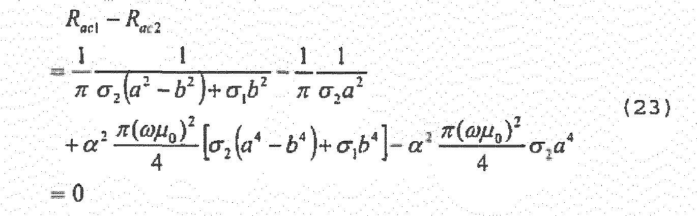
- In this case, the frequency f1 and the high frequency resistance R1 can be expressed by the following equations (24) and (25), respectively.


- Thus, when the high frequency resistances Rac1 and Rac2 of the coils using the two different wire materials that are the wire material having the double layered structure in which the radius is a, the radius of the
inner layer 2 is b, conductivity of theouter layer 3 is σ2 and conductivity of theinner layer 2 is σ1, and the wire material in which the radius is a and conductivity is σ2, respectively, are equal, it has been found that the resistance value is equal to the sum of the value obtained by multiplying a DC resistance value of the wire material of the double layered structure by the ratio of the cross-sectional area of theinner layer 2 and the cross-sectional area of the entire wire material, and the DC resistance value of the copper wire having the same shape and the same outer diameter as the electric wire. - Here, for an example of the electric wire according to the second embodiment of the present invention, the electric wire made of a uniform material may be represented as a case in which the radius b of the
inner layer 2 is equal to the radius a of the entire electric wire. That is, the following equation (26) and (27) may be applied, and those are the same as the equations (15) and (16) for the frequency f1, and the high frequency resistance R1 of theelectric wire 1 in the case of the single layered structure according to the first embodiment of the present invention.

- Thus, when the high frequency resistances Rac1 and Rac2 of the coils using the two different wire materials having the radius a and conductivity σ1, and having the radius a and conductivity σ2 are equal, it has been found that the resistance value R1 is equal to the sum of the DC resistances of these wires.
- Consequently, in the
electric wire 1 and the coil using the same according to the second embodiment of the present invention, the wire material having the double layered structure in which theouter layer 3 is copper and theinner layer 2 has lower conductivity than copper is used, and the radius a of theelectric wire 1 is smaller than the skin depth and the AC resistance of theelectric wire 1 at the frequency used in theelectric wire 1 or the coil is provided in excess of the sum of the value obtained by multiplying the DC resistance value of theelectric wire 1 by the ratio of the cross-sectional area of theinner layer 2 and the cross-sectional area of the entireelectric wire 1, and the DC resistance value of the copper wire having the same shape and the same outer diameter as theelectric wire 1. However, the thickness of theouter layer 3 of theelectric wire 1 may be equal to 0, in which case the ratio of the cross-sectional area of the entireelectric wire 1 and the cross-sectional area of theinner layer 2 is equal to 1. - In other words, when the conductivity of the
inner layer 2 of theelectric wire 1 having the double layered structure is σ1 [Ω-1m-1], the conductivity of the copper is σ2 [Ω-1m-1], the coefficient representing the intensity of the magnetic field acting on theelectric wire 1 is α [m-1], the circular constant is π, the radius of the inner layer is b [m], the radius of theelectric wire 1 is a [m], the magnetic permeability of vacuum is µ0 [H/m], a number of conductors constituting theelectric wire 1 is N [number], and the length of the conductor constituting theelectric wire 1 is 1 [m], the AC resistance R [Ω] of theelectric wire 1 at the frequency used therein is defined so as to satisfy the following equation (28).
- The frequency f [kHz] in this case satisfies the following equation (29).

- According to the
electric wire 1 and the coil according to the second embodiment of the present invention, the AC resistance can be equal to or less than the copper wire having the same shape and the same outer diameter as the electric wire at the frequency used in theelectric wire 1 and the coil. Furthermore, since the AC resistance at the frequency used in theelectric wire 1 and the coil can be provided by using the DC resistance of the electric wire and the DC resistance of the copper wire having the same shape and the same outer diameter as the electric wire, the electric wire and the coil can be more easily designed. - The results of the AC resistances of the coils wound 42 turns to the bobbin having an inner diameter of 20.0 mm by twisted four enameled wires made of copper or CCA each having an outer diameter of 0.6 mm and a finished diameter of 0.63 mm, measured with LCR meter is shown in
FIGs. 9 and 10 . InFIG. 9 , the calculated resistance values of the copper wire coil (hereinafter, also referred to as "Cu coil") and the CCA wire coil (hereinafter, also referred to as "CCA coil") by the above equation (5) are also shown. Here, calculation has been done with the conductivity of copper as 5.80×10⁴ Ω-1mm-1 and the conductivity of aluminum as 3.70×10⁴ Ω-1mm-1. In addition, the shape factor α has been obtained as 2.4 mm-1 by comparison of the calculated value from the equation (5) and the measured value. - The DC resistance of the Cu coil is 47.4 mΩ, the DC resistance of CCA coil is 69.9 mΩ, and thus, the DC resistance of the Cu coil is lower than the DC resistance of the CCA coil. However, as shown in
FIGs. 9 and 10 , each AC resistance increases as the frequency increases, then the AC resistance of the Cu coil and the AC resistance of the CCA coil is consistent at the certain frequency, and in the higher frequency side, the AC resistance of the Cu coil is higher than the AC resistance of the CCA coil. In addition, the frequency at which the AC resistance of the CCA coil and the AC resistance of the Cu coil are consistent is 27.3 kHz, and the AC resistance is 131 mQ. To those measured values, the AC resistance R1 calculated by the sum of the DC resistance by the equation (27) is 130 mΩ, and thus, it has been confirmed to be well consistent with the measured AC resistance. In addition, the frequency f1 calculated by the equation (26) is 28.0 kHz, and thus, it has been confirmed to be well consistent with the measured frequency. - As an example of a design method for the electric wire and the coil according to the second embodiment of the present invention, a wire material having the
outer layer 3 of copper and theinner layer 2 of the substance having lower conductivity than copper is selected. Moreover, design will be performed so that the radius of theelectric wire 1 is smaller than the skin depth, and the AC resistance of theelectric wire 1 at the frequency used in theelectric wire 1 or the coil is the sum of the value obtained by multiplying the DC resistance value of theelectric wire 1 by the ratio of the cross-sectional area of theinner layer 2 and the cross-sectional area of the entireelectric wire 1, and the DC resistance of the copper wire having the same shape and the same outer diameter as theelectric wire 1. - According to the design method for the electric wire and the coil according to the second embodiment of the present invention, because it is possible to design based on the DC resistance of the
electric wire 1, the radius of theouter layer 3 and the radius of theinner layer 2, and the DC resistance of the copper wire having the same shape and the same outer diameter as theelectric wire 1, theelectric wire 1 and the coil in which the AC resistance can be equal to or less than the AC resistance of the copper wire having the same shape and the same outer diameter as theelectric wire 1 can be easily designed and manufactured. In addition, the design method for theelectric wire 1 and the coil described above, may be automatically performed by using hardware resources, such as a central processing unit (CPU), a storage device and the like. - The present invention has been described through the first and second embodiments as mentioned above. However the descriptions and drawings that constitute a portion of this disclosure should not be perceived as limiting this invention. Various alternative embodiments and operational techniques will become clear to persons skilled in the art from this disclosure.
- The electric wire according to the present invention may be applied to an electronics industry including a manufacturing industry of a variety of devices, such as high frequency transformers, motors, reactors, choke coils, induction heating devices, magnetic heads, high frequency power supply cables, DC power supply units, switching power supplies, AC adapters, displacement sensors and flaw detection sensors using eddy current detection, IH cooking heaters, non-contact power feeding devices, high-frequency current generators, and the like.
- In this manner, the present invention naturally includes various embodiments not specifically mentioned herein. Accordingly, the technical scope of the present invention may be limited only by the inventive features set forth by the scope of the patent claims deemed reasonable from the above description.
-
- 1
- electric wire
- 2
- inner layer
- 3
- outer layer
Claims (6)
- An electric wire including a single layered structure having a first layer of a substance having lower conductivity than copper, or including a double layered structure in which a second layer of copper is formed on a periphery of the first layer, wherein
a radius of the electric wire is less than a skin depth,
an alternating current resistance value of the electric wire at a frequency used in the electric wire is provided in excess of a sum of a value obtained by multiplying a direct current resistance value of the electric wire by a ratio of a cross-sectional area of the first layer and a cross-sectional area of the entire electric wire, and a direct current resistance value of a copper wire having a same shape and a same outer diameter as the electric wire. - The electric wire of claim 1, wherein when the electric wire has the single layered structure, the alternating current resistance value of the electric wire at the frequency used in the electric wire is provided in excess of a sum of the direct current resistance value of the electric wire and the direct current resistance value of the copper wire having the same shape and the same outer diameter as the electric wire.
- The electric wire of claim 2, wherein the frequency f used in the electric wire is provided as below

and the alternating current resistance R of the electric wire at the frequency used in the electric wire is provided as below
- The electric wire of claim 1, wherein the electric wire has the double layered structure, the frequency f used in the electric wire is provided as below

and the alternating current resistance R of the electric wire at the frequency used in the electric wire is provided as below
where conductivity of the first layer is σ1, conductivity of the copper wire is σ2, coefficient representing an intensity of a magnetic field acting on the electric wire is α, the circular constant is n, a radius of the first layer is b, a radius of the electric wire is a, magnetic permeability of vacuum is µ0, a number of conductors making up the electric wire is N, and a length of the conductors making up the electric wire is 1. - A coil using the electric wire of any one of claims 1 to 4.
- A method for designing an electric wire, comprising:using a wire material including a single layered structure having a first layer of a substance having lower conductivity than copper, or including a double-layered structure in which a second layer of copper is formed on a periphery of the first layer;designing the electric wire so that a radius of the electric wire is smaller than a skin depth thereof, and an alternating current resistance value of the electric wire at a frequency used in the electric wire is in excess of a sum of a value obtained by multiplying a direct current resistance value of the electric wire by a ratio of a cross-sectional area of the first layer and a cross-sectional area of the entire electric wire, and a direct current resistance value of a copper wire having a same shape and a same outer diameter as the electric wire.
Applications Claiming Priority (2)
| Application Number | Priority Date | Filing Date | Title |
|---|---|---|---|
| JP2013055394 | 2013-03-18 | ||
| PCT/JP2014/057129 WO2014148430A1 (en) | 2013-03-18 | 2014-03-17 | Wire and coil |
Publications (2)
| Publication Number | Publication Date |
|---|---|
| EP2977994A1 true EP2977994A1 (en) | 2016-01-27 |
| EP2977994A4 EP2977994A4 (en) | 2017-01-11 |
Family
ID=51580109
Family Applications (1)
| Application Number | Title | Priority Date | Filing Date |
|---|---|---|---|
| EP14770299.7A Withdrawn EP2977994A4 (en) | 2013-03-18 | 2014-03-17 | Wire and coil |
Country Status (5)
| Country | Link |
|---|---|
| US (1) | US9859032B2 (en) |
| EP (1) | EP2977994A4 (en) |
| JP (1) | JP6062035B2 (en) |
| CN (1) | CN105051833B (en) |
| WO (1) | WO2014148430A1 (en) |
Cited By (3)
| Publication number | Priority date | Publication date | Assignee | Title |
|---|---|---|---|---|
| FR3059142A1 (en) * | 2016-11-18 | 2018-05-25 | Continental Automotive France | ELECTROMAGNETIC ACTUATING DEVICE |
| WO2019007824A1 (en) * | 2017-07-06 | 2019-01-10 | Siemens Aktiengesellschaft | MODULAR MULTI-LEVEL AGREEMENT |
| ES2751695A1 (en) * | 2018-10-01 | 2020-04-01 | Bsh Electrodomesticos Espana Sa | Induction cooking appliance device (Machine-translation by Google Translate, not legally binding) |
Families Citing this family (3)
| Publication number | Priority date | Publication date | Assignee | Title |
|---|---|---|---|---|
| JP2020087735A (en) * | 2018-11-27 | 2020-06-04 | キヤノン電子管デバイス株式会社 | Rotary anode x-ray tube |
| EP3713050B1 (en) * | 2019-03-22 | 2022-05-25 | ABB Schweiz AG | Induction motor |
| WO2025253168A1 (en) * | 2024-06-03 | 2025-12-11 | Ceme S.P.A. | Cca wire coil |
Family Cites Families (14)
| Publication number | Priority date | Publication date | Assignee | Title |
|---|---|---|---|---|
| US3096577A (en) * | 1956-01-12 | 1963-07-09 | Westinghouse Electric Corp | Method of making aluminum clad copper wire |
| FR1428517A (en) * | 1964-11-26 | 1966-02-18 | Selective absorption electrical energy transmission devices | |
| FR2233685B1 (en) * | 1973-06-12 | 1977-05-06 | Josse Bernard | |
| US4256945A (en) * | 1979-08-31 | 1981-03-17 | Iris Associates | Alternating current electrically resistive heating element having intrinsic temperature control |
| JPH0656722B2 (en) | 1985-09-30 | 1994-07-27 | 株式会社フジクラ | High frequency wire |
| US5574260B1 (en) * | 1995-03-06 | 2000-01-18 | Gore & Ass | Composite conductor having improved high frequency signal transmission characteristics |
| JP2002150633A (en) | 2000-11-07 | 2002-05-24 | Matsushita Electric Ind Co Ltd | Magnetic head device |
| JP2005108654A (en) * | 2003-09-30 | 2005-04-21 | Canon Inc | Litz wire, exciting coil and induction heating device using the same |
| WO2006046358A1 (en) | 2004-10-28 | 2006-05-04 | Shinshu University | Apparatus equipped with high frequency coil |
| CN201075311Y (en) * | 2007-09-14 | 2008-06-18 | 曹秉华 | Electric wire cable |
| JP2009129550A (en) | 2007-11-20 | 2009-06-11 | Totoku Electric Co Ltd | Clad wire, litz wire, assembly wire and coil |
| EP2071588A3 (en) * | 2007-12-12 | 2011-11-23 | Alcatel Lucent | Bi-material radio frequency transmission line and the associated manufacturing method |
| BR112013003939A2 (en) * | 2010-08-20 | 2016-07-12 | Fujikura Ltd | electric wire, coil, electrical wire designing apparatus, and electric motor |
| US20120125651A1 (en) * | 2010-11-18 | 2012-05-24 | Timothy Raymond Pearson | Method and apparatus for reduction of skin effect losses in electrical conductors |
-
2014
- 2014-03-17 WO PCT/JP2014/057129 patent/WO2014148430A1/en not_active Ceased
- 2014-03-17 EP EP14770299.7A patent/EP2977994A4/en not_active Withdrawn
- 2014-03-17 CN CN201480016903.7A patent/CN105051833B/en not_active Expired - Fee Related
- 2014-03-17 JP JP2015506766A patent/JP6062035B2/en not_active Expired - Fee Related
- 2014-03-17 US US14/777,964 patent/US9859032B2/en not_active Expired - Fee Related
Cited By (4)
| Publication number | Priority date | Publication date | Assignee | Title |
|---|---|---|---|---|
| FR3059142A1 (en) * | 2016-11-18 | 2018-05-25 | Continental Automotive France | ELECTROMAGNETIC ACTUATING DEVICE |
| WO2019007824A1 (en) * | 2017-07-06 | 2019-01-10 | Siemens Aktiengesellschaft | MODULAR MULTI-LEVEL AGREEMENT |
| ES2751695A1 (en) * | 2018-10-01 | 2020-04-01 | Bsh Electrodomesticos Espana Sa | Induction cooking appliance device (Machine-translation by Google Translate, not legally binding) |
| EP3634088A1 (en) * | 2018-10-01 | 2020-04-08 | BSH Hausgeräte GmbH | Induction cooking device |
Also Published As
| Publication number | Publication date |
|---|---|
| US9859032B2 (en) | 2018-01-02 |
| JPWO2014148430A1 (en) | 2017-02-16 |
| JP6062035B2 (en) | 2017-01-18 |
| CN105051833A (en) | 2015-11-11 |
| CN105051833B (en) | 2017-03-15 |
| WO2014148430A1 (en) | 2014-09-25 |
| EP2977994A4 (en) | 2017-01-11 |
| US20160276051A1 (en) | 2016-09-22 |
Similar Documents
| Publication | Publication Date | Title |
|---|---|---|
| EP2621057B1 (en) | Electric wire, coil, apparatus for designing electric wire, and electric motor | |
| US9859032B2 (en) | Electric wire for reducing AC resistance to be equal to or less than copper wire | |
| Morgan | The current distribution, resistance and internal inductance of linear power system conductors—A review of explicit equations | |
| JP5266340B2 (en) | High frequency electric wire and high frequency coil | |
| Barth et al. | Litz wire design for wireless power transfer in electric vehicles | |
| EP3082135B1 (en) | Electric wire and coil | |
| JP5957428B2 (en) | High frequency electric wire and manufacturing method thereof | |
| JP6194369B2 (en) | High frequency wires and coils | |
| JP2012169288A5 (en) | ||
| Um et al. | Modeling of frequency-dependent winding losses in solid and litz-wire toroidal inductors | |
| Hewitt | Approaches to improving thermal performance of inductors with a view to improving power density |
Legal Events
| Date | Code | Title | Description |
|---|---|---|---|
| PUAI | Public reference made under article 153(3) epc to a published international application that has entered the european phase |
Free format text: ORIGINAL CODE: 0009012 |
|
| 17P | Request for examination filed |
Effective date: 20151016 |
|
| AK | Designated contracting states |
Kind code of ref document: A1 Designated state(s): AL AT BE BG CH CY CZ DE DK EE ES FI FR GB GR HR HU IE IS IT LI LT LU LV MC MK MT NL NO PL PT RO RS SE SI SK SM TR |
|
| AX | Request for extension of the european patent |
Extension state: BA ME |
|
| DAX | Request for extension of the european patent (deleted) | ||
| A4 | Supplementary search report drawn up and despatched |
Effective date: 20161208 |
|
| RIC1 | Information provided on ipc code assigned before grant |
Ipc: H01F 27/28 20060101ALI20161202BHEP Ipc: H01B 7/30 20060101AFI20161202BHEP Ipc: H01B 1/02 20060101ALI20161202BHEP Ipc: H02K 3/02 20060101ALI20161202BHEP Ipc: H01F 5/00 20060101ALI20161202BHEP |
|
| 17Q | First examination report despatched |
Effective date: 20190918 |
|
| STAA | Information on the status of an ep patent application or granted ep patent |
Free format text: STATUS: THE APPLICATION IS DEEMED TO BE WITHDRAWN |
|
| 18D | Application deemed to be withdrawn |
Effective date: 20200129 |