EP2977583B1 - Gas internal combustion engine with pre-chamber fuel supply device - Google Patents
Gas internal combustion engine with pre-chamber fuel supply device Download PDFInfo
- Publication number
- EP2977583B1 EP2977583B1 EP14771002.4A EP14771002A EP2977583B1 EP 2977583 B1 EP2977583 B1 EP 2977583B1 EP 14771002 A EP14771002 A EP 14771002A EP 2977583 B1 EP2977583 B1 EP 2977583B1
- Authority
- EP
- European Patent Office
- Prior art keywords
- chamber
- valve
- gas
- precombustion
- fuel
- Prior art date
- Legal status (The legal status is an assumption and is not a legal conclusion. Google has not performed a legal analysis and makes no representation as to the accuracy of the status listed.)
- Active
Links
- 238000002485 combustion reaction Methods 0.000 title claims description 35
- 239000000446 fuel Substances 0.000 title claims description 28
- 239000007789 gas Substances 0.000 claims description 133
- 239000002737 fuel gas Substances 0.000 claims description 109
- 230000007423 decrease Effects 0.000 claims description 17
- 238000003780 insertion Methods 0.000 claims description 10
- 230000037431 insertion Effects 0.000 claims description 10
- 238000004891 communication Methods 0.000 claims description 6
- 238000003825 pressing Methods 0.000 claims description 5
- 238000007599 discharging Methods 0.000 claims 1
- 230000000149 penetrating effect Effects 0.000 claims 1
- 239000006185 dispersion Substances 0.000 description 11
- 238000001816 cooling Methods 0.000 description 5
- 230000006835 compression Effects 0.000 description 4
- 238000007906 compression Methods 0.000 description 4
- 239000002826 coolant Substances 0.000 description 4
- 239000000567 combustion gas Substances 0.000 description 3
- 239000003570 air Substances 0.000 description 2
- 230000000052 comparative effect Effects 0.000 description 2
- 230000006837 decompression Effects 0.000 description 2
- 230000002093 peripheral effect Effects 0.000 description 2
- 238000011144 upstream manufacturing Methods 0.000 description 2
- 239000012080 ambient air Substances 0.000 description 1
- 230000001174 ascending effect Effects 0.000 description 1
- 230000000694 effects Effects 0.000 description 1
- 239000000284 extract Substances 0.000 description 1
- 238000010348 incorporation Methods 0.000 description 1
- 239000000463 material Substances 0.000 description 1
- 238000000034 method Methods 0.000 description 1
- 238000002156 mixing Methods 0.000 description 1
Images

Classifications
-
- F—MECHANICAL ENGINEERING; LIGHTING; HEATING; WEAPONS; BLASTING
- F02—COMBUSTION ENGINES; HOT-GAS OR COMBUSTION-PRODUCT ENGINE PLANTS
- F02B—INTERNAL-COMBUSTION PISTON ENGINES; COMBUSTION ENGINES IN GENERAL
- F02B19/00—Engines characterised by precombustion chambers
- F02B19/12—Engines characterised by precombustion chambers with positive ignition
-
- F—MECHANICAL ENGINEERING; LIGHTING; HEATING; WEAPONS; BLASTING
- F02—COMBUSTION ENGINES; HOT-GAS OR COMBUSTION-PRODUCT ENGINE PLANTS
- F02B—INTERNAL-COMBUSTION PISTON ENGINES; COMBUSTION ENGINES IN GENERAL
- F02B19/00—Engines characterised by precombustion chambers
- F02B19/10—Engines characterised by precombustion chambers with fuel introduced partly into pre-combustion chamber, and partly into cylinder
- F02B19/1019—Engines characterised by precombustion chambers with fuel introduced partly into pre-combustion chamber, and partly into cylinder with only one pre-combustion chamber
- F02B19/108—Engines characterised by precombustion chambers with fuel introduced partly into pre-combustion chamber, and partly into cylinder with only one pre-combustion chamber with fuel injection at least into pre-combustion chamber, i.e. injector mounted directly in the pre-combustion chamber
- F02B19/1085—Engines characterised by precombustion chambers with fuel introduced partly into pre-combustion chamber, and partly into cylinder with only one pre-combustion chamber with fuel injection at least into pre-combustion chamber, i.e. injector mounted directly in the pre-combustion chamber controlling fuel injection
-
- F—MECHANICAL ENGINEERING; LIGHTING; HEATING; WEAPONS; BLASTING
- F02—COMBUSTION ENGINES; HOT-GAS OR COMBUSTION-PRODUCT ENGINE PLANTS
- F02D—CONTROLLING COMBUSTION ENGINES
- F02D19/00—Controlling engines characterised by their use of non-liquid fuels, pluralities of fuels, or non-fuel substances added to the combustible mixtures
- F02D19/02—Controlling engines characterised by their use of non-liquid fuels, pluralities of fuels, or non-fuel substances added to the combustible mixtures peculiar to engines working with gaseous fuels
- F02D19/021—Control of components of the fuel supply system
- F02D19/023—Control of components of the fuel supply system to adjust the fuel mass or volume flow
- F02D19/024—Control of components of the fuel supply system to adjust the fuel mass or volume flow by controlling fuel injectors
-
- F—MECHANICAL ENGINEERING; LIGHTING; HEATING; WEAPONS; BLASTING
- F02—COMBUSTION ENGINES; HOT-GAS OR COMBUSTION-PRODUCT ENGINE PLANTS
- F02M—SUPPLYING COMBUSTION ENGINES IN GENERAL WITH COMBUSTIBLE MIXTURES OR CONSTITUENTS THEREOF
- F02M21/00—Apparatus for supplying engines with non-liquid fuels, e.g. gaseous fuels stored in liquid form
- F02M21/02—Apparatus for supplying engines with non-liquid fuels, e.g. gaseous fuels stored in liquid form for gaseous fuels
- F02M21/0218—Details on the gaseous fuel supply system, e.g. tanks, valves, pipes, pumps, rails, injectors or mixers
- F02M21/023—Valves; Pressure or flow regulators in the fuel supply or return system
- F02M21/0242—Shut-off valves; Check valves; Safety valves; Pressure relief valves
-
- F—MECHANICAL ENGINEERING; LIGHTING; HEATING; WEAPONS; BLASTING
- F02—COMBUSTION ENGINES; HOT-GAS OR COMBUSTION-PRODUCT ENGINE PLANTS
- F02M—SUPPLYING COMBUSTION ENGINES IN GENERAL WITH COMBUSTIBLE MIXTURES OR CONSTITUENTS THEREOF
- F02M21/00—Apparatus for supplying engines with non-liquid fuels, e.g. gaseous fuels stored in liquid form
- F02M21/02—Apparatus for supplying engines with non-liquid fuels, e.g. gaseous fuels stored in liquid form for gaseous fuels
- F02M21/0218—Details on the gaseous fuel supply system, e.g. tanks, valves, pipes, pumps, rails, injectors or mixers
- F02M21/0248—Injectors
- F02M21/0275—Injectors for in-cylinder direct injection, e.g. injector combined with spark plug
-
- Y—GENERAL TAGGING OF NEW TECHNOLOGICAL DEVELOPMENTS; GENERAL TAGGING OF CROSS-SECTIONAL TECHNOLOGIES SPANNING OVER SEVERAL SECTIONS OF THE IPC; TECHNICAL SUBJECTS COVERED BY FORMER USPC CROSS-REFERENCE ART COLLECTIONS [XRACs] AND DIGESTS
- Y02—TECHNOLOGIES OR APPLICATIONS FOR MITIGATION OR ADAPTATION AGAINST CLIMATE CHANGE
- Y02T—CLIMATE CHANGE MITIGATION TECHNOLOGIES RELATED TO TRANSPORTATION
- Y02T10/00—Road transport of goods or passengers
- Y02T10/10—Internal combustion engine [ICE] based vehicles
- Y02T10/12—Improving ICE efficiencies
-
- Y—GENERAL TAGGING OF NEW TECHNOLOGICAL DEVELOPMENTS; GENERAL TAGGING OF CROSS-SECTIONAL TECHNOLOGIES SPANNING OVER SEVERAL SECTIONS OF THE IPC; TECHNICAL SUBJECTS COVERED BY FORMER USPC CROSS-REFERENCE ART COLLECTIONS [XRACs] AND DIGESTS
- Y02—TECHNOLOGIES OR APPLICATIONS FOR MITIGATION OR ADAPTATION AGAINST CLIMATE CHANGE
- Y02T—CLIMATE CHANGE MITIGATION TECHNOLOGIES RELATED TO TRANSPORTATION
- Y02T10/00—Road transport of goods or passengers
- Y02T10/10—Internal combustion engine [ICE] based vehicles
- Y02T10/30—Use of alternative fuels, e.g. biofuels
Definitions
- the present invention relates to a precombustion-chamber type gas engine including a precombustion chamber to which gas fuel is supplied and a main combustion chamber into which intake-air mixed gas is introduced.
- a precombustion-chamber type lean premixed gas internal combustion engine (hereinafter, referred to in short as a "gas engine”) includes a combustion chamber communicating with the main chamber via a nozzle, which is referred to as a precombustion chamber.
- An intake valve is opened during an intake stroke to introduce lean mixed gas into the main chamber and combustion gas into the precombustion chamber, and mixed gas is produced by mixing the lean mixed gas that flowed into the precombustion chamber from the main chamber via the nozzle during a compression stroke and the fuel gas supplied to the precombustion chamber during the intake stroke.
- the produced mixed gas is combusted by an ignition spark of a spark plug disposed in the precombustion chamber, and a flame is injected into the lean mixed gas in the main combustion chamber from the precombustion chamber via the nozzle.
- This flame is injected into the lean mixed gas in the main combustion chamber to perform main combustion.
- an engine includes a main chamber facing a piston and a precombustion chamber communicating with the main chamber via a nozzle as combustion chambers.
- the engine further includes a precombustion-chamber fuel supply channel for supplying fuel gas to the precombustion chamber and the first check valve which is disposed in the precombustion-chamber fuel supply channel and which opens due to a pressure decrease in the precombustion chamber to allow supply of fuel gas to the precombustion chamber.
- a branch channel is formed on the precombustion-chamber fuel supply channel between the first check valve and the precombustion chamber at an end portion on a downstream side.
- the branch channel includes the second check valve which opens due to a pressure increase in the precombustion chamber to allow gas to flow in from the precombustion-chamber fuel supply channel.
- the first check valve opens while the second check valve is maintained to be closed upon a pressure decrease in the precombustion chamber.
- it is possible to supply fuel gas to the precombustion chamber.
- the second check valve opens while the first check valve is maintained to be closed.
- the fuel gas having been prevailing in the precombustion-chamber fuel supply channel at the downstream side of the first check valve flows into the branch channel.
- the combusted gas in the precombustion chamber flows into the precombustion-chamber fuel supply channel, and the non-combusted gas having been compressed in the precombustion-chamber fuel supply channel flows into the branch channel.
- the precombustion-chamber fuel supply channel between the first check valve and the precombustion chamber is filled with the combusted gas.
- a pressure in the precombustion chamber decreases due to descent of the piston and the second check valve closes, so that the gas in the precombustion-chamber fuel supply channel at the downstream side of the first check valve gradually flows out into the combustion chamber.
- the precombustion-chamber fuel supply channel at the downstream side of the first check valve is filled with the combusted gas, which makes it possible to prevent non-combusted gas from flowing out into the combustion chamber.
- Patent Document 1 discloses reducing the amount of discharge of non-combusted gas in the next exhaust stroke after the expansion stroke to improve engine efficiency.
- Patent Document 1 JP2009-299593A JP 2011/149308 relates to an auxiliary chamber gas supply device which includes the first check valve disposed on an upper part of an auxiliary chamber of a fuel gas inlet passage and allowing flow only to the movement direction of fuel gas, and the second check valve disposed on the upstream side of the first check valve and allowing the flow only to the movement direction of the fuel gas.
- the first check valve which opens due to a pressure decrease in the precombustion chamber to allow fuel gas to be supplied to the precombustion chamber is provided.
- Patent Document 1 describes that the first check valve opens when a pressure decreases to allow fuel gas to be supplied to the precombustion chamber, a check valve is originally designed to be opened or closed by a pressure difference between the upstream side and the downstream side.
- the second check valve opens when the pressure in the combustion chamber increases so that the combustion gas is discharged.
- the present invention was made in view of the above issues to provide a precombustion-chamber fuel supply device for a precombustion-chamber gas engine having high reliability and low operation cost by reducing outflow of fuel gas to the precombustion chamber in the exhaust stroke and dispersion of the amount of fuel gas supplied to the cylinders, which makes it possible to cut fuel consumption and to achieve stable combustion.
- the invention is defined by claim 1.
- the invention relates to a gas internal combustion engine of a Miller-cycle type comprising a precombustion-chamber fuel supply device which includes: a main chamber defined between a piston and a cylinder head of the gas internal combustion engine; a precombustion chamber which communicates with the main chamber via a nozzle and in which fuel gas is combusted by a spark plug; a gas supply channel to precombustion chamber for supplying the fuel gas to the precombustion chamber; and a check valve disposed in the gas supply channel to precombustion chamber and configured to open due to a pressure decrease in the precombustion chamber at a bottom dead center of an intake stroke of a Miller cycle in which the piston closes an intake valve before the bottom dead center of the intake stroke so as to allow supply of the fuel gas to the precombustion chamber.
- the intake valve is closed before the dead bottom center. In this way, a pressure decrease is caused by the further descent of the piston, so that the check valve opens and the fuel gas is supplied to the precombustion chamber.
- the check valve may include a valve body, a valve seat against which the valve body is pressed and which forms a seal portion, and an elastic member which presses the valve body against the seal portion, and a pressing force W of the elastic member may be within a range of a following expression (1): Q 2 ⁇ Sa ⁇ Q 1 ⁇ Sb > W , where Q1 is a gas pressure in the precombustion chamber at the bottom dead center in the intake stroke; Q2 is a fuel-gas pressure of the gas supply channel to precombustion chamber; Sa is a fuel-gas pressure receiving area of the valve body; and Sb is a precombustion-chamber gas pressure receiving area of the valve body.
- the pressing force W of the elastic member is smaller than a difference between a product of Q2, the fuel-gas pressure of the gas supply channel to precombustion chamber, and Sa, the fuel-gas pressure receiving area of the valve body on a side closer to the precombustion-chamber supply channel, and a product of Ql, the gas pressure in the precombustion chamber at the bottom dead center in the intake stroke, and Sb, the precombustion-chamber gas pressure receiving area of the valve body.
- the check valve is opened by the pressure decrease in the precombustion chamber at the bottom dead center in the intake stroke of the Miller cycle, which makes it possible to reduce the supply pressure of the fuel gas.
- the fuel gas pressure of the gas supply channel to precombustion chamber may be set to be lower than the gas pressure in the precombustion chamber in an exhaust stroke.
- the fuel gas pressure of the gas supply channel to precombustion chamber is set to be lower than the gas pressure in the precombustion chamber in an exhaust stroke, and is applied in a direction in which the check-valve is closed in the exhaust stroke.
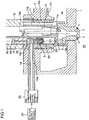
- FIG. 1 is a schematic cross-sectional view of a precombustion chamber and its peripheral structure of a gas engine according to one embodiment of the present invention.
- a main chamber 60 being a main combustion chamber is defined between a piston (not illustrated) and a cylinder head 1. Further, a precombustion-chamber cap 2 is fixed to an upper part of the cylinder head 1, surrounded by a coolant water channel 1a. A precombustion chamber 4 is formed inside the precombustion-chamber cap 2 ("4a" indicates the center of the precombustion chamber 4). The precombustion chamber 4 communicates with the main chamber 60 via nozzles 3.
- the precombustion-chamber cap 2 is pressed by an ignition-plug holder 13 and a retainer 12 at a precombustion-chamber upper surface at the upper part of the precombustion-chamber cap 2, so as to be fixed to the cylinder head 1.
- a spark plug 10 is fixed inside the ignition-plug holder 13 via an attachment seat surface.
- a bore-cooling coolant hole 11s and a check-valve insertion hole 6s are formed in the ignition-plug holder 13 around the precombustion chamber 4.
- the bore-cooling coolant hole 11s is configured such that a lower bore-cooling side hole 11a (inlet hole) communicates to an upper bore-cooling side hole 11b (outlet hole) via a plurality of bore-cooling vertical holes (vertical coolant holes) 11 that is parallel to an axial center line 10a of the spark plug 10, so as to surround a high-temperature section of the spark plug 10.
- the check-valve insertion hole 6s is disposed so that the center 6a of the check-valve insertion hole 6s is parallel to the center line 10a of the spark plug 10, and a check valve 6 supported by a check-valve holder 9 is disposed at the lower part of the check-valve insertion hole 6s.
- the inside of the check-valve insertion hole 6s is divided into two spaces: a check-valve upper chamber 28 and a check-valve lower chamber 29.
- the check-valve lower chamber 29 and the precombustion chamber 4 are in communication through a gas supply hole to precombustion chamber 5.
- a fuel-inlet connector 14a is connected to a side of the ignition-plug holder 13, so that a gas supply channel to precombustion chamber 14 formed inside the fuel-inlet connector 14a communicates with the ignition-plug holder 13.
- the fuel-inlet connector 14a is formed as a separate member from the ignition-plug holder 13, and screwed to the ignition-plug holder 13 to be fixed to the fuel-gas inlet part 14s.
- the other end of the fuel-inlet connector 14a is connected to a fuel-gas supply source 24 via a precombustion-chamber electromagnetic valve 23.
- the fuel-gas supply source 24 is configured to discharge the fuel gas to the gas supply channel to precombustion chamber 4 at a substantially constant pressure.
- the discharge pressure is an atmospheric pressure.
- the precombustion-chamber electromagnetic valve 23 is configured such that a valve body normally biased toward a valve-closed direction by a spring or the like resists the spring force to operate toward a valve-open direction when a solenoid part is excited by supply of power. Further, the precombustion-chamber electromagnetic valve 23 is configured such that the valve body operates toward the valve-closed direction with the spring force when the power supply is stopped. Input of an opening/closing signal to the precombustion-chamber electromagnetic valve 23, i.e., on/off of power supply is controlled on the basis of a signal of a crank-angle sensor (not illustrated).
- the precombustion-chamber gas supply device for a gas engine of the present embodiment having the above configuration, when a valve-opening signal is inputted to the precombustion-chamber electromagnetic valve 23 connected to the fuel-gas supply source 24, the solenoid part is excited and the valve body moves to be open, so that the fuel gas flows out to the combustion-chamber gas supply channel 14 from the fuel-gas supply source 24.
- the fuel gas having flowed out flows into the check-valve upper chamber 28 via a fuel-gas inlet part 14s, and then to the precombustion chamber 4 from the check-valve lower chamber 28 via the gas supply hole to precombustion chamber 5.
- the gas supply channel to precombustion chamber for supplying fuel gas to the precombustion chamber 4 is constituted by the above precombustion-gas supply channel 14, the check-valve upper chamber 28, the check-valve lower chamber 29, and the gas supply hole to precombustion chamber 5.
- the precombustion-chamber electromagnetic valve 23 is disposed between the fuel-gas supply source 24 and the check-valve upper chamber 28. In this way, the precombustion-chamber electromagnetic valve 23 functions as a safety valve when fuel gas leaks at the check valve 6 or the like during shutdown or the like of the gas engine.
- the precombustion-chamber electromagnetic valve 23 has a pressure-adjustment function, which makes it possible to stabilize the gas discharge pressure (atmospheric pressure) to the check-valve upper chamber 28, and to reduce dispersion of the amount of fuel gas supply to the precombustion chamber 4 as the fuel gas passes through the precombustion-chamber electromagnetic valve 23.
- FIG. 2 is an old-and-new comparison chart of fuel-gas supply pressure of a gas engine according to one embodiment of the present invention.
- the vertical axis is the in-cylinder pressure of the gas engine, which is the capacity for supplying fuel gas to the precombustion chamber.
- the horizontal axis is the stroke of the piston accompanying the rotation of the gas engine.
- the in-cylinder pressure is a pressure including the main chamber 60 and the precombustion chamber 4 which communicates with the main chamber 60 via the nozzles 3.
- the in-cylinder pressure is increased by compression of lean mixed gas introduced into the main chamber 60 from an intake device, in accordance with the progress in the compression stroke of the piston.
- TDC top dead center
- Q7 in-cylinder pressure Q7
- TDC top dead center
- the thick fuel gas in the precombustion chamber 4 and the lean fuel gas flowing into the precombustion chamber 4 from the main chamber 60 via the nozzles 3 are mixed and combusted by the spark plug 10 of the precombustion chamber.
- the combusted flame blows out into the main chamber 60 via the nozzles 3, and the process advances to a combustion stroke in which the lean fuel gas in the main chamber 60 is combusted (exploded).
- the pressure in the combustion chamber increases rapidly, so as to reach the maximum in-cylinder pressure Q8 when the piston has passed the TDC.
- the piston starts to descend while receiving a combustion pressure, so as to be outputted as a rotation output by the rotation of the crank shaft (not illustrated).
- the piston continues descending to reach a bottom dead center (hereinafter, referred to as BDC), and then the piston enters an ascending stroke again, i.e., an exhaust stroke of exhaust gas produced by combustion of the lean mixed gas.
- BDC bottom dead center
- the in-cylinder pressure is Q3 during the exhaust stroke of the piston increases to Q5 in the intake stroke due to incorporation of the lean mixed gas (dotted line in FIG. 2 ). Subsequently, the piston enters the compression stroke and the in-cylinder pressure increases.
- a required amount of fuel gas may not enter the precombustion chamber 4 if the supply pressure Q6 of the fuel gas is not maintained to be higher than the pressure of the lean mixed gas flowing into the main chamber 60.
- a differential pressure ⁇ Q is set between the fuel-gas supply pressure Q6 supplied to the precombustion chamber 4 and the in-cylinder pressure Q5 in the intake stroke, so that it is possible to supply fuel gas to the precombustion chamber 4.
- the fuel-gas supply pressure Q6 is higher than the in-cylinder pressure Q3 in the exhaust stroke.
- the fuel gas flows into the precombustion chamber 4 to be discharged from the gas engine to the outside as non-combusted gas, thereby producing wasted fuel.
- the in-cylinder pressure Q3 in the exhaust stroke of the piston increases to the in-cylinder pressure Q5 when the piston enters the intake stroke.
- a Miller-cycle type gas engine has a structure in which the piston descends in the intake stroke and an intake valve for introducing lean mixed gas is closed at D1 (e.g. approximately 40 degrees in crank angle) before BDC.
- the amount of decompression in the in-cylinder pressure Q5-Q4 (M1) is small because the amount of movement of the piston toward the BDC is small. Further, the fuel-gas supply pressure Q6 is higher than the in-cylinder pressure Q3 in the exhaust stroke.
- the fuel gas is supplied to the precombustion chamber 4 with a differential pressure of ⁇ Q, and thus a large amount of fuel gas is likely to be supplied to the precombustion chamber at the moment when the check valve opens.
- a large amount of fuel gas is likely to be supplied to the precombustion chamber at the moment when the check valve opens.
- dispersion is likely to occur in the amount of fuel gas supply to each cylinder.
- the fuel supply pressure Q6 is higher than the in-cylinder pressure Q3 in the exhaust stroke.
- the fuel gas flows to the precombustion chamber 4 to be discharged as non-combusted gas to the outside from the gas engine, thereby producing wasted fuel.
- the Miller-cycle type gas engine according to the present invention has a structure in which the piston descends in the intake stroke and an intake valve for introducing lean mixed gas is closed at D2 at 60 to 120 degrees crank angle before BDC
- the in-cylinder pressure Q1 decreases in the intake stroke (solid line in FIG. 2 ).
- the in-cylinder pressure decreases considerably (M2) downward (decompression direction) as indicated by the solid line from the middle of the intake stroke.
- the precombustion chamber communicating with the main chamber reaches the same pressure as the in-cylinder pressure.
- the time of closing the intake valve is further advanced from the BDC, which reduces the lean mixed gas introduced into the cylinder. Further, the period (amount of stroke) from the point of time when the intake valve is closed to the BDC is increased, which causes the in-cylinder pressure to become a negative pressure.
- the time of closing the intake valve is advanced before the BDC to reduce the pressure of the lean mixed gas in the main chamber 60 and the precombustion chamber 4.
- the time of closing the intake valve is set so that the pressure Q1 of the lean mixed gas of the main chamber 60 and the precombustion chamber 4 becomes a pressure lower than the fuel gas supply pressure Q2 in the gas supply channel to precombustion chamber 14.
- the fuel gas supply pressure Q2 in the gas supply channel to precombustion chamber 14 is not pressurized but used as a substantially atmospheric pressure.
- the in-cylinder pressure is higher than the atmospheric pressure in the exhaust stroke.
- the fuel gas supply pressure Q2 in the gas supply channel to precombustion chamber 14 is lower than the in-cylinder pressure Q3 in the exhaust stroke.
- the check valve opens and the fuel gas in the gas supply channel to precombustion chamber 14 is sucked into the precombustion chamber 4.
- the differential pressure between the check-valve upper chamber 28 and the precombustion chamber 4 is caused by the amount of movement of the piston after closure of the intake valve.
- dispersion in the generated differential pressure is small, which in accordance decreases dispersion of the amount of fuel gas supply to the precombustion chamber 4.
- rotation of the gas engine becomes stable.
- the check valve 6 receives a pressure in the closing direction because, in the exhaust stroke, the fuel supply pressure Q2 is lower than the in-cylinder pressure Q3 in the exhaust stroke.
- the fuel gas does not flow to the precombustion chamber 4, which makes it possible to prevent leakage of the fuel gas in the exhaust stroke.
- the check valve 6 opens due to a pressure decrease caused by closure of the intake valve by the piston at D2 before the BDC in the intake stroke so as to allow supply of the fuel gas to the precombustion chamber.
- the check valve 6 is configured to be securely operated by a differential pressure between the lean mixed gas pressure Q1 of the precombustion chamber 4 and the fuel gas supply pressure Q2 (the check-valve upper chamber 28) in the gas supply channel to precombustion chamber 14.
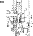
- the check valve 6 will be described with reference to FIG. 3 .
- the check valve 6 includes a check-valve body 61, a valve body 62 mounted to a center shaft portion of the check-valve body 61 through the check-valve body 61, and a coil spring 63 which is an elastic member that presses the valve body 62 against a seal portion 61c disposed on the check-valve body 61 so as to face the check-valve lower chamber 29.
- the check-valve body 61 includes a through hole 61b, a plurality of communication channels 61a, and a seal portion 61c.
- the through hole 61b penetrates through the center of the check-valve body 61 from the check-valve upper chamber 28 to the check-valve lower chamber 29 along the axis of the check-valve body 61.
- the plurality of communication channels 61a communicate with the through hole 61b in the vicinity of a side of the through hole 61b adjacent to the check-valve lower chamber 29 and have openings adjacent to the check-valve upper chamber 28.
- the plurality of communication channels 61a is disposed outside of the outer periphery of the through hole 61b.
- the valve body 62 includes a column portion 62c fitted into the through hole 61b, a valve-body top portion 62a that has a shape of an umbrella, and a stopper portion 62b.
- the valve-body top portion 62a is formed on the column portion 62c adjacently to the check-valve lower chamber 29 and is in contact with the seal portion 61c so as to prevent fuel gas from flowing from the check-valve upper chamber 28 toward the check-valve lower chamber 29.
- the stopper portion 62b is formed on the column portion 62c adjacently to the check-valve upper chamber 28 so as to retain the coil spring 63 fitted onto the outer circumferential part of the column portion 62c in a compressed state between the check-valve body 61 and the stopper portion 62b.
- Valve-opening operation of the check-valve 6 is adjusted as follows.
- the spring pressing force W satisfies: Q 2 ⁇ Sa ⁇ Q 1 ⁇ Sb > W , where Q1 is a gas pressure in the precombustion chamber 4 at the bottom dead center in the intake stroke; Q2 is a fuel-gas pressure of the gas supply channel to precombustion chamber 14; Sa is a fuel-gas pressure receiving area of the valve body 62; and Sb is a precombustion-chamber gas pressure receiving area of the valve body 62.
- the pressing force W of the coil spring 63 is set to be lower than a difference of; a product of the fuel gas pressure Q2 of the gas supply channel to precombustion chamber 14 and the fuel-gas pressure receiving area Sa of the stopper portion 62b; and a product of the gas pressure Q1 in the precombustion chamber 4 at the BDC in the intake stroke and the gas pressure receiving area Sb of the valve-body top portion 62a of the valve body 62. In this way, the valve-opening pressure of the check valve 6 is reduced so that fuel gas is not supplied to the precombustion chamber 4 unnecessarily.
- the gas pressure P2 in the precombustion chamber 4 at the bottom dead center in the intake stroke is a pressure decrease caused by closure of the intake valve at D2 before the BDC and the amount of movement of the piston.
- the pressure becomes constant and dispersion of the amount of fuel gas supply (introduction amount) from the gas supply channel to precombustion chamber 14 to the precombustion chamber 4 is reduced, which makes it possible to achieve stable combustion of the gas engine.
- a precombustion-chamber fuel supply device for a gas engine that supplies fuel gas to a precombustion chamber of a precombustion-chamber type lean premixed gas engine in which a spark plug is used for ignition.
Description
- The present invention relates to a precombustion-chamber type gas engine including a precombustion chamber to which gas fuel is supplied and a main combustion chamber into which intake-air mixed gas is introduced.
- In addition to a normal combustion chamber called a main chamber, a precombustion-chamber type lean premixed gas internal combustion engine (hereinafter, referred to in short as a "gas engine") includes a combustion chamber communicating with the main chamber via a nozzle, which is referred to as a precombustion chamber.
- An intake valve is opened during an intake stroke to introduce lean mixed gas into the main chamber and combustion gas into the precombustion chamber, and mixed gas is produced by mixing the lean mixed gas that flowed into the precombustion chamber from the main chamber via the nozzle during a compression stroke and the fuel gas supplied to the precombustion chamber during the intake stroke.
- The produced mixed gas is combusted by an ignition spark of a spark plug disposed in the precombustion chamber, and a flame is injected into the lean mixed gas in the main combustion chamber from the precombustion chamber via the nozzle.
- This flame is injected into the lean mixed gas in the main combustion chamber to perform main combustion.
- According to
Patent Document 1, an engine includes a main chamber facing a piston and a precombustion chamber communicating with the main chamber via a nozzle as combustion chambers. The engine further includes a precombustion-chamber fuel supply channel for supplying fuel gas to the precombustion chamber and the first check valve which is disposed in the precombustion-chamber fuel supply channel and which opens due to a pressure decrease in the precombustion chamber to allow supply of fuel gas to the precombustion chamber. - A branch channel is formed on the precombustion-chamber fuel supply channel between the first check valve and the precombustion chamber at an end portion on a downstream side. The branch channel includes the second check valve which opens due to a pressure increase in the precombustion chamber to allow gas to flow in from the precombustion-chamber fuel supply channel.
- With the above structure, the first check valve opens while the second check valve is maintained to be closed upon a pressure decrease in the precombustion chamber. Thus, it is possible to supply fuel gas to the precombustion chamber.
- When a pressure in the precombustion chamber increases, the second check valve opens while the first check valve is maintained to be closed. Thus, the fuel gas having been prevailing in the precombustion-chamber fuel supply channel at the downstream side of the first check valve flows into the branch channel.
- In this way, when ignition takes place in the precombustion chamber and the mixed air is combusted, the pressure in the precombustion chamber increases and the second check valve opens.
- As a result, the combusted gas in the precombustion chamber flows into the precombustion-chamber fuel supply channel, and the non-combusted gas having been compressed in the precombustion-chamber fuel supply channel flows into the branch channel. Thus, the precombustion-chamber fuel supply channel between the first check valve and the precombustion chamber is filled with the combusted gas. In an expansion stroke, a pressure in the precombustion chamber decreases due to descent of the piston and the second check valve closes, so that the gas in the precombustion-chamber fuel supply channel at the downstream side of the first check valve gradually flows out into the combustion chamber. Here, the precombustion-chamber fuel supply channel at the downstream side of the first check valve is filled with the combusted gas, which makes it possible to prevent non-combusted gas from flowing out into the combustion chamber.
- Accordingly,
Patent Document 1 discloses reducing the amount of discharge of non-combusted gas in the next exhaust stroke after the expansion stroke to improve engine efficiency. - Patent Document 1:
JP2009-299593A
JP 2011/149308 claim 1.EP 2 372 135 A1JP 2009/221935 A JP 2007/270782 A - However, according to
Patent Document 1, the first check valve which opens due to a pressure decrease in the precombustion chamber to allow fuel gas to be supplied to the precombustion chamber is provided. - While
Patent Document 1 describes that the first check valve opens when a pressure decreases to allow fuel gas to be supplied to the precombustion chamber, a check valve is originally designed to be opened or closed by a pressure difference between the upstream side and the downstream side. - Accordingly, in
Patent Document 1, the in-cylinder pressure becomes the lowest in the intake stroke and the exhaust stroke. - Thus, there is a problem that a differential pressure between the inside of the precombustion-chamber fuel supply channel and the inside of the precombustion chamber is generated in the first check valve and fuel gas is supplied to the precombustion chamber also in the exhaust stroke, thereby wasting the fuel gas.
- Further, in the combustion stroke, the second check valve opens when the pressure in the combustion chamber increases so that the combustion gas is discharged. Thus, there is a problem that the output of the gas engine decreases, because the gas engine extracts power from a pressure of the combustion gas.
- The present invention was made in view of the above issues to provide a precombustion-chamber fuel supply device for a precombustion-chamber gas engine having high reliability and low operation cost by reducing outflow of fuel gas to the precombustion chamber in the exhaust stroke and dispersion of the amount of fuel gas supplied to the cylinders, which makes it possible to cut fuel consumption and to achieve stable combustion.
- The invention is defined by
claim 1. - The invention relates to a gas internal combustion engine of a Miller-cycle type comprising a precombustion-chamber fuel supply device which includes: a main chamber defined between a piston and a cylinder head of the gas internal combustion engine; a precombustion chamber which communicates with the main chamber via a nozzle and in which fuel gas is combusted by a spark plug; a gas supply channel to precombustion chamber for supplying the fuel gas to the precombustion chamber; and a check valve disposed in the gas supply channel to precombustion chamber and configured to open due to a pressure decrease in the precombustion chamber at a bottom dead center of an intake stroke of a Miller cycle in which the piston closes an intake valve before the bottom dead center of the intake stroke so as to allow supply of the fuel gas to the precombustion chamber.
- According to the above invention, during an intake stroke of the piston, the intake valve is closed before the dead bottom center. In this way, a pressure decrease is caused by the further descent of the piston, so that the check valve opens and the fuel gas is supplied to the precombustion chamber.
- Further, since the pressure decrease is caused by closure of the valve and the amount of movement of the piston, the pressure becomes constant and dispersion of the amount of fuel gas supply to the precombustion chamber is reduced, which makes it possible to achieve stable combustion of the gas engine.
- Specifically, if the fuel gas is supplied to the precombustion chamber while being pressurized, a large amount of fuel gas is likely to be supplied to the precombustion chamber at the moment when the check-valve opens. As a result, due to multiple causes including supply-pressure fluctuation of a supply pump and a difference in flow resistance of fuel gas caused by the distance from the supply pump to each cylinder or the like, dispersion is likely to occur in the amount of fuel gas supply to each cylinder. The present invention makes the above event unlikely to occur.
- Further, preferably in the present invention, the check valve may include a valve body, a valve seat against which the valve body is pressed and which forms a seal portion, and an elastic member which presses the valve body against the seal portion, and
a pressing force W of the elastic member may be within a range of a following expression (1):
- According to the above invention, the pressing force W of the elastic member is smaller than a difference between a product of Q2, the fuel-gas pressure of the gas supply channel to precombustion chamber, and Sa, the fuel-gas pressure receiving area of the valve body on a side closer to the precombustion-chamber supply channel, and a product of Ql, the gas pressure in the precombustion chamber at the bottom dead center in the intake stroke, and Sb, the precombustion-chamber gas pressure receiving area of the valve body.
- In this way, the check valve is opened by the pressure decrease in the precombustion chamber at the bottom dead center in the intake stroke of the Miller cycle, which makes it possible to reduce the supply pressure of the fuel gas.
- Thus, it is possible to reduce the supply pressure of the fuel gas, which reduces dispersion of the amount of fuel-gas supply to each cylinder and enables stable combustion of the gas engine.
- Further, preferably in the present invention, the fuel gas pressure of the gas supply channel to precombustion chamber may be set to be lower than the gas pressure in the precombustion chamber in an exhaust stroke.
- According to the above invention, the fuel gas pressure of the gas supply channel to precombustion chamber is set to be lower than the gas pressure in the precombustion chamber in an exhaust stroke, and is applied in a direction in which the check-valve is closed in the exhaust stroke. Thus, it is possible to restrict the fuel gas from flowing into the precombustion chamber during the exhaust stroke and to prevent outflow of the fuel gas in the exhaust stroke.
- With the above configuration, it is possible to reduce outflow of fuel gas to the precombustion chamber in the exhaust stroke and dispersion of the amount of fuel gas supply to the cylinders, which makes it possible to cut fuel consumption and achieve stable combustion. As a result, it is possible to provide a precombustion-chamber fuel supply device for a precombustion-chamber gas engine having high reliability and low operation cost.
-
-
FIG. 1 is a schematic cross-sectional view of a precombustion chamber and its peripheral structure of a gas engine according to one embodiment of the present invention. -
FIG. 2 is a comparison chart of fuel-gas supply pressure of a gas engine according to one embodiment of the present invention. -
FIG. 3 is an enlarged view of a check valve of a gas engine according to one embodiment of the present invention. - Embodiments of the present invention will now be described in detail with reference to the accompanying drawings.
- It is intended, however, that unless particularly specified, dimensions, materials, shapes, relative positions and the like of components described in the embodiments shall be interpreted as illustrative only and not limitative of the scope of the present invention.
-
FIG. 1 is a schematic cross-sectional view of a precombustion chamber and its peripheral structure of a gas engine according to one embodiment of the present invention. - In
FIG. 1 , amain chamber 60 being a main combustion chamber is defined between a piston (not illustrated) and acylinder head 1. Further, a precombustion-chamber cap 2 is fixed to an upper part of thecylinder head 1, surrounded by acoolant water channel 1a. Aprecombustion chamber 4 is formed inside the precombustion-chamber cap 2 ("4a" indicates the center of the precombustion chamber 4). Theprecombustion chamber 4 communicates with themain chamber 60 vianozzles 3. - Further, the precombustion-
chamber cap 2 is pressed by an ignition-plug holder 13 and aretainer 12 at a precombustion-chamber upper surface at the upper part of the precombustion-chamber cap 2, so as to be fixed to thecylinder head 1. Aspark plug 10 is fixed inside the ignition-plug holder 13 via an attachment seat surface. - Further, as illustrated in
FIG. 1 , a bore-coolingcoolant hole 11s and a check-valve insertion hole 6s are formed in the ignition-plug holder 13 around theprecombustion chamber 4. The bore-coolingcoolant hole 11s is configured such that a lower bore-coolingside hole 11a (inlet hole) communicates to an upper bore-coolingside hole 11b (outlet hole) via a plurality of bore-cooling vertical holes (vertical coolant holes) 11 that is parallel to anaxial center line 10a of thespark plug 10, so as to surround a high-temperature section of thespark plug 10. - Further, the check-
valve insertion hole 6s is disposed so that thecenter 6a of the check-valve insertion hole 6s is parallel to thecenter line 10a of thespark plug 10, and acheck valve 6 supported by a check-valve holder 9 is disposed at the lower part of the check-valve insertion hole 6s. With thecheck valve 6 being provided, the inside of the check-valve insertion hole 6s is divided into two spaces: a check-valveupper chamber 28 and a check-valvelower chamber 29. The check-valvelower chamber 29 and theprecombustion chamber 4 are in communication through a gas supply hole toprecombustion chamber 5. - Further, an end of a fuel-
inlet connector 14a is connected to a side of the ignition-plug holder 13, so that a gas supply channel toprecombustion chamber 14 formed inside the fuel-inlet connector 14a communicates with the ignition-plug holder 13. The fuel-inlet connector 14a is formed as a separate member from the ignition-plug holder 13, and screwed to the ignition-plug holder 13 to be fixed to the fuel-gas inlet part 14s. - Further, the other end of the fuel-
inlet connector 14a is connected to a fuel-gas supply source 24 via a precombustion-chamberelectromagnetic valve 23. The fuel-gas supply source 24 is configured to discharge the fuel gas to the gas supply channel toprecombustion chamber 4 at a substantially constant pressure. The discharge pressure is an atmospheric pressure. - The precombustion-chamber
electromagnetic valve 23 is configured such that a valve body normally biased toward a valve-closed direction by a spring or the like resists the spring force to operate toward a valve-open direction when a solenoid part is excited by supply of power. Further, the precombustion-chamberelectromagnetic valve 23 is configured such that the valve body operates toward the valve-closed direction with the spring force when the power supply is stopped. Input of an opening/closing signal to the precombustion-chamberelectromagnetic valve 23, i.e., on/off of power supply is controlled on the basis of a signal of a crank-angle sensor (not illustrated). - In the precombustion-chamber gas supply device for a gas engine of the present embodiment having the above configuration, when a valve-opening signal is inputted to the precombustion-chamber
electromagnetic valve 23 connected to the fuel-gas supply source 24, the solenoid part is excited and the valve body moves to be open, so that the fuel gas flows out to the combustion-chambergas supply channel 14 from the fuel-gas supply source 24. The fuel gas having flowed out flows into the check-valveupper chamber 28 via a fuel-gas inlet part 14s, and then to theprecombustion chamber 4 from the check-valvelower chamber 28 via the gas supply hole toprecombustion chamber 5. That is, the gas supply channel to precombustion chamber for supplying fuel gas to theprecombustion chamber 4 is constituted by the above precombustion-gas supply channel 14, the check-valveupper chamber 28, the check-valvelower chamber 29, and the gas supply hole toprecombustion chamber 5. - The precombustion-chamber
electromagnetic valve 23 is disposed between the fuel-gas supply source 24 and the check-valveupper chamber 28. In this way, the precombustion-chamberelectromagnetic valve 23 functions as a safety valve when fuel gas leaks at thecheck valve 6 or the like during shutdown or the like of the gas engine. - Further, the precombustion-chamber
electromagnetic valve 23 has a pressure-adjustment function, which makes it possible to stabilize the gas discharge pressure (atmospheric pressure) to the check-valveupper chamber 28, and to reduce dispersion of the amount of fuel gas supply to theprecombustion chamber 4 as the fuel gas passes through the precombustion-chamberelectromagnetic valve 23. -
FIG. 2 is an old-and-new comparison chart of fuel-gas supply pressure of a gas engine according to one embodiment of the present invention. - The vertical axis is the in-cylinder pressure of the gas engine, which is the capacity for supplying fuel gas to the precombustion chamber. The horizontal axis is the stroke of the piston accompanying the rotation of the gas engine.
- Here, the in-cylinder pressure is a pressure including the
main chamber 60 and theprecombustion chamber 4 which communicates with themain chamber 60 via thenozzles 3. - The in-cylinder pressure is increased by compression of lean mixed gas introduced into the
main chamber 60 from an intake device, in accordance with the progress in the compression stroke of the piston. - When the piston reaches the vicinity of the top dead center (hereinafter, referred to as TDC) (in-cylinder pressure Q7), the thick fuel gas in the
precombustion chamber 4 and the lean fuel gas flowing into theprecombustion chamber 4 from themain chamber 60 via thenozzles 3 are mixed and combusted by thespark plug 10 of the precombustion chamber. The combusted flame blows out into themain chamber 60 via thenozzles 3, and the process advances to a combustion stroke in which the lean fuel gas in themain chamber 60 is combusted (exploded). - In accordance with the combustion, the pressure in the combustion chamber increases rapidly, so as to reach the maximum in-cylinder pressure Q8 when the piston has passed the TDC. The piston starts to descend while receiving a combustion pressure, so as to be outputted as a rotation output by the rotation of the crank shaft (not illustrated).
- The piston continues descending to reach a bottom dead center (hereinafter, referred to as BDC), and then the piston enters an ascending stroke again, i.e., an exhaust stroke of exhaust gas produced by combustion of the lean mixed gas.
- When the exhaust gas is emitted into the ambient air via an exhaust channel, flow resistance of exhaust gas is caused in the exhaust channel or the like. Thus, even though the exhaust gas is emitted while the piston ascends, the in-cylinder pressure (exhaust gas) is maintained to have a pressure Q3 which is higher than the atmospheric pressure.
- When the piston comes to the TDC passing position again, the exhaust valve closes. On the other hand, the intake valve opens before the piston passes the TDC, and then the piston starts to descend again to enter the intake stroke.
- At this point of time, a normal gas engine would have a fuel-gas supply pressure Q6 supplied to the
precombustion chamber 4. - The in-cylinder pressure is Q3 during the exhaust stroke of the piston increases to Q5 in the intake stroke due to incorporation of the lean mixed gas (dotted line in
FIG. 2 ). Subsequently, the piston enters the compression stroke and the in-cylinder pressure increases. - In a normal gas engine, a required amount of fuel gas may not enter the
precombustion chamber 4 if the supply pressure Q6 of the fuel gas is not maintained to be higher than the pressure of the lean mixed gas flowing into themain chamber 60. - Thus, a differential pressure ΔQ is set between the fuel-gas supply pressure Q6 supplied to the
precombustion chamber 4 and the in-cylinder pressure Q5 in the intake stroke, so that it is possible to supply fuel gas to theprecombustion chamber 4. - When the check valve opens while the in-cylinder pressure is Q5, the fuel gas gets forced into the
precombustion chamber 4 by the pressure and the amount of supply tends to increase, and the amount of fuel gas supply to theprecombustion chamber 4 is likely to become unbalanced. - Furthermore, during the exhaust stroke, the fuel-gas supply pressure Q6 is higher than the in-cylinder pressure Q3 in the exhaust stroke. Thus, the fuel gas flows into the
precombustion chamber 4 to be discharged from the gas engine to the outside as non-combusted gas, thereby producing wasted fuel. - In a Miller-cycle type gas engine of a comparative example, the in-cylinder pressure Q3 in the exhaust stroke of the piston increases to the in-cylinder pressure Q5 when the piston enters the intake stroke.
- However, a Miller-cycle type gas engine has a structure in which the piston descends in the intake stroke and an intake valve for introducing lean mixed gas is closed at D1 (e.g. approximately 40 degrees in crank angle) before BDC.
- After the intake valve is closed, the piston still descends toward the BDC and the inflow of the lean mixed gas is ceased. Thus, the in-cylinder pressure becomes Q4 at D1 before the BDC in the intake stroke, causing a pressure decrease of the lean mixed gas (single-dotted chain line in
FIG. 2 ) represented as M1. - However, after the intake valve is closed, the amount of decompression in the in-cylinder pressure Q5-Q4 (M1) is small because the amount of movement of the piston toward the BDC is small. Further, the fuel-gas supply pressure Q6 is higher than the in-cylinder pressure Q3 in the exhaust stroke.
- It is necessary to generate a differential pressure between the
precombustion chamber 4 side and the gas supply channel toprecombustion chamber 14 side by setting the supply pressure of the fuel gas supplied to theprecombustion chamber 4 at Q6 which is a fuel gas supply pressure higher than the in-cylinder pressure Q3. - Accordingly, the fuel gas is supplied to the
precombustion chamber 4 with a differential pressure of ΔQ, and thus a large amount of fuel gas is likely to be supplied to the precombustion chamber at the moment when the check valve opens. As a result, due to multiple causes including supply-pressure fluctuation of a supply pump and a difference in flow resistance of fuel gas caused by the distance from the supply pump to each cylinder or the like, dispersion is likely to occur in the amount of fuel gas supply to each cylinder. - In the Miller-cycle type gas engine of the comparative example, in the exhaust stroke, the fuel supply pressure Q6 is higher than the in-cylinder pressure Q3 in the exhaust stroke. Thus, the fuel gas flows to the
precombustion chamber 4 to be discharged as non-combusted gas to the outside from the gas engine, thereby producing wasted fuel. - The Miller-cycle type gas engine according to the present invention has a structure in which the piston descends in the intake stroke and an intake valve for introducing lean mixed gas is closed at D2 at 60 to 120 degrees crank angle before BDC
- After the intake valve is closed, the piston still descends toward the BDC and the inflow of the lean mixed gas is ceased.
- The in-cylinder pressure Q1 decreases in the intake stroke (solid line in
FIG. 2 ). - Accordingly, the in-cylinder pressure decreases considerably (M2) downward (decompression direction) as indicated by the solid line from the middle of the intake stroke. The precombustion chamber communicating with the main chamber reaches the same pressure as the in-cylinder pressure.
- The time of closing the intake valve is further advanced from the BDC, which reduces the lean mixed gas introduced into the cylinder. Further, the period (amount of stroke) from the point of time when the intake valve is closed to the BDC is increased, which causes the in-cylinder pressure to become a negative pressure.
- In the present embodiment, the time of closing the intake valve is advanced before the BDC to reduce the pressure of the lean mixed gas in the
main chamber 60 and theprecombustion chamber 4. - Further, it is possible to reduce the fuel-gas supply pressure Q2 in the gas supply channel to
precombustion chamber 14 along the pressure Q1 of the lean mixed gas of theprecombustion chamber 4. - Then, the time of closing the intake valve is set so that the pressure Q1 of the lean mixed gas of the
main chamber 60 and theprecombustion chamber 4 becomes a pressure lower than the fuel gas supply pressure Q2 in the gas supply channel toprecombustion chamber 14. - In the present embodiment, the fuel gas supply pressure Q2 in the gas supply channel to
precombustion chamber 14 is not pressurized but used as a substantially atmospheric pressure. - As a result, as described above, the in-cylinder pressure is higher than the atmospheric pressure in the exhaust stroke.
- Accordingly, the fuel gas supply pressure Q2 in the gas supply channel to
precombustion chamber 14 is lower than the in-cylinder pressure Q3 in the exhaust stroke. - Accordingly, in the period having an in-cylinder pressure lower than the fuel gas supply pressure Q2 (shaded areas in
FIG. 2 ) the check valve opens and the fuel gas in the gas supply channel toprecombustion chamber 14 is sucked into theprecombustion chamber 4. - The differential pressure between the check-valve
upper chamber 28 and theprecombustion chamber 4 is caused by the amount of movement of the piston after closure of the intake valve. Thus, dispersion in the generated differential pressure is small, which in accordance decreases dispersion of the amount of fuel gas supply to theprecombustion chamber 4. Thus, rotation of the gas engine becomes stable. - Further, the
check valve 6 receives a pressure in the closing direction because, in the exhaust stroke, the fuel supply pressure Q2 is lower than the in-cylinder pressure Q3 in the exhaust stroke. - Accordingly, the fuel gas does not flow to the
precombustion chamber 4, which makes it possible to prevent leakage of the fuel gas in the exhaust stroke. - The
check valve 6 opens due to a pressure decrease caused by closure of the intake valve by the piston at D2 before the BDC in the intake stroke so as to allow supply of the fuel gas to the precombustion chamber. - Specifically, the
check valve 6 is configured to be securely operated by a differential pressure between the lean mixed gas pressure Q1 of theprecombustion chamber 4 and the fuel gas supply pressure Q2 (the check-valve upper chamber 28) in the gas supply channel toprecombustion chamber 14. - The
check valve 6 will be described with reference toFIG. 3 . - The
check valve 6 includes a check-valve body 61, avalve body 62 mounted to a center shaft portion of the check-valve body 61 through the check-valve body 61, and acoil spring 63 which is an elastic member that presses thevalve body 62 against aseal portion 61c disposed on the check-valve body 61 so as to face the check-valvelower chamber 29. - The check-
valve body 61 includes a throughhole 61b, a plurality ofcommunication channels 61a, and aseal portion 61c. The throughhole 61b penetrates through the center of the check-valve body 61 from the check-valveupper chamber 28 to the check-valvelower chamber 29 along the axis of the check-valve body 61. The plurality ofcommunication channels 61a communicate with the throughhole 61b in the vicinity of a side of the throughhole 61b adjacent to the check-valvelower chamber 29 and have openings adjacent to the check-valveupper chamber 28. The plurality ofcommunication channels 61a is disposed outside of the outer periphery of the throughhole 61b. - The
valve body 62 includes acolumn portion 62c fitted into the throughhole 61b, a valve-body top portion 62a that has a shape of an umbrella, and astopper portion 62b. The valve-body top portion 62a is formed on thecolumn portion 62c adjacently to the check-valvelower chamber 29 and is in contact with theseal portion 61c so as to prevent fuel gas from flowing from the check-valveupper chamber 28 toward the check-valvelower chamber 29. Thestopper portion 62b is formed on thecolumn portion 62c adjacently to the check-valveupper chamber 28 so as to retain thecoil spring 63 fitted onto the outer circumferential part of thecolumn portion 62c in a compressed state between the check-valve body 61 and thestopper portion 62b. - Valve-opening operation of the check-
valve 6 is adjusted as follows. - The spring pressing force W satisfies:

precombustion chamber 4 at the bottom dead center in the intake stroke; Q2 is a fuel-gas pressure of the gas supply channel toprecombustion chamber 14; Sa is a fuel-gas pressure receiving area of thevalve body 62; and Sb is a precombustion-chamber gas pressure receiving area of thevalve body 62. - The pressing force W of the
coil spring 63 is set to be lower than a difference of; a product of the fuel gas pressure Q2 of the gas supply channel toprecombustion chamber 14 and the fuel-gas pressure receiving area Sa of thestopper portion 62b; and a product of the gas pressure Q1 in theprecombustion chamber 4 at the BDC in the intake stroke and the gas pressure receiving area Sb of the valve-body top portion 62a of thevalve body 62. In this way, the valve-opening pressure of thecheck valve 6 is reduced so that fuel gas is not supplied to theprecombustion chamber 4 unnecessarily. - Further, the gas pressure P2 in the
precombustion chamber 4 at the bottom dead center in the intake stroke is a pressure decrease caused by closure of the intake valve at D2 before the BDC and the amount of movement of the piston. Thus, the pressure becomes constant and dispersion of the amount of fuel gas supply (introduction amount) from the gas supply channel toprecombustion chamber 14 to theprecombustion chamber 4 is reduced, which makes it possible to achieve stable combustion of the gas engine. - With the above configuration, it is possible to reduce outflow of fuel gas to the precombustion chamber in the exhaust stroke and dispersion of the amount of fuel gas supply to the cylinders, which makes it possible to cut fuel consumption and achieve stable combustion. As a result, it is possible to provide a precombustion-chamber fuel supply device for a precombustion-chamber gas engine having high reliability and low operation cost.
- According to the present invention, it is possible to provide a precombustion-chamber fuel supply device for a gas engine that supplies fuel gas to a precombustion chamber of a precombustion-chamber type lean premixed gas engine in which a spark plug is used for ignition.
-
- 1
- Cylinder head
- 2
- Precombustion-chamber cap
- 3
- Nozzle
- 4
- Precombustion chamber
- 5
- Gas supply hole to precombustion chamber
- 6
- Check valve
- 6s
- Check-valve insertion hole
- 9
- Check-valve holder
- 10
- Spark plug
- 12
- Retainer
- 13
- Spark-plug holder
- 14
- Gas supply channel to precombustion chamber
- 14a
- Fuel inlet connector
- 14s
- Fuel-gas inlet part
- 23
- Fuel-chamber electromagnetic valve
- 24
- Fuel-gas supply source
- 28
- Check-valve upper chamber
- 29
- Check-valve lower chamber
- 60
- Main chamber
Claims (7)
- A gas internal combustion engine of a Miller-cycle type comprising a precombustion-chamber fuel supply device, the precombustion-chamber fuel supply device comprising:a main chamber (60) defined between a piston and a cylinder head (1) of the gas internal combustion engine;a precombustion chamber (4) which communicates with the main chamber (60) via a nozzle (3) and in which fuel gas is combusted by a spark plug (10);a gas supply channel (14) to the precombustion chamber for supplying the fuel gas to the precombustion chamber (4) ;a fuel-gas supply source (24),a precombustion chamber electromagnetic valve (23) disposed between the fuel-gas supply source (24) and the gas supply channel (14) to the precombustion chamber,a check valve (6) disposed in the gas supply channel (14) to the precombustion-chamber (4) and which opens due to a pressure decrease in the precombustion-chamber (4) at a bottom dead center of an intake stroke of a Miller cycle,
the engine being arranged so that an intake valve is closed before the bottom dead center, causing the in-cylinder pressure to become a negative pressure at the bottom dead center of the intake stroke, characterized by the fuel-gas supply source (24) discharging the fuel gas to the gas supply channel (14) to the precombustion chamber (4) at an atmospheric pressure, andthe intake valve is closed at 60 to 120 degrees in crank angle before the bottom dead center of the piston during the intake stroke so as to allow supply of the fuel gas to the precombustion chamber,wherein a fuel gas supply pressure (Q2) in the gas supply channel (14) is not pressurized but is a substantially atmospheric pressure from a time of closing the intake valve to the bottom dead center of the intake - The gas internal combustion engine according to claim 1.
wherein the precombustion-chamber electromagnetic valve (23) stabilizes the gas discharged pressure from the fuel gas supply source (24). - The gas internal combustion engine according to claim 1 or 2,
wherein the gas supply channel (14) to the precombustion chamber includes a check-valve insertion hole (65) in which the check-valve (6) is disposed and a flow-channel space defined inside a fuel-inlet connector (14a) which extends in a direction orthogonal to a center line of the check-valve insertion hole, the fuel-inlet connector being connected to the fuel-gas supply source via the precombustion-chamber electromagnetic valve (23). - The gas internal combustion engine according to claim 3, wherein the check valve (6) includes:a check-valve body (61) disposed in the check-valve insertion hole (65) of the gas supply channel (14) to the precombustion chamber so as to define a check-valve upper chamber (28) and a check-valve lower chamber (29) in the check-valve insertion hole (65), the check-valve body including a through hole (61b) penetrating from the check-valve upper chamber (28) to the check-valve lower chamber (29) inside the check-valve body and a seal portion (61c) formed on a periphery of an opening of the through hole adjacent to the check-valve lower chamber;a valve body including a column portion (62c) fitted into the through hole (61b), a valve-body top portion formed on an end of the column portion adjacent to the valve-body lower chamber, and a stopper portion (62b) formed on an end of the column portion adjacent to the valve-body upper chamber; andan elastic member (63) which presses the valve-body top portion against the seal portion.
- The gas internal combustion engine according to claim 4,
wherein a pressing force W of the elastic member (63) is within a range of a following expression (1):
- The gas internal combustion engine according to any one of claims 4 to 5,
wherein a fuel-gas pressure (Q2) of the gas supply channel (14) to the precombustion chamber is set to be lower than a gas pressure (Q3) of the precombustion chamber (4) in an exhaust stroke. - The gas internal combustion engine according to claim 4 or 5,
wherein the check-valve body further includes a plurality of communication channels (61a), each of which communicates with the through hole in a vicinity of the check-valve lower chamber and has an opening toward the check-valve upper chamber, the plurality of communication channels being disposed on an outer side of an outer circumferential rim of the through hole.
Applications Claiming Priority (2)
| Application Number | Priority Date | Filing Date | Title |
|---|---|---|---|
| JP2013056774A JP6016682B2 (en) | 2013-03-19 | 2013-03-19 | Sub-chamber fuel supply device for gas internal combustion engine |
| PCT/JP2014/053836 WO2014148177A1 (en) | 2013-03-19 | 2014-02-19 | Sub-chamber fuel supply device for gas internal combustion engine |
Publications (3)
| Publication Number | Publication Date |
|---|---|
| EP2977583A1 EP2977583A1 (en) | 2016-01-27 |
| EP2977583A4 EP2977583A4 (en) | 2016-06-01 |
| EP2977583B1 true EP2977583B1 (en) | 2020-08-05 |
Family
ID=51579870
Family Applications (1)
| Application Number | Title | Priority Date | Filing Date |
|---|---|---|---|
| EP14771002.4A Active EP2977583B1 (en) | 2013-03-19 | 2014-02-19 | Gas internal combustion engine with pre-chamber fuel supply device |
Country Status (6)
| Country | Link |
|---|---|
| US (1) | US10072560B2 (en) |
| EP (1) | EP2977583B1 (en) |
| JP (1) | JP6016682B2 (en) |
| KR (1) | KR101867140B1 (en) |
| CN (1) | CN105189967B (en) |
| WO (1) | WO2014148177A1 (en) |
Families Citing this family (27)
| Publication number | Priority date | Publication date | Assignee | Title |
|---|---|---|---|---|
| US9476347B2 (en) | 2010-11-23 | 2016-10-25 | Woodward, Inc. | Controlled spark ignited flame kernel flow in fuel-fed prechambers |
| US8584648B2 (en) | 2010-11-23 | 2013-11-19 | Woodward, Inc. | Controlled spark ignited flame kernel flow |
| US9172217B2 (en) | 2010-11-23 | 2015-10-27 | Woodward, Inc. | Pre-chamber spark plug with tubular electrode and method of manufacturing same |
| JP6076662B2 (en) * | 2012-09-20 | 2017-02-08 | 三菱重工業株式会社 | Sub-chamber gas engine |
| US9856848B2 (en) | 2013-01-08 | 2018-01-02 | Woodward, Inc. | Quiescent chamber hot gas igniter |
| JP6016682B2 (en) | 2013-03-19 | 2016-10-26 | 三菱重工業株式会社 | Sub-chamber fuel supply device for gas internal combustion engine |
| US9765682B2 (en) | 2013-06-10 | 2017-09-19 | Woodward, Inc. | Multi-chamber igniter |
| US20190301351A1 (en) | 2015-08-24 | 2019-10-03 | Akela Industries Inc. | Pre-combustion chamber apparatus and method for pre-combustion |
| CA2874627A1 (en) * | 2014-12-11 | 2015-02-12 | Westport Power Inc. | Apparatus for reducing pressure pulsations in a gaseous fuelled internal combustion engine |
| AT516618B1 (en) | 2015-02-27 | 2016-07-15 | Ge Jenbacher Gmbh & Co Og | cylinder head |
| EP3271561B1 (en) | 2015-03-20 | 2018-12-12 | Woodward, Inc. | Parallel prechamber ignition system |
| US9653886B2 (en) | 2015-03-20 | 2017-05-16 | Woodward, Inc. | Cap shielded ignition system |
| AT516717B1 (en) * | 2015-05-26 | 2016-08-15 | Ge Jenbacher Gmbh & Co Og | Internal combustion engine |
| CN105041453B (en) * | 2015-07-01 | 2018-01-16 | 江苏盛源燃气动力机械有限公司 | A kind of pre-chamber systems of huge discharge gas internal-combustion engine |
| US9890689B2 (en) * | 2015-10-29 | 2018-02-13 | Woodward, Inc. | Gaseous fuel combustion |
| US10208651B2 (en) * | 2016-02-06 | 2019-02-19 | Prometheus Applied Technologies, Llc | Lean-burn pre-combustion chamber |
| DE102016107669B4 (en) | 2016-04-26 | 2018-08-16 | L'orange Gmbh | Prechamber spark plug assembly |
| DE102016209922A1 (en) * | 2016-06-06 | 2017-12-07 | Dkt Verwaltungs-Gmbh | prechamber |
| JP6796471B2 (en) * | 2016-12-08 | 2020-12-09 | 三菱重工エンジン&ターボチャージャ株式会社 | Sub-chamber gas engine |
| JP6899224B2 (en) * | 2017-01-26 | 2021-07-07 | 三菱重工エンジン&ターボチャージャ株式会社 | Sub-chamber gas engine |
| EP3521585A1 (en) * | 2018-02-01 | 2019-08-07 | Innio Jenbacher GmbH & Co OG | Prechamber device for combustion engine |
| CZ307926B6 (en) * | 2018-02-23 | 2019-08-28 | České vysoké učenà technické v Praze | Ignition chamber for indirect ignition in a gas piston spark ignition engine |
| JP7124518B2 (en) * | 2018-07-26 | 2022-08-24 | マツダ株式会社 | Compression ignition engine controller |
| GB201820560D0 (en) * | 2018-12-17 | 2019-01-30 | Aston Martin Lagonda Ltd | Assemblies for engines |
| US11739702B2 (en) * | 2021-02-23 | 2023-08-29 | Aramco Services Company | Reheated residual gas ignitor |
| AT525439B1 (en) * | 2021-10-14 | 2023-04-15 | Avl List Gmbh | Internal combustion engine with spark ignition |
| DE102022209529B4 (en) | 2022-09-13 | 2024-04-25 | Dkt Verwaltungs-Gmbh | Pre-chamber element, ignition device and method for assembling an ignition device |
Citations (3)
| Publication number | Priority date | Publication date | Assignee | Title |
|---|---|---|---|---|
| JP2001082254A (en) * | 1999-09-14 | 2001-03-27 | Yanmar Diesel Engine Co Ltd | Injector for gas engine |
| JP2010265835A (en) * | 2009-05-15 | 2010-11-25 | Osaka Gas Co Ltd | Sub-chamber type engine |
| JP2010265836A (en) * | 2009-05-15 | 2010-11-25 | Osaka Gas Co Ltd | Sub-chamber type engine |
Family Cites Families (18)
| Publication number | Priority date | Publication date | Assignee | Title |
|---|---|---|---|---|
| US6390053B2 (en) * | 1999-04-30 | 2002-05-21 | Caterpillar Inc. | Reaction chamber isolation check valve and gaseous fuel engine using same |
| DE10020719A1 (en) * | 1999-04-30 | 2001-02-22 | Caterpillar Inc | Gas fueled IC motor has a non-return valve in the fuel supply to the precombustion chamber for improved fuel flow with an increased motor power output |
| US6575192B1 (en) * | 2000-11-03 | 2003-06-10 | Caterpillar Inc | Check valve for a prechamber assembly |
| JP3953346B2 (en) | 2002-03-25 | 2007-08-08 | 大阪瓦斯株式会社 | Sub-chamber lean combustion gas engine |
| JP4470724B2 (en) * | 2004-12-17 | 2010-06-02 | 日産自動車株式会社 | Sub-chamber internal combustion engine |
| JP4698471B2 (en) * | 2006-03-31 | 2011-06-08 | 大阪瓦斯株式会社 | engine |
| JP2008267268A (en) | 2007-04-20 | 2008-11-06 | Nissan Motor Co Ltd | Fuel supply device of internal combustion engine |
| JP5074966B2 (en) * | 2008-03-14 | 2012-11-14 | 大阪瓦斯株式会社 | engine |
| JP5065168B2 (en) | 2008-06-13 | 2012-10-31 | 大阪瓦斯株式会社 | engine |
| JP2010074273A (en) | 2008-09-16 | 2010-04-02 | Toshiba Corp | Disaster prevention support system, and apparatus for generating electric appliance operation history information used therefor |
| JP5167108B2 (en) * | 2008-12-24 | 2013-03-21 | 三菱重工業株式会社 | Gas engine with spark plug |
| WO2010074224A1 (en) * | 2008-12-26 | 2010-07-01 | 三菱重工業株式会社 | Gas engine with bore cool holes having spark plug |
| JP5200115B2 (en) * | 2008-12-26 | 2013-05-15 | 三菱重工業株式会社 | Gas engine |
| JP2010160983A (en) * | 2009-01-08 | 2010-07-22 | Nissan Motor Co Ltd | Nonaqueous electrolyte secondary battery and its electrode |
| JP5185910B2 (en) | 2009-10-16 | 2013-04-17 | 三菱重工業株式会社 | Mirror cycle engine |
| JP2011149308A (en) * | 2010-01-20 | 2011-08-04 | Mitsubishi Heavy Ind Ltd | Auxiliary chamber gas supply device for gas engine |
| DE102011081928A1 (en) * | 2011-08-31 | 2013-02-28 | Man Diesel & Turbo Se | Method for monitoring check valves arranged in gas supply lines of a gas engine |
| JP6016682B2 (en) | 2013-03-19 | 2016-10-26 | 三菱重工業株式会社 | Sub-chamber fuel supply device for gas internal combustion engine |
-
2013
- 2013-03-19 JP JP2013056774A patent/JP6016682B2/en active Active
-
2014
- 2014-02-19 US US14/777,453 patent/US10072560B2/en active Active
- 2014-02-19 KR KR1020157025500A patent/KR101867140B1/en active IP Right Grant
- 2014-02-19 EP EP14771002.4A patent/EP2977583B1/en active Active
- 2014-02-19 WO PCT/JP2014/053836 patent/WO2014148177A1/en active Application Filing
- 2014-02-19 CN CN201480016327.6A patent/CN105189967B/en active Active
Patent Citations (3)
| Publication number | Priority date | Publication date | Assignee | Title |
|---|---|---|---|---|
| JP2001082254A (en) * | 1999-09-14 | 2001-03-27 | Yanmar Diesel Engine Co Ltd | Injector for gas engine |
| JP2010265835A (en) * | 2009-05-15 | 2010-11-25 | Osaka Gas Co Ltd | Sub-chamber type engine |
| JP2010265836A (en) * | 2009-05-15 | 2010-11-25 | Osaka Gas Co Ltd | Sub-chamber type engine |
Also Published As
| Publication number | Publication date |
|---|---|
| CN105189967B (en) | 2018-06-26 |
| EP2977583A4 (en) | 2016-06-01 |
| US20160010538A1 (en) | 2016-01-14 |
| CN105189967A (en) | 2015-12-23 |
| US10072560B2 (en) | 2018-09-11 |
| EP2977583A1 (en) | 2016-01-27 |
| KR20150119383A (en) | 2015-10-23 |
| JP6016682B2 (en) | 2016-10-26 |
| WO2014148177A1 (en) | 2014-09-25 |
| KR101867140B1 (en) | 2018-07-19 |
| JP2014181613A (en) | 2014-09-29 |
Similar Documents
| Publication | Publication Date | Title |
|---|---|---|
| EP2977583B1 (en) | Gas internal combustion engine with pre-chamber fuel supply device | |
| US8910612B2 (en) | Pre-chamber jet igniter and engine including combustion chamber employing the same | |
| US9816430B2 (en) | Pre-combustion-chamber type gas engine | |
| US9822692B2 (en) | Fuel gas feed and ignition apparatus for a gas engine | |
| US9803536B2 (en) | Auxiliary chamber type internal combustion engine | |
| JP5587091B2 (en) | 2-stroke gas engine | |
| US10968814B2 (en) | Internal combustion engine for a motor vehicle | |
| US20160195051A1 (en) | Fuel Gas Feed and Ignition Apparatus for a Gas Engine | |
| US20090314253A1 (en) | Direct fuel injection diesel engine | |
| US20150167537A1 (en) | Uniflow-scavenging-type two-cycle engine | |
| JP4698471B2 (en) | engine | |
| JP5060353B2 (en) | Sub-chamber engine | |
| JP2011252411A (en) | Diesel engine and method of controlling the same | |
| US5178109A (en) | Heat-insulating engine with swirl chambers | |
| JP5486645B2 (en) | Sub-chamber engine | |
| EP3098415B1 (en) | Uniflow scavenging 2-cycle engine | |
| KR20230150736A (en) | Device for igniting a fuel-air mixture | |
| JP2017155735A (en) | Crosshead type internal combustion engine | |
| US11306648B1 (en) | Combustion pre-chamber for an internal combustion engine | |
| KR102048097B1 (en) | Fuel injector valve for dual fuel engine | |
| EP3594470B1 (en) | Uniflow scavenging type two-cycle engine | |
| JP2014101884A (en) | Two-stroke gas engine | |
| CN117889010A (en) | Cylinder and engine | |
| KR101459955B1 (en) | Apparatus for jet ignition | |
| TW201447098A (en) | Pneumatic control fuel gas flow rate type diesel/liquefied petroleum gas co-combustion energy-saving and carbon-reduction system |
Legal Events
| Date | Code | Title | Description |
|---|---|---|---|
| PUAI | Public reference made under article 153(3) epc to a published international application that has entered the european phase |
Free format text: ORIGINAL CODE: 0009012 |
|
| 17P | Request for examination filed |
Effective date: 20150916 |
|
| AK | Designated contracting states |
Kind code of ref document: A1 Designated state(s): AL AT BE BG CH CY CZ DE DK EE ES FI FR GB GR HR HU IE IS IT LI LT LU LV MC MK MT NL NO PL PT RO RS SE SI SK SM TR |
|
| AX | Request for extension of the european patent |
Extension state: BA ME |
|
| A4 | Supplementary search report drawn up and despatched |
Effective date: 20160429 |
|
| RIC1 | Information provided on ipc code assigned before grant |
Ipc: F02D 19/02 20060101ALI20160422BHEP Ipc: F02B 19/12 20060101ALI20160422BHEP Ipc: F02M 21/02 20060101ALI20160422BHEP Ipc: F02B 19/10 20060101AFI20160422BHEP |
|
| DAX | Request for extension of the european patent (deleted) | ||
| STAA | Information on the status of an ep patent application or granted ep patent |
Free format text: STATUS: EXAMINATION IS IN PROGRESS |
|
| 17Q | First examination report despatched |
Effective date: 20170308 |
|
| RAP1 | Party data changed (applicant data changed or rights of an application transferred) |
Owner name: MITSUBISHI HEAVY INDUSTRIES ENGINE & TURBOCHARGER, |
|
| GRAP | Despatch of communication of intention to grant a patent |
Free format text: ORIGINAL CODE: EPIDOSNIGR1 |
|
| STAA | Information on the status of an ep patent application or granted ep patent |
Free format text: STATUS: GRANT OF PATENT IS INTENDED |
|
| INTG | Intention to grant announced |
Effective date: 20200319 |
|
| GRAS | Grant fee paid |
Free format text: ORIGINAL CODE: EPIDOSNIGR3 |
|
| GRAA | (expected) grant |
Free format text: ORIGINAL CODE: 0009210 |
|
| STAA | Information on the status of an ep patent application or granted ep patent |
Free format text: STATUS: THE PATENT HAS BEEN GRANTED |
|
| AK | Designated contracting states |
Kind code of ref document: B1 Designated state(s): AL AT BE BG CH CY CZ DE DK EE ES FI FR GB GR HR HU IE IS IT LI LT LU LV MC MK MT NL NO PL PT RO RS SE SI SK SM TR |
|
| REG | Reference to a national code |
Ref country code: GB Ref legal event code: FG4D |
|
| REG | Reference to a national code |
Ref country code: CH Ref legal event code: EP |
|
| REG | Reference to a national code |
Ref country code: AT Ref legal event code: REF Ref document number: 1299004 Country of ref document: AT Kind code of ref document: T Effective date: 20200815 |
|
| REG | Reference to a national code |
Ref country code: DE Ref legal event code: R096 Ref document number: 602014068608 Country of ref document: DE |
|
| REG | Reference to a national code |
Ref country code: IE Ref legal event code: FG4D |
|
| REG | Reference to a national code |
Ref country code: FI Ref legal event code: FGE |
|
| REG | Reference to a national code |
Ref country code: NO Ref legal event code: T2 Effective date: 20200805 |
|
| REG | Reference to a national code |
Ref country code: LT Ref legal event code: MG4D |
|
| REG | Reference to a national code |
Ref country code: NL Ref legal event code: MP Effective date: 20200805 |
|
| PG25 | Lapsed in a contracting state [announced via postgrant information from national office to epo] |
Ref country code: PT Free format text: LAPSE BECAUSE OF FAILURE TO SUBMIT A TRANSLATION OF THE DESCRIPTION OR TO PAY THE FEE WITHIN THE PRESCRIBED TIME-LIMIT Effective date: 20201207 Ref country code: HR Free format text: LAPSE BECAUSE OF FAILURE TO SUBMIT A TRANSLATION OF THE DESCRIPTION OR TO PAY THE FEE WITHIN THE PRESCRIBED TIME-LIMIT Effective date: 20200805 Ref country code: ES Free format text: LAPSE BECAUSE OF FAILURE TO SUBMIT A TRANSLATION OF THE DESCRIPTION OR TO PAY THE FEE WITHIN THE PRESCRIBED TIME-LIMIT Effective date: 20200805 Ref country code: SE Free format text: LAPSE BECAUSE OF FAILURE TO SUBMIT A TRANSLATION OF THE DESCRIPTION OR TO PAY THE FEE WITHIN THE PRESCRIBED TIME-LIMIT Effective date: 20200805 Ref country code: BG Free format text: LAPSE BECAUSE OF FAILURE TO SUBMIT A TRANSLATION OF THE DESCRIPTION OR TO PAY THE FEE WITHIN THE PRESCRIBED TIME-LIMIT Effective date: 20201105 Ref country code: GR Free format text: LAPSE BECAUSE OF FAILURE TO SUBMIT A TRANSLATION OF THE DESCRIPTION OR TO PAY THE FEE WITHIN THE PRESCRIBED TIME-LIMIT Effective date: 20201106 Ref country code: LT Free format text: LAPSE BECAUSE OF FAILURE TO SUBMIT A TRANSLATION OF THE DESCRIPTION OR TO PAY THE FEE WITHIN THE PRESCRIBED TIME-LIMIT Effective date: 20200805 |
|
| PG25 | Lapsed in a contracting state [announced via postgrant information from national office to epo] |
Ref country code: IS Free format text: LAPSE BECAUSE OF FAILURE TO SUBMIT A TRANSLATION OF THE DESCRIPTION OR TO PAY THE FEE WITHIN THE PRESCRIBED TIME-LIMIT Effective date: 20201205 Ref country code: LV Free format text: LAPSE BECAUSE OF FAILURE TO SUBMIT A TRANSLATION OF THE DESCRIPTION OR TO PAY THE FEE WITHIN THE PRESCRIBED TIME-LIMIT Effective date: 20200805 Ref country code: NL Free format text: LAPSE BECAUSE OF FAILURE TO SUBMIT A TRANSLATION OF THE DESCRIPTION OR TO PAY THE FEE WITHIN THE PRESCRIBED TIME-LIMIT Effective date: 20200805 Ref country code: RS Free format text: LAPSE BECAUSE OF FAILURE TO SUBMIT A TRANSLATION OF THE DESCRIPTION OR TO PAY THE FEE WITHIN THE PRESCRIBED TIME-LIMIT Effective date: 20200805 Ref country code: PL Free format text: LAPSE BECAUSE OF FAILURE TO SUBMIT A TRANSLATION OF THE DESCRIPTION OR TO PAY THE FEE WITHIN THE PRESCRIBED TIME-LIMIT Effective date: 20200805 |
|
| PG25 | Lapsed in a contracting state [announced via postgrant information from national office to epo] |
Ref country code: SM Free format text: LAPSE BECAUSE OF FAILURE TO SUBMIT A TRANSLATION OF THE DESCRIPTION OR TO PAY THE FEE WITHIN THE PRESCRIBED TIME-LIMIT Effective date: 20200805 Ref country code: RO Free format text: LAPSE BECAUSE OF FAILURE TO SUBMIT A TRANSLATION OF THE DESCRIPTION OR TO PAY THE FEE WITHIN THE PRESCRIBED TIME-LIMIT Effective date: 20200805 Ref country code: EE Free format text: LAPSE BECAUSE OF FAILURE TO SUBMIT A TRANSLATION OF THE DESCRIPTION OR TO PAY THE FEE WITHIN THE PRESCRIBED TIME-LIMIT Effective date: 20200805 Ref country code: DK Free format text: LAPSE BECAUSE OF FAILURE TO SUBMIT A TRANSLATION OF THE DESCRIPTION OR TO PAY THE FEE WITHIN THE PRESCRIBED TIME-LIMIT Effective date: 20200805 Ref country code: CZ Free format text: LAPSE BECAUSE OF FAILURE TO SUBMIT A TRANSLATION OF THE DESCRIPTION OR TO PAY THE FEE WITHIN THE PRESCRIBED TIME-LIMIT Effective date: 20200805 |
|
| REG | Reference to a national code |
Ref country code: DE Ref legal event code: R097 Ref document number: 602014068608 Country of ref document: DE |
|
| PG25 | Lapsed in a contracting state [announced via postgrant information from national office to epo] |
Ref country code: AL Free format text: LAPSE BECAUSE OF FAILURE TO SUBMIT A TRANSLATION OF THE DESCRIPTION OR TO PAY THE FEE WITHIN THE PRESCRIBED TIME-LIMIT Effective date: 20200805 |
|
| PLBE | No opposition filed within time limit |
Free format text: ORIGINAL CODE: 0009261 |
|
| STAA | Information on the status of an ep patent application or granted ep patent |
Free format text: STATUS: NO OPPOSITION FILED WITHIN TIME LIMIT |
|
| REG | Reference to a national code |
Ref country code: AT Ref legal event code: UEP Ref document number: 1299004 Country of ref document: AT Kind code of ref document: T Effective date: 20200805 |
|
| PG25 | Lapsed in a contracting state [announced via postgrant information from national office to epo] |
Ref country code: SK Free format text: LAPSE BECAUSE OF FAILURE TO SUBMIT A TRANSLATION OF THE DESCRIPTION OR TO PAY THE FEE WITHIN THE PRESCRIBED TIME-LIMIT Effective date: 20200805 |
|
| 26N | No opposition filed |
Effective date: 20210507 |
|
| PG25 | Lapsed in a contracting state [announced via postgrant information from national office to epo] |
Ref country code: IT Free format text: LAPSE BECAUSE OF FAILURE TO SUBMIT A TRANSLATION OF THE DESCRIPTION OR TO PAY THE FEE WITHIN THE PRESCRIBED TIME-LIMIT Effective date: 20200805 |
|
| PG25 | Lapsed in a contracting state [announced via postgrant information from national office to epo] |
Ref country code: SI Free format text: LAPSE BECAUSE OF FAILURE TO SUBMIT A TRANSLATION OF THE DESCRIPTION OR TO PAY THE FEE WITHIN THE PRESCRIBED TIME-LIMIT Effective date: 20200805 |
|
| PG25 | Lapsed in a contracting state [announced via postgrant information from national office to epo] |
Ref country code: MC Free format text: LAPSE BECAUSE OF FAILURE TO SUBMIT A TRANSLATION OF THE DESCRIPTION OR TO PAY THE FEE WITHIN THE PRESCRIBED TIME-LIMIT Effective date: 20200805 |
|
| GBPC | Gb: european patent ceased through non-payment of renewal fee |
Effective date: 20210219 |
|
| REG | Reference to a national code |
Ref country code: BE Ref legal event code: MM Effective date: 20210228 |
|
| PG25 | Lapsed in a contracting state [announced via postgrant information from national office to epo] |
Ref country code: CH Free format text: LAPSE BECAUSE OF NON-PAYMENT OF DUE FEES Effective date: 20210228 Ref country code: LU Free format text: LAPSE BECAUSE OF NON-PAYMENT OF DUE FEES Effective date: 20210219 Ref country code: LI Free format text: LAPSE BECAUSE OF NON-PAYMENT OF DUE FEES Effective date: 20210228 |
|
| PG25 | Lapsed in a contracting state [announced via postgrant information from national office to epo] |
Ref country code: GB Free format text: LAPSE BECAUSE OF NON-PAYMENT OF DUE FEES Effective date: 20210219 Ref country code: FR Free format text: LAPSE BECAUSE OF NON-PAYMENT OF DUE FEES Effective date: 20210228 Ref country code: IE Free format text: LAPSE BECAUSE OF NON-PAYMENT OF DUE FEES Effective date: 20210219 |
|
| PG25 | Lapsed in a contracting state [announced via postgrant information from national office to epo] |
Ref country code: BE Free format text: LAPSE BECAUSE OF NON-PAYMENT OF DUE FEES Effective date: 20210228 |
|
| PGFP | Annual fee paid to national office [announced via postgrant information from national office to epo] |
Ref country code: NO Payment date: 20230208 Year of fee payment: 10 Ref country code: FI Payment date: 20230220 Year of fee payment: 10 Ref country code: AT Payment date: 20230125 Year of fee payment: 10 |
|
| PG25 | Lapsed in a contracting state [announced via postgrant information from national office to epo] |
Ref country code: HU Free format text: LAPSE BECAUSE OF FAILURE TO SUBMIT A TRANSLATION OF THE DESCRIPTION OR TO PAY THE FEE WITHIN THE PRESCRIBED TIME-LIMIT; INVALID AB INITIO Effective date: 20140219 |
|
| PGFP | Annual fee paid to national office [announced via postgrant information from national office to epo] |
Ref country code: DE Payment date: 20221229 Year of fee payment: 10 |
|
| PG25 | Lapsed in a contracting state [announced via postgrant information from national office to epo] |
Ref country code: CY Free format text: LAPSE BECAUSE OF FAILURE TO SUBMIT A TRANSLATION OF THE DESCRIPTION OR TO PAY THE FEE WITHIN THE PRESCRIBED TIME-LIMIT Effective date: 20200805 |
|
| PGFP | Annual fee paid to national office [announced via postgrant information from national office to epo] |
Ref country code: AT Payment date: 20240125 Year of fee payment: 11 |
|
| PG25 | Lapsed in a contracting state [announced via postgrant information from national office to epo] |
Ref country code: MK Free format text: LAPSE BECAUSE OF FAILURE TO SUBMIT A TRANSLATION OF THE DESCRIPTION OR TO PAY THE FEE WITHIN THE PRESCRIBED TIME-LIMIT Effective date: 20200805 |
|
| PGFP | Annual fee paid to national office [announced via postgrant information from national office to epo] |
Ref country code: FI Payment date: 20240213 Year of fee payment: 11 Ref country code: DE Payment date: 20231228 Year of fee payment: 11 |