EP2977259A1 - Cushion pad - Google Patents
Cushion pad Download PDFInfo
- Publication number
- EP2977259A1 EP2977259A1 EP15177962.6A EP15177962A EP2977259A1 EP 2977259 A1 EP2977259 A1 EP 2977259A1 EP 15177962 A EP15177962 A EP 15177962A EP 2977259 A1 EP2977259 A1 EP 2977259A1
- Authority
- EP
- European Patent Office
- Prior art keywords
- hardness
- seating
- cushion pad
- left direction
- seating surface
- Prior art date
- Legal status (The legal status is an assumption and is not a legal conclusion. Google has not performed a legal analysis and makes no representation as to the accuracy of the status listed.)
- Granted
Links
- 210000001217 buttock Anatomy 0.000 claims abstract description 29
- 230000006835 compression Effects 0.000 claims abstract description 9
- 238000007906 compression Methods 0.000 claims abstract description 9
- 238000012360 testing method Methods 0.000 claims description 51
- 239000000463 material Substances 0.000 claims description 21
- 238000000034 method Methods 0.000 claims description 9
- 229920003002 synthetic resin Polymers 0.000 claims description 6
- 239000000057 synthetic resin Substances 0.000 claims description 6
- 235000019589 hardness Nutrition 0.000 description 98
- 239000012948 isocyanate Substances 0.000 description 21
- 150000002513 isocyanates Chemical class 0.000 description 20
- 229920005862 polyol Polymers 0.000 description 19
- 150000003077 polyols Chemical class 0.000 description 19
- 230000000694 effects Effects 0.000 description 17
- 239000010410 layer Substances 0.000 description 15
- UPMLOUAZCHDJJD-UHFFFAOYSA-N 4,4'-Diphenylmethane Diisocyanate Chemical compound C1=CC(N=C=O)=CC=C1CC1=CC=C(N=C=O)C=C1 UPMLOUAZCHDJJD-UHFFFAOYSA-N 0.000 description 14
- 238000009826 distribution Methods 0.000 description 13
- 230000000052 comparative effect Effects 0.000 description 11
- 238000000465 moulding Methods 0.000 description 11
- 239000006260 foam Substances 0.000 description 10
- DVKJHBMWWAPEIU-UHFFFAOYSA-N toluene 2,4-diisocyanate Chemical compound CC1=CC=C(N=C=O)C=C1N=C=O DVKJHBMWWAPEIU-UHFFFAOYSA-N 0.000 description 10
- 206010016322 Feeling abnormal Diseases 0.000 description 9
- -1 aromatic isocyanates Chemical class 0.000 description 8
- 239000003054 catalyst Substances 0.000 description 8
- 239000005056 polyisocyanate Substances 0.000 description 8
- 229920001228 polyisocyanate Polymers 0.000 description 8
- 229920005830 Polyurethane Foam Polymers 0.000 description 7
- 238000010586 diagram Methods 0.000 description 7
- 239000007788 liquid Substances 0.000 description 7
- 239000000203 mixture Substances 0.000 description 7
- 239000011496 polyurethane foam Substances 0.000 description 7
- 239000003431 cross linking reagent Substances 0.000 description 6
- 239000004744 fabric Substances 0.000 description 6
- 238000004519 manufacturing process Methods 0.000 description 6
- 239000003381 stabilizer Substances 0.000 description 6
- JOYRKODLDBILNP-UHFFFAOYSA-N Ethyl urethane Chemical compound CCOC(N)=O JOYRKODLDBILNP-UHFFFAOYSA-N 0.000 description 5
- 150000001875 compounds Chemical class 0.000 description 5
- 229920000642 polymer Polymers 0.000 description 5
- 239000000126 substance Substances 0.000 description 5
- 210000000689 upper leg Anatomy 0.000 description 5
- 238000010030 laminating Methods 0.000 description 4
- 238000005070 sampling Methods 0.000 description 4
- LYCAIKOWRPUZTN-UHFFFAOYSA-N Ethylene glycol Chemical compound OCCO LYCAIKOWRPUZTN-UHFFFAOYSA-N 0.000 description 3
- DNIAPMSPPWPWGF-UHFFFAOYSA-N Propylene glycol Chemical compound CC(O)CO DNIAPMSPPWPWGF-UHFFFAOYSA-N 0.000 description 3
- ZMANZCXQSJIPKH-UHFFFAOYSA-N Triethylamine Chemical compound CCN(CC)CC ZMANZCXQSJIPKH-UHFFFAOYSA-N 0.000 description 3
- 238000005520 cutting process Methods 0.000 description 3
- 239000004088 foaming agent Substances 0.000 description 3
- XLYOFNOQVPJJNP-UHFFFAOYSA-N water Substances O XLYOFNOQVPJJNP-UHFFFAOYSA-N 0.000 description 3
- CURLTUGMZLYLDI-UHFFFAOYSA-N Carbon dioxide Chemical compound O=C=O CURLTUGMZLYLDI-UHFFFAOYSA-N 0.000 description 2
- RGSFGYAAUTVSQA-UHFFFAOYSA-N Cyclopentane Chemical compound C1CCCC1 RGSFGYAAUTVSQA-UHFFFAOYSA-N 0.000 description 2
- PEDCQBHIVMGVHV-UHFFFAOYSA-N Glycerine Chemical compound OCC(O)CO PEDCQBHIVMGVHV-UHFFFAOYSA-N 0.000 description 2
- 229920000265 Polyparaphenylene Polymers 0.000 description 2
- 150000001412 amines Chemical class 0.000 description 2
- WERYXYBDKMZEQL-UHFFFAOYSA-N butane-1,4-diol Chemical compound OCCCCO WERYXYBDKMZEQL-UHFFFAOYSA-N 0.000 description 2
- 230000000994 depressogenic effect Effects 0.000 description 2
- ZBCBWPMODOFKDW-UHFFFAOYSA-N diethanolamine Chemical compound OCCNCCO ZBCBWPMODOFKDW-UHFFFAOYSA-N 0.000 description 2
- 238000005516 engineering process Methods 0.000 description 2
- 239000000835 fiber Substances 0.000 description 2
- 125000004435 hydrogen atom Chemical group [H]* 0.000 description 2
- QWTDNUCVQCZILF-UHFFFAOYSA-N isopentane Chemical compound CCC(C)C QWTDNUCVQCZILF-UHFFFAOYSA-N 0.000 description 2
- 238000005259 measurement Methods 0.000 description 2
- 229920005906 polyester polyol Polymers 0.000 description 2
- SCVFZCLFOSHCOH-UHFFFAOYSA-M potassium acetate Chemical compound [K+].CC([O-])=O SCVFZCLFOSHCOH-UHFFFAOYSA-M 0.000 description 2
- 150000005846 sugar alcohols Polymers 0.000 description 2
- IMNIMPAHZVJRPE-UHFFFAOYSA-N triethylenediamine Chemical compound C1CN2CCN1CC2 IMNIMPAHZVJRPE-UHFFFAOYSA-N 0.000 description 2
- FKTHNVSLHLHISI-UHFFFAOYSA-N 1,2-bis(isocyanatomethyl)benzene Chemical compound O=C=NCC1=CC=CC=C1CN=C=O FKTHNVSLHLHISI-UHFFFAOYSA-N 0.000 description 1
- RNFJDJUURJAICM-UHFFFAOYSA-N 2,2,4,4,6,6-hexaphenoxy-1,3,5-triaza-2$l^{5},4$l^{5},6$l^{5}-triphosphacyclohexa-1,3,5-triene Chemical compound N=1P(OC=2C=CC=CC=2)(OC=2C=CC=CC=2)=NP(OC=2C=CC=CC=2)(OC=2C=CC=CC=2)=NP=1(OC=1C=CC=CC=1)OC1=CC=CC=C1 RNFJDJUURJAICM-UHFFFAOYSA-N 0.000 description 1
- HZAXFHJVJLSVMW-UHFFFAOYSA-N 2-Aminoethan-1-ol Chemical compound NCCO HZAXFHJVJLSVMW-UHFFFAOYSA-N 0.000 description 1
- GTEXIOINCJRBIO-UHFFFAOYSA-N 2-[2-(dimethylamino)ethoxy]-n,n-dimethylethanamine Chemical compound CN(C)CCOCCN(C)C GTEXIOINCJRBIO-UHFFFAOYSA-N 0.000 description 1
- BFSVOASYOCHEOV-UHFFFAOYSA-N 2-diethylaminoethanol Chemical compound CCN(CC)CCO BFSVOASYOCHEOV-UHFFFAOYSA-N 0.000 description 1
- HVCNXQOWACZAFN-UHFFFAOYSA-N 4-ethylmorpholine Chemical compound CCN1CCOCC1 HVCNXQOWACZAFN-UHFFFAOYSA-N 0.000 description 1
- IJGRMHOSHXDMSA-UHFFFAOYSA-N Atomic nitrogen Chemical compound N#N IJGRMHOSHXDMSA-UHFFFAOYSA-N 0.000 description 1
- 229920000742 Cotton Polymers 0.000 description 1
- IAYPIBMASNFSPL-UHFFFAOYSA-N Ethylene oxide Chemical compound C1CO1 IAYPIBMASNFSPL-UHFFFAOYSA-N 0.000 description 1
- 239000005057 Hexamethylene diisocyanate Substances 0.000 description 1
- 239000005058 Isophorone diisocyanate Substances 0.000 description 1
- UEEJHVSXFDXPFK-UHFFFAOYSA-N N-dimethylaminoethanol Chemical compound CN(C)CCO UEEJHVSXFDXPFK-UHFFFAOYSA-N 0.000 description 1
- OFBQJSOFQDEBGM-UHFFFAOYSA-N Pentane Chemical compound CCCCC OFBQJSOFQDEBGM-UHFFFAOYSA-N 0.000 description 1
- 239000004614 Process Aid Substances 0.000 description 1
- GOOHAUXETOMSMM-UHFFFAOYSA-N Propylene oxide Chemical compound CC1CO1 GOOHAUXETOMSMM-UHFFFAOYSA-N 0.000 description 1
- XUIMIQQOPSSXEZ-UHFFFAOYSA-N Silicon Chemical compound [Si] XUIMIQQOPSSXEZ-UHFFFAOYSA-N 0.000 description 1
- GSEJCLTVZPLZKY-UHFFFAOYSA-N Triethanolamine Chemical compound OCCN(CCO)CCO GSEJCLTVZPLZKY-UHFFFAOYSA-N 0.000 description 1
- ZJCCRDAZUWHFQH-UHFFFAOYSA-N Trimethylolpropane Chemical compound CCC(CO)(CO)CO ZJCCRDAZUWHFQH-UHFFFAOYSA-N 0.000 description 1
- 229920006311 Urethane elastomer Polymers 0.000 description 1
- KXBFLNPZHXDQLV-UHFFFAOYSA-N [cyclohexyl(diisocyanato)methyl]cyclohexane Chemical compound C1CCCCC1C(N=C=O)(N=C=O)C1CCCCC1 KXBFLNPZHXDQLV-UHFFFAOYSA-N 0.000 description 1
- UKLDJPRMSDWDSL-UHFFFAOYSA-L [dibutyl(dodecanoyloxy)stannyl] dodecanoate Chemical compound CCCCCCCCCCCC(=O)O[Sn](CCCC)(CCCC)OC(=O)CCCCCCCCCCC UKLDJPRMSDWDSL-UHFFFAOYSA-L 0.000 description 1
- 229920001893 acrylonitrile styrene Polymers 0.000 description 1
- 239000000853 adhesive Substances 0.000 description 1
- 230000001070 adhesive effect Effects 0.000 description 1
- 125000002723 alicyclic group Chemical group 0.000 description 1
- 125000001931 aliphatic group Chemical group 0.000 description 1
- 239000002585 base Substances 0.000 description 1
- OHJMTUPIZMNBFR-UHFFFAOYSA-N biuret Chemical compound NC(=O)NC(N)=O OHJMTUPIZMNBFR-UHFFFAOYSA-N 0.000 description 1
- 238000009835 boiling Methods 0.000 description 1
- 239000001569 carbon dioxide Substances 0.000 description 1
- 229910002092 carbon dioxide Inorganic materials 0.000 description 1
- 150000007942 carboxylates Chemical class 0.000 description 1
- 230000015556 catabolic process Effects 0.000 description 1
- 238000006243 chemical reaction Methods 0.000 description 1
- 239000003086 colorant Substances 0.000 description 1
- 239000012792 core layer Substances 0.000 description 1
- 238000006731 degradation reaction Methods 0.000 description 1
- 239000012975 dibutyltin dilaurate Substances 0.000 description 1
- AFABGHUZZDYHJO-UHFFFAOYSA-N dimethyl butane Natural products CCCC(C)C AFABGHUZZDYHJO-UHFFFAOYSA-N 0.000 description 1
- XXBDWLFCJWSEKW-UHFFFAOYSA-N dimethylbenzylamine Chemical compound CN(C)CC1=CC=CC=C1 XXBDWLFCJWSEKW-UHFFFAOYSA-N 0.000 description 1
- 229910001873 dinitrogen Inorganic materials 0.000 description 1
- 230000002708 enhancing effect Effects 0.000 description 1
- 238000011156 evaluation Methods 0.000 description 1
- 239000000945 filler Substances 0.000 description 1
- 239000003063 flame retardant Substances 0.000 description 1
- 238000010097 foam moulding Methods 0.000 description 1
- 239000007789 gas Substances 0.000 description 1
- 235000011187 glycerol Nutrition 0.000 description 1
- DMEGYFMYUHOHGS-UHFFFAOYSA-N heptamethylene Natural products C1CCCCCC1 DMEGYFMYUHOHGS-UHFFFAOYSA-N 0.000 description 1
- RRAMGCGOFNQTLD-UHFFFAOYSA-N hexamethylene diisocyanate Chemical compound O=C=NCCCCCCN=C=O RRAMGCGOFNQTLD-UHFFFAOYSA-N 0.000 description 1
- 239000001257 hydrogen Substances 0.000 description 1
- 229910052739 hydrogen Inorganic materials 0.000 description 1
- 239000003112 inhibitor Substances 0.000 description 1
- 239000003999 initiator Substances 0.000 description 1
- IQPQWNKOIGAROB-UHFFFAOYSA-N isocyanate group Chemical group [N-]=C=O IQPQWNKOIGAROB-UHFFFAOYSA-N 0.000 description 1
- NIMLQBUJDJZYEJ-UHFFFAOYSA-N isophorone diisocyanate Chemical compound CC1(C)CC(N=C=O)CC(C)(CN=C=O)C1 NIMLQBUJDJZYEJ-UHFFFAOYSA-N 0.000 description 1
- 150000002596 lactones Chemical class 0.000 description 1
- 239000010985 leather Substances 0.000 description 1
- 239000002649 leather substitute Substances 0.000 description 1
- 238000003754 machining Methods 0.000 description 1
- 229910052751 metal Inorganic materials 0.000 description 1
- 239000002184 metal Substances 0.000 description 1
- 150000002736 metal compounds Chemical class 0.000 description 1
- AYLRODJJLADBOB-QMMMGPOBSA-N methyl (2s)-2,6-diisocyanatohexanoate Chemical compound COC(=O)[C@@H](N=C=O)CCCCN=C=O AYLRODJJLADBOB-QMMMGPOBSA-N 0.000 description 1
- CRVGTESFCCXCTH-UHFFFAOYSA-N methyl diethanolamine Chemical compound OCCN(C)CCO CRVGTESFCCXCTH-UHFFFAOYSA-N 0.000 description 1
- 238000012986 modification Methods 0.000 description 1
- 230000004048 modification Effects 0.000 description 1
- 239000006082 mold release agent Substances 0.000 description 1
- TXXWBTOATXBWDR-UHFFFAOYSA-N n,n,n',n'-tetramethylhexane-1,6-diamine Chemical compound CN(C)CCCCCCN(C)C TXXWBTOATXBWDR-UHFFFAOYSA-N 0.000 description 1
- 239000004745 nonwoven fabric Substances 0.000 description 1
- 150000002894 organic compounds Chemical class 0.000 description 1
- 230000003647 oxidation Effects 0.000 description 1
- 238000007254 oxidation reaction Methods 0.000 description 1
- MSSNHSVIGIHOJA-UHFFFAOYSA-N pentafluoropropane Chemical compound FC(F)CC(F)(F)F MSSNHSVIGIHOJA-UHFFFAOYSA-N 0.000 description 1
- UKODFQOELJFMII-UHFFFAOYSA-N pentamethyldiethylenetriamine Chemical compound CN(C)CCN(C)CCN(C)C UKODFQOELJFMII-UHFFFAOYSA-N 0.000 description 1
- 230000000704 physical effect Effects 0.000 description 1
- 239000004014 plasticizer Substances 0.000 description 1
- 229920000233 poly(alkylene oxides) Polymers 0.000 description 1
- 229920002239 polyacrylonitrile Polymers 0.000 description 1
- 229920000515 polycarbonate Polymers 0.000 description 1
- 239000004417 polycarbonate Substances 0.000 description 1
- 230000000379 polymerizing effect Effects 0.000 description 1
- 229920000098 polyolefin Polymers 0.000 description 1
- 239000004814 polyurethane Substances 0.000 description 1
- 229920002635 polyurethane Polymers 0.000 description 1
- ZUFQCVZBBNZMKD-UHFFFAOYSA-M potassium 2-ethylhexanoate Chemical compound [K+].CCCCC(CC)C([O-])=O ZUFQCVZBBNZMKD-UHFFFAOYSA-M 0.000 description 1
- 235000011056 potassium acetate Nutrition 0.000 description 1
- SCUZVMOVTVSBLE-UHFFFAOYSA-N prop-2-enenitrile;styrene Chemical compound C=CC#N.C=CC1=CC=CC=C1 SCUZVMOVTVSBLE-UHFFFAOYSA-N 0.000 description 1
- 239000002994 raw material Substances 0.000 description 1
- 230000000452 restraining effect Effects 0.000 description 1
- 238000005096 rolling process Methods 0.000 description 1
- 230000001953 sensory effect Effects 0.000 description 1
- 229910052710 silicon Inorganic materials 0.000 description 1
- 239000010703 silicon Substances 0.000 description 1
- WSFQLUVWDKCYSW-UHFFFAOYSA-M sodium;2-hydroxy-3-morpholin-4-ylpropane-1-sulfonate Chemical compound [Na+].[O-]S(=O)(=O)CC(O)CN1CCOCC1 WSFQLUVWDKCYSW-UHFFFAOYSA-M 0.000 description 1
- 239000007787 solid Substances 0.000 description 1
- 239000002344 surface layer Substances 0.000 description 1
- 239000004094 surface-active agent Substances 0.000 description 1
- 229920002803 thermoplastic polyurethane Polymers 0.000 description 1
- KSBAEPSJVUENNK-UHFFFAOYSA-L tin(ii) 2-ethylhexanoate Chemical compound [Sn+2].CCCCC(CC)C([O-])=O.CCCCC(CC)C([O-])=O KSBAEPSJVUENNK-UHFFFAOYSA-L 0.000 description 1
- IMFACGCPASFAPR-UHFFFAOYSA-N tributylamine Chemical compound CCCCN(CCCC)CCCC IMFACGCPASFAPR-UHFFFAOYSA-N 0.000 description 1
- YFTHZRPMJXBUME-UHFFFAOYSA-N tripropylamine Chemical compound CCCN(CCC)CCC YFTHZRPMJXBUME-UHFFFAOYSA-N 0.000 description 1
- 239000006097 ultraviolet radiation absorber Substances 0.000 description 1
- 210000002268 wool Anatomy 0.000 description 1
- 239000008096 xylene Substances 0.000 description 1
Images


Classifications
-
- B—PERFORMING OPERATIONS; TRANSPORTING
- B60—VEHICLES IN GENERAL
- B60N—SEATS SPECIALLY ADAPTED FOR VEHICLES; VEHICLE PASSENGER ACCOMMODATION NOT OTHERWISE PROVIDED FOR
- B60N2/00—Seats specially adapted for vehicles; Arrangement or mounting of seats in vehicles
- B60N2/64—Back-rests or cushions
- B60N2/646—Back-rests or cushions shape of the cushion
-
- A—HUMAN NECESSITIES
- A47—FURNITURE; DOMESTIC ARTICLES OR APPLIANCES; COFFEE MILLS; SPICE MILLS; SUCTION CLEANERS IN GENERAL
- A47C—CHAIRS; SOFAS; BEDS
- A47C27/00—Spring, stuffed or fluid mattresses or cushions specially adapted for chairs, beds or sofas
- A47C27/14—Spring, stuffed or fluid mattresses or cushions specially adapted for chairs, beds or sofas with foamed material inlays
- A47C27/148—Spring, stuffed or fluid mattresses or cushions specially adapted for chairs, beds or sofas with foamed material inlays of different resilience
-
- B—PERFORMING OPERATIONS; TRANSPORTING
- B60—VEHICLES IN GENERAL
- B60N—SEATS SPECIALLY ADAPTED FOR VEHICLES; VEHICLE PASSENGER ACCOMMODATION NOT OTHERWISE PROVIDED FOR
- B60N2/00—Seats specially adapted for vehicles; Arrangement or mounting of seats in vehicles
- B60N2/70—Upholstery springs ; Upholstery
- B60N2/7017—Upholstery springs ; Upholstery characterised by the manufacturing process; manufacturing upholstery or upholstery springs not otherwise provided for
-
- B—PERFORMING OPERATIONS; TRANSPORTING
- B60—VEHICLES IN GENERAL
- B60N—SEATS SPECIALLY ADAPTED FOR VEHICLES; VEHICLE PASSENGER ACCOMMODATION NOT OTHERWISE PROVIDED FOR
- B60N2/00—Seats specially adapted for vehicles; Arrangement or mounting of seats in vehicles
- B60N2/90—Details or parts not otherwise provided for
- B60N2/986—Side-rests
Definitions
- the present invention relates to a cushion pad, particularly, to a cushion pad that improves a holding property and reduces a wobbling feeling.
- a cushion pad used for, for example, a seat and a chair such as furniture equipped with transportation means such as a vehicle, a ship, and an aircraft might provide wobbling feeling in the lateral direction to a seated person.
- a vibration input in a low frequency band for example, approximately 1 Hz
- the wobbling feeling is a factor affecting the controllability and the stability.
- there is a technology that sets tan ⁇ with respect to the vibration in the low frequency band to a predetermined range in Patent Literature 1).
- the present invention has been made to respond to the above-described request, and it is an object of the present invention to provide a cushion pad that improves the holding property and reduces the wobbling feeling.
- a support portion has: a seating surface on which a seated person is seated; and a bottom surface on an opposite side to the seating surface.
- the support portion has a first portion whose hardness is set to a value smaller than a value of a hardness of a second portion.
- the first portion is positioned on the seating surface side of a thickness center as a center in a thickness direction sandwiched between the seating surface and the bottom surface.
- the second portion is a portion positioned on a vertical line passing through the first portion.
- the second portion is positioned on the bottom surface side of the thickness center.
- the first portion and the second portion are positioned in a center in a right-left direction viewed from the seated person seated on the seating surface.
- a first side portion has a hardness set to a value smaller than a value of a hardness of a second side portion.
- the first side portion is a portion positioned on a horizontal line passing through the first portion.
- the first side portion is positioned on an outer side of the first portion in the right-left direction.
- the second side portion is a portion on a vertical line passing through the first side portion.
- the second side portion is positioned on a horizontal line passing through the second portion.
- the hardness is a force during compression to 25% measured in compliance with E method specified in JIS K6400-2 (the 2012 edition) using a quadratic-prism-shaped test piece sampled by equally dividing the support portion.
- the hardnesses of the first portion and the first side portion, which are positioned on the seating surface side, are set to the values smaller than the values of the hardnesses of the second portion and the second side portion, which are positioned on the bottom surface side. This allows providing soft feeling during seating to the seated person. Furthermore, the first portion and the first side portion are positioned on the seating surface side of the thickness center. This allows ensuring close contact property with the seated person. Furthermore, the second portion and the second side portion are positioned on the bottom surface side of the thickness center. This provides an effect that allows improving the holding property and reducing the wobbling feeling.
- a ratio of the hardness of the first side portion to the hardness of the first portion is set to a value smaller than a value of a ratio of the hardness of the second side portion to the hardness of the second portion.
- the first side portion and the second side portion are positioned in the portions compressed by the seat pressure of the buttocks of the seated person.
- the ischial tuberosity portion of the seated person seated on the seating surface provides the largest seat pressure.
- the first side portion and the second side portion are positioned on the outer side in the right-left direction of the right and left ischial tuberosity portions of the seated person seated on the seating surface. This allows reducing the seat pressure in the portion providing the highest seat pressure in the buttocks of the seated person.
- the first side portion and the second side portion allow restraining the right and left ischial tuberosity portions from the outer side in the right-left direction. In addition to the effect of claim 2, this provides an effect that allows improving the holding property of the buttocks so as to ensure good seating comfort while reducing the wobbling feeling.
- a hardness of a portion positioned in a center in the right-left direction of a bottom surface portion including the bottom surface is equal to or more than a hardness 1.1 times as large as a hardness of a portion positioned in a center in the right-left direction of a seating portion including the seating surface. Accordingly, in addition to the effect of any one of claims 1 to 3, this provides an effect that allows the bottom surface portion to support the buttocks and allows reducing sinking of the buttocks.
- the support portion is integrally molded by a single foamed synthetic resin material.
- Fig. 1 is a plan view of a cushion pad 1 according to a first embodiment of the present invention.
- a description will be given of the cushion pad 1 mounted on a vehicle (in particular, an automobile) having vibration.
- the respective arrows U-D, L-R, and F-B in Fig. 1 denote the above-below direction, the right-left direction, and the front-rear direction of a vehicle (not shown) on which the cushion pad 1 is mounted (the same applies to Fig. 2 and Fig. 4 ).
- the cushion pad 1 which is a base material integrally molded with the flexible polyurethane foam (one type of foamed synthetic resin material), includes: a support portion 2, which supports the buttocks and the back side of the thigh of a seated person H; and side support portions 5, which are arranged on both sides of the support portion 2 in the right-left direction (the arrow L-R direction).
- the side support portions 5 are portions that support the side portions of the thigh and the buttocks.
- the support portion 2 is partitioned by a lateral groove 8, which extends in the right-left direction, into: a rear support portion 3, which supports the buttocks; and a front support portion 4, which supports the back side of the thigh.
- the rear support portion 3 supports the buttocks including the right and left ischial tuberosity portions T1 and T2 of the seated person H in a seated state.
- the respective lateral grooves 7 and 9 are depressed parallel to the lateral groove 8.
- a pair of longitudinal grooves 6, which extends in the front-rear direction (the arrow F-B direction) is formed in the boundary portion between the support portion 2 and the side support portion 5.
- the pair of longitudinal grooves 6 couples to the respective both ends of the lateral grooves 7, 8, and 9.
- the longitudinal groove 6 and the lateral grooves 7, 8, and 9 are portions for pulling and securing a surface skin (not shown) such as fabric, artificial leather, or leather to the cushion pad 1.
- the cushion pad 1 has a feature in the hardness distributions in the above-below direction (the arrow U-D the direction) and the right-left direction (the arrow L-R the direction) of the support portion 2 (the rear support portion 3).
- a small test piece sampled from the rear support portion 3 (molded object) is used to measure the hardness so as to obtain the hardness distribution.
- Fig. 2 the sampling positions of the test piece will be described.
- Fig. 2 is a schematic diagram where the test pieces sampled by equally dividing the support portion 2 (the rear support portion 3) are overlapped with a cross-sectional view of the cushion pad 1 taken along the line II-II in Fig. 1 .
- the rear support portion 3 is a portion formed on the inner side of the pair of longitudinal grooves 6 and 6 in the right-left direction, has a seating surface 11, on which the seated person H is seated, and a bottom surface 12 on the opposite side of the seating surface 11, and has a cross section formed in an approximately horizontally long rectangular shape.
- the rear support portion 3 is equally divided in the above-below direction (the arrow U-D direction) and the right-left direction (the arrow L-R direction) to measure the hardness. A plurality of test pieces is sampled.
- the rear support portion 3 in the above-below direction (the arrow U-D direction) is equally sectionalized into four layers (20 mm for each thickness). Those layers in the right-left direction (the arrow L-R direction) are equally sectionalized into 15 pieces (20 mm for each width).
- the lengths in the front-rear direction (the perpendicular direction on the paper in Fig. 2 ) are set to 20 mm to sample 60 test pieces in a quadrangular prism shape (cube) having 20 mm for each side.
- the four layers formed by equally dividing the rear support portion 3 into four portions in the above-below direction are: a seating portion 21 including the seating surface 11; an upper center portion 22 positioned under the seating portion 21; a lower center portion 23 positioned under the upper center portion 22; and a bottom surface portion 24, which is positioned under the lower center portion 23 and includes the bottom surface 12.
- the seating portion 21 and the upper center portion 22 are positioned on the seating surface 11 side of a thickness center 13 as the center of the rear support portion 3 in the thickness direction.
- the lower center portion 23 and the bottom surface portion 24 are positioned on the bottom surface 12 side of the thickness center 13.
- JIS K6400-2 is Japanese Industrial Standards made by based on ISO 2439 (Fourth Edition: issued in 2008), ISO 3386-1 (Second Edition: issued in 1986), and ISO 3386-2 (Second Edition: issued in 1997).
- the test piece placed on a support plate (not shown) larger than the test piece while facing the above-below direction (the arrow U-D direction) is pre-compressed by a pressure plate (not shown) having a pressure surface larger than the top surface of the test piece, and then is pressurized to have 75 ⁇ 2.5% of the thickness.
- the force when the test piece is pressurized to have 25 ⁇ 1% of the thickness is assumed to be a force S 25 (unit: N) under compression of the test piece to 25%.
- S 25 the force (hereinafter referred to as "S 25 ") during compression to 25% is defined as "hardness.”
- test piece sampled from the bottom surface portion 24 is placed on a support plate (not shown) side while facing the bottom surface 12 side after a reinforced fabric (not shown) molded integrally with the bottom surface 12 is removed. Then, the hardness is measured. This is for reducing the influence of the reinforced fabric. Furthermore, the test pieces (to which "cross" is attached in Fig. 2 ) sampled from both ends of the lower center portion 23 and the bottom surface portion 24 in the right-left direction have hardnesses larger than the hardnesses of the other test pieces, and thus are eliminated.
- the portion that is: the portion positioned in the center in the right-left direction (the arrow L-R direction) of the rear support portion 3; and the portion (the test piece) positioned on the seating surface 11 side of the thickness center 13, is referred to as a first portion 25.
- the portion that is: the portion positioned on the vertical line (the straight line in the arrow U-D direction) passing through the first portion 25; and the portion (the test piece) positioned on the bottom surface 12 side of the thickness center 13, is referred to as a second portion 26.
- the portion (the test piece) positioned in the center of the seating portion 21 in the right-left direction is referred to as a seating center portion 21a.
- the portion (the test piece) positioned in the center of the bottom surface portion 24 in the right-left direction is referred to as a bottom center portion 24a.
- Fig. 3 is a diagram illustrating the hardness distribution of the support portion. Note that, in Fig. 3 , the values (unit: N/cm 2 ) obtained by dividing the hardnesses (unit: N) of the respective test pieces by the cross-sectional areas (unit: cm 2 ) of the test pieces are divided into four sections. These sections are displayed by four levels of shadings. Fig. 3 illustrates the state where a darker color indicates a larger hardness.
- the rear support portion 3 is formed to have a larger hardness in the order corresponding to the seating portion 21, the upper center portion 22, the lower center portion 23, and the bottom surface portion 24. Furthermore, the upper center portion 22, the lower center portion 23, and the bottom surface portion 24 are formed such that the hardness increases toward the outer side of the center in the right-left direction. As a result, the rear support portion 3 has the hardness increasing from the seating surface 11 toward the bottom surface 12, and has a mortar-shaped hardness distribution where the hardness on the outer side of the center in the right-left direction increases.
- Fig. 4 is a schematic diagram of the cushion pad 1 illustrating the seated state of the seated person H. Note that, in Fig. 4 , the illustration of the side support portion 5 is omitted.
- the rear support portion 3 when the seated person H is seated on the cushion pad 1 (the rear support portion 3), the rear support portion 3 is compressed in the above-below direction (the arrow U-D direction) by the weight of this seated person H.
- the rear support portion 3 is set to increase in hardness from the seating surface 11 toward the bottom surface 12 (see Fig. 3 ). This allows providing close contact feeling (fit feeling) with the buttocks while providing soft feeling mainly by the seating portion 21 and the upper center portion 22.
- the seating portion 21, the upper center portion 22, the lower center portion 23, and the bottom surface portion 24 deform to ensure the holding property (the restraint property) of the buttocks in the right-left direction (the arrow L-R direction) so as to reduce the wobbling feeling.
- the rear support portion 3 has the mortar-shaped hardness distribution where the upper center portion 22, the lower center portion 23, and the bottom surface portion 24 have the larger hardnesses on the outer side in the right-left direction relative to the center in the right-left direction. This allows improving the holding property of the buttocks.
- the first side portion 27 and the second side portion 28 are the portions compressed in the above-below direction by the seat pressure of the buttocks of the seated person H and are positioned on the outer side in the right-left direction (the arrow L-R direction) with respect to the right and left ischial tuberosity portions T1 and T2 of the seated person H in a seated state.
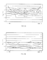
- Fig. 5A is a graph illustrating the hardness of the cushion pad 1 (the rear support portion 3).
- S 25 the ratio of the seating center portion 21a to the hardness
- the horizontal axis denotes the sampling positions of the respective test pieces in the right-left direction in the rear support portion 3.
- the vertical axis (the Y-axis) denotes S 25 (the ratio).
- the solid line denotes S 25 of the respective test pieces in the seating portion 21.
- the one dot chain line denotes S 25 of the respective test pieces in the upper center portion 22.
- the two-dot chain line denotes S 25 of the respective test pieces in the lower center portion 23.
- the dashed line denotes S 25 of the respective test pieces in the bottom surface portion 24.
- the seating portion 21 has an approximately constant hardness over the right-left direction.
- the upper center portion 22, the lower center portion 23, and the bottom surface portion 24 have hardness gradients where the hardnesses gradually increase toward the outer side in the right-left direction.
- the hardness gradients of the lower center portion 23 and the bottom surface portion 24 are set to be large. This allows providing a comfortable holding property to the seated person H.
- the hardness of the first portion 25 positioned on the seating surface 11 side of the thickness center 13 is set to a value smaller than the value of the hardness of the second portion 26 positioned on the bottom surface 12 side of the thickness center 13.
- the hardness of the first side portion 27 is set to a value smaller than the value of the hardness of the second side portion 28.
- the hardnesses of the first portion 25 and the first side portion 27, which are positioned on the seating surface 11 side are set to values smaller than the values of the hardnesses of the second portion 26 and the second side portion 28, which are positioned on the bottom surface 12 side. This allows providing the soft feeling during seating to the seated person H.
- first portion 25 and the first side portion 27 are positioned on the seating surface 11 side of the thickness center 13. This allows ensuring a close contact property with the buttocks. Furthermore, the second portion 26 and the second side portion 28 are positioned on the bottom surface 12 side of the thickness center 13. This allows improving the holding property of the buttocks and reducing the wobbling feeling.
- the ratio of the hardness of the first side portion 27 to the hardness of the first portion 25 is set to a value smaller than the value of the ratio of the hardness of the second side portion 28 to the hardness of the second portion 26.
- the first side portion 27 and the second side portion 28 are positioned in the portion compressed in the above-below direction (the arrow U-D direction) by the seat pressure of the seated person H.
- the ischial tuberosity portions T1 and T2 of the seated person H seated on the seating surface 11 provide the highest seat pressure.
- the first side portion 27 and the second side portion 28 are positioned on the outer side in the right-left direction with respect to the right and left ischial tuberosity portions T1 and T2 of the seated person H seated on the seating surface 11. This allows reducing the seat pressure in the portion providing the highest seat pressure.
- the right and left ischial tuberosity portions T1 and T2 can be restrained by the first side portion 27 and the second side portion 28 from the outer side in the right-left direction. This allows improving the holding property of the buttocks so as to ensure good seating comfort while reducing the wobbling feeling.
- the hardness of the bottom center portion 24a positioned in the center of the bottom surface portion 24 in the right-left direction is set to be equal to or more than a hardness 1.1 times as large as the hardness of the seating center portion 21a positioned in the center of the seating portion 21 in the right-left direction. This allows the bottom surface portion 24 to firmly support the buttocks so as to reduce sinking of the buttocks. It is to be noted that, the hardness of the bottom center portion 24a is set to be equal to or less than a hardness twice as large as, preferably, equal to or less than a hardness 1.5 times as large as the hardness of the seating center portion 21a. This is because the excessively hard bottom center portion 24a provides poor seating comfort.
- the hardnesses in the respective portions positioned on the vertical line passing through the first portion 25 and the second portion 26 (on the straight line parallel to the Y-axis) gradually increase in the order corresponding to the seating portion 21 (the upper center portion 22), the lower center portion 23, and the bottom surface portion 24. This consequently allows obtaining the soft feeling during seating on the seating surface 11 (see Fig. 2 ) side and reducing sinking of the buttocks on the bottom surface 12 side.
- the hardnesses in the respective portions positioned on the vertical line passing through the first side portion 27 and the second side portion 28 (on the straight line parallel to the Y-axis) gradually increase in the order corresponding to the seating portion 21, the upper center portion 22, the lower center portion 23, and the bottom surface portion 24. This consequently allows obtaining the soft feeling during seating on the seating surface 11 side and improving the holding property of the buttocks on the bottom surface 12 side.
- the hardnesses (the hardnesses of the respective test pieces in the lower center portion 23) in the respective portions positioned on the horizontal line passing through the second portion 26 gradually increase from the second portion 26 toward the outer side in the right-left direction. This consequently allows ensuring holding property of the buttocks of the seated person H on the bottom surface 12 side (the lower center portion 23) of the rear support portion 3 so as to reduce the wobbling feeling.
- the rear support portion 3 is integrally molded by the single foamed synthetic resin material. This allows eliminating the processes for burying an insert material having a large hardness and for laminating a plurality of layers having different hardnesses in the manufacturing process of the cushion pad. This allows saving the manufacturing cost of the cushion pad 1.
- the cushion pad 1 is manufactured by injecting a compound liquid (foamable raw liquid) containing a polyol component, a polyisocyanate component, a foaming agent, and a catalyst to a molding die (the lower die) and foam molding inside the molding die (the lower die and the upper die). It is to be noted that, the cushion pad 1 can be molded integrally with the bottom surface 12 by preliminarily attaching a reinforced fabric such as coarse wool cloth and nonwoven fabric on the molding die (the upper die). Furthermore, after the cushion pad 1 is molded, a reinforced fabric can be bonded to the bottom surface 12.
- the polyol component can employ polyetherpolyol, polyester polyol, polycarbonate polyol, polyolefin polyol, and lactone-based polyol.
- polyetherpolyol is preferred because the raw material cost is low and the water resistance is excellent.
- polymer polyol can be used in combination.
- Polymer polyol employs, for example, material obtained by graft-copolymerizing a polymer component such as polyacrylonitrile and acrylonitrile-styrene copolymer to polyetherpolyol containing polyalkylene oxide.
- the weight average molecular weight of the polyol component is preferred to be 6000 to 10000. In the case where the weight average molecular weight is less than 6000, the flexibility of the obtained foam is lost such that degradation in physical property or a decrease in elastic performance is likely to occur. In the case where the weight average molecular weight exceeds 10000, the hardness of the foam is likely to decrease.
- the polyisocyanate component can employ publicly-known various polyfunctional aliphatic, alicyclic, and aromatic isocyanates.
- tolylene diisocyanate TDI
- methylene diphenyl diisocyanate MDI
- dicyclohexylmethane diisocyanate triphenyl diisocyanate
- xylene diisocyanate polymethylene polyphenylene polyisocyanate, hexamethylene diisocyanate
- isophorone diisocyanate ortho-toluidine diisocyanate, naphthylene diisocyanate, xylylene diisocyanate, lysine diisocyanate, and similar component
- one kind may be used alone or two or more kinds may be used in combination.
- MDI-based isocyanates typified by methylene diphenyl diisocyanate include, for example, methylene diphenyl diisocyanate (pure MDI), polyphenylene polymethylene polyisocyanate (polymeric MDI), polymeric body of these, urethane-modified body of these, urea-modified body, allophanate-modified body, biuret modified body, carbodiimide-modified body, uretonimine-modified body, uretdione-modified body, isocyanurate-modified body, and the mixture of two or more kinds of these.
- pure MDI methylene diphenyl diisocyanate
- polymeric MDI polymeric MDI
- polymeric body of these urethane-modified body of these, urea-modified body, allophanate-modified body, biuret modified body, carbodiimide-modified body, uretonimine-modified body, uretdi
- terminal isocyanate prepolymer can also be used.
- Terminal isocyanate prepolymer is obtained by preliminarily causing a reaction of: polyol such as polyetherpolyol and polyester polyol; and polyisocyanate (such as TDI-based isocyanate and MDI-based isocyanate).
- polyol such as polyetherpolyol and polyester polyol
- polyisocyanate such as TDI-based isocyanate and MDI-based isocyanate.
- Use of terminal isocyanate prepolymer allows controlling the viscosity of the compound liquid (foamable raw liquid), the primary structure of polymer, the compatibility, and it is preferable.
- the polyisocyanate component preferably employs MDI-based isocyanate, which allows molding an elastic foam having a small rebound resilience compared with the elastic foam by TDI-based isocyanate.
- MDI-based material:TDI-based material 100:0 to 75:25, preferably, 100:0 to 80:20.
- the mass ratio of the TDI-based material in the polyisocyanate component becomes larger than 20/100, the wobbling feeling in the obtained product tends to decrease.
- the mass ratio of the TDI-based material becomes larger than 25/100, this trend becomes remarkable.
- the isocyanate index (the percentage of the equivalence ratio of the isocyanate group to the active hydrogen group) of the polyisocyanate component is set to, for example, 85 to 130.
- the foaming agent mainly employs water.
- molding can also be performed by concomitantly using a small amount of a low boiling point organic compound such as cyclopentane, normal pentane, isopentane, and HFC-245fa or using a gas loading device so as to mix and dissolve air, nitrogen gas, liquefied carbon dioxide, or similar material in the raw liquid.
- a low boiling point organic compound such as cyclopentane, normal pentane, isopentane, and HFC-245fa
- the preferred addition amount of the foaming agent depends on the set density of the obtained product, but is normally 0.5 to 15 mass% with respect to the polyol component.
- the catalyst can employ various urethane catalysts that are publicly-known in this field.
- reactive amine such as triethylamine, tripropylamine, tributylamine, N-methylmorphiline, N-ethylmorpholine, dimethylbenzylamine, N,N,N',N'-tetramethylhexamethylenediamine, N,N,N',N',N''-pentamethyldiethylenetriamine, and bis-(2-dimethylaminoethyl) ether, or organic acid salt of these; metal carboxylate such as potassium acetate and potassium octoate, or an organic metal compound such as stannous octoate, dibutyl tin dilaurate, and zinc naphthenate can be employed.
- an amine catalyst having an active hydrogen group such as N,N-dimethylethanolamine and N,N-diethylethanolamine is also preferred. The preferred addition amount of the catalyst is 0.01 to 10 mass% with respect
- a polyvalent active hydrogen compound having a low molecular weight is used as a crosslinking agent.
- the crosslinking agent facilitates the adjustment of the spring property of the cushion pad.
- the crosslinking agent employs, for example: polyhydric alcohols such as ethylene glycol, propylene glycol, 1,4-butanediol, trimethylolpropane, and glycerin; a compound obtained by polymerizing ethylene oxide or propylene oxide using these polyhydric alcohols as an initiator; and alkanolamines such as monoethanolamine, diethanolamine, triethanolamine, and N-methyldiethanolamine. These compounds can be used alone or as the mixture of two or more kinds.
- a foam stabilizer is used as necessary.
- the foam stabilizer can employ an organic silicon-based surfactant that is publicly-known in this field.
- the preferred addition amount of the foam stabilizer is 0.1 to 10 mass% with respect to the polyol component.
- a flame retardant, a plasticizer, a cell opener, an oxidation inhibitor, an ultraviolet absorber, a colorant, various fillers, an internal mold release agent, or other process aids are used.
- the compositions of the compound liquid (foamable raw liquid) for molding the cushion pad in Examples and Comparative examples are shown in Table 1.
- the numerical value shown in Table 1 denotes the unit mass (mass ratio).
- the isocyanate amount in Table 1 is the mass ratio of isocyanate to polyol (to 100 of polyol).
- Isocyanates 1 to 3 are the component ratios to the entire isocyanate.
- Example 1 Example 2
- Example 3 Example 4 Comparative example 1 Comparative example 2 Comparative example 3 polyol 1 80 80 80 80 2 60 60 60 3 20 20 20 20 40 40 40 crosslinking agent 1 1.0 1.0 1.0 1.0 1.5 1.5 1.5 2 2.5 2.5 2.5 2.5 cell opener 2.0 2.0 2.0 2.0 foam stabilizer 1 1.0 1.0 1.0 1.0 1.0 1.0 1.0 catalyst 1 0.45 0.45 0.45 0.40 0.40 0.40 2 0.05 0.05 0.05 0.05 0.05 0.05 0.05 0.05 0.05 0.05 0.05 0.05 0.05 0.05 0.05 0.05 0.05 0.05 0.05 0.05 0.05 0.05 0.05 0.05 0.05 0.05 0.05 0.05 0.05 0.05 0.05 0.05 0.05 0.05 0.05 0.05 0.05 0.05 0.05 0.05 0.05 0.05 0.05 0.05 0.05 0.05 0.05 0.05 0.05 0.05 0.05 0.05 0.05 0.05 0.05 0.05 0.05 0.05 0.05 0.05 0.05 0.05 0.05 2.9 2.5 2.5 2.5 2.5 isocyanate amount 49.9 49.9 49.9 49.9 37.1 3
- Fig. 3 and Fig. 5A are diagrams illustrating the hardness of the cushion pad in Example 3.
- Fig. 5B is a graph illustrating the hardness of the cushion pad in Comparative example 1.
- the cushion pad in Comparative example 1 has a seating portion L1, an upper center portion L2, a lower center portion L3, and a bottom surface portion L4 from the seating surface, on which the seated person H is seated, toward the bottom surface.
- the seating portion L1 is a portion in contact with the lower die of the molding die.
- the bottom surface L4 is a portion in contact with the upper die of the molding die.
- Fig. 5B is a graph illustrating the plot of S 25 of the respective test pieces when S 25 in the center portion in the right-left direction of the seating portion L1 is set to 1.
- the horizontal axis (the X-axis) denotes the sampling positions in the right-left direction of the respective test pieces in the rear support portion
- the vertical axis (the Y-axis) denotes S 25 (by ratio).
- the solid line denotes S 25 of the respective test pieces in the seating portion L1.
- the one dot chain line denotes S 25 of the respective test pieces in the upper center portion L2.
- the two-dot chain line denotes S 25 of the respective test pieces in the lower center portion L3.
- the dashed line denotes S 25 of the respective test pieces in the bottom surface portion L4.
- the cushion pad in Comparative example 1 was found to have the largest hardness in the seating portion L1 and the second largest hardness in the bottom surface portion L4. Furthermore, the upper center portion L2 and the lower center portion L3 were found to have hardnesses smaller than those hardnesses. Furthermore, it was found that the bottom surface portion L4 had a slightly larger hardness on the outer side in the right-left direction than the hardness in the center in the right-left direction while the seating portion L1, the upper center portion L2, and the lower center portion L3 had approximately constant hardnesses over the right-left direction.
- the cushion pad in Comparative example 1 provides poor fit feeling due to the hardest seating portion L1 and further provides wobbling feeling in the lateral direction to the seated person due to the hard seating portion L1 and bottom surface portion L4 (the surface layer) and the soft upper center portion L2 and lower center portion L3 (the core layer).
- the cushion pad in Example 3 is set to have the softest seating portion 21 and become harder in the order corresponding to the upper center portion 22, the lower center portion 23, and the bottom surface portion 24 so as to be excellent in fit feeling and is causes firmly supporting by the upper center portion 22, the lower center portion 23, and the bottom surface portion 24 so as to reduce the wobbling feeling. Furthermore, it is inferred that the upper center portion 22, the lower center portion 23, and the bottom surface portion 24 allow improving the holding property due to the larger hardness on the outer side in the right-left direction than the hardness in the center in the right-left direction.
- Fig. 6 is a cross-sectional view of a cushion pad 30 according to the second embodiment.
- the cushion pad 30 includes: a seating portion 31, on which the seated person is seated; an upper center portion 32, which is arranged under the seating portion 31; a lower center portion 33, which is arranged under the upper center portion 32; and a bottom surface portion 34, which is arranged under the lower center portion 33.
- a side support portions 35 are arranged on the outer side of the seating portion 31 in the right-left direction.
- the seating portion 31, the upper center portion 32, the lower center portion 33, and the bottom surface portion 34 are bonded to one another to be laminated.
- the side support portions 35 are bonded to both right and left sides of the upper center portion 32.
- the materials are selected such that the force S 25 during compression to 25% increases in this order.
- the seating portion 31, the upper center portion 32, the lower center portion 33, and the bottom surface portion 34 are all formed in a tabular shape using flexible polyurethane foam (molded urethane).
- the hardness distributions of the seating portion 31, the upper center portion 32, the lower center portion 33, and the bottom surface portion 34 are set similarly to the hardness distributions in the cushion pad 1 (the rear support portion 3) according to the first embodiment. Therefore, the description of these is omitted.
- the cushion pad 30 in the second embodiment allows achieving the operation and effect similar to those of the cushion pad 1 in the first embodiment.
- cushion pads 1 and 30 to be mounted on a vehicle have been described, this should not necessarily be construed in a limiting sense.
- the cushion pads 1 and 30 may obviously be applied to a cushion material equipped with another transportation means such as a vehicle (such as a railway vehicle), a ship, and an aircraft other than the automobile or applied to a cushion material of furniture or similar product.
- the integrally molded cushion pad 1 (the rear support portion 3) made of foamed synthetic resin (made of flexible polyurethane foam) is sectionalized into four layers in the above-below direction, the respective layers are sectionalized into 15 pieces in the right-left direction, and 60 test pieces are sampled to measure the hardness, the number (the number of layers or the number of sections in the right-left direction) and the size of the test pieces are not limited to these.
- the size of the test piece can be set to a size that allows measurement of the hardness as necessary.
- the number of the test pieces can be set to the number that allows sampling of the test piece having this size as necessary. It is to be noted that, taking into consideration the size the cushion pad 1 (the rear support portion 3), it is appropriate to sectionalize the rear support portion 3 into four layers or five layers. Furthermore, the size of the test piece is preferred to have 20 to 25 mm in length for each side of the quadrangular prism.
- first portion 25 and the first side portion 27 are disposed in the upper center portion 22 while the second portion 26 and the second side portion 28 are disposed in the lower center portion 23.
- the positions of the first portion 25, the first side portion 27, the second portion 26, and the second side portion 28 are not limited to these. These positions can be set corresponding to the number of layers to sectionalize the cushion pad 1 (the rear support portion 3) in the above-below direction as necessary.
- the side support portions 5 and 35 are disposed in the cushion pads 1 and 30, this should not necessarily be construed in a limiting sense.
- the side support portions 5 and 35 can be omitted. This is because the cushion pads 1 and 30 (the support portion 2) are excellent in holding property (restraint property) in the right-left direction, that is, of the side portions of the buttocks and the thigh.
- the front support portion 4 can also be set to have a hardness distribution similar to that of the rear support portion 3. This allows reducing not only the wobbling feeling of the buttocks but also the wobbling feeling of the thigh.
- the other materials include, for example, slab urethane formed by cutting off the molded flexible polyurethane foam, chip urethane formed by crushing the listing and similar material generated in the manufacturing process of the flexible polyurethane foam, a three dimensional net-like body constituted of a plurality of three-dimensionally intertwined fibers made of synthetic resin, a fiber body such as solid cotton, a synthetic resin-made elastic body such as urethane rubber and thermoplastic elastomer. Laminating these materials allows obtaining a predetermined hardness distribution.
- the hardnesses, the densities, and the shapes of the seating portion 31, the upper center portion 32, the lower center portion 33, and the bottom surface portion 34 are set as necessary by, for example, selecting materials, designing the cavity shape of the molding die, cutting, and machining.
- the respective layers of the seating portion 31, the upper center portion 32, the lower center portion 33, and the bottom surface portion 34 are formed in a tabular shape. This should not necessarily be construed in a limiting sense. These layers can obviously be formed in a curved plate shape. This is because the seating portion 31, the upper center portion 32, the lower center portion 33, and the bottom surface portion 34 can be molded into a predetermined shape by mold forming, cutting, or similar method. It is obviously possible to form these layers in a curved plate shape so as to dispose the portion having a large hardness on the lateral side of the buttocks of the seated person.
Abstract
Description
- The present invention relates to a cushion pad, particularly, to a cushion pad that improves a holding property and reduces a wobbling feeling.
- A cushion pad used for, for example, a seat and a chair such as furniture equipped with transportation means such as a vehicle, a ship, and an aircraft might provide wobbling feeling in the lateral direction to a seated person. For example, in a cushion pad mounted on a vehicle, a vibration input in a low frequency band (for example, approximately 1 Hz) when the vehicle travels around a gentle curve or changes the lane might deform the cushion pad so as to provide wobbling feeling such as side slipping and rolling around the roll axis. The wobbling feeling is a factor affecting the controllability and the stability. To reduce this wobbling feeling, there is a technology that sets tan δ with respect to the vibration in the low frequency band to a predetermined range (in Patent Literature 1).
- [Patent Literature 1]
JP-A No. 2012-45104 - However, there is a request to further improve the holding property (the restraint property) relative to the above-described conventional technology.
- The present invention has been made to respond to the above-described request, and it is an object of the present invention to provide a cushion pad that improves the holding property and reduces the wobbling feeling.
- To achieve this object, with the cushion pad according to
claim 1, a support portion has: a seating surface on which a seated person is seated; and a bottom surface on an opposite side to the seating surface. The support portion has a first portion whose hardness is set to a value smaller than a value of a hardness of a second portion. The first portion is positioned on the seating surface side of a thickness center as a center in a thickness direction sandwiched between the seating surface and the bottom surface. The second portion is a portion positioned on a vertical line passing through the first portion. The second portion is positioned on the bottom surface side of the thickness center. The first portion and the second portion are positioned in a center in a right-left direction viewed from the seated person seated on the seating surface. A first side portion has a hardness set to a value smaller than a value of a hardness of a second side portion. The first side portion is a portion positioned on a horizontal line passing through the first portion. The first side portion is positioned on an outer side of the first portion in the right-left direction. The second side portion is a portion on a vertical line passing through the first side portion. The second side portion is positioned on a horizontal line passing through the second portion. The hardness is a force during compression to 25% measured in compliance with E method specified in JIS K6400-2 (the 2012 edition) using a quadratic-prism-shaped test piece sampled by equally dividing the support portion. - The hardnesses of the first portion and the first side portion, which are positioned on the seating surface side, are set to the values smaller than the values of the hardnesses of the second portion and the second side portion, which are positioned on the bottom surface side. This allows providing soft feeling during seating to the seated person. Furthermore, the first portion and the first side portion are positioned on the seating surface side of the thickness center. This allows ensuring close contact property with the seated person. Furthermore, the second portion and the second side portion are positioned on the bottom surface side of the thickness center. This provides an effect that allows improving the holding property and reducing the wobbling feeling.
- With the cushion pad according to
claim 2, a ratio of the hardness of the first side portion to the hardness of the first portion is set to a value smaller than a value of a ratio of the hardness of the second side portion to the hardness of the second portion. The first portion and the first side portion allow reducing the seat pressure of the seated person. In addition to the effect ofclaim 1, this provides an effect that allows improving the soft feeling so as to ensure good seating comfort. - With the cushion pad according to
claim 3, the first side portion and the second side portion are positioned in the portions compressed by the seat pressure of the buttocks of the seated person. Normally, the ischial tuberosity portion of the seated person seated on the seating surface provides the largest seat pressure. However, the first side portion and the second side portion are positioned on the outer side in the right-left direction of the right and left ischial tuberosity portions of the seated person seated on the seating surface. This allows reducing the seat pressure in the portion providing the highest seat pressure in the buttocks of the seated person. Furthermore, the first side portion and the second side portion allow restraining the right and left ischial tuberosity portions from the outer side in the right-left direction. In addition to the effect ofclaim 2, this provides an effect that allows improving the holding property of the buttocks so as to ensure good seating comfort while reducing the wobbling feeling. - With the cushion pad according to
claim 4, a hardness of a portion positioned in a center in the right-left direction of a bottom surface portion including the bottom surface is equal to or more than a hardness 1.1 times as large as a hardness of a portion positioned in a center in the right-left direction of a seating portion including the seating surface. Accordingly, in addition to the effect of any one ofclaims 1 to 3, this provides an effect that allows the bottom surface portion to support the buttocks and allows reducing sinking of the buttocks. - With the cushion pad according to
claim 5, a hardness of each portion positioned on a vertical line passing through the first portion and the second portion gradually increases from the seating surface side toward the bottom surface side. As a result, in addition to the effect of any one ofclaims 1 to 4, this provides an effect that allows obtaining soft feeling during seating on the seating surface side of the support portion and reducing sinking of the buttock on the bottom surface side of the support portion. - With the cushion pad according to
claim 6, a hardness of each portion positioned on a vertical line passing through the first side portion and the second side portion gradually increases from the seating surface side toward the bottom surface side. As a result, in addition to the effect of any one ofclaims 1 to 5, this provides an effect that allows obtaining soft feeling during seating on the seating surface side of the support portion and improving the holding property on the bottom surface side of the support portion. - With the cushion pad according to claim 7, a hardness of each portion positioned on a horizontal line passing through the second portion gradually increases from the second portion toward an outer side in the right-left direction. As a result, in addition to the effect of any one of
claims 1 to 6, this provides an effect that allows ensuring holding property of the buttocks of the seated person on the bottom surface side of the support portion so as to reduce the wobbling feeling. - With the cushion pad according to claim 8, the support portion is integrally molded by a single foamed synthetic resin material. Hence, this allows eliminating the processes for burying an insert material having a large hardness and for laminating a plurality of layers having different hardnesses in the manufacturing process of the cushion pad. Accordingly, in addition to the effect of any one of
claims 1 to 7, this provides an effect that allows saving the manufacturing cost. -
-
Fig. 1 is a plan view of a cushion pad according to a first embodiment of the present invention. -
Fig. 2 is a schematic diagram where test pieces as an equally divided support portion are overlapped with a cross-sectional view of the cushion pad taken along the line II-II inFig. 1 . -
Fig. 3 is a diagram illustrating a hardness distribution of a support portion. -
Fig. 4 is a schematic diagram of the cushion pad illustrating the seated state of a seated person. -
Fig. 5A is a graph illustrating the hardness of the cushion pad, andFig. 5B is a graph illustrating the hardness of a cushion pad in a comparative example. -
Fig. 6 is a cross-sectional view of a cushion pad according to a second embodiment. - Hereinafter, a description will be given of preferred embodiments of the present invention with reference to the accompanying drawings.
Fig. 1 is a plan view of acushion pad 1 according to a first embodiment of the present invention. In this embodiment, a description will be given of thecushion pad 1 mounted on a vehicle (in particular, an automobile) having vibration. Note that, the respective arrows U-D, L-R, and F-B inFig. 1 denote the above-below direction, the right-left direction, and the front-rear direction of a vehicle (not shown) on which thecushion pad 1 is mounted (the same applies toFig. 2 andFig. 4 ). - As illustrated in
Fig. 1 , thecushion pad 1, which is a base material integrally molded with the flexible polyurethane foam (one type of foamed synthetic resin material), includes: asupport portion 2, which supports the buttocks and the back side of the thigh of a seated person H; andside support portions 5, which are arranged on both sides of thesupport portion 2 in the right-left direction (the arrow L-R direction). Theside support portions 5 are portions that support the side portions of the thigh and the buttocks. - The
support portion 2 is partitioned by a lateral groove 8, which extends in the right-left direction, into: arear support portion 3, which supports the buttocks; and afront support portion 4, which supports the back side of the thigh. Therear support portion 3 supports the buttocks including the right and left ischial tuberosity portions T1 and T2 of the seated person H in a seated state. In therear support portion 3 and thefront support portion 4, the respective lateral grooves 7 and 9 are depressed parallel to the lateral groove 8. In the boundary portion between thesupport portion 2 and theside support portion 5, a pair oflongitudinal grooves 6, which extends in the front-rear direction (the arrow F-B direction) is formed. The pair oflongitudinal grooves 6 couples to the respective both ends of the lateral grooves 7, 8, and 9. Thelongitudinal groove 6 and the lateral grooves 7, 8, and 9 are portions for pulling and securing a surface skin (not shown) such as fabric, artificial leather, or leather to thecushion pad 1. - The
cushion pad 1 has a feature in the hardness distributions in the above-below direction (the arrow U-D the direction) and the right-left direction (the arrow L-R the direction) of the support portion 2 (the rear support portion 3). In this embodiment, a small test piece sampled from the rear support portion 3 (molded object) is used to measure the hardness so as to obtain the hardness distribution. Referring toFig. 2 , the sampling positions of the test piece will be described.Fig. 2 is a schematic diagram where the test pieces sampled by equally dividing the support portion 2 (the rear support portion 3) are overlapped with a cross-sectional view of thecushion pad 1 taken along the line II-II inFig. 1 . - As illustrated in
Fig. 2 , therear support portion 3 is a portion formed on the inner side of the pair oflongitudinal grooves seating surface 11, on which the seated person H is seated, and abottom surface 12 on the opposite side of theseating surface 11, and has a cross section formed in an approximately horizontally long rectangular shape. Therear support portion 3 is equally divided in the above-below direction (the arrow U-D direction) and the right-left direction (the arrow L-R direction) to measure the hardness. A plurality of test pieces is sampled. - In this embodiment, the
rear support portion 3 in the above-below direction (the arrow U-D direction) is equally sectionalized into four layers (20 mm for each thickness). Those layers in the right-left direction (the arrow L-R direction) are equally sectionalized into 15 pieces (20 mm for each width). In the respective layers, the lengths in the front-rear direction (the perpendicular direction on the paper inFig. 2 ) are set to 20 mm to sample 60 test pieces in a quadrangular prism shape (cube) having 20 mm for each side. The four layers formed by equally dividing therear support portion 3 into four portions in the above-below direction (the arrow U-D direction) are: a seatingportion 21 including theseating surface 11; anupper center portion 22 positioned under theseating portion 21; alower center portion 23 positioned under theupper center portion 22; and abottom surface portion 24, which is positioned under thelower center portion 23 and includes thebottom surface 12. The seatingportion 21 and theupper center portion 22 are positioned on theseating surface 11 side of athickness center 13 as the center of therear support portion 3 in the thickness direction. Thelower center portion 23 and thebottom surface portion 24 are positioned on thebottom surface 12 side of thethickness center 13. - For the sampled test piece, the force during compression to 25% is measured in compliance with E method specified in JIS K6400-2 (the 2012 edition). JIS K6400-2 is Japanese Industrial Standards made by based on ISO 2439 (Fourth Edition: issued in 2008), ISO 3386-1 (Second Edition: issued in 1986), and ISO 3386-2 (Second Edition: issued in 1997). According to this testing method, the test piece placed on a support plate (not shown) larger than the test piece while facing the above-below direction (the arrow U-D direction) is pre-compressed by a pressure plate (not shown) having a pressure surface larger than the top surface of the test piece, and then is pressurized to have 75 ± 2.5% of the thickness. The force when the test piece is pressurized to have 25 ± 1% of the thickness is assumed to be a force S25 (unit: N) under compression of the test piece to 25%. In this description, the force (hereinafter referred to as "S25") during compression to 25% is defined as "hardness."
- It is to be noted that, the test piece sampled from the
bottom surface portion 24 is placed on a support plate (not shown) side while facing thebottom surface 12 side after a reinforced fabric (not shown) molded integrally with thebottom surface 12 is removed. Then, the hardness is measured. This is for reducing the influence of the reinforced fabric. Furthermore, the test pieces (to which "cross" is attached inFig. 2 ) sampled from both ends of thelower center portion 23 and thebottom surface portion 24 in the right-left direction have hardnesses larger than the hardnesses of the other test pieces, and thus are eliminated. - Furthermore, for convenience, the portion that is: the portion positioned in the center in the right-left direction (the arrow L-R direction) of the
rear support portion 3; and the portion (the test piece) positioned on theseating surface 11 side of thethickness center 13, is referred to as afirst portion 25. The portion that is: the portion positioned on the vertical line (the straight line in the arrow U-D direction) passing through thefirst portion 25; and the portion (the test piece) positioned on thebottom surface 12 side of thethickness center 13, is referred to as asecond portion 26. The portion that is: the portion positioned on the horizontal line (the straight line in the arrow L-R direction) passing through the first portion 25 (within the upper center portion 22); and the portion (the test piece) positioned on the outer side of thefirst portion 25 in the right-left direction, is referred to as afirst side portion 27. The portion that is: the portion on the vertical line passing through thefirst side portion 27; and the portion (the test piece) positioned on thebottom surface 12 side of thethickness center 13, is referred to as asecond side portion 28. The portion (the test piece) positioned in the center of theseating portion 21 in the right-left direction is referred to as aseating center portion 21a. The portion (the test piece) positioned in the center of thebottom surface portion 24 in the right-left direction is referred to as abottom center portion 24a. - Referring to
Fig. 3 , the following describes the hardness distribution of the support portion 2 (the rear support portion 3) based on S25 (the measured values) of the respective test pieces.Fig. 3 is a diagram illustrating the hardness distribution of the support portion. Note that, inFig. 3 , the values (unit: N/cm2) obtained by dividing the hardnesses (unit: N) of the respective test pieces by the cross-sectional areas (unit: cm2) of the test pieces are divided into four sections. These sections are displayed by four levels of shadings.Fig. 3 illustrates the state where a darker color indicates a larger hardness. - As illustrated in
Fig. 3 , therear support portion 3 is formed to have a larger hardness in the order corresponding to theseating portion 21, theupper center portion 22, thelower center portion 23, and thebottom surface portion 24. Furthermore, theupper center portion 22, thelower center portion 23, and thebottom surface portion 24 are formed such that the hardness increases toward the outer side of the center in the right-left direction. As a result, therear support portion 3 has the hardness increasing from theseating surface 11 toward thebottom surface 12, and has a mortar-shaped hardness distribution where the hardness on the outer side of the center in the right-left direction increases. - The following describes the
cushion pad 1 on which the seated person H is seated by referring toFig. 4. Fig. 4 is a schematic diagram of thecushion pad 1 illustrating the seated state of the seated person H. Note that, inFig. 4 , the illustration of theside support portion 5 is omitted. - As illustrated in
Fig. 4 , when the seated person H is seated on the cushion pad 1 (the rear support portion 3), therear support portion 3 is compressed in the above-below direction (the arrow U-D direction) by the weight of this seated person H. Therear support portion 3 is set to increase in hardness from theseating surface 11 toward the bottom surface 12 (seeFig. 3 ). This allows providing close contact feeling (fit feeling) with the buttocks while providing soft feeling mainly by the seatingportion 21 and theupper center portion 22. Furthermore, the seatingportion 21, theupper center portion 22, thelower center portion 23, and thebottom surface portion 24 deform to ensure the holding property (the restraint property) of the buttocks in the right-left direction (the arrow L-R direction) so as to reduce the wobbling feeling. - In particular, the
rear support portion 3 has the mortar-shaped hardness distribution where theupper center portion 22, thelower center portion 23, and thebottom surface portion 24 have the larger hardnesses on the outer side in the right-left direction relative to the center in the right-left direction. This allows improving the holding property of the buttocks. - Note that, as illustrated in
Fig. 4 , thefirst side portion 27 and thesecond side portion 28 are the portions compressed in the above-below direction by the seat pressure of the buttocks of the seated person H and are positioned on the outer side in the right-left direction (the arrow L-R direction) with respect to the right and left ischial tuberosity portions T1 and T2 of the seated person H in a seated state. - The following the hardness distribution of the cushion pad 1 (the rear support portion 3) by referring to
Fig. 5A in detail.Fig. 5A is a graph illustrating the hardness of the cushion pad 1 (the rear support portion 3). InFig. 5A , S25 (the ratio of theseating center portion 21a to the hardness) of the respective test pieces are plotted when the force S25 during compression to 25% of theseating center portion 21a (the portion in the center of theseating portion 21 in the right-left direction) is set to 1. InFig. 5A , the horizontal axis (the X-axis) denotes the sampling positions of the respective test pieces in the right-left direction in therear support portion 3. The vertical axis (the Y-axis) denotes S25 (the ratio). The solid line denotes S25 of the respective test pieces in theseating portion 21. The one dot chain line denotes S25 of the respective test pieces in theupper center portion 22. The two-dot chain line denotes S25 of the respective test pieces in thelower center portion 23. The dashed line denotes S25 of the respective test pieces in thebottom surface portion 24. - Note that, in
Fig. 5A , the hardnesses of the test pieces sampled from both the ends of theseating portion 21, theupper center portion 22, thelower center portion 23, and thebottom surface portion 24 in the right-left direction are not plotted. This is because these hardnesses are larger than the hardnesses of the other test pieces. - As illustrated in
Fig. 5A , the seatingportion 21 has an approximately constant hardness over the right-left direction. In contrast, theupper center portion 22, thelower center portion 23, and thebottom surface portion 24 have hardness gradients where the hardnesses gradually increase toward the outer side in the right-left direction. Compared with the hardness gradient of theupper center portion 22, the hardness gradients of thelower center portion 23 and thebottom surface portion 24 are set to be large. This allows providing a comfortable holding property to the seated person H. - Furthermore, the hardness of the
first portion 25 positioned on theseating surface 11 side of the thickness center 13 (seeFig. 2 ) is set to a value smaller than the value of the hardness of thesecond portion 26 positioned on thebottom surface 12 side of thethickness center 13. The hardness of thefirst side portion 27 is set to a value smaller than the value of the hardness of thesecond side portion 28. The hardnesses of thefirst portion 25 and thefirst side portion 27, which are positioned on theseating surface 11 side, are set to values smaller than the values of the hardnesses of thesecond portion 26 and thesecond side portion 28, which are positioned on thebottom surface 12 side. This allows providing the soft feeling during seating to the seated person H. Furthermore, thefirst portion 25 and thefirst side portion 27 are positioned on theseating surface 11 side of thethickness center 13. This allows ensuring a close contact property with the buttocks. Furthermore, thesecond portion 26 and thesecond side portion 28 are positioned on thebottom surface 12 side of thethickness center 13. This allows improving the holding property of the buttocks and reducing the wobbling feeling. - The ratio of the hardness of the
first side portion 27 to the hardness of thefirst portion 25 is set to a value smaller than the value of the ratio of the hardness of thesecond side portion 28 to the hardness of thesecond portion 26. As a result, thefirst portion 25 and thefirst side portion 27 allow reducing the seat pressure, thus improving the soft feeling and enhancing the seating comfort. - The
first side portion 27 and the second side portion 28 (seeFig. 4 ) are positioned in the portion compressed in the above-below direction (the arrow U-D direction) by the seat pressure of the seated person H. Normally, the ischial tuberosity portions T1 and T2 of the seated person H seated on theseating surface 11 provide the highest seat pressure. However, thefirst side portion 27 and thesecond side portion 28 are positioned on the outer side in the right-left direction with respect to the right and left ischial tuberosity portions T1 and T2 of the seated person H seated on theseating surface 11. This allows reducing the seat pressure in the portion providing the highest seat pressure. Furthermore, the right and left ischial tuberosity portions T1 and T2 can be restrained by thefirst side portion 27 and thesecond side portion 28 from the outer side in the right-left direction. This allows improving the holding property of the buttocks so as to ensure good seating comfort while reducing the wobbling feeling. - Here, the hardness of the
bottom center portion 24a positioned in the center of thebottom surface portion 24 in the right-left direction is set to be equal to or more than a hardness 1.1 times as large as the hardness of theseating center portion 21a positioned in the center of theseating portion 21 in the right-left direction. This allows thebottom surface portion 24 to firmly support the buttocks so as to reduce sinking of the buttocks. It is to be noted that, the hardness of thebottom center portion 24a is set to be equal to or less than a hardness twice as large as, preferably, equal to or less than a hardness 1.5 times as large as the hardness of theseating center portion 21a. This is because the excessively hardbottom center portion 24a provides poor seating comfort. - As illustrated in
Fig. 5A , the hardnesses in the respective portions positioned on the vertical line passing through thefirst portion 25 and the second portion 26 (on the straight line parallel to the Y-axis) gradually increase in the order corresponding to the seating portion 21 (the upper center portion 22), thelower center portion 23, and thebottom surface portion 24. This consequently allows obtaining the soft feeling during seating on the seating surface 11 (seeFig. 2 ) side and reducing sinking of the buttocks on thebottom surface 12 side. - Furthermore, the hardnesses in the respective portions positioned on the vertical line passing through the
first side portion 27 and the second side portion 28 (on the straight line parallel to the Y-axis) gradually increase in the order corresponding to theseating portion 21, theupper center portion 22, thelower center portion 23, and thebottom surface portion 24. This consequently allows obtaining the soft feeling during seating on theseating surface 11 side and improving the holding property of the buttocks on thebottom surface 12 side. - The hardnesses (the hardnesses of the respective test pieces in the lower center portion 23) in the respective portions positioned on the horizontal line passing through the
second portion 26 gradually increase from thesecond portion 26 toward the outer side in the right-left direction. This consequently allows ensuring holding property of the buttocks of the seated person H on thebottom surface 12 side (the lower center portion 23) of therear support portion 3 so as to reduce the wobbling feeling. - It is to be noted that, the
rear support portion 3 is integrally molded by the single foamed synthetic resin material. This allows eliminating the processes for burying an insert material having a large hardness and for laminating a plurality of layers having different hardnesses in the manufacturing process of the cushion pad. This allows saving the manufacturing cost of thecushion pad 1. - The following describes a method for manufacturing the
cushion pad 1. Thecushion pad 1 is manufactured by injecting a compound liquid (foamable raw liquid) containing a polyol component, a polyisocyanate component, a foaming agent, and a catalyst to a molding die (the lower die) and foam molding inside the molding die (the lower die and the upper die). It is to be noted that, thecushion pad 1 can be molded integrally with thebottom surface 12 by preliminarily attaching a reinforced fabric such as coarse wool cloth and nonwoven fabric on the molding die (the upper die). Furthermore, after thecushion pad 1 is molded, a reinforced fabric can be bonded to thebottom surface 12. - The polyol component can employ polyetherpolyol, polyester polyol, polycarbonate polyol, polyolefin polyol, and lactone-based polyol. One kind or the mixture of two or more kinds of these components can be used. Among these, polyetherpolyol is preferred because the raw material cost is low and the water resistance is excellent.
- As necessary, polymer polyol can be used in combination. Polymer polyol employs, for example, material obtained by graft-copolymerizing a polymer component such as polyacrylonitrile and acrylonitrile-styrene copolymer to polyetherpolyol containing polyalkylene oxide.
- The weight average molecular weight of the polyol component is preferred to be 6000 to 10000. In the case where the weight average molecular weight is less than 6000, the flexibility of the obtained foam is lost such that degradation in physical property or a decrease in elastic performance is likely to occur. In the case where the weight average molecular weight exceeds 10000, the hardness of the foam is likely to decrease.
- The polyisocyanate component can employ publicly-known various polyfunctional aliphatic, alicyclic, and aromatic isocyanates. For example, tolylene diisocyanate (TDI), methylene diphenyl diisocyanate (MDI), dicyclohexylmethane diisocyanate, triphenyl diisocyanate, xylene diisocyanate, polymethylene polyphenylene polyisocyanate, hexamethylene diisocyanate, isophorone diisocyanate, ortho-toluidine diisocyanate, naphthylene diisocyanate, xylylene diisocyanate, lysine diisocyanate, and similar component can be employed. Among these, one kind may be used alone or two or more kinds may be used in combination.
- MDI-based isocyanates typified by methylene diphenyl diisocyanate include, for example, methylene diphenyl diisocyanate (pure MDI), polyphenylene polymethylene polyisocyanate (polymeric MDI), polymeric body of these, urethane-modified body of these, urea-modified body, allophanate-modified body, biuret modified body, carbodiimide-modified body, uretonimine-modified body, uretdione-modified body, isocyanurate-modified body, and the mixture of two or more kinds of these.
- Furthermore, terminal isocyanate prepolymer can also be used. Terminal isocyanate prepolymer is obtained by preliminarily causing a reaction of: polyol such as polyetherpolyol and polyester polyol; and polyisocyanate (such as TDI-based isocyanate and MDI-based isocyanate). Use of terminal isocyanate prepolymer allows controlling the viscosity of the compound liquid (foamable raw liquid), the primary structure of polymer, the compatibility, and it is preferable.
- In this embodiment, the polyisocyanate component preferably employs MDI-based isocyanate, which allows molding an elastic foam having a small rebound resilience compared with the elastic foam by TDI-based isocyanate. In the case where the mixture of MDI-based isocyanate and TDI-based isocyanate is used, the mass ratio is set to MDI-based material:TDI-based material = 100:0 to 75:25, preferably, 100:0 to 80:20. As the mass ratio of the TDI-based material in the polyisocyanate component becomes larger than 20/100, the wobbling feeling in the obtained product tends to decrease. When the mass ratio of the TDI-based material becomes larger than 25/100, this trend becomes remarkable. It is to be noted that, the isocyanate index (the percentage of the equivalence ratio of the isocyanate group to the active hydrogen group) of the polyisocyanate component is set to, for example, 85 to 130.
- The foaming agent mainly employs water. As necessary, molding can also be performed by concomitantly using a small amount of a low boiling point organic compound such as cyclopentane, normal pentane, isopentane, and HFC-245fa or using a gas loading device so as to mix and dissolve air, nitrogen gas, liquefied carbon dioxide, or similar material in the raw liquid. The preferred addition amount of the foaming agent depends on the set density of the obtained product, but is normally 0.5 to 15 mass% with respect to the polyol component.
- The catalyst can employ various urethane catalysts that are publicly-known in this field. For example, reactive amine such as triethylamine, tripropylamine, tributylamine, N-methylmorphiline, N-ethylmorpholine, dimethylbenzylamine, N,N,N',N'-tetramethylhexamethylenediamine, N,N,N',N',N''-pentamethyldiethylenetriamine, and bis-(2-dimethylaminoethyl) ether, or organic acid salt of these; metal carboxylate such as potassium acetate and potassium octoate, or an organic metal compound such as stannous octoate, dibutyl tin dilaurate, and zinc naphthenate can be employed. Furthermore, an amine catalyst having an active hydrogen group such as N,N-dimethylethanolamine and N,N-diethylethanolamine is also preferred. The preferred addition amount of the catalyst is 0.01 to 10 mass% with respect to the polyol component.
- As necessary, a polyvalent active hydrogen compound having a low molecular weight is used as a crosslinking agent. The crosslinking agent facilitates the adjustment of the spring property of the cushion pad. The crosslinking agent employs, for example: polyhydric alcohols such as ethylene glycol, propylene glycol, 1,4-butanediol, trimethylolpropane, and glycerin; a compound obtained by polymerizing ethylene oxide or propylene oxide using these polyhydric alcohols as an initiator; and alkanolamines such as monoethanolamine, diethanolamine, triethanolamine, and N-methyldiethanolamine. These compounds can be used alone or as the mixture of two or more kinds.
- Furthermore, a foam stabilizer is used as necessary. The foam stabilizer can employ an organic silicon-based surfactant that is publicly-known in this field. The preferred addition amount of the foam stabilizer is 0.1 to 10 mass% with respect to the polyol component. Further, as necessary, a flame retardant, a plasticizer, a cell opener, an oxidation inhibitor, an ultraviolet absorber, a colorant, various fillers, an internal mold release agent, or other process aids are used.
- The following describes the present invention for more details using Examples. However, the present invention is not limited to these Examples. The compositions of the compound liquid (foamable raw liquid) for molding the cushion pad in Examples and Comparative examples are shown in Table 1. The numerical value shown in Table 1 denotes the unit mass (mass ratio). Furthermore, the isocyanate amount in Table 1 is the mass ratio of isocyanate to polyol (to 100 of polyol).
Isocyanates 1 to 3 are the component ratios to the entire isocyanate.[Table1] Example 1 Example 2 Example 3 Example 4 Comparative example 1 Comparative example 2 Comparative example 3 polyol 1 80 80 80 80 2 60 60 60 3 20 20 20 20 40 40 40 crosslinking agent 1 1.0 1.0 1.0 1.0 1.5 1.5 1.5 2 2.5 2.5 2.5 cell opener 2.0 2.0 2.0 2.0 foam stabilizer 1 1.0 1.0 1.0 1.0 2 1.0 1.0 1.0 catalyst 1 0.45 0.45 0.45 0.45 0.40 0.40 0.40 2 0.05 0.05 0.05 0.05 0.05 0.05 0.05 water 2.9 2.9 2.9 2.9 2.5 2.5 2.5 isocyanate amount 49.9 49.9 49.9 49.9 37.1 38.1 35.6 isocyanate 1 5 15 25 80 70 60 2 100 95 85 75 3 20 30 40 wobbling feeling Excellent Excellent Excellent Good Poor Poor Poor - polyol 1 : polyetherpolyol EP828 (made by Mitsui Chemicals, Inc.), weight average molecular weight 6000
- polyol 2 : polyetherpolyol EP330N (made by Mitsui Chemicals, Inc.) weight average molecular weight 5000
- polyol 3 : polymer polyol POP3623 (made by Mitsui Chemicals, Inc.) crosslinking agent 1 : diethanolamine
- crosslinking agent 2 : EL930 (made by ASAHI GLASS CO., LTD.) cell opener : EP505S (made by Mitsui Chemicals, Inc.)
- foam stabilizer 1 : SZ1336 (made by Dow Corning Toray Co.,Ltd.)
- foam stabilizer 2 : SZ1325 (made by Dow Corning Toray Co.,Ltd.)
- catalyst 1 : TEDA L33 (made by TOSOH CORPORATION)
- catalyst 2 : ToyocatET (made by TOSOH CORPORATION)
- isocyanate 1 : tolylene diisocyanate TDI-80 (made by Mitsui Chemicals, Inc.)
- isocyanate 2 :
polymeric MDI 2, 4' -MDI · 4, 4' -mixture of MDI - isocyanate 3 : polymeric MDI MR200 (made by Nippon Polyurethane Industry Co.,Ltd (TOSOH CORPORATION)))
- Respective these components were combined by an ordinary method using the mass ratios shown in Table 1 so as to be uniformly mixed. Subsequently, a predetermined amount of the mixture was injected to the molding die (the lower die) for a cushion pad in a predetermined shape and was foamed and hardened inside the cavity so as to obtain cushion pads in Examples 1 to 4 and Comparative examples 1 to 3. For all the cushion pads, wobbling feeling was evaluated by a sensory test when an examinee was seated. The evaluation of the wobbling feeling was ranked in three levels, which is Excellent: considerably excellent with small wobbling feeling, Good, and Poor: large wobbling feeling, and the result was shown in Table 1.
- Furthermore, for the cushion pads in Example 3 and Comparative example 1, the rear support portion was equally sectionalized to sample 60 test pieces (in a quadrangular shape having the size of 20 mm in length, 20 mm in width, and 20 mm in height) (see
Fig. 2 ). The force S25 during compression to 25% was measured in compliance with E method specified in JIS K6400-2 (the 2012 edition).Fig. 3 andFig. 5A are diagrams illustrating the hardness of the cushion pad in Example 3.Fig. 5B is a graph illustrating the hardness of the cushion pad in Comparative example 1. Similarly to thecushion pad 1 in the Examples, the cushion pad in Comparative example 1 has a seating portion L1, an upper center portion L2, a lower center portion L3, and a bottom surface portion L4 from the seating surface, on which the seated person H is seated, toward the bottom surface. The seating portion L1 is a portion in contact with the lower die of the molding die. The bottom surface L4 is a portion in contact with the upper die of the molding die. - Similarly to
Fig. 5A, Fig. 5B is a graph illustrating the plot of S25 of the respective test pieces when S25 in the center portion in the right-left direction of the seating portion L1 is set to 1. InFig. 5B , the horizontal axis (the X-axis) denotes the sampling positions in the right-left direction of the respective test pieces in the rear support portion, and the vertical axis (the Y-axis) denotes S25 (by ratio). The solid line denotes S25 of the respective test pieces in the seating portion L1. The one dot chain line denotes S25 of the respective test pieces in the upper center portion L2. The two-dot chain line denotes S25 of the respective test pieces in the lower center portion L3. The dashed line denotes S25 of the respective test pieces in the bottom surface portion L4. - As illustrated in
Fig. 5B , the cushion pad in Comparative example 1 was found to have the largest hardness in the seating portion L1 and the second largest hardness in the bottom surface portion L4. Furthermore, the upper center portion L2 and the lower center portion L3 were found to have hardnesses smaller than those hardnesses. Furthermore, it was found that the bottom surface portion L4 had a slightly larger hardness on the outer side in the right-left direction than the hardness in the center in the right-left direction while the seating portion L1, the upper center portion L2, and the lower center portion L3 had approximately constant hardnesses over the right-left direction. It is inferred that the cushion pad in Comparative example 1 provides poor fit feeling due to the hardest seating portion L1 and further provides wobbling feeling in the lateral direction to the seated person due to the hard seating portion L1 and bottom surface portion L4 (the surface layer) and the soft upper center portion L2 and lower center portion L3 (the core layer). - In contrast, it is inferred that, as illustrated in
Fig. 5A , the cushion pad in Example 3 is set to have thesoftest seating portion 21 and become harder in the order corresponding to theupper center portion 22, thelower center portion 23, and thebottom surface portion 24 so as to be excellent in fit feeling and is causes firmly supporting by theupper center portion 22, thelower center portion 23, and thebottom surface portion 24 so as to reduce the wobbling feeling. Furthermore, it is inferred that theupper center portion 22, thelower center portion 23, and thebottom surface portion 24 allow improving the holding property due to the larger hardness on the outer side in the right-left direction than the hardness in the center in the right-left direction. - Referring to
Fig. 6 , the following describes a second embodiment. In the first embodiment, the cushion pad integrally formed with the flexible polyurethane foam has been described. In contrast, in the second embodiment, a description will be given of a cushion pad formed by laminating a plurality of layered members.Fig. 6 is a cross-sectional view of acushion pad 30 according to the second embodiment. - As illustrated in
Fig. 6 , thecushion pad 30 includes: a seatingportion 31, on which the seated person is seated; anupper center portion 32, which is arranged under theseating portion 31; alower center portion 33, which is arranged under theupper center portion 32; and abottom surface portion 34, which is arranged under thelower center portion 33. On the outer side of theseating portion 31 in the right-left direction, aside support portions 35 are arranged. The seatingportion 31, theupper center portion 32, thelower center portion 33, and thebottom surface portion 34 are bonded to one another to be laminated. Theside support portions 35 are bonded to both right and left sides of theupper center portion 32. - For the
seating portion 31, theupper center portion 32, thelower center portion 33, and thebottom surface portion 34, the materials are selected such that the force S25 during compression to 25% increases in this order. In this embodiment, the seatingportion 31, theupper center portion 32, thelower center portion 33, and thebottom surface portion 34 are all formed in a tabular shape using flexible polyurethane foam (molded urethane). The hardness distributions of theseating portion 31, theupper center portion 32, thelower center portion 33, and thebottom surface portion 34 are set similarly to the hardness distributions in the cushion pad 1 (the rear support portion 3) according to the first embodiment. Therefore, the description of these is omitted. Thecushion pad 30 in the second embodiment allows achieving the operation and effect similar to those of thecushion pad 1 in the first embodiment. - As described above, the present invention has been described based on the above-mentioned embodiments. It will be appreciated that the present invention will not be limited to the embodiments described above, but various modifications are possible without departing from the technical scope of the present invention. For example, the shapes described in the above-mentioned embodiments are examples. Other shapes are obviously possible.
- While in the above-described respective embodiments the
cushion pads cushion pads - While in the above-described first embodiment, for convenience, a description has been given of the case where the integrally molded cushion pad 1 (the rear support portion 3) made of foamed synthetic resin (made of flexible polyurethane foam) is sectionalized into four layers in the above-below direction, the respective layers are sectionalized into 15 pieces in the right-left direction, and 60 test pieces are sampled to measure the hardness, the number (the number of layers or the number of sections in the right-left direction) and the size of the test pieces are not limited to these. The size of the test piece can be set to a size that allows measurement of the hardness as necessary. Furthermore, taking into consideration the size of the test piece to allow measurement of the hardness, the number of the test pieces can be set to the number that allows sampling of the test piece having this size as necessary. It is to be noted that, taking into consideration the size the cushion pad 1 (the rear support portion 3), it is appropriate to sectionalize the
rear support portion 3 into four layers or five layers. Furthermore, the size of the test piece is preferred to have 20 to 25 mm in length for each side of the quadrangular prism. - Furthermore, in the above-described first embodiment, for convenience, a description has been given of the case where the
first portion 25 and thefirst side portion 27 are disposed in theupper center portion 22 while thesecond portion 26 and thesecond side portion 28 are disposed in thelower center portion 23. However, the positions of thefirst portion 25, thefirst side portion 27, thesecond portion 26, and thesecond side portion 28 are not limited to these. These positions can be set corresponding to the number of layers to sectionalize the cushion pad 1 (the rear support portion 3) in the above-below direction as necessary. - While in the above-described respective embodiments a description has been given of the case where the
side support portions cushion pads side support portions cushion pads 1 and 30 (the support portion 2) are excellent in holding property (restraint property) in the right-left direction, that is, of the side portions of the buttocks and the thigh. - While in the above-described respective embodiments a description has been given of the case where the
rear support portion 3 have a predetermined hardness distribution, thefront support portion 4 can also be set to have a hardness distribution similar to that of therear support portion 3. This allows reducing not only the wobbling feeling of the buttocks but also the wobbling feeling of the thigh. - While in the above-described respective embodiments a description has been given of the
cushion pads longitudinal groove 6 and the lateral grooves 7, 8, and 9, which are depressed on the surface, are used to pull and secure the surface skin (not shown), this should not necessarily be construed in a limiting sense. It is obviously possible to employ a cushion pad where an adhesive is applied over the surface so as to bond (attach) the surface skin. - While in the above-described second embodiment a description has been given of the case where the
seating portion 31, theupper center portion 32, thelower center portion 33, and thebottom surface portion 34 are all formed with the flexible polyurethane foam (molded urethane) molded by the molding die in a predetermined shape, this should not necessarily be construed in a limiting sense. It is obviously possible to employ other materials. The other materials include, for example, slab urethane formed by cutting off the molded flexible polyurethane foam, chip urethane formed by crushing the listing and similar material generated in the manufacturing process of the flexible polyurethane foam, a three dimensional net-like body constituted of a plurality of three-dimensionally intertwined fibers made of synthetic resin, a fiber body such as solid cotton, a synthetic resin-made elastic body such as urethane rubber and thermoplastic elastomer. Laminating these materials allows obtaining a predetermined hardness distribution. The hardnesses, the densities, and the shapes of theseating portion 31, theupper center portion 32, thelower center portion 33, and thebottom surface portion 34 are set as necessary by, for example, selecting materials, designing the cavity shape of the molding die, cutting, and machining. - Furthermore, in the above-described second embodiment, a description is given of the case where the respective layers of the
seating portion 31, theupper center portion 32, thelower center portion 33, and thebottom surface portion 34 are formed in a tabular shape. This should not necessarily be construed in a limiting sense. These layers can obviously be formed in a curved plate shape. This is because theseating portion 31, theupper center portion 32, thelower center portion 33, and thebottom surface portion 34 can be molded into a predetermined shape by mold forming, cutting, or similar method. It is obviously possible to form these layers in a curved plate shape so as to dispose the portion having a large hardness on the lateral side of the buttocks of the seated person. -
- 1, 30
- cushion pad
- 2
- support portion
- 3
- rear support portion (support portion)
- 11
- seating surface
- 12
- bottom surface
- 13
- thickness center
- 21, 31
- seating portion
- 24, 34
- bottom surface portion
- 25
- first portion
- 26
- second portion
- 27
- first side portion
- 28
- second side portion
- H
- seated person
- T1, T2
- ischial tuberosity portion
Claims (8)
- A cushion pad (1, 30) comprising
a support portion (2) having: a seating surface (11) on which a seated person (H) is seated; and a bottom surface (12) on an opposite side to the seating surface (11),
wherein the support portion (2) has a first portion (25) whose hardness is set to a value smaller than a value of a hardness of a second portion (26), the first portion (25) being positioned on the seating surface (11) side of a thickness center (13) as a center in a thickness direction sandwiched between the seating surface (11) and the bottom surface (12), the second portion (26) being a portion positioned on a vertical line passing through the first portion (25), the second portion (26) being positioned on the bottom surface (12) side of the thickness center (13),
the first portion (25) and the second portion (26) are positioned in a center in a right-left direction viewed from the seated person (H) seated on the seating surface (11),
a first side portion (27) has a hardness set to a value smaller than a value of a hardness of a second side portion (28), the first side portion (27) being a portion positioned on a horizontal line passing through the first portion (25), the first side portion (27) being positioned on an outer side of the first portion (25) in the right-left direction, the second side portion (28) being a portion on a vertical line passing through the first side portion (27), the second side portion (28) being positioned on a horizontal line passing through the second portion (26), and
the hardness is a force during compression to 25% measured in compliance with E method specified in JIS K6400-2 (the 2012 edition) using a quadratic-prism-shaped test piece sampled by equally dividing the support portion (2). - The cushion pad (1, 30) according to claim 1,
wherein a ratio of the hardness of the first side portion (27) to the hardness of the first portion (25) is set to a value smaller than a value of a ratio of the hardness of the second side portion (28) to the hardness of the second portion (26). - The cushion (1, 30) pad according to claim 2,
wherein the first side portion (27) and the second side portion (28) are portions compressed by the seat pressure of the buttocks of a seated person (H), and are positioned on an outer side in the right-left direction of the right and left ischial tuberosity portions (T1, T2) of the seated person (H) seated on the seating surface (11). - The cushion (1, 30) pad according to any one of claims 1 to 3,
wherein a hardness of a portion positioned in a center in the right-left direction of a bottom surface (12) portion including the bottom surface (12) is equal to or more than a hardness 1.1 times as large as a hardness of a portion positioned in a center in the right-left direction of a seating portion (21, 31) including the seating surface (11). - The cushion pad (1, 30) according to any one of claims 1 to 4,
wherein a hardness of each portion positioned on a vertical line passing through the first portion (25) and the second portion (26) gradually increases from the seating surface (11) side toward the bottom surface (12) side. - The cushion pad (1, 30) according to any one of claims 1 to 5,
wherein a hardness of each portion positioned on a vertical line passing through the first side portion (27) and the second side portion (28) gradually increases from the seating surface (11) side toward the bottom surface (12) side. - The cushion pad (1, 30) according to any one of claims 1 to 6,
wherein a hardness of each portion positioned on a horizontal line passing through the second portion (26) gradually increases from the second portion (26) toward an outer side in the right-left direction. - The cushion (1, 30) pad according to any one of claims 1 to 7,
wherein the support portion (2) is integrally molded by a single foamed synthetic resin material.
Applications Claiming Priority (1)
| Application Number | Priority Date | Filing Date | Title |
|---|---|---|---|
| JP2014150753A JP6675822B2 (en) | 2014-07-24 | 2014-07-24 | Manufacturing method of cushion pad |
Publications (2)
| Publication Number | Publication Date |
|---|---|
| EP2977259A1 true EP2977259A1 (en) | 2016-01-27 |
| EP2977259B1 EP2977259B1 (en) | 2017-05-03 |
Family
ID=53765088
Family Applications (1)
| Application Number | Title | Priority Date | Filing Date |
|---|---|---|---|
| EP15177962.6A Not-in-force EP2977259B1 (en) | 2014-07-24 | 2015-07-22 | Cushion pad |
Country Status (4)
| Country | Link |
|---|---|
| US (1) | US9994136B2 (en) |
| EP (1) | EP2977259B1 (en) |
| JP (1) | JP6675822B2 (en) |
| CN (1) | CN105270227B (en) |
Families Citing this family (14)
| Publication number | Priority date | Publication date | Assignee | Title |
|---|---|---|---|---|
| US8946395B1 (en) * | 2013-10-18 | 2015-02-03 | Abbvie Inc. | Purification of proteins using hydrophobic interaction chromatography |
| JP6675822B2 (en) | 2014-07-24 | 2020-04-08 | 株式会社東洋クオリティワン | Manufacturing method of cushion pad |
| JP6308905B2 (en) * | 2014-08-05 | 2018-04-11 | 東洋ゴム工業株式会社 | Cushion pad |
| JP6600134B2 (en) * | 2014-11-25 | 2019-10-30 | 株式会社東洋クオリティワン | Cushion pad |
| US10173566B2 (en) * | 2015-01-19 | 2019-01-08 | Bridgestone Corporation | Seat pad |
| JP6572801B2 (en) * | 2016-03-03 | 2019-09-11 | テイ・エス テック株式会社 | Vehicle seat |
| JP6746448B2 (en) | 2016-09-21 | 2020-08-26 | 株式会社東洋クオリティワン | Polyol composition and flexible polyurethane foam |
| JP6823982B2 (en) | 2016-09-21 | 2021-02-03 | 株式会社東洋クオリティワン | Seat pad |
| US10479246B2 (en) * | 2017-04-28 | 2019-11-19 | Toyota Motor Engineering & Manufacturing North America, Inc. | Lattice based seat cushion to improve comfort and vibration isolation |
| CN110446442B (en) * | 2017-05-16 | 2022-02-11 | 株式会社普利司通 | Foamed molded article |
| US11603903B2 (en) | 2020-12-21 | 2023-03-14 | Toyota Motor Engineering & Manufacturing North America, Inc. | Vibration isolation for rotating machines |
| US11927236B2 (en) | 2020-12-21 | 2024-03-12 | Toyota Motor Engineering & Manufacturing North America, Inc. | Vibration isolation for rotating machines |
| US11897379B2 (en) | 2021-10-20 | 2024-02-13 | Toyota Motor Engineering & Manufacturing North America, Inc. | Seat with shape memory material member actuation |
| FR3140589A1 (en) * | 2022-10-06 | 2024-04-12 | Renault S.A.S | seat obtained by 3D printing |
Citations (3)
| Publication number | Priority date | Publication date | Assignee | Title |
|---|---|---|---|---|
| US20060273650A1 (en) * | 2005-06-01 | 2006-12-07 | Embach James T | Foam cushion having a progressively increasing spring constant |
| FR2942423A1 (en) * | 2009-02-23 | 2010-08-27 | Faurecia Sieges Automobile | Trim cushioning forming method for seat element e.g. backrest, of motor vehicle, involves injecting polyurethane foam into casting mold, and closing casting mold during polymerization of polyurethane foam to form lower foam layer |
| JP2012045104A (en) | 2010-08-25 | 2012-03-08 | Bridgestone Corp | Seat pad |
Family Cites Families (26)
| Publication number | Priority date | Publication date | Assignee | Title |
|---|---|---|---|---|
| US4522447A (en) * | 1980-02-02 | 1985-06-11 | Snyder William F | Foam seat and back cushions |
| DE3102140A1 (en) * | 1981-01-23 | 1982-08-19 | Bayer Ag, 5090 Leverkusen | MOLDED PART, ESPECIALLY UPHOLSTERY FOR VEHICLE SEATS, MADE OF POLYURETHANE FOAM WITH ZONES OF DIFFERENT IMPRESSION HARDNESS, AND METHOD FOR THE PRODUCTION THEREOF |
| JPH056824Y2 (en) | 1986-12-02 | 1993-02-22 | ||
| FR2707972B1 (en) * | 1993-06-29 | 1995-09-22 | Bfa | Improvements to the padding of motor vehicle seats. |
| JP3589792B2 (en) * | 1996-05-21 | 2004-11-17 | 株式会社イノアックコーポレーション | Manufacturing method of cushion body of different hardness |
| JP2000079037A (en) * | 1999-08-02 | 2000-03-21 | Toyo Tire & Rubber Co Ltd | Automotive seat cushion pad |
| JP2005110923A (en) * | 2003-10-07 | 2005-04-28 | Bridgestone Corp | Shaping method of flexible urethane foam and seat pad |
| JP2005124744A (en) * | 2003-10-22 | 2005-05-19 | Toyo Tire & Rubber Co Ltd | Seat cushion pad and seat for vehicle |
| JP4601354B2 (en) * | 2004-08-10 | 2010-12-22 | 日東電工株式会社 | Medical cushion material |
| JP2006149466A (en) * | 2004-11-25 | 2006-06-15 | Inoac Corp | Pad for sheet and its production method |
| EP2008548B1 (en) * | 2006-03-31 | 2012-01-11 | TS Tech Co., Ltd. | Cushion body, seat, and method of producing them |
| US7661764B2 (en) * | 2006-08-30 | 2010-02-16 | Lear Corporation | Vehicle seat assembly having a hardness gradient via “A” surface intrusions and/or protrusions |
| EP1905404B1 (en) * | 2006-09-29 | 2010-03-31 | Sunrise Medical HHG Inc. | Wheelchair seat cushion |
| US7938491B2 (en) * | 2008-11-28 | 2011-05-10 | Montuore Robert J | Headrest |
| US8141957B2 (en) * | 2008-12-15 | 2012-03-27 | La-Z-Boy Incorporated | Cushion with plural zones of foam |
| US7891260B2 (en) | 2009-02-05 | 2011-02-22 | Delphi Technologies, Inc. | Seat sensor apparatus for occupant presence detection |
| JP5446592B2 (en) | 2009-08-24 | 2014-03-19 | アイシン精機株式会社 | Vehicle impact determination device, vehicle impact determination method, and vehicle impact notification device |
| BR112012019263A2 (en) * | 2010-02-26 | 2019-09-24 | Lear Corp | "deformable structure, trim laminate and damping element of automotive interior components" |
| JP5922097B2 (en) * | 2011-03-23 | 2016-05-24 | 株式会社デルタツーリング | Cushion member and seat structure |
| CN202193012U (en) * | 2011-07-28 | 2012-04-18 | 李尔长安(重庆)汽车系统有限责任公司 | Sedan seat double-density foam mat |
| JP2014128359A (en) * | 2012-12-28 | 2014-07-10 | Toyo Tire & Rubber Co Ltd | Seat cushion pad |
| EP2950684A4 (en) * | 2013-01-30 | 2016-11-09 | Skydex Technologies Inc | Shear cushion with interconnected columns of cushioning elements |
| CN103241153A (en) * | 2013-05-15 | 2013-08-14 | 上海延锋江森座椅有限公司 | Automobile chair |
| JP6675822B2 (en) | 2014-07-24 | 2020-04-08 | 株式会社東洋クオリティワン | Manufacturing method of cushion pad |
| JP2016041211A (en) | 2014-08-19 | 2016-03-31 | 東洋ゴム工業株式会社 | Cushion pad |
| JP6600134B2 (en) | 2014-11-25 | 2019-10-30 | 株式会社東洋クオリティワン | Cushion pad |
-
2014
- 2014-07-24 JP JP2014150753A patent/JP6675822B2/en active Active
-
2015
- 2015-07-14 CN CN201510412294.3A patent/CN105270227B/en active Active
- 2015-07-22 US US14/805,681 patent/US9994136B2/en active Active
- 2015-07-22 EP EP15177962.6A patent/EP2977259B1/en not_active Not-in-force
Patent Citations (3)
| Publication number | Priority date | Publication date | Assignee | Title |
|---|---|---|---|---|
| US20060273650A1 (en) * | 2005-06-01 | 2006-12-07 | Embach James T | Foam cushion having a progressively increasing spring constant |
| FR2942423A1 (en) * | 2009-02-23 | 2010-08-27 | Faurecia Sieges Automobile | Trim cushioning forming method for seat element e.g. backrest, of motor vehicle, involves injecting polyurethane foam into casting mold, and closing casting mold during polymerization of polyurethane foam to form lower foam layer |
| JP2012045104A (en) | 2010-08-25 | 2012-03-08 | Bridgestone Corp | Seat pad |
Non-Patent Citations (4)
| Title |
|---|
| "ISO 3386-1", 1986 |
| "ISO 3386-2", 1997 |
| "JIS K6400-2 is Japanese Industrial Standards", 2008 |
| "JIS K6400-2", 2012 |
Also Published As
| Publication number | Publication date |
|---|---|
| CN105270227B (en) | 2018-01-19 |
| US9994136B2 (en) | 2018-06-12 |
| CN105270227A (en) | 2016-01-27 |
| JP2016022320A (en) | 2016-02-08 |
| EP2977259B1 (en) | 2017-05-03 |
| JP6675822B2 (en) | 2020-04-08 |
| US20160023584A1 (en) | 2016-01-28 |
Similar Documents
| Publication | Publication Date | Title |
|---|---|---|
| EP2977259B1 (en) | Cushion pad | |
| EP2987430B1 (en) | Cushion pad | |
| EP2982270B1 (en) | Cushion pad | |
| US9962002B2 (en) | Cushion pad | |
| CA2790042C (en) | Cushion pad and method for manufacturing the same | |
| US10166893B2 (en) | Seat pad | |
| JP7434077B2 (en) | Vehicle seat base materials and vehicle seats | |
| JP6746448B2 (en) | Polyol composition and flexible polyurethane foam | |
| WO2020262485A1 (en) | Vehicular seat base material, and vehicular seat | |
| JP6964466B2 (en) | Seat pad | |
| JP2022001258A (en) | Vehicle seat base material and vehicle seat | |
| JP2022001466A (en) | Vehicular seat base material and vehicular seat | |
| JPS6397616A (en) | Polyurethane foam of nonuniform hardness |
Legal Events
| Date | Code | Title | Description |
|---|---|---|---|
| PUAI | Public reference made under article 153(3) epc to a published international application that has entered the european phase |
Free format text: ORIGINAL CODE: 0009012 |
|
| 17P | Request for examination filed |
Effective date: 20150722 |
|
| AK | Designated contracting states |
Kind code of ref document: A1 Designated state(s): AL AT BE BG CH CY CZ DE DK EE ES FI FR GB GR HR HU IE IS IT LI LT LU LV MC MK MT NL NO PL PT RO RS SE SI SK SM TR |
|
| AX | Request for extension of the european patent |
Extension state: BA ME |
|
| RBV | Designated contracting states (corrected) |
Designated state(s): AL AT BE BG CH CY CZ DE DK EE ES FI FR GB GR HR HU IE IS IT LI LT LU LV MC MK MT NL NO PL PT RO RS SE SI SK SM TR |
|
| GRAP | Despatch of communication of intention to grant a patent |
Free format text: ORIGINAL CODE: EPIDOSNIGR1 |
|
| RIC1 | Information provided on ipc code assigned before grant |
Ipc: B60N 2/64 20060101ALI20161111BHEP Ipc: B60N 2/44 20060101ALI20161111BHEP Ipc: B60N 2/70 20060101AFI20161111BHEP |
|
| INTG | Intention to grant announced |
Effective date: 20161201 |
|
| GRAS | Grant fee paid |
Free format text: ORIGINAL CODE: EPIDOSNIGR3 |
|
| GRAA | (expected) grant |
Free format text: ORIGINAL CODE: 0009210 |
|
| AK | Designated contracting states |
Kind code of ref document: B1 Designated state(s): AL AT BE BG CH CY CZ DE DK EE ES FI FR GB GR HR HU IE IS IT LI LT LU LV MC MK MT NL NO PL PT RO RS SE SI SK SM TR |
|
| REG | Reference to a national code |
Ref country code: GB Ref legal event code: FG4D |
|
| REG | Reference to a national code |
Ref country code: AT Ref legal event code: REF Ref document number: 889586 Country of ref document: AT Kind code of ref document: T Effective date: 20170515 Ref country code: CH Ref legal event code: EP |
|
| REG | Reference to a national code |
Ref country code: IE Ref legal event code: FG4D |
|
| REG | Reference to a national code |
Ref country code: DE Ref legal event code: R096 Ref document number: 602015002519 Country of ref document: DE |
|
| REG | Reference to a national code |
Ref country code: NL Ref legal event code: MP Effective date: 20170503 |
|
| REG | Reference to a national code |
Ref country code: AT Ref legal event code: MK05 Ref document number: 889586 Country of ref document: AT Kind code of ref document: T Effective date: 20170503 |
|
| REG | Reference to a national code |
Ref country code: LT Ref legal event code: MG4D |
|
| PG25 | Lapsed in a contracting state [announced via postgrant information from national office to epo] |
Ref country code: GR Free format text: LAPSE BECAUSE OF FAILURE TO SUBMIT A TRANSLATION OF THE DESCRIPTION OR TO PAY THE FEE WITHIN THE PRESCRIBED TIME-LIMIT Effective date: 20170804 Ref country code: ES Free format text: LAPSE BECAUSE OF FAILURE TO SUBMIT A TRANSLATION OF THE DESCRIPTION OR TO PAY THE FEE WITHIN THE PRESCRIBED TIME-LIMIT Effective date: 20170503 Ref country code: AT Free format text: LAPSE BECAUSE OF FAILURE TO SUBMIT A TRANSLATION OF THE DESCRIPTION OR TO PAY THE FEE WITHIN THE PRESCRIBED TIME-LIMIT Effective date: 20170503 Ref country code: NO Free format text: LAPSE BECAUSE OF FAILURE TO SUBMIT A TRANSLATION OF THE DESCRIPTION OR TO PAY THE FEE WITHIN THE PRESCRIBED TIME-LIMIT Effective date: 20170803 Ref country code: LT Free format text: LAPSE BECAUSE OF FAILURE TO SUBMIT A TRANSLATION OF THE DESCRIPTION OR TO PAY THE FEE WITHIN THE PRESCRIBED TIME-LIMIT Effective date: 20170503 Ref country code: FI Free format text: LAPSE BECAUSE OF FAILURE TO SUBMIT A TRANSLATION OF THE DESCRIPTION OR TO PAY THE FEE WITHIN THE PRESCRIBED TIME-LIMIT Effective date: 20170503 Ref country code: HR Free format text: LAPSE BECAUSE OF FAILURE TO SUBMIT A TRANSLATION OF THE DESCRIPTION OR TO PAY THE FEE WITHIN THE PRESCRIBED TIME-LIMIT Effective date: 20170503 |
|
| PG25 | Lapsed in a contracting state [announced via postgrant information from national office to epo] |
Ref country code: LV Free format text: LAPSE BECAUSE OF FAILURE TO SUBMIT A TRANSLATION OF THE DESCRIPTION OR TO PAY THE FEE WITHIN THE PRESCRIBED TIME-LIMIT Effective date: 20170503 Ref country code: BG Free format text: LAPSE BECAUSE OF FAILURE TO SUBMIT A TRANSLATION OF THE DESCRIPTION OR TO PAY THE FEE WITHIN THE PRESCRIBED TIME-LIMIT Effective date: 20170803 Ref country code: NL Free format text: LAPSE BECAUSE OF FAILURE TO SUBMIT A TRANSLATION OF THE DESCRIPTION OR TO PAY THE FEE WITHIN THE PRESCRIBED TIME-LIMIT Effective date: 20170503 Ref country code: IS Free format text: LAPSE BECAUSE OF FAILURE TO SUBMIT A TRANSLATION OF THE DESCRIPTION OR TO PAY THE FEE WITHIN THE PRESCRIBED TIME-LIMIT Effective date: 20170903 Ref country code: SE Free format text: LAPSE BECAUSE OF FAILURE TO SUBMIT A TRANSLATION OF THE DESCRIPTION OR TO PAY THE FEE WITHIN THE PRESCRIBED TIME-LIMIT Effective date: 20170503 Ref country code: PL Free format text: LAPSE BECAUSE OF FAILURE TO SUBMIT A TRANSLATION OF THE DESCRIPTION OR TO PAY THE FEE WITHIN THE PRESCRIBED TIME-LIMIT Effective date: 20170503 Ref country code: RS Free format text: LAPSE BECAUSE OF FAILURE TO SUBMIT A TRANSLATION OF THE DESCRIPTION OR TO PAY THE FEE WITHIN THE PRESCRIBED TIME-LIMIT Effective date: 20170503 |
|
| PG25 | Lapsed in a contracting state [announced via postgrant information from national office to epo] |
Ref country code: DK Free format text: LAPSE BECAUSE OF FAILURE TO SUBMIT A TRANSLATION OF THE DESCRIPTION OR TO PAY THE FEE WITHIN THE PRESCRIBED TIME-LIMIT Effective date: 20170503 Ref country code: RO Free format text: LAPSE BECAUSE OF FAILURE TO SUBMIT A TRANSLATION OF THE DESCRIPTION OR TO PAY THE FEE WITHIN THE PRESCRIBED TIME-LIMIT Effective date: 20170503 Ref country code: CZ Free format text: LAPSE BECAUSE OF FAILURE TO SUBMIT A TRANSLATION OF THE DESCRIPTION OR TO PAY THE FEE WITHIN THE PRESCRIBED TIME-LIMIT Effective date: 20170503 Ref country code: EE Free format text: LAPSE BECAUSE OF FAILURE TO SUBMIT A TRANSLATION OF THE DESCRIPTION OR TO PAY THE FEE WITHIN THE PRESCRIBED TIME-LIMIT Effective date: 20170503 Ref country code: SK Free format text: LAPSE BECAUSE OF FAILURE TO SUBMIT A TRANSLATION OF THE DESCRIPTION OR TO PAY THE FEE WITHIN THE PRESCRIBED TIME-LIMIT Effective date: 20170503 |
|
| REG | Reference to a national code |
Ref country code: DE Ref legal event code: R097 Ref document number: 602015002519 Country of ref document: DE |
|
| PG25 | Lapsed in a contracting state [announced via postgrant information from national office to epo] |
Ref country code: SM Free format text: LAPSE BECAUSE OF FAILURE TO SUBMIT A TRANSLATION OF THE DESCRIPTION OR TO PAY THE FEE WITHIN THE PRESCRIBED TIME-LIMIT Effective date: 20170503 Ref country code: IT Free format text: LAPSE BECAUSE OF FAILURE TO SUBMIT A TRANSLATION OF THE DESCRIPTION OR TO PAY THE FEE WITHIN THE PRESCRIBED TIME-LIMIT Effective date: 20170503 |
|
| PLBE | No opposition filed within time limit |
Free format text: ORIGINAL CODE: 0009261 |
|
| STAA | Information on the status of an ep patent application or granted ep patent |
Free format text: STATUS: NO OPPOSITION FILED WITHIN TIME LIMIT |
|
| 26N | No opposition filed |
Effective date: 20180206 |
|
| REG | Reference to a national code |
Ref country code: IE Ref legal event code: MM4A |
|
| REG | Reference to a national code |
Ref country code: FR Ref legal event code: ST Effective date: 20180330 |
|
| PG25 | Lapsed in a contracting state [announced via postgrant information from national office to epo] |
Ref country code: IE Free format text: LAPSE BECAUSE OF NON-PAYMENT OF DUE FEES Effective date: 20170722 |
|
| REG | Reference to a national code |
Ref country code: BE Ref legal event code: MM Effective date: 20170731 |
|
| PG25 | Lapsed in a contracting state [announced via postgrant information from national office to epo] |
Ref country code: FR Free format text: LAPSE BECAUSE OF NON-PAYMENT OF DUE FEES Effective date: 20170731 Ref country code: SI Free format text: LAPSE BECAUSE OF FAILURE TO SUBMIT A TRANSLATION OF THE DESCRIPTION OR TO PAY THE FEE WITHIN THE PRESCRIBED TIME-LIMIT Effective date: 20170503 |
|
| PG25 | Lapsed in a contracting state [announced via postgrant information from national office to epo] |
Ref country code: LU Free format text: LAPSE BECAUSE OF NON-PAYMENT OF DUE FEES Effective date: 20170722 |
|
| PG25 | Lapsed in a contracting state [announced via postgrant information from national office to epo] |
Ref country code: BE Free format text: LAPSE BECAUSE OF NON-PAYMENT OF DUE FEES Effective date: 20170731 |
|
| PG25 | Lapsed in a contracting state [announced via postgrant information from national office to epo] |
Ref country code: MT Free format text: LAPSE BECAUSE OF NON-PAYMENT OF DUE FEES Effective date: 20170722 |
|
| PGFP | Annual fee paid to national office [announced via postgrant information from national office to epo] |
Ref country code: DE Payment date: 20180710 Year of fee payment: 4 |
|
| REG | Reference to a national code |
Ref country code: DE Ref legal event code: R082 Ref document number: 602015002519 Country of ref document: DE Representative=s name: PRUEFER & PARTNER MBB PATENTANWAELTE RECHTSANW, DE Ref country code: DE Ref legal event code: R081 Ref document number: 602015002519 Country of ref document: DE Owner name: TOYO TIRE CORPORATION, ITAMI-SHI, JP Free format text: FORMER OWNER: TOYO TIRE & RUBBER CO., LTD., OSAKA-SHI, JP |
|
| REG | Reference to a national code |
Ref country code: CH Ref legal event code: PL |
|
| PG25 | Lapsed in a contracting state [announced via postgrant information from national office to epo] |
Ref country code: CH Free format text: LAPSE BECAUSE OF NON-PAYMENT OF DUE FEES Effective date: 20180731 Ref country code: LI Free format text: LAPSE BECAUSE OF NON-PAYMENT OF DUE FEES Effective date: 20180731 |
|
| PG25 | Lapsed in a contracting state [announced via postgrant information from national office to epo] |
Ref country code: HU Free format text: LAPSE BECAUSE OF FAILURE TO SUBMIT A TRANSLATION OF THE DESCRIPTION OR TO PAY THE FEE WITHIN THE PRESCRIBED TIME-LIMIT; INVALID AB INITIO Effective date: 20150722 Ref country code: MC Free format text: LAPSE BECAUSE OF FAILURE TO SUBMIT A TRANSLATION OF THE DESCRIPTION OR TO PAY THE FEE WITHIN THE PRESCRIBED TIME-LIMIT Effective date: 20170503 |
|
| PG25 | Lapsed in a contracting state [announced via postgrant information from national office to epo] |
Ref country code: CY Free format text: LAPSE BECAUSE OF FAILURE TO SUBMIT A TRANSLATION OF THE DESCRIPTION OR TO PAY THE FEE WITHIN THE PRESCRIBED TIME-LIMIT Effective date: 20170503 |
|
| PG25 | Lapsed in a contracting state [announced via postgrant information from national office to epo] |
Ref country code: MK Free format text: LAPSE BECAUSE OF FAILURE TO SUBMIT A TRANSLATION OF THE DESCRIPTION OR TO PAY THE FEE WITHIN THE PRESCRIBED TIME-LIMIT Effective date: 20170503 |
|
| REG | Reference to a national code |
Ref country code: DE Ref legal event code: R119 Ref document number: 602015002519 Country of ref document: DE |
|
| GBPC | Gb: european patent ceased through non-payment of renewal fee |
Effective date: 20190722 |
|
| PG25 | Lapsed in a contracting state [announced via postgrant information from national office to epo] |
Ref country code: TR Free format text: LAPSE BECAUSE OF FAILURE TO SUBMIT A TRANSLATION OF THE DESCRIPTION OR TO PAY THE FEE WITHIN THE PRESCRIBED TIME-LIMIT Effective date: 20170503 |
|
| PG25 | Lapsed in a contracting state [announced via postgrant information from national office to epo] |
Ref country code: GB Free format text: LAPSE BECAUSE OF NON-PAYMENT OF DUE FEES Effective date: 20190722 Ref country code: DE Free format text: LAPSE BECAUSE OF NON-PAYMENT OF DUE FEES Effective date: 20200201 |
|
| PG25 | Lapsed in a contracting state [announced via postgrant information from national office to epo] |
Ref country code: PT Free format text: LAPSE BECAUSE OF FAILURE TO SUBMIT A TRANSLATION OF THE DESCRIPTION OR TO PAY THE FEE WITHIN THE PRESCRIBED TIME-LIMIT Effective date: 20170503 |
|
| PG25 | Lapsed in a contracting state [announced via postgrant information from national office to epo] |
Ref country code: AL Free format text: LAPSE BECAUSE OF FAILURE TO SUBMIT A TRANSLATION OF THE DESCRIPTION OR TO PAY THE FEE WITHIN THE PRESCRIBED TIME-LIMIT Effective date: 20170503 |