EP2977013B1 - Insertion instrument for anchor assembly - Google Patents
Insertion instrument for anchor assembly Download PDFInfo
- Publication number
- EP2977013B1 EP2977013B1 EP15181724.4A EP15181724A EP2977013B1 EP 2977013 B1 EP2977013 B1 EP 2977013B1 EP 15181724 A EP15181724 A EP 15181724A EP 2977013 B1 EP2977013 B1 EP 2977013B1
- Authority
- EP
- European Patent Office
- Prior art keywords
- anchor
- plunger
- insertion instrument
- actuation
- cannula
- Prior art date
- Legal status (The legal status is an assumption and is not a legal conclusion. Google has not performed a legal analysis and makes no representation as to the accuracy of the status listed.)
- Active
Links
- 238000003780 insertion Methods 0.000 title claims description 247
- 230000037431 insertion Effects 0.000 title claims description 247
- 230000014759 maintenance of location Effects 0.000 claims description 104
- 230000000994 depressogenic effect Effects 0.000 claims description 7
- 230000000717 retained effect Effects 0.000 claims description 7
- 239000000758 substrate Substances 0.000 claims description 7
- 238000004891 communication Methods 0.000 claims description 5
- 238000013519 translation Methods 0.000 description 65
- 210000003484 anatomy Anatomy 0.000 description 51
- 241001631457 Cannula Species 0.000 description 46
- 230000008878 coupling Effects 0.000 description 45
- 238000010168 coupling process Methods 0.000 description 45
- 238000005859 coupling reaction Methods 0.000 description 45
- 210000001519 tissue Anatomy 0.000 description 32
- 230000000712 assembly Effects 0.000 description 25
- 238000000429 assembly Methods 0.000 description 25
- 238000012546 transfer Methods 0.000 description 15
- 230000007547 defect Effects 0.000 description 12
- 230000007704 transition Effects 0.000 description 7
- 210000000988 bone and bone Anatomy 0.000 description 5
- 238000001356 surgical procedure Methods 0.000 description 5
- 238000011144 upstream manufacturing Methods 0.000 description 4
- 0 CCCCC1C(C(C(CCC2)C2C(C)(CC)CC)C2=C*2)C(C)CC1 Chemical compound CCCCC1C(C(C(CCC2)C2C(C)(CC)CC)C2=C*2)C(C)CC1 0.000 description 3
- 230000006835 compression Effects 0.000 description 3
- 238000007906 compression Methods 0.000 description 3
- 230000002452 interceptive effect Effects 0.000 description 3
- 238000000034 method Methods 0.000 description 3
- 230000002980 postoperative effect Effects 0.000 description 3
- 241001465754 Metazoa Species 0.000 description 2
- 206010037779 Radiculopathy Diseases 0.000 description 2
- 230000000295 complement effect Effects 0.000 description 2
- 239000007943 implant Substances 0.000 description 2
- 230000004044 response Effects 0.000 description 2
- 238000000926 separation method Methods 0.000 description 2
- 210000004872 soft tissue Anatomy 0.000 description 2
- 230000003068 static effect Effects 0.000 description 2
- YDBHSDRXUCPTQQ-UHFFFAOYSA-N CC1(CCCCC1)N Chemical compound CC1(CCCCC1)N YDBHSDRXUCPTQQ-UHFFFAOYSA-N 0.000 description 1
- 206010050296 Intervertebral disc protrusion Diseases 0.000 description 1
- 208000008930 Low Back Pain Diseases 0.000 description 1
- 208000002193 Pain Diseases 0.000 description 1
- 239000000560 biocompatible material Substances 0.000 description 1
- 210000000845 cartilage Anatomy 0.000 description 1
- 230000008859 change Effects 0.000 description 1
- 210000000080 chela (arthropods) Anatomy 0.000 description 1
- 230000006837 decompression Effects 0.000 description 1
- 230000001419 dependent effect Effects 0.000 description 1
- 238000006073 displacement reaction Methods 0.000 description 1
- 239000012530 fluid Substances 0.000 description 1
- 238000002513 implantation Methods 0.000 description 1
- 230000001939 inductive effect Effects 0.000 description 1
- 210000003041 ligament Anatomy 0.000 description 1
- 238000007726 management method Methods 0.000 description 1
- 239000000463 material Substances 0.000 description 1
- 230000007246 mechanism Effects 0.000 description 1
- 239000002184 metal Substances 0.000 description 1
- 238000012986 modification Methods 0.000 description 1
- 230000004048 modification Effects 0.000 description 1
- 210000005036 nerve Anatomy 0.000 description 1
- 230000001537 neural effect Effects 0.000 description 1
- 230000002093 peripheral effect Effects 0.000 description 1
- 210000002435 tendon Anatomy 0.000 description 1
- 238000009941 weaving Methods 0.000 description 1
Images


Classifications
-
- A—HUMAN NECESSITIES
- A61—MEDICAL OR VETERINARY SCIENCE; HYGIENE
- A61B—DIAGNOSIS; SURGERY; IDENTIFICATION
- A61B17/00—Surgical instruments, devices or methods
- A61B17/04—Surgical instruments, devices or methods for suturing wounds; Holders or packages for needles or suture materials
- A61B17/0401—Suture anchors, buttons or pledgets, i.e. means for attaching sutures to bone, cartilage or soft tissue; Instruments for applying or removing suture anchors
-
- A—HUMAN NECESSITIES
- A61—MEDICAL OR VETERINARY SCIENCE; HYGIENE
- A61B—DIAGNOSIS; SURGERY; IDENTIFICATION
- A61B17/00—Surgical instruments, devices or methods
- A61B17/04—Surgical instruments, devices or methods for suturing wounds; Holders or packages for needles or suture materials
-
- A—HUMAN NECESSITIES
- A61—MEDICAL OR VETERINARY SCIENCE; HYGIENE
- A61B—DIAGNOSIS; SURGERY; IDENTIFICATION
- A61B17/00—Surgical instruments, devices or methods
- A61B17/0057—Implements for plugging an opening in the wall of a hollow or tubular organ, e.g. for sealing a vessel puncture or closing a cardiac septal defect
-
- A—HUMAN NECESSITIES
- A61—MEDICAL OR VETERINARY SCIENCE; HYGIENE
- A61B—DIAGNOSIS; SURGERY; IDENTIFICATION
- A61B17/00—Surgical instruments, devices or methods
- A61B17/068—Surgical staplers, e.g. containing multiple staples or clamps
-
- A—HUMAN NECESSITIES
- A61—MEDICAL OR VETERINARY SCIENCE; HYGIENE
- A61B—DIAGNOSIS; SURGERY; IDENTIFICATION
- A61B17/00—Surgical instruments, devices or methods
- A61B17/11—Surgical instruments, devices or methods for performing anastomosis; Buttons for anastomosis
-
- A—HUMAN NECESSITIES
- A61—MEDICAL OR VETERINARY SCIENCE; HYGIENE
- A61B—DIAGNOSIS; SURGERY; IDENTIFICATION
- A61B17/00—Surgical instruments, devices or methods
- A61B17/34—Trocars; Puncturing needles
-
- A—HUMAN NECESSITIES
- A61—MEDICAL OR VETERINARY SCIENCE; HYGIENE
- A61B—DIAGNOSIS; SURGERY; IDENTIFICATION
- A61B17/00—Surgical instruments, devices or methods
- A61B17/04—Surgical instruments, devices or methods for suturing wounds; Holders or packages for needles or suture materials
- A61B17/0467—Instruments for cutting sutures
-
- A—HUMAN NECESSITIES
- A61—MEDICAL OR VETERINARY SCIENCE; HYGIENE
- A61B—DIAGNOSIS; SURGERY; IDENTIFICATION
- A61B17/00—Surgical instruments, devices or methods
- A61B17/04—Surgical instruments, devices or methods for suturing wounds; Holders or packages for needles or suture materials
- A61B17/0469—Suturing instruments for use in minimally invasive surgery, e.g. endoscopic surgery
-
- A—HUMAN NECESSITIES
- A61—MEDICAL OR VETERINARY SCIENCE; HYGIENE
- A61B—DIAGNOSIS; SURGERY; IDENTIFICATION
- A61B17/00—Surgical instruments, devices or methods
- A61B17/04—Surgical instruments, devices or methods for suturing wounds; Holders or packages for needles or suture materials
- A61B17/0482—Needle or suture guides
-
- A—HUMAN NECESSITIES
- A61—MEDICAL OR VETERINARY SCIENCE; HYGIENE
- A61B—DIAGNOSIS; SURGERY; IDENTIFICATION
- A61B17/00—Surgical instruments, devices or methods
- A61B17/04—Surgical instruments, devices or methods for suturing wounds; Holders or packages for needles or suture materials
- A61B17/0483—Hand-held instruments for holding sutures
-
- A—HUMAN NECESSITIES
- A61—MEDICAL OR VETERINARY SCIENCE; HYGIENE
- A61B—DIAGNOSIS; SURGERY; IDENTIFICATION
- A61B17/00—Surgical instruments, devices or methods
- A61B17/04—Surgical instruments, devices or methods for suturing wounds; Holders or packages for needles or suture materials
- A61B17/0487—Suture clamps, clips or locks, e.g. for replacing suture knots; Instruments for applying or removing suture clamps, clips or locks
-
- A—HUMAN NECESSITIES
- A61—MEDICAL OR VETERINARY SCIENCE; HYGIENE
- A61B—DIAGNOSIS; SURGERY; IDENTIFICATION
- A61B17/00—Surgical instruments, devices or methods
- A61B2017/00477—Coupling
-
- A—HUMAN NECESSITIES
- A61—MEDICAL OR VETERINARY SCIENCE; HYGIENE
- A61B—DIAGNOSIS; SURGERY; IDENTIFICATION
- A61B17/00—Surgical instruments, devices or methods
- A61B17/04—Surgical instruments, devices or methods for suturing wounds; Holders or packages for needles or suture materials
- A61B17/0401—Suture anchors, buttons or pledgets, i.e. means for attaching sutures to bone, cartilage or soft tissue; Instruments for applying or removing suture anchors
- A61B2017/0406—Pledgets
-
- A—HUMAN NECESSITIES
- A61—MEDICAL OR VETERINARY SCIENCE; HYGIENE
- A61B—DIAGNOSIS; SURGERY; IDENTIFICATION
- A61B17/00—Surgical instruments, devices or methods
- A61B17/04—Surgical instruments, devices or methods for suturing wounds; Holders or packages for needles or suture materials
- A61B17/0401—Suture anchors, buttons or pledgets, i.e. means for attaching sutures to bone, cartilage or soft tissue; Instruments for applying or removing suture anchors
- A61B2017/0409—Instruments for applying suture anchors
-
- A—HUMAN NECESSITIES
- A61—MEDICAL OR VETERINARY SCIENCE; HYGIENE
- A61B—DIAGNOSIS; SURGERY; IDENTIFICATION
- A61B17/00—Surgical instruments, devices or methods
- A61B17/04—Surgical instruments, devices or methods for suturing wounds; Holders or packages for needles or suture materials
- A61B17/0401—Suture anchors, buttons or pledgets, i.e. means for attaching sutures to bone, cartilage or soft tissue; Instruments for applying or removing suture anchors
- A61B2017/0414—Suture anchors, buttons or pledgets, i.e. means for attaching sutures to bone, cartilage or soft tissue; Instruments for applying or removing suture anchors having a suture-receiving opening, e.g. lateral opening
-
- A—HUMAN NECESSITIES
- A61—MEDICAL OR VETERINARY SCIENCE; HYGIENE
- A61B—DIAGNOSIS; SURGERY; IDENTIFICATION
- A61B17/00—Surgical instruments, devices or methods
- A61B17/04—Surgical instruments, devices or methods for suturing wounds; Holders or packages for needles or suture materials
- A61B17/0401—Suture anchors, buttons or pledgets, i.e. means for attaching sutures to bone, cartilage or soft tissue; Instruments for applying or removing suture anchors
- A61B2017/0417—T-fasteners
-
- A—HUMAN NECESSITIES
- A61—MEDICAL OR VETERINARY SCIENCE; HYGIENE
- A61B—DIAGNOSIS; SURGERY; IDENTIFICATION
- A61B17/00—Surgical instruments, devices or methods
- A61B17/04—Surgical instruments, devices or methods for suturing wounds; Holders or packages for needles or suture materials
- A61B17/0401—Suture anchors, buttons or pledgets, i.e. means for attaching sutures to bone, cartilage or soft tissue; Instruments for applying or removing suture anchors
- A61B2017/0419—H-fasteners
-
- A—HUMAN NECESSITIES
- A61—MEDICAL OR VETERINARY SCIENCE; HYGIENE
- A61B—DIAGNOSIS; SURGERY; IDENTIFICATION
- A61B17/00—Surgical instruments, devices or methods
- A61B17/04—Surgical instruments, devices or methods for suturing wounds; Holders or packages for needles or suture materials
- A61B17/0469—Suturing instruments for use in minimally invasive surgery, e.g. endoscopic surgery
- A61B2017/0477—Suturing instruments for use in minimally invasive surgery, e.g. endoscopic surgery with pre-tied sutures
-
- A—HUMAN NECESSITIES
- A61—MEDICAL OR VETERINARY SCIENCE; HYGIENE
- A61B—DIAGNOSIS; SURGERY; IDENTIFICATION
- A61B17/00—Surgical instruments, devices or methods
- A61B17/04—Surgical instruments, devices or methods for suturing wounds; Holders or packages for needles or suture materials
- A61B2017/0496—Surgical instruments, devices or methods for suturing wounds; Holders or packages for needles or suture materials for tensioning sutures
-
- A—HUMAN NECESSITIES
- A61—MEDICAL OR VETERINARY SCIENCE; HYGIENE
- A61B—DIAGNOSIS; SURGERY; IDENTIFICATION
- A61B17/00—Surgical instruments, devices or methods
- A61B17/04—Surgical instruments, devices or methods for suturing wounds; Holders or packages for needles or suture materials
- A61B17/06—Needles ; Sutures; Needle-suture combinations; Holders or packages for needles or suture materials
- A61B17/06004—Means for attaching suture to needle
- A61B2017/06042—Means for attaching suture to needle located close to needle tip
-
- A—HUMAN NECESSITIES
- A61—MEDICAL OR VETERINARY SCIENCE; HYGIENE
- A61B—DIAGNOSIS; SURGERY; IDENTIFICATION
- A61B17/00—Surgical instruments, devices or methods
- A61B17/04—Surgical instruments, devices or methods for suturing wounds; Holders or packages for needles or suture materials
- A61B17/06—Needles ; Sutures; Needle-suture combinations; Holders or packages for needles or suture materials
- A61B2017/06052—Needle-suture combinations in which a suture is extending inside a hollow tubular needle, e.g. over the entire length of the needle
-
- A—HUMAN NECESSITIES
- A61—MEDICAL OR VETERINARY SCIENCE; HYGIENE
- A61B—DIAGNOSIS; SURGERY; IDENTIFICATION
- A61B17/00—Surgical instruments, devices or methods
- A61B17/28—Surgical forceps
- A61B17/29—Forceps for use in minimally invasive surgery
- A61B17/2909—Handles
- A61B2017/2912—Handles transmission of forces to actuating rod or piston
- A61B2017/2913—Handles transmission of forces to actuating rod or piston cams or guiding means
- A61B2017/2917—Handles transmission of forces to actuating rod or piston cams or guiding means with flexible part
-
- A—HUMAN NECESSITIES
- A61—MEDICAL OR VETERINARY SCIENCE; HYGIENE
- A61B—DIAGNOSIS; SURGERY; IDENTIFICATION
- A61B17/00—Surgical instruments, devices or methods
- A61B17/28—Surgical forceps
- A61B17/29—Forceps for use in minimally invasive surgery
- A61B17/2909—Handles
- A61B2017/2912—Handles transmission of forces to actuating rod or piston
- A61B2017/2919—Handles transmission of forces to actuating rod or piston details of linkages or pivot points
- A61B2017/292—Handles transmission of forces to actuating rod or piston details of linkages or pivot points connection of actuating rod to handle, e.g. ball end in recess
Definitions
- Conventional expandable implants include a sleeve with an expandable portion having plurality of fingers or expandable parts formed by intermediate slots or holes in the peripheral wall of the sleeve and a compression element extending through the central bore of the sleeve.
- the compression element can be coupled to the front end of the sleeve so that upon pulling said compression element towards the rear end of the sleeve said fingers or expandable parts are bent radially outwards so as to transform said expandable portion from its collapsed state to its expanded state.
- an insertion instrument is configured to eject a first anchor and a second anchor at respective first and second target locations as defined in independent claim 1.
- Preferred embodiments are defined in the dependent claims.
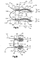
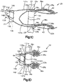
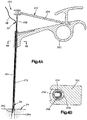
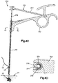
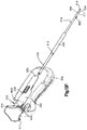
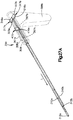
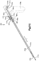
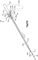
- the anchor bodies 28a and 28b of the anchors 22a and 22b can be inserted through an opening 23 at the respective target anatomical locations 24a and 24b that can be created, for example, when delivering the anchor bodies 28a and 28b to the respective target anatomical locations 24a and 24b, for instance by injecting the anchor bodies 28a and 28b to the respective target anatomical locations 24a and 24b.
- the expandable portion 36 of the anchor body 28 extends along the direction of elongation 34 so as to define an initial distance D1 as measured from the proximal end 39a to the distal end 39b along the direction of elongation 34 when in the first configuration.
- the initial distance D1 can be any length as desired, such within a range having a lower end that can be defined by approximately 5mm, alternatively approximately 10mm, alternatively still approximately 20mm, and alternatively still approximately 24.5mm, and having an upper end that can be defined by approximately 50mm, alternatively approximately 40mm, alternatively still approximately 30mm, and alternatively still approximately 25.5mm.
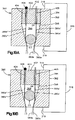
- the coupling assembly 350 releasably translatably fixes the push rod 330 to the push tube 334, such that in a second mode of operation, the coupling assembly 350 decouples the push rod 330 from the push tube 334 such that the push rod 330 can translate distally relative to the push tube 334 after the first stroke, for instance during the second stroke. Furthermore, in the second mode of operation, the coupling assembly 350 can translatably fix the push tube 334 to the casing 308, such that a distal translation force applied to the plunger 316 causes the plunger 316, and thus the push rod 330, to translate distally relative to the push tube 334, and thus the collar 332.
- the plunger 316 when the plunger 316 is rotated from the second position to the intermediate position such that the guide pin 344 travels along the intermediate track portion 342c (see Figs. 13C-D ), the first recess 354 and the channel 358 are brought into longitudinal alignment with the second recess 362.
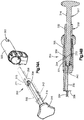
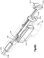
- the insertion instrument 300 can be constructed such that when the plunger 316, and thus the push rod 330, is in the first position, the first and second anchor bodies 28a and 28b are disposed in the cannula 310.
- the first anchor body 28a is disposed longitudinally between the ejection port 442 and the plug 314 of the push tube 334.
- the insertion instrument can include a depth stop 383 that extends radially out from the cannula 310, and is configured to abut the anatomical structure 24 and provides resistance to further insertion of the cannula 310 into the anatomical structure 24 once the cannula 310 has been injected to a desired depth, for instance such that the ejection port 442 is disposed behind the anatomical structure 24.
- the depth stop 383 can provide tactile feedback to the user that the cannula 310 has been injected into the target structure 24 at the desired depth.
- the distal force can be removed from the plunger 316, which causes the spring member 365 to bias the second pusher assembly 333, for instance the collar 332, and thus also the first pusher assembly 317, proximally until the guide pin 344 is aligned with the offset position 342a"' of the first track portion 342a, as described above.
- the guide pin is aligned with the intermediate track portion 342c, and the plunger 316 can be rotated to the second track portion 342b.
- the insertion instrument 300 includes a strand retention assembly 390 that retains, for instance releaseably retains, at least one tensioning strand 380 that is operably coupled to the actuation portions 131a and 131b of the first and second anchor bodies 28a and 28b, extends proximally into the interior 328 of the casing 308 and is releasably connected to the retention assembly 390.
- the insertion instrument 300 can further define an elongate side slot 315 that extends through one radial side of the cannula 310 at a location proximal with respect to the ejection port 442.
- the slot 315 can extend from the ejection port 442 and proximally a sufficient distance and sized sufficiently such that the actuation portions 131a-b and attachment portions 133 can extends through the slot 315 and attach to the tensioning strand 380, which extends proximally into the casing 308.
- the at least one tensioning strand 380 can be attached to the actuation portions 131a-b inside the cannula 310, and can extend out the slot 315.
- the plunger 316 can be rotated along the direction of Arrow A before or after the tip 311 has been injected at the first target anatomical location 24a so as to travel along the intermediate stroke, which causes the guide pin 344 to translate along the intermediate track portion 342c toward the second track portion 342b.
- the plunger 316 can be rotated along the direction of Arrow A until the plunger 316 is in the intermediate position, whereby the guide pin 344 is longitudinally aligned with the second track portion 342b.
- the plunger 316 and collar 332 Once the plunger 316 and collar 332 have rotated to the intermediate position, the plunger 316 and the collar 332 are again able to translate distally with respect to the casing 308, and the latch 370 is longitudinally aligned with the second recess 362.
- the second recess 362 can be positioned such that the latch 370 is radially aligned with the second recess 362 once the plug 314 has translated to a position distal with respect to the tip 311, and thus distal with respect to the ejection port 442, which can occur once the plunger 316 has translated along the first portion of the second stroke. Because the plug 314 has translated distal to the ejection port 442, the plug 314 is removed from interference with the first anchor body 28a as the first anchor body 28a is ejected out the cannula 310.
- the push rod 330 and the push tube 334 translate together along the first portion of the second stroke, the push rod 330 continues to bias the first anchor body 28b downstream in the elongate opening 312 of the cannula 310 toward the tip 311.
- the latch 370 is driven from the first recess 354 into the second recess 362.
- the coupling assembly 350 is configured such that the collar 332 moves along the first stroke with the plunger 316, moves along the intermediate stroke with the plunger 316, and moves along a first portion of the second stroke with the plunger 316, it should be appreciated in accordance with alternative embodiments that the coupling assembly 350 can be configured such that the collar 332 translatably decouples from the plunger 316 after or during the first stroke, or after or during the intermediate stroke.
- the first anchor body 28a can be actuated to its expanded configuration.
- the first anchor body 28a can be manually expanded by the user applying the actuation force F ( Fig. 1A ) to the respective actuation portion 131a.
- the actuation strands 38a and 38b of the first and second anchor bodies 28a and 28b, respectively can be a common strand.
- the actuation portion 131a is integral with the actuation portion 131b, and proximal translation of the insertion instrument 300, for instance upon removal of the insertion instrument 300 from the anatomical structure 24, can cause the insertion instrument 300 to apply a proximal tensile force onto the tensioning strand 380, which communicates the tensile force to the second anchor body 28b, thereby actuating the second anchor body 28 to its expanded configuration.
- the coupling assembly 350 can be constructed in accordance with another embodiment, and can include at least one first coupling member 352 illustrated as a first recess 354 that extends radially into the first pusher assembly 317, such as the plunger 316, in accordance with the illustrated embodiment.
- the coupling assembly 350 can further include at least one second coupling member 356 illustrated as a channel 358, that extends radially through the second pusher assembly 333, such as the collar 332, in accordance with the illustrated embodiment.
- the coupling assembly 350 can further include at least one third coupling member 360 illustrated as a second recess 362 ( Fig. 15C ), that extends radially outward into the casing 308 in accordance with the illustrated embodiment.
- the second recess 362 is disposed distal with respect to the channel 358 when the plunger 316 is in the first position illustrated in Figs. 7A and 13A .
- the second recess 362 can further be radially offset with respect to the channel 358 when the plunger 316 is in the first position illustrated in Figs. 7A and 13A .
- the second recess 362 can be radially aligned with respect to the second recess 362 (for instance if the track 342 does not include the intermediate track portion 342c, and can alternatively still be annular so as to circumscribe the radially inner surface of the casing 308 if desired.
- the latch 370 can be further sized to be disposed in the channel 358, which can be in the form of a slot that is defined by a longitudinal dimension substantially equal to that of the latch 370, and is further defined by a radial dimension that is substantially equal to that of the latch 370. Accordingly, the latch 370 can travel along the channel 358 between the first recess 354 ( Figs, 15A-B ) and the second recess 362 ( Figs. 15D-E ).
- the latch 370 defines a radial dimension substantially equal to that of the first recess 354 and the channel 358 combined, which is substantially equal to that of the channel 358 and the second recess 362, combined.
- the radial dimension of the latch 370 is also substantially equal to that of the channel 358 and the second recess 362 combined. It should also therefore be appreciated that the first recess 354 and the second recess 362 can define substantially the same radial dimension.
- the plunger 316 when the plunger 316 is rotated from the second position to the intermediate position such that the guide pin 344 travels along the intermediate track portion 342c (see Figs. 13C-D ), the first recess 354 and the channel 358 are brought into longitudinal alignment with the second recess 362.
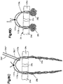
- the anchor assembly 20 can include at least one tensioning member, such as a tensioning strand 380 that can be stitched through the first and second actuation strands 38a and 38b, respectively, of the first and second anchor bodies 28a and 28b.
- the anchor assembly 20 can include as many tensioning strands as desired that extend through one or both of the first and second actuation strands 38a and 38b.
- the tensioning strand 380 defines a first end 380', a second end 380", and a middle portion 380"' that extends between the first and second ends 380' and 380".
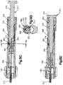
- the insertion instrument 300 can include a retention assembly, such as a strand retention assembly 390, that is configured to retain the at least one tensioning strand 380, and in particular the first and second ends 380a' and 380" of the tensioning strand 380.
- the retention assembly releasably retains the tensioning strands 380.
- the retention assembly 390 is translatably fixed to the first pusher assembly 317, and thus moves proximally and distally along the longitudinal direction L along with the plunger 316.
- the tensioning strand 308 provides sufficient slack for the implantation of the first and second anchor bodies 28a and 28b in the respective target anatomical locations 24a and 24b.
- proximal movement of the insertion instrument 300 causes the retention assembly 390 to move in the proximal direction, thereby applying the tensile actuation force to the second tensioning strand 380, which communicates the actuation force to the second actuation portion 131b of the second actuation strand 38b, and causes the second anchor body 28b to expand.
- the second locking member 402 includes a second locking body 415, and a second clip 417 that is configured to be secured to the second locking body 415.
- the retention housing 392 can define a second retention channel 419 disposed between the second locking body 415 and the second clip 417.
- the second retention channel 419 can have any suitable shape as desired, and defines a serpentine shape in accordance with the illustrated embodiment.
- the second retention channel 419 has a thickness less than that of the second end 380" of the tensioning strand 380.
- the strand retention assembly 390 can be constructed in accordance with an alternative embodiment to releasably retain the at least one tensioning strand 380.
- the strand retention assembly 390 illustrated in Figs. 19A-B are illustrated as retaining the pair of first and second tensioning strands 380a and 380b, the retention assembly 390 can alternatively releasably retain a single tensioning strand, for instance as described above with respect to Figs. 16-17 .
- the retention assembly 390 retains the first and second ends 380a' and 380" and 380b' and 380b" of the first and second tensioning strands 380a and 380b.
- the retention assembly 390 releasably retains the first and second tensioning strands 380a and 380b.
- the retention assembly 390 is translatably fixed to the first pusher assembly 317, and thus moves proximally and distally along the longitudinal direction L along with the plunger 316.
- the interior surface 398 can slope (for instance linearly, curvilinearly, or along any suitable alternative shape) radially outward as it travels proximally along a direction from a distal end of the housing body 394 to a proximal end of the housing body 394.
- the bore 396 can define a first cross-sectional dimension D3 along a direction substantially perpendicular to the longitudinal axis 302 at its first or proximal end, and a second cross-sectional dimension D4 along a direction substantially perpendicular to the longitudinal axis 302 at its second or distal end. Because the bore 396 can be tapered, the first cross-sectional dimension D3 can be less than the second cross-sectional dimension D4.
- the bore 396 can be tapered, for instance linearly, curvilinearly, or along any suitable alternatively shape as desired.
- the first locking member 400 is configured to bear against the interior surface 398 during operation of the instrument, thereby capturing the first ends 380a' and 380b' between the first locking member 400 and the interior surface 398 of the housing body 394, and preventing relative movement between each of the first ends 380a' and 380b' and the retention housing 392.
- the first locking member 400 can present a first locking surface
- the interior surface 398 can present a second locking surface that cooperates with the first locking surface so as to retain the first ends 380a' and 380b' of the first and second retention strands 380a and 380b in the retention assembly 390.
- the retention assembly 390 can further include a second locking member 402 that is configured to be attached to the first locking member 400.
- the second locking member 402 can include a threaded plug 403 that is threadedly inserted into the proximal end of the housing body 394.
- the second locking member 402 can be disposed adjacent the tapered inner surface 398, and can close the proximal end of the tapered bore 396.
- the second locking member 402 can be integral with the housing body 394.
- the second locking member 402 defines at least one opening, such as a longitudinal opening 404, that is configured to receive the end of the one or more tensioning strands that are opposite the end of the tensioning strands that are captured between the first locking member 400 and the interior surface 398 of the housing body 394. Accordingly, the second locking member 402 is configured to receive each of the second ends 380a" and 380b" of the first and second tensioning strands 380a and 380b. The second locking member 402 can thus be aligned with the tapered bore 396, such that the second end 380a" and 380b" of each of the first and second strands 380a and 380b extends through the tapered bore 396 and is attached to the second locking member 402.
- the second ends 380a" and 380b" can alternatively or additionally extend between the first locking member 400 and the interior surface 398, and can be captured between the first locking member 400 and the interior surface 398 as desired so as to retain the second ends 380a" and 380b" in the retention assembly 390.
- the second locking member 402 can further include a second longitudinal opening 405 that is spaced from the longitudinal opening 404. The second longitudinal opening 405 is configured to receive the remainder of the first ends 380a' and 380b' that are captured between the first locking member 400 and the interior surface 398.
- the first pusher assembly 317 can include a pair of flanges 319 that project out from the plunger 316 so as to define a gap 321 that extends between the flanges 319.
- the gap 321 can be sized to receive the housing body 394, such that each of the flanges 319 abuts the proximal and distal ends of the housing body 394, respectively. Accordingly, proximal movement of the plunger 316 causes the distal one of the flanges 319 to bias the housing body 394 and thus the retention assembly 390, to move proximally along with the plunger 316,and therefore also along with the push rod 330.
- the insertion instrument 300 can be translated proximally as it is removed from the anatomical tissue 24 as described above.
- the retention assembly 390 applies a tensile force to the tensioning strand 380b, which is communicated to the second actuation strand 38b as the actuation force that causes the second anchor body 28b to move from the first configuration illustrated in Fig. 9A to the expanded configuration illustrated in Fig. 9E .
- the retention assembly 390 applies a tensile force to the first tensioning strand 380a, which is communicated to the first actuation strand 38a as the actuation force that causes the first anchor body 28a to move from the first configuration illustrated in Fig. 12A to the expanded configuration illustrated in Fig. 12E .
- the tensioning strands 380a and 380b can be released from the retention assembly 390.
- the retention assembly 390 can configured to release at one of the ends of the tensioning strands 380a and 380b.
- the insertion instrument 300 can include a cutting blade that is configured to sever the first and second tensioning strands 380a and 380b.
- the insertion instrument 300 can include a release member 408 that is coupled to the retention assembly 390 and is configured to iterate the retention assembly 390 to an unlocked configuration.
- the release member 480 can include any suitable linkage 410 that can be aligned with the first locking member 400.
- the release member 408 can include an actuator 414 that is carried by the casing 308 and coupled to the linkage 410, such that a user can manipulate the actuator 414, for instance slide the actuator proximally, so as to cause the linkage 410 to contact the first locking member 400 and bias the first locking member 400 proximally along the direction of Arrow 401 to an unlocked configuration, which creates a gap 412 between the first locking member 400 and the interior surface 398, as illustrated in Fig. 19B .
- the gap can be greater than a cross-sectional dimension of the tensioning strands 380a and 380b.
- the retention assembly 390 can be attached to a single tensioning strand, such that the cutting blade 418 is configured to cut a first end of the single tensioning strand, such that removal of the insertion instrument 300 from the anchor bodies 28a and 28b draws the tensioning strand through and away from actuation strands 38a and 38b.
- the cutting assembly 416 can include a longitudinally elongate shaft 420, and a switch 422 that is pivotally coupled between the elongate shaft 420 and the cutting blade 418, thereby coupling the elongate shaft 420 to the cutting blade 418.
- the cutting blade 418 can be carried by a blade housing 424, such that the elongate shaft 420 and the switch 422 are indirectly coupled to the cutting blade 418.
- the proximal end of the longitudinally elongate shaft 420 can extend proximally out of the casing 408, and the longitudinal shaft can extend in a side wall of the casing 408.
- the shaft 420 is movable longitudinally in the distal direction from a disengaged position to an engaged position.
- Distal movement of the shaft 420 causes the switch to pivot, thereby driving the cutting blade 418 to translate proximally and into the first ends 380a' and 380b' of the first and second tensioning strands 380a and 380b, thereby severing the first ends 380a' and 380b'.
- the instrument can be translated proximally with respect to the ejected anchor bodies 28a and 28b so as to remove the tensioning strands 380a and 380b from the respective actuation strands 38a and 38b in the manner described above.
- the cutting assembly 416 can be constructed in accordance with any alternative embodiment as desired.
- the cutting assembly 416 can include an actuator 426 that extends laterally out the side wall of the casing 408 along a direction angularly offset with respect to the longitudinal direction L, and is movable radially inward from the disengaged position to the engaged position.
- the actuator 426 can carry the cutting blade 418. Accordingly, as the actuator 426 moves radially inward, the cutting blade 418 severs the first and second ends 380a' and 380b' of the actuation strands 380a and 380b.
- the plunger 316 and collar 332 can be translated distally from the first position to the second position in tandem along the first stroke in the manner described above.
- the guide pin 344 translates proximally within the entire guide track 342.
- the plunger 316 and collar 332 reach the second position when the clip 434 abuts the casing 308, at which point the latch member 370 moves from the first recess 354 into the second recess 358 as described above with respect to Figs. 14C-D .
- the clip 434 can be removed from the plunger 316, and the plunger 316 can translate distally with respect to the collar 332 along the second stroke. It should be appreciated that the plunger 316 can translate along the entire second stroke independent of the collar 332.
- the push tube 334 ejects the second anchor body 38b as described above with respect to Figs. 9A-E after the plunger and collar 332 have moved along the first stroke from the first position to the second position.
- the plunger 316 can be depressed a first distance that causes the second anchor body 28b to be ejected from the insertion instrument, and the clip 434 abuts the casing 308 once the plunger 316 has been depressed the first distance so as to prevent the plunger 316 from being depressed a second distance greater than the first distance until the collar 434 is removed from the plunger 316.
- the shaft portion 430 of the plunger 316 defines a distal surface 431, and further defines a first central aperture 440 that extends longitudinally into, or distally into, the distal surface 431.
- the shaft portion 430 of the plunger 316 further defines a radial aperture 435 that receives the guide pin 448.
- the first aperture 440 receives the push rod 330, such that the plunger 316 and the push rod 330 are coupled to each other with respect to both longitudinal translation and rotation.
- the push rod 330 extends from the plunger 316 and into the cannula 310, which is fixed to the casing 308 with respect to translation and rotation. Referring also to Fig.
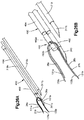
- the tip 311 can be cannulated so as to define a distal ejection port 442 that is substantially aligned with the longitudinal axis 302, and thus also substantially aligned with the elongate opening 312 of the cannula 310.
- the push rod 330 is movable longitudinally inside the channel 312 in the manner described above.
- the insertion instrument 300 can alternatively define a side ejection port constructed substantially as described below.
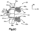
- the cannula 310 can define a longitudinal slot 337, such that the attachment portions 133a and 133b of the actuation strands 38a and 38b (see Fig. 1A ) that attach the first anchor body 28a to the second anchor body 28b can extend out the slot 337.
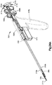
- the insertion instrument includes a guide system 444 that is configured to operably couple the casing 308 to the push rod 330 so as to guide relative movement between the casing 308 and the push rod 330.
- the guide system 444 includes the first guide member in the form of the first guide track 446 that is carried by the casing 308, and the second guide member illustrated as the first guide pin 448 that extends from the pusher assembly 317.
- the first guide track 446 can be configured as a slot that extends radially outward into the radially inner surface of the casing 308.
- the first track portions 446a and 450a define a first stroke of movement for the plunger 316 that causes the push rod 330 to eject the second anchor out the ejection port 442.
- the intermediate track portions 446ba and 450b are configured such that the plunger is rotated so as to align a fifth guide member with a second track portion that is radially offset from the first track portions 446a and 450a.
- the insertion instrument 330 further includes a pair of apertures 452 that arc disposed adjacent the central aperture 440 and extend longitudinally into the distal surface 431 of the shaft portion 430 of the plunger 416.
- the apertures 452 are each configured to receive respective fifth guide members configured as guide posts 454 ( Fig.
- a distal biasing force can be applied to the plunger 316, which causes the plunger 316 and the push rod 330 to translate distally along the first stroke with respect to the casing 308 and thus the cannula 310 and the guide housing 460.
- the plunger 316 translates from the first position illustrated in Fig. 23A to the second position illustrated in Fig. 23F .
- the first guide pin 448 translates distally along the first track portion 446a of the first guide track 446 until the first guide pin 448 is aligned with the intermediate track portion 446b of the first guide track 446.
- the second guide pin 461 translates distally in the first track portion 450a of the second guide track 450 until the second guide pin 461 is aligned with the intermediate track portion 450b of the second guide track 450.
- the guide posts 454 are circumferentially offset from the respective second track portions 462, and abut the guide housing 460, for instance in the recesses 464.
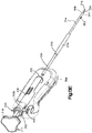
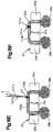
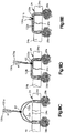
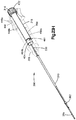
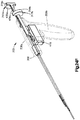
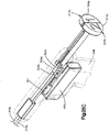
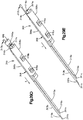
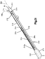
- an insertion instrument can be configured having a first and second cannulas supported by the casing in a side-by-side orientation that retain first and second anchor bodies, and first and second pusher assemblies operatively associated with the first and second cannulas, respectively, so as to eject the first and second anchor bodies out the respective first and second cannulas. It can be desirable to ensure that a desired cannula from which the anchor body is to be ejected is distally disposed with respect to the other cannula, such that the desired cannula can be inserted into the underlying tissue without also inserting the other cannula.
- the insertion instrument 300 can further include first and second pusher assemblies 317a and 317b operatively associated with the first and second cannulas 310a and 310b, respectively.
- first pusher assembly 317a is configured to eject the first anchor body 28a out the first cannula 310a
- the second pusher assembly 317b is configured to eject the second anchor body 28b out the second cannula 310b.
- the first and second cannulas 310a and 310b can define respective first and second tapered tips 311a and 311b, and first and second distal ejection ports that extend longitudinally through the respective tips 311a and 311b.
- the insertion instrument 300 can further include first and second lock-out tabs 468a and 468b that are removably attached to the first and second plungers 316a and 316b.
- first and second lock-out tabs 468a and 468b are attached to the respective first and second shaft portions 430a and 430b at a location longitudinally between the corresponding grip portions 432a and 432b and the casing 308. Accordingly, the first and second lock-out tabs 468a and 468b interfere with the respective grip portions 432a and 432b, and prevent the plungers 316 from translating distally relative to the casing 308 to a depth that would eject the respective first and second anchor bodies 28a and 28b.
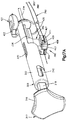
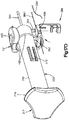
- the insertion instrument 330 can further include a swap actuator 470 in the form of a trigger that extends partially into the casing 308, and can extend out from the handle portion 308b.
- the swap actuator 470 is configured to be moved from a first position to an actuated position so as to reverse a relative position of the fist and second tips 311a and 311b.
- the swap actuator 470 can be coupled to the first pusher assembly 317a, such that proximal translation of the actuator 470 causes the first pusher assembly 317a, including the first plunger 316a and the first cannula 310a, to translate proximally. As illustrated in Fig.
- the second lock-out tab 468b can be removed from the second plunger 316b, as illustrated in Fig. 24D .
- the swap actuator 470 can be actuated, for instance can be moved proximally, to retract the first tip 311a proximally with respect to the second cannula 310b until the first tip 311a is disposed proximally with respect to the second tip 311b.
- the distal end of the first push rod 330a can extend slightly out from the respective first tip 311a, such that the longitudinal distance between the distal end of the first push rod 330a and the distal end of the second tip 311b defines an insertion depth of the second tip 311 b into the underlying anatomical structure. Otherwise stated, the first push rod 330a can define a depth stop for insertion of the second tip 311a into underlying tissue. It should thus be appreciated that the second tip 311b can be injected into underlying tissue, for instance at the second target anatomical location 24b (see Fig. 1A ) without causing the first tip 311a to inject into the underlying tissue. In accordance with the illustrated embodiment, actuation of the swap actuator 470 further causes the first plunger 316a to translate proximally to the first position illustrated in Fig. 24A .
- the second plunger 316b can travel distally with respect to the casing 308 from the first position illustrated in Fig. 24E to a second position as illustrated in Fig. 24F whereby the second grip portion 432b abuts the casing 308. Because the second push rod 330b is translatably fixed to the second plunger 316b, distal translation of the second plunger 316b causes the second push rod 330b to likewise translate in the second cannula 310b, thereby ejecting the second anchor body 28b out the second ejection port 442b and into the second target anatomical location.
- the insertion instrument 300 includes at least one latch assembly such as a first latch assembly 305a, a second latch assembly 305b, and a third latch assembly 305c.
- the first latch assembly 305a is configured to lock the swap actuator 470 in its proximal position once it has been moved proximally from a first position illustrated in Fig. 24D to a second recessed position illustrated in Fig. 24E .
- the first latch assembly 305 can include a latch member 307 that is supported by the casing 308 extends proximally toward a proximal abutment surface 307a configured to abut the swap actuator 470 once the swap actuator 470 is in its second proximal position, thereby interfering with distal movement of the swap actuator 470 relative to the casing 308.
- the latch member 307 can deflect inwardly away from the swap actuator 470 so as to allow proximal translation of the swap member 470 relative to the latch member 307.
- the latch member 307 moves outward under its spring force such that the proximal abutment surface 307a abuts the swap actuator 470 and prevents the swap actuator 407 from moving distally from its second position with respect to the casing 308.
- the second latch assembly 305b includes a first latch member 347 carried by the swap actuator 470 and movable with the swap actuator 470, and a second latch member 349 that is carried by the first plunger 316a, and is movable with the first plunger 316a.
- the first latch member 347 is attached to the first cannula 310a, such that the first latch member 347 causes the first cannula 310a to translate with the swap actuator 470.
- the second latch member 349 includes a body 349a, a first attachment portion such as a hook at the distal end of the body 349a, and a second attachment portion such as an abutment surface at the proximal end of the body (the second latch member 349 can be constructed as the mirror image of the second latch member 353 of the third latch assembly 305c described below). Accordingly, as the first plunger 316a is translated from its first position illustrated in Fig. 24A to its second position illustrated in Fig. 24B , the hook deflects inwardly away from the first latch member and rides along and past the first latch member 347. Once the first plunger 316a is in its second position illustrated in Fig.
- the hook of the second latch member 349 moves outward under its spring force such that the hook is disposed distal of the first latch member 347, and the abutment surface of the second latch member is disposed proximal of the first latch member 347. Accordingly, the first latch member 347 is captured between the hook of the second latch member 349 and the abutment surface of the second latch member 349. Thus, the first and second latch members 349 are coupled with respect to translation.
- the second latch member 349 is attached to the first latch member 347, which translatably couples the first plunger 316a to the swap actuator 470 with respect to translation. Furthermore, because the first latch member 347 is carried by the swap actuator 470 and is further attached to the first cannula 310a, movement of the swap actuator 470 proximally causes both the first cannula 310a and the first plunger 316 to move proximally to a position whereby the first tip 311a and the first push rod 330a are disposed proximal with respect to the second tip 311b, while the first push rod 330a remains disposed distal of the first tip 311a.
- the hook can deflect inwardly, away from the first latch member 351 and ride along and move past the first latch member 351.
- the hook of the second latch member 353 moves outwardly under its spring force at a location distal of the first latch member 351, and the abutment surface of the second latch member 353 is disposed proximal of the first latch member 351.
- the first latch member 351 is thus captured between the hook of the second latch member 353 and the abutment surface of the second latch member 353.
- the second plunger 316b is prevented from moving proximally or distally with respect to the casing 308 once the second anchor body 28b has been ejected, and the blunt distal end of the second push rod 330b remains distal to the second tip 311b.
- first and second tensioning strands 380a and 380b can be attached between the respective actuation portions 131a and 131b, and the respective lock-out tabs 468a and 468b.
- proximal movement of the lock-out tabs 468a and 468b with respect to the anchor bodies 28a and 28b causes the tensile force to be applied to the corresponding tensioning strands 380a and 380b, which communicates the tensile force to the actuation portions 131a and 131b so as to expand the anchor bodies 28a and 28b.
- the tensioning strands 380a and 380b can be secured in the casing 308 in any manner described above.
- the insertion instrument 300 can include a retention assembly 490 constructed in accordance with an alternative embodiment that is configured to apply an actuation force to the first and second actuation strands 38a and 38b (see Fig. 1A ).
- the retention assembly 490 can retain the first and second actuation strands 38a and 38b directly.
- the retention assembly 490 retains both the actuation portions 131a and 131b and the attachment portions 133a and 133b of the first and second anchor bodies 28a and 28b, respectively, for instance when the attachment portions 133a and 133b are not attached when loaded in the insertion instrument 300.
- the retention assembly can retain only the actuation portions 131a and 131b.
- at least one tensioning strand can be stitched through the first and second actuation strands 38 and 38b, respectively, and can further be retained in the retention assembly 490.
- the retention assembly can be configured to apply an actuation force to the actuation strands 38a and 38b that causes the respective anchor bodies 28a and 28b to move to their expanded configurations.
- the retention assembly 490 can be mounted to either or both of the cannulas, such as the first cannula 310a as shown in Fig. 26A .
- the retention assembly 490 can include a first locking member such as a retention housing 492 that is mounted to the first cannula 310a and defines a lateral strand-receiving gap 493 extending therein.
- the retention housing includes a first or proximal housing portion 492a and a second or distal housing portion 492b, such that the gap 493 is disposed between the first and second housing portions 492a and 492b.
- one or more target strands 379 such as the actuation strand or strands 38a and 38b or at least one tensioning strand can be loaded into the gap 493, and the pincher 494 can be rotated in the first direction until the retention assembly 490 captures the target strands 379 between a distal end of the pincher 494 and the second housing portion 492b.
- the cannulas 310a and 310b can define longitudinal slots that extend through one side of the cannulas 310a and 310b, the actuation strands 38a and 38b can be freed from the respective cannula, for instance out the longitudinal slot, when the corresponding anchor bodies 28a and 28b are ejected from the cannula.
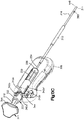
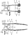
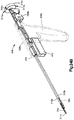
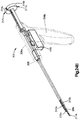
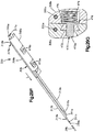
- the insertion instrument 300 can be configured having a first and second cannulas 310a and 310b supported by the casing 308 in a side-by-side orientation that retain first and second anchor bodies 28a and 28b, and first and second pusher assemblies 317a and 317b operatively associated with the first and second cannulas 310a and 310b, respectively, so as to eject the first and second anchor bodies 28a and 28b out the respective first and second cannulas 310a and 310b.
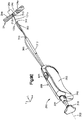
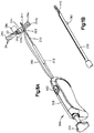
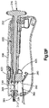
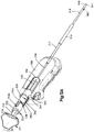
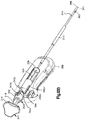
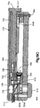
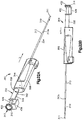
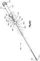
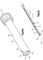
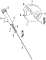
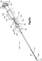
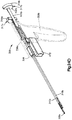
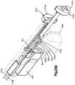
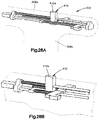
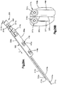
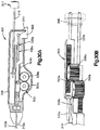
- the insertion instrument 300 includes a casing 308 that includes a body portion 308a and a handle portion 308b that extends out from the body portion 308a.
- the insertion instrument 300 further includes a first cannula 310a that extends distally from the casing 308, and in particular from the body portion 308a, and a second cannula 310b that extends distally from the casing 308, and in particular from the body portion 308a, at a location adjacent the first cannula 310a.
- the first and second cannulas 310a and 310b can extend substantially parallel to each other as illustrated.
- the insertion instrument 300 can further include first and second pusher assemblies 317a and 317b operatively associated with the first and second cannulas 310a and 310b, respectively.
- first pusher assembly 317a is configured to eject the first anchor body 28a out the first cannula 310a
- the second pusher assembly 317b is configured to eject the second anchor body 28b out the second cannula 310b.
- the first and second cannulas 310a and 310b can define respective first and second tapered tips 311a and 311b, and first and second distal ejection ports 442a and 442b that extend longitudinally through the respective tips 311a and 311b.
- Each of the first and second pusher assemblies 317a and 317b includes first and second plungers 316a and 316b, respectively, that extends out the casing 308, such as the body portion 308a of the casing 308.
- the first and second plungers 316a and 316b can extend proximally out the casing 308 as described above with respect to Figs. 24A-F , or can extend out the casing along a direction angularly offset with respect to the longitudinal direction L so as to present respective tabs 323a and 323b that project out the casing 308.
- Each of the first and second pusher assemblies 317a and 317b can further include first and second pusher rods 330a and 330b, respectively, that extend distally from the corresponding plungers 316a and 316b.
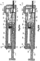
- first and second plungers 316a and 316b are in their respective first positions ( Fig. 27A )
- the first and second anchor bodies 28a and 28b are disposed in the respective cannulas 310a and 310b.
- the plungers 316a and 316b can be moved to respective second positions ( Fig. 27D ) so as to eject the respective first and second anchor bodies 28a and 28b out the respective cannulas 310a and 310b.
- the slots 367a-c can thus provide tracks that define the longitudinal movement of the first and second pusher assemblies 317a and 317b and the swap actuator 470 as the tabs 323a-b and 470a ride in the respective slots 367a-c.
- the swap actuator 470 is configured to be moved from a first position to an actuated position so as to reverse a relative position of the fist and second tips 311a and 311 b. For instance, as illustrated in Fig. 27A , the first tip 311a of the first cannula 310a is disposed distally with respect to the second tip 311b of the second cannula 310b.
- the first tip 311a can be injected into underlying tissue, for instance at the first target anatomical location 24a (see Fig. 1A ) without causing the second tip 311b to inject into the underlying tissue.
- actuation of the swap actuator 470 from a first position ( Fig. 27A ) to a second position along the direction of Arrow 355 ( Fig. 27C ) causes the second tip 311b to move distally with respect to the first tip 311a, such that the second tip 311b can be injected into the underlying tissue, for instance at the second target anatomical location 24b (see Fig. 1B ) without causing the first tip 311a to inject into the underlying tissue.
- the first plunger 316a can be translated distally along the direction of Arrow 357 from the first position to the second position, which causes the first push rod 330a to likewise translate distally in the first cannula 310a.
- the first push rod 330a abuts the first anchor body 28a, such that the first push rod 330a ejects the first anchor body 28a out the first cannula 310a, for instance into the first target anatomical location, as the first push rod 300a translates distally to the second position.
- the second plunger 316b can be translated distally along the direction of Arrow 359 from the first position to the second position, which causes the second push rod 330b to likewise translate distally in the second cannula 310b.
- the second push rod 330b abuts the second anchor body 28b, such that the second push rod 330b ejects the second anchor body 28b out the second cannula 330b, for instance into the second target anatomical location, as the second push rod 300b translates distally to the second position.
- the insertion instrument 300 includes at least one latch assembly such as a first latch assembly 482, a second latch assembly 484, and a third latch assembly 486.
- the first latch assembly 482 is configured to lock the swap actuator 470 in its distal position once it has been moved distally from a first position illustrated in Fig. 27B to a second recessed position illustrated in Fig. 27C .
- the first latch assembly 482 can include a latch member 488 that is supported by the casing 308 and configured to latch onto the swap actuator 470 so as to be coupled to the swap actuator 470 with respect to translation.
- the swap actuator 470 contacts the abutment surface and the hook can deflect outward under the spring force of the body 488a, such that the swap actuator 470, for instance the tab 470a, becomes captured between the first and second attachment portions 488b and 488c. Accordingly, the latch member 488 prevents the swap actuator 470 from moving proximally and distally relative to the casing once the swap actuator 470 has been moved to its proximal position that advances the second pusher assembly 317b distally with respect to the first pusher assembly 316a.
- the insertion instrument 300 can further include at least one first guide member 483a such as a guide wire that is translatably fixed to the casing 308.
- the insertion instrument 300 can include a mount 485 that is supported by the casing 308 and is attached to the first guide member 483a.
- the first guide member 483 can extend through the swap actuator 470 so as to guide the swap actuator to translate distally.
- the second latch assembly 484 is configured to lock the first plunger 316a, and thus the first pusher assembly 317a, in its proximal position proximal position once it has been moved distally from a first position illustrated in Fig. 27A to a second distal position illustrated in Fig. 27B that causes the first push rod 330a to eject the first anchor body 28a.
- the second latch assembly 484 can include a latch member 489 that is supported by the casing 308 and configured to latch onto the first plunger 316a so as to be coupled to the first plunger 316a with respect to translation.
- the second latch member 489 can be constructed substantially identically with respect to the first latch member 488, and thus defines a body, a first attachment portion in the form of a hook carried by the body, and a second attachment portion in the form of an abutment surface carried by the body and disposed distal of the hook.
- the first attachment portion can deflect inwardly away from the first plunger 316a so as to allow distal translation of the first plunger 316a relative to the second latch member 489, such as an outwardly projecting tab 316c of the first plunger 316a.
- the first plunger 316a contacts the abutment surface and the hook can deflect outward under the spring force of the body of the latch member 489, such that the first plunger 316a, for instance the tab 316c, becomes captured between the first and second attachment portions of the latch member 489. Accordingly, the latch member 489 prevents the first plunger 316a from moving proximally and distally relative to the casing 308 once the first plunger 316 has been moved to its distal position that ejects the first anchor body 28a from the first cannula 310a.
- the third latch assembly 486 is configured to lock the second plunger 316b, and thus the second pusher assembly 317b, in its distal position proximal position once it has been moved distally from a first position illustrated in Fig. 27C to a second distal position illustrated in Fig. 27D that causes the second push rod 330b to eject the second anchor body 28b.
- the third latch assembly 486 can include a third latch member 495 that is supported by the casing 308 and configured to latch onto the second plunger 316b so as to be coupled to the second plunger 316b with respect to translation.
- the second plunger 316b Once the second plunger 316b has been moved from its first initial position to its second proximal position relative to the casing 308, the second plunger 316b, for instance at the tab 316d, contacts the abutment surface 495c and the hook 495b can deflect outward under the spring force of the latch member body 495a, such that the second plunger 316b becomes captured between the first and second attachment portions of the latch member 495. Accordingly, the latch member 495 prevents the second plunger 316b from moving proximally and distally relative to the casing 308 once the second plunger 316b has been moved to its distal position that ejects the second anchor body 28b from the second cannula 310b.
- the insertion instrument 300 can further include at least one third guide member 483c such as a guide wire that is translatably fixed to the casing 308.
- the mount 485 can be attached to the third guide member 483c, which can extend distally through the second plunger 316b so as to guide the second plunger 316b to translate distally.
- the insertion instrument 300 can include an attachment member 496 in the form of an attachment wire that attaches the second plunger 316b to the swap actuator 470 with respect to distal translation of the swap actuator 470. For instance, distal translation of the swap actuator 470 causes the second plunger 316b to translate distally along with the swap actuator 470.
- a distal force applied to the second plunger 316b can allow the second plunger 316b to translate distally relative to the swap actuator 470.
- the attachment member 496 can be translatably fixed to the swap actuator 470, and can be attached to the second plunger 316b so that it interferes with the second plunger 316 with respect to proximal movement 316b of the second plunger 316b relative to the attachment member 493.
- the swap actuator 470 can include a second tab 470b that is attached to the second cannula 310b with respect to translation, such that distal translation of the swap actuator 470 causes the second cannula 310b to translate distally along with the swap actuator 470.
- distal translation of the swap actuator 470 causes the attachment member 496 to drag the second plunger 316b, the second cannula 310b, and the second push rod 330b distally until the second tip 311b is disposed distal of the first tip 311a. Because the first pusher rod 330a remains disposed distal of the first tip 311a after the first anchor body 28a has been ejected, the distal end of the first pusher rod 330a can define an insertion depth stop for the second tip 311b in the manner described above.
- the attachment member 496 can extend at least partially through the second plunger 496b so as to allow the second plunger 496b to translate distally with respect to the attachment member 496 and therefore also with respect to the swap actuator 470.
- the swap actuator 470 has been translated distally, thereby also translating the second cannula 310b and the second pusher assembly 317b distally, translation of the second plunger 316b causes the second push rod 330b to eject the second anchor body 28b from the second cannula 310b in the manner described above.
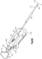
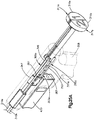
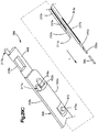
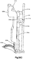
- the insertion instrument 300 can be configured having a first and second cannulas 310a and 310b supported by the casing 308 in a side-by-side orientation that retain first and second anchor bodies 28a and 28b, and first and second pusher assemblies 317a and 317b operatively associated with the first and second cannulas 310a and 310b, respectively, so as to eject the first and second anchor bodies 28a and 28b out the respective first and second cannulas 310a and 310b.
- the insertion instrument 300 includes a casing 308 that includes a first casing portion 308a and a second casing portion 308b that is disposed adjacent the first casing portion 308b.
- the insertion instrument 300 further includes a first cannula 310a that extends distally from the first casing portion 308a, and a second cannula 310b that extends distally from the second casing portion 308b.
- the first and second casing portions 308a and 308b can extend substantially parallel to each other as illustrated. Accordingly, the first and second cannulas 310a and 310b can be described as being in a side-by-side relationship.
- the first and second cannulas 310a and 310b can define respective longitudinally elongate channels that retain respective first and second anchor bodies 28a and 28b in the manner described above.
- the first and second cannulas 310a and 310b can further include longitudinally elongate side slots 337a and 337b, respectively, that extend into one side of the cannulas and are in communication with the respective elongate channels. Accordingly, the attachment portions 133a-b of the actuation strands 38a and 38b can extend out the respective side slots 337a and 337b and attach to each other (see Fig. 1A ) when the first and second anchor bodies 28a and 28b are loaded in the respective first and second cannulas 310a and 310b.
- Each of the first and second pusher assemblies 317a and 317b includes first and second plungers 316a and 316b, respectively, that are disposed outside the respective first and second casing portions 308a and 308b at a location proximal with respect to the casing portions 308a and 308b as illustrated.
- Each of the first and second pusher assemblies 317a and 317b can further include first and second pusher rods 330a and 330b, respectively, that extend distally from the corresponding plungers 316a and 316b, through the respective first and second casing portions 308a and 308b, and into the respective first and second cannulas 310a and 310b.
- first and second plungers 316a and 316b When the first and second plungers 316a and 316b are in their respective first positions ( Fig. 29A ), the first and second anchor bodies 28a and 28b are disposed in the respective cannulas 310a and 310b.
- the plungers 316a and 316b can be moved to respective second positions ( Fig. 29F ) so as to eject the respective first and second anchor bodies 28a and 28b out the respective cannulas 310a and 310b.
- the insertion instrument 330 can further include a swap actuator 470 that can include a swap button 470a that extends laterally through the first casing portion 308a and into the second casing portion 308b.
- the swap actuator 470 is configured to selectively couple and decouple the first and second casing portions with respect to relative translation in the longitudinal direction L.
- the first and second casing portions 308a and 308b can be slidably coupled along the longitudinal direction.
- one of the casing portions, such as the first casing portion 308a can define a slot 375 extending along at least a portion of its longitudinal length.
- the other casing portion such as the second casing portion 308b
- the slot 375 and the projection 377 can flare angularly outward in a dovetail arrangement such that the first and second casing portions 308a and 308b are prevented from separating along a direction angularly offset from the longitudinal direction L.
- the swap actuator 470 is configured to move the first and second casing portions 308a and 308b relative to each other along the longitudinal direction such that the respective tips 311a and 311b move from a first relative position to a second relative position that is opposite the first relative position.
- the first tip 311a of the first cannula 310a can be initially disposed distally with respect to the second tip 311b of the second cannula 310b. It should thus be appreciated that the first tip 311a can be injected into underlying tissue, for instance at the first target anatomical location 24a (see Fig. 1A ) without causing the second tip 311b to inject into the underlying tissue. As is described in more detail below, actuation of the swap actuator 470 from a first position ( Fig.
- the second tip 311b to move distally with respect to the first tip 311 a such that the second tip 311b is positioned distal of the first tip 311a. Accordingly, the second tip 311b can be injected into the underlying tissue, for instance at the second target anatomical location 24b (see Fig. 1B ) without causing the first tip 311a to inject into the underlying tissue.
- the first plunger 316a can be translated distally from the first position to the second position, which causes the first push rod 330a to likewise translate distally in the first cannula 310a.
- the first push rod 330a abuts the first anchor body 28a, such that the first push rod 330a ejects the first anchor body 28a out the first cannula 310a, for instance into the first target anatomical location, as the first push rod 300a translates distally to the second position.
- the first plunger 316a can abuts the first casing portion 308a when the first pusher assembly 317a is in the second position, whereby the first anchor body 28a has been ejected.
- the first plunger 316a is prevented from further distal translation.
- the user is provided with tactile feedback that the first anchor body 28a has been ejected.
- the swap actuator 470 can be actuated so as to reverse the relative position of the first and second tips 311a and 311b in the manner described above.
- the swap actuator 470 can include a button 472 that extends laterally through the first casing portion 308a and into the second casing portion 308a.
- the second casing portion 308b can include a spring member 474 that biases the button 472 outward toward its first position.
- the button 472 can include at least one flange 476 that abuts a wall of the second casing portion 308b so as to prevent the force of the spring member 474 from ejecting the button 472 out the first casing portion 308a.
- the first casing portion 308a can include a pair of apertures 478a-b sized to receive the button 472 such that the button 472 extends out the first casing portion 308a.
- the first aperture 478a is disposed proximal with respect to the second aperture 478b.
- the button 472 extends through the first aperture 478a
- the first tip 311a is disposed distal with respect to the second tip 311b.
- interference between the button 472 and the first casing portion 308a prevents the first casing portion 308a from translating longitudinally relative to the second casing portion 308b.
- the button 472 When the button 472 is depressed into the slot 375, and thus into the projection 377, interference between the button 472 and the first casing portion 308a is removed, such that the first and second casing portions 308a and 308b are configured to translate longitudinally relative to each other.
- the second casing portion 308b, and thus the second cannula 310b can slide distally with respect to the first casing portion 308a, and thus the first cannula 310a, until the button 472 is driven through the second aperture 478b as illustrated in Fig. 29D .
- the second tip 311b When the button 472 extends through the second aperture 478b, the second tip 311b is disposed distal with respect to the first tip 311a. It should thus be appreciated that the second tip 311b can be injected into underlying tissue, for instance at the second target anatomical location 24b (see Fig. 1A ) without causing the first tip 311a to inject into the underlying tissue.
- the insertion instrument 300 can further include a lock-out tab 468 that is removably attached to the second push rod 330b at a location longitudinally between the corresponding plunger 316b and the second casing portion 308b. Accordingly, the lock-out tab 468 interferes with the distal translation of the plunger 316b relative to the second casing portion 308b to a depth that would eject the respective second anchor body 28b.
- the lock-out tab 468 can remain attached to the second push rod 330b until the first anchor body 28a has been ejected and the swap actuator 470 has been actuated.
- the insertion instrument 300 can further include a lock-out tab operatively associated with the first pusher assembly 317 in the manner described with respect to the second pusher assembly 317b.
- the grip portion 432b of the second plunger 416b abuts the casing 308 at the distal end after the second anchor body 28b has been ejected, thereby providing the user with tactile feedback that the second anchor body 28b has been ejected.
- the insertion instrument 300 can be configured having a first and second cannulas 310a and 310b supported by the casing 308 in a side-by-side orientation that retain first and second anchor bodies, respectively.
- Each of the first and second cannulas 310a and 310b is supported by the casing 308 so as to be translatably movable with respect to the casing 308.
- the insertion instrument 300 further includes a reciprocal motion assembly 500 that is configured to drive the first and second cannulas 310a and 310b in opposite directions.
- the reciprocal motion assembly 500 drives the second cannula 310b proximally with respect to the casing 308.
- the reciprocal motion assembly 500 drives the second cannula 310b distally with respect to the casing 308.
- the reciprocal motion assembly 500 drives the first cannula 310a proximally with respect to the casing 308.
- the reciprocal motion assembly 500 drives the first cannula 310a distally with respect to the casing 308.
- the insertion instrument 300 can include a pusher assembly 317 having a plunger 316 and first and second pusher members 330a and 330b.
- the first pusher member 330a extends into the first cannula 330a and is configured to eject a first anchor body out the first cannula 330a in the manner described above.
- the second pusher member 330b extends into the second cannula 330b and is configured to eject a second anchor body 28b out the second cannula 330b in the manner described above.
- the insertion instrument further can include a selective plunger engagement assembly 502 that is operable so as to selectively engage the plunger between one of the first and second push rods 330a and 330b.
- the plunger 316 can be translatably coupled to the first push rod 330a, such that distal translation of the plunger 316 causes the push rod 330a to translate distally and eject the first anchor body 28a out of the respective first cannula 330a.
- the plunger 316 can be translatably coupled to the second push rod 330b, such that distal translation of the plunger 316 causes the push rod 330b to translate distally and eject the second anchor body 28b out of the respective first cannula 330b.
- the reciprocal motion assembly 500 includes a first force transfer member, such as a toothed first rack 504a that is attached to the first cannula 310a and is translatably fixed to the first cannula 310a.
- the first rack 504a can be integral with the first cannula 310a or discretely attached to the first cannula 310a as desired.
- the first rack 504a extends proximally from the first cannula 310a.
- the reciprocal motion assembly 500 can further include a second force transfer member such as a second toothed rack 504b that is attached to the second cannula 310b and is translatably fixed to the second cannula 310b.
- the second rack 504b can be integral with the second cannula 310b or discretely attached to the second cannula 310b as desired. In accordance with the illustrated embodiment, the second rack 504b extends proximally from the second cannula 310b.
- the reciprocal motion assembly 500 can further include a third force transfer member such as a first gear 506a, which can be a spur gear, that mates with the first rack such that rotation of the first gear 506a drives the first rack 504a to translate substantially linearly, for instance proximally or distally.
- the first cannula 310a translates along with the first rack 504a.
- the reciprocal motion assembly 500 can further include a fourth force transfer member such as a second gear 506b, which can be a spur gear, that mates with the second rack 504b such that rotation of the second gear 506b drives the first rack 504a to translate substantially linearly, for instance proximally or distally.
- the second cannula 310b translates along with the second rack 504b.
- the second rack 504b can include a handle 508b that extends out the casing 308.
- the handle 508b can be driven distally, which causes the second cannula 310b and the second rack 504b to translate distally, thereby rotating the second gear 506b along a direction of rotation.
- the second gear 506b drives the first gear 506a to rotate along an opposite direction of rotation, which causes the first cannula 310a to translate proximally toward the casing 308.
- the reciprocal motion assembly drives the first cannula 310 in an opposite direction, such as proximally as illustrated.
- the handle 508b can include a hook 510 that latches onto the casing 308 so as to provide a safety catch that prevents distal translation of the handle 508, and thus also distal translation of the second rack 504b.
- the hook 510 can be configured to latch onto the casing 308 when the second cannula 310b is retracted, and the first cannula 310a is extended and disposed distal with respect to the second cannula 310b.
- the selective plunger engagement assembly 502 includes a track 512 carried by the casing 308.
- the track 512 can extend radially outward into an inner wall of the casing 308.
- the track includes a first portion 512a that extends substantially longitudinally and parallel to the cannulas 310a and 310b and the push rods 330a and 330b.
- the track further includes a second portion 512b that extends from the first portion 512a, for instance from the proximal end of the first portion 512a, and extends proximally and outward, such as laterally outward, from the first portion 512b.
- the second portion 512b is offset with respect to the first portion 512a.
- the second portion 512b is angularly offset with respect to the first portion 512a.
- the plunger 316 is configured to ride in the track 512, and is movable distally along the track 512 so as to drive a select one of the first and second push rods 330a and 330b distally within a respective one of the first and second cannulas 310a and 310b so as to eject the respective one of the first and second anchors out the insertion instrument.
- the first and second push rods 330a and 330b carry first and second engagement members 514a and 514b.
- the engagement members 514a and 514b can be spaced from each other so as to provide clearance as the first and second cannulas 310a and 310b are driven reciprocally.
- the plunger can further be driven proximally along the second track portion 512b, which causes the biasing member 516 to move out of longitudinal alignment with the engagement members 514a and 514b.
- the cannulas 310a and 310b, and the respective push rods 330a and 330b can move reciprocally without the engagement members 514a and 514b interfering with each other, and further without the engagement members 514a and 514b interfering with the biasing member 516 of the plunger 316.
- the first push rod 330a can be placed into alignment with the plunger 316.
- the reciprocal motion assembly 500 can be actuated as desired so as to position the respective engagement member 514a distal of the proximal end of the first track portion 512a. Accordingly, the plunger 316 can be driven distally along the track 512.
- the biasing member 516 engages the engagement member 514a, and drives the push rod 330a distally in the respective cannula 310a, thereby ejecting the anchor body out the cannula 310a as described above.
- the plunger 316 can be driven proximally onto the second track portion 512b until the biasing member 516 is out of longitudinal alignment with the engagement members 514a and 514b of the first and second push rods 330a and 330b.
- the reciprocal motion assembly 500 can be actuated so as to drive the second cannula 310b and second push rod 330b distally, which causes the first cannula 310a and the first push rod 330a to translate proximally, until the first engagement member 514a is disposed proximal of the proximal end of the first track portion 512a, and the second engagement member 514b is disposed distal of the proximal end of the first track portion 512a.
- the second cannula 310b is disposed distal with respect to the first cannula 310a.
- the plunger 316 can be driven distally, which causes the biasing member 516 to engage the second engagement member 514b, which drives the second push rod 330b distally in the second cannula 330b so as to eject the second anchor out the insertion instrument.
- the insertion instruments 300 can define a side ejection port 318 as an alternative to the distal ejection port 442.
- the side ejection port 318 can be defined as a slot that extends radially through a distal portion of the cannula 310 at a location proximal with respect to the tip 311.
- the tip 311 can be closed so as to prevent the anchor bodies 28a and 28b from ejecting out the distal ejection port 442 that is defined by the tip 311.
- the longitudinal length of the side ejection port 318 can be slightly less than that of each of the first and second anchor bodies 28a and 28b, for instance, if the first and second anchor bodies 28a and 28b arc angularly offset with respect to the longitudinal axis 302 as they are ejected out the side ejection port 318.
- the tip 311 can define a ramp 372 at its proximal end.
- the ramp 372 can thus be disposed at the distal end of the side ejection port 318 and substantially aligned with the longitudinal axis 302.
- the ramp 372 can define a tapered ejection surface 374 that is angled radially outward toward the side ejection port 318 as it extends distally.
- second anchor body 28b rides along the ejection surface 374, which directs the second anchor body 28b out the side ejection port 318 along the direction of Arrow B, thereby ejecting the second anchor body 28b out the insertion instrument 300 at the second target anatomical location 24b (see Fig. 1A ).
- the second anchor body 28b is ejected from the insertion instrument 300 at a location behind the anatomical structure 24, as further shown in Fig. 1A .
- the insertion instrument 300 can be configured such that the plug 314 is disposed proximal to and adjacent to the tip 311 when the push rod 330 and the push tube 334 become decoupled. Accordingly, translation of the push rod 330 relative to the push tube 334 causes the push rod to eject the first anchor 28a along the ramp surface 378 of the plug 314 in the manner described above, and out the side ejection port 318.
Landscapes
- Health & Medical Sciences (AREA)
- Surgery (AREA)
- Life Sciences & Earth Sciences (AREA)
- Medical Informatics (AREA)
- Animal Behavior & Ethology (AREA)
- Engineering & Computer Science (AREA)
- Biomedical Technology (AREA)
- Heart & Thoracic Surgery (AREA)
- Veterinary Medicine (AREA)
- Molecular Biology (AREA)
- Nuclear Medicine, Radiotherapy & Molecular Imaging (AREA)
- General Health & Medical Sciences (AREA)
- Public Health (AREA)
- Cardiology (AREA)
- Rheumatology (AREA)
- Pathology (AREA)
- Surgical Instruments (AREA)
- Prostheses (AREA)
- Infusion, Injection, And Reservoir Apparatuses (AREA)
Applications Claiming Priority (7)
| Application Number | Priority Date | Filing Date | Title |
|---|---|---|---|
| US39869910P | 2010-06-29 | 2010-06-29 | |
| US201161432755P | 2011-01-14 | 2011-01-14 | |
| US201161461490P | 2011-01-18 | 2011-01-18 | |
| US201161443142P | 2011-02-15 | 2011-02-15 | |
| US13/095,192 US9173645B2 (en) | 2010-04-27 | 2011-04-27 | Anchor assembly including expandable anchor |
| EP11730525.0A EP2588007B1 (en) | 2010-06-29 | 2011-06-29 | Insertion instrument for anchor assembly |
| PCT/US2011/042384 WO2012006161A2 (en) | 2010-06-29 | 2011-06-29 | Insertion instrument for anchor assembly |
Related Parent Applications (1)
| Application Number | Title | Priority Date | Filing Date |
|---|---|---|---|
| EP11730525.0A Division EP2588007B1 (en) | 2010-06-29 | 2011-06-29 | Insertion instrument for anchor assembly |
Publications (2)
| Publication Number | Publication Date |
|---|---|
| EP2977013A1 EP2977013A1 (en) | 2016-01-27 |
| EP2977013B1 true EP2977013B1 (en) | 2019-08-07 |
Family
ID=44583530
Family Applications (2)
| Application Number | Title | Priority Date | Filing Date |
|---|---|---|---|
| EP11730525.0A Not-in-force EP2588007B1 (en) | 2010-06-29 | 2011-06-29 | Insertion instrument for anchor assembly |
| EP15181724.4A Active EP2977013B1 (en) | 2010-06-29 | 2011-06-29 | Insertion instrument for anchor assembly |
Family Applications Before (1)
| Application Number | Title | Priority Date | Filing Date |
|---|---|---|---|
| EP11730525.0A Not-in-force EP2588007B1 (en) | 2010-06-29 | 2011-06-29 | Insertion instrument for anchor assembly |
Country Status (8)
Cited By (2)
| Publication number | Priority date | Publication date | Assignee | Title |
|---|---|---|---|---|
| WO2024076717A1 (en) * | 2022-10-07 | 2024-04-11 | Boston Scientific Scimed, Inc. | Devices, systems, and methods for moving and/or holding anatomical structures in apposition |
| EP4335411A4 (en) * | 2021-05-21 | 2024-06-26 | Shanghai Shape Memory Alloy Co., Ltd. | MITRAL RING CONTRACTION APPARATUS |
Families Citing this family (24)
| Publication number | Priority date | Publication date | Assignee | Title |
|---|---|---|---|---|
| US8828053B2 (en) | 2009-07-24 | 2014-09-09 | Depuy Mitek, Llc | Methods and devices for repairing and anchoring damaged tissue |
| US8814903B2 (en) | 2009-07-24 | 2014-08-26 | Depuy Mitek, Llc | Methods and devices for repairing meniscal tissue |
| US9451938B2 (en) | 2010-04-27 | 2016-09-27 | DePuy Synthes Products, Inc. | Insertion instrument for anchor assembly |
| EP2563237B1 (en) | 2010-04-27 | 2017-10-25 | Synthes GmbH | Anchor assembly including expandable anchor |
| US9724080B2 (en) | 2010-04-27 | 2017-08-08 | DePuy Synthes Products, Inc. | Insertion instrument for anchor assembly |
| US9743919B2 (en) | 2010-04-27 | 2017-08-29 | DePuy Synthes Products, Inc. | Stitch lock for attaching two or more structures |
| PL2618746T3 (pl) | 2010-09-24 | 2020-07-13 | Sportwelding Gmbh | Kotwa szwu do umocowywania szwu względem tkanki twardej |
| CN107296633B (zh) | 2010-09-24 | 2020-08-11 | 斯博特威尔丁股份有限公司 | 缝线锚钉和用于相对硬组织固定缝线的方法 |
| CN103327910B (zh) * | 2011-01-14 | 2016-06-01 | 新特斯有限责任公司 | 用于附接两个或更多个结构的缝线锁 |
| RU2725095C2 (ru) | 2011-01-28 | 2020-06-29 | СпортУэлдинг ГмбХ | Фиксатор шовного материала, устройство для закрепления шовного материала в твердой ткани и хирургическое устройство, содержащее фиксатор шовного материала |
| KR20190079691A (ko) | 2011-01-28 | 2019-07-05 | 스포트벨딩 게엠베하 | 봉합사를 갖춘 봉합 앵커 또는 머리붙이 앵커를 경조직 내에 고정시키기 위한 장치 및 방법 |
| AU2013232168B2 (en) | 2012-03-13 | 2017-07-20 | Smith & Nephew, Inc. | Surgical needle |
| EP2967645A1 (en) | 2013-03-15 | 2016-01-20 | Smith & Nephew, Inc. | Surgical needle |
| CN103445813B (zh) * | 2013-07-12 | 2015-05-27 | 厦门大博颖精医疗器械有限公司 | 一种锚钉插入器 |
| US9522000B2 (en) | 2013-11-08 | 2016-12-20 | Coloplast A/S | System and a method for surgical suture fixation |
| JP2017531507A (ja) | 2014-10-15 | 2017-10-26 | スミス アンド ネフュー インコーポレイテッド | アンカー/インプラント配備装置およびそれに関係する組織修復方法 |
| KR20170077136A (ko) * | 2014-10-29 | 2017-07-05 | 스미스 앤드 네퓨, 인크. | 모듈형 조직 치료 키트 및 장치 및 관련 방법 |
| WO2016133996A1 (en) * | 2015-02-17 | 2016-08-25 | Smith & Nephew, Inc. | Anchor insertion system and method of use thereof |
| US10238444B2 (en) * | 2016-05-10 | 2019-03-26 | DePuy Synthes Products, Inc. | Insertion tool for flip anchor cable system insertion |
| US10695073B2 (en) * | 2017-08-22 | 2020-06-30 | Arthrex, Inc. | Control system for retrograde drill medical device |
| CN107822743A (zh) | 2017-10-20 | 2018-03-23 | 北京迈迪顶峰医疗科技有限公司 | 一种用于微创手术进行瓣叶修复的系统 |
| CN113613595B (zh) * | 2019-03-19 | 2025-06-27 | 科尔曼迪克股份有限公司 | 用于修复房室心脏瓣膜的器械 |
| US12383246B2 (en) | 2020-10-12 | 2025-08-12 | Abbott Cardiovascular Systems, Inc. | Vessel closure device with improved safety and tract hemostasis |
| WO2022139884A1 (en) * | 2020-12-21 | 2022-06-30 | Boston Scientific Scimed, Inc. | Devices, systems, and methods for anchoring tissue |
Family Cites Families (21)
| Publication number | Priority date | Publication date | Assignee | Title |
|---|---|---|---|---|
| US4994028A (en) * | 1987-03-18 | 1991-02-19 | Endocon, Inc. | Injector for inplanting multiple pellet medicaments |
| US5944724A (en) * | 1997-10-30 | 1999-08-31 | Mitek Surgical Products, Inc. | Suture anchor insertion system |
| US5944739A (en) * | 1998-03-12 | 1999-08-31 | Surgical Dynamics, Inc. | Suture anchor installation system |
| US6319252B1 (en) * | 1999-07-23 | 2001-11-20 | Mcdevitt Dennis | System and method for attaching soft tissue to bone |
| US9314235B2 (en) * | 2003-02-05 | 2016-04-19 | Smith & Nephew, Inc. | Tissue anchor and insertion tool |
| US20050159762A1 (en) * | 2003-12-30 | 2005-07-21 | Juha-Pekka Nuutinen | Suture arrow device and installation device |
| US7658750B2 (en) * | 2004-03-18 | 2010-02-09 | Warsaw Orthopedic, Inc. | Suture anchoring system and method |
| US20050251208A1 (en) * | 2004-05-07 | 2005-11-10 | Usgi Medical Inc. | Linear anchors for anchoring to tissue |
| US7390329B2 (en) * | 2004-05-07 | 2008-06-24 | Usgi Medical, Inc. | Methods for grasping and cinching tissue anchors |
| US7749250B2 (en) * | 2006-02-03 | 2010-07-06 | Biomet Sports Medicine, Llc | Soft tissue repair assembly and associated method |
| US8298262B2 (en) * | 2006-02-03 | 2012-10-30 | Biomet Sports Medicine, Llc | Method for tissue fixation |
| US7905904B2 (en) * | 2006-02-03 | 2011-03-15 | Biomet Sports Medicine, Llc | Soft tissue repair device and associated methods |
| US7144415B2 (en) * | 2004-11-16 | 2006-12-05 | The Anspach Effort, Inc. | Anchor/suture used for medical procedures |
| US8951285B2 (en) * | 2005-07-05 | 2015-02-10 | Mitralign, Inc. | Tissue anchor, anchoring system and methods of using the same |
| US7875041B2 (en) * | 2005-09-28 | 2011-01-25 | Olympus Medical Systems Corp. | Suturing method for penetrating hole |
| US7963972B2 (en) * | 2007-09-12 | 2011-06-21 | Arthrocare Corporation | Implant and delivery system for soft tissue repair |
| US20110202074A1 (en) * | 2008-04-09 | 2011-08-18 | Talmo Paul A | Devices and methods for deploying medical sutures |
| US8163022B2 (en) * | 2008-10-14 | 2012-04-24 | Anulex Technologies, Inc. | Method and apparatus for the treatment of the intervertebral disc annulus |
| US8814903B2 (en) * | 2009-07-24 | 2014-08-26 | Depuy Mitek, Llc | Methods and devices for repairing meniscal tissue |
| US8236011B2 (en) * | 2009-10-06 | 2012-08-07 | Ethicon Endo-Surgery, Inc. | Method for deploying fasteners for use in a gastric volume reduction procedure |
| EP2563237B1 (en) * | 2010-04-27 | 2017-10-25 | Synthes GmbH | Anchor assembly including expandable anchor |
-
2011
- 2011-06-29 EP EP11730525.0A patent/EP2588007B1/en not_active Not-in-force
- 2011-06-29 TW TW100122845A patent/TW201221107A/zh unknown
- 2011-06-29 CA CA2801935A patent/CA2801935A1/en not_active Abandoned
- 2011-06-29 EP EP15181724.4A patent/EP2977013B1/en active Active
- 2011-06-29 JP JP2013518655A patent/JP5960131B2/ja active Active
- 2011-06-29 WO PCT/US2011/042384 patent/WO2012006161A2/en active Application Filing
- 2011-06-29 KR KR1020137002204A patent/KR20130122932A/ko not_active Withdrawn
- 2011-06-29 AU AU2011276457A patent/AU2011276457B2/en active Active
- 2011-06-29 CN CN201180032189.7A patent/CN102958458B/zh active Active
-
2016
- 2016-06-22 JP JP2016123556A patent/JP6150929B2/ja active Active
Non-Patent Citations (1)
| Title |
|---|
| None * |
Cited By (2)
| Publication number | Priority date | Publication date | Assignee | Title |
|---|---|---|---|---|
| EP4335411A4 (en) * | 2021-05-21 | 2024-06-26 | Shanghai Shape Memory Alloy Co., Ltd. | MITRAL RING CONTRACTION APPARATUS |
| WO2024076717A1 (en) * | 2022-10-07 | 2024-04-11 | Boston Scientific Scimed, Inc. | Devices, systems, and methods for moving and/or holding anatomical structures in apposition |
Also Published As
| Publication number | Publication date |
|---|---|
| EP2977013A1 (en) | 2016-01-27 |
| TW201221107A (en) | 2012-06-01 |
| CN102958458B (zh) | 2015-05-13 |
| EP2588007B1 (en) | 2015-08-26 |
| JP2016185360A (ja) | 2016-10-27 |
| CA2801935A1 (en) | 2012-01-12 |
| AU2011276457A1 (en) | 2013-01-10 |
| AU2011276457B2 (en) | 2014-12-11 |
| WO2012006161A9 (en) | 2012-07-19 |
| CN102958458A (zh) | 2013-03-06 |
| JP6150929B2 (ja) | 2017-06-21 |
| WO2012006161A2 (en) | 2012-01-12 |
| KR20130122932A (ko) | 2013-11-11 |
| EP2588007A2 (en) | 2013-05-08 |
| WO2012006161A3 (en) | 2012-03-22 |
| JP2013530772A (ja) | 2013-08-01 |
| JP5960131B2 (ja) | 2016-08-02 |
Similar Documents
| Publication | Publication Date | Title |
|---|---|---|
| EP2977013B1 (en) | Insertion instrument for anchor assembly | |
| US11116492B2 (en) | Insertion instrument for anchor assembly | |
| US11779318B2 (en) | Insertion instrument for anchor assembly | |
| EP2663240B1 (en) | Insertion instrument for anchor assembly | |
| EP2683305B1 (en) | Suture passing devices | |
| US7758597B1 (en) | Dual function suturing apparatus and method | |
| AU2022255190B2 (en) | Delivery device for implanting knotless micro-suture anchors and anchor arrays for attachment of soft tissue to bone | |
| HK1179495A (en) | Suture passer devices and methods |
Legal Events
| Date | Code | Title | Description |
|---|---|---|---|
| PUAI | Public reference made under article 153(3) epc to a published international application that has entered the european phase |
Free format text: ORIGINAL CODE: 0009012 |
|
| AC | Divisional application: reference to earlier application |
Ref document number: 2588007 Country of ref document: EP Kind code of ref document: P |
|
| AK | Designated contracting states |
Kind code of ref document: A1 Designated state(s): AL AT BE BG CH CY CZ DE DK EE ES FI FR GB GR HR HU IE IS IT LI LT LU LV MC MK MT NL NO PL PT RO RS SE SI SK SM TR |
|
| 17P | Request for examination filed |
Effective date: 20160721 |
|
| RBV | Designated contracting states (corrected) |
Designated state(s): AL AT BE BG CH CY CZ DE DK EE ES FI FR GB GR HR HU IE IS IT LI LT LU LV MC MK MT NL NO PL PT RO RS SE SI SK SM TR |
|
| GRAP | Despatch of communication of intention to grant a patent |
Free format text: ORIGINAL CODE: EPIDOSNIGR1 |
|
| STAA | Information on the status of an ep patent application or granted ep patent |
Free format text: STATUS: GRANT OF PATENT IS INTENDED |
|
| RIC1 | Information provided on ipc code assigned before grant |
Ipc: A61B 17/04 20060101AFI20190131BHEP |
|
| INTG | Intention to grant announced |
Effective date: 20190220 |
|
| GRAS | Grant fee paid |
Free format text: ORIGINAL CODE: EPIDOSNIGR3 |
|
| GRAA | (expected) grant |
Free format text: ORIGINAL CODE: 0009210 |
|
| STAA | Information on the status of an ep patent application or granted ep patent |
Free format text: STATUS: THE PATENT HAS BEEN GRANTED |
|
| AC | Divisional application: reference to earlier application |
Ref document number: 2588007 Country of ref document: EP Kind code of ref document: P |
|
| AK | Designated contracting states |
Kind code of ref document: B1 Designated state(s): AL AT BE BG CH CY CZ DE DK EE ES FI FR GB GR HR HU IE IS IT LI LT LU LV MC MK MT NL NO PL PT RO RS SE SI SK SM TR |
|
| REG | Reference to a national code |
Ref country code: GB Ref legal event code: FG4D |
|
| REG | Reference to a national code |
Ref country code: CH Ref legal event code: EP Ref country code: AT Ref legal event code: REF Ref document number: 1162616 Country of ref document: AT Kind code of ref document: T Effective date: 20190815 |
|
| REG | Reference to a national code |
Ref country code: DE Ref legal event code: R096 Ref document number: 602011061192 Country of ref document: DE |
|
| REG | Reference to a national code |
Ref country code: IE Ref legal event code: FG4D |
|
| REG | Reference to a national code |
Ref country code: NL Ref legal event code: MP Effective date: 20190807 |
|
| REG | Reference to a national code |
Ref country code: LT Ref legal event code: MG4D |
|
| PG25 | Lapsed in a contracting state [announced via postgrant information from national office to epo] |
Ref country code: NL Free format text: LAPSE BECAUSE OF FAILURE TO SUBMIT A TRANSLATION OF THE DESCRIPTION OR TO PAY THE FEE WITHIN THE PRESCRIBED TIME-LIMIT Effective date: 20190807 Ref country code: HR Free format text: LAPSE BECAUSE OF FAILURE TO SUBMIT A TRANSLATION OF THE DESCRIPTION OR TO PAY THE FEE WITHIN THE PRESCRIBED TIME-LIMIT Effective date: 20190807 Ref country code: SE Free format text: LAPSE BECAUSE OF FAILURE TO SUBMIT A TRANSLATION OF THE DESCRIPTION OR TO PAY THE FEE WITHIN THE PRESCRIBED TIME-LIMIT Effective date: 20190807 Ref country code: BG Free format text: LAPSE BECAUSE OF FAILURE TO SUBMIT A TRANSLATION OF THE DESCRIPTION OR TO PAY THE FEE WITHIN THE PRESCRIBED TIME-LIMIT Effective date: 20191107 Ref country code: LT Free format text: LAPSE BECAUSE OF FAILURE TO SUBMIT A TRANSLATION OF THE DESCRIPTION OR TO PAY THE FEE WITHIN THE PRESCRIBED TIME-LIMIT Effective date: 20190807 Ref country code: PT Free format text: LAPSE BECAUSE OF FAILURE TO SUBMIT A TRANSLATION OF THE DESCRIPTION OR TO PAY THE FEE WITHIN THE PRESCRIBED TIME-LIMIT Effective date: 20191209 Ref country code: FI Free format text: LAPSE BECAUSE OF FAILURE TO SUBMIT A TRANSLATION OF THE DESCRIPTION OR TO PAY THE FEE WITHIN THE PRESCRIBED TIME-LIMIT Effective date: 20190807 Ref country code: NO Free format text: LAPSE BECAUSE OF FAILURE TO SUBMIT A TRANSLATION OF THE DESCRIPTION OR TO PAY THE FEE WITHIN THE PRESCRIBED TIME-LIMIT Effective date: 20191107 |
|
| REG | Reference to a national code |
Ref country code: AT Ref legal event code: MK05 Ref document number: 1162616 Country of ref document: AT Kind code of ref document: T Effective date: 20190807 |
|
| PG25 | Lapsed in a contracting state [announced via postgrant information from national office to epo] |
Ref country code: IS Free format text: LAPSE BECAUSE OF FAILURE TO SUBMIT A TRANSLATION OF THE DESCRIPTION OR TO PAY THE FEE WITHIN THE PRESCRIBED TIME-LIMIT Effective date: 20191207 Ref country code: LV Free format text: LAPSE BECAUSE OF FAILURE TO SUBMIT A TRANSLATION OF THE DESCRIPTION OR TO PAY THE FEE WITHIN THE PRESCRIBED TIME-LIMIT Effective date: 20190807 Ref country code: ES Free format text: LAPSE BECAUSE OF FAILURE TO SUBMIT A TRANSLATION OF THE DESCRIPTION OR TO PAY THE FEE WITHIN THE PRESCRIBED TIME-LIMIT Effective date: 20190807 Ref country code: AL Free format text: LAPSE BECAUSE OF FAILURE TO SUBMIT A TRANSLATION OF THE DESCRIPTION OR TO PAY THE FEE WITHIN THE PRESCRIBED TIME-LIMIT Effective date: 20190807 Ref country code: GR Free format text: LAPSE BECAUSE OF FAILURE TO SUBMIT A TRANSLATION OF THE DESCRIPTION OR TO PAY THE FEE WITHIN THE PRESCRIBED TIME-LIMIT Effective date: 20191108 Ref country code: RS Free format text: LAPSE BECAUSE OF FAILURE TO SUBMIT A TRANSLATION OF THE DESCRIPTION OR TO PAY THE FEE WITHIN THE PRESCRIBED TIME-LIMIT Effective date: 20190807 |
|
| PG25 | Lapsed in a contracting state [announced via postgrant information from national office to epo] |
Ref country code: TR Free format text: LAPSE BECAUSE OF FAILURE TO SUBMIT A TRANSLATION OF THE DESCRIPTION OR TO PAY THE FEE WITHIN THE PRESCRIBED TIME-LIMIT Effective date: 20190807 |
|
| PG25 | Lapsed in a contracting state [announced via postgrant information from national office to epo] |
Ref country code: DK Free format text: LAPSE BECAUSE OF FAILURE TO SUBMIT A TRANSLATION OF THE DESCRIPTION OR TO PAY THE FEE WITHIN THE PRESCRIBED TIME-LIMIT Effective date: 20190807 Ref country code: AT Free format text: LAPSE BECAUSE OF FAILURE TO SUBMIT A TRANSLATION OF THE DESCRIPTION OR TO PAY THE FEE WITHIN THE PRESCRIBED TIME-LIMIT Effective date: 20190807 Ref country code: EE Free format text: LAPSE BECAUSE OF FAILURE TO SUBMIT A TRANSLATION OF THE DESCRIPTION OR TO PAY THE FEE WITHIN THE PRESCRIBED TIME-LIMIT Effective date: 20190807 Ref country code: PL Free format text: LAPSE BECAUSE OF FAILURE TO SUBMIT A TRANSLATION OF THE DESCRIPTION OR TO PAY THE FEE WITHIN THE PRESCRIBED TIME-LIMIT Effective date: 20190807 Ref country code: RO Free format text: LAPSE BECAUSE OF FAILURE TO SUBMIT A TRANSLATION OF THE DESCRIPTION OR TO PAY THE FEE WITHIN THE PRESCRIBED TIME-LIMIT Effective date: 20190807 Ref country code: IT Free format text: LAPSE BECAUSE OF FAILURE TO SUBMIT A TRANSLATION OF THE DESCRIPTION OR TO PAY THE FEE WITHIN THE PRESCRIBED TIME-LIMIT Effective date: 20190807 |
|
| PG25 | Lapsed in a contracting state [announced via postgrant information from national office to epo] |
Ref country code: IS Free format text: LAPSE BECAUSE OF FAILURE TO SUBMIT A TRANSLATION OF THE DESCRIPTION OR TO PAY THE FEE WITHIN THE PRESCRIBED TIME-LIMIT Effective date: 20200224 Ref country code: SM Free format text: LAPSE BECAUSE OF FAILURE TO SUBMIT A TRANSLATION OF THE DESCRIPTION OR TO PAY THE FEE WITHIN THE PRESCRIBED TIME-LIMIT Effective date: 20190807 Ref country code: CZ Free format text: LAPSE BECAUSE OF FAILURE TO SUBMIT A TRANSLATION OF THE DESCRIPTION OR TO PAY THE FEE WITHIN THE PRESCRIBED TIME-LIMIT Effective date: 20190807 Ref country code: SK Free format text: LAPSE BECAUSE OF FAILURE TO SUBMIT A TRANSLATION OF THE DESCRIPTION OR TO PAY THE FEE WITHIN THE PRESCRIBED TIME-LIMIT Effective date: 20190807 |
|
| REG | Reference to a national code |
Ref country code: DE Ref legal event code: R097 Ref document number: 602011061192 Country of ref document: DE |
|
| PLBE | No opposition filed within time limit |
Free format text: ORIGINAL CODE: 0009261 |
|
| STAA | Information on the status of an ep patent application or granted ep patent |
Free format text: STATUS: NO OPPOSITION FILED WITHIN TIME LIMIT |
|
| PG2D | Information on lapse in contracting state deleted |
Ref country code: IS |
|
| PGFP | Annual fee paid to national office [announced via postgrant information from national office to epo] |
Ref country code: CH Payment date: 20200616 Year of fee payment: 10 Ref country code: DE Payment date: 20200617 Year of fee payment: 10 |
|
| 26N | No opposition filed |
Effective date: 20200603 |
|
| PG25 | Lapsed in a contracting state [announced via postgrant information from national office to epo] |
Ref country code: SI Free format text: LAPSE BECAUSE OF FAILURE TO SUBMIT A TRANSLATION OF THE DESCRIPTION OR TO PAY THE FEE WITHIN THE PRESCRIBED TIME-LIMIT Effective date: 20190807 |
|
| PGFP | Annual fee paid to national office [announced via postgrant information from national office to epo] |
Ref country code: GB Payment date: 20200617 Year of fee payment: 10 |
|
| PG25 | Lapsed in a contracting state [announced via postgrant information from national office to epo] |
Ref country code: MC Free format text: LAPSE BECAUSE OF FAILURE TO SUBMIT A TRANSLATION OF THE DESCRIPTION OR TO PAY THE FEE WITHIN THE PRESCRIBED TIME-LIMIT Effective date: 20190807 |
|
| PG25 | Lapsed in a contracting state [announced via postgrant information from national office to epo] |
Ref country code: LU Free format text: LAPSE BECAUSE OF NON-PAYMENT OF DUE FEES Effective date: 20200629 |
|
| REG | Reference to a national code |
Ref country code: BE Ref legal event code: MM Effective date: 20200630 |
|
| PG25 | Lapsed in a contracting state [announced via postgrant information from national office to epo] |
Ref country code: IE Free format text: LAPSE BECAUSE OF NON-PAYMENT OF DUE FEES Effective date: 20200629 Ref country code: FR Free format text: LAPSE BECAUSE OF NON-PAYMENT OF DUE FEES Effective date: 20200630 |
|
| PG25 | Lapsed in a contracting state [announced via postgrant information from national office to epo] |
Ref country code: BE Free format text: LAPSE BECAUSE OF NON-PAYMENT OF DUE FEES Effective date: 20200630 |
|
| REG | Reference to a national code |
Ref country code: DE Ref legal event code: R119 Ref document number: 602011061192 Country of ref document: DE |
|
| REG | Reference to a national code |
Ref country code: CH Ref legal event code: PL |
|
| GBPC | Gb: european patent ceased through non-payment of renewal fee |
Effective date: 20210629 |
|
| PG25 | Lapsed in a contracting state [announced via postgrant information from national office to epo] |
Ref country code: LI Free format text: LAPSE BECAUSE OF NON-PAYMENT OF DUE FEES Effective date: 20210630 Ref country code: GB Free format text: LAPSE BECAUSE OF NON-PAYMENT OF DUE FEES Effective date: 20210629 Ref country code: DE Free format text: LAPSE BECAUSE OF NON-PAYMENT OF DUE FEES Effective date: 20220101 Ref country code: CH Free format text: LAPSE BECAUSE OF NON-PAYMENT OF DUE FEES Effective date: 20210630 |
|
| PG25 | Lapsed in a contracting state [announced via postgrant information from national office to epo] |
Ref country code: MT Free format text: LAPSE BECAUSE OF FAILURE TO SUBMIT A TRANSLATION OF THE DESCRIPTION OR TO PAY THE FEE WITHIN THE PRESCRIBED TIME-LIMIT Effective date: 20190807 Ref country code: CY Free format text: LAPSE BECAUSE OF FAILURE TO SUBMIT A TRANSLATION OF THE DESCRIPTION OR TO PAY THE FEE WITHIN THE PRESCRIBED TIME-LIMIT Effective date: 20190807 |
|
| PG25 | Lapsed in a contracting state [announced via postgrant information from national office to epo] |
Ref country code: MK Free format text: LAPSE BECAUSE OF FAILURE TO SUBMIT A TRANSLATION OF THE DESCRIPTION OR TO PAY THE FEE WITHIN THE PRESCRIBED TIME-LIMIT Effective date: 20190807 |