EP2976944A1 - Production method for animal excrement treatment material and production device therefor - Google Patents
Production method for animal excrement treatment material and production device therefor Download PDFInfo
- Publication number
- EP2976944A1 EP2976944A1 EP13879112.4A EP13879112A EP2976944A1 EP 2976944 A1 EP2976944 A1 EP 2976944A1 EP 13879112 A EP13879112 A EP 13879112A EP 2976944 A1 EP2976944 A1 EP 2976944A1
- Authority
- EP
- European Patent Office
- Prior art keywords
- openings
- pulverizer
- core layer
- mesh screen
- manufacturing
- Prior art date
- Legal status (The legal status is an assumption and is not a legal conclusion. Google has not performed a legal analysis and makes no representation as to the accuracy of the status listed.)
- Withdrawn
Links
Images


Classifications
-
- A—HUMAN NECESSITIES
- A01—AGRICULTURE; FORESTRY; ANIMAL HUSBANDRY; HUNTING; TRAPPING; FISHING
- A01K—ANIMAL HUSBANDRY; AVICULTURE; APICULTURE; PISCICULTURE; FISHING; REARING OR BREEDING ANIMALS, NOT OTHERWISE PROVIDED FOR; NEW BREEDS OF ANIMALS
- A01K1/00—Housing animals; Equipment therefor
- A01K1/015—Floor coverings, e.g. bedding-down sheets ; Stable floors
- A01K1/0152—Litter
- A01K1/0155—Litter comprising organic material
-
- A—HUMAN NECESSITIES
- A01—AGRICULTURE; FORESTRY; ANIMAL HUSBANDRY; HUNTING; TRAPPING; FISHING
- A01K—ANIMAL HUSBANDRY; AVICULTURE; APICULTURE; PISCICULTURE; FISHING; REARING OR BREEDING ANIMALS, NOT OTHERWISE PROVIDED FOR; NEW BREEDS OF ANIMALS
- A01K1/00—Housing animals; Equipment therefor
- A01K1/015—Floor coverings, e.g. bedding-down sheets ; Stable floors
- A01K1/0152—Litter
-
- A—HUMAN NECESSITIES
- A01—AGRICULTURE; FORESTRY; ANIMAL HUSBANDRY; HUNTING; TRAPPING; FISHING
- A01K—ANIMAL HUSBANDRY; AVICULTURE; APICULTURE; PISCICULTURE; FISHING; REARING OR BREEDING ANIMALS, NOT OTHERWISE PROVIDED FOR; NEW BREEDS OF ANIMALS
- A01K1/00—Housing animals; Equipment therefor
- A01K1/015—Floor coverings, e.g. bedding-down sheets ; Stable floors
- A01K1/0152—Litter
- A01K1/0154—Litter comprising inorganic material
-
- B—PERFORMING OPERATIONS; TRANSPORTING
- B02—CRUSHING, PULVERISING, OR DISINTEGRATING; PREPARATORY TREATMENT OF GRAIN FOR MILLING
- B02C—CRUSHING, PULVERISING, OR DISINTEGRATING IN GENERAL; MILLING GRAIN
- B02C13/00—Disintegrating by mills having rotary beater elements ; Hammer mills
- B02C13/13—Disintegrating by mills having rotary beater elements ; Hammer mills with horizontal rotor shaft and combined with sifting devices, e.g. for making powdered fuel
-
- B—PERFORMING OPERATIONS; TRANSPORTING
- B02—CRUSHING, PULVERISING, OR DISINTEGRATING; PREPARATORY TREATMENT OF GRAIN FOR MILLING
- B02C—CRUSHING, PULVERISING, OR DISINTEGRATING IN GENERAL; MILLING GRAIN
- B02C13/00—Disintegrating by mills having rotary beater elements ; Hammer mills
- B02C13/26—Details
- B02C13/282—Shape or inner surface of mill-housings
- B02C13/284—Built-in screens
-
- B—PERFORMING OPERATIONS; TRANSPORTING
- B02—CRUSHING, PULVERISING, OR DISINTEGRATING; PREPARATORY TREATMENT OF GRAIN FOR MILLING
- B02C—CRUSHING, PULVERISING, OR DISINTEGRATING IN GENERAL; MILLING GRAIN
- B02C23/00—Auxiliary methods or auxiliary devices or accessories specially adapted for crushing or disintegrating not provided for in preceding groups or not specially adapted to apparatus covered by a single preceding group
- B02C23/08—Separating or sorting of material, associated with crushing or disintegrating
- B02C23/14—Separating or sorting of material, associated with crushing or disintegrating with more than one separator
-
- B—PERFORMING OPERATIONS; TRANSPORTING
- B02—CRUSHING, PULVERISING, OR DISINTEGRATING; PREPARATORY TREATMENT OF GRAIN FOR MILLING
- B02C—CRUSHING, PULVERISING, OR DISINTEGRATING IN GENERAL; MILLING GRAIN
- B02C23/00—Auxiliary methods or auxiliary devices or accessories specially adapted for crushing or disintegrating not provided for in preceding groups or not specially adapted to apparatus covered by a single preceding group
- B02C23/18—Adding fluid, other than for crushing or disintegrating by fluid energy
- B02C23/38—Adding fluid, other than for crushing or disintegrating by fluid energy in apparatus having multiple crushing or disintegrating zones
-
- B—PERFORMING OPERATIONS; TRANSPORTING
- B02—CRUSHING, PULVERISING, OR DISINTEGRATING; PREPARATORY TREATMENT OF GRAIN FOR MILLING
- B02C—CRUSHING, PULVERISING, OR DISINTEGRATING IN GENERAL; MILLING GRAIN
- B02C21/00—Disintegrating plant with or without drying of the material
Definitions
- the present invention relates to a technique for providing an animal excrement disposal material.
- JP-A Japanese Unexamined Patent Application Publication
- 2009-273418 discloses such an animal excrement disposal material.
- the animal excrement disposal material disclosed in JP 2009-273418 includes a granule formed of fine vegetable fibers, a colored layer provided on a surface of the granule and a surface layer provided on a surface of the colored layer.
- the surface layer is formed of starch, super absorbent polymer and pulp.
- the animal excrement disposal material of JP-A No. 2009-273418 exhibits white in a dry state, and its surface layer becomes translucent in a wet state, so that the color of the colored layer can be exposed.
- the wet state refers to the state in which pet excrement is absorbed.
- the colored layer and the surface layer may peel from the granule.
- the granules and material for the colored layer are only agitated and mixed together in a rotary coating device. Further, the same method is only performed in a step of forming the surface layer.
- the surface layer and the colored layer may peel off by rubbing of the animal excrement disposal materials against each other.
- Patent Document 1 JP 2009-273418
- a method for manufacturing an animal excrement disposal material which has a step of obtaining a pulverized material by pulverizing a raw material and a step of granulating the pulverized material.
- a pulverizer is used in the step of obtaining the pulverized material.
- the pulverizer has a charge port for the raw material, a pulverization chamber for pulverizing the raw material, a pulverizing mechanism provided within the pulverization chamber, a mesh screen having a plurality of openings through which the raw material pulverized by the pulverizing mechanism is passed, and a discharge port formed contiguously to the openings of the mesh screen.
- the raw material is pulverized by the pulverizer to obtain the pulverized material.
- the pulverizer includes a first pulverizer and a second pulverizer arranged contiguously to the first pulverizer.
- the pulverized material can be efficiently obtained by using the first and second pulverizers.
- the first pulverizer has a first mesh screen and first openings formed in the first mesh screen
- the second pulverizer has a second mesh screen and second openings formed in the second mesh screen. Further, the first openings are formed to be larger than the second openings.
- the first openings have a larger diameter than the second openings.
- each of the first openings has a larger area than each of the second openings.
- the pulverizing mechanism includes a rotating body and a plurality of blades formed on the rotating body.
- the raw material is pulp and super absorbent polymer which are generated in a process of manufacturing disposable diapers.
- the animal excrement disposal material includes a core layer, a colored layer formed in the core layer and a covering layer that covers the core layer having the colored layer.
- a device for manufacturing an animal excrement disposal material which has a pulverizer for pulverizing a raw material.
- the pulverizer has a charge port for the raw material, a pulverization chamber for pulverizing the raw material, a pulverizing mechanism provided within the pulverization chamber, a mesh screen having a plurality of openings through which the raw material pulverized by the pulverizing mechanism is passed, and a discharge port formed contiguously to the openings of the mesh screen.
- the pulverizer includes a first pulverizer and a second pulverizer arranged contiguously to the first pulverizer.
- the first pulverizer has a first mesh screen and first openings formed in the first mesh screen
- the second pulverizer has a second mesh screen and second openings formed in the second mesh screen. Further, the first openings are formed to be larger than the second openings.
- the first openings have a larger diameter than the second openings.
- each of the first openings has a larger area than each of the second openings.
- the pulverizing mechanism includes a rotating body and a plurality of blades formed on the rotating body.
- the "animal” in an embodiment of this invention widely includes vertebrates (mammals, reptiles, birds and amphibians) and invertebrates, and typically represents pets such as cats, dogs, rabbits and hamsters.
- FIG 1 is a sectional view of the animal excrement disposal material manufactured by the manufacturing method according to the present invention.
- the animal excrement disposal material 100 includes a core layer 110, a colored layer 120 formed in a surface of the core layer 110 and a covering layer 130 formed on a surface of the colored layer 120.
- the animal excrement disposal material 100, the core layer 110, the colored layer 120 and the covering layer 130 are example embodiments that correspond to the "animal excrement disposal material", the "core layer”, the "colored layer” and the “covering layer”, respectively, according to the present invention.
- the covering layer 130 exhibits white in a dry state so that coloration of the colored layer 120 is made less visible. Specifically, surfaces of a second pulp 131 and a second super absorbent polymer 132 which form the covering layer 130 diffusely reflect light, so that the covering layer 130 exhibits white. On the other hands, the covering layer 130 improves light transmittance in a wet state. Therefore, in the wet state, a user can recognize the coloration of the colored layer 120 more clearly from a surface side of the animal excrement disposal material.
- the "coloration” means not only color, but it also includes lightness, brightness and gradation.
- the core layer 110 has a crack part 110A which is recessed from a surface of the core layer 110, and the covering layer 130 is formed in the crack part 110A as well. Therefore, the covering layer 130 is prevented from easily peeling from the core layer 110.
- the core layer 110 is composed of a first pulp 111 and a first super absorbent polymer 112.
- the first pulp 111 has a fiber length of 20 mm or less and a fiber diameter of 200 ⁇ m or less.
- the first super absorbent polymer 112 has a particle diameter of 2 mm or less.
- the colored layer 120 is formed by ejecting a liquid coloring agent 1201 onto a granular core layer material 1102 for forming the core layer 110 in such a manner that the coloring agent 1201 is unevenly applied to the core layer material 1102.
- the core layer 110 has a first region 110B in which the colored layer 120 is formed by impregnation of the core layer 110 with the liquid coloring agent 1201. Further, the core layer 110 has a second region 110C in which the colored layer 120 is formed by curing of the liquid coloring agent 1201 on the surface of the core layer 110. Moreover, the core layer 110 has a third region 110D to which the liquid coloring agent 1201 is not applied.
- the "coloring agent” in this invention is used for coloration of an object and includes chemically synthesized agents and agents extracted from natural products.
- the "coloring agent” as used in this invention is a concept including dyestuffs, pigment and other similar agents for coloring.
- the core layer 110 has the “uneven” colored layer 120, and the liquid coloring agent 1201 is “unevenly” applied to the granular core layer material 1102.
- the “uneven” states are now explained.
- the colored layer 120 or the state of application of the liquid coloring agent 1201 is defined as being "uneven".
- the colored layer 120 or the state of application of the liquid coloring agent 1201 is defined as being "uneven".
- the colored layer 120 or the state of application of the liquid coloring agent 1201 is defined as being "uneven".
- the covering layer 130 is composed of the second pulp 131, the second super absorbent polymer 132 and a water-absorbent adhesive 133.
- the second pulp 131 has a fiber length of 20 mm or less and a fiber diameter of 200 ⁇ m or less. Further, the second pulp 131 has a shorter fiber length than the first pulp 111, so that the second pulp 131 can be satisfactorily connected to the surface of the core layer 110 (the colored layer 120).
- the second super absorbent polymer 132 has a particle diameter of 2 mm or less.
- the water-absorbent adhesive 133 exhibits adhesiveness by absorbing liquid (or moisture).
- starch is used as the water-absorbent adhesive 133.
- the starch can be appropriately selected from those used for this type of animal excrement disposal materials, such as tapioca starch and potato starch.
- a user puts an adequate amount of the animal excrement disposal material 100 into a container. An animal excretes onto the animal excrement disposal material 100. The light transmittance of the covering layer 130 of the animal excrement disposal material 100 is increased by absorbing liquid excrement. As a result, the user can recognize the coloration of the colored layer 120 from the outside of the animal excrement disposal material 100.
- the second pulp 131 of the covering layer 130 first retains liquid. Subsequently, the first pulp 111 of the core layer 110 retains liquid. Next, the second super absorbent polymer 132 of the covering layer 130 retains liquid which is transferred from the second pulp 131 as well as directly transferred liquid animal excrement. Then the first super absorbent polymer 112 of the core layer 110 retains liquid. Thereafter, the water-absorbent adhesive 133 exhibits adhesiveness by absorbing liquid.
- the above-described order of retaining liquid excrement is a theoretical order.
- the liquid retaining order of each component may be changed according to the formation state of the colored layer 120 or the amount of liquid excrement. Further, each component may simultaneously retain liquid.
- the colored layer 120 is unevenly provided in the core layer 110. Specifically, the colored layer 120 has a region impregnated with the liquid coloring agent 1201 in a region of the first region 110B of the core layer 110 which is shallow from the surface of the core layer 110. Animal excrement is smoothly absorbed into the core layer 110 by passing through this region. Further, the third region 110D of the core layer 110 does not have the colored layer 120. Therefore, the animal excrement is smoothly absorbed into the core layer 110 by passing through the third region 110D.
- the animal excrement disposal material 100 by provision of the unevenly formed colored layer 120, the animal excrement can be smoothly taken into the core layer 110.
- the second super absorbent polymer 132 of the covering layer 130 swells by absorbing liquid and exhibits tackiness. Therefore, the animal excrement disposal materials 100 adjacent to each other are bonded together. As a result, an aggregate of the animal excrement disposal materials 100 is formed. At this time, even if tackiness of the second super absorbent polymer 132 is reduced by drying, the water-absorbent adhesive 133 maintains adhesiveness. Therefore, the aggregated state of the animal excrement disposal materials 100 can be maintained.
- the user can recognize animal excretion by the colored layer 120 and then easily remove the aggregate of the animal excrement disposal materials 100 from the container.
- a process of manufacturing the animal excrement disposal material according to the present invention is now explained with reference to FIG. 4 .
- a granulating step S1 includes a raw material pulverizing step S11, a mixing/agitating step S12, a compressing step S13 and a cutting step S14.
- the granulating step S1 is followed by a covering step S2.
- the covering step S2 includes a coloring agent applying step S21 and a covering material covering step S22.
- the covering step S2 is followed by a sizing step S3, a drying step S4 and an adjusting step S5. In this manner, the animal excrement disposal material is completed.
- the granulating step S1 is explained.
- pulp and waste material which are generated in a process of manufacturing disposable diapers are used as a raw material.
- the raw material is pulverized by a pulverizer 300 (shredder) which is described below.
- the raw material pulverized by the pulverizer 300 is referred to as a pulverized material.
- the raw material pulverizing step S11 is an example embodiment that corresponds to the "step of obtaining a pulverized material by pulverizing a raw material" according to the present invention.
- the pulverized material is kneaded after adding water.
- the water content of the kneaded mixture is checked. Specifically, the input amount of water or the raw material is adjusted such that the kneaded mixture has a prescribed water content.
- the pulp for forming the first pulp 111 is machined to have a fiber length of 2 mm or less, and the super absorbent polymer for forming the first super absorbent polymer is machined to have a particle diameter of 28 ⁇ m or less.
- the raw material is dehydrated and then compressed by a roller.
- the water content of the kneaded core layer material 1101 is adjusted to be 15 to 25 % by weight.
- the compressing step S13 in the manufacturing process is explained with reference to FIGS. 5 to 7 .
- the kneaded core layer material 1101 is granulated by an extrusion compression granulator 200.
- an extrusion compression granulator 200 for example, an extrusion compression granulator disclosed in Japanese Unexamined Patent Application Publication ( JP-A) No. 2011-172515 may be used.
- An essential part of the extrusion compression granulator 200 is formed by a die table 210 having a charge port 220, a discharge port 240 and a passage 230 connecting the charge port 220 and the discharge port 240.
- the kneaded core layer material 1101 is transferred toward the charge port 220 of the die table 210.
- This transfer of the kneaded core layer material 1101 in a machine direction MD is realized by a known structure in an extrusion compression granulator of this type.
- the kneaded core layer material 1101 transferred in the machine direction MD passes through the passage 230. At this time, the kneaded core layer material 1101 receives a prescribed pressure.
- the kneaded core layer material 1101 is discharged from the discharge port 240 of the die table 210. At this time, the kneaded core layer material 1101 is abruptly released from pressure and cracks. The cracks form the crack parts 110A in the core layer 110 of the animal excrement disposal material 100.
- the kneaded core layer material 1101 discharged from the discharge port 240 of the extrusion compression granulator 200 has a diameter of 2.5 mm to 8 mm.
- the kneaded core layer material 1101 extruded by the extrusion compression granulator 200 is cut by a rotary blade to obtain the granular core layer material 1102.
- the covering step S2 is now explained.
- Granules obtained in the cutting step S14 are transferred to the coloring agent applying step S21.
- a coloring agent solution is applied to the granular core layer material 1102. Specifically, the coloring agent solution is ejected onto the granules within a rotating drum.
- a colored core layer material is obtained from the granular core layer material 1102 by this step.
- This coloring agent applying step S21 is described in more detail below.
- the colored core layer material is covered with the covering material.
- the covering material is a mixture of the second pulp 131, the second super absorbent polymer 132 and the water-absorbent adhesive 133.
- a known covering machine is used to cover the colored core layer material with the covering material.
- the colored core layer material covered with the covering material is transferred onto a belt conveyor.
- the covering material is fixed onto the colored core layer material by vibration of the belt conveyor, which is described in more detail below.
- a covered granular material is obtained from the colored core layer material by this step.
- the covered granular material is sorted by the size. Specifically, the covered granular material having a small particle diameter is sorted by vibrating a sieve having a certain mesh size
- the drying step S4 hot air is blown onto the covered granular material from below, so that the covered granular material is dried while repeatedly floating and dropping. As a result, the surface of the covered granular material is compacted.
- the granules sorted based on a result of a quality test are blended so as to obtain desired animal excrement disposal materials as a whole.
- the animal excrement disposal material is completed through the above-described process steps.
- various methods can be appropriately used to transfer the materials (the kneaded core layer material 1101, the granular core layer material 1102 and the covered granular material) from one step to the next.
- a mechanical transfer means such as a belt conveyor may be used.
- a material obtained in one step can also be carried in a container to the next step, for example, by a forklift, a cart or human power.
- the raw material pulverizing step S11 and a manufacturing device related thereto are now explained with reference to FIGS. 8 to 9 .
- the pulverizer 300 has a known structure of a pulverizer of this type. Specifically, the pulverizer 300 has a charge port 310 for the raw material, a pulverization chamber 320 for pulverizing the raw material, a pulverizing mechanism 330 provided within the pulverization chamber 320, a mesh screen 340 having a plurality of openings 341 through which the raw material pulverized by the pulverizing mechanism 330 is passed, and a discharge port 350 formed contiguously to the openings 341 of the mesh screen 340. The raw material is turned into the pulverized material by charging from the charge port 310 and passing through the discharge port 350.
- the pulverizer 300, the charge port 310, the pulverization chamber 320, the pulverizing mechanism 330, the openings 341, the mesh screen 340 and the discharge port 350 are example embodiments that correspond to the "pulverizer”, the “charge port”, the “pulverization chamber”, the “pulverizing mechanism”, the “openings”, the “mesh screen” and the “discharge port”, respectively, according to the present invention.
- the pulverizer 300 includes a first pulverizer and a second pulverizer arranged contiguously to the first pulverizer.
- the first and second pulverizers are connected to each other in series.
- the first pulverizer and the second pulverizer are example embodiments that correspond to the "first pulverizer” and the “second pulverizer", respectively, according to the present invention.
- the first pulverizer has a first mesh screen and first openings formed in the first mesh screen.
- the first mesh screen and the first openings are example embodiments that correspond to the "first mesh screen” and the “first openings", respectively, according to the present invention.
- the second pulverizer has a second mesh screen and second openings formed in the second mesh screen.
- the second mesh screen and the second openings are example embodiments that correspond to the "second mesh screen” and the “second openings", respectively, according to the present invention.
- the first openings are formed to be larger than the second openings.
- both the first openings and the second openings have a circular shape.
- the first openings have a larger diameter than the second openings.
- each of the first openings has a diameter of 10 mm and each of the second openings has a diameter of 2 mm.
- the first opening has a larger area than the second opening.
- first and second openings do not necessarily have to be circular.
- the pulverizing mechanism 330 includes a rotating body 331 and a plurality of blades 332 formed on the rotating body 331.
- the rotation speed of the rotating body 331 is 1,000 rpm. Further, the rotation speed is the same in the first pulverizer and the second pulverizer.
- the pulverizer 300 is explained as being formed by the first and second pulverizers. As the pulverizer 300, however, a single pulverizer may be used. Further, the size of the openings in the mesh screen may be appropriately selected.
- the coloring agent applying step S21 and a device related thereto are now explained with reference to FIGS. 10 to 12 .
- the step of applying the coloring agent to the granular core layer material 1102 has a step of floating the granular core layer material 1102 and a step of ejecting the liquid coloring agent 1201 onto the floated granular core layer material 1102.
- a coloring agent applying machine 400 is used to eject the liquid coloring agent 1201 onto the floated granular core layer material 1102.
- the coloring agent applying machine 400 which has a rotating drum 410, a coloring agent applying chamber 420 formed inside the rotating drum 410 to receive the granular core layer material 1102, and a nozzle 440 for applying the liquid coloring agent 1201 to the granular core layer material 1102.
- the nozzle 440 is connected to a pipe 430 for transporting the liquid coloring agent 1201.
- the granular core layer material 1102 is separated from an inner wall surface 420A which forms the coloring agent applying chamber 420.
- the state of the granular core layer material 1102 separated from the inner wall surface 420A of the coloring agent applying chamber 420 is referred to as a "floated" or "floating" state.
- the "floated" state of the granular core layer material 1102 separated from the inner wall surface 420A of the coloring agent applying chamber 420 is explained with reference to FIG. 12 .
- the granular core layer material 1102 is conveyed into the coloring agent applying chamber 420 of the rotating drum 410.
- the rotating drum 410 is rotated by a rotating mechanism (not shown).
- the granular core layer material 1102 is pressed against the inner wall surface 420A of the coloring agent applying chamber 420 by centrifugal force caused by rotation of the rotating drum 410. In this state, the centrifugal force acting on the granular core layer material 1102 is greater than the gravity.
- the gravity becomes greater than the centrifugal force acting on the granular core layer material 1102.
- the granular core layer material 1102 separates from the inner wall surface 420A and then drops in a direction of an arrow GD. Specifically, the granular core layer material 1102 "floats". The granular core layer material 1102 floats while rotating.
- the nozzle 440 is directed to the floating granular core layer material 1102 and ejects the liquid coloring agent 1201 onto the granular core layer material 1102. At this time, the amount of the liquid coloring agent 1201 which is sprayed like a shower is smaller than an amount required for covering the whole surface area of the granular core layer material 1102 conveyed into the coloring agent applying chamber 420.
- the liquid coloring agent 1201 is applied to the granular core layer material 1102 while the granular core layer material 1102 is rotated and floated.
- a region of the granular core layer material 1102 to which a small amount of the liquid coloring agent 1201 is applied is impregnated with the small amount of the liquid coloring agent 1201 and forms the first region 110B in the core layer 110.
- the colored layer 120 is formed on the surface of this region of the granular core layer material 1102. In this manner, this region forms the second region 110C in the core layer 110.
- liquid coloring agent 1201 is not applied to the whole region of the granular core layer material 1102. A region to which the liquid coloring agent 1201 is not applied forms the third region 110D in the core layer 110.
- the core layer 110 having the uneven colored layer 120 is formed.
- the granular core layer material 1102 "floats" by balance between the centrifugal force of the rotating drum 410 and the gravity which act on the granular core layer material 1102.
- the "floating" state of the granular core layer material 1102 according to the present invention can also be realized in other states.
- the granular core layer material 1102 has a cylindrical shape
- an end of the granular core layer material 1102 in a longitudinal direction comes in contact with the inner wall surface 420A of the rotating drum 410.
- the granular core layer material 1102 is flicked by the rotating inner wall surface 420A and separated from the inner wall surface 420A.
- the granular core layer material 1102 is also "floated" with respect to the inner wall surface 420A.
- the specific conditions in the coloring agent applying step S21 are as follows.
- the size of the granular core layer material 1102 is 2 to 10 mm in diameter.
- the ejection amount of the liquid coloring agent 1201 from the nozzle 440 is 0.7 l/s.
- the diameter of the rotating drum 410 is 800 mm.
- the rotation speed of the rotating drum 410 is 7.5 to 11.25 rpm/min.
- the covering material covering step S22 and a device related thereto is now explained with reference to FIGS. 13 to 14 .
- the step of covering the granular core layer material 1102 with the covering material includes a step of disposing the covering material on the granular core layer material 1102 and a step of applying vibration to the granular core layer material 1102 having the covering material disposed thereon.
- the covering material is composed of the second pulp 131 that is formed to be capable of retaining liquid animal excrement, a second super absorbent polymer 132 that is formed to be capable of retaining liquid excrement transferred from (retained in) the second pulp 131, and the water-absorbent adhesive 133 that is formed to be capable of exhibiting adhesiveness by absorbing liquid.
- This covering material forms the covering layer 130 of the animal excrement disposal material 100.
- a known device such as a rotating drum as disclosed in Japanese Unexamined Patent Application Publication ( JP-A) No. 2003-274780 can be used.
- the granular core layer material 1102 is conveyed by a belt conveyor 500 shown in FIG. 13 .
- the belt conveyor 500 has a conveyance part 510 that conveys the granular core layer material 1102, and a vibration generating part 530 that applies vibration to the conveyance part 510. Vibration generated by the vibration generating part 530 is absorbed by a damper 520, so that the vibration is prevented from being easily transmitted to a base 540 for supporting the belt conveyor 500.
- the vibration generating part 530 includes a vibration generating motor 550.
- the vibration generating motor 550 has a body 551 having a known mechanism for rotating a shaft 552.
- a weight 553 is provided on the shaft 552.
- the weight 553 has a first weight region 553A and a second weight region 553B which are formed on opposite sides of the shaft 552.
- the first weight region 553A and the second weight region 553B have different lengths in the longitudinal direction.
- the covering material is pressed against the granular core layer material 1102 by vibration which is applied to the conveyance part 510 by the vibration generating part 530. Specifically, the conveyance part 510 is vibrated, so that the granular core layer material 1102 is also vibrated. Thus, the granular core layer material 1102 jumps up from the conveyance part 510 and drops onto the conveyance part 510. By the drop of the granular core layer material 1102 onto the conveyance part 510, the covering material is pressed against the granular core layer material 1102.
- the granular core layer material 1102 contains water. Specifically, the granular core layer material 1102 retains water added in the mixing/agitating step S12 and the coloring agent applying step S21. Therefore, the first super absorbent polymer 112 of the granular core layer material 1102 is swollen and exhibits tackiness. The covering material is bonded to the granular core layer material 1102 by the tacky first super absorbent polymer 112. Further, the covering material is reliably fixed to the granular core layer material 1102 by vibration of the vibration generating part 530.
- vibration is forcibly applied to the conveyance part 510 by the vibration generating part 530.
- prescribed vibration may be applied to the conveyance part 510 merely by driving the conveyance part 510. In such a case, it is not necessary to provide the vibration generating part 530 in the belt conveyor 500.
- the specific conditions in the covering material covering step S22 are as follows.
- the size of the granular core layer material 1102 is 2 to 10 mm in diameter.
- the percentage of the second pulp 131 in the covering material is 60 % by weight.
- the percentage of the second super absorbent polymer 132 in the covering material is 10 % by weight.
- the percentage of the water-absorbent adhesive 133 in the covering material is 30 % by weight.
- the operation conditions of the vibration generating motor 550 are 1.5 k and (the rotation speed of) 1,700 rpm.
- the time it takes for the granular core layer material 1102 to pass through the belt conveyor 500 is 90 seconds.
- the method and the device for manufacturing an animal excrement disposal material according to the present invention are not limited to those as described above. Especially, a known manufacturing device can be appropriately selected as the manufacturing device.
- the animal excrement disposal material 100 is an example embodiment that corresponds to the "animal excrement disposal material" according to the present invention.
- the core layer 110 is an example embodiment that corresponds to the "core layer” according to the present invention.
- the colored layer 120 is an example embodiment that corresponds to the "colored layer” according to the present invention.
- the covering layer 130 is an example embodiment that corresponds to the "covering layer” according to the present invention.
- the raw material pulverizing step S11 is an example embodiment that corresponds to the "step of obtaining a pulverized material by pulverizing a raw material" according to the present invention.
- the pulverizer 300, the charge port 310, the pulverization chamber 320, the pulverizing mechanism 330, the openings 341, the mesh screen 340 and the discharge port 350 are example embodiments that correspond to the "pulverizer”, the “charge port”, the “pulverization chamber”, the “pulverizing mechanism”, the “openings", the “mesh screen” and the “discharge port”, respectively, according to the present invention.
- the first pulverizer and the second pulverizer are example embodiments that correspond to the “first pulverizer” and the “second pulverizer”, respectively, according to the present invention.
- the first mesh screen and the first openings are example embodiments that correspond to the "first mesh screen” and the “first openings", respectively, according to the present invention.
- the second mesh screen and the second openings are example embodiments that correspond to the "second mesh screen” and the “second openings", respectively, according to the present invention.
- a method for manufacturing an animal excrement disposal material comprising:
- the pulverizer includes a first pulverizer and a second pulverizer arranged contiguously to the first pulverizer.
- each of the first openings has a diameter of 10 mm and each of the second openings has a diameter of 2 mm.
- each of the first openings has a larger area than each of the second openings.
- the pulverizing mechanism comprises a rotating body and a plurality of blades formed on the rotating body.
- the animal excrement disposal material comprises a core layer, a colored layer formed in the core layer and a covering layer that covers the core layer having the colored layer.
- the core layer comprises a first primary water-retaining member that is formed to be capable of retaining liquid animal excrement, and a first secondary water-retaining member that is formed to be capable of retaining liquid excrement transferred from (retained in) the first primary water-retaining member.
- the covering layer comprises a second primary water-retaining member that is formed to be capable of retaining liquid animal excrement, a second secondary water-retaining member that is formed to be capable of retaining liquid excrement transferred from the second primary water-retaining member, and a water-absorbent adhesive that is formed to be capable of exhibiting adhesiveness by absorbing liquid.
- a device for manufacturing an animal excrement disposal material comprising:
- the pulverizer includes a first pulverizer and a second pulverizer arranged contiguously to the first pulverizer.
- each of the first openings has a diameter of 10 mm and each of the second openings has a diameter of 2 mm.
- each of the first openings has a larger area than each of the second openings.
- the pulverizing mechanism comprises a rotating body and a plurality of blades formed on the rotating body.
- a rotation speed of the rotating body is 1,000 rpm.
Landscapes
- Life Sciences & Earth Sciences (AREA)
- Environmental Sciences (AREA)
- Engineering & Computer Science (AREA)
- Food Science & Technology (AREA)
- Zoology (AREA)
- Animal Husbandry (AREA)
- Biodiversity & Conservation Biology (AREA)
- Chemical & Material Sciences (AREA)
- Inorganic Chemistry (AREA)
- Housing For Livestock And Birds (AREA)
Abstract
Description
- The present invention relates to a technique for providing an animal excrement disposal material.
- Conventionally, various types of animal excrement disposal materials are provided which change coloration by absorbing excrement. For example, Japanese Unexamined Patent Application Publication (
JP-A) No. 2009-273418 - The animal excrement disposal material disclosed in
JP 2009-273418 - By provision of such a structure, the animal excrement disposal material of
JP-A No. 2009-273418 - In the animal excrement disposal material of
JP-A No. 2009-273418 - Therefore, for example, when shipping the finished animal excrement disposal materials, the surface layer and the colored layer may peel off by rubbing of the animal excrement disposal materials against each other.
- Patent Document 1:
JP 2009-273418 - Accordingly, it is an object of the present invention to provide a more rational constructing technique for an animal excrement disposal material.
- In order to solve the above-described problem, a method for manufacturing an animal excrement disposal material is provided which has a step of obtaining a pulverized material by pulverizing a raw material and a step of granulating the pulverized material. A pulverizer is used in the step of obtaining the pulverized material.
- The pulverizer has a charge port for the raw material, a pulverization chamber for pulverizing the raw material, a pulverizing mechanism provided within the pulverization chamber, a mesh screen having a plurality of openings through which the raw material pulverized by the pulverizing mechanism is passed, and a discharge port formed contiguously to the openings of the mesh screen.
- The raw material is pulverized by the pulverizer to obtain the pulverized material.
- In an aspect of the solution according to the present invention, the pulverizer includes a first pulverizer and a second pulverizer arranged contiguously to the first pulverizer. The pulverized material can be efficiently obtained by using the first and second pulverizers.
- In an aspect of the solution according to the present invention, the first pulverizer has a first mesh screen and first openings formed in the first mesh screen, and the second pulverizer has a second mesh screen and second openings formed in the second mesh screen. Further, the first openings are formed to be larger than the second openings.
- In an aspect of the solution according to the present invention, the first openings have a larger diameter than the second openings.
- In an aspect of the solution according to the present invention, each of the first openings has a larger area than each of the second openings.
- In an aspect of the solution according to the present invention, the pulverizing mechanism includes a rotating body and a plurality of blades formed on the rotating body.
- In an aspect of the solution according to the present invention, the raw material is pulp and super absorbent polymer which are generated in a process of manufacturing disposable diapers.
- In an aspect of the solution according to the present invention, the animal excrement disposal material includes a core layer, a colored layer formed in the core layer and a covering layer that covers the core layer having the colored layer.
- Further, in order to solve the above-described problem, a device for manufacturing an animal excrement disposal material is provided which has a pulverizer for pulverizing a raw material. The pulverizer has a charge port for the raw material, a pulverization chamber for pulverizing the raw material, a pulverizing mechanism provided within the pulverization chamber, a mesh screen having a plurality of openings through which the raw material pulverized by the pulverizing mechanism is passed, and a discharge port formed contiguously to the openings of the mesh screen.
- In an aspect of the solution according to the present invention, the pulverizer includes a first pulverizer and a second pulverizer arranged contiguously to the first pulverizer.
- In an aspect of the solution according to the present invention, the first pulverizer has a first mesh screen and first openings formed in the first mesh screen, and the second pulverizer has a second mesh screen and second openings formed in the second mesh screen. Further, the first openings are formed to be larger than the second openings.
- In an aspect of the solution according to the present invention, the first openings have a larger diameter than the second openings.
- In an aspect of the solution according to the present invention, each of the first openings has a larger area than each of the second openings.
- In an aspect of the solution according to the present invention, the pulverizing mechanism includes a rotating body and a plurality of blades formed on the rotating body.
- According to the present invention, a more rational constructing technique for an animal excrement disposal material can be provided.
-
-
FIG. 1 is a perspective view showing an animal excrement disposal material. -
FIG. 2 is a sectional view taken along line Y1-Y1 inFIG. 1 . -
FIG. 3 is a sectional view taken along line X1-X1 inFIG. 1 . -
FIG. 4 is a flowchart showing a manufacturing process for the animal excrement disposal material according to the present invention. -
FIG. 5 is an explanatory drawing for illustrating a compressing step. -
FIG. 6 is an explanatory drawing for illustrating the compressing step. -
FIG. 7 is an explanatory drawing for illustrating the compressing step. -
FIG. 8 is an explanatory drawing showing a pulverizer. -
FIG. 9 is an explanatory drawing showing a mesh screen. -
FIG. 10 is an explanatory drawing showing a coloring agent applying machine. -
FIG. 11 is a sectional side view inFIG. 10 . -
FIG. 12 is an explanatory drawing for illustrating a coloring agent applying step. -
FIG. 13 is an explanatory drawing showing a belt conveyor. -
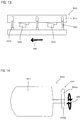
FIG. 14 is an explanatory drawing showing a vibration generating motor. - A method for manufacturing an animal excrement disposal material according to the present invention is now explained below with reference to
FIGS. 1 to 14 . The "animal" in an embodiment of this invention widely includes vertebrates (mammals, reptiles, birds and amphibians) and invertebrates, and typically represents pets such as cats, dogs, rabbits and hamsters. -
FIG 1 is a sectional view of the animal excrement disposal material manufactured by the manufacturing method according to the present invention. The animalexcrement disposal material 100 includes acore layer 110, acolored layer 120 formed in a surface of thecore layer 110 and acovering layer 130 formed on a surface of thecolored layer 120. The animalexcrement disposal material 100, thecore layer 110, thecolored layer 120 and thecovering layer 130 are example embodiments that correspond to the "animal excrement disposal material", the "core layer", the "colored layer" and the "covering layer", respectively, according to the present invention. - The covering
layer 130 exhibits white in a dry state so that coloration of thecolored layer 120 is made less visible. Specifically, surfaces of asecond pulp 131 and a second superabsorbent polymer 132 which form thecovering layer 130 diffusely reflect light, so that thecovering layer 130 exhibits white. On the other hands, thecovering layer 130 improves light transmittance in a wet state. Therefore, in the wet state, a user can recognize the coloration of thecolored layer 120 more clearly from a surface side of the animal excrement disposal material. - Further, in this invention, the "coloration" means not only color, but it also includes lightness, brightness and gradation.
- The
core layer 110 has acrack part 110A which is recessed from a surface of thecore layer 110, and thecovering layer 130 is formed in thecrack part 110A as well. Therefore, thecovering layer 130 is prevented from easily peeling from thecore layer 110. - The
core layer 110 is composed of afirst pulp 111 and a first superabsorbent polymer 112. - The
first pulp 111 has a fiber length of 20 mm or less and a fiber diameter of 200 µm or less. - The first super
absorbent polymer 112 has a particle diameter of 2 mm or less. - As explained in more detail below, the
colored layer 120 is formed by ejecting a liquid coloring agent 1201 onto a granularcore layer material 1102 for forming thecore layer 110 in such a manner that the coloring agent 1201 is unevenly applied to thecore layer material 1102. - Specifically, the
core layer 110 has afirst region 110B in which thecolored layer 120 is formed by impregnation of thecore layer 110 with the liquid coloring agent 1201. Further, thecore layer 110 has asecond region 110C in which thecolored layer 120 is formed by curing of the liquid coloring agent 1201 on the surface of thecore layer 110. Moreover, thecore layer 110 has athird region 110D to which the liquid coloring agent 1201 is not applied. - Further, the "coloring agent" in this invention is used for coloration of an object and includes chemically synthesized agents and agents extracted from natural products. Specifically, the "coloring agent" as used in this invention is a concept including dyestuffs, pigment and other similar agents for coloring.
- In this invention, the
core layer 110 has the "uneven"colored layer 120, and the liquid coloring agent 1201 is "unevenly" applied to the granularcore layer material 1102. The "uneven" states are now explained. - First, when the
core layer 110 has at least two regions of thefirst region 110B, thesecond region 110C and thethird region 110D, thecolored layer 120 or the state of application of the liquid coloring agent 1201 is defined as being "uneven". - Further, when the
core layer 110 has only thefirst region 110B of the three regions and thefirst region 110B has a region having a different depth of impregnation of thecore layer 110 with the liquid coloring agent 1201 from the other region, thecolored layer 120 or the state of application of the liquid coloring agent 1201 is defined as being "uneven". - Moreover, when the
core layer 110 has only thesecond region 110C of the three regions and thesecond region 110C has a region having a different thickness of thecolored region 120 on thecore layer 110, thecolored layer 120 or the state of application of the liquid coloring agent 1201 is defined as being "uneven". - The
covering layer 130 is composed of thesecond pulp 131, the second superabsorbent polymer 132 and a water-absorbent adhesive 133. - The
second pulp 131 has a fiber length of 20 mm or less and a fiber diameter of 200 µm or less. Further, thesecond pulp 131 has a shorter fiber length than thefirst pulp 111, so that thesecond pulp 131 can be satisfactorily connected to the surface of the core layer 110 (the colored layer 120). - The second super
absorbent polymer 132 has a particle diameter of 2 mm or less. - The water-absorbent adhesive 133 exhibits adhesiveness by absorbing liquid (or moisture). Specifically, starch is used as the water-
absorbent adhesive 133. The starch can be appropriately selected from those used for this type of animal excrement disposal materials, such as tapioca starch and potato starch. - Operation of the animal
excrement disposal material 100 according to an embodiment of the present invention is now explained. - A user puts an adequate amount of the animal
excrement disposal material 100 into a container. An animal excretes onto the animalexcrement disposal material 100. The light transmittance of thecovering layer 130 of the animalexcrement disposal material 100 is increased by absorbing liquid excrement. As a result, the user can recognize the coloration of thecolored layer 120 from the outside of the animalexcrement disposal material 100. - In the animal
excrement disposal material 100, thesecond pulp 131 of thecovering layer 130 first retains liquid. Subsequently, thefirst pulp 111 of thecore layer 110 retains liquid. Next, the second superabsorbent polymer 132 of thecovering layer 130 retains liquid which is transferred from thesecond pulp 131 as well as directly transferred liquid animal excrement. Then the first superabsorbent polymer 112 of thecore layer 110 retains liquid. Thereafter, the water-absorbent adhesive 133 exhibits adhesiveness by absorbing liquid. - The above-described order of retaining liquid excrement is a theoretical order. The liquid retaining order of each component may be changed according to the formation state of the
colored layer 120 or the amount of liquid excrement. Further, each component may simultaneously retain liquid. - The
colored layer 120 is unevenly provided in thecore layer 110. Specifically, thecolored layer 120 has a region impregnated with the liquid coloring agent 1201 in a region of thefirst region 110B of thecore layer 110 which is shallow from the surface of thecore layer 110. Animal excrement is smoothly absorbed into thecore layer 110 by passing through this region. Further, thethird region 110D of thecore layer 110 does not have the coloredlayer 120. Therefore, the animal excrement is smoothly absorbed into thecore layer 110 by passing through thethird region 110D. - Specifically, in the animal
excrement disposal material 100 according to the present invention, by provision of the unevenly formedcolored layer 120, the animal excrement can be smoothly taken into thecore layer 110. - The second super
absorbent polymer 132 of thecovering layer 130 swells by absorbing liquid and exhibits tackiness. Therefore, the animalexcrement disposal materials 100 adjacent to each other are bonded together. As a result, an aggregate of the animalexcrement disposal materials 100 is formed. At this time, even if tackiness of the second superabsorbent polymer 132 is reduced by drying, the water-absorbent adhesive 133 maintains adhesiveness. Therefore, the aggregated state of the animalexcrement disposal materials 100 can be maintained. - Therefore, the user can recognize animal excretion by the
colored layer 120 and then easily remove the aggregate of the animalexcrement disposal materials 100 from the container. - A process of manufacturing the animal excrement disposal material according to the present invention is now explained with reference to
FIG. 4 . - A granulating step S1 includes a raw material pulverizing step S11, a mixing/agitating step S12, a compressing step S13 and a cutting step S14. The granulating step S1 is followed by a covering step S2. The covering step S2 includes a coloring agent applying step S21 and a covering material covering step S22. The covering step S2 is followed by a sizing step S3, a drying step S4 and an adjusting step S5. In this manner, the animal excrement disposal material is completed.
- First, the granulating step S1 is explained. In the raw material pulverizing step S11, pulp and waste material which are generated in a process of manufacturing disposable diapers are used as a raw material. The raw material is pulverized by a pulverizer 300 (shredder) which is described below. The raw material pulverized by the
pulverizer 300 is referred to as a pulverized material. - The raw material pulverizing step S11 is an example embodiment that corresponds to the "step of obtaining a pulverized material by pulverizing a raw material" according to the present invention.
- In the mixing/agitating step S12, the pulverized material is kneaded after adding water. In the kneading step, the water content of the kneaded mixture is checked. Specifically, the input amount of water or the raw material is adjusted such that the kneaded mixture has a prescribed water content.
- Further, in the mixing/agitating step S12, the pulp for forming the
first pulp 111 is machined to have a fiber length of 2 mm or less, and the super absorbent polymer for forming the first super absorbent polymer is machined to have a particle diameter of 28 µm or less. - In this manner, a kneaded
core layer material 1101 is formed. - In the compressing step S13, the raw material is dehydrated and then compressed by a roller. At this stage, the water content of the kneaded
core layer material 1101 is adjusted to be 15 to 25 % by weight. - The compressing step S13 in the manufacturing process is explained with reference to
FIGS. 5 to 7 . The kneadedcore layer material 1101 is granulated by anextrusion compression granulator 200. As theextrusion compression granulator 200, for example, an extrusion compression granulator disclosed in Japanese Unexamined Patent Application Publication (JP-A) No. 2011-172515 - An essential part of the
extrusion compression granulator 200 is formed by a die table 210 having acharge port 220, adischarge port 240 and apassage 230 connecting thecharge port 220 and thedischarge port 240. - First, as shown in
FIG. 5 , the kneadedcore layer material 1101 is transferred toward thecharge port 220 of the die table 210. This transfer of the kneadedcore layer material 1101 in a machine direction MD is realized by a known structure in an extrusion compression granulator of this type. - Next, as shown in
FIG. 6 , the kneadedcore layer material 1101 transferred in the machine direction MD passes through thepassage 230. At this time, the kneadedcore layer material 1101 receives a prescribed pressure. - Then, as shown in
FIG. 7 , the kneadedcore layer material 1101 is discharged from thedischarge port 240 of the die table 210. At this time, the kneadedcore layer material 1101 is abruptly released from pressure and cracks. The cracks form thecrack parts 110A in thecore layer 110 of the animalexcrement disposal material 100. - The kneaded
core layer material 1101 discharged from thedischarge port 240 of theextrusion compression granulator 200 has a diameter of 2.5 mm to 8 mm. - In the cutting step S14, the kneaded
core layer material 1101 extruded by theextrusion compression granulator 200 is cut by a rotary blade to obtain the granularcore layer material 1102. - The covering step S2 is now explained. Granules obtained in the cutting step S14 are transferred to the coloring agent applying step S21. In the coloring agent applying step S21, a coloring agent solution is applied to the granular
core layer material 1102. Specifically, the coloring agent solution is ejected onto the granules within a rotating drum. A colored core layer material is obtained from the granularcore layer material 1102 by this step. This coloring agent applying step S21 is described in more detail below. - In the covering material covering step S22, the colored core layer material is covered with the covering material. The covering material is a mixture of the
second pulp 131, the second superabsorbent polymer 132 and the water-absorbent adhesive 133. - Further, a known covering machine is used to cover the colored core layer material with the covering material.
- The colored core layer material covered with the covering material is transferred onto a belt conveyor. The covering material is fixed onto the colored core layer material by vibration of the belt conveyor, which is described in more detail below.
- A covered granular material is obtained from the colored core layer material by this step.
- In the sizing step S3, the covered granular material is sorted by the size. Specifically, the covered granular material having a small particle diameter is sorted by vibrating a sieve having a certain mesh size
- In the drying step S4, hot air is blown onto the covered granular material from below, so that the covered granular material is dried while repeatedly floating and dropping. As a result, the surface of the covered granular material is compacted.
- In the adjusting step S5, the granules sorted based on a result of a quality test are blended so as to obtain desired animal excrement disposal materials as a whole.
- The animal excrement disposal material is completed through the above-described process steps.
- In the steps S1 to S5 of the present invention, various methods can be appropriately used to transfer the materials (the kneaded
core layer material 1101, the granularcore layer material 1102 and the covered granular material) from one step to the next. For example, a mechanical transfer means such as a belt conveyor may be used. Further, a material obtained in one step can also be carried in a container to the next step, for example, by a forklift, a cart or human power. - The raw material pulverizing step S11 and a manufacturing device related thereto are now explained with reference to
FIGS. 8 to 9 . - The
pulverizer 300 has a known structure of a pulverizer of this type. Specifically, thepulverizer 300 has acharge port 310 for the raw material, apulverization chamber 320 for pulverizing the raw material, apulverizing mechanism 330 provided within thepulverization chamber 320, amesh screen 340 having a plurality ofopenings 341 through which the raw material pulverized by thepulverizing mechanism 330 is passed, and adischarge port 350 formed contiguously to theopenings 341 of themesh screen 340. The raw material is turned into the pulverized material by charging from thecharge port 310 and passing through thedischarge port 350. - The
pulverizer 300, thecharge port 310, thepulverization chamber 320, thepulverizing mechanism 330, theopenings 341, themesh screen 340 and thedischarge port 350 are example embodiments that correspond to the "pulverizer", the "charge port", the "pulverization chamber", the "pulverizing mechanism", the "openings", the "mesh screen" and the "discharge port", respectively, according to the present invention. - The
pulverizer 300 includes a first pulverizer and a second pulverizer arranged contiguously to the first pulverizer. The first and second pulverizers are connected to each other in series. - The first pulverizer and the second pulverizer are example embodiments that correspond to the "first pulverizer" and the "second pulverizer", respectively, according to the present invention.
- The first pulverizer has a first mesh screen and first openings formed in the first mesh screen. The first mesh screen and the first openings are example embodiments that correspond to the "first mesh screen" and the "first openings", respectively, according to the present invention.
- The second pulverizer has a second mesh screen and second openings formed in the second mesh screen. The second mesh screen and the second openings are example embodiments that correspond to the "second mesh screen" and the "second openings", respectively, according to the present invention.
- The first openings are formed to be larger than the second openings.
- In the embodiment according to the present invention, both the first openings and the second openings have a circular shape. In this case, the first openings have a larger diameter than the second openings.
- Specifically, each of the first openings has a diameter of 10 mm and each of the second openings has a diameter of 2 mm. Thus, the first opening has a larger area than the second opening.
- Further, the first and second openings do not necessarily have to be circular.
- The
pulverizing mechanism 330 includes arotating body 331 and a plurality ofblades 332 formed on therotating body 331. - The rotation speed of the
rotating body 331 is 1,000 rpm. Further, the rotation speed is the same in the first pulverizer and the second pulverizer. - In the above-described embodiment, the
pulverizer 300 is explained as being formed by the first and second pulverizers. As thepulverizer 300, however, a single pulverizer may be used. Further, the size of the openings in the mesh screen may be appropriately selected. - The coloring agent applying step S21 and a device related thereto are now explained with reference to
FIGS. 10 to 12 . - The step of applying the coloring agent to the granular
core layer material 1102 has a step of floating the granularcore layer material 1102 and a step of ejecting the liquid coloring agent 1201 onto the floated granularcore layer material 1102. A coloringagent applying machine 400 is used to eject the liquid coloring agent 1201 onto the floated granularcore layer material 1102. - In the step of applying the liquid coloring agent 1201 to the granular
core layer material 1102, the coloringagent applying machine 400 is used which has arotating drum 410, a coloringagent applying chamber 420 formed inside therotating drum 410 to receive the granularcore layer material 1102, and anozzle 440 for applying the liquid coloring agent 1201 to the granularcore layer material 1102. Thenozzle 440 is connected to apipe 430 for transporting the liquid coloring agent 1201. - In the step of floating the granular
core layer material 1102, the granularcore layer material 1102 is separated from aninner wall surface 420A which forms the coloringagent applying chamber 420. In this invention, the state of the granularcore layer material 1102 separated from theinner wall surface 420A of the coloringagent applying chamber 420 is referred to as a "floated" or "floating" state. - The "floated" state of the granular
core layer material 1102 separated from theinner wall surface 420A of the coloringagent applying chamber 420 is explained with reference toFIG. 12 . The granularcore layer material 1102 is conveyed into the coloringagent applying chamber 420 of therotating drum 410. Therotating drum 410 is rotated by a rotating mechanism (not shown). The granularcore layer material 1102 is pressed against theinner wall surface 420A of the coloringagent applying chamber 420 by centrifugal force caused by rotation of therotating drum 410. In this state, the centrifugal force acting on the granularcore layer material 1102 is greater than the gravity. - When the rotation of the
rotating drum 410 proceeds, however, the gravity becomes greater than the centrifugal force acting on the granularcore layer material 1102. At this time, the granularcore layer material 1102 separates from theinner wall surface 420A and then drops in a direction of an arrow GD. Specifically, the granularcore layer material 1102 "floats". The granularcore layer material 1102 floats while rotating. - The
nozzle 440 is directed to the floating granularcore layer material 1102 and ejects the liquid coloring agent 1201 onto the granularcore layer material 1102. At this time, the amount of the liquid coloring agent 1201 which is sprayed like a shower is smaller than an amount required for covering the whole surface area of the granularcore layer material 1102 conveyed into the coloringagent applying chamber 420. - Specifically, the liquid coloring agent 1201 is applied to the granular
core layer material 1102 while the granularcore layer material 1102 is rotated and floated. - Therefore, a region of the granular
core layer material 1102 to which a small amount of the liquid coloring agent 1201 is applied is impregnated with the small amount of the liquid coloring agent 1201 and forms thefirst region 110B in thecore layer 110. - Further, another region of the granular
core layer material 1102 to which a large amount of the liquid coloring agent 1201 is applied is impregnated with the large amount of liquid coloring agent 1201, and some of the liquid coloring agent 1201 which cannot be impregnated into this region is dried and cured in this region of the granularcore layer material 1102. Thus, thecolored layer 120 is formed on the surface of this region of the granularcore layer material 1102. In this manner, this region forms thesecond region 110C in thecore layer 110. - Further, the liquid coloring agent 1201 is not applied to the whole region of the granular
core layer material 1102. A region to which the liquid coloring agent 1201 is not applied forms thethird region 110D in thecore layer 110. - In this manner, the
core layer 110 having the unevencolored layer 120 is formed. - In the above description, the granular
core layer material 1102 "floats" by balance between the centrifugal force of therotating drum 410 and the gravity which act on the granularcore layer material 1102. However, the "floating" state of the granularcore layer material 1102 according to the present invention can also be realized in other states. For example, when the granularcore layer material 1102 has a cylindrical shape, an end of the granularcore layer material 1102 in a longitudinal direction comes in contact with theinner wall surface 420A of therotating drum 410. At this time, the granularcore layer material 1102 is flicked by the rotatinginner wall surface 420A and separated from theinner wall surface 420A. In such a state, the granularcore layer material 1102 is also "floated" with respect to theinner wall surface 420A. - The specific conditions in the coloring agent applying step S21 are as follows.
- The size of the granular
core layer material 1102 is 2 to 10 mm in diameter. The ejection amount of the liquid coloring agent 1201 from thenozzle 440 is 0.7 ℓ/s. The diameter of therotating drum 410 is 800 mm. The rotation speed of therotating drum 410 is 7.5 to 11.25 rpm/min. - The covering material covering step S22 and a device related thereto is now explained with reference to
FIGS. 13 to 14 . - The step of covering the granular
core layer material 1102 with the covering material (not shown) includes a step of disposing the covering material on the granularcore layer material 1102 and a step of applying vibration to the granularcore layer material 1102 having the covering material disposed thereon. - The covering material is composed of the
second pulp 131 that is formed to be capable of retaining liquid animal excrement, a second superabsorbent polymer 132 that is formed to be capable of retaining liquid excrement transferred from (retained in) thesecond pulp 131, and the water-absorbent adhesive 133 that is formed to be capable of exhibiting adhesiveness by absorbing liquid. This covering material forms thecovering layer 130 of the animalexcrement disposal material 100. - In an operation of disposing the covering material on the granular
core layer material 1102, a known device such as a rotating drum as disclosed in Japanese Unexamined Patent Application Publication (JP-A) No. 2003-274780 - In the step of applying vibration to the granular
core layer material 1102 having the covering material disposed thereon, the granularcore layer material 1102 is conveyed by abelt conveyor 500 shown inFIG. 13 . Thebelt conveyor 500 has aconveyance part 510 that conveys the granularcore layer material 1102, and avibration generating part 530 that applies vibration to theconveyance part 510. Vibration generated by thevibration generating part 530 is absorbed by adamper 520, so that the vibration is prevented from being easily transmitted to a base 540 for supporting thebelt conveyor 500. - The
vibration generating part 530 includes a vibration generating motor 550. The vibration generating motor 550 has a body 551 having a known mechanism for rotating a shaft 552. - A
weight 553 is provided on the shaft 552. Theweight 553 has afirst weight region 553A and asecond weight region 553B which are formed on opposite sides of the shaft 552. Thefirst weight region 553A and thesecond weight region 553B have different lengths in the longitudinal direction. By provision of theweight 553 having such a structure, the vibration generating motor 550 can vibrate theconveyance part 510. - The covering material is pressed against the granular
core layer material 1102 by vibration which is applied to theconveyance part 510 by thevibration generating part 530. Specifically, theconveyance part 510 is vibrated, so that the granularcore layer material 1102 is also vibrated. Thus, the granularcore layer material 1102 jumps up from theconveyance part 510 and drops onto theconveyance part 510. By the drop of the granularcore layer material 1102 onto theconveyance part 510, the covering material is pressed against the granularcore layer material 1102. - In the covering material covering step S22, the granular
core layer material 1102 contains water. Specifically, the granularcore layer material 1102 retains water added in the mixing/agitating step S12 and the coloring agent applying step S21. Therefore, the first superabsorbent polymer 112 of the granularcore layer material 1102 is swollen and exhibits tackiness. The covering material is bonded to the granularcore layer material 1102 by the tacky first superabsorbent polymer 112. Further, the covering material is reliably fixed to the granularcore layer material 1102 by vibration of thevibration generating part 530. - In the above-described
belt conveyor 500, vibration is forcibly applied to theconveyance part 510 by thevibration generating part 530. Depending on the structure of thebelt conveyor 500, however, prescribed vibration may be applied to theconveyance part 510 merely by driving theconveyance part 510. In such a case, it is not necessary to provide thevibration generating part 530 in thebelt conveyor 500. - The specific conditions in the covering material covering step S22 are as follows.
- The size of the granular
core layer material 1102 is 2 to 10 mm in diameter. The percentage of thesecond pulp 131 in the covering material is 60 % by weight. The percentage of the second superabsorbent polymer 132 in the covering material is 10 % by weight. The percentage of the water-absorbent adhesive 133 in the covering material is 30 % by weight. The operation conditions of the vibration generating motor 550 are 1.5 k and (the rotation speed of) 1,700 rpm. The time it takes for the granularcore layer material 1102 to pass through thebelt conveyor 500 is 90 seconds. - The method and the device for manufacturing an animal excrement disposal material according to the present invention are not limited to those as described above. Especially, a known manufacturing device can be appropriately selected as the manufacturing device.
- The animal
excrement disposal material 100 is an example embodiment that corresponds to the "animal excrement disposal material" according to the present invention. Thecore layer 110 is an example embodiment that corresponds to the "core layer" according to the present invention. Thecolored layer 120 is an example embodiment that corresponds to the "colored layer" according to the present invention. Thecovering layer 130 is an example embodiment that corresponds to the "covering layer" according to the present invention. The raw material pulverizing step S11 is an example embodiment that corresponds to the "step of obtaining a pulverized material by pulverizing a raw material" according to the present invention. Thepulverizer 300, thecharge port 310, thepulverization chamber 320, thepulverizing mechanism 330, theopenings 341, themesh screen 340 and thedischarge port 350 are example embodiments that correspond to the "pulverizer", the "charge port", the "pulverization chamber", the "pulverizing mechanism", the "openings", the "mesh screen" and the "discharge port", respectively, according to the present invention. The first pulverizer and the second pulverizer are example embodiments that correspond to the "first pulverizer" and the "second pulverizer", respectively, according to the present invention. The first mesh screen and the first openings are example embodiments that correspond to the "first mesh screen" and the "first openings", respectively, according to the present invention. The second mesh screen and the second openings are example embodiments that correspond to the "second mesh screen" and the "second openings", respectively, according to the present invention. - In view of the nature of the above-described invention, various features can be provided as follows.
- A method for manufacturing an animal excrement disposal material, comprising:
- a step of obtaining a pulverized material by pulverizing a raw material and a step of granulating the pulverized material,
- in the step of obtaining the pulverized material, the pulverized material is obtained by pulverizing the raw material by a pulverizer, and
- the pulverizer has a charge port for the raw material, a pulverization chamber for pulverizing the raw material, a pulverizing mechanism provided within the pulverization chamber, a mesh screen having a plurality of openings through which the raw material pulverized by the pulverizing mechanism is passed, and a discharge port formed contiguously to the openings of the mesh screen.
- The manufacturing method as defined in aspect 1, wherein the pulverizer includes a first pulverizer and a second pulverizer arranged contiguously to the first pulverizer.
- The manufacturing method as defined in aspect 2, wherein:
- the first pulverizer has a first mesh screen and first openings formed in the first mesh screen,
- the second pulverizer has a second mesh screen and second openings formed in the second mesh screen, and
- the first openings are formed to be larger than the second openings.
- The manufacturing method as defined in aspect 3, wherein the first openings have a larger diameter than the second openings.
- The manufacturing method as defined in aspect 4, wherein each of the first openings has a diameter of 10 mm and each of the second openings has a diameter of 2 mm.
- The manufacturing method as defined in any one of aspects 3 to 5, wherein each of the first openings has a larger area than each of the second openings.
- The manufacturing method as defined in any one of aspects 1 to 6, wherein the pulverizing mechanism comprises a rotating body and a plurality of blades formed on the rotating body.
- The manufacturing method as defined in aspect 7, wherein a rotation speed of the rotating body is 1,000 rpm.
- The manufacturing method as defined in any one of aspects 1 to 8, wherein the raw material is pulp and super absorbent polymer which are generated in a process of manufacturing disposable diapers.
- The manufacturing method as defined in any one of aspects 1 to 9, wherein the raw material pulverized in the step of pulverizing the raw material is subjected to a step of adding water and kneading.
- The manufacturing method as defined in any one of aspects 1 to 10, wherein the raw material subjected to the step of adding water and kneading has a water content of 15 to 25 percent.
- The manufacturing method as defined in aspect 11, wherein the pulp in the raw material subjected to the step of adding water and kneading has a fiber length of 2 mm or less.
- The manufacturing method as defined in aspect 12, wherein the super absorbent polymer in the raw material subjected to the step of adding water and kneading has a particle diameter of 28 µm or less.
- The manufacturing method as defined in any one of aspects 1 to 13, wherein the animal excrement disposal material comprises a core layer, a colored layer formed in the core layer and a covering layer that covers the core layer having the colored layer.
- The manufacturing method as defined in aspect 14, wherein the core layer comprises a first primary water-retaining member that is formed to be capable of retaining liquid animal excrement, and a first secondary water-retaining member that is formed to be capable of retaining liquid excrement transferred from (retained in) the first primary water-retaining member.
- The manufacturing method as defined in aspect 14 or 15, wherein the colored layer is unevenly formed in the core layer.
- The manufacturing method as defined in any one of aspects 14 to 16, wherein the covering layer comprises a second primary water-retaining member that is formed to be capable of retaining liquid animal excrement, a second secondary water-retaining member that is formed to be capable of retaining liquid excrement transferred from the second primary water-retaining member, and a water-absorbent adhesive that is formed to be capable of exhibiting adhesiveness by absorbing liquid.
- The manufacturing method as defined in any one of aspects 14 to 17, wherein the pulp forms the first primary water-retaining member.
- The manufacturing method as defined in any one of aspects 14 to 17, wherein the super absorbent polymer forms the first secondary water-retaining member.
- A device for manufacturing an animal excrement disposal material, comprising:
- a pulverizer for pulverizing a raw material, wherein:
- the pulverizer has a charge port for the raw material, a pulverization chamber for pulverizing the raw material, a pulverizing mechanism provided within the pulverization chamber, a mesh screen having a plurality of openings through which the raw material pulverized by the pulverizing mechanism is passed, and a discharge port formed contiguously to the openings of the mesh screen.
- The manufacturing device as defined in aspect 20, wherein the pulverizer includes a first pulverizer and a second pulverizer arranged contiguously to the first pulverizer.
- The manufacturing device as defined in aspect 21, wherein:
- the first pulverizer has a first mesh screen and first openings formed in the first mesh screen,
- the second pulverizer has a second mesh screen and second openings formed in the second mesh screen, and
- the first openings are formed to be larger than the second openings.
- The manufacturing device as defined in aspect 22, wherein the first openings have a larger diameter than the second openings.
- The manufacturing device as defined in aspect 23, wherein each of the first openings has a diameter of 10 mm and each of the second openings has a diameter of 2 mm.
- The manufacturing device as defined in any one of aspects 22 to 24, wherein each of the first openings has a larger area than each of the second openings.
- The manufacturing device as defined in any one of aspects 20 to 25, wherein the pulverizing mechanism comprises a rotating body and a plurality of blades formed on the rotating body.
- The manufacturing device as defined in aspect 26, wherein a rotation speed of the rotating body is 1,000 rpm.
-
- 100
- animal excrement disposal material
- 110
- core layer
- 1101
- kneaded core layer material
- 1102
- granular core layer material
- 1102A
- dropping granular core layer material
- 110A
- crack part
- 110B
- first region
- 110C
- second region
- 110D
- third region
- 111
- first pulp (first primary water-retaining member)
- 112
- first super absorbent polymer (first secondary water-retaining member)
- 120
- colored layer
- 1201
- liquid coloring agent
- 121
- coloring agent part
- 130
- covering layer
- 131
- second pulp (second primary water-retaining member)
- 132
- second super absorbent polymer (second secondary water-retaining member)
- 133
- water-absorbent adhesive
- 200
- extrusion compression granulator
- 210
- die table
- 220
- charge port
- 230
- passage
- 240
- discharge port
- 300
- pulverizer
- 310
- charge port
- 320
- pulverization chamber
- 330
- pulverizing mechanism
- 331
- rotating body
- 332
- blade
- 340
- mesh screen
- 341
- opening
- 350
- discharge port
- 400
- coloring agent applying machine
- 410
- rotating drum
- 420
- coloring agent applying chamber
- 420A
- inner wall surface
- 430
- (liquid transport) pipe
- 440
- nozzle
- 500
- belt conveyor
- 510
- conveyance part
- 520
- damper
- 530
- vibration generating part
- 540
- base
- 550
- vibration generating motor
- 551
- body
- 552
- shaft
- 553
- weight
- 553A
- first weight region
- 553B
- second weight region
- S1
- granulating step
- S11
- raw material pulverizing step
- S12
- mixing/agitating step
- S13
- compressing step
- S14
- cutting step
- S2
- covering step
- S21
- coloring agent applying step
- S22
- covering material covering step
- S3
- sizing step
- S4
- drying step
- S5
- adjusting step
- GD
- dropping direction
- MD
- machine direction
Claims (14)
- A method for manufacturing an animal excrement disposal material, comprising:a step of obtaining a pulverized material by pulverizing a raw material and a step of granulating the pulverized material,in the step of obtaining the pulverized material, the pulverized material is obtained by pulverizing the raw material by a pulverizer, andthe pulverizer has a charge port for the raw material, a pulverization chamber for pulverizing the raw material, a pulverizing mechanism provided within the pulverization chamber, a mesh screen having a plurality of openings through which the raw material pulverized by the pulverizing mechanism is passed, and a discharge port formed contiguously to the openings of the mesh screen.
- The manufacturing method as defined in claim 1, wherein the pulverizer includes a first pulverizer and a second pulverizer arranged contiguously to the first pulverizer.
- The manufacturing method as defined in claim 2, wherein:the first pulverizer has a first mesh screen and first openings formed in the first mesh screen,the second pulverizer has a second mesh screen and second openings formed in the second mesh screen, andthe first openings are formed to be larger than the second openings.
- The manufacturing method as defined in claim 3, wherein the first openings have a larger diameter than the second openings.
- The manufacturing method as defined in claim 3 or 2, wherein each of the first openings has a larger area than each of the second openings.
- The manufacturing method as defined in any one of claims 1 to 5, wherein the pulverizing mechanism comprises a rotating body and a plurality of blades formed on the rotating body.
- The manufacturing method as defined in any one of claims 1 to 6, wherein the raw material is pulp and super absorbent polymer which are generated in a process of manufacturing disposable diapers.
- The manufacturing method as defined in any one of claims 1 to 7, wherein the animal excrement disposal material comprises a core layer, a colored layer formed in the core layer and a covering layer that covers the core layer having the colored layer.
- A device for manufacturing an animal excrement disposal material, comprising:a pulverizer for pulverizing a raw material, wherein:the pulverizer has a charge port for the raw material, a pulverization chamber for pulverizing the raw material, a pulverizing mechanism provided within the pulverization chamber, a mesh screen having a plurality of openings through which the raw material pulverized by the pulverizing mechanism is passed, and a discharge port formed contiguously to the openings of the mesh screen.
- The manufacturing device as defined in claim 9, wherein the pulverizer includes a first pulverizer and a second pulverizer arranged contiguously to the first pulverizer.
- The manufacturing device as defined in claim 10, wherein:the first pulverizer has a first mesh screen and first openings formed in the first mesh screen,the second pulverizer has a second mesh screen and second openings formed in the second mesh screen, andthe first openings are formed to be larger than the second openings.
- The manufacturing device as defined in claim 11, wherein the first openings have a larger diameter than the second openings.
- The manufacturing device as defined in claim 11 or 12, wherein each of the first openings has a larger area than each of the second openings.
- The manufacturing device as defined in any one of claims 9 to 13, wherein the pulverizing mechanism comprises a rotating body and a plurality of blades formed on the rotating body.
Applications Claiming Priority (2)
| Application Number | Priority Date | Filing Date | Title |
|---|---|---|---|
| JP2013060924A JP5421480B1 (en) | 2013-03-22 | 2013-03-22 | Manufacturing method of animal excrement disposal material and manufacturing apparatus thereof |
| PCT/JP2013/062965 WO2014147851A1 (en) | 2013-03-22 | 2013-05-08 | Production method for animal excrement treatment material and production device therefor |
Publications (2)
| Publication Number | Publication Date |
|---|---|
| EP2976944A1 true EP2976944A1 (en) | 2016-01-27 |
| EP2976944A4 EP2976944A4 (en) | 2016-09-14 |
Family
ID=50287242
Family Applications (1)
| Application Number | Title | Priority Date | Filing Date |
|---|---|---|---|
| EP13879112.4A Withdrawn EP2976944A4 (en) | 2013-03-22 | 2013-05-08 | METHOD FOR PRODUCING ANIMAL EXCREMENT TREATMENT MATERIAL AND CORRESPONDING PRODUCTION DEVICE |
Country Status (7)
| Country | Link |
|---|---|
| US (1) | US10130069B2 (en) |
| EP (1) | EP2976944A4 (en) |
| JP (1) | JP5421480B1 (en) |
| CN (1) | CN105263314B (en) |
| AU (1) | AU2013383612B2 (en) |
| TW (1) | TWI618482B (en) |
| WO (1) | WO2014147851A1 (en) |
Families Citing this family (4)
| Publication number | Priority date | Publication date | Assignee | Title |
|---|---|---|---|---|
| JP6042020B1 (en) * | 2016-09-05 | 2016-12-14 | 株式会社大貴 | Excrement treatment material manufacturing method and manufacturing apparatus |
| CN108739418B (en) * | 2018-04-12 | 2020-08-28 | 绍兴大纬针织机械有限公司 | Poultry is with rabbit feeding device convenient to wash |
| JP6517408B1 (en) * | 2018-06-21 | 2019-05-22 | 株式会社大貴 | Method of manufacturing water absorbing material |
| CN114451310B (en) * | 2022-01-18 | 2023-03-14 | 濮阳市农业综合行政执法支队 | Livestock and poultry excrement collecting device |
Family Cites Families (26)
| Publication number | Priority date | Publication date | Assignee | Title |
|---|---|---|---|---|
| US3676029A (en) * | 1970-04-09 | 1972-07-11 | Peter Hopkin | Pelletizing apparatus |
| JPH0731914A (en) | 1993-05-18 | 1995-02-03 | Mitsubishi Chem Corp | Coating equipment |
| JPH07205147A (en) * | 1994-01-13 | 1995-08-08 | Hitachi Zosen Sangyo Kk | Plastic waste treatment equipment |
| JP2001204288A (en) | 2000-01-27 | 2001-07-31 | Bmd:Kk | Animal waste materials |
| JP2003219746A (en) * | 2002-01-30 | 2003-08-05 | Daiki:Kk | Manufacturing method of granular waste material |
| JP3723516B2 (en) | 2002-03-20 | 2005-12-07 | ペパーレット株式会社 | Granular animal urine treatment material |
| JP2006000782A (en) | 2004-06-18 | 2006-01-05 | Pepaaretsuto Kk | Drainage absorber |
| JP2006296218A (en) * | 2005-04-15 | 2006-11-02 | Pepaaretsuto Kk | Excrement-treating material |
| JP4603952B2 (en) | 2005-08-10 | 2010-12-22 | 黒崎白土工業株式会社 | Pet toilet sand |
| JP2007043988A (en) | 2005-08-11 | 2007-02-22 | Mizusawa Ind Chem Ltd | Pet toilet sand |
| JP2007135424A (en) | 2005-11-15 | 2007-06-07 | Pepaaretsuto Kk | Excrement-treating material |
| JP4644270B2 (en) | 2008-05-15 | 2011-03-02 | 道雄 伊藤 | Excrement disposal material for pets |
| JP5301891B2 (en) * | 2008-06-19 | 2013-09-25 | 旭化成ケミカルズ株式会社 | Process for producing pellets from crystalline lactic acid-based polyester film and pellets obtained by the process |
| CN105968391A (en) * | 2009-02-20 | 2016-09-28 | 阿彻丹尼尔斯米德兰德公司 | Acidic gas permeated carboxyalkyl starch particles, extrudates, and process for making the same |
| JP4859946B2 (en) | 2009-04-10 | 2012-01-25 | 株式会社大貴 | Water absorption treatment material and method for producing the same |
| JP5149318B2 (en) | 2010-02-24 | 2013-02-20 | ペパーレット株式会社 | Extruded compression granulator for granular excrement disposal materials |
| JP5336414B2 (en) * | 2010-04-08 | 2013-11-06 | ペパーレット株式会社 | Excrement treatment material |
| JP2011218296A (en) | 2010-04-09 | 2011-11-04 | Earthlink Inc | Powder production apparatus |
| JP2011230050A (en) | 2010-04-27 | 2011-11-17 | Hitachi Chem Co Ltd | Screen for resin material-grinding machine, and method for grinding resin material |
| CN102150626A (en) * | 2011-01-12 | 2011-08-17 | 青岛正利纸业有限公司 | Granulated paper pad for pets and manufacturing method thereof |
| JP5827808B2 (en) * | 2011-02-08 | 2015-12-02 | 常陸化工株式会社 | Pet toilet sand and manufacturing method thereof |
| CN202178118U (en) * | 2011-07-26 | 2012-03-28 | 富勤环保(清远)有限公司 | Grinding mechanism for copper meter machine |
| CN102599066A (en) * | 2012-03-05 | 2012-07-25 | 江苏省协同医药生物工程有限责任公司 | Animal particle packing as well as production method and application of animal particle packing |
| CN202490649U (en) | 2012-04-06 | 2012-10-17 | 吉首市汇锋矿业有限责任公司 | Small double-mesh-screen crushing machine |
| CN102939904B (en) * | 2012-12-04 | 2015-01-14 | 青岛正利纸业有限公司 | Production method of pet padding |
| CN102939905A (en) * | 2012-12-04 | 2013-02-27 | 青岛正利纸业有限公司 | Padding material for pets |
-
2013
- 2013-03-22 JP JP2013060924A patent/JP5421480B1/en active Active
- 2013-05-08 US US14/778,858 patent/US10130069B2/en not_active Expired - Fee Related
- 2013-05-08 EP EP13879112.4A patent/EP2976944A4/en not_active Withdrawn
- 2013-05-08 WO PCT/JP2013/062965 patent/WO2014147851A1/en not_active Ceased
- 2013-05-08 CN CN201380074953.6A patent/CN105263314B/en active Active
- 2013-05-08 AU AU2013383612A patent/AU2013383612B2/en not_active Ceased
-
2014
- 2014-03-19 TW TW103110303A patent/TWI618482B/en active
Also Published As
| Publication number | Publication date |
|---|---|
| AU2013383612A1 (en) | 2015-11-12 |
| EP2976944A4 (en) | 2016-09-14 |
| CN105263314B (en) | 2018-09-11 |
| AU2013383612B2 (en) | 2018-07-12 |
| CN105263314A (en) | 2016-01-20 |
| JP2014183775A (en) | 2014-10-02 |
| TWI618482B (en) | 2018-03-21 |
| US10130069B2 (en) | 2018-11-20 |
| WO2014147851A1 (en) | 2014-09-25 |
| TW201505541A (en) | 2015-02-16 |
| US20160044890A1 (en) | 2016-02-18 |
| JP5421480B1 (en) | 2014-02-19 |
Similar Documents
| Publication | Publication Date | Title |
|---|---|---|
| JP4644270B2 (en) | Excrement disposal material for pets | |
| JP4644269B2 (en) | Excrement disposal material for pets | |
| EP2976942B1 (en) | Production method for animal excrement treatment material | |
| AU2013383612B2 (en) | Production method for animal excrement treatment material and production device therefor | |
| US20180353938A1 (en) | Method and apparatus for manufacturing excrement treatment material | |
| US5836262A (en) | Animal excretion treating material and method of manufacturing same | |
| EP2976943B1 (en) | Production method for animal excrement treatment material | |
| JP6153413B2 (en) | Manufacturing method of animal excrement disposal material and manufacturing apparatus thereof | |
| CN109661174B (en) | Manufacturing method and manufacturing apparatus of excrement treatment material | |
| JP6153417B2 (en) | Manufacturing method of animal excrement disposal material and manufacturing apparatus thereof | |
| EP0515959A2 (en) | Granules and process or obtaining them | |
| JP6388469B2 (en) | Method for producing animal excrement disposal material | |
| HK1236883A1 (en) | Separation device, and method for producing water absorbability-imparted material |
Legal Events
| Date | Code | Title | Description |
|---|---|---|---|
| PUAI | Public reference made under article 153(3) epc to a published international application that has entered the european phase |
Free format text: ORIGINAL CODE: 0009012 |
|
| 17P | Request for examination filed |
Effective date: 20151001 |
|
| AK | Designated contracting states |
Kind code of ref document: A1 Designated state(s): AL AT BE BG CH CY CZ DE DK EE ES FI FR GB GR HR HU IE IS IT LI LT LU LV MC MK MT NL NO PL PT RO RS SE SI SK SM TR |
|
| AX | Request for extension of the european patent |
Extension state: BA ME |
|
| RAP1 | Party data changed (applicant data changed or rights of an application transferred) |
Owner name: PEPARLET CO., LTD. Owner name: UNI-CHARM CORPORATION |
|
| RIN1 | Information on inventor provided before grant (corrected) |
Inventor name: OTOMO, TAKAHIRO Inventor name: TAKAGI, CHIYO Inventor name: MOCHIZUKI, SHOTARO Inventor name: SOGO, TATSUYA Inventor name: YAMADA, HIDEKAZU |
|
| RAP1 | Party data changed (applicant data changed or rights of an application transferred) |
Owner name: UNI-CHARM CORPORATION |
|
| DAX | Request for extension of the european patent (deleted) | ||
| A4 | Supplementary search report drawn up and despatched |
Effective date: 20160817 |
|
| RIC1 | Information provided on ipc code assigned before grant |
Ipc: B02C 13/10 20060101ALI20160810BHEP Ipc: A01K 1/015 20060101AFI20160810BHEP Ipc: B02C 13/13 20060101ALI20160810BHEP |
|
| STAA | Information on the status of an ep patent application or granted ep patent |
Free format text: STATUS: EXAMINATION IS IN PROGRESS |
|
| 17Q | First examination report despatched |
Effective date: 20190617 |
|
| STAA | Information on the status of an ep patent application or granted ep patent |
Free format text: STATUS: THE APPLICATION IS DEEMED TO BE WITHDRAWN |
|
| 18D | Application deemed to be withdrawn |
Effective date: 20220825 |