EP2976151B1 - Pipette tip containing reagent pad - Google Patents
Pipette tip containing reagent pad Download PDFInfo
- Publication number
- EP2976151B1 EP2976151B1 EP14770970.3A EP14770970A EP2976151B1 EP 2976151 B1 EP2976151 B1 EP 2976151B1 EP 14770970 A EP14770970 A EP 14770970A EP 2976151 B1 EP2976151 B1 EP 2976151B1
- Authority
- EP
- European Patent Office
- Prior art keywords
- tube
- capillary
- pipette
- interior cavity
- sample
- Prior art date
- Legal status (The legal status is an assumption and is not a legal conclusion. Google has not performed a legal analysis and makes no representation as to the accuracy of the status listed.)
- Active
Links
Images


Classifications
-
- B—PERFORMING OPERATIONS; TRANSPORTING
- B01—PHYSICAL OR CHEMICAL PROCESSES OR APPARATUS IN GENERAL
- B01L—CHEMICAL OR PHYSICAL LABORATORY APPARATUS FOR GENERAL USE
- B01L3/00—Containers or dishes for laboratory use, e.g. laboratory glassware; Droppers
- B01L3/02—Burettes; Pipettes
- B01L3/0275—Interchangeable or disposable dispensing tips
-
- B—PERFORMING OPERATIONS; TRANSPORTING
- B01—PHYSICAL OR CHEMICAL PROCESSES OR APPARATUS IN GENERAL
- B01L—CHEMICAL OR PHYSICAL LABORATORY APPARATUS FOR GENERAL USE
- B01L3/00—Containers or dishes for laboratory use, e.g. laboratory glassware; Droppers
- B01L3/02—Burettes; Pipettes
- B01L3/021—Pipettes, i.e. with only one conduit for withdrawing and redistributing liquids
-
- B—PERFORMING OPERATIONS; TRANSPORTING
- B01—PHYSICAL OR CHEMICAL PROCESSES OR APPARATUS IN GENERAL
- B01L—CHEMICAL OR PHYSICAL LABORATORY APPARATUS FOR GENERAL USE
- B01L2200/00—Solutions for specific problems relating to chemical or physical laboratory apparatus
- B01L2200/02—Adapting objects or devices to another
- B01L2200/026—Fluid interfacing between devices or objects, e.g. connectors, inlet details
-
- B—PERFORMING OPERATIONS; TRANSPORTING
- B01—PHYSICAL OR CHEMICAL PROCESSES OR APPARATUS IN GENERAL
- B01L—CHEMICAL OR PHYSICAL LABORATORY APPARATUS FOR GENERAL USE
- B01L2200/00—Solutions for specific problems relating to chemical or physical laboratory apparatus
- B01L2200/16—Reagents, handling or storing thereof
-
- B—PERFORMING OPERATIONS; TRANSPORTING
- B01—PHYSICAL OR CHEMICAL PROCESSES OR APPARATUS IN GENERAL
- B01L—CHEMICAL OR PHYSICAL LABORATORY APPARATUS FOR GENERAL USE
- B01L2300/00—Additional constructional details
- B01L2300/08—Geometry, shape and general structure
- B01L2300/0809—Geometry, shape and general structure rectangular shaped
- B01L2300/0825—Test strips
-
- B—PERFORMING OPERATIONS; TRANSPORTING
- B01—PHYSICAL OR CHEMICAL PROCESSES OR APPARATUS IN GENERAL
- B01L—CHEMICAL OR PHYSICAL LABORATORY APPARATUS FOR GENERAL USE
- B01L2300/00—Additional constructional details
- B01L2300/08—Geometry, shape and general structure
- B01L2300/0832—Geometry, shape and general structure cylindrical, tube shaped
- B01L2300/0838—Capillaries
-
- B—PERFORMING OPERATIONS; TRANSPORTING
- B01—PHYSICAL OR CHEMICAL PROCESSES OR APPARATUS IN GENERAL
- B01L—CHEMICAL OR PHYSICAL LABORATORY APPARATUS FOR GENERAL USE
- B01L2300/00—Additional constructional details
- B01L2300/12—Specific details about materials
-
- B—PERFORMING OPERATIONS; TRANSPORTING
- B01—PHYSICAL OR CHEMICAL PROCESSES OR APPARATUS IN GENERAL
- B01L—CHEMICAL OR PHYSICAL LABORATORY APPARATUS FOR GENERAL USE
- B01L2400/00—Moving or stopping fluids
- B01L2400/04—Moving fluids with specific forces or mechanical means
- B01L2400/0475—Moving fluids with specific forces or mechanical means specific mechanical means and fluid pressure
- B01L2400/0481—Moving fluids with specific forces or mechanical means specific mechanical means and fluid pressure squeezing of channels or chambers
Definitions
- This disclosure relates to pipettes for aspirating, diluting and dispensing fluids, especially samples of bodily fluids for medical diagnostic purposes.
- Pipettes are common tools used in medical diagnostic laboratories to transport measured volumes of bodily fluid samples, such as blood and urine.
- pipettes have a cylinder, graduated or not, that can be filled with a fluid using a pressure mechanism on one end of the cylinder.
- Disposable and single use pipettes are often made of polyethylene.
- Urinary dip strips are in common usage. Small improvements to ergonomics, handling ease and general efficiency can be very significant because so many of these manual tests are done. Samples are commonly collected from wide-mouth containers, such as cups. Fluid is then poured into a test tube (unless a very large volume of urine has been collected). A dip strip is then inserted in the test tube to contact all reactive paper pads, then it is removed and either held in the hand or placed on an absorbent paper while color develops.
- Assay of Hemoglobin Alc in blood is one example.
- the high dilution requirement can have several reasons but a typical reason is to reduce the interference that can result from high concentration of some components other than the target of the assay.
- Samples are commonly serially diluted, so that a small volume is diluted with a larger one; then a small portion of this solution is subsequently diluted with a larger portion of diluent.
- An example is the Siemens DCA Vantage® HbA1c assay, in which a small capillary is loaded with blood sample and then positioned in a cassette and during the assay process fluid is flooded into the corner of the cassette containing the pipette. There is a need for a more simple dilution process.
- US 6 117 394 A describes a pipette tip including a reagent-bearing filter to permit treatment of a solution passing therethrough.
- US 2002/110817 A1 dicloses a pipette tip connected to a pipette with a threaded connection, the pipette containing a carrier, being a porous member bearing oligonucleotides.
- WO 00/29112 A1 describes a pipette tip with a reaction chamber containing a reagent pad.
- the disclosure includes a syringe or a pipette having a pressure mechanism operatively connected to one end of a cylinder.
- the cylinder includes a reagent test pad within which after reacting with a sample fluid indicates the presence or level of an analyte in a bodily fluid.
- the cylinder is substantially transparent or has a transparent portion which allows the result of the reagent pad to be viewed. It should be understood that the disclosure includes alternatives to a cylindrical tube where cross sections, for example rectangular or triangular, could be of a geometry most useful for the usability, economic manufacture, or robustness of the device.
- a urine dip strip for example (Multistix® 10 SG by Siemens Healthcare Diagnostics), is inserted within a disposable pipette or syringe.
- the pipette functions normally with the strip inside and all reagent pads are easily contacted with sample. Color change of the reagent pads are observed through the transparent pipette material. No transfer from the original container to an intermediary tube is required. Waste may be returned immediately to the source container.
- the disclosure allows a reduced volume compared to standard urine dip tubes (about 2mL in the pipette vs. about 10mL in a skinny urine tube).
- a convenience is also realized by not having to transfer urine from a collection cup to a thin sample tube.
- Another convenience is that there is the option to stand the strip vertically once it has been wetted.
- the drained pipette with strip is more rigid and accumulates less external fluid than a dipped strip. This makes its usage less messy.
- both ends of the tube are open to air.
- the squeezable portion can be squeezed, the top end of the tube may be temporarily closed, and then the squeeze released to allow fluid to be drawn in; or an external vacuum source could be applied, perhaps via syringe or pump.
- This configuration would allow the tube to drain by breaking the seat on the top of the tube, rather than squeezing a bulb and exuding the fluid.
- webs or chains of tubes or pipettes with strips could be employed in an automated instrument, allowing sampling from a rack of samples, followed by automated analysis.
- a method is also disclosed including the steps of:
- the diagnostic indicator could be a urine strip with at least one reagent pad. Alternatively at least one reagent pad could be affixed directly to an interior portion of the tube.
- the fill line ensures that enough volume of sample was aspirated to cover and react with the reagent pad.
- the reading could be carried out in an automated manner with an analyzer such as the Clinitek Status ® analyzer (Siemens Healthcare Diagnostics) or any other camera and processor with appropriate algorithms to decode the color change of the reagent pad.
- an analyzer such as the Clinitek Status ® analyzer (Siemens Healthcare Diagnostics) or any other camera and processor with appropriate algorithms to decode the color change of the reagent pad.
- a translucent pipette tube such as those obtained through polyethylene molding, can still be precise for instrumental optical measurement, especially if a difference is monitored, such as color change at two different time points or as a difference in dry versus wet developed color.
- a strip could be allowed to fall into an optically clear rectangular chamber with a tip which is a ported cone or hollow needle. Replacement of the bulb with another mechanism for aspiration and dispense is consistent with the disclosure.
- a capillary of defined small volume is positioned within a pipette tip using a small holder for the capillary. This holder could be integrated into the molded pipette tip or other affixed therein.
- the disclosure presents options for a dilution processes which can be used to increase user convenience, decrease number of disposables or ease automated operations.
- the capillary could be mounted in a pipette with squeezable integrated bulb, the preferred design is based upon dimensions for a pipette tip of a type meant for common handheld laboratory pipettors (supplying the air seal and pressure/vacuum for fluid transfers). These same tips are used in instrument or robotic dilution systems.
- the configuration of the demonstrated disclosure should be fully usable in either manual or automated methods.
- the secured capillary may also be enclosed in a tube which bridges the aspiration/dispense device and a common pipette tip or needle.
- This variation may be more versatile or economic for automated, high throughput systems, where use of mass-produced components such as a tip or a needle is an advantage.
- dilutions could be done serially.
- the capillary in the empty pipette tip contains diluted solute in solution, introduction of a new load of diluent can produce a further dilution of the solution without having to change pipette tips.
- the HbA1c assay is one of the immunoassays that performs best with precise, high dilution of sample.
- Diluent can be brought in from the top or also drawn up, so that it surrounds the capillary. Small suction/pressure cycles can be used to mix the capillary contents with the tip fluid and all or part of the total fluid expelled for use as a diluted sample.
- An exemplary method includes:
- the capillary may be expelled by bringing fluid to both its ends, thereby releasing the capillary force. Fluid is held tightly in a capillary when the ends have at least one fluid/air interface, but when both ends have a fluid/fluid interface (if both hydrophilic) then capillary action is lost and the contents of the capillary migrate easily.
- the pipette may include assortments of combinations in sizes of capillaries and pipette tips or multiple capillaries within the tip. The pipette may be used for mixing solutions for chemical reaction, or for reacting to fluids where the second load of diluent contains chemicals which are reactive with those of the first dilution.
- the pipette tip may be long and have capillaries positioned along the interior length of the pipette with a defined distance between them, and fluid is caused to mix in stages as it is drawn up the pipette tip.
- the fluid may be expelled and replaced with a different fluid which is caused to move to upper capillaries.
- Another embodiment includes a capillary containing a dried or lyophilized or encapsulated substance to be diluted.
- a 2 microliter portion of the stock was mixed with 98 microL of water as a control and the water blanked spectrum taken in a 1mL quartz cuvette on an HP 8453 spectrophotometer.
- a dilution tip was assembled using one of the holders of the present invention disclosure.
- a 50 microliter portion of the stock was taken into the tip to just contact the capillary end and then was expelled. All of the air was expelled and an 80 microliter portion of water was taken in, completely immersing the capillary and internal holder.
- the pipettor dial was adjusted to 100 in air, pulling in about 30microL air.
- the pipettor plunger was depressed partly and released several times to allow fluids to mix.
- the 80+ microliter contents were expelled into 920 microliter water and mixed and the spectrum taken.
- the spectra were very similar, showing a similar dilution (50 fold) was attained.
- the present disclosure describes a pipette having a tube, a pressure mechanism and at least one reagent pad.
- the tube has a sidewall defining an interior cavity.
- the pressure mechanism is operably connected to the tube.
- the pressure mechanism is configured to enable a sample to be drawn into the interior cavity of the tube through an opening of the tube.
- the at least one reagent pad is positioned in the interior cavity of the tube and within a predefined liquid path whereby a sample contacts at least a portion of the at least one reagent pad when drawn into the interior cavity.
- the present disclosure describes a reagent pipette tip having a tube, and at least one reagent pad.
- the tube has a first end, a second end opposite the first end, and a sidewall extending between the first end and the second end defining an interior cavity.
- a portion of the tube is configured to be connected to a pipette such that when a sample is drawn into the pipette, the sample is drawn through the tube in a liquid path.
- the at least one reagent pad is positioned within the interior cavity of the tube and in the liquid path whereby a sample contacts at least a portion of the at least one reagent pad when drawn into the interior cavity.
- the present disclosure describes a pipette having a tube, a pressure mechanism and a capillary.
- the tube has a first end, a second end opposite the first end, and a sidewall extending between the first end and the second end.
- the sidewall defines an interior cavity.
- the pressure mechanism is operably connected to a first portion of the tube.
- the pressure mechanism is configured to enable a sample to be drawn into the interior cavity of the tube through a second portion of the tube.
- the capillary is positioned within the interior cavity of the tube between the first portion and the second portion and in a predefined liquid path between the first and second portions.
- the present disclosure describes a diluent pipette tip having a tube, a capillary holder and a capillary.
- the tube has a first end, a second end opposite the first end, and a sidewall extending between the first end and the second end defining an interior cavity.
- a connection member of the tube is configured to be connected to a pipette such that when a sample is drawn into the pipette, the sample is drawn in a liquid path through the tube.
- the capillary holder is positioned within the interior cavity of the tube and in the liquid path, the capillary holder has a capillary receiving area and one or more connection members extending outwardly from the capillary receiving area towards the sidewall of the tube.
- the capillary is positioned within the capillary receiving area and in the liquid path.
- the present disclosure describes a diluent tip having a tube and a capillary.
- the tube has a first end, a second end opposite the first end, a sidewall extending between the first end and the second end defining an interior cavity and a connection member configured to connect the tube to a pipette.
- the capillary is suspended within the interior cavity such that a fluid passing through the interior cavity contacts one or more capillary ends of the capillary.
- the present disclosure describes a method.
- a sample of fluid is transferred (e.g., drawn) into an interior cavity of a tube of a pipette such that the sample is in contact with at least a portion of at least one reagent pad positioned within the interior cavity of the pipette.
- the sample is expelled from the interior cavity of the pipette, and a result is read through the tube of the pipette.
- the present disclosure describes a method in which a fluid is transferred (e.g., drawn) into an interior cavity of a pipette to contact a first capillary end of a capillary and avoid a second capillary end of the capillary such that a known volume of the fluid is drawn into the capillary by a capillary force.
- the fluid is expelled from the interior cavity of the pipette while maintaining the known volume of the fluid within the capillary.
- a known volume of a diluent is introduced into the interior cavity of the pipette such that the diluent contacts the first and second capillary ends of the capillary within the interior cavity whereby the known volume of the diluent and the known volume of the sample mix to form a diluted sample, and the diluted sample is expelled from the interior cavity of the pipette.
- the pipette 10 comprises a tube 12, a pressure mechanism 14 operably connected and sealed to the tube 12, and at least one reagent pad 16 positioned in the tube 12.
- the tube 12 may include a first end 18 connected to the pressure mechanism 14, a second end 20 opposite the first end 18, and a sidewall 22 extending between the first end 18 and the second end 20.
- the sidewall 22 may define an interior cavity 24 with the first end 18 and the second end 20 being open.
- at least a portion of the tube 12 may extend adjacent to the at least one reagent pad 16.
- the sidewall 22 of the tube 12 may extend in a straight line, substantially parallel to the at least one reagent pad 16 between the first end 18 and the second end 20.
- one or more portion of the sidewall 22 may extend between the first end 18 and the second end 20 at an angle relative to the at least one reagent pad 16 causing the at least a portion of the tube 12 to taper or enlarge between the first end 18 and the second end 20.
- the portion of the tube 12 which tapers may serve to limit movement of the at least one reagent pad 16 within the interior cavity 24 and to position the at least one reagent pad 16 within the interior cavity 24.
- the tube 12 may be transparent to light within a visible spectrum such that a user may view the contents of the interior cavity 24 through at least a portion of the sidewall 22.
- the entirety of the tube 12 may be formed from a material which is transparent to light within the visible spectrum.
- the tube 12 may be formed at least in part from polyethylene, polystyrene, polyethylene terephthalate, polypropylene, glass, or other suitable materials.
- a tip portion 25 is removably connected to the tube 12 proximate to the second end 20 of the tube 12.
- the tip portion 25 may be removed to permit the sample to be drawn into the tube 12, or for insertion of the at least one reagent pad 16 into the interior cavity 24 of the tube 12. In some embodiments, the tip portion 25 may be reconnected to the tube 12 after insertion of the at least one reagent pad 16 into the interior cavity 24 of the tube 12.
- the pressure mechanism 14 is operably connected to the first end 18 of the tube 12 and is adapted to supply pressure/vacuum to the tube 12 suitable for fluid transfers.
- the pressure mechanism 14 may be configured to create a pressure differential which causes a sample to be drawn into the interior cavity of the tube 12 through the second end 20 of the tube 12.
- the pressure mechanism 14 may be implemented as a bulb 14-1 constructed of an elastomeric material having a squeezable portion and operably connected to the first end 18 of the tube 12 to cause a partial vacuum when released. In these embodiments, the bulb 14-1 may depressed, squeezed, compressed, or otherwise manipulated to cause a partial vacuum at the first end 18 of the tube 12.
- the compression or other manipulation of the bulb 14-1 may be released to create the partial vacuum and thereby draw at least a portion of the sample into the interior cavity 24 of the tube 12.
- the pressure mechanism 14 may include a pressure release hole (not shown) enabling sample contained within the pressure mechanism 14 or the interior cavity 24 to be released.
- the pressure release hole may be covered when the pressure mechanism 14 is manipulated to draw the sample into the interior cavity, thereby enabling a partial vacuum within the tube 12. The pressure release hole may then be uncovered to release the partial vacuum and thereby expel the sample out of the interior cavity 24 and/or the pressure mechanism 14.
- the pressure mechanism 14 may be an external vacuum source, such as a pump including an air displacement member, a positive displacement member, or other suitable member capable of drawing the sample fluid into the interior cavity 24 of the tube 12.
- the pressure mechanism 14 may be integral to the tube 12 and formed as a single piece construction.
- the pressure mechanism 14 may be removably connected to the tube 12. In these embodiments, after use, the tube 12 may be removed and discarded and another tube 12 may be connected to the pressure mechanism 14 to replace the discarded tube 12.
- the at least one reagent pad 16 may be aligned and positioned on a substrate 26 of a test strip 28.
- the at least one reagent pad 16 is positioned in the interior cavity 24 of the tube 12.
- the at least one reagent pad 16 may be positioned within a predefined liquid path within the interior cavity 24 whereby the sample contacts at least a portion of the at least one reagent pad 16 when drawn into the interior cavity 24.
- the at least one reagent pad 16 may be affixed directly to an interior portion of the tube 12.
- the at least one reagent pad 16 may be removable from the interior cavity 24 such that the tube 12 and the pressure mechanism 14 of the pipette 10 may be reused after the tube 12 and the pressure mechanism 14 have been cleaned and a new at least one reagent pad 16 has been positioned within the interior cavity 24.
- the sidewall 22 of the tube 12 may be formed of an elastomeric material having a generally circular cross-section to facilitate the position of the at least one reagent pad 16 into the interior cavity 24.
- the tip portion 25 is removed from the tube 12. Once the tip portion 25 is removed, the tube 12 is compressed near the second end 20 to cause a deformation of the tube 12 into an oval shape thereby laterally expanding the second end 20 of the tube 12.
- the deformation and lateral expansion of the tube 12 and interior cavity 24 may be temporary, lasting only during the compression of the tube 12.
- the at least one reagent pad 16 may be inserted into the second end 20 of the tube 12 (which is open), thereby positioning the at least one reagent pad 16 into the interior cavity 24.
- the tube 12 is then released from the compression thereby allowing the tube 12 to assume its original circular shape and securing the at least one reagent pad 16 within the interior cavity 24.
- the tip portion 25 can be re-attached to the second end 20 of the tube 12.
- the at least one reagent pad 16 may be removed without compression of the tube 12.
- the pressure mechanism 14 may be removed from the tube 12 and the at least one reagent pad 16 inserted and/or removed through the first end 18.
- the reagent pipette tip 30 may comprise a tube 32 and at least one reagent pad 34 positioned within the tube 32.
- the tube 32 may have a first end 36, a second end 38 opposite the first end 36, and a sidewall 40 extending between the first end 36 and the second end 38 defining an interior cavity 42.
- the first end 36 of the tube 32 may be configured to be connected to a pipette 44 such that when a sample is drawn into the pipette 44, the sample is drawn through the tube 32 in a predefined liquid path 46.
- the sidewall 40 may extend adjacent to the liquid path 46 and the at least one reagent pad 34.
- at least a portion of the tube 32 may taper, similar to the tube 12.
- the sidewall 40 of the tube 32 may taper proximate to the second end 38 of the tube 32.
- the sidewall 40 of the tube 32 may be provided with a shoulder 48 within the interior cavity 42 and proximate to the second end 38.
- the shoulder 48 may be configured to position the at least one reagent pad 34 within the interior cavity 42 and limit movement of the at least one reagent pad 34 within the interior cavity 42.
- the tube 32 may include a connection member 50 proximate to the first end 36 for connecting the tube 32 to the pipette 44.
- the connection member 50 may be a threaded connection member, snap connector, a latch, a friction fit, or other suitable connector to secure the reagent pipette tip 30 to the pipette 44.
- the connection member 50 is internal threads formed adjacent to the first end 36 of the tube 32.
- the tube 32 may be transparent to light within a visible spectrum such that a user (and/or an optical reader of an analyzer) may view the contents of the interior cavity 42 through at least a portion of the sidewall 40.
- the entirety of the tube 32 may be formed from a material which is transparent to light within the visible spectrum.
- the tube 32 may be formed at least in part from polyethylene, polystyrene, polyethylene terephthalate, polypropylene, glass, or other suitable materials.
- the at least one reagent pad 34 may be implemented similarly to the reagent pad 16, e.g., positioned on a substrate 52 and aligned on the substrate 52 to form a test strip 54.
- the at least one reagent pad 34 is positioned in the interior cavity 42 of the tube 32 in the liquid path 46 whereby the sample contacts at least a portion of the at least one reagent pad 34 when drawn into the interior cavity 42.
- the pipette 44 may be any pipette capable of receiving and/or being connected to a replaceable tip section.
- the pipette 44 may be an automated pipette connected to a machine with a plurality of other pipettes, an air displacement pipette, a bulb pipette, a positive displacement pipette, a triggered automatic propipetter, or a button operated automatic propipetter, for example.
- FIG. 5 and 6 shown therein is a method of using the pipette 10, in accordance with some aspects of the present disclosure.
- the method shown in Figures 5 and 6 may also be applicable to the reagent pipette tip 30, when connected to the pipette 44.
- the method will be described with reference to the pipette 10.
- the method may be performed by drawing a sample 60 of fluid into the interior cavity 24 of the tube 12 of the pipette 10 such that the sample is in contact with at least a portion of the at least one reagent pad 16 positioned within the interior cavity 24 of the pipette 10.
- the sample 60 may be drawn into the interior cavity 24 by actuating the pressure mechanism 14.
- the method may further be performed by expelling the sample 60 from the interior cavity 24 of the pipette 10 and reading a result one or more times through the tube 12 of the pipette 10.
- the readings can be taken at predetermined time periods such as between 1-3 minutes after the at least one reagent pad 16 has been whetted by the sample 60.
- the result is read on the at least one reagent pad 16 through a transparent portion of the pipette 10, where at least a portion of the tube 12 of the pipette 10 is transparent to light in the visible portion of the light spectrum.
- the result may be a change in color of the at least one reagent pad 16.
- the plurality of reagent pads may provide one or more results, for example, by testing for discrete properties or components within the sample 60.
- the at least one reagent pad 16 may include one or more component mixable with the sample when the sample contacts the at least one reagent pad 16.
- the result may be a change in a property of the sample 60 expelled from or retained within the interior cavity 24 of the pipette 10.
- the property may be a color, or an electrical property such as conductivity.
- the pipette 70 in accordance with some aspects of the present disclosure which can be used to dilute a liquid as will be described below.
- the liquid can be a sample of bodily fluid from a mammal, a reagent, or any other substance in a liquid form.
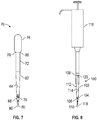
- the pipette 70 has a tube 72, a pressure mechanism 74 operably connected to the tube 72, and a capillary 76 positioned within the tube 72.
- the tube 72 may include a first end 78, a second end 80 opposite the first end 78, and a sidewall 82 extending between the first end 78 and the second end 80, The sidewall 82 completely or partially surrounds an interior cavity 84.
- the sidewall 82 of the tube 72 may extend in a straight line between the first end 78 and the second end 80. In some aspects, a first portion of the sidewall 82 of the tube 72 may extend between the first end 78 and the second end 80 at an angle with respect to a second portion of the sidewall 82 such that the first portion creates a tapered portion of the tube 72.
- the tube 72 may be transparent to light within a visible spectrum such that a user may view the contents of the interior cavity 84 through at least a portion of the sidewall 82.
- the entirety of the tube 72 may be formed from a material which is transparent to light within the visible spectrum.
- the tube 72 may be formed at least in part from polyethylene, polystyrene, polyethylene terephthaiate, polypropylene, glass, or other suitable materials.
- the pressure mechanism 74 may be operably connected to a first portion 86 of the tube 72.
- the pressure mechanism 74 may be configured to enable the liquid to be drawn or pushed into the interior cavity 84 of the tube 72.
- the pressure mechanism 74 may draw the liquid through a second portion 88 of the tube 72.
- the pressure mechanism 74 may be implemented as a bulb which may be depressed, squeezed, compressed, or otherwise manipulated to cause a partial vacuum within the tube 72. Once the second portion 88 of the tube 72 contacts the liquid, the compression or other manipulation of the pressure mechanism 74 may be released or partially released to draw at least a portion of the liquid into the interior cavity to contact the capillary 76 for temporary storage of a predefined amount of the liquid within the capillary 76.
- the capillary 76 works under the principal of capillary force in which the liquid (also referred to as "fluid” herein) contacting one of the capillary ends 89-1 and 89-2 causes capillary force that draws liquid into a bore 89-3 of the capillary 76 while bringing liquid to both of the capillary ends 89-1 and 89-2 releases the capillary force and expels the liquid.
- the liquid also referred to as "fluid” herein
- the first portion 86 of the tube 72 may be the first end 78 of the tube 72 and the second portion 88 of the tube 72 may be the second end 80 of the tube 72.
- the pressure mechanism 74 may be an air displacement member, a positive displacement member, or other suitable member capable of drawing the portion of the liquid into the interior cavity 84 of the tube 72 to contact at least one of the capillary ends.
- the pressure mechanism 74 may be integral to the tube 72 and formed as a single piece construction.
- the pressure mechanism 74 may be removably connected to the tube 72, In these aspects, after use, the tube 72 may be removed and discarded and another tube 72 may be connected to the pressure mechanism 74 to replace the discarded tube 72.
- the capillary 76 may be positioned within the interior cavity 84 of the tube 72 and in a predefined liquid path 90 between the first and second portions 86 and 88. As shown in Figure 7 , the capillary 76 may be positioned adjacent to the second portion 88 of the tube 72 generally near the second end 80 thereof.
- the capillary 76 may have a predetermined volume, for example between 1 ⁇ L and 5 ⁇ L.
- the capillary 76 may be a plurality of capillaries positioned within the interior cavity 84. In these aspects, the plurality of capillaries may be positioned around the predetermined liquid path 90 such that a portion of the sample traveling along the predefined liquid path 90 may contact the plurality of capillaries.
- the capillary 76 may be formed from plastics, glass, or other suitable materials.
- the capillary 76 may be formed from materials similar to those described with reference to the tube 12.
- the capillary 76 surrounds the bore 89-3 and is open to the surrounding atmosphere via the capillary ends 89-1 and 89-2.
- the capillary end 89-1 is positioned a first distance 94-1 from the second end 80 and the capillary end 89-2 is positioned a second distance 94-2 from the second end 80 so that liquid can be drawn through the second end 80 to contact only the capillary end 89-1 to store liquid within the bore 89-3, or to contact both the capillary ends 89-1 and 89-2 to expel the liquid from the bore 89-3.
- the second distance 94-2 is greater than the first distance 94-1 so that the capillary ends 89-1 and 89-2 can be selectively contacted with the liquid for either storing or expelling the liquid.
- the pipette 70 is also provided with a capillary holder 96 that is positioned within the interior cavity 84 and connected to the sidewall 82 and the capillary 76. As will be discussed in more detail below with reference to Figures 10-1 and 10-2 , the capillary holder 96 suspends the capillary 76 within the interior cavity 84 and permits fluid to flow past the capillary holder 96.
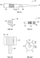
- the diluent pipette tip 100 comprises a tube 102, a capillary holder 104 positioned within the tube 102 (that is similar in construction to the capillary holder 96), and a capillary 106 positioned within the capillary holder 104.
- the tube 102 may include a first end 108, a second end 110 opposite the first end 108, and a sidewall 112 extending between the first end 108 and the second end 110 and defining an interior cavity 114.
- the first end 108 of the tube 102 may be configured to be connected to a pipette 116 such that when a sample is drawn into the pipette, the sample is drawn in a liquid path 118.
- the tube 102 may include a connection member 120 proximate to the first end 108 for connecting the tube 102 to the pipette 116.
- the connection member 120 may be a friction fit member, as shown in Figure 9-1 ; a threaded connection member, as shown in Figures 9-2 and 9-3 ; a latch member; a snap connector; or other suitable connection member capable of connecting the tube 102 to the pipette 116.
- the tube 102 may be transparent to light within a visible spectrum such that a user may view the contents of the interior cavity 114 through at least a portion of the sidewall 112.
- the entirety of the tube 102 may be formed from a material which is transparent to light within the visible spectrum.
- the tube 102 may be formed at least in part from polyethylene, polystyrene, polyethylene terephthalate, polypropylene, glass, or other suitable materials.
- the capillary holder 104 may be positioned within the interior cavity 114 of the tube 102 and in the liquid path 118.
- the capillary holder 104 may include a capillary receiving area 122 configured to receive the capillary 106 to position the capillary within the interior cavity 114 of the tube 102.
- the capillary 106 is formed integral to the capillary holder 104 as a single piece.
- the capillary holder 104 may include a plurality of capillaries or a plurality of capillary receiving areas to receive a plurality of capillaries.
- the capillary 106 or the capillary receiving area 122 may be centrally located on a center line of the interior cavity 114 extending between the first end 108 and the second end 110 of the tube 102. In some aspects, the capillary 106 may be in a coaxial relationship with the tube 102.
- the capillary holder 104 may include a body 124 and a plurality of connectors 126 extending outwardly from the body 124.
- the connectors 126 are configured to interact with the interior cavity 114 to position the capillary holder 104 proximate to the second end 110 of the tube 102 and are spaced apart to form a channel 127 between each adjacently disposed pair of connectors 126 to permit the liquid to flow past the capillary holder 104.
- the capillary holder 104 may be formed of plastics similar to those materials discussed above that can be used to form the tube 102.
- the capillary 106 may be suspended within the interior cavity 114 of the tube 102 and within the capillary holder 104 in the liquid path 118.
- the capillary 106 may have a predetermined volume.
- the capillary 106 may have a volume between 1 ⁇ L and 5 ⁇ L.
- the capillary 106 may be a plurality of capillaries suspended within the interior cavity 114 by the capillary holder 104 and may be positioned around the predetermined liquid path 118 such that a portion of the liquid traveling along the predetermined liquid path 118 may contact the plurality of capillaries.
- the capillary 106 may be formed from plastics, glass, or other suitable materials, such as those described with reference to the tube 102, for example.
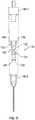
- the diluent tip 130 comprises a tube 132 and a capillary 134 positioned within the tube 131.
- the tube 132 may include a first end 136, a second end 138 opposite the first end 136, a sidewall 140 extending between the first end 136 and the second end 138 and defining an interior cavity 142.
- the tube 132 may include a first connection member 144 proximate to the first end 136 and a second connection member 146 proximate to the second end 138.
- the first connection member 144 and the second connection member 146 may be threaded connection members, friction fit connection members, or any other suitable connection members.
- the first and second connection members 144 and 146 are configured to connect the tube 132 to a needle adapter 148-1 and 148-2, respectively.
- the capillary 134 may be similar to the capillary 106, described above and may have a predetermined volume, such as between 1 ⁇ L and 5 ⁇ L, for example.
- FIG. 12 therein shown is a method for using a pipette, in accordance with some aspects of the present disclosure to perform serial dilutions with one or more diluents to form a solution.
- the method depicted in Figure 12 may be used with the pipette 70, the diluent pipette tip 100, or the diluent tip 130, for example. However, for clarity, the method will be described with reference to the pipette 70.
- the method may be performed by drawing a sample 150 of liquid/fluid into the interior cavity 84 of the pipette 70 to contact the capillary end 89-1 of the capillary 76 positioned within the interior cavity 84 such that a known volume of the sample 150 is drawn into the bore 89-3 of the capillary 76.
- the remainder of the sample 150 may be expelled from the interior cavity 84 of the pipette 70 while maintaining the known volume of the sample 150 within the capillary 76.
- a known volume of a diluent 152 may be introduced into the interior cavity 84 of the pipette 70 such that the diluent 152 contacts both of the capillary ends 89-1 and 89-2 of the capillary 76 within the interior cavity 84.
- Introducing the diluent 152 into the interior cavity 84 to contact both ends of the capillary ends 89-1 and 89-2 causes the capillary 76 to release the capillary force thereby introducing the known volume of the sample 150 into the known volume of diluent 152.
- the method may further be performed by expelling the diluted sample 156 from the interior cavity 84 of the pipette 70.
- Mixing the known volume of the diluent 152 and the known volume of the sample 150 may be performed by cycling the known volume of the diluent 152 and the known volume of the sample 150 within the interior cavity 84.
- Cycling the known volume of the diluent 152 and the known volume of the sample 150 may be performed by a combination of suction and pressure cycles applied to the interior cavity 84 of the pipette 70.
- the combination of suction and pressure cycles may be applied by partially compressing and partially decompressing the pressure mechanism 74.
- the pipette 10 and the reagent pipette tip 30 perform a function such as conducting a chemical analysis of some of the properties of a sample in an efficient and orderly fashion without having to pour the sample from a collection container into a separate test tube.
- the pipette 70, the diluent pipette tip 100, or the diluent tip 130 can be used to dilute a liquid/fluid with a single device thereby unitizing the dilution process.
- the pipette 70, the diluent pipette tip 100 and the diluent tip 130 present options for a dilution processes which can be used to increase user convenience, decrease number of disposables or ease automated operations.
- tubes 12, 32, 72, 102, and 132 can be constructed of materials that are transparent to light within the visible spectrum, it should be understood that the tubes 12, 32, 72, 102 and 132 can also (or alternatively) be transparent to light within non-visible spectrums, such as the infra-red spectrum or the ultraviolet spectrum.
Description
- This disclosure relates to pipettes for aspirating, diluting and dispensing fluids, especially samples of bodily fluids for medical diagnostic purposes.
- Pipettes are common tools used in medical diagnostic laboratories to transport measured volumes of bodily fluid samples, such as blood and urine. There are many different styles of pipettes that work by different mechanisms, most commonly piston driven pipettes and vacuum assisted pipettes. Generally, pipettes have a cylinder, graduated or not, that can be filled with a fluid using a pressure mechanism on one end of the cylinder. Disposable and single use pipettes are often made of polyethylene.
- There is a need for improved pipettes that can do more than just transfer measured volumes of sample. Specialized syringes or pipettes that can also perform a function such as conduct a chemical analysis of some of the properties of the sample or dilute a sample are the subject of the present application.
- Urinary dip strips are in common usage. Small improvements to ergonomics, handling ease and general efficiency can be very significant because so many of these manual tests are done. Samples are commonly collected from wide-mouth containers, such as cups. Fluid is then poured into a test tube (unless a very large volume of urine has been collected). A dip strip is then inserted in the test tube to contact all reactive paper pads, then it is removed and either held in the hand or placed on an absorbent paper while color develops.
- Some analytical methods require high dilution factors. Assay of Hemoglobin Alc in blood is one example. The high dilution requirement can have several reasons but a typical reason is to reduce the interference that can result from high concentration of some components other than the target of the assay. Samples are commonly serially diluted, so that a small volume is diluted with a larger one; then a small portion of this solution is subsequently diluted with a larger portion of diluent. An example is the Siemens DCA Vantage® HbA1c assay, in which a small capillary is loaded with blood sample and then positioned in a cassette and during the assay process fluid is flooded into the corner of the cassette containing the pipette. There is a need for a more simple dilution process.
-
US 6 117 394 A describes a pipette tip including a reagent-bearing filter to permit treatment of a solution passing therethrough.US 2002/110817 A1 dicloses a pipette tip connected to a pipette with a threaded connection, the pipette containing a carrier, being a porous member bearing oligonucleotides.WO 00/29112 A1 - The reagent pipette tip according to the present invention is defined in claim 1. The following disclosure describes the inventive pipette tip and related unclaimed devices and methods for illustrative purposes. In a first aspect, the disclosure includes a syringe or a pipette having a pressure mechanism operatively connected to one end of a cylinder. The cylinder includes a reagent test pad within which after reacting with a sample fluid indicates the presence or level of an analyte in a bodily fluid. The cylinder is substantially transparent or has a transparent portion which allows the result of the reagent pad to be viewed. It should be understood that the disclosure includes alternatives to a cylindrical tube where cross sections, for example rectangular or triangular, could be of a geometry most useful for the usability, economic manufacture, or robustness of the device.
- Another aspect of the disclosure relates to an improved urine dip strip. A urine dip strip, for example (Multistix® 10 SG by Siemens Healthcare Diagnostics), is inserted within a disposable pipette or syringe. The pipette functions normally with the strip inside and all reagent pads are easily contacted with sample. Color change of the reagent pads are observed through the transparent pipette material. No transfer from the original container to an intermediary tube is required. Waste may be returned immediately to the source container. The disclosure allows a reduced volume compared to standard urine dip tubes (about 2mL in the pipette vs. about 10mL in a skinny urine tube). A convenience is also realized by not having to transfer urine from a collection cup to a thin sample tube. Another convenience is that there is the option to stand the strip vertically once it has been wetted. Also, the drained pipette with strip is more rigid and accumulates less external fluid than a dipped strip. This makes its usage less messy.
- There could be several variations leading to a strip in a transparent or translucent container. In one embodiment, both ends of the tube are open to air. The squeezable portion can be squeezed, the top end of the tube may be temporarily closed, and then the squeeze released to allow fluid to be drawn in; or an external vacuum source could be applied, perhaps via syringe or pump. This configuration would allow the tube to drain by breaking the seat on the top of the tube, rather than squeezing a bulb and exuding the fluid. In another embodiment, webs or chains of tubes or pipettes with strips could be employed in an automated instrument, allowing sampling from a rack of samples, followed by automated analysis.
- A method is also disclosed including the steps of:
- ▪ aspirating fluid into a pipette containing at least one reagent pad up to a fill line;
- ▪ dispensing fluid out of the pipette; and
- ▪ reading the result of the reagent pad,
- The diagnostic indicator could be a urine strip with at least one reagent pad. Alternatively at least one reagent pad could be affixed directly to an interior portion of the tube. The fill line ensures that enough volume of sample was aspirated to cover and react with the reagent pad. The reading could be carried out in an automated manner with an analyzer such as the Clinitek Status ® analyzer (Siemens Healthcare Diagnostics) or any other camera and processor with appropriate algorithms to decode the color change of the reagent pad. It should be noted that a translucent pipette tube, such as those obtained through polyethylene molding, can still be precise for instrumental optical measurement, especially if a difference is monitored, such as color change at two different time points or as a difference in dry versus wet developed color. Alternatives to the diagnostic indicator in unitized pipette could simply divide the design into separate combinations of tip, tube, bulb and indicator unit. For example, in an automated system a strip could be allowed to fall into an optically clear rectangular chamber with a tip which is a ported cone or hollow needle. Replacement of the bulb with another mechanism for aspiration and dispense is consistent with the disclosure.
- Another aspect of the disclosure is a pipette which unitizes the dilution process. A capillary of defined small volume is positioned within a pipette tip using a small holder for the capillary. This holder could be integrated into the molded pipette tip or other affixed therein. The disclosure presents options for a dilution processes which can be used to increase user convenience, decrease number of disposables or ease automated operations. Though the capillary could be mounted in a pipette with squeezable integrated bulb, the preferred design is based upon dimensions for a pipette tip of a type meant for common handheld laboratory pipettors (supplying the air seal and pressure/vacuum for fluid transfers). These same tips are used in instrument or robotic dilution systems. The configuration of the demonstrated disclosure should be fully usable in either manual or automated methods. The secured capillary may also be enclosed in a tube which bridges the aspiration/dispense device and a common pipette tip or needle. This variation may be more versatile or economic for automated, high throughput systems, where use of mass-produced components such as a tip or a needle is an advantage.
- Another aspect of the disclosure is that dilutions could be done serially. At the end of the first cycle of dilution, the capillary in the empty pipette tip contains diluted solute in solution, introduction of a new load of diluent can produce a further dilution of the solution without having to change pipette tips. The HbA1c assay is one of the immunoassays that performs best with precise, high dilution of sample. By adding the microcapillary used in the present disclosure to a pipette tip, it becomes possible to make precise dilutions using the dispenser. Sample can be drawn into contact with the capillary and excess expelled. Diluent can be brought in from the top or also drawn up, so that it surrounds the capillary. Small suction/pressure cycles can be used to mix the capillary contents with the tip fluid and all or part of the total fluid expelled for use as a diluted sample.
- An exemplary method includes:
- ▪ 50 microliter dye + water, capillary fills;
- ▪ fluid expelled, capillary holds full small volume;
- ▪ 80 microliter diluent water taken in + 20 microliter air. Concentrated dye moves out of capillary, mixed, capillary refilled and fluid expelled;
- ▪ Repeat with more diluent as necessary;
- ▪ capillary has diluted fluid inside;
- ▪ Capillary fluid is expelled
- The capillary may be expelled by bringing fluid to both its ends, thereby releasing the capillary force. Fluid is held tightly in a capillary when the ends have at least one fluid/air interface, but when both ends have a fluid/fluid interface (if both hydrophilic) then capillary action is lost and the contents of the capillary migrate easily. The pipette may include assortments of combinations in sizes of capillaries and pipette tips or multiple capillaries within the tip. The pipette may be used for mixing solutions for chemical reaction, or for reacting to fluids where the second load of diluent contains chemicals which are reactive with those of the first dilution. The pipette tip may be long and have capillaries positioned along the interior length of the pipette with a defined distance between them, and fluid is caused to mix in stages as it is drawn up the pipette tip. The fluid may be expelled and replaced with a different fluid which is caused to move to upper capillaries. Another embodiment includes a capillary containing a dried or lyophilized or encapsulated substance to be diluted.
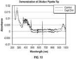
- Example: The strip/pipette solution of the present invention disclosure was used to do a spectroscopic demonstration of function. A 2 microliter portion of the stock was mixed with 98 microL of water as a control and the water blanked spectrum taken in a 1mL quartz cuvette on an HP 8453 spectrophotometer. A dilution tip was assembled using one of the holders of the present invention disclosure. Using a 100 microL microliter Rainien pipettor, a 50 microliter portion of the stock was taken into the tip to just contact the capillary end and then was expelled. All of the air was expelled and an 80 microliter portion of water was taken in, completely immersing the capillary and internal holder. The pipettor dial was adjusted to 100 in air, pulling in about 30microL air. The pipettor plunger was depressed partly and released several times to allow fluids to mix. The 80+ microliter contents were expelled into 920 microliter water and mixed and the spectrum taken. As shown in
Figure 13 , the spectra were very similar, showing a similar dilution (50 fold) was attained. - In some aspects, the present disclosure describes a pipette having a tube, a pressure mechanism and at least one reagent pad. The tube has a sidewall defining an interior cavity. The pressure mechanism is operably connected to the tube. The pressure mechanism is configured to enable a sample to be drawn into the interior cavity of the tube through an opening of the tube. The at least one reagent pad is positioned in the interior cavity of the tube and within a predefined liquid path whereby a sample contacts at least a portion of the at least one reagent pad when drawn into the interior cavity.
- In some aspects, the present disclosure describes a reagent pipette tip having a tube, and at least one reagent pad. The tube has a first end, a second end opposite the first end, and a sidewall extending between the first end and the second end defining an interior cavity. A portion of the tube is configured to be connected to a pipette such that when a sample is drawn into the pipette, the sample is drawn through the tube in a liquid path. The at least one reagent pad is positioned within the interior cavity of the tube and in the liquid path whereby a sample contacts at least a portion of the at least one reagent pad when drawn into the interior cavity.
- In some aspects, the present disclosure describes a pipette having a tube, a pressure mechanism and a capillary. The tube has a first end, a second end opposite the first end, and a sidewall extending between the first end and the second end. The sidewall defines an interior cavity. The pressure mechanism is operably connected to a first portion of the tube. The pressure mechanism is configured to enable a sample to be drawn into the interior cavity of the tube through a second portion of the tube. The capillary is positioned within the interior cavity of the tube between the first portion and the second portion and in a predefined liquid path between the first and second portions.
- In some aspects the present disclosure describes a diluent pipette tip having a tube, a capillary holder and a capillary. The tube has a first end, a second end opposite the first end, and a sidewall extending between the first end and the second end defining an interior cavity. A connection member of the tube is configured to be connected to a pipette such that when a sample is drawn into the pipette, the sample is drawn in a liquid path through the tube. The capillary holder is positioned within the interior cavity of the tube and in the liquid path, the capillary holder has a capillary receiving area and one or more connection members extending outwardly from the capillary receiving area towards the sidewall of the tube. The capillary is positioned within the capillary receiving area and in the liquid path.
- In some aspects the present disclosure describes a diluent tip having a tube and a capillary. The tube has a first end, a second end opposite the first end, a sidewall extending between the first end and the second end defining an interior cavity and a connection member configured to connect the tube to a pipette. The capillary is suspended within the interior cavity such that a fluid passing through the interior cavity contacts one or more capillary ends of the capillary.
- In some aspects, the present disclosure describes a method. In such method, a sample of fluid is transferred (e.g., drawn) into an interior cavity of a tube of a pipette such that the sample is in contact with at least a portion of at least one reagent pad positioned within the interior cavity of the pipette. The sample is expelled from the interior cavity of the pipette, and a result is read through the tube of the pipette.
- In some aspects, the present disclosure describes a method in which a fluid is transferred (e.g., drawn) into an interior cavity of a pipette to contact a first capillary end of a capillary and avoid a second capillary end of the capillary such that a known volume of the fluid is drawn into the capillary by a capillary force. The fluid is expelled from the interior cavity of the pipette while maintaining the known volume of the fluid within the capillary. A known volume of a diluent is introduced into the interior cavity of the pipette such that the diluent contacts the first and second capillary ends of the capillary within the interior cavity whereby the known volume of the diluent and the known volume of the sample mix to form a diluted sample, and the diluted sample is expelled from the interior cavity of the pipette.
- A more complete appreciation of the present disclosure and many of the attendant advantages thereof will be readily understood by reference to the following detailed description when taken in conjunction with the accompanying drawings, in which:
-
Figure 1 is a side elevational view of a pipette in accordance with the invention. -
Figure 2 shows an elevational view of the pipette ofFigure 1 with a removable tip portion, in accordance with the invention. -
Figure 3 shows diagrammatic depiction of a method for inserting a reagent pad into the pipette ofFigure 1 . -
Figure 4-1 - 4-4 show a reagent pipette tip in accordance with some aspects of the present disclosure:-
Figure 4-1 shows an exploded view of a reagent pipette tip with a reagent pad, in accordance with some aspects of the present disclosure; -
Figure 4-2 shows a top plan view of the reagent pipette tip ofFigure 4-1 taken along line 4-2; -
Figure 4-3 shows a side elevational view of the reagent pipette tip and the reagent pad ofFigure 4-1 ; and -
Figure 4-4 shows a side elevational view of a pipette assembly comprising the reagent pipette tip ofFigure 4-1 connected to a pipette.
-
-
Figure 5 shows a diagrammatic method depicting the pipette ofFigure 1 in use to wet reagent pads within the pipette with a sample. -
Figure 6 shows another aspect of the diagrammatic method ofFigure 5 in which the sample is expelled from the pipette. -
Figure 7 shows a side elevational view of a pipette in accordance with some aspects of the present disclosure. -
Figure 8 shows a side elevational view of a diluent pipette tip, in accordance with some espects of the present disclosure connected to a pipette. -
Figure 9-1 - 9-3 show aspects of the diluent pipette tip ofFigure 8 :-
Figure 9-1 shows a side elevational view of the diluent pipette tip ofFigure 8 with a friction fit connector; -
Figure 9-2 shows a top plan view of the diluent pipette tip ofFigure 8 with a threaded connector; and -
Figure 9-3 shows a perspective view of the diluent pipette tip ofFigure 9-2 .
-
-
Figures 10-1 and 10-2 show a capillary holder and capillary in accordance with some aspects of the present disclosure:-
Figure 10-1 shows a side elevational view of a capillary holder and a capillary in accordance with the present disclosure; and -
Figure 10-2 shows a top plan view of the capillary holder and the capillary ofFigure 10-1 .
-
-
Figure 11 shows an exploded view of a diluent tip with a needle adapter in accordance with some aspects of the present disclosure. -
Figure 12 shows a method of using the pipette ofFigure 7 , in accordance with some aspects of the present disclosure. -
Figure 13 is a graph showing a spectra obtained from a spectroscopic demonstration of a control sample and a sample produced with the method depicted inFigure 12 . - Specific aspects disclosed herein will now be described in detail with reference to the accompanying drawings. Further, in the following detailed description of aspects of the present disclosure, numerous specific details are set forth in order to provide a more thorough understanding of the disclosure. However, it will be apparent to one of ordinary skill in the art that the embodiments disclosed herein may be practiced without these specific details. In other instances, well-known features have not been described in detail to avoid unnecessarily complicating the description.
- Unless expressly stated to the contrary, "or" refers to an inclusive or and not to an exclusive or. For example, a condition A or B is satisfied by anyone of the following: A is true (or present) and B is false (or not present), A is false (or not present) and B is true (or present), and both A and B are true (or present).
- In addition, use of the "a" or "an" are employed to describe elements and components of the embodiments herein. This is done merely lor convenience and to give a general sense of the inventive concept. This description should be read to include one or at least one and the singular also includes the plural unless otherwise stated.
- The terminology and phraseology used herein is for descriptive purposes and should not be construed as limiting in scope. Language such as "including," "comprising," "having," "containing," or "involving," and variations thereof, is intended to be broad and encompass the subject matter listed thereafter, equivalents, and additional subject matter not recited or inherently present therein.
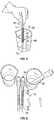
- Referring now to
Figure 1 , therein shown is apipette 10 in accordance with some embodiments of the invention. Thepipette 10 comprises atube 12, apressure mechanism 14 operably connected and sealed to thetube 12, and at least onereagent pad 16 positioned in thetube 12. Thetube 12 may include afirst end 18 connected to thepressure mechanism 14, asecond end 20 opposite thefirst end 18, and asidewall 22 extending between thefirst end 18 and thesecond end 20. Thesidewall 22 may define aninterior cavity 24 with thefirst end 18 and thesecond end 20 being open. In some embodiments, at least a portion of thetube 12 may extend adjacent to the at least onereagent pad 16. For example, in some embodiments, thesidewall 22 of thetube 12 may extend in a straight line, substantially parallel to the at least onereagent pad 16 between thefirst end 18 and thesecond end 20. In some embodiments, one or more portion of thesidewall 22 may extend between thefirst end 18 and thesecond end 20 at an angle relative to the at least onereagent pad 16 causing the at least a portion of thetube 12 to taper or enlarge between thefirst end 18 and thesecond end 20. In some embodiments, the portion of thetube 12 which tapers may serve to limit movement of the at least onereagent pad 16 within theinterior cavity 24 and to position the at least onereagent pad 16 within theinterior cavity 24. - In some embodiments, the
tube 12 may be transparent to light within a visible spectrum such that a user may view the contents of theinterior cavity 24 through at least a portion of thesidewall 22. In some embodiments, as shown inFigure 1 , the entirety of thetube 12 may be formed from a material which is transparent to light within the visible spectrum. For example, in some embodiments, thetube 12 may be formed at least in part from polyethylene, polystyrene, polyethylene terephthalate, polypropylene, glass, or other suitable materials. In the reagent pipette tip according to the invention, as shown inFigure 2 , atip portion 25 is removably connected to thetube 12 proximate to thesecond end 20 of thetube 12. Thetip portion 25 may be removed to permit the sample to be drawn into thetube 12, or for insertion of the at least onereagent pad 16 into theinterior cavity 24 of thetube 12. In some embodiments, thetip portion 25 may be reconnected to thetube 12 after insertion of the at least onereagent pad 16 into theinterior cavity 24 of thetube 12. - The
pressure mechanism 14 is operably connected to thefirst end 18 of thetube 12 and is adapted to supply pressure/vacuum to thetube 12 suitable for fluid transfers. In some embodiments, thepressure mechanism 14 may be configured to create a pressure differential which causes a sample to be drawn into the interior cavity of thetube 12 through thesecond end 20 of thetube 12. In some embodiments, thepressure mechanism 14 may be implemented as a bulb 14-1 constructed of an elastomeric material having a squeezable portion and operably connected to thefirst end 18 of thetube 12 to cause a partial vacuum when released. In these embodiments, the bulb 14-1 may depressed, squeezed, compressed, or otherwise manipulated to cause a partial vacuum at thefirst end 18 of thetube 12. Once thesecond end 20 of thetube 12 is placed in the sample, the compression or other manipulation of the bulb 14-1 may be released to create the partial vacuum and thereby draw at least a portion of the sample into theinterior cavity 24 of thetube 12. In some embodiments, such as when thepressure mechanism 14 is implemented as a bulb, thepressure mechanism 14 may include a pressure release hole (not shown) enabling sample contained within thepressure mechanism 14 or theinterior cavity 24 to be released. In use, the pressure release hole may be covered when thepressure mechanism 14 is manipulated to draw the sample into the interior cavity, thereby enabling a partial vacuum within thetube 12. The pressure release hole may then be uncovered to release the partial vacuum and thereby expel the sample out of theinterior cavity 24 and/or thepressure mechanism 14. - In some embodiments, the
pressure mechanism 14 may be an external vacuum source, such as a pump including an air displacement member, a positive displacement member, or other suitable member capable of drawing the sample fluid into theinterior cavity 24 of thetube 12. In some embodiments, thepressure mechanism 14 may be integral to thetube 12 and formed as a single piece construction. In some embodiments, thepressure mechanism 14 may be removably connected to thetube 12. In these embodiments, after use, thetube 12 may be removed and discarded and anothertube 12 may be connected to thepressure mechanism 14 to replace the discardedtube 12. - The at least one
reagent pad 16 may be aligned and positioned on asubstrate 26 of atest strip 28. The at least onereagent pad 16 is positioned in theinterior cavity 24 of thetube 12. In some embodiments, the at least onereagent pad 16 may be positioned within a predefined liquid path within theinterior cavity 24 whereby the sample contacts at least a portion of the at least onereagent pad 16 when drawn into theinterior cavity 24. In some embodiments, the at least onereagent pad 16 may be affixed directly to an interior portion of thetube 12. In other embodiments, the at least onereagent pad 16 may be removable from theinterior cavity 24 such that thetube 12 and thepressure mechanism 14 of thepipette 10 may be reused after thetube 12 and thepressure mechanism 14 have been cleaned and a new at least onereagent pad 16 has been positioned within theinterior cavity 24. - Referring now to
Figure 3 , therein shown is a method of positioning the at least onereagent pad 16 into theinterior cavity 24 of thetube 12, in accordance with some aspects of the present disclosure. As discussed below, thesidewall 22 of thetube 12 may be formed of an elastomeric material having a generally circular cross-section to facilitate the position of the at least onereagent pad 16 into theinterior cavity 24. To position the at least onereagent pad 16 into theinterior cavity 24 of thetube 12, thetip portion 25 is removed from thetube 12. Once thetip portion 25 is removed, thetube 12 is compressed near thesecond end 20 to cause a deformation of thetube 12 into an oval shape thereby laterally expanding thesecond end 20 of thetube 12. In at least some embodiments, the deformation and lateral expansion of thetube 12 andinterior cavity 24 may be temporary, lasting only during the compression of thetube 12. The at least onereagent pad 16 may be inserted into thesecond end 20 of the tube 12 (which is open), thereby positioning the at least onereagent pad 16 into theinterior cavity 24. Thetube 12 is then released from the compression thereby allowing thetube 12 to assume its original circular shape and securing the at least onereagent pad 16 within theinterior cavity 24. Once the at least onereagent pad 16 is positioned within theinterior cavity 24, thetip portion 25 can be re-attached to thesecond end 20 of thetube 12. - In some aspects, where the
side wail 22 of thetube 12 is not tapered prior to thetip portion 25, the at least onereagent pad 16 may be removed without compression of thetube 12. In some aspects, thepressure mechanism 14 may be removed from thetube 12 and the at least onereagent pad 16 inserted and/or removed through thefirst end 18. - Referring now to
Figures 4-1 - 4-4 , therein shown is areagent pipette tip 30, according to some aspects of the present disclosure. Thereagent pipette tip 30 may comprise atube 32 and at least onereagent pad 34 positioned within thetube 32. Thetube 32 may have afirst end 36, asecond end 38 opposite thefirst end 36, and asidewall 40 extending between thefirst end 36 and thesecond end 38 defining aninterior cavity 42. Thefirst end 36 of thetube 32 may be configured to be connected to apipette 44 such that when a sample is drawn into thepipette 44, the sample is drawn through thetube 32 in a predefinedliquid path 46. In some aspects, thesidewall 40 may extend adjacent to theliquid path 46 and the at least onereagent pad 34. In some embodiments, at least a portion of thetube 32 may taper, similar to thetube 12. For example, as shown inFigures 4-1, 4-3, and 4-4 , thesidewall 40 of thetube 32 may taper proximate to thesecond end 38 of thetube 32. - In some aspects, the
sidewall 40 of thetube 32 may be provided with ashoulder 48 within theinterior cavity 42 and proximate to thesecond end 38. In these aspects, theshoulder 48 may be configured to position the at least onereagent pad 34 within theinterior cavity 42 and limit movement of the at least onereagent pad 34 within theinterior cavity 42. - In some aspects, the
tube 32 may include a connection member 50 proximate to thefirst end 36 for connecting thetube 32 to thepipette 44. In some aspects, the connection member 50 may be a threaded connection member, snap connector, a latch, a friction fit, or other suitable connector to secure thereagent pipette tip 30 to thepipette 44. In the example shown, the connection member 50 is internal threads formed adjacent to thefirst end 36 of thetube 32. - In some aspects the
tube 32 may be transparent to light within a visible spectrum such that a user (and/or an optical reader of an analyzer) may view the contents of theinterior cavity 42 through at least a portion of thesidewall 40. In some embodiments, as shown inFigure 4-1, 4-3, and 4-4 , the entirety of thetube 32 may be formed from a material which is transparent to light within the visible spectrum. For example, in some aspects thetube 32 may be formed at least in part from polyethylene, polystyrene, polyethylene terephthalate, polypropylene, glass, or other suitable materials. - The at least one
reagent pad 34 may be implemented similarly to thereagent pad 16, e.g., positioned on asubstrate 52 and aligned on thesubstrate 52 to form atest strip 54. The at least onereagent pad 34 is positioned in theinterior cavity 42 of thetube 32 in theliquid path 46 whereby the sample contacts at least a portion of the at least onereagent pad 34 when drawn into theinterior cavity 42. - The
pipette 44 may be any pipette capable of receiving and/or being connected to a replaceable tip section. For example, thepipette 44 may be an automated pipette connected to a machine with a plurality of other pipettes, an air displacement pipette, a bulb pipette, a positive displacement pipette, a triggered automatic propipetter, or a button operated automatic propipetter, for example. - Referring now to
Figures 5 and 6 , shown therein is a method of using thepipette 10, in accordance with some aspects of the present disclosure. The method shown inFigures 5 and 6 may also be applicable to thereagent pipette tip 30, when connected to thepipette 44. For clarity, the method will be described with reference to thepipette 10. The method may be performed by drawing asample 60 of fluid into theinterior cavity 24 of thetube 12 of thepipette 10 such that the sample is in contact with at least a portion of the at least onereagent pad 16 positioned within theinterior cavity 24 of thepipette 10. Thesample 60 may be drawn into theinterior cavity 24 by actuating thepressure mechanism 14. For example, by compressing thepressure mechanism 14, when implemented as a bulb, placing thesecond end 20 of thetube 12 into the fluid and releasing compression on thepressure mechanism 14, thereby creating a partial vacuum within thetube 12 and drawing thesample 60 into theinterior cavity 24. The method may further be performed by expelling thesample 60 from theinterior cavity 24 of thepipette 10 and reading a result one or more times through thetube 12 of thepipette 10. When more than one reading of the result is taken, the readings can be taken at predetermined time periods such as between 1-3 minutes after the at least onereagent pad 16 has been whetted by thesample 60. - In some aspects, as shown in
Figure 6 , the result is read on the at least onereagent pad 16 through a transparent portion of thepipette 10, where at least a portion of thetube 12 of thepipette 10 is transparent to light in the visible portion of the light spectrum. The result may be a change in color of the at least onereagent pad 16. Where a plurality of reagent pads is positioned within theinterior cavity 24 and contact thesample 60, the plurality of reagent, pads may provide one or more results, for example, by testing for discrete properties or components within thesample 60. In some aspects the at least onereagent pad 16 may include one or more component mixable with the sample when the sample contacts the at least onereagent pad 16. In these aspects, the result may be a change in a property of thesample 60 expelled from or retained within theinterior cavity 24 of thepipette 10. The property may be a color, or an electrical property such as conductivity. - Referring now to
Figure 7 , shown therein is apipette 70 in accordance with some aspects of the present disclosure which can be used to dilute a liquid as will be described below. The liquid can be a sample of bodily fluid from a mammal, a reagent, or any other substance in a liquid form. Thepipette 70 has atube 72, apressure mechanism 74 operably connected to thetube 72, and a capillary 76 positioned within thetube 72. Thetube 72 may include afirst end 78, asecond end 80 opposite thefirst end 78, and asidewall 82 extending between thefirst end 78 and thesecond end 80, Thesidewall 82 completely or partially surrounds aninterior cavity 84. In some aspects, thesidewall 82 of thetube 72 may extend in a straight line between thefirst end 78 and thesecond end 80. In some aspects, a first portion of thesidewall 82 of thetube 72 may extend between thefirst end 78 and thesecond end 80 at an angle with respect to a second portion of thesidewall 82 such that the first portion creates a tapered portion of thetube 72. - In some aspects, the
tube 72 may be transparent to light within a visible spectrum such that a user may view the contents of theinterior cavity 84 through at least a portion of thesidewall 82. In some embodiments, the entirety of thetube 72 may be formed from a material which is transparent to light within the visible spectrum. For example, in some embodiments, thetube 72 may be formed at least in part from polyethylene, polystyrene, polyethylene terephthaiate, polypropylene, glass, or other suitable materials. - The
pressure mechanism 74 may be operably connected to afirst portion 86 of thetube 72. Thepressure mechanism 74 may be configured to enable the liquid to be drawn or pushed into theinterior cavity 84 of thetube 72. For example, thepressure mechanism 74 may draw the liquid through asecond portion 88 of thetube 72. In some aspects, thepressure mechanism 74 may be implemented as a bulb which may be depressed, squeezed, compressed, or otherwise manipulated to cause a partial vacuum within thetube 72. Once thesecond portion 88 of thetube 72 contacts the liquid, the compression or other manipulation of thepressure mechanism 74 may be released or partially released to draw at least a portion of the liquid into the interior cavity to contact the capillary 76 for temporary storage of a predefined amount of the liquid within thecapillary 76. As discussed above, the capillary 76 works under the principal of capillary force in which the liquid (also referred to as "fluid" herein) contacting one of the capillary ends 89-1 and 89-2 causes capillary force that draws liquid into a bore 89-3 of the capillary 76 while bringing liquid to both of the capillary ends 89-1 and 89-2 releases the capillary force and expels the liquid. Liquid is held tightly in the bore 89-3 of the capillary 76 when the capillary ends 89-1 and 89-2 have at least one liquid air interface, but when both capillary ends 89-1 and 89-2 have a liquid/liquid interface (if both hydrophilic) then capillary action is lost and the contents within the bore 89-3 of the capillary 76 migrate easily. In some aspects, thefirst portion 86 of thetube 72 may be thefirst end 78 of thetube 72 and thesecond portion 88 of thetube 72 may be thesecond end 80 of thetube 72. - In some aspects, the
pressure mechanism 74 may be an air displacement member, a positive displacement member, or other suitable member capable of drawing the portion of the liquid into theinterior cavity 84 of thetube 72 to contact at least one of the capillary ends. In some aspects, thepressure mechanism 74 may be integral to thetube 72 and formed as a single piece construction. In some aspects, thepressure mechanism 74 may be removably connected to thetube 72, In these aspects, after use, thetube 72 may be removed and discarded and anothertube 72 may be connected to thepressure mechanism 74 to replace the discardedtube 72. - The capillary 76 may be positioned within the
interior cavity 84 of thetube 72 and in a predefinedliquid path 90 between the first andsecond portions Figure 7 , the capillary 76 may be positioned adjacent to thesecond portion 88 of thetube 72 generally near thesecond end 80 thereof. The capillary 76 may have a predetermined volume, for example between 1 µL and 5 µL. In some aspects, the capillary 76 may be a plurality of capillaries positioned within theinterior cavity 84. In these aspects, the plurality of capillaries may be positioned around the predeterminedliquid path 90 such that a portion of the sample traveling along the predefinedliquid path 90 may contact the plurality of capillaries. The capillary 76 may be formed from plastics, glass, or other suitable materials. For example, the capillary 76 may be formed from materials similar to those described with reference to thetube 12. The capillary 76 surrounds the bore 89-3 and is open to the surrounding atmosphere via the capillary ends 89-1 and 89-2. The capillary end 89-1 is positioned a first distance 94-1 from thesecond end 80 and the capillary end 89-2 is positioned a second distance 94-2 from thesecond end 80 so that liquid can be drawn through thesecond end 80 to contact only the capillary end 89-1 to store liquid within the bore 89-3, or to contact both the capillary ends 89-1 and 89-2 to expel the liquid from the bore 89-3. The second distance 94-2 is greater than the first distance 94-1 so that the capillary ends 89-1 and 89-2 can be selectively contacted with the liquid for either storing or expelling the liquid. - The
pipette 70 is also provided with a capillary holder 96 that is positioned within theinterior cavity 84 and connected to thesidewall 82 and the capillary 76. As will be discussed in more detail below with reference toFigures 10-1 and 10-2 , the capillary holder 96 suspends the capillary 76 within theinterior cavity 84 and permits fluid to flow past the capillary holder 96. - Referring now to
Figures 8 ,9-1 - 9-3, and 10-1 - 10-2 , therein shown is adiluent pipette tip 100, according to some aspects of the present disclosure. Thediluent pipette tip 100 comprises atube 102, acapillary holder 104 positioned within the tube 102 (that is similar in construction to the capillary holder 96), and a capillary 106 positioned within thecapillary holder 104. Thetube 102 may include afirst end 108, asecond end 110 opposite thefirst end 108, and asidewall 112 extending between thefirst end 108 and thesecond end 110 and defining aninterior cavity 114. Thefirst end 108 of thetube 102 may be configured to be connected to apipette 116 such that when a sample is drawn into the pipette, the sample is drawn in aliquid path 118. As shown inFigures 8 and9-1 , thetube 102 may include aconnection member 120 proximate to thefirst end 108 for connecting thetube 102 to thepipette 116. Theconnection member 120 may be a friction fit member, as shown inFigure 9-1 ; a threaded connection member, as shown inFigures 9-2 and 9-3 ; a latch member; a snap connector; or other suitable connection member capable of connecting thetube 102 to thepipette 116. - In some aspects the
tube 102 may be transparent to light within a visible spectrum such that a user may view the contents of theinterior cavity 114 through at least a portion of thesidewall 112. In some aspects, the entirety of thetube 102 may be formed from a material which is transparent to light within the visible spectrum. For example, in some embodiments, thetube 102 may be formed at least in part from polyethylene, polystyrene, polyethylene terephthalate, polypropylene, glass, or other suitable materials. - The
capillary holder 104, as shown inFigures 8 ,10-1, and 10-2 , may be positioned within theinterior cavity 114 of thetube 102 and in theliquid path 118. In some aspects, thecapillary holder 104 may include acapillary receiving area 122 configured to receive the capillary 106 to position the capillary within theinterior cavity 114 of thetube 102. In some aspects, the capillary 106 is formed integral to thecapillary holder 104 as a single piece. In some embodiments, thecapillary holder 104 may include a plurality of capillaries or a plurality of capillary receiving areas to receive a plurality of capillaries. In some embodiments, the capillary 106 or thecapillary receiving area 122 may be centrally located on a center line of theinterior cavity 114 extending between thefirst end 108 and thesecond end 110 of thetube 102. In some aspects, the capillary 106 may be in a coaxial relationship with thetube 102. Thecapillary holder 104 may include abody 124 and a plurality ofconnectors 126 extending outwardly from thebody 124. Theconnectors 126 are configured to interact with theinterior cavity 114 to position thecapillary holder 104 proximate to thesecond end 110 of thetube 102 and are spaced apart to form a channel 127 between each adjacently disposed pair ofconnectors 126 to permit the liquid to flow past thecapillary holder 104. Thecapillary holder 104 may be formed of plastics similar to those materials discussed above that can be used to form thetube 102. - The capillary 106 may be suspended within the
interior cavity 114 of thetube 102 and within thecapillary holder 104 in theliquid path 118. The capillary 106 may have a predetermined volume. For example, the capillary 106 may have a volume between 1 µL and 5 µL. In some aspects, the capillary 106 may be a plurality of capillaries suspended within theinterior cavity 114 by thecapillary holder 104 and may be positioned around the predeterminedliquid path 118 such that a portion of the liquid traveling along the predeterminedliquid path 118 may contact the plurality of capillaries. The capillary 106 may be formed from plastics, glass, or other suitable materials, such as those described with reference to thetube 102, for example. - Referring now to
Figure 11 , therein shown is adiluent tip 130, according to some aspects of the present disclosure. Thediluent tip 130 comprises atube 132 and a capillary 134 positioned within the tube 131. Thetube 132 may include afirst end 136, asecond end 138 opposite thefirst end 136, asidewall 140 extending between thefirst end 136 and thesecond end 138 and defining aninterior cavity 142. Thetube 132 may include afirst connection member 144 proximate to thefirst end 136 and asecond connection member 146 proximate to thesecond end 138. Thefirst connection member 144 and thesecond connection member 146 may be threaded connection members, friction fit connection members, or any other suitable connection members. In some embodiments, the first andsecond connection members tube 132 to a needle adapter 148-1 and 148-2, respectively, The capillary 134 may be similar to the capillary 106, described above and may have a predetermined volume, such as between 1 µL and 5 µL, for example. - Referring now to
Figure 12 , therein shown is a method for using a pipette, in accordance with some aspects of the present disclosure to perform serial dilutions with one or more diluents to form a solution. The method depicted inFigure 12 may be used with thepipette 70, thediluent pipette tip 100, or thediluent tip 130, for example. However, for clarity, the method will be described with reference to thepipette 70. The method may be performed by drawing asample 150 of liquid/fluid into theinterior cavity 84 of thepipette 70 to contact the capillary end 89-1 of the capillary 76 positioned within theinterior cavity 84 such that a known volume of thesample 150 is drawn into the bore 89-3 of the capillary 76. The remainder of thesample 150 may be expelled from theinterior cavity 84 of thepipette 70 while maintaining the known volume of thesample 150 within thecapillary 76. A known volume of a diluent 152 may be introduced into theinterior cavity 84 of thepipette 70 such that the diluent 152 contacts both of the capillary ends 89-1 and 89-2 of the capillary 76 within theinterior cavity 84. Introducing the diluent 152 into theinterior cavity 84 to contact both ends of the capillary ends 89-1 and 89-2 causes the capillary 76 to release the capillary force thereby introducing the known volume of thesample 150 into the known volume ofdiluent 152. The method may further be performed by expelling the diluted sample 156 from theinterior cavity 84 of thepipette 70. Mixing the known volume of the diluent 152 and the known volume of thesample 150 may be performed by cycling the known volume of the diluent 152 and the known volume of thesample 150 within theinterior cavity 84. Cycling the known volume of the diluent 152 and the known volume of thesample 150 may be performed by a combination of suction and pressure cycles applied to theinterior cavity 84 of thepipette 70. For example, the combination of suction and pressure cycles may be applied by partially compressing and partially decompressing thepressure mechanism 74. - In light of the foregoing, one skilled in the art will understand that the presently disclosed pipettes are an advance over known pipettes. With respect to the embodiments of
Figures 1-6 , thepipette 10 and thereagent pipette tip 30 perform a function such as conducting a chemical analysis of some of the properties of a sample in an efficient and orderly fashion without having to pour the sample from a collection container into a separate test tube. With respect to the aspects ofFigures 7-12 , thepipette 70, thediluent pipette tip 100, or thediluent tip 130 can be used to dilute a liquid/fluid with a single device thereby unitizing the dilution process. Thepipette 70, thediluent pipette tip 100 and thediluent tip 130 present options for a dilution processes which can be used to increase user convenience, decrease number of disposables or ease automated operations. - Further, although the
tubes tubes
Claims (2)
- A reagent pipette tip, comprising:a tube (12) having a first end (18), a second end (20) opposite the first end (18), and a sidewall (22) extending between the first end (18) and the second end (20) defining an interior cavity (24), a portion of the tube (12) being configured to be connected to a pipette (10) such that when a sample is drawn into the pipette, the sample is drawn through the tube in a liquid path; andat least one reagent pad (16) positioned within the interior cavity (24) of the tube and in the liquid path whereby a sample contacts at least a portion of the at least one reagent pad (16) when drawn into the interior cavity (24),wherein the reagent pipette tip further comprises a pressure mechanism (14) operably connected to the first end (18) of the tube (12); andcharacterized in that a tip portion (25) is removably connected to the tube (12) proximate to the second end (20) of the tube (12).
- The reagent pipette tip of claim 1, wherein at least the portion of the tube (12) is transparent to light within a visible spectrum.
Applications Claiming Priority (2)
| Application Number | Priority Date | Filing Date | Title |
|---|---|---|---|
| US201361803629P | 2013-03-20 | 2013-03-20 | |
| PCT/US2014/030948 WO2014153308A2 (en) | 2013-03-20 | 2014-03-18 | Pipette components useful for medical diagnostics |
Publications (3)
| Publication Number | Publication Date |
|---|---|
| EP2976151A2 EP2976151A2 (en) | 2016-01-27 |
| EP2976151A4 EP2976151A4 (en) | 2017-03-22 |
| EP2976151B1 true EP2976151B1 (en) | 2019-05-01 |
Family
ID=51581786
Family Applications (1)
| Application Number | Title | Priority Date | Filing Date |
|---|---|---|---|
| EP14770970.3A Active EP2976151B1 (en) | 2013-03-20 | 2014-03-18 | Pipette tip containing reagent pad |
Country Status (3)
| Country | Link |
|---|---|
| US (2) | US20160288118A1 (en) |
| EP (1) | EP2976151B1 (en) |
| WO (1) | WO2014153308A2 (en) |
Families Citing this family (6)
| Publication number | Priority date | Publication date | Assignee | Title |
|---|---|---|---|---|
| GB201400115D0 (en) * | 2014-01-05 | 2014-02-19 | Gerardos Georgios | Multiple ligands detection using an immunoassay device |
| US10018536B2 (en) * | 2015-04-21 | 2018-07-10 | Saint-Gobain Performance Plastics Corporation | Small volume sampling device |
| EP3905787A1 (en) | 2016-06-21 | 2021-11-03 | Guangdong Oppo Mobile Telecommunications Corp., Ltd. | Multiple synchronization signals in a single transmission period |
| US11280805B2 (en) * | 2018-06-05 | 2022-03-22 | Chemthief, Llc | Robot device for collection of solid, liquid and/or multiphase samples |
| CN108507860A (en) * | 2018-06-19 | 2018-09-07 | 江苏科华医疗器械科技有限公司 | A kind of novel all-in-one sample diluting device |
| CN111956851B (en) * | 2020-08-25 | 2023-06-09 | 郑州金域临床检验中心有限公司 | Full-automatic pipettor disinfection device and application method thereof |
Family Cites Families (20)
| Publication number | Priority date | Publication date | Assignee | Title |
|---|---|---|---|---|
| US4309912A (en) * | 1980-08-01 | 1982-01-12 | Smith Kendall O | Micro-analysis process and device |
| US5387526A (en) * | 1990-09-11 | 1995-02-07 | General Atomics | Coated capillary tube for the controlled release of reagent |
| US6660233B1 (en) * | 1996-01-16 | 2003-12-09 | Beckman Coulter, Inc. | Analytical biochemistry system with robotically carried bioarray |
| US6117394A (en) * | 1996-04-10 | 2000-09-12 | Smith; James C. | Membrane filtered pipette tip |
| US6197259B1 (en) * | 1998-11-06 | 2001-03-06 | Rainin Instrument Co., Inc. | Easy eject pipette tip |
| EP1131159A1 (en) * | 1998-11-18 | 2001-09-12 | Orchid BioSciences, Inc. | One-step nucleic acid dipstick device with movable membrane |
| US6605475B1 (en) * | 1999-04-16 | 2003-08-12 | Perspective Biosystems, Inc. | Apparatus and method for sample delivery |
| US6641993B1 (en) * | 2000-02-22 | 2003-11-04 | Ortho Clinical Diagnostics, Inc. | Aspirating and mixing of liquids within a probe tip |
| US6673630B2 (en) * | 2000-02-23 | 2004-01-06 | Bayer Corporation | Method and apparatus for producing visual results using colorimetric strips |
| US7157047B2 (en) * | 2001-02-09 | 2007-01-02 | Pss Bio Instruments, Inc. | Device for containing, reacting and measuring, and method of containing, reacting and measuring |
| US20040265171A1 (en) * | 2003-06-27 | 2004-12-30 | Pugia Michael J. | Method for uniform application of fluid into a reactive reagent area |
| US7592185B2 (en) * | 2004-02-17 | 2009-09-22 | Molecular Bioproducts, Inc. | Metering doses of sample liquids |
| EP2620778A3 (en) * | 2004-12-10 | 2014-08-20 | Universal Bio Research Co., Ltd. | Biological material fixed carrier enclosing tip, biological material fixed carrier treatment apparatus, and treatment method thereof |
| EP2508867A1 (en) * | 2005-06-24 | 2012-10-10 | Board Of Regents, The University Of Texas System | Systems and methods including self-contained cartridges with detection systems and fluid delivery systems |
| CA2719787C (en) * | 2008-03-28 | 2017-03-07 | Biotix Inc. | Sample preparation devices and methods for processing analytes |
| WO2009121034A2 (en) * | 2008-03-28 | 2009-10-01 | Pelican Group Holdings, Inc. | Multicapillary sample preparation devices and methods for processing analytes |
| GB2469328A (en) * | 2009-04-09 | 2010-10-13 | Iden Shams | Needle and syringe with a tapered connector |
| US20110129396A1 (en) * | 2009-05-31 | 2011-06-02 | Alere Switzerland Gmbh | Volumetric sampling pipette |
| DE102013106534B8 (en) * | 2013-06-21 | 2015-06-18 | Analytik Jena Ag | Chromatographiepipettenspitze |
| TWI552808B (en) * | 2015-06-09 | 2016-10-11 | 緯創資通股份有限公司 | Pipette |
-
2014
- 2014-03-18 US US14/777,671 patent/US20160288118A1/en not_active Abandoned
- 2014-03-18 WO PCT/US2014/030948 patent/WO2014153308A2/en active Application Filing
- 2014-03-18 EP EP14770970.3A patent/EP2976151B1/en active Active
-
2017
- 2017-10-23 US US15/790,681 patent/US10376876B2/en active Active
Non-Patent Citations (1)
| Title |
|---|
| None * |
Also Published As
| Publication number | Publication date |
|---|---|
| WO2014153308A2 (en) | 2014-09-25 |
| EP2976151A2 (en) | 2016-01-27 |
| EP2976151A4 (en) | 2017-03-22 |
| US20180043348A1 (en) | 2018-02-15 |
| US20160288118A1 (en) | 2016-10-06 |
| US10376876B2 (en) | 2019-08-13 |
| WO2014153308A3 (en) | 2014-12-24 |
Similar Documents
| Publication | Publication Date | Title |
|---|---|---|
| US10376876B2 (en) | Pipette components useful for medical diagnostics | |
| CA2643663C (en) | Body fluid analysis system with priming structures integrated in test elements | |
| EP2271261B1 (en) | Sampling and dispensing method | |
| KR101921405B1 (en) | Sampling and assay kit, sample holder and method | |
| EP2690424B1 (en) | Integrated collecting and dispensing device | |
| KR101923278B1 (en) | Blood collector with capillary structure | |
| WO2018009920A1 (en) | Automated microscopic cell analysis | |
| EP2662671A1 (en) | Cartridge for dispensing a fluid | |
| US7318359B2 (en) | Sampling means and system for testing a sample liquid | |
| US9039995B2 (en) | Self-metering system and testing device with casing and sliding member to cut-off and set sample volume | |
| EP2972190B1 (en) | Analysis device | |
| EP1089064A2 (en) | Fixed volume liquid transfer device and method for transferring liquids | |
| EP3525932A1 (en) | A device for collecting and/or handling a liquid sample and for separating said liquid sample into different components and a method for using the same | |
| EP1077770B1 (en) | Sample introduction device | |
| JP3052267B2 (en) | Analysis container and method of using the same | |
| US20230173478A1 (en) | Mini-pipette | |
| CN210347217U (en) | Chemical reagent kit and suction device | |
| US20040047768A1 (en) | Sample introduction device | |
| JPS61213771A (en) | Liquid specimen dripping device |
Legal Events
| Date | Code | Title | Description |
|---|---|---|---|
| PUAI | Public reference made under article 153(3) epc to a published international application that has entered the european phase |
Free format text: ORIGINAL CODE: 0009012 |
|
| 17P | Request for examination filed |
Effective date: 20151021 |
|
| AK | Designated contracting states |
Kind code of ref document: A2 Designated state(s): AL AT BE BG CH CY CZ DE DK EE ES FI FR GB GR HR HU IE IS IT LI LT LU LV MC MK MT NL NO PL PT RO RS SE SI SK SM TR |
|
| AX | Request for extension of the european patent |
Extension state: BA ME |
|
| DAX | Request for extension of the european patent (deleted) | ||
| RIC1 | Information provided on ipc code assigned before grant |
Ipc: G01N 1/10 20060101ALI20161109BHEP Ipc: B01F 15/04 20060101AFI20161109BHEP Ipc: B01L 3/02 20060101ALI20161109BHEP Ipc: B32B 5/02 20060101ALI20161109BHEP |
|
| A4 | Supplementary search report drawn up and despatched |
Effective date: 20170217 |
|
| RIC1 | Information provided on ipc code assigned before grant |
Ipc: B01L 3/02 20060101ALI20170213BHEP Ipc: B32B 5/02 20060101ALI20170213BHEP Ipc: G01N 1/10 20060101ALI20170213BHEP Ipc: B01F 15/04 20060101AFI20170213BHEP |
|
| STAA | Information on the status of an ep patent application or granted ep patent |
Free format text: STATUS: EXAMINATION IS IN PROGRESS |
|
| 17Q | First examination report despatched |
Effective date: 20180316 |
|
| GRAP | Despatch of communication of intention to grant a patent |
Free format text: ORIGINAL CODE: EPIDOSNIGR1 |
|
| STAA | Information on the status of an ep patent application or granted ep patent |
Free format text: STATUS: GRANT OF PATENT IS INTENDED |
|
| INTG | Intention to grant announced |
Effective date: 20181022 |
|
| GRAS | Grant fee paid |
Free format text: ORIGINAL CODE: EPIDOSNIGR3 |
|
| GRAF | Information related to payment of grant fee modified |
Free format text: ORIGINAL CODE: EPIDOSCIGR3 |
|
| GRAA | (expected) grant |
Free format text: ORIGINAL CODE: 0009210 |
|
| STAA | Information on the status of an ep patent application or granted ep patent |
Free format text: STATUS: THE PATENT HAS BEEN GRANTED |
|
| AK | Designated contracting states |
Kind code of ref document: B1 Designated state(s): AL AT BE BG CH CY CZ DE DK EE ES FI FR GB GR HR HU IE IS IT LI LT LU LV MC MK MT NL NO PL PT RO RS SE SI SK SM TR |
|
| REG | Reference to a national code |
Ref country code: GB Ref legal event code: FG4D |
|
| REG | Reference to a national code |
Ref country code: CH Ref legal event code: EP Ref country code: AT Ref legal event code: REF Ref document number: 1126174 Country of ref document: AT Kind code of ref document: T Effective date: 20190515 |
|
| REG | Reference to a national code |
Ref country code: DE Ref legal event code: R096 Ref document number: 602014045821 Country of ref document: DE |
|
| REG | Reference to a national code |
Ref country code: IE Ref legal event code: FG4D |
|
| REG | Reference to a national code |
Ref country code: NL Ref legal event code: MP Effective date: 20190501 |
|
| REG | Reference to a national code |
Ref country code: LT Ref legal event code: MG4D |
|
| PG25 | Lapsed in a contracting state [announced via postgrant information from national office to epo] |
Ref country code: SE Free format text: LAPSE BECAUSE OF FAILURE TO SUBMIT A TRANSLATION OF THE DESCRIPTION OR TO PAY THE FEE WITHIN THE PRESCRIBED TIME-LIMIT Effective date: 20190501 Ref country code: NO Free format text: LAPSE BECAUSE OF FAILURE TO SUBMIT A TRANSLATION OF THE DESCRIPTION OR TO PAY THE FEE WITHIN THE PRESCRIBED TIME-LIMIT Effective date: 20190801 Ref country code: AL Free format text: LAPSE BECAUSE OF FAILURE TO SUBMIT A TRANSLATION OF THE DESCRIPTION OR TO PAY THE FEE WITHIN THE PRESCRIBED TIME-LIMIT Effective date: 20190501 Ref country code: PT Free format text: LAPSE BECAUSE OF FAILURE TO SUBMIT A TRANSLATION OF THE DESCRIPTION OR TO PAY THE FEE WITHIN THE PRESCRIBED TIME-LIMIT Effective date: 20190901 Ref country code: FI Free format text: LAPSE BECAUSE OF FAILURE TO SUBMIT A TRANSLATION OF THE DESCRIPTION OR TO PAY THE FEE WITHIN THE PRESCRIBED TIME-LIMIT Effective date: 20190501 Ref country code: LT Free format text: LAPSE BECAUSE OF FAILURE TO SUBMIT A TRANSLATION OF THE DESCRIPTION OR TO PAY THE FEE WITHIN THE PRESCRIBED TIME-LIMIT Effective date: 20190501 Ref country code: HR Free format text: LAPSE BECAUSE OF FAILURE TO SUBMIT A TRANSLATION OF THE DESCRIPTION OR TO PAY THE FEE WITHIN THE PRESCRIBED TIME-LIMIT Effective date: 20190501 Ref country code: ES Free format text: LAPSE BECAUSE OF FAILURE TO SUBMIT A TRANSLATION OF THE DESCRIPTION OR TO PAY THE FEE WITHIN THE PRESCRIBED TIME-LIMIT Effective date: 20190501 Ref country code: NL Free format text: LAPSE BECAUSE OF FAILURE TO SUBMIT A TRANSLATION OF THE DESCRIPTION OR TO PAY THE FEE WITHIN THE PRESCRIBED TIME-LIMIT Effective date: 20190501 |
|
| PG25 | Lapsed in a contracting state [announced via postgrant information from national office to epo] |
Ref country code: LV Free format text: LAPSE BECAUSE OF FAILURE TO SUBMIT A TRANSLATION OF THE DESCRIPTION OR TO PAY THE FEE WITHIN THE PRESCRIBED TIME-LIMIT Effective date: 20190501 Ref country code: RS Free format text: LAPSE BECAUSE OF FAILURE TO SUBMIT A TRANSLATION OF THE DESCRIPTION OR TO PAY THE FEE WITHIN THE PRESCRIBED TIME-LIMIT Effective date: 20190501 Ref country code: BG Free format text: LAPSE BECAUSE OF FAILURE TO SUBMIT A TRANSLATION OF THE DESCRIPTION OR TO PAY THE FEE WITHIN THE PRESCRIBED TIME-LIMIT Effective date: 20190801 Ref country code: GR Free format text: LAPSE BECAUSE OF FAILURE TO SUBMIT A TRANSLATION OF THE DESCRIPTION OR TO PAY THE FEE WITHIN THE PRESCRIBED TIME-LIMIT Effective date: 20190802 |
|
| REG | Reference to a national code |
Ref country code: AT Ref legal event code: MK05 Ref document number: 1126174 Country of ref document: AT Kind code of ref document: T Effective date: 20190501 |
|
| PG25 | Lapsed in a contracting state [announced via postgrant information from national office to epo] |
Ref country code: IS Free format text: LAPSE BECAUSE OF FAILURE TO SUBMIT A TRANSLATION OF THE DESCRIPTION OR TO PAY THE FEE WITHIN THE PRESCRIBED TIME-LIMIT Effective date: 20190901 |
|
| PG25 | Lapsed in a contracting state [announced via postgrant information from national office to epo] |
Ref country code: AT Free format text: LAPSE BECAUSE OF FAILURE TO SUBMIT A TRANSLATION OF THE DESCRIPTION OR TO PAY THE FEE WITHIN THE PRESCRIBED TIME-LIMIT Effective date: 20190501 Ref country code: DK Free format text: LAPSE BECAUSE OF FAILURE TO SUBMIT A TRANSLATION OF THE DESCRIPTION OR TO PAY THE FEE WITHIN THE PRESCRIBED TIME-LIMIT Effective date: 20190501 Ref country code: EE Free format text: LAPSE BECAUSE OF FAILURE TO SUBMIT A TRANSLATION OF THE DESCRIPTION OR TO PAY THE FEE WITHIN THE PRESCRIBED TIME-LIMIT Effective date: 20190501 Ref country code: RO Free format text: LAPSE BECAUSE OF FAILURE TO SUBMIT A TRANSLATION OF THE DESCRIPTION OR TO PAY THE FEE WITHIN THE PRESCRIBED TIME-LIMIT Effective date: 20190501 Ref country code: SK Free format text: LAPSE BECAUSE OF FAILURE TO SUBMIT A TRANSLATION OF THE DESCRIPTION OR TO PAY THE FEE WITHIN THE PRESCRIBED TIME-LIMIT Effective date: 20190501 Ref country code: CZ Free format text: LAPSE BECAUSE OF FAILURE TO SUBMIT A TRANSLATION OF THE DESCRIPTION OR TO PAY THE FEE WITHIN THE PRESCRIBED TIME-LIMIT Effective date: 20190501 |
|
| REG | Reference to a national code |
Ref country code: DE Ref legal event code: R097 Ref document number: 602014045821 Country of ref document: DE |
|
| PG25 | Lapsed in a contracting state [announced via postgrant information from national office to epo] |
Ref country code: IT Free format text: LAPSE BECAUSE OF FAILURE TO SUBMIT A TRANSLATION OF THE DESCRIPTION OR TO PAY THE FEE WITHIN THE PRESCRIBED TIME-LIMIT Effective date: 20190501 Ref country code: SM Free format text: LAPSE BECAUSE OF FAILURE TO SUBMIT A TRANSLATION OF THE DESCRIPTION OR TO PAY THE FEE WITHIN THE PRESCRIBED TIME-LIMIT Effective date: 20190501 |
|
| PLBE | No opposition filed within time limit |
Free format text: ORIGINAL CODE: 0009261 |
|
| STAA | Information on the status of an ep patent application or granted ep patent |
Free format text: STATUS: NO OPPOSITION FILED WITHIN TIME LIMIT |
|
| PG25 | Lapsed in a contracting state [announced via postgrant information from national office to epo] |
Ref country code: TR Free format text: LAPSE BECAUSE OF FAILURE TO SUBMIT A TRANSLATION OF THE DESCRIPTION OR TO PAY THE FEE WITHIN THE PRESCRIBED TIME-LIMIT Effective date: 20190501 |
|
| 26N | No opposition filed |
Effective date: 20200204 |
|
| PG25 | Lapsed in a contracting state [announced via postgrant information from national office to epo] |
Ref country code: PL Free format text: LAPSE BECAUSE OF FAILURE TO SUBMIT A TRANSLATION OF THE DESCRIPTION OR TO PAY THE FEE WITHIN THE PRESCRIBED TIME-LIMIT Effective date: 20190501 |
|
| PG25 | Lapsed in a contracting state [announced via postgrant information from national office to epo] |
Ref country code: SI Free format text: LAPSE BECAUSE OF FAILURE TO SUBMIT A TRANSLATION OF THE DESCRIPTION OR TO PAY THE FEE WITHIN THE PRESCRIBED TIME-LIMIT Effective date: 20190501 |
|
| PG25 | Lapsed in a contracting state [announced via postgrant information from national office to epo] |
Ref country code: MC Free format text: LAPSE BECAUSE OF FAILURE TO SUBMIT A TRANSLATION OF THE DESCRIPTION OR TO PAY THE FEE WITHIN THE PRESCRIBED TIME-LIMIT Effective date: 20190501 |
|
| REG | Reference to a national code |
Ref country code: CH Ref legal event code: PL |
|
| REG | Reference to a national code |
Ref country code: BE Ref legal event code: MM Effective date: 20200331 |
|
| PG25 | Lapsed in a contracting state [announced via postgrant information from national office to epo] |
Ref country code: LU Free format text: LAPSE BECAUSE OF NON-PAYMENT OF DUE FEES Effective date: 20200318 |
|
| PG25 | Lapsed in a contracting state [announced via postgrant information from national office to epo] |
Ref country code: CH Free format text: LAPSE BECAUSE OF NON-PAYMENT OF DUE FEES Effective date: 20200331 Ref country code: IE Free format text: LAPSE BECAUSE OF NON-PAYMENT OF DUE FEES Effective date: 20200318 Ref country code: LI Free format text: LAPSE BECAUSE OF NON-PAYMENT OF DUE FEES Effective date: 20200331 Ref country code: FR Free format text: LAPSE BECAUSE OF NON-PAYMENT OF DUE FEES Effective date: 20200331 |
|
| PG25 | Lapsed in a contracting state [announced via postgrant information from national office to epo] |
Ref country code: BE Free format text: LAPSE BECAUSE OF NON-PAYMENT OF DUE FEES Effective date: 20200331 |
|
| GBPC | Gb: european patent ceased through non-payment of renewal fee |
Effective date: 20200318 |
|
| PG25 | Lapsed in a contracting state [announced via postgrant information from national office to epo] |
Ref country code: GB Free format text: LAPSE BECAUSE OF NON-PAYMENT OF DUE FEES Effective date: 20200318 |
|
| REG | Reference to a national code |
Ref country code: DE Ref legal event code: R079 Ref document number: 602014045821 Country of ref document: DE Free format text: PREVIOUS MAIN CLASS: B01F0015040000 Ipc: B01F0035800000 |
|
| PG25 | Lapsed in a contracting state [announced via postgrant information from national office to epo] |
Ref country code: MT Free format text: LAPSE BECAUSE OF FAILURE TO SUBMIT A TRANSLATION OF THE DESCRIPTION OR TO PAY THE FEE WITHIN THE PRESCRIBED TIME-LIMIT Effective date: 20190501 Ref country code: CY Free format text: LAPSE BECAUSE OF FAILURE TO SUBMIT A TRANSLATION OF THE DESCRIPTION OR TO PAY THE FEE WITHIN THE PRESCRIBED TIME-LIMIT Effective date: 20190501 |
|
| PG25 | Lapsed in a contracting state [announced via postgrant information from national office to epo] |
Ref country code: MK Free format text: LAPSE BECAUSE OF FAILURE TO SUBMIT A TRANSLATION OF THE DESCRIPTION OR TO PAY THE FEE WITHIN THE PRESCRIBED TIME-LIMIT Effective date: 20190501 |
|
| PGFP | Annual fee paid to national office [announced via postgrant information from national office to epo] |
Ref country code: DE Payment date: 20220620 Year of fee payment: 10 |