EP2975974B1 - A refrigerated food bar arrangement - Google Patents
A refrigerated food bar arrangement Download PDFInfo
- Publication number
- EP2975974B1 EP2975974B1 EP14768786.7A EP14768786A EP2975974B1 EP 2975974 B1 EP2975974 B1 EP 2975974B1 EP 14768786 A EP14768786 A EP 14768786A EP 2975974 B1 EP2975974 B1 EP 2975974B1
- Authority
- EP
- European Patent Office
- Prior art keywords
- arrangement
- holding
- canteens
- cooling
- food bar
- Prior art date
- Legal status (The legal status is an assumption and is not a legal conclusion. Google has not performed a legal analysis and makes no representation as to the accuracy of the status listed.)
- Active
Links
Images


Classifications
-
- A—HUMAN NECESSITIES
- A47—FURNITURE; DOMESTIC ARTICLES OR APPLIANCES; COFFEE MILLS; SPICE MILLS; SUCTION CLEANERS IN GENERAL
- A47F—SPECIAL FURNITURE, FITTINGS, OR ACCESSORIES FOR SHOPS, STOREHOUSES, BARS, RESTAURANTS OR THE LIKE; PAYING COUNTERS
- A47F10/00—Furniture or installations specially adapted to particular types of service systems, not otherwise provided for
- A47F10/06—Furniture or installations specially adapted to particular types of service systems, not otherwise provided for for restaurant service systems
-
- A—HUMAN NECESSITIES
- A47—FURNITURE; DOMESTIC ARTICLES OR APPLIANCES; COFFEE MILLS; SPICE MILLS; SUCTION CLEANERS IN GENERAL
- A47F—SPECIAL FURNITURE, FITTINGS, OR ACCESSORIES FOR SHOPS, STOREHOUSES, BARS, RESTAURANTS OR THE LIKE; PAYING COUNTERS
- A47F3/00—Show cases or show cabinets
- A47F3/04—Show cases or show cabinets air-conditioned, refrigerated
- A47F3/0404—Cases or cabinets of the closed type
- A47F3/0408—Cases or cabinets of the closed type with forced air circulation
- A47F3/0413—Cases or cabinets of the counter type
-
- A—HUMAN NECESSITIES
- A47—FURNITURE; DOMESTIC ARTICLES OR APPLIANCES; COFFEE MILLS; SPICE MILLS; SUCTION CLEANERS IN GENERAL
- A47F—SPECIAL FURNITURE, FITTINGS, OR ACCESSORIES FOR SHOPS, STOREHOUSES, BARS, RESTAURANTS OR THE LIKE; PAYING COUNTERS
- A47F3/00—Show cases or show cabinets
- A47F3/04—Show cases or show cabinets air-conditioned, refrigerated
- A47F3/0482—Details common to both closed and open types
Definitions
- the present invention relates to a food bar arrangement according to the first part of claim 1.
- US 2 201 696 discloses a refrigerated display showcase with an insulating housing and cooling means on the front and rear sides of the housing.
- the opening to the housing is so located that the housing provides a cold air trap with walls and a bottom.
- the walls have such a height that by gravity a sufficient depth of cold air can be retained within the housing irrespective of any opening closure. Also here it is difficult to obtain an even temperature distribution in packages held in the housing.
- fan blowers for blowing cold air onto the products e.g. from above, or from below or sideways onto the canteens.
- Another particular object is to provide an arrangement which is flexible and provides an excellent access to the products for the customers.
- An object is to provide a high standard refrigerated food bar arrangement, particularly of the type intended for self-service, but also for other purposes, e.g. in canteens in schools or restaurants or imbiss stands when staff are serving the customers.
- Fig.1 shows a food bar arrangement 100, e.g. a salad bar, according to a first embodiment of the invention. It comprises a canteen or pan holding arrangement 10 adapted to receive and hold a plurality of canteens or pans 1A 1 ,...,1A 9 ' in which fresh food products will be placed. It further comprises a refrigerating arrangement 20 adapted to cool the canteens, and the food products provided therein for keeping the food products at a desired temperature, e.g. above 0° but below 8° C, or within a more specified temperature interval.
- a desired temperature e.g. above 0° but below 8° C
- the holding arrangement 10 comprises a cupboard or a bench arrangement 15 comprising a cold well adapted to receive the canteens or pans in such a manner that openings of the canteens or pans make the food accessible for a user from a first and a second outer side section 15A, 15B of the holding arrangement 10 allowing the user to choose and pick from the canteens or pans.
- the arrangement 100 also comprises a cover arrangement 30 adapted to cover the upper, open sections of the canteens or pans so that they will be covered and protected in time periods when not access is required for serving a user, or for refilling the canteens or similar.
- the covering arrangement in some embodiments also serve the purpose of assisting in the desired even temperature distribution. In some embodiments, though, the covering arrangement may be dispensed with.
- the refrigerating arrangement 20 comprises one or more cooling elements.
- the cooling arrangement 20 comprising cooling elements is arranged with respect to, or in, the holding arrangement 10 such that, when the canteens are taken up therein, each canteen back wall distant from an opposite canteen front wall located adjacent an inner side of the holding arrangement 10 at the outer end sections of the holding arrangement 10 where customer access is provided, will be located close to, facing it, preferably throughout the entire area forming the back wall.
- the holding arrangement 10 comprises holding means adapted to hold the canteens or pans in an inclined position such that the outer, upper ends or side edges, of the canteens are arranged at a lower level than opposing inner, upper ends or side edges. Bottom sections of the holding arrangement are disposed such that a distance is left between the bottom surface of the holding arrangement forming a cold well and the bottom portions of the canteens, the distance d (see Fig. 4 ) being larger below the cooling arrangement 20 than at the outer end portions.
- the cooling element or cooling elements are thus arranged to be located adjacent the outer sides of the back walls of the canteens in a mounted position in the holding arrangement 10.
- a first portion 20A of the cooling arrangement 20 protrudes so as to be arranged above the upper edges of the back walls of the canteens when they are placed in the holding arrangement 10.
- a second section 20B of the cooling arrangement 20 extends downwards towards, but ending at a certain distance from, the bottom of the well or trough of the holding arrangement 10 such that it will be located adjacent substantially the entire back wall of each canteen.
- the cooling arrangement 20 Through the positioning of the canteens in an inclined manner, outwardly downwards away from the cooling arrangement 20, and the first portion 20A of the cooling arrangement extending upwardly above the inner upper side edges of the back walls, and the cooling arrangement 20 being divided into a (communicating) upper and lower portion, separated by means of a dividing plate 24 (see Fig. 4 ), the cooled air surrounding the upper inner part will flow downwards, outwards above the canteens containing the food, due to the dividing plate hence not being allowed to pass, flow, vertically to the cold well, but is prevented to do so by the dividing plate 24.
- the cooling arrangement 10 Through the second lower portion of the cooling arrangement 10 covering the entire back walls of the canteens and a larger space being formed adjacent, below, the cooling arrangement 10, air with a lower temperature will be distributed and flow towards the outer end sections, under the canteens, so that the canteens or pans, and food provided therein, will be efficiently and evenly cooled from below as well as from above.
- the arrangement 100 comprises a holding arrangement 10 which is adapted to receive two parallel rows of canteens 1A 1 -1A 9 ,1A 1 '-1A 9 ', the cooling arrangement 20 protruding in a central portion of the bar arrangement above the inner, upper back edges of mounted canteens, and the canteens in each row being held so as to form an inclination angle ⁇ of between 5° and 10°, preferably between 6° and 9°, most preferably around 7.5° with a horizontal plane, see Fig. 4 .
- the bottom sections of the holding arrangement 10 are preferably also inclined such that an angle ⁇ of about 165°-175° is formed at the intersection of the two bottom planes, the vertex being located below the lower end of the cooling arrangement 20.
- about 30% of the cooling arrangement (the cooling elements), or an upper portion thereof providing about 30% of the cooling effect, is located above the upper edges of the back walls of the canteens when arranged in the holding arrangement, whereas about 70% is located below the upper edges, forming a lower portion, in the shown embodiment between opposite back walls of canteens in the two rows.
- Fig 2 is a section through an arrangement as shown in Fig 1 which illustrates a refrigerating arrangement 20' comprising an inlet 22 at an upper end of the cooling arrangement which is the coolest part, and which is adapted to be connected to a throttle valve (not shown), the cooling arrangement comprising conduits through which a cooling fluid is circulating back and forth throughout the length of the holding arrangement in a number of turns until, at the lower part of the cooling arrangement 20 where it is connected to an outlet 23, which is adapted to be connected to a compressor (not shown).
- FIG. 2 also an upper and a lower portion 26, 26' of an evaporator are shown, i.e. an evaporator is divided into a lower and an upper evaporation portion.
- a dividing plate 24 forms an interface between the portions of the cooling arrangement being located above the upper edges of canteens mounted in the holding arrangement and the lower portion respectively as discussed more thoroughly with reference to Figs. 1 , 4 .
- Preferably outer edges of the dividing plate 24 form inner holding means 14 for holding inner, upper edges of the canteens, which preferably rest on the dividing plate 24.
- Fig 3 also is a longitudinal section through an arrangement as in Fig. 1 , wherein the section shown to the left in the Figure illustrates the arrangement when the covering arrangement 30 (30A) is closed, and the section to the right in the Figure schematically illustrates the arrangement when the covering arrangement 30, or an element thereof 30B, is closed.
- the covering arrangement may take different forms and may be split up into different sections; one for each a canteen, or one section for two or more canteens in a row etc.
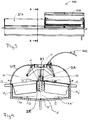
- Fig. 4 is a cross-sectional view along the line indicated by A-A in Fig.3 . It shows a holding arrangement 10 with holding means comprising outer holding means 13, here simply formed by abutting edges or flanges on which outer edges or rims surrounding the upper edge of a canteen are intended to rest.
- Inner holding means 14 also forming edges, are formed by outer edges of the dividing plate 24, thus here separate from the actual holding arrangement, and e.g. supported by a separate holding arrangement provided such as to hold the cooling arrangement and optionally a covering arrangement as can be seen e.g. in Fig. 4 .
- the inner holding means 14 are arranged above the outer holding means, e.g. edges 13, and when mounted the upper back edge of a canteen will form an angle ⁇ of about, here between 7 and 8° with a horizontal plane/line.
- the inner 13 and outer 14 holding means are so arranged with respect to another that a canteen held by them will be arranged such that its inclination angle is ⁇ .
- the holding means may take a number of different forms and operate in different manners as long as this condition is met; the angle ⁇ may also take other values, e.g. between 5.5° and 9.5°,, or preferably between 6.5° and 8.5°, or somewhat smaller and larger values as well.
- the planes 17A, 17A' forming the bottom planes of the holding arrangement preferably also are inclined in opposite directions towards one another, forming an angle +/- ⁇ respectively with a fictive horizontal plane connecting their outer edges.
- the cooling arrangement 20 is arranged in a centralized manner with respect to the vertex V formed at the intersection of these planes with about 70% or two thirds of the cooling arrangement forming a lower portion 20B is disposed between the inner, one another facing back walls of the canteens 1A, 1A', whereas an upper portion 20A, e.g. about 30% or one third of the cooling arrangement (above the dividing plate 24) protrudes above the upper edges of the canteen back walls.
- cooling medium conduits extending longitudinally as explained with reference to Fig. 3 , the cooling medium flows from the upper inlet towards the bottom outlet (not shown in this figure).
- the dividing plate 24 passes longitudinally throughout the cooling arrangement 20, preventing on the upper side cooled air from passing or flowing vertically down to the cold well below the canteens, but urging it to flow across, above, the upper of the canteens.
- the covering arrangement 30 (30A, 30B) is here only schematically illustrated, and is operated by, here, two gas springs for each covering element such as to keep the cover closed and open respectively. The functioning will not be further described since the covering arrangement may take many different forms, the main thing being that a covering arrangement is arranged leaving a space above the canteens allowing a circulation of the air in the arrangement due to the cooled air flowing outwards, downwards due to the inclination of the canteens over the food since cool air has a lower density.
- the holding arrangement may be adapted for taking up one row of canteens, it may be square shaped to take up four rows of canteens arranged with a cooling arrangement in the center of pair wise oppositely arranged canteen back walls, or it may even comprise a circular or oval holding arrangement with surrounding canteens with correspondingly adapted shapes of the canteens or the canteen back walls.
Landscapes
- Physics & Mathematics (AREA)
- Thermal Sciences (AREA)
- Devices That Are Associated With Refrigeration Equipment (AREA)
Description
- The present invention relates to a food bar arrangement according to the first part of claim 1.
- In recent times it has become more and more popular to offer fresh food, salads, fruit vegetables, chicken, but also cooked and prepared food, or so called healthy food, from what often is called a salad bar, where the customer can pick and compose a meal from a number of different products kept in canteens or pans. However, since the food products may remain for some time in the canteens, which may be accessed by quite a large number of persons, the requirements as to an appropriate and hygienic storage capability are high. The products have to be kept under conditions, and at a temperature, preventing bacterial growth, keeping the products fresh, appetizing and not ruined in any way due to the storing.
- To be able to upheld an accurate temperature, e.g. above 0° (to avoid that the products be frozen), but below 8°C, several different arrangements have been proposed.
- Most known arrangements use cooling elements below the canteens but it is difficult to obtain an even temperature distribution in the food stored in the canteens.
-
US 2 201 696 discloses a refrigerated display showcase with an insulating housing and cooling means on the front and rear sides of the housing. The opening to the housing is so located that the housing provides a cold air trap with walls and a bottom. The walls have such a height that by gravity a sufficient depth of cold air can be retained within the housing irrespective of any opening closure. Also here it is difficult to obtain an even temperature distribution in packages held in the housing. - Therefore some arrangements use fan blowers for blowing cold air onto the products e.g. from above, or from below or sideways onto the canteens.
- This is however disadvantageous for several reasons. First, it is not good from a hygienic point of view, bearing in mind that several individuals serve themselves from the canteen which means that air contaminated with bacteria etc. may be blown onto the food. Also other particles, dust may be blown onto the food. Second, due to the air flow, the food products may be dried out, and ruined, at least from an aesthetical point of view and it will not look fresh, which may reduce the willingness from buying and consuming the products. Some articles may even loose taste and undergo unwanted changes.
- These factors contribute in shortening the time period the products can be kept in the canteens, and may have to be disposed of, even if they actually could have been stored for a longer time if stored under appropriate conditions.
- Third, it is a waste of energy to have fan blowers active all the time. Moreover, the difficulties in maintaining an appropriate temperature throughout the entire contents in a canteen, may lead to production of microorganisms, which even may give rise to health hazards.
- It is therefore an object of the present invention to provide a refrigerated food bar arrangement as initially referred to through which one or more of the above mentioned problems can be solved.
- It is also a particular object of the invention to provide an arrangement through which high requirements as to hygiene can be met, and which is capable of conferring a stable temperature distribution throughout the food product kept in a canteen or a pan (all canteens in the bar arrangement).
- Still further it is a particular object to provide an arrangement which is easy to fabricate, which offers a stable, equal temperature throughout the bar, which is easy to regulate and which is easy to operate and also is easy to handle from maintenance and cleaning points of view.
- Another particular object is to provide an arrangement which is flexible and provides an excellent access to the products for the customers. An object is to provide a high standard refrigerated food bar arrangement, particularly of the type intended for self-service, but also for other purposes, e.g. in canteens in schools or restaurants or imbiss stands when staff are serving the customers.
- It is also a particularly an object to provide an arrangement which can be operated without, and does not necessitate the use of any fan blowers.
- Therefore an arrangement is provided which has the characterizing features of claim 1.
- Advantageous embodiments are given by the appended sub claims.
- The invention will in the following be further described in a non-limiting manner, and with reference to the accompanying drawings, in which:
- Fig. 1
- shows a food bar arrangement according to the invention in a perspective view,
- Fig. 2
- is a schematic, longitudinal cross-sectional view through the upper part of the arrangement in
Fig. 1 , - Fig. 3
- is a schematic longitudinal view of an arrangement according to the invention,
- Fig. 4
- is cross-sectional view as seen in the direction of the arrows A-A in
Fig. 3 . -
Fig.1 shows afood bar arrangement 100, e.g. a salad bar, according to a first embodiment of the invention. It comprises a canteen or pan holding arrangement 10 adapted to receive and hold a plurality of canteens or pans 1A1,...,1A9' in which fresh food products will be placed. It further comprises a refrigeratingarrangement 20 adapted to cool the canteens, and the food products provided therein for keeping the food products at a desired temperature, e.g. above 0° but below 8° C, or within a more specified temperature interval. - The holding arrangement 10 comprises a cupboard or a
bench arrangement 15 comprising a cold well adapted to receive the canteens or pans in such a manner that openings of the canteens or pans make the food accessible for a user from a first and a secondouter side section arrangement 100 also comprises acover arrangement 30 adapted to cover the upper, open sections of the canteens or pans so that they will be covered and protected in time periods when not access is required for serving a user, or for refilling the canteens or similar. The covering arrangement in some embodiments also serve the purpose of assisting in the desired even temperature distribution. In some embodiments, though, the covering arrangement may be dispensed with. - The
refrigerating arrangement 20 comprises one or more cooling elements. - The
cooling arrangement 20 comprising cooling elements is arranged with respect to, or in, the holding arrangement 10 such that, when the canteens are taken up therein, each canteen back wall distant from an opposite canteen front wall located adjacent an inner side of the holding arrangement 10 at the outer end sections of the holding arrangement 10 where customer access is provided, will be located close to, facing it, preferably throughout the entire area forming the back wall. - The holding arrangement 10 comprises holding means adapted to hold the canteens or pans in an inclined position such that the outer, upper ends or side edges, of the canteens are arranged at a lower level than opposing inner, upper ends or side edges. Bottom sections of the holding arrangement are disposed such that a distance is left between the bottom surface of the holding arrangement forming a cold well and the bottom portions of the canteens, the distance d (see
Fig. 4 ) being larger below thecooling arrangement 20 than at the outer end portions. - The cooling element or cooling elements are thus arranged to be located adjacent the outer sides of the back walls of the canteens in a mounted position in the holding arrangement 10.
- A first portion 20A of the
cooling arrangement 20 protrudes so as to be arranged above the upper edges of the back walls of the canteens when they are placed in the holding arrangement 10. - A second section 20B of the
cooling arrangement 20 extends downwards towards, but ending at a certain distance from, the bottom of the well or trough of the holding arrangement 10 such that it will be located adjacent substantially the entire back wall of each canteen. - Through the positioning of the canteens in an inclined manner, outwardly downwards away from the
cooling arrangement 20, and the first portion 20A of the cooling arrangement extending upwardly above the inner upper side edges of the back walls, and thecooling arrangement 20 being divided into a (communicating) upper and lower portion, separated by means of a dividing plate 24 (seeFig. 4 ), the cooled air surrounding the upper inner part will flow downwards, outwards above the canteens containing the food, due to the dividing plate hence not being allowed to pass, flow, vertically to the cold well, but is prevented to do so by the dividingplate 24. - Through the second lower portion of the cooling arrangement 10 covering the entire back walls of the canteens and a larger space being formed adjacent, below, the cooling arrangement 10, air with a lower temperature will be distributed and flow towards the outer end sections, under the canteens, so that the canteens or pans, and food provided therein, will be efficiently and evenly cooled from below as well as from above.
- In
Fig 1 thearrangement 100 comprises a holding arrangement 10 which is adapted to receive two parallel rows of canteens 1A1-1A9,1A1'-1A9', thecooling arrangement 20 protruding in a central portion of the bar arrangement above the inner, upper back edges of mounted canteens, and the canteens in each row being held so as to form an inclination angle α of between 5° and 10°, preferably between 6° and 9°, most preferably around 7.5° with a horizontal plane, seeFig. 4 . - The bottom sections of the holding arrangement 10 are preferably also inclined such that an angle β of about 165°-175° is formed at the intersection of the two bottom planes, the vertex being located below the lower end of the
cooling arrangement 20. - In an advantageous embodiment about 30% of the cooling arrangement (the cooling elements), or an upper portion thereof providing about 30% of the cooling effect, is located above the upper edges of the back walls of the canteens when arranged in the holding arrangement, whereas about 70% is located below the upper edges, forming a lower portion, in the shown embodiment between opposite back walls of canteens in the two rows.
-
Fig 2 is a section through an arrangement as shown inFig 1 which illustrates a refrigerating arrangement 20' comprising aninlet 22 at an upper end of the cooling arrangement which is the coolest part, and which is adapted to be connected to a throttle valve (not shown), the cooling arrangement comprising conduits through which a cooling fluid is circulating back and forth throughout the length of the holding arrangement in a number of turns until, at the lower part of thecooling arrangement 20 where it is connected to anoutlet 23, which is adapted to be connected to a compressor (not shown). - In
Fig. 2 also an upper and alower portion 26, 26' of an evaporator are shown, i.e. an evaporator is divided into a lower and an upper evaporation portion. A dividingplate 24 forms an interface between the portions of the cooling arrangement being located above the upper edges of canteens mounted in the holding arrangement and the lower portion respectively as discussed more thoroughly with reference toFigs. 1 ,4 . Preferably outer edges of the dividingplate 24 form inner holding means 14 for holding inner, upper edges of the canteens, which preferably rest on the dividingplate 24. -
Fig 3 also is a longitudinal section through an arrangement as inFig. 1 , wherein the section shown to the left in the Figure illustrates the arrangement when the covering arrangement 30 (30A) is closed, and the section to the right in the Figure schematically illustrates the arrangement when thecovering arrangement 30, or an element thereof 30B, is closed. It should be clear that the covering arrangement may take different forms and may be split up into different sections; one for each a canteen, or one section for two or more canteens in a row etc. -
Fig. 4 is a cross-sectional view along the line indicated by A-A inFig.3 . It shows a holding arrangement 10 with holding means comprising outer holding means 13, here simply formed by abutting edges or flanges on which outer edges or rims surrounding the upper edge of a canteen are intended to rest. - Inner holding means 14, also forming edges, are formed by outer edges of the dividing
plate 24, thus here separate from the actual holding arrangement, and e.g. supported by a separate holding arrangement provided such as to hold the cooling arrangement and optionally a covering arrangement as can be seen e.g. inFig. 4 . The inner holding means 14 are arranged above the outer holding means, e.g. edges 13, and when mounted the upper back edge of a canteen will form an angle α of about, here between 7 and 8° with a horizontal plane/line. - In other words, the inner 13 and outer 14 holding means are so arranged with respect to another that a canteen held by them will be arranged such that its inclination angle is α. The holding means may take a number of different forms and operate in different manners as long as this condition is met; the angle α may also take other values, e.g. between 5.5° and 9.5°,, or preferably between 6.5° and 8.5°, or somewhat smaller and larger values as well.
- The
planes - The
cooling arrangement 20 is arranged in a centralized manner with respect to the vertex V formed at the intersection of these planes with about 70% or two thirds of the cooling arrangement forming a lower portion 20B is disposed between the inner, one another facing back walls of the canteens 1A, 1A', whereas an upper portion 20A, e.g. about 30% or one third of the cooling arrangement (above the dividing plate 24) protrudes above the upper edges of the canteen back walls. - Through cooling medium conduits extending longitudinally as explained with reference to
Fig. 3 , the cooling medium flows from the upper inlet towards the bottom outlet (not shown in this figure). - The dividing
plate 24 passes longitudinally throughout thecooling arrangement 20, preventing on the upper side cooled air from passing or flowing vertically down to the cold well below the canteens, but urging it to flow across, above, the upper of the canteens.
The covering arrangement 30 (30A, 30B) is here only schematically illustrated, and is operated by, here, two gas springs for each covering element such as to keep the cover closed and open respectively. The functioning will not be further described since the covering arrangement may take many different forms, the main thing being that a covering arrangement is arranged leaving a space above the canteens allowing a circulation of the air in the arrangement due to the cooled air flowing outwards, downwards due to the inclination of the canteens over the food since cool air has a lower density. - It should be clear that the invention is not limited to the specifically illustrated embodiments, but that it can be varied in a number of ways within the scope of the appended claims. Particularly it is of course not limited to any particular number of canteens, sizes and shapes of canteens or holding means or cover arrangements.
- Also the holding arrangement may be adapted for taking up one row of canteens, it may be square shaped to take up four rows of canteens arranged with a cooling arrangement in the center of pair wise oppositely arranged canteen back walls, or it may even comprise a circular or oval holding arrangement with surrounding canteens with correspondingly adapted shapes of the canteens or the canteen back walls.
Claims (14)
- A food bar arrangement (100), e.g. a salad bar, comprising a canteen or pan holding arrangement (10) adapted to hold a plurality of canteens or pans for holding fresh food products, a refrigerating arrangement (20') for cooling the arrangement, i.e. food products held in the canteens or pans, and keeping the food products at a desired temperature, wherein the holding arrangement (10) comprises a cupboard or a bench arrangement (15) comprising a cold well, and is adapted to receive the canteens or pans in such a manner that openings of the canteens or pans make the food accessible for a user at least from a first outer side section (15A,15B) of the food bar arrangement allowing the user to choose and pick from the canteens or pans, wherein the refrigerating arrangement (20') comprises a cooling arrangement (20) with one or more cooling elements, that the holding arrangement (10) comprises a bottom with a bottom section or bottom sections, the holding arrangement (10) and the cooling arrangement (20) being so arranged with respect to one another that a distance (d) is provided between the bottom of the holding arrangement forming a cold well and the cooling arrangement (10),
that holding or supporting means (13,14) are provided which are adapted to hold the canteens or pans in an inclined position such that upper edges of the canteens, which when placed in the food bar arrangement will be located adjacent the first outer side section (15A,15B), will be located at a lower level than opposing inner, upper edges,
characterized in
that the cooling arrangement (20) is centrally arranged and in that the holding means are arranged on either sides thereof to allow holding canteens on at least two opposite sides of the cooling arrangement (20), in respective outwardly inclined positions, so that the cooling arrangement (20) peripherally or at least on two sides such may be surrounded by canteens,
that the cooling arrangement is so arranged with respect to the holding arrangement (10) that it will be located close to a location where canteen back walls will be located when held by the holding arrangement (10), said location being distant from the first outer side sections (15A,15B),
that a first portion (20A) of the cooling arrangement extends upwardly from a second lower section (20B) of the cooling arrangement (20) and is arranged above the location where the upper, inner edges of the canteens will be located when placed in the holding arrangement (10), and in that the second lower section (20B) of the cooling arrangement extends downwards towards, but ending at said distance (d) from the bottom of the well or trough of the holding arrangement (10), such that when canteens or pans are mounted in the food bar arrangement, substantially their entire back walls will be located adjacent said lower section (20B) of the cooling arrangement. - A food bar arrangement according to claim 1,
characterized in
the cooling arrangement (20) is separated into the upper and the lower portion (20A,20B) by means of a longitudinal dividing plate (24) . - A food bar arrangement according to claim 2,
characterized in
that the dividing plate (24) is adapted to provide or comprise said inner holding means (14). - A food bar arrangement according to claim 3,
characterized in
that the holding or supporting means comprises inner holding means (14,14) formed by the longitudinal outer edges of the dividing plate (24) hence forming supporting edges on which outwardly directed flanges or similar cooperating means of the canteens may rest. - A food bar arrangement according to any one of claims 1-4,
characterized in
that the holding arrangement (10) is so disposed and that the holding or supporting means comprises outer holding means (13,13) so disposed that two parallel rows of canteens may be taken up, longitudinally along either side of the cooling arrangement (20), the outer holding or supporting means (13,13) being located at a lower level vertically seen than the inner holding or supporting means (14,14). - A food bar arrangement according to any one of claims 1-5,
characterized in
that the bottom sections are oppositely inclined such that an angle between the bottom sections in a plane perpendicular thereto is less than 180°, the vertex (V) or intersection of the plane sections being located below the bottom of the longitudinal lower portion (20B) of the cooling arrangement, a cold well being formed which is arranged to surround front, lateral and bottom walls of canteens or pans placed in the holding arrangement. - A food bar arrangement according to any one of the preceding claims,
characterized in
that the cooling arrangement (20) comprising one or more cooling elements is so disposed that about one third, or about 30%, of the cooling arrangement, corresponding to the upper portion (20A) is located above the dividing plate (24) preferably also defining a vertical position where uppermost, back edges are allowed to be located when located in the bar arrangement, whereas approximately two thirds, or about 70%, corresponding to the lower portion (20B) of the cooling arrangement is disposed below said dividing plate (24). - A food bar arrangement according to any one of the preceding claims,
characterized in
that it further comprises a covering arrangement (30), comprising one or more cover elements (30A,30B), arranged to automatically return to a closed position, e.g. by means of sensor controlled action, or by means of a manual interaction, e.g. assisted by means of a gas spring or similar, optionally also oppositely operating second gas springs or similar being provided to keep the cover temporarily in an open position when opened, so that unless the canteens are serviced, filled with food or servicing a user, a closed system is formed allowing cooled air to flow around the food in the canteens, without requiring any assisted air flow by means of any fan blower. - A food bar arrangement at least according to claim 3,
characterized in
the cooling arrangement (20) is supported by means of upper holding means and extends freely downwards towards the cold well. - A food bar arrangement according to claim 8 and 9,
characterized in
that the cooling arrangement (20) and the covering arrangement (30) are commonly supported and comprise or form the upper holding arrangement. - A food bar arrangement according to any one of the preceding claims,
characterized in
the refrigerating arrangement (20') comprises a cooling arrangement (20) comprising a number of cooling elements allowing a cooling medium to flow in longitudinal conduits adjacent and above the back walls of canteens located in the holding arrangement, wherein the refrigerating arrangement (20') at an upper portion comprises an inlet (22) e.g. for connection to a throttle valve, and at a lower end comprises an outlet (23) e.g. adapted to be connected to a compressor, such that an upper region will be the coolest region. - A food bar arrangement according to any one of the preceding claims,
characterized in
that the canteens in each row are held so as to form an inclination angle α of between 5° and 10°, preferably between 6° and 9°, most preferably around 7.5° with a horizontal plane. - A food bar arrangement according to any one of the preceding claims,
characterized in
that the holding or supporting means comprise inner and/or outer holding or supporting means (13,14) comprising abutting edges provided on the holding arrangement (10). - A food bar arrangement according to claim 1, or any one of claims 4-8,
characterized in
that the holding or supporting means (13,14) and the holding arrangement (10) are adapted to receive canteens on three or more sides, or that the holding arrangement (10) and inner holding or supporting means (14) are disposed allowing canteens to be arranged surrounding the cooling arrangement (20) on two or more sides, or in a continuous manner, e.g. in a circular, oval or rectangular or similar manner.
Applications Claiming Priority (2)
| Application Number | Priority Date | Filing Date | Title |
|---|---|---|---|
| SE1350368A SE538121C2 (en) | 2013-03-22 | 2013-03-22 | A chilled food device |
| PCT/SE2014/000028 WO2014148968A1 (en) | 2013-03-22 | 2014-03-17 | A refrigerated food bar arrangement |
Publications (3)
| Publication Number | Publication Date |
|---|---|
| EP2975974A1 EP2975974A1 (en) | 2016-01-27 |
| EP2975974A4 EP2975974A4 (en) | 2016-12-21 |
| EP2975974B1 true EP2975974B1 (en) | 2018-01-17 |
Family
ID=51583774
Family Applications (1)
| Application Number | Title | Priority Date | Filing Date |
|---|---|---|---|
| EP14768786.7A Active EP2975974B1 (en) | 2013-03-22 | 2014-03-17 | A refrigerated food bar arrangement |
Country Status (3)
| Country | Link |
|---|---|
| EP (1) | EP2975974B1 (en) |
| SE (1) | SE538121C2 (en) |
| WO (1) | WO2014148968A1 (en) |
Families Citing this family (2)
| Publication number | Priority date | Publication date | Assignee | Title |
|---|---|---|---|---|
| SE538676C2 (en) | 2014-05-29 | 2016-10-18 | Picadeli Ab | A refrigerated food bar arrangement and a cooling system forcooling of a food bar |
| SE538647C2 (en) | 2014-05-29 | 2016-10-11 | Picadeli Ab | A lid assembly for a refrigerated food bar assembly and a food bar assembly with such a lid assembly |
Family Cites Families (5)
| Publication number | Priority date | Publication date | Assignee | Title |
|---|---|---|---|---|
| US2201696A (en) * | 1938-11-30 | 1940-05-21 | Bastian Blessing Co | Display showcase |
| US5117649A (en) * | 1991-02-28 | 1992-06-02 | Glenco-Star, Inc. | Horizontal refrigerator |
| US5282367A (en) * | 1992-04-24 | 1994-02-01 | The Delfield Company | Refrigerated food preparation table and method |
| US6547346B2 (en) * | 2000-10-02 | 2003-04-15 | Tyler Refrigeration | Dipping cabinet with improved service door |
| DE202009012288U1 (en) * | 2009-09-09 | 2009-11-19 | Carrier Corp., Farmington | Refrigerator with special arrangement of the fan motor |
-
2013
- 2013-03-22 SE SE1350368A patent/SE538121C2/en unknown
-
2014
- 2014-03-17 WO PCT/SE2014/000028 patent/WO2014148968A1/en not_active Ceased
- 2014-03-17 EP EP14768786.7A patent/EP2975974B1/en active Active
Non-Patent Citations (1)
| Title |
|---|
| None * |
Also Published As
| Publication number | Publication date |
|---|---|
| SE1350368A1 (en) | 2014-09-23 |
| WO2014148968A1 (en) | 2014-09-25 |
| EP2975974A1 (en) | 2016-01-27 |
| SE538121C2 (en) | 2016-03-08 |
| EP2975974A4 (en) | 2016-12-21 |
Similar Documents
| Publication | Publication Date | Title |
|---|---|---|
| US5549373A (en) | Merchandising display with modular shelves | |
| US20090013707A1 (en) | Air blanketed food preparation table | |
| US5860289A (en) | Open floral display case | |
| US5477702A (en) | Refrigerated display cabinet | |
| US10271667B2 (en) | Covering arrangement for a refrigerated food bar arrangement and a food bar arrangement with such a covering arrangement | |
| US20110005409A1 (en) | Heated air curtain container with multiple temperature zones | |
| US10499752B2 (en) | Refrigerated food bar arrangement and a cooling system for such a food bar | |
| US20150230625A1 (en) | Facility for refreshing items displayed for sale with a mist of water droplets | |
| US20060248918A1 (en) | Cooler with container pockets and cold plate | |
| US20080289359A1 (en) | Food serving tray with cooling chamber | |
| WO2014148968A1 (en) | A refrigerated food bar arrangement | |
| US20160304263A1 (en) | Cooling Storage Container for Perishable Items | |
| US576141A (en) | Island | |
| EP3367030B1 (en) | Ice-cream display cabinet and ice-cream drawers | |
| NO319653B3 (en) | Cover for a merchandise storage unit for displaying goods as well as a commodity storage unit with such a cover | |
| EP3037022B1 (en) | Refrigerated display cabinet | |
| ES2314511T3 (en) | REFRIGERATED EXPENDING MACHINE. | |
| EP2095044A2 (en) | Method and device for cooling products | |
| US10709266B1 (en) | Refrigerator display case | |
| US2183868A (en) | Water distributor for ice boxes | |
| JP3131818U (en) | Showcase integrated refrigerator | |
| EP2699127B1 (en) | Island refrigerated display case | |
| EP1486148A1 (en) | Refrigerated display cabinets | |
| US2199195A (en) | Multiple compartment tray | |
| CN110207444B (en) | Refrigerator fresh-keeping room based on cross arrangement |
Legal Events
| Date | Code | Title | Description |
|---|---|---|---|
| PUAI | Public reference made under article 153(3) epc to a published international application that has entered the european phase |
Free format text: ORIGINAL CODE: 0009012 |
|
| 17P | Request for examination filed |
Effective date: 20151016 |
|
| AK | Designated contracting states |
Kind code of ref document: A1 Designated state(s): AL AT BE BG CH CY CZ DE DK EE ES FI FR GB GR HR HU IE IS IT LI LT LU LV MC MK MT NL NO PL PT RO RS SE SI SK SM TR |
|
| AX | Request for extension of the european patent |
Extension state: BA ME |
|
| DAX | Request for extension of the european patent (deleted) | ||
| A4 | Supplementary search report drawn up and despatched |
Effective date: 20161118 |
|
| RIC1 | Information provided on ipc code assigned before grant |
Ipc: A47F 3/04 20060101ALI20161114BHEP Ipc: A47F 10/06 20060101AFI20161114BHEP |
|
| GRAP | Despatch of communication of intention to grant a patent |
Free format text: ORIGINAL CODE: EPIDOSNIGR1 |
|
| INTG | Intention to grant announced |
Effective date: 20170831 |
|
| GRAS | Grant fee paid |
Free format text: ORIGINAL CODE: EPIDOSNIGR3 |
|
| GRAA | (expected) grant |
Free format text: ORIGINAL CODE: 0009210 |
|
| AK | Designated contracting states |
Kind code of ref document: B1 Designated state(s): AL AT BE BG CH CY CZ DE DK EE ES FI FR GB GR HR HU IE IS IT LI LT LU LV MC MK MT NL NO PL PT RO RS SE SI SK SM TR |
|
| REG | Reference to a national code |
Ref country code: GB Ref legal event code: FG4D |
|
| REG | Reference to a national code |
Ref country code: CH Ref legal event code: EP |
|
| REG | Reference to a national code |
Ref country code: IE Ref legal event code: FG4D |
|
| REG | Reference to a national code |
Ref country code: AT Ref legal event code: REF Ref document number: 963844 Country of ref document: AT Kind code of ref document: T Effective date: 20180215 |
|
| REG | Reference to a national code |
Ref country code: DE Ref legal event code: R096 Ref document number: 602014020105 Country of ref document: DE |
|
| REG | Reference to a national code |
Ref country code: FR Ref legal event code: PLFP Year of fee payment: 5 |
|
| REG | Reference to a national code |
Ref country code: NL Ref legal event code: MP Effective date: 20180117 |
|
| REG | Reference to a national code |
Ref country code: LT Ref legal event code: MG4D |
|
| REG | Reference to a national code |
Ref country code: AT Ref legal event code: MK05 Ref document number: 963844 Country of ref document: AT Kind code of ref document: T Effective date: 20180117 |
|
| PG25 | Lapsed in a contracting state [announced via postgrant information from national office to epo] |
Ref country code: NL Free format text: LAPSE BECAUSE OF FAILURE TO SUBMIT A TRANSLATION OF THE DESCRIPTION OR TO PAY THE FEE WITHIN THE PRESCRIBED TIME-LIMIT Effective date: 20180117 |
|
| PG25 | Lapsed in a contracting state [announced via postgrant information from national office to epo] |
Ref country code: FI Free format text: LAPSE BECAUSE OF FAILURE TO SUBMIT A TRANSLATION OF THE DESCRIPTION OR TO PAY THE FEE WITHIN THE PRESCRIBED TIME-LIMIT Effective date: 20180117 Ref country code: NO Free format text: LAPSE BECAUSE OF FAILURE TO SUBMIT A TRANSLATION OF THE DESCRIPTION OR TO PAY THE FEE WITHIN THE PRESCRIBED TIME-LIMIT Effective date: 20180417 Ref country code: CY Free format text: LAPSE BECAUSE OF FAILURE TO SUBMIT A TRANSLATION OF THE DESCRIPTION OR TO PAY THE FEE WITHIN THE PRESCRIBED TIME-LIMIT Effective date: 20180117 Ref country code: ES Free format text: LAPSE BECAUSE OF FAILURE TO SUBMIT A TRANSLATION OF THE DESCRIPTION OR TO PAY THE FEE WITHIN THE PRESCRIBED TIME-LIMIT Effective date: 20180117 Ref country code: HR Free format text: LAPSE BECAUSE OF FAILURE TO SUBMIT A TRANSLATION OF THE DESCRIPTION OR TO PAY THE FEE WITHIN THE PRESCRIBED TIME-LIMIT Effective date: 20180117 Ref country code: LT Free format text: LAPSE BECAUSE OF FAILURE TO SUBMIT A TRANSLATION OF THE DESCRIPTION OR TO PAY THE FEE WITHIN THE PRESCRIBED TIME-LIMIT Effective date: 20180117 |
|
| PG25 | Lapsed in a contracting state [announced via postgrant information from national office to epo] |
Ref country code: BG Free format text: LAPSE BECAUSE OF FAILURE TO SUBMIT A TRANSLATION OF THE DESCRIPTION OR TO PAY THE FEE WITHIN THE PRESCRIBED TIME-LIMIT Effective date: 20180417 Ref country code: AT Free format text: LAPSE BECAUSE OF FAILURE TO SUBMIT A TRANSLATION OF THE DESCRIPTION OR TO PAY THE FEE WITHIN THE PRESCRIBED TIME-LIMIT Effective date: 20180117 Ref country code: RS Free format text: LAPSE BECAUSE OF FAILURE TO SUBMIT A TRANSLATION OF THE DESCRIPTION OR TO PAY THE FEE WITHIN THE PRESCRIBED TIME-LIMIT Effective date: 20180117 Ref country code: IS Free format text: LAPSE BECAUSE OF FAILURE TO SUBMIT A TRANSLATION OF THE DESCRIPTION OR TO PAY THE FEE WITHIN THE PRESCRIBED TIME-LIMIT Effective date: 20180517 Ref country code: SE Free format text: LAPSE BECAUSE OF FAILURE TO SUBMIT A TRANSLATION OF THE DESCRIPTION OR TO PAY THE FEE WITHIN THE PRESCRIBED TIME-LIMIT Effective date: 20180117 Ref country code: LV Free format text: LAPSE BECAUSE OF FAILURE TO SUBMIT A TRANSLATION OF THE DESCRIPTION OR TO PAY THE FEE WITHIN THE PRESCRIBED TIME-LIMIT Effective date: 20180117 Ref country code: PL Free format text: LAPSE BECAUSE OF FAILURE TO SUBMIT A TRANSLATION OF THE DESCRIPTION OR TO PAY THE FEE WITHIN THE PRESCRIBED TIME-LIMIT Effective date: 20180117 Ref country code: GR Free format text: LAPSE BECAUSE OF FAILURE TO SUBMIT A TRANSLATION OF THE DESCRIPTION OR TO PAY THE FEE WITHIN THE PRESCRIBED TIME-LIMIT Effective date: 20180418 |
|
| REG | Reference to a national code |
Ref country code: DE Ref legal event code: R097 Ref document number: 602014020105 Country of ref document: DE |
|
| PG25 | Lapsed in a contracting state [announced via postgrant information from national office to epo] |
Ref country code: EE Free format text: LAPSE BECAUSE OF FAILURE TO SUBMIT A TRANSLATION OF THE DESCRIPTION OR TO PAY THE FEE WITHIN THE PRESCRIBED TIME-LIMIT Effective date: 20180117 Ref country code: RO Free format text: LAPSE BECAUSE OF FAILURE TO SUBMIT A TRANSLATION OF THE DESCRIPTION OR TO PAY THE FEE WITHIN THE PRESCRIBED TIME-LIMIT Effective date: 20180117 Ref country code: IT Free format text: LAPSE BECAUSE OF FAILURE TO SUBMIT A TRANSLATION OF THE DESCRIPTION OR TO PAY THE FEE WITHIN THE PRESCRIBED TIME-LIMIT Effective date: 20180117 Ref country code: AL Free format text: LAPSE BECAUSE OF FAILURE TO SUBMIT A TRANSLATION OF THE DESCRIPTION OR TO PAY THE FEE WITHIN THE PRESCRIBED TIME-LIMIT Effective date: 20180117 |
|
| REG | Reference to a national code |
Ref country code: CH Ref legal event code: PL |
|
| PLBE | No opposition filed within time limit |
Free format text: ORIGINAL CODE: 0009261 |
|
| STAA | Information on the status of an ep patent application or granted ep patent |
Free format text: STATUS: NO OPPOSITION FILED WITHIN TIME LIMIT |
|
| PG25 | Lapsed in a contracting state [announced via postgrant information from national office to epo] |
Ref country code: CZ Free format text: LAPSE BECAUSE OF FAILURE TO SUBMIT A TRANSLATION OF THE DESCRIPTION OR TO PAY THE FEE WITHIN THE PRESCRIBED TIME-LIMIT Effective date: 20180117 Ref country code: MC Free format text: LAPSE BECAUSE OF FAILURE TO SUBMIT A TRANSLATION OF THE DESCRIPTION OR TO PAY THE FEE WITHIN THE PRESCRIBED TIME-LIMIT Effective date: 20180117 Ref country code: SK Free format text: LAPSE BECAUSE OF FAILURE TO SUBMIT A TRANSLATION OF THE DESCRIPTION OR TO PAY THE FEE WITHIN THE PRESCRIBED TIME-LIMIT Effective date: 20180117 Ref country code: DK Free format text: LAPSE BECAUSE OF FAILURE TO SUBMIT A TRANSLATION OF THE DESCRIPTION OR TO PAY THE FEE WITHIN THE PRESCRIBED TIME-LIMIT Effective date: 20180117 Ref country code: SM Free format text: LAPSE BECAUSE OF FAILURE TO SUBMIT A TRANSLATION OF THE DESCRIPTION OR TO PAY THE FEE WITHIN THE PRESCRIBED TIME-LIMIT Effective date: 20180117 |
|
| REG | Reference to a national code |
Ref country code: BE Ref legal event code: MM Effective date: 20180331 |
|
| 26N | No opposition filed |
Effective date: 20181018 |
|
| REG | Reference to a national code |
Ref country code: IE Ref legal event code: MM4A |
|
| PG25 | Lapsed in a contracting state [announced via postgrant information from national office to epo] |
Ref country code: LU Free format text: LAPSE BECAUSE OF NON-PAYMENT OF DUE FEES Effective date: 20180317 |
|
| PG25 | Lapsed in a contracting state [announced via postgrant information from national office to epo] |
Ref country code: IE Free format text: LAPSE BECAUSE OF NON-PAYMENT OF DUE FEES Effective date: 20180317 |
|
| PG25 | Lapsed in a contracting state [announced via postgrant information from national office to epo] |
Ref country code: SI Free format text: LAPSE BECAUSE OF FAILURE TO SUBMIT A TRANSLATION OF THE DESCRIPTION OR TO PAY THE FEE WITHIN THE PRESCRIBED TIME-LIMIT Effective date: 20180117 Ref country code: LI Free format text: LAPSE BECAUSE OF NON-PAYMENT OF DUE FEES Effective date: 20180331 Ref country code: CH Free format text: LAPSE BECAUSE OF NON-PAYMENT OF DUE FEES Effective date: 20180331 Ref country code: BE Free format text: LAPSE BECAUSE OF NON-PAYMENT OF DUE FEES Effective date: 20180331 |
|
| PG25 | Lapsed in a contracting state [announced via postgrant information from national office to epo] |
Ref country code: MT Free format text: LAPSE BECAUSE OF NON-PAYMENT OF DUE FEES Effective date: 20180317 |
|
| PG25 | Lapsed in a contracting state [announced via postgrant information from national office to epo] |
Ref country code: TR Free format text: LAPSE BECAUSE OF FAILURE TO SUBMIT A TRANSLATION OF THE DESCRIPTION OR TO PAY THE FEE WITHIN THE PRESCRIBED TIME-LIMIT Effective date: 20180117 |
|
| PG25 | Lapsed in a contracting state [announced via postgrant information from national office to epo] |
Ref country code: PT Free format text: LAPSE BECAUSE OF FAILURE TO SUBMIT A TRANSLATION OF THE DESCRIPTION OR TO PAY THE FEE WITHIN THE PRESCRIBED TIME-LIMIT Effective date: 20180117 |
|
| PG25 | Lapsed in a contracting state [announced via postgrant information from national office to epo] |
Ref country code: MK Free format text: LAPSE BECAUSE OF NON-PAYMENT OF DUE FEES Effective date: 20180117 Ref country code: HU Free format text: LAPSE BECAUSE OF FAILURE TO SUBMIT A TRANSLATION OF THE DESCRIPTION OR TO PAY THE FEE WITHIN THE PRESCRIBED TIME-LIMIT; INVALID AB INITIO Effective date: 20140317 |
|
| PGFP | Annual fee paid to national office [announced via postgrant information from national office to epo] |
Ref country code: GB Payment date: 20260317 Year of fee payment: 13 |
|
| PGFP | Annual fee paid to national office [announced via postgrant information from national office to epo] |
Ref country code: DE Payment date: 20260318 Year of fee payment: 13 |
|
| PGFP | Annual fee paid to national office [announced via postgrant information from national office to epo] |
Ref country code: FR Payment date: 20260317 Year of fee payment: 13 |