EP2975714B1 - Device housing with fastener nesting provision - Google Patents
Device housing with fastener nesting provision Download PDFInfo
- Publication number
- EP2975714B1 EP2975714B1 EP15174643.5A EP15174643A EP2975714B1 EP 2975714 B1 EP2975714 B1 EP 2975714B1 EP 15174643 A EP15174643 A EP 15174643A EP 2975714 B1 EP2975714 B1 EP 2975714B1
- Authority
- EP
- European Patent Office
- Prior art keywords
- receiving
- item
- yieldable
- receiving post
- removable
- Prior art date
- Legal status (The legal status is an assumption and is not a legal conclusion. Google has not performed a legal analysis and makes no representation as to the accuracy of the status listed.)
- Not-in-force
Links
Images

Classifications
-
- H—ELECTRICITY
- H05—ELECTRIC TECHNIQUES NOT OTHERWISE PROVIDED FOR
- H05K—PRINTED CIRCUITS; CASINGS OR CONSTRUCTIONAL DETAILS OF ELECTRIC APPARATUS; MANUFACTURE OF ASSEMBLAGES OF ELECTRICAL COMPONENTS
- H05K5/00—Casings, cabinets or drawers for electric apparatus
- H05K5/0017—Casings, cabinets or drawers for electric apparatus with operator interface units
-
- H—ELECTRICITY
- H05—ELECTRIC TECHNIQUES NOT OTHERWISE PROVIDED FOR
- H05K—PRINTED CIRCUITS; CASINGS OR CONSTRUCTIONAL DETAILS OF ELECTRIC APPARATUS; MANUFACTURE OF ASSEMBLAGES OF ELECTRICAL COMPONENTS
- H05K5/00—Casings, cabinets or drawers for electric apparatus
- H05K5/02—Details
- H05K5/0204—Mounting supporting structures on the outside of casings
-
- F—MECHANICAL ENGINEERING; LIGHTING; HEATING; WEAPONS; BLASTING
- F16—ENGINEERING ELEMENTS AND UNITS; GENERAL MEASURES FOR PRODUCING AND MAINTAINING EFFECTIVE FUNCTIONING OF MACHINES OR INSTALLATIONS; THERMAL INSULATION IN GENERAL
- F16M—FRAMES, CASINGS OR BEDS OF ENGINES, MACHINES OR APPARATUS, NOT SPECIFIC TO ENGINES, MACHINES OR APPARATUS PROVIDED FOR ELSEWHERE; STANDS; SUPPORTS
- F16M13/00—Other supports for positioning apparatus or articles; Means for steadying hand-held apparatus or articles
- F16M13/02—Other supports for positioning apparatus or articles; Means for steadying hand-held apparatus or articles for supporting on, or attaching to, an object, e.g. tree, gate, window-frame, cycle
-
- H—ELECTRICITY
- H05—ELECTRIC TECHNIQUES NOT OTHERWISE PROVIDED FOR
- H05K—PRINTED CIRCUITS; CASINGS OR CONSTRUCTIONAL DETAILS OF ELECTRIC APPARATUS; MANUFACTURE OF ASSEMBLAGES OF ELECTRICAL COMPONENTS
- H05K5/00—Casings, cabinets or drawers for electric apparatus
- H05K5/02—Details
- H05K5/0217—Mechanical details of casings
Definitions
- the application pertains to wall or surface mountable devices. More particularly, the application pertains to devices of a type usable in regional monitoring systems.
- thermostats such as thermostats, graphical user interfaces, keypads, intercoms, controllers and security devices, including, motion sensors, glassbreak sensors, smoke or carbon monoxide detectors, are usually mounted on a wall or ceiling surface.
- Mounting screws are usually provided in separate package, typically in a sealed plastic bag that ends with trash after installation. The installer will have to open the bag to get screws in hand, and then pick one to install and keep the rest in his/her pocket or somewhere that he/she can reach when up on the ladder.
- Japanese Patent Application 2003120482 discloses a wiring box with inclined grooves with first and second flexible retainers that can hold screws.
- Japanese Patent Application 2000205299 discloses a screw holding construction for a wiring box, with holding portions having mountain shaped cross sections, formed at a bottom wall. A tilting spaces is formed by a through hole.
- Fasteners to be used to install electrical units can be removably inserted in the units' respective housing or mounting plate during the manufacturing process. With this retention feature all, usually 2 or 3, mounting fasteners are pre-located near the mounting holes of a portion of a housing or mounting bracket. No additional packaging is needed for the fasteners.
- the installer does not need to look for, or have to worry about where to keep the fasteners that are to be installed.
- One fastener can be removed to be installed.
- the rest of the fasteners can remain in the unit being installed. They can be removed individually for installation. This will save mounting time, improve user experience and reduce waste.
- FIG. 1 illustrates a configuration 10-1 with three removable fasteners 14-1, -2, -3.
- Fig. 2 illustrates a configuration 10-2 having a different arrangement of three removable fasteners 16-1, -2, -3.
- the above noted fasteners are removably carried by respective pairs, such as 18-1, -2 and 20-1, -2 of yieldable or deformable clamping elements.
- the elements 18-1, -2, 20-1, -2 are integrally molded as part of the respective unit 10-1, 10-2.
- Each of the clamping elements has one end attached to a respective surface, such as 10a, 10b.
- a free second end, as best seen in Fig. 3B deforms as a respective fastener, such as 14-1...-3 or 16-1...-3 is inserted into the respective clamping element.
- the housing portions can also carry additional modules, such as a respective connector module 22a, 22b or 22c for attachment to communications and/or power lines.
- fasteners come within the scope of the appended claims. These include screws, nails, snap fit elements or twist lock elements all without limitation. Those of skill will understand that the exact configuration of the fasteners is not a limitation hereof.
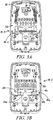
- Figs. 3A and 3B illustrate different aspects hereof in connection with housing portions or mounting plates such as 10-3.
- Pairs of exemplary clamping elements, such as 30a, 30b integrally formed on a respective interior surface, such as 10c, have one end attached to the surface 10c by the molding process, and a second free end which deflects when the respective fastener, such as fasteners 26-1, -2, -3, is inserted between the respective clamping elements.
- optional fastener receiving depressions 34a, 34b can be molded into the surface 10c, best seen in Fig. 3B . Such depressions can improve the grip of the clamping elements 30a, 30b on the respective fastener, such as 26-1, -2 -3.
- fasteners are stored for shipment and for the installer's use on the rear cover portion of the housing, or on a respective mounting plate.
- the installer just picks up the rear cover, takes a fastener off of it, and then drills or otherwise attaches it to a wall or mounting surface. It saves the time that is required to take fasteners out of a plastic bag, and eliminates a need to keep track of them during the mounting process.
- the fasteners are conveniently and securely nested in place at time of manufacture to facilitate the shipping and provisioning of hardware to the installer prior to installation.
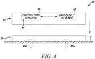
- Fig. 4 illustrates an electrical unit 40 have a base portion, or mounting portion 10-I as described above which can releasibly carry mounting fasteners 46a, b.
- the fasteners 46a, b are illustrated attaching the mounting plate portion 10-I to a surface S.
- the fasteners 46a, b extend through openings 14a, d in the respective unit, such as the unit 10-1., best seen in Fig. 1 .
- Unit 40 can be closed with a cover portion 42 which can be attached to the mounting portion 10-I as would be understood by those of skill in the art.
- the cover portion can carry one or more sensors, 44, control circuits 46 and input output devices 48 as would be understood by those of skill in the art.
- Units, such as the unit 40 can be in wired, via modules 22i, or wireless communication with displaced monitoring and control panels or units without limitation.
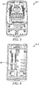
- FIGs. 5, 6 as those of skill will understand that instead of, or in addition to, carrying fasteners, such as 14-1, -2, -3, or 16-1, -2, -3 alternate types of items including wall anchors 60, cable ties 62 or the like, all of which are useful for field mounting or installation, can be releasably carried by the housing portion or mounting plate such as 10-1, -2, -3, or -4.
- fasteners such as 14-1, -2, -3, or 16-1, -2, -3, or 16-1, -2, -3
- alternate types of items including wall anchors 60, cable ties 62 or the like, all of which are useful for field mounting or installation, can be releasably carried by the housing portion or mounting plate such as 10-1, -2, -3, or -4.
Landscapes
- Engineering & Computer Science (AREA)
- Microelectronics & Electronic Packaging (AREA)
- General Engineering & Computer Science (AREA)
- Mechanical Engineering (AREA)
- Casings For Electric Apparatus (AREA)
- Installation Of Indoor Wiring (AREA)
- Clamps And Clips (AREA)
Description
- The application pertains to wall or surface mountable devices. More particularly, the application pertains to devices of a type usable in regional monitoring systems.
- Devices such as thermostats, graphical user interfaces, keypads, intercoms, controllers and security devices, including, motion sensors, glassbreak sensors, smoke or carbon monoxide detectors, are usually mounted on a wall or ceiling surface. Mounting screws are usually provided in separate package, typically in a sealed plastic bag that ends with trash after installation. The installer will have to open the bag to get screws in hand, and then pick one to install and keep the rest in his/her pocket or somewhere that he/she can reach when up on the ladder.
- Japanese Patent Application
2003120482 2000205299 -
-
Fig. 1 is a first embodiment of a part of a housing, or installation element with fasteners; -
Fig. 2 is a second embodiment of a part of a housing, or installation element with fasteners; -
Fig. 3A illustrates an eight conductor embodiment with fasteners; -
Fig. 3B illustrates the embodiment ofFig. 3A without fasteners; -
Fig. 4 illustrates an embodiment, corresponding to any of the embodiments ofFigs. 1-3B closed with a cover; -
Fig. 5 illustrates another embodiment hereof with a cable tie; and -
Fig. 6 illustrates yet another embodiment with a wall anchor. - While disclosed embodiments can take many different forms, specific embodiments hereof are shown in the drawings and will be described herein in detail with the understanding that the present disclosure is to be considered as an exemplification of the principles hereof, as well as the best mode of practicing same, and is not intended to limit the claims hereof to the specific embodiment illustrated.
- Fasteners to be used to install electrical units can be removably inserted in the units' respective housing or mounting plate during the manufacturing process. With this retention feature all, usually 2 or 3, mounting fasteners are pre-located near the mounting holes of a portion of a housing or mounting bracket. No additional packaging is needed for the fasteners.
- The installer does not need to look for, or have to worry about where to keep the fasteners that are to be installed. One fastener can be removed to be installed. The rest of the fasteners can remain in the unit being installed. They can be removed individually for installation. This will save mounting time, improve user experience and reduce waste.
- With respect to
Figs. 1-3B , several different portions of housing or mounting plates 10-1, 10-2 and 10-3 are illustrated. All of the elements 10-1, -2 and -3 removably carry fasteners to attach the respective unit to a wall, ceiling or other mounting surface.Fig. 1 illustrates a configuration 10-1 with three removable fasteners 14-1, -2, -3.Fig. 2 illustrates a configuration 10-2 having a different arrangement of three removable fasteners 16-1, -2, -3. - The above noted fasteners are removably carried by respective pairs, such as 18-1, -2 and 20-1, -2 of yieldable or deformable clamping elements. The elements 18-1, -2, 20-1, -2 are integrally molded as part of the respective unit 10-1, 10-2. Each of the clamping elements has one end attached to a respective surface, such as 10a, 10b. A free second end, as best seen in
Fig. 3B , deforms as a respective fastener, such as 14-1...-3 or 16-1...-3 is inserted into the respective clamping element. - In addition to the molded clamping elements 18-I, or 20-I, the housing portions can also carry additional modules, such as a
respective connector module - It will be understood that a wide variety of fasteners come within the scope of the appended claims. These include screws, nails, snap fit elements or twist lock elements all without limitation. Those of skill will understand that the exact configuration of the fasteners is not a limitation hereof.
-
Figs. 3A and 3B illustrate different aspects hereof in connection with housing portions or mounting plates such as 10-3. Pairs of exemplary clamping elements, such as 30a, 30b integrally formed on a respective interior surface, such as 10c, have one end attached to thesurface 10c by the molding process, and a second free end which deflects when the respective fastener, such as fasteners 26-1, -2, -3, is inserted between the respective clamping elements. - In another embodiment, optional
fastener receiving depressions surface 10c, best seen inFig. 3B . Such depressions can improve the grip of theclamping elements - Thus, as illustrated in the
Figs. 1-3B , fasteners are stored for shipment and for the installer's use on the rear cover portion of the housing, or on a respective mounting plate. When mounting the device, the installer just picks up the rear cover, takes a fastener off of it, and then drills or otherwise attaches it to a wall or mounting surface. It saves the time that is required to take fasteners out of a plastic bag, and eliminates a need to keep track of them during the mounting process. In summary, the fasteners are conveniently and securely nested in place at time of manufacture to facilitate the shipping and provisioning of hardware to the installer prior to installation. -
Fig. 4 illustrates anelectrical unit 40 have a base portion, or mounting portion 10-I as described above which can releasibly carry mounting fasteners 46a, b. The fasteners 46a, b are illustrated attaching the mounting plate portion 10-I to a surface S. The fasteners 46a, b extend through openings 14a, d in the respective unit, such as the unit 10-1., best seen inFig. 1 . -
Unit 40 can be closed with acover portion 42 which can be attached to the mounting portion 10-I as would be understood by those of skill in the art. The cover portion can carry one or more sensors, 44,control circuits 46 andinput output devices 48 as would be understood by those of skill in the art. Units, such as theunit 40 can be in wired, via modules 22i, or wireless communication with displaced monitoring and control panels or units without limitation. - With respect to
Figs. 5, 6 as those of skill will understand that instead of, or in addition to, carrying fasteners, such as 14-1, -2, -3, or 16-1, -2, -3 alternate types of items includingwall anchors 60,cable ties 62 or the like, all of which are useful for field mounting or installation, can be releasably carried by the housing portion or mounting plate such as 10-1, -2, -3, or -4. - The present invention in its various aspects is as set out in the appended claims.
Claims (14)
- An apparatus comprising:a housing (10-1, 10-2, 10-3, 10-4) comprising a removable item storage location within an internal region of the housing (10-1, 10-2, 10-3, 10-4); anda first yieldable receiving post pair (18-1, 20-1) and a second yieldable receiving post pair (18-2, 20-2) both carried in the internal region of the housing (10-1, 10-2, 10-3, 10-4) for releasably receiving a removable item (14-1, 14-2, 14-3, 16-1, 16-2, 16-3, 26-1, 26-2, 26-3, 62, 60) at the removable item storage location,wherein the first yieldable receiving post pair and the second yieldable receiving post pair (18-1, 18-2, 20-1, 20-2) are configured to receive the removable item (14-1, 14-2, 14-3, 16-1, 16-2, 16-3, 26-1, 26-2, 26-3, 62, 60) therebetween,wherein the first yieldable receiving post pair (18-1, 20-1) receives the removable item (14-1, 14-2, 14-3, 16-1, 16-2, 16-3, 26-1, 26-2, 26-3, 62, 60) substantially near a first end of the removable item (14-1, 14-2, 14-3, 16-1, 16-2, 16-3, 26-1, 26-2, 26-3, 62, 60),wherein the second yieldable receiving post pair (18-2, 20-2) receives the removable item (14-1, 14-2, 14-3, 16-1, 16-2, 16-3, 26-1, 26-2, 26-3, 62, 60) substantially near a second end of the removable item (14-1, 14-2, 14-3, 16-1, 16-2, 16-3, 26-1, 26-2, 26-3, 62, 60),wherein the removable item storage location includes a first receiving depression (34a) formed on the housing along a length of the removable item between the first yieldable receiving post pair and the second yieldable receiving post pair, andwherein the removable item storage location includes a second receiving depression (34b) formed on the housing substantially perpendicular to the first receiving depression (34a).
- The apparatus as in claim 1 wherein the housing (10-1, 10-2, 10-3, 10-4) defines a mounting opening (14a, 14b) therethrough, and wherein the removable item (14-1, 14-2, 14-3, 16-1, 16-2, 16-3, 26-1, 26-2, 26-3, 62, 60) is one selected from a class including at least fasteners, wall anchors, and cable ties.
- The apparatus as in claim 2 wherein each of the first yieldable receiving post pair and the second yieldable receiving post pair (18-1, 18-2, 20-1, 20-2) includes a first item receiving post and a second item receiving post (30a, 30b), and wherein the first item receiving post (30a) is positioned adjacent the second item receiving post (30b).
- The apparatus as in claim 3 wherein each of the first item receiving post and the second item receiving post (30a, 30b) has one end attached to an interior surface (10a, 10b, 10c) of the housing (10-1, 10-2, 10-3, 10-4) and an item receiving end extending therefrom.
- The apparatus as in claim 4 wherein the item receiving end includes a deformable clamping portion.
- The apparatus as in claim 3 wherein the first item receiving post and the second item receiving post (30a, 30b) are spaced apart to receive the removable item (14-1, 14-2, 14-3, 16-1, 16-2, 16-3, 26-1, 26-2, 26-3, 62, 60).
- The apparatus as in claim 1 wherein the housing (10-1, 10-2, 10-3, 10-4) defines at least one fastener receiving mounting opening (14a, 14b), and wherein a fastener (14-1, 14-2, 14-3, 16-1, 16-2, 16-3, 26-1, 26-2, 26-3, 62, 60) is inserted through the at least one fastener receiving mounting opening to mount the housing (10-1, 10-2, 10-3, 10-4) on a selected surface.
- The apparatus as in claim 1 wherein each of the first yieldable receiving post pair and the second yieldable receiving post pair (18-1, 18-2, 20-1, 20-2) includes at least a first fastener receiving post and a second fastener receiving post (30a, 30b).
- The apparatus as in claim 1 wherein a cover portion (42) is attachable to the housing (10-1, 10-2, 10-3, 10-4) thereby defining a closed interior region including at least one sensor (44) and associated control circuits (46).
- A device comprising:a three dimensional member (10-1, 10-2, 10-3, 10-4) that defines, in part, an interior region, wherein the three dimensional member (10-1, 10-2, 10-3, 10-4) defines a first item storage receiving depression (34a) and a second item storage receiving depression (34b); anda first yieldable receiving post pair (18-1, 20-1) and a second yieldable receiving post pair (18-2, 20-2) both attached to an internal surface (10a, 10b, 10c) of the three dimensional member (10-1, 10-2, 10-3, 10-4) for releasably receiving a removable item (14-1, 14-2, 14-3, 16-1, 16-2, 16-3, 26-1, 26-2, 26-3, 62, 60),wherein the first yieldable receiving post pair and the second yieldable receiving post pair (18-1, 18-2, 20-1, 20-2) are configured to receive the removable item (14-1, 14-2, 14-3, 16-1, 16-2, 16-3, 26-1, 26-2, 26-3, 62, 60) therebetween,wherein the first yieldable receiving post pair (18-1, 20-1) receives the removable item (14-1, 14-2, 14-3, 16-1, 16-2, 16-3, 26-1, 26-2, 26-3, 62, 60) substantially near a first end of the removable item (14-1, 14-2, 14-3, 16-1, 16-2, 16-3, 26-1, 26-2, 26-3, 62, 60),wherein the second yieldable receiving post pair (18-2, 20-2) receives the removable item (14-1, 14-2, 14-3, 16-1, 16-2, 16-3, 26-1, 26-2, 26-3, 62, 60) substantially near a second end of the removable item (14-1, 14-2, 14-3, 16-1, 16-2, 16-3, 26-1, 26-2, 26-3, 62, 60),wherein the first item storage receiving depression is formed on the three dimensional member along a length of the removable item between the first yieldable receiving post pair and the second yieldable receiving post pair, andwherein the second item storage receiving depression is formed on the three dimensional member substantially perpendicular to the first item storage receiving depression.
- The device as in claim 10 wherein the three dimensional member (10-1, 10-2, 10-3, 10-4) includes a cover portion.
- The device as in claim 10 wherein the three dimensional member (10-1, 10-2, 10-3, 10-4) defines at least one surface mounting opening (14a, 14b).
- The device as in claim 11 further comprising control circuits (46) to implement a predetermined function.
- The device as in claim 13 further comprising at least two fastener storing retainers (18-1, 18-2, 20-1, 20-2).
Applications Claiming Priority (1)
| Application Number | Priority Date | Filing Date | Title |
|---|---|---|---|
| US14/330,300 US9591772B2 (en) | 2014-07-14 | 2014-07-14 | Device housing with fastener nesting provision |
Publications (2)
| Publication Number | Publication Date |
|---|---|
| EP2975714A1 EP2975714A1 (en) | 2016-01-20 |
| EP2975714B1 true EP2975714B1 (en) | 2018-08-15 |
Family
ID=53969078
Family Applications (1)
| Application Number | Title | Priority Date | Filing Date |
|---|---|---|---|
| EP15174643.5A Not-in-force EP2975714B1 (en) | 2014-07-14 | 2015-06-30 | Device housing with fastener nesting provision |
Country Status (5)
| Country | Link |
|---|---|
| US (1) | US9591772B2 (en) |
| EP (1) | EP2975714B1 (en) |
| CN (1) | CN105263280A (en) |
| CA (1) | CA2895374A1 (en) |
| ES (1) | ES2689443T3 (en) |
Families Citing this family (2)
| Publication number | Priority date | Publication date | Assignee | Title |
|---|---|---|---|---|
| CN105592647A (en) * | 2014-10-22 | 2016-05-18 | 富泰华精密电子(郑州)有限公司 | Electronic device |
| FR3050901B1 (en) * | 2016-04-29 | 2018-04-20 | Groupe Brandt | CONTROL AND / OR DISPLAY BOX FOR AN ELECTRICAL APPLIANCE, HOUSEHOLD APPLIANCE INCLUDING SUCH HOUSING AND METHOD FOR ASSEMBLING SUCH HOUSING |
Citations (1)
| Publication number | Priority date | Publication date | Assignee | Title |
|---|---|---|---|---|
| US3822783A (en) * | 1971-03-22 | 1974-07-09 | L Mortensen | Display holder or sales unit |
Family Cites Families (9)
| Publication number | Priority date | Publication date | Assignee | Title |
|---|---|---|---|---|
| JP2001069639A (en) | 1996-04-22 | 2001-03-16 | Mirai Ind Co Ltd | Screw holding structure of wiring box |
| CN1117684C (en) | 2000-08-22 | 2003-08-13 | 宏碁股份有限公司 | screw storage device |
| JP2003299224A (en) | 2003-04-24 | 2003-10-17 | Mirai Ind Co Ltd | Wiring box |
| US7183483B1 (en) | 2005-10-31 | 2007-02-27 | Honeywell International, Inc. | Cover for surface mounted alarm unit |
| US7654784B2 (en) | 2006-01-31 | 2010-02-02 | Honeywell International Inc. | Device housing with integral fastener retainers |
| US7361833B2 (en) * | 2006-03-03 | 2008-04-22 | Thomas & Betts International, Inc. | Pan type ceiling box |
| US7393231B2 (en) * | 2006-04-03 | 2008-07-01 | Tyco Safety Products Canada Ltd. | Methods and apparatus to facilitate component installation |
| US7531744B1 (en) * | 2007-08-31 | 2009-05-12 | Pass & Seymour, Inc. | Ceiling box |
| US9761093B2 (en) | 2011-09-12 | 2017-09-12 | Honeywell International Inc. | Dual strobe expander plate |
-
2014
- 2014-07-14 US US14/330,300 patent/US9591772B2/en active Active
-
2015
- 2015-06-22 CA CA2895374A patent/CA2895374A1/en not_active Abandoned
- 2015-06-30 EP EP15174643.5A patent/EP2975714B1/en not_active Not-in-force
- 2015-06-30 ES ES15174643.5T patent/ES2689443T3/en active Active
- 2015-07-13 CN CN201510407013.5A patent/CN105263280A/en active Pending
Patent Citations (1)
| Publication number | Priority date | Publication date | Assignee | Title |
|---|---|---|---|---|
| US3822783A (en) * | 1971-03-22 | 1974-07-09 | L Mortensen | Display holder or sales unit |
Also Published As
| Publication number | Publication date |
|---|---|
| CN105263280A (en) | 2016-01-20 |
| ES2689443T3 (en) | 2018-11-14 |
| US9591772B2 (en) | 2017-03-07 |
| CA2895374A1 (en) | 2016-01-14 |
| EP2975714A1 (en) | 2016-01-20 |
| US20160014911A1 (en) | 2016-01-14 |
Similar Documents
| Publication | Publication Date | Title |
|---|---|---|
| US9022336B2 (en) | Switch plate adapter | |
| US7778043B2 (en) | Flush mounted assembly for housing an ambient air abnormal condition sensor module | |
| USD797682S1 (en) | Removable face pack for an electronic irrigation controller | |
| US20130063259A1 (en) | Wireless Radio Frequency Switch Controller | |
| WO2004001922A3 (en) | Cable/wire and electronic device storage container | |
| DE50206697D1 (en) | ELECTRONIC PACKAGE COMPARTMENT AND LOGISTICS SYSTEM | |
| US7173186B1 (en) | Dual-sided mounting bracket for electrical junction boxes and method | |
| EP2975714A1 (en) | Device housing with fastener nesting provision | |
| CN109890250B (en) | Fastening system for fixing an electric household appliance in a piece of furniture | |
| ATE305649T1 (en) | MONITORING SYSTEM BASED ON A HANGING DEVICE FOR ELECTRICALLY CONTACT OBJECTS | |
| ITMI20000372U1 (en) | CONTROL UNIT GROUPING OF ELECTRONIC COMPONENTS FOR FREEZER REFRIGERATORS AND SIMILAR APPLIANCES | |
| CN108968407A (en) | A kind of Intelligent office data management cabinet and its application method | |
| US20150349504A1 (en) | Faceplate and hanging device | |
| US8913778B2 (en) | Structure for preventing a fall of a speaker device from a main appliance | |
| AU2003248637A1 (en) | Robust system wiring device wall plate | |
| WO2021079110A1 (en) | Terminal block mounting | |
| GB2400889B (en) | Device for opening a locked door or drawer | |
| RU2005113986A (en) | FRAME | |
| EP3207606B1 (en) | Wall-mounted electrical housing | |
| CA2852337A1 (en) | Faceplate and hanging device | |
| DE202014105750U1 (en) | Holding system for attaching a mobile communication device to a bicycle | |
| US20220235902A1 (en) | Ceiling mounted plastic storage bin holder | |
| US1011164A (en) | Insulator. | |
| JP2007294683A (en) | cabinet | |
| JP6390461B2 (en) | Security communication device |
Legal Events
| Date | Code | Title | Description |
|---|---|---|---|
| PUAI | Public reference made under article 153(3) epc to a published international application that has entered the european phase |
Free format text: ORIGINAL CODE: 0009012 |
|
| 17P | Request for examination filed |
Effective date: 20150630 |
|
| AK | Designated contracting states |
Kind code of ref document: A1 Designated state(s): AL AT BE BG CH CY CZ DE DK EE ES FI FR GB GR HR HU IE IS IT LI LT LU LV MC MK MT NL NO PL PT RO RS SE SI SK SM TR |
|
| AX | Request for extension of the european patent |
Extension state: BA ME |
|
| STAA | Information on the status of an ep patent application or granted ep patent |
Free format text: STATUS: EXAMINATION IS IN PROGRESS |
|
| 17Q | First examination report despatched |
Effective date: 20161102 |
|
| GRAP | Despatch of communication of intention to grant a patent |
Free format text: ORIGINAL CODE: EPIDOSNIGR1 |
|
| STAA | Information on the status of an ep patent application or granted ep patent |
Free format text: STATUS: GRANT OF PATENT IS INTENDED |
|
| INTG | Intention to grant announced |
Effective date: 20180201 |
|
| GRAS | Grant fee paid |
Free format text: ORIGINAL CODE: EPIDOSNIGR3 |
|
| GRAJ | Information related to disapproval of communication of intention to grant by the applicant or resumption of examination proceedings by the epo deleted |
Free format text: ORIGINAL CODE: EPIDOSDIGR1 |
|
| GRAL | Information related to payment of fee for publishing/printing deleted |
Free format text: ORIGINAL CODE: EPIDOSDIGR3 |
|
| GRAP | Despatch of communication of intention to grant a patent |
Free format text: ORIGINAL CODE: EPIDOSNIGR1 |
|
| GRAA | (expected) grant |
Free format text: ORIGINAL CODE: 0009210 |
|
| STAA | Information on the status of an ep patent application or granted ep patent |
Free format text: STATUS: THE PATENT HAS BEEN GRANTED |
|
| INTG | Intention to grant announced |
Effective date: 20180628 |
|
| AK | Designated contracting states |
Kind code of ref document: B1 Designated state(s): AL AT BE BG CH CY CZ DE DK EE ES FI FR GB GR HR HU IE IS IT LI LT LU LV MC MK MT NL NO PL PT RO RS SE SI SK SM TR |
|
| REG | Reference to a national code |
Ref country code: CH Ref legal event code: EP Ref country code: GB Ref legal event code: FG4D Ref country code: AT Ref legal event code: REF Ref document number: 1030874 Country of ref document: AT Kind code of ref document: T Effective date: 20180815 |
|
| REG | Reference to a national code |
Ref country code: IE Ref legal event code: FG4D |
|
| REG | Reference to a national code |
Ref country code: DE Ref legal event code: R096 Ref document number: 602015014681 Country of ref document: DE |
|
| REG | Reference to a national code |
Ref country code: ES Ref legal event code: FG2A Ref document number: 2689443 Country of ref document: ES Kind code of ref document: T3 Effective date: 20181114 |
|
| REG | Reference to a national code |
Ref country code: NL Ref legal event code: MP Effective date: 20180815 |
|
| REG | Reference to a national code |
Ref country code: LT Ref legal event code: MG4D |
|
| REG | Reference to a national code |
Ref country code: AT Ref legal event code: MK05 Ref document number: 1030874 Country of ref document: AT Kind code of ref document: T Effective date: 20180815 |
|
| PG25 | Lapsed in a contracting state [announced via postgrant information from national office to epo] |
Ref country code: LT Free format text: LAPSE BECAUSE OF FAILURE TO SUBMIT A TRANSLATION OF THE DESCRIPTION OR TO PAY THE FEE WITHIN THE PRESCRIBED TIME-LIMIT Effective date: 20180815 Ref country code: IS Free format text: LAPSE BECAUSE OF FAILURE TO SUBMIT A TRANSLATION OF THE DESCRIPTION OR TO PAY THE FEE WITHIN THE PRESCRIBED TIME-LIMIT Effective date: 20181215 Ref country code: RS Free format text: LAPSE BECAUSE OF FAILURE TO SUBMIT A TRANSLATION OF THE DESCRIPTION OR TO PAY THE FEE WITHIN THE PRESCRIBED TIME-LIMIT Effective date: 20180815 Ref country code: AT Free format text: LAPSE BECAUSE OF FAILURE TO SUBMIT A TRANSLATION OF THE DESCRIPTION OR TO PAY THE FEE WITHIN THE PRESCRIBED TIME-LIMIT Effective date: 20180815 Ref country code: GR Free format text: LAPSE BECAUSE OF FAILURE TO SUBMIT A TRANSLATION OF THE DESCRIPTION OR TO PAY THE FEE WITHIN THE PRESCRIBED TIME-LIMIT Effective date: 20181116 Ref country code: FI Free format text: LAPSE BECAUSE OF FAILURE TO SUBMIT A TRANSLATION OF THE DESCRIPTION OR TO PAY THE FEE WITHIN THE PRESCRIBED TIME-LIMIT Effective date: 20180815 Ref country code: SE Free format text: LAPSE BECAUSE OF FAILURE TO SUBMIT A TRANSLATION OF THE DESCRIPTION OR TO PAY THE FEE WITHIN THE PRESCRIBED TIME-LIMIT Effective date: 20180815 Ref country code: NO Free format text: LAPSE BECAUSE OF FAILURE TO SUBMIT A TRANSLATION OF THE DESCRIPTION OR TO PAY THE FEE WITHIN THE PRESCRIBED TIME-LIMIT Effective date: 20181115 Ref country code: NL Free format text: LAPSE BECAUSE OF FAILURE TO SUBMIT A TRANSLATION OF THE DESCRIPTION OR TO PAY THE FEE WITHIN THE PRESCRIBED TIME-LIMIT Effective date: 20180815 Ref country code: BG Free format text: LAPSE BECAUSE OF FAILURE TO SUBMIT A TRANSLATION OF THE DESCRIPTION OR TO PAY THE FEE WITHIN THE PRESCRIBED TIME-LIMIT Effective date: 20181115 |
|
| PG25 | Lapsed in a contracting state [announced via postgrant information from national office to epo] |
Ref country code: HR Free format text: LAPSE BECAUSE OF FAILURE TO SUBMIT A TRANSLATION OF THE DESCRIPTION OR TO PAY THE FEE WITHIN THE PRESCRIBED TIME-LIMIT Effective date: 20180815 Ref country code: LV Free format text: LAPSE BECAUSE OF FAILURE TO SUBMIT A TRANSLATION OF THE DESCRIPTION OR TO PAY THE FEE WITHIN THE PRESCRIBED TIME-LIMIT Effective date: 20180815 Ref country code: AL Free format text: LAPSE BECAUSE OF FAILURE TO SUBMIT A TRANSLATION OF THE DESCRIPTION OR TO PAY THE FEE WITHIN THE PRESCRIBED TIME-LIMIT Effective date: 20180815 |
|
| PG25 | Lapsed in a contracting state [announced via postgrant information from national office to epo] |
Ref country code: RO Free format text: LAPSE BECAUSE OF FAILURE TO SUBMIT A TRANSLATION OF THE DESCRIPTION OR TO PAY THE FEE WITHIN THE PRESCRIBED TIME-LIMIT Effective date: 20180815 Ref country code: CZ Free format text: LAPSE BECAUSE OF FAILURE TO SUBMIT A TRANSLATION OF THE DESCRIPTION OR TO PAY THE FEE WITHIN THE PRESCRIBED TIME-LIMIT Effective date: 20180815 Ref country code: PL Free format text: LAPSE BECAUSE OF FAILURE TO SUBMIT A TRANSLATION OF THE DESCRIPTION OR TO PAY THE FEE WITHIN THE PRESCRIBED TIME-LIMIT Effective date: 20180815 Ref country code: EE Free format text: LAPSE BECAUSE OF FAILURE TO SUBMIT A TRANSLATION OF THE DESCRIPTION OR TO PAY THE FEE WITHIN THE PRESCRIBED TIME-LIMIT Effective date: 20180815 |
|
| REG | Reference to a national code |
Ref country code: DE Ref legal event code: R097 Ref document number: 602015014681 Country of ref document: DE |
|
| PG25 | Lapsed in a contracting state [announced via postgrant information from national office to epo] |
Ref country code: DK Free format text: LAPSE BECAUSE OF FAILURE TO SUBMIT A TRANSLATION OF THE DESCRIPTION OR TO PAY THE FEE WITHIN THE PRESCRIBED TIME-LIMIT Effective date: 20180815 Ref country code: SK Free format text: LAPSE BECAUSE OF FAILURE TO SUBMIT A TRANSLATION OF THE DESCRIPTION OR TO PAY THE FEE WITHIN THE PRESCRIBED TIME-LIMIT Effective date: 20180815 Ref country code: SM Free format text: LAPSE BECAUSE OF FAILURE TO SUBMIT A TRANSLATION OF THE DESCRIPTION OR TO PAY THE FEE WITHIN THE PRESCRIBED TIME-LIMIT Effective date: 20180815 |
|
| PLBE | No opposition filed within time limit |
Free format text: ORIGINAL CODE: 0009261 |
|
| STAA | Information on the status of an ep patent application or granted ep patent |
Free format text: STATUS: NO OPPOSITION FILED WITHIN TIME LIMIT |
|
| 26N | No opposition filed |
Effective date: 20190516 |
|
| PG25 | Lapsed in a contracting state [announced via postgrant information from national office to epo] |
Ref country code: SI Free format text: LAPSE BECAUSE OF FAILURE TO SUBMIT A TRANSLATION OF THE DESCRIPTION OR TO PAY THE FEE WITHIN THE PRESCRIBED TIME-LIMIT Effective date: 20180815 |
|
| PGFP | Annual fee paid to national office [announced via postgrant information from national office to epo] |
Ref country code: CZ Payment date: 20190405 Year of fee payment: 12 |
|
| PG25 | Lapsed in a contracting state [announced via postgrant information from national office to epo] |
Ref country code: MC Free format text: LAPSE BECAUSE OF FAILURE TO SUBMIT A TRANSLATION OF THE DESCRIPTION OR TO PAY THE FEE WITHIN THE PRESCRIBED TIME-LIMIT Effective date: 20180815 |
|
| REG | Reference to a national code |
Ref country code: CH Ref legal event code: PL |
|
| REG | Reference to a national code |
Ref country code: BE Ref legal event code: MM Effective date: 20190630 |
|
| PG25 | Lapsed in a contracting state [announced via postgrant information from national office to epo] |
Ref country code: TR Free format text: LAPSE BECAUSE OF FAILURE TO SUBMIT A TRANSLATION OF THE DESCRIPTION OR TO PAY THE FEE WITHIN THE PRESCRIBED TIME-LIMIT Effective date: 20180815 |
|
| PG25 | Lapsed in a contracting state [announced via postgrant information from national office to epo] |
Ref country code: IE Free format text: LAPSE BECAUSE OF NON-PAYMENT OF DUE FEES Effective date: 20190630 |
|
| PG25 | Lapsed in a contracting state [announced via postgrant information from national office to epo] |
Ref country code: CH Free format text: LAPSE BECAUSE OF NON-PAYMENT OF DUE FEES Effective date: 20190630 Ref country code: LI Free format text: LAPSE BECAUSE OF NON-PAYMENT OF DUE FEES Effective date: 20190630 Ref country code: LU Free format text: LAPSE BECAUSE OF NON-PAYMENT OF DUE FEES Effective date: 20190630 Ref country code: BE Free format text: LAPSE BECAUSE OF NON-PAYMENT OF DUE FEES Effective date: 20190630 |
|
| PG25 | Lapsed in a contracting state [announced via postgrant information from national office to epo] |
Ref country code: PT Free format text: LAPSE BECAUSE OF FAILURE TO SUBMIT A TRANSLATION OF THE DESCRIPTION OR TO PAY THE FEE WITHIN THE PRESCRIBED TIME-LIMIT Effective date: 20181215 |
|
| PGFP | Annual fee paid to national office [announced via postgrant information from national office to epo] |
Ref country code: IT Payment date: 20200618 Year of fee payment: 6 |
|
| REG | Reference to a national code |
Ref country code: GB Ref legal event code: 732E Free format text: REGISTERED BETWEEN 20201126 AND 20201202 |
|
| REG | Reference to a national code |
Ref country code: DE Ref legal event code: R081 Ref document number: 602015014681 Country of ref document: DE Owner name: RESIDEO LLC, WILMINGTON, US Free format text: FORMER OWNER: HONEYWELL INTERNATIONAL INC., MORRIS PLAINS, N.J., US Ref country code: DE Ref legal event code: R081 Ref document number: 602015014681 Country of ref document: DE Owner name: ADEMCO INC., GOLDEN VALLEY, US Free format text: FORMER OWNER: HONEYWELL INTERNATIONAL INC., MORRIS PLAINS, N.J., US |
|
| PG25 | Lapsed in a contracting state [announced via postgrant information from national office to epo] |
Ref country code: CY Free format text: LAPSE BECAUSE OF FAILURE TO SUBMIT A TRANSLATION OF THE DESCRIPTION OR TO PAY THE FEE WITHIN THE PRESCRIBED TIME-LIMIT Effective date: 20180815 |
|
| PG25 | Lapsed in a contracting state [announced via postgrant information from national office to epo] |
Ref country code: HU Free format text: LAPSE BECAUSE OF FAILURE TO SUBMIT A TRANSLATION OF THE DESCRIPTION OR TO PAY THE FEE WITHIN THE PRESCRIBED TIME-LIMIT; INVALID AB INITIO Effective date: 20150630 Ref country code: MT Free format text: LAPSE BECAUSE OF FAILURE TO SUBMIT A TRANSLATION OF THE DESCRIPTION OR TO PAY THE FEE WITHIN THE PRESCRIBED TIME-LIMIT Effective date: 20180815 |
|
| REG | Reference to a national code |
Ref country code: ES Ref legal event code: FD2A Effective date: 20211103 |
|
| PG25 | Lapsed in a contracting state [announced via postgrant information from national office to epo] |
Ref country code: ES Free format text: LAPSE BECAUSE OF NON-PAYMENT OF DUE FEES Effective date: 20200701 |
|
| PG25 | Lapsed in a contracting state [announced via postgrant information from national office to epo] |
Ref country code: MK Free format text: LAPSE BECAUSE OF FAILURE TO SUBMIT A TRANSLATION OF THE DESCRIPTION OR TO PAY THE FEE WITHIN THE PRESCRIBED TIME-LIMIT Effective date: 20180815 |
|
| PG25 | Lapsed in a contracting state [announced via postgrant information from national office to epo] |
Ref country code: IT Free format text: LAPSE BECAUSE OF NON-PAYMENT OF DUE FEES Effective date: 20210630 |
|
| P01 | Opt-out of the competence of the unified patent court (upc) registered |
Effective date: 20230601 |
|
| PGFP | Annual fee paid to national office [announced via postgrant information from national office to epo] |
Ref country code: GB Payment date: 20240618 Year of fee payment: 10 |
|
| PGFP | Annual fee paid to national office [announced via postgrant information from national office to epo] |
Ref country code: FR Payment date: 20240625 Year of fee payment: 10 |
|
| PGFP | Annual fee paid to national office [announced via postgrant information from national office to epo] |
Ref country code: DE Payment date: 20240701 Year of fee payment: 10 |
|
| REG | Reference to a national code |
Ref country code: DE Ref legal event code: R081 Ref document number: 602015014681 Country of ref document: DE Owner name: RESIDEO LLC, WILMINGTON, US Free format text: FORMER OWNER: ADEMCO INC., GOLDEN VALLEY, MN, US |
|
| REG | Reference to a national code |
Ref country code: DE Ref legal event code: R119 Ref document number: 602015014681 Country of ref document: DE |
|
| GBPC | Gb: european patent ceased through non-payment of renewal fee |
Effective date: 20250630 |
|
| PG25 | Lapsed in a contracting state [announced via postgrant information from national office to epo] |
Ref country code: GB Free format text: LAPSE BECAUSE OF NON-PAYMENT OF DUE FEES Effective date: 20250630 |
|
| PG25 | Lapsed in a contracting state [announced via postgrant information from national office to epo] |
Ref country code: DE Free format text: LAPSE BECAUSE OF NON-PAYMENT OF DUE FEES Effective date: 20260101 |
|
| PG25 | Lapsed in a contracting state [announced via postgrant information from national office to epo] |
Ref country code: FR Free format text: LAPSE BECAUSE OF NON-PAYMENT OF DUE FEES Effective date: 20250630 |