EP2974802A1 - Ultrasound probe including a backing member, and method of manufacturing the ultrasound backing member - Google Patents
Ultrasound probe including a backing member, and method of manufacturing the ultrasound backing member Download PDFInfo
- Publication number
- EP2974802A1 EP2974802A1 EP15152721.5A EP15152721A EP2974802A1 EP 2974802 A1 EP2974802 A1 EP 2974802A1 EP 15152721 A EP15152721 A EP 15152721A EP 2974802 A1 EP2974802 A1 EP 2974802A1
- Authority
- EP
- European Patent Office
- Prior art keywords
- ultrasound
- foam
- type body
- backing member
- module
- Prior art date
- Legal status (The legal status is an assumption and is not a legal conclusion. Google has not performed a legal analysis and makes no representation as to the accuracy of the status listed.)
- Granted
Links
Images


Classifications
-
- A—HUMAN NECESSITIES
- A61—MEDICAL OR VETERINARY SCIENCE; HYGIENE
- A61B—DIAGNOSIS; SURGERY; IDENTIFICATION
- A61B8/00—Diagnosis using ultrasonic, sonic or infrasonic waves
- A61B8/44—Constructional features of the ultrasonic, sonic or infrasonic diagnostic device
- A61B8/4483—Constructional features of the ultrasonic, sonic or infrasonic diagnostic device characterised by features of the ultrasound transducer
- A61B8/4494—Constructional features of the ultrasonic, sonic or infrasonic diagnostic device characterised by features of the ultrasound transducer characterised by the arrangement of the transducer elements
-
- A—HUMAN NECESSITIES
- A61—MEDICAL OR VETERINARY SCIENCE; HYGIENE
- A61B—DIAGNOSIS; SURGERY; IDENTIFICATION
- A61B8/00—Diagnosis using ultrasonic, sonic or infrasonic waves
- A61B8/44—Constructional features of the ultrasonic, sonic or infrasonic diagnostic device
- A61B8/4444—Constructional features of the ultrasonic, sonic or infrasonic diagnostic device related to the probe
-
- B—PERFORMING OPERATIONS; TRANSPORTING
- B05—SPRAYING OR ATOMISING IN GENERAL; APPLYING FLUENT MATERIALS TO SURFACES, IN GENERAL
- B05D—PROCESSES FOR APPLYING FLUENT MATERIALS TO SURFACES, IN GENERAL
- B05D1/00—Processes for applying liquids or other fluent materials
- B05D1/18—Processes for applying liquids or other fluent materials performed by dipping
-
- B—PERFORMING OPERATIONS; TRANSPORTING
- B06—GENERATING OR TRANSMITTING MECHANICAL VIBRATIONS IN GENERAL
- B06B—METHODS OR APPARATUS FOR GENERATING OR TRANSMITTING MECHANICAL VIBRATIONS OF INFRASONIC, SONIC, OR ULTRASONIC FREQUENCY, e.g. FOR PERFORMING MECHANICAL WORK IN GENERAL
- B06B1/00—Methods or apparatus for generating mechanical vibrations of infrasonic, sonic, or ultrasonic frequency
- B06B1/02—Methods or apparatus for generating mechanical vibrations of infrasonic, sonic, or ultrasonic frequency making use of electrical energy
- B06B1/06—Methods or apparatus for generating mechanical vibrations of infrasonic, sonic, or ultrasonic frequency making use of electrical energy operating with piezoelectric effect or with electrostriction
-
- G—PHYSICS
- G10—MUSICAL INSTRUMENTS; ACOUSTICS
- G10K—SOUND-PRODUCING DEVICES; METHODS OR DEVICES FOR PROTECTING AGAINST, OR FOR DAMPING, NOISE OR OTHER ACOUSTIC WAVES IN GENERAL; ACOUSTICS NOT OTHERWISE PROVIDED FOR
- G10K11/00—Methods or devices for transmitting, conducting or directing sound in general; Methods or devices for protecting against, or for damping, noise or other acoustic waves in general
- G10K11/002—Devices for damping, suppressing, obstructing or conducting sound in acoustic devices
-
- B—PERFORMING OPERATIONS; TRANSPORTING
- B06—GENERATING OR TRANSMITTING MECHANICAL VIBRATIONS IN GENERAL
- B06B—METHODS OR APPARATUS FOR GENERATING OR TRANSMITTING MECHANICAL VIBRATIONS OF INFRASONIC, SONIC, OR ULTRASONIC FREQUENCY, e.g. FOR PERFORMING MECHANICAL WORK IN GENERAL
- B06B1/00—Methods or apparatus for generating mechanical vibrations of infrasonic, sonic, or ultrasonic frequency
- B06B1/02—Methods or apparatus for generating mechanical vibrations of infrasonic, sonic, or ultrasonic frequency making use of electrical energy
- B06B1/06—Methods or apparatus for generating mechanical vibrations of infrasonic, sonic, or ultrasonic frequency making use of electrical energy operating with piezoelectric effect or with electrostriction
- B06B1/0644—Methods or apparatus for generating mechanical vibrations of infrasonic, sonic, or ultrasonic frequency making use of electrical energy operating with piezoelectric effect or with electrostriction using a single piezoelectric element
- B06B1/0662—Methods or apparatus for generating mechanical vibrations of infrasonic, sonic, or ultrasonic frequency making use of electrical energy operating with piezoelectric effect or with electrostriction using a single piezoelectric element with an electrode on the sensitive surface
- B06B1/0681—Methods or apparatus for generating mechanical vibrations of infrasonic, sonic, or ultrasonic frequency making use of electrical energy operating with piezoelectric effect or with electrostriction using a single piezoelectric element with an electrode on the sensitive surface and a damping structure
- B06B1/0685—Methods or apparatus for generating mechanical vibrations of infrasonic, sonic, or ultrasonic frequency making use of electrical energy operating with piezoelectric effect or with electrostriction using a single piezoelectric element with an electrode on the sensitive surface and a damping structure on the back only of piezoelectric elements
Definitions
- One or more embodiments of the present invention relate to an ultrasound backing member, an ultrasound probe including the ultrasound backing member, and a method of manufacturing the ultrasound backing member.
- Ultrasound diagnosis apparatuses display images in real time, are small and inexpensive, and are safe due to minimal exposure to radiation, compared to other image diagnosis apparatuses, such as, X-ray apparatuses, computerized tomography (CT) scanners, magnetic resonance imaging (MRI) apparatuses, and nuclear medical diagnosis apparatuses. Therefore, ultrasound diagnosis apparatuses are widely used for diagnoses of the heart, the abdomen, the unitary system, and obstetrics and gynecology.
- CT computerized tomography
- MRI magnetic resonance imaging
- Ultrasound diagnosis apparatuses include an ultrasonic probe that transmits an ultrasound signal to an object and receives an echo signal reflected from the object to obtain an image of the object.
- the ultrasonic probe may generate heat while operating.
- a transducer that converts ultrasound waves into an electrical signal or vice versa may generate a lot of heat.
- heat needs to be efficiently discharged.
- One or more embodiments of the present invention include an ultrasound backing member having improved heat conduction, and an ultrasound probe including the ultrasound backing member.
- One or more embodiments of the present invention include a method of manufacturing an ultrasound backing member having improved heat conduction.
- an ultrasound probe includes an ultrasound module comprising a transducer that converts ultrasound waves into an electrical signal or vice versa; and a backing member obtained by filling a porous foam-type body with a backing material that absorbs the ultrasound waves generated by the ultrasound module.
- the foam-type body may include a plurality of pores and a plurality of bridges which are connected to one another and located between the plurality of pores.
- the foam-type body may include a heat-conductive material.
- the foam-type body may include a metal.
- the metal may include at least one selected from copper, aluminum, silver, nickel, iron, gold, and tungsten.
- a pore included in the foam-type body may be connected to at least one of neighboring pores.
- a diameter of at least one of a plurality of pores included in the foam-type body may be about 1 mm to about 10 mm.
- a porosity of the foam-type body may be 50% or more.
- the backing material may include epoxy resin.
- Heat generated in the ultrasound module may be discharged to the outside via the backing member.
- the transducer may include a piezoelectric element that converts the ultrasound waves into the electrical signal or vice versa, by vibrating.
- the backing member may be grounded.
- the backing member may support the ultrasound module.
- the backing member may be disposed on a rear surface of the ultrasound module.
- an ultrasound backing member includes a porous foam-type body; and a backing material that fills the foam-type body and absorbs ultrasound waves.
- the foam-type body may include a heat-conductive material.
- the foam-type body may include a metal.
- a porosity of the foam-type body may be 50% or more.
- a method of manufacturing an ultrasound backing member includes preparing a fluid comprising a backing material that absorbs ultrasound waves; inserting a porous foam-type body into the fluid such that the foam-type body is filled with the backing material; and hardening the foam-type body filled with the backing material.
- the backing material may fill the foam-type body by vibration.
- object used herein may be a human, an animal, or a body part of a human or animal.
- the object may be an organ (e.g., the liver, the heart, the womb, the brain, a breast, or the abdomen), a blood vessel, or a combination thereof.
- user may be, but is not limited thereto, a medical expert, such as a medical doctor, a nurse, a health care technician, or a medical imaging expert, or may be an engineer who repairs medical apparatuses.
- FIG. 1 is a block diagram of an ultrasound diagnosis apparatus 100 according to an embodiment of the present invention.
- the ultrasound diagnosis apparatus 100 includes an ultrasound module 110 that transmits or receives ultrasonic waves, a processor 120 that processes a signal received from the ultrasound probe 110 to generate an image, a display module 130 that displays the image, a user interface 140 that receives an input of a user command, a memory 150 that stores various pieces of information, and a controller 160 that controls overall operations of the ultrasound diagnosis apparatus 100.
- the ultrasound module 110 transmits ultrasound waves to an object and receives an echo signal corresponding to ultrasound waves reflected from the object, as will be described later in detail.
- the processor 120 generates an ultrasound image by processing ultrasound data generated by the ultrasound module 110.
- the ultrasonic image may be at least one of a brightness (B) mode image representing a magnitude of an ultrasonic echo signal by brightness, a Doppler mode image representing an image of a moving object in the form of a spectrum by using the Doppler effect, a motion (M) mode image representing a time-dependent motion of an object at a predetermined position, an elasticity mode image representing a difference between a reaction of an object when compression is applied to the object and a reaction of the object when compression is not applied to the object by an image, and a color (C) mode image representing a speed of a moving object by color by using the Doppler effect.
- B brightness
- Doppler mode image representing an image of a moving object in the form of a spectrum by using the Doppler effect
- M motion
- elasticity mode image representing a difference between a reaction of an object when compression is applied to the object and a reaction of the object when compression is not applied to the
- the ultrasound image may be generated using a currently-usable ultrasound image generating method, and thus, a detailed description thereof will be omitted herein. Accordingly, in the present embodiment, the ultrasound image may be any of images obtained in dimensional modes, such as a one-dimensional (1D) mode, a two-dimensional (2D) mode, a three-dimensional (3D) mode, and a four-dimensional (4D) mode.
- dimensional modes such as a one-dimensional (1D) mode, a two-dimensional (2D) mode, a three-dimensional (3D) mode, and a four-dimensional (4D) mode.
- the display module 130 displays information processed by the ultrasound diagnosis apparatus 100.
- the display module 130 may display the ultrasound image generated by the processor 120, and may also display a graphical user interface (GUI) or the like for requesting a user input.
- GUI graphical user interface
- the display module 130 may be at least one selected from a liquid crystal display (LCD), a thin film transistor-liquid crystal display (TFT-LCD), an organic light-emitting diode (OLED), a flexible display, a 3D display, and an electrophoretic display.
- the ultrasound diagnosis apparatus 100 may include at least two display modules 130.
- the user interface 140 refers to a unit via which a user inputs data for controlling the ultrasound diagnosis apparatus 100.
- the user interface 140 may include a key pad, a mouse, a touch pad, a trackball, and the like.
- the user interface 140 is not limited thereto, and thus may further include various input units such as a jog wheel and a jog switch.
- a touch pad may detect not only a real touch, but may also detect a proximity touch.
- the real touch means a case in which a pointer actually touches a screen
- the proximity touch means a case in which the pointer approaches the screen but does not actually touch the screen.
- the pointer is a tool used for actually touching or proximately touching a predetermined portion of the touch pad. Examples of the tool include a stylus pen, a part of a body such as a finger, and the like.
- the touch pad may be implemented as a touch screen that forms a multiple-layer structure together with the display module 130.
- the touch screen may be variously embodied as a capacitive type touch screen, a pressure resistive type touch screen, an infrared beam sensing type touch screen, a surface acoustic wave type touch screen, an integral strain gauge type touch screen, a piezoelectric effect type touch screen, or the like. Since a touch screen performs the functions of both the display module 130 and the user interface 140, the touch screen is highly utilized.
- a touch pad may include various sensors provided within or near the touch pad.
- An example of the sensor used to detect a touch on the touch pad is a tactile sensor.
- the tactile sensor detects a contact of a specific object with a sensitivity that is equal to or greater than human perception.
- the tactile sensor may detect various types of information, such as the roughness of a touched surface, the hardness of the touching object, and the temperature of a touched point.
- the proximity sensor detects the existence of an object that approaches a predetermined detection surface or that exists nearby, by using an electromagnetic force or infrared rays without any mechanical contact.
- Examples of the proximity sensor include a transmission-type photoelectric sensor, a direct reflection-type photoelectric sensor, a mirror reflection-type photoelectric sensor, a high frequency oscillation-type proximity sensor, a capacity-type proximity sensor, a magnetic proximity sensor, and an infrared-type proximity sensor.
- the memory 150 stores various pieces of information processed by the ultrasound diagnosis apparatus 100.
- the memory 150 may store medical data related to diagnosis of an object, such as an image, and may also store algorithms or programs which are to be executed in the ultrasound diagnosis apparatus 100.
- the memory 150 may include at least one type of storage medium selected from among a flash memory type, a hard disk type, a multimedia card micro type, a card type memory (for example, a secure digital (SD) or extreme digital (XD) memory), a random access memory (RAM), a static random access memory (SRAM), a read-only memory (ROM), an electrically erasable programmable ROM (EEPROM), a programmable ROM (PROM), magnetic memory, a magnetic disk, and an optical disk.
- the ultrasound diagnosis apparatus 100 may utilize web storage or a cloud server which performs the storage function of the memory 150, but online.
- the controller 160 controls all operations of the ultrasound diagnosis apparatus 100. That is, the controller 160 may control operations performed by the ultrasonic module 110, the processor 120, the display module 130, and the like shown in FIG. 1 . For example, the controller 160 may control the processor 120 to produce an image by using a user command that is input via the user interface 140 or by using a program stored in the memory 150. The controller 160 may also control the display module 130 to display the image produced by the processor 120.
- FIG. 2 is a block diagram of the ultrasonic module 110 illustrated in FIG. 1 .
- the ultrasound module 110 may transmit ultrasound waves to an object 10 and receive an echo signal reflected from the object 10 to generate ultrasound data.
- the ultrasound module 110 may include a transmission module 210, a transducer 220, and a reception module 230.
- the transmission module 210 provides a driving signal to the transducer 220.
- the transmission module 210 may include a pulse generation module 212, a transmission delaying unit 214, and a pulser 216.
- the pulse generation module 212 generates rate pulses for generating transmission ultrasound waves based on a predetermined pulse repetition frequency (PRF).
- the transmission delaying module 214 delays the rate pulses generated by the pulse generation module 212 by delay times for determining transmission directionality.
- Each of the rate pulses which have been delayed correspond to a plurality of unit elements included in the transducer 220, respectively.
- the pulser 216 applies a driving signal or a driving pulse to the transducer 220 based on timing that corresponds to each of the rate pulses which have been delayed.
- the plurality of unit elements may be arranged in a 1D array or a 2D array.
- the transducer 220 transmits ultrasound waves to the object 10 in response to the driving signal applied by the transmission module 210 and receives an echo signal corresponding to ultrasound waves reflected by the object 10.
- the transducer 220 may include a plurality of unit elements that convert electrical signals into acoustic energy or vice versa.
- the plurality of unit elements may be arranged in a 1D array or a 2D array.
- the transducer 220 may be a piezoelectric micromachined ultrasonic transducer (pMUT) that converts ultrasound waves into an electrical signal or vice versa according to a pressure change by vibrating, a capacitive micromachined ultrasonic transducer (cMUT) that converts ultrasound waves into an electrical signal or vice versa due to a change in an electrostatic capacity, a magnetic micromachined ultrasonic transducer (mMUT) that converts ultrasound waves into an electrical signal or vice versa based on a change in a magnetic field, or an optical ultrasonic detector that converts ultrasound waves into an electrical signal or vice versa according to a change in optical characteristics.
- pMUT piezoelectric micromachined ultrasonic transducer
- cMUT capacitive micromachined ultrasonic transducer
- mMUT magnetic micromachined ultrasonic transducer
- optical ultrasonic detector that converts ultrasound waves into an electrical signal or vice versa according to a change in optical characteristics.
- the reception module 230 may generate the ultrasound data by processing a signal received from the transducer 220.
- the reception module 230 may include an amplifier 232, an analogue-to-digital converter (ADC) 234, a reception delaying module 236, and a summing module 238.
- ADC analogue-to-digital converter
- the amplifier 232 amplifies the signal received from the transducer 220, and the ADC 234 performs analogue-to-digital conversion on the amplified signal.
- the reception delaying unit 236 delays a digital signal output by the ADC 234 by a delay time necessary for determining reception directionality.
- the summing module 238 generates the ultrasound data by summing signals processed by the reception delaying module 236. A reflection component in a direction determined by the reception directionality may be emphasized by a summing operation of the summing module 238.
- the ultrasound module 110 may necessarily include the transducer 220, but at least some of the transmission module 210 and the reception module 230 may be included in another apparatus.
- the ultrasound module 110 may not include the summing module 238 of the reception module 230.
- the transmission module 210 and the reception module 230 of the ultrasound module 110 may be formed on a single substrate in the form of at least one chip.
- the single substrate may be formed of silicon (Si), ceramic, or a polymer-based material.
- Each block included in the transmission module 210 and the reception module 230 may be formed as a single chip, at least two blocks may be formed as a single chip, or respective blocks of the transmission module 210 and the reception module 230 corresponding to a unit element of the transducer 220 may form a single chip together with the unit element of the transducer 220.
- a substrate including at least one of the transmission module 210 and the reception module 230 is referred to as a chip module substrate.
- the chip module substrate may denote a substrate including all of the chips included in the ultrasound module 110 or may also denote a substrate including some of the chips included in the ultrasound module 110.
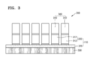
- FIG. 3 is a schematic view of the ultrasound probe 300 according to an embodiment.
- the ultrasound probe 300 includes the ultrasound module 110 which converts an electrical signal into ultrasound waves or vice versa, a backing member 330 which absorbs ultrasound waves that are transmitted in a direction going away from the object, and a matching member 340 which matches an acoustic impedance of the ultrasound waves generated by the ultrasound module 110 with an acoustic impedance of an object.
- the ultrasound module 110 may include the transducer 220 and a chip module substrate 320.
- FIG. 3 illustrates piezoelectric elements 312 as the unit elements of the transducer 220. While vibrating, the piezoelectric elements 312 may convert an electrical signal into an acoustic signal or vice versa.
- the piezoelectric elements 312 may be formed by splitting a piezoelectric material.
- the piezoelectric elements 312 may be manufactured by dicing a piezoelectric material that extends lengthwise.
- a method of manufacturing the piezoelectric elements 312 is not limited to this dicing method, and the piezoelectric elements 312 may be manufactured using various other methods, such as, a method of pressing a piezoelectric material by using a metal mold.
- the piezoelectric material may include at least one selected from ZnO, AlN, PZT(PbZrTiO3), PLZT(PbLaZrTiO3), BT(BaTiO3), PT(PbTiO3), PMN-PT(Pb(Mg1/3Nb2/3)03-PbTiO3), and the like that cause a piezo phenomenon.
- the piezoelectric elements 312 are illustrated as the unit elements of the transducer 220 in FIG. 3 , this is only an example.
- the transducer 220 may include capacitive elements that convert ultrasound waves into an electrical signal or vice versa due to a change in an electrostatic capacity, magnetic elements that convert ultrasound waves into an electrical signal or vice versa due to a change in a magnetic field, or optical elements that convert ultrasound waves into an electrical signal or vice versa according to a change in optical characteristics.
- the backing member 330 may absorb ultrasound waves that are transmitted in a direction going away from the object.
- the backing member 330 may support the chip module substrate 320 at the back surface of the chip module substrate 320 and absorb ultrasound waves that are transmitted toward the back surface of the transducer 220 and are thus not directly used in tests or diagnosis.
- the backing member 330 is separate from the chip module substrate 320, this is only for convenience of explanation, and thus embodiments of the present invention are not limited thereto.
- the chip module substrate 320 may be formed of a backing material 420 (see FIG. 5 ). Thus, the chip module substrate 320 may perform the function of the backing member 330.
- the ultrasound probe 300 may also include the matching member 340 which matches the acoustic impedance of the ultrasound waves generated by the transducer 220 with the acoustic impedance of the object.
- the matching member 340 is disposed on a front surface of the transducer 220 and changes the acoustic impedance of the ultrasound waves generated by the transducer 220 in stages so that the acoustic impedance of the ultrasound waves is approximate to the acoustic impedance of the object.
- the front surface of the transducer 220 may be a surface that is closest to the object from among the surfaces of the transducer 220 when ultrasound waves are applied to the object, and a rear surface thereof may be a surface opposite to the front surface.
- the matching member 340 may be formed of a plurality of matching elements 342 respectively disposed on the piezoelectric elements 312. However, the present embodiment is not limited thereto.
- the matching member 340 may be a single matching element into which the plurality of piezoelectric elements 312 are grouped.
- the matching member 340 may have a single-layered structure or a multi-layered structure.
- the ultrasound probe 300 may further include an acoustic lens (not shown) that focuses ultrasound waves.
- the acoustic lens is disposed on the front surface of the transducer 220 and focuses the ultrasound waves generated by the transducer 220.
- the acoustic lens may be formed of a material such as silicon rubber having an acoustic impedance that is similar to that of the object.
- a central portion of the acoustic lens may be convex or flat.
- the acoustic lens may have various shapes according to designs of manufacturers.
- the ultrasound probe 300 is generating and collecting ultrasound waves
- the piezoelectric elements 312 included in the ultrasound module 110 inevitably vibrate, and heat is generated due to this vibration.
- the amount of generated heat increases in embodiments of the present invention compared with in the conventional art.
- the heat generated in this way fails to be discharged to the outside and is transmitted to the acoustic lens of the ultrasound probe 300, the heat may be transferred directly to the skin of a patient.
- the number of times a patient gets burned may increase.
- the functions of components included in the ultrasound probe 300 may be degraded due to a lot of heat, and accordingly negative effects may be exerted on the safety of a patient and a diagnostic image. Therefore, the ultrasound probe 300 needs to effectively discharge generated heat.
- a backing member included in an ultrasound probe may include a porous foam-type body and a backing material that fills the foam-type body and absorbs ultrasound waves.
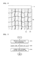
- FIG. 4 illustrates a porous foam-type body 410 according to an embodiment.
- FIG. 5 illustrates a backing member 330 obtained by filling the foam-type body 410 of FIG. 4 with the backing material 420, according to an embodiment.
- the foam-type body 410 may include a plurality of pores 411.
- the foam-type body 410 may include the pores 411 and a plurality of bridges 412 connected to one another and located between the pores 411. The bridges 412 are connected to one another and include a highly heat-conductive material.
- the bridges 412 may include metal.
- the metal may be a highly heat-conductive material, such as copper, aluminum, silver, nickel, iron, gold, or tungsten.
- the bridges 412 of the foam-type body 410 may be connected to one another without disconnections to serve as a passage via which heat generated in an ultrasound probe is discharged to the outside.
- the heat generated in the ultrasound module 110 may be externally discharged via the foam-type body 410, for example, the bridges 412.
- the foam-type body 410 may include the pores 411. At least some of the pores 411 may overlap with each other. In other words, a pore 411 may be connected to at least one of neighboring pores 411. Accordingly, an external material may flow into the foam-type body 410 via the pores 411. Sizes of the pores 411 do not need to be constant, and thus may be irregular.
- a porosity of the foam-type body 410 may be about 50% or more.
- a diameter of each pore 411 may be, but is not limited to, about 1 mm to about 10 mm. The diameter of each of the pores 411 may vary according to methods of manufacturing the foam-type body 410.
- the foam-type body 410 may be manufactured using a bottom-up method, a method using a freeze-drying solution, or a method using a foam base. However, a method of manufacturing the foam-type body 410 is not limited thereto.
- the backing member 330 may not properly absorb ultrasound waves.
- ultrasound waves are not absorbed but are transmitted or reflected by the backing member 330, a distorted ultrasound image may be obtained.
- the pores 411 may be filled with the backing material 420.
- the backing material 420 may include a material having a high attenuation coefficient.
- the backing material 420 may include epoxy resin.
- the backing material 420 may be a combination of a metal powder (for example, tungsten, copper, or aluminum), a ceramic powder (for example, tungsten oxide or alumina), or a carbon allotrope powder (for example, graphite, graphene, carbon nanotubes, or diamond) with epoxy resin, or may include rubber.
- a metal powder for example, tungsten, copper, or aluminum
- a ceramic powder for example, tungsten oxide or alumina
- a carbon allotrope powder for example, graphite, graphene, carbon nanotubes, or diamond
- the foam-type body 410 may include the plurality of pores 411, the pores 411 may be filled with the backing material 420.
- heat generated in the transducer 220 is discharged to the outside via the foam-type body 410, heat transferred to a patient via a lens may be effectively reduced.
- the safety of patients may be secured, and a degradation of the function of an ultrasound diagnosis apparatus due to a lot of heat may be prevented.
- higher power may be applied in consideration of the degree of heat discharge, and thus a clear ultrasound image may be obtained.
- the ultrasound probe 300 may perform a heat discharge function while keeping a conventional shape and size, without including a special heat-discharging apparatus.
- FIG. 6 illustrates a heat transfer path in the backing member 330 of FIG. 5 .
- arrows indicate paths in which heat generated in the ultrasound module 110 is discharged via the backing member 330.
- Most of the heat generated in the ultrasound module 110 is generated in the transducer 220, because the transducer 220 vibrates in response to a voltage and generates an electrical signal by vibrating in response to echo ultrasound waves.
- the backing member 330 may discharge the heat generated in the ultrasound module 110 to the outside.
- the foam-type body 410 of the backing member 330 includes the bridges 412 formed of a highly heat-conductive material, heat may be discharged to the outside via the bridges 412 at high speed.
- a heat sink may be provided on a lower surface of the backing member 330. Since the heat sink may effectively discharge heat, the heat sink may thermally and directly contact the backing member 330 to help a heat discharge. Alternatively, instead that the heat sink directly contacts the backing member 330, the backing member 330 and the heat sink may be connected to each other via a heat pipe. In this case, heat travelling via the backing member 330 is transferred to the heat sink along the heat pipe and is then discharged to the outside.
- a heat discharging fan may also be provided to help the heat sink to discharge heat.
- the heat sink may include a plurality of fins that each have a plate shape and are formed of a metal, such as aluminum, to disperse heat. Heat transferred to the heat sink is dispersed by the plurality of fins, and the heat discharging fan may be disposed near the fins to additionally improve the heat discharge function.
- the backing member 330 when the bridges 412 of the backing member 330 are formed of metal, the backing member 330 may be grounded. Due to the grounding of the backing member 330, interference among electrical signals within the ultrasound probe 300 may be prevented. Moreover, the backing member 330 may serve as a unit that applies a reference voltage, for example, a ground signal, to the transducer 220. In this case, the backing member 330 may contact the transducer 220.
- a reference voltage for example, a ground signal
- FIG. 7 is a flowchart of a method of manufacturing the backing member 330, according to an embodiment.
- the backing material 420 may include a material having a high attenuation coefficient.
- the backing material 420 may include epoxy resin.
- the backing material 420 may be a combination of a metal powder (for example, tungsten, copper, or aluminum), a ceramic powder (for example, tungsten oxide or alumina), or a carbon allotrope powder (for example, graphite, graphene, carbon nanotubes, or diamond) with epoxy resin, or may be rubber.
- the backing material 420 may be mixed with a solvent, for example, water, so as to easily flow.
- the fluid including the backing material 420 may be contained in a chamber.
- the foam-type body 410 is inserted into the fluid.
- the foam-type body 410 may be a porous foam type.
- the foam-type body 410 may include the plurality of pores 411 and the plurality of bridges 412 connected to one another between the pores 411.
- the bridges 412 are connected to one another and may include a highly heat-conductive material.
- the bridges 412 may include metal.
- the metal may be a highly heat-conductive material, such as copper, aluminum, silver, nickel, iron, gold, or tungsten.
- the bridges 412 of the foam-type body 410 may be connected to one another without disconnections to serve as a passage via which heat generated in the ultrasound probe 300 is discharged to the outside.
- the heat generated in the ultrasound module 110 may be externally discharged via the foam-type body 410, for example, the bridges 412.
- the foam-type body 410 may include the pores 411. At least some of the pores 411 may overlap with each other. In other words, a pore 411 may be connected to at least one of neighboring pores 411. Accordingly, an external material may flow into the foam-type body 410 via the pores 411.
- a porosity of the foam-type body 410 may be about 50% or more.
- a diameter of each pore 411 may be, but is not limited to, about 1 mm to about 10 mm.
- the fluid flows into the foam-type body 410 via the pores 411 of the foam-type body 410 to fill the pores 411.
- At least one of the fluid and the foam-type body 410 may be vibrated so that the backing material 420 is filled with the foam-type body 410.
- the chamber that contains the fluid and the foam-type body 410 is vibrated on a vibrator.
- the foam-type body 410 filled with the backing material 420 is hardened to form the backing member 330.
- the backing member 330 manufactured in this way may be cut and joined with the ultrasound module 110 according to use purposes.
Landscapes
- Health & Medical Sciences (AREA)
- Life Sciences & Earth Sciences (AREA)
- Engineering & Computer Science (AREA)
- Physics & Mathematics (AREA)
- Medical Informatics (AREA)
- Animal Behavior & Ethology (AREA)
- Radiology & Medical Imaging (AREA)
- Nuclear Medicine, Radiotherapy & Molecular Imaging (AREA)
- Biomedical Technology (AREA)
- Heart & Thoracic Surgery (AREA)
- Biophysics (AREA)
- Molecular Biology (AREA)
- Surgery (AREA)
- Pathology (AREA)
- General Health & Medical Sciences (AREA)
- Public Health (AREA)
- Veterinary Medicine (AREA)
- Acoustics & Sound (AREA)
- Multimedia (AREA)
- Mechanical Engineering (AREA)
- Gynecology & Obstetrics (AREA)
- Ultra Sonic Daignosis Equipment (AREA)
- Transducers For Ultrasonic Waves (AREA)
Abstract
Description
- This application claims the benefit of Korean Patent Application No.
10-2014-0088449, filed on July 14, 2014 - One or more embodiments of the present invention relate to an ultrasound backing member, an ultrasound probe including the ultrasound backing member, and a method of manufacturing the ultrasound backing member.
- Ultrasound diagnosis apparatuses display images in real time, are small and inexpensive, and are safe due to minimal exposure to radiation, compared to other image diagnosis apparatuses, such as, X-ray apparatuses, computerized tomography (CT) scanners, magnetic resonance imaging (MRI) apparatuses, and nuclear medical diagnosis apparatuses. Therefore, ultrasound diagnosis apparatuses are widely used for diagnoses of the heart, the abdomen, the unitary system, and obstetrics and gynecology.
- Ultrasound diagnosis apparatuses include an ultrasonic probe that transmits an ultrasound signal to an object and receives an echo signal reflected from the object to obtain an image of the object.
- The ultrasonic probe may generate heat while operating. In particular, a transducer that converts ultrasound waves into an electrical signal or vice versa may generate a lot of heat. To maintain the performance of ultrasonic probes, heat needs to be efficiently discharged.
- One or more embodiments of the present invention include an ultrasound backing member having improved heat conduction, and an ultrasound probe including the ultrasound backing member.
- One or more embodiments of the present invention include a method of manufacturing an ultrasound backing member having improved heat conduction.
- Additional aspects will be set forth in part in the description which follows and, in part, will be apparent from the description, or may be learned by practice of the presented embodiments.
- According to one or more embodiments of the present invention, an ultrasound probe includes an ultrasound module comprising a transducer that converts ultrasound waves into an electrical signal or vice versa; and a backing member obtained by filling a porous foam-type body with a backing material that absorbs the ultrasound waves generated by the ultrasound module.
- The foam-type body may include a plurality of pores and a plurality of bridges which are connected to one another and located between the plurality of pores.
- The foam-type body may include a heat-conductive material.
- The foam-type body may include a metal.
- The metal may include at least one selected from copper, aluminum, silver, nickel, iron, gold, and tungsten.
- A pore included in the foam-type body may be connected to at least one of neighboring pores.
- A diameter of at least one of a plurality of pores included in the foam-type body may be about 1 mm to about 10 mm.
- A porosity of the foam-type body may be 50% or more.
- The backing material may include epoxy resin.
- Heat generated in the ultrasound module may be discharged to the outside via the backing member.
- The transducer may include a piezoelectric element that converts the ultrasound waves into the electrical signal or vice versa, by vibrating.
- The backing member may be grounded.
- The backing member may support the ultrasound module.
- The backing member may be disposed on a rear surface of the ultrasound module.
- According to one or more embodiments of the present invention, an ultrasound backing member includes a porous foam-type body; and a backing material that fills the foam-type body and absorbs ultrasound waves.
- The foam-type body may include a heat-conductive material.
- The foam-type body may include a metal.
- A porosity of the foam-type body may be 50% or more.
- According to one or more embodiments of the present invention, a method of manufacturing an ultrasound backing member includes preparing a fluid comprising a backing material that absorbs ultrasound waves; inserting a porous foam-type body into the fluid such that the foam-type body is filled with the backing material; and hardening the foam-type body filled with the backing material.
- The backing material may fill the foam-type body by vibration.
- These and/or other aspects will become apparent and more readily appreciated from the following description of the embodiments, taken in conjunction with the accompanying drawings in which:
-
FIG. 1 is a block diagram of an ultrasound diagnosis apparatus according to an embodiment of the present invention; -
FIG. 2 is a block diagram of an ultrasonic module included in the ultrasound diagnosis apparatus illustrated inFIG. 1 ; -
FIG. 3 is a schematic view of an ultrasound probe according to an embodiment; -
FIG. 4 illustrates a porous foam-type body according to an embodiment; -
FIG. 5 illustrates a backing member obtained by filling the foam-type body ofFIG. 4 with a backing material, according to an embodiment; -
FIG. 6 illustrates a heat transfer path in the backing member ofFIG. 5 ; and -
FIG. 7 is a flowchart of a method of manufacturing a backing member, according to an embodiment. - Embodiments of the invention now will be described more fully hereinafter with reference to the accompanying drawings, in which exemplary embodiments of the invention are shown. In the drawings, like elements are denoted by like reference numerals, and a repeated explanation thereof will not be given.
- The term "object" used herein may be a human, an animal, or a body part of a human or animal. For example, the object may be an organ (e.g., the liver, the heart, the womb, the brain, a breast, or the abdomen), a blood vessel, or a combination thereof. The term "user" may be, but is not limited thereto, a medical expert, such as a medical doctor, a nurse, a health care technician, or a medical imaging expert, or may be an engineer who repairs medical apparatuses.
-
FIG. 1 is a block diagram of anultrasound diagnosis apparatus 100 according to an embodiment of the present invention. Referring toFIG. 1 , theultrasound diagnosis apparatus 100 includes anultrasound module 110 that transmits or receives ultrasonic waves, aprocessor 120 that processes a signal received from theultrasound probe 110 to generate an image, adisplay module 130 that displays the image, auser interface 140 that receives an input of a user command, amemory 150 that stores various pieces of information, and acontroller 160 that controls overall operations of theultrasound diagnosis apparatus 100. - The
ultrasound module 110 transmits ultrasound waves to an object and receives an echo signal corresponding to ultrasound waves reflected from the object, as will be described later in detail. - The
processor 120 generates an ultrasound image by processing ultrasound data generated by theultrasound module 110. The ultrasonic image may be at least one of a brightness (B) mode image representing a magnitude of an ultrasonic echo signal by brightness, a Doppler mode image representing an image of a moving object in the form of a spectrum by using the Doppler effect, a motion (M) mode image representing a time-dependent motion of an object at a predetermined position, an elasticity mode image representing a difference between a reaction of an object when compression is applied to the object and a reaction of the object when compression is not applied to the object by an image, and a color (C) mode image representing a speed of a moving object by color by using the Doppler effect. The ultrasound image may be generated using a currently-usable ultrasound image generating method, and thus, a detailed description thereof will be omitted herein. Accordingly, in the present embodiment, the ultrasound image may be any of images obtained in dimensional modes, such as a one-dimensional (1D) mode, a two-dimensional (2D) mode, a three-dimensional (3D) mode, and a four-dimensional (4D) mode. - The
display module 130 displays information processed by theultrasound diagnosis apparatus 100. For example, thedisplay module 130 may display the ultrasound image generated by theprocessor 120, and may also display a graphical user interface (GUI) or the like for requesting a user input. - The
display module 130 may be at least one selected from a liquid crystal display (LCD), a thin film transistor-liquid crystal display (TFT-LCD), an organic light-emitting diode (OLED), a flexible display, a 3D display, and an electrophoretic display. In some cases, theultrasound diagnosis apparatus 100 may include at least twodisplay modules 130. - The
user interface 140 refers to a unit via which a user inputs data for controlling theultrasound diagnosis apparatus 100. Theuser interface 140 may include a key pad, a mouse, a touch pad, a trackball, and the like. Theuser interface 140 is not limited thereto, and thus may further include various input units such as a jog wheel and a jog switch. - A touch pad may detect not only a real touch, but may also detect a proximity touch. The real touch means a case in which a pointer actually touches a screen, and the proximity touch means a case in which the pointer approaches the screen but does not actually touch the screen. In this specification, the pointer is a tool used for actually touching or proximately touching a predetermined portion of the touch pad. Examples of the tool include a stylus pen, a part of a body such as a finger, and the like.
- The touch pad may be implemented as a touch screen that forms a multiple-layer structure together with the
display module 130. The touch screen may be variously embodied as a capacitive type touch screen, a pressure resistive type touch screen, an infrared beam sensing type touch screen, a surface acoustic wave type touch screen, an integral strain gauge type touch screen, a piezoelectric effect type touch screen, or the like. Since a touch screen performs the functions of both thedisplay module 130 and theuser interface 140, the touch screen is highly utilized. - Although not illustrated in
FIG. 1 , in order to detect a touch, a touch pad may include various sensors provided within or near the touch pad. An example of the sensor used to detect a touch on the touch pad is a tactile sensor. The tactile sensor detects a contact of a specific object with a sensitivity that is equal to or greater than human perception. The tactile sensor may detect various types of information, such as the roughness of a touched surface, the hardness of the touching object, and the temperature of a touched point. - Another example of the sensor used to detect a touch on the touch pad is a proximity sensor. The proximity sensor detects the existence of an object that approaches a predetermined detection surface or that exists nearby, by using an electromagnetic force or infrared rays without any mechanical contact. Examples of the proximity sensor include a transmission-type photoelectric sensor, a direct reflection-type photoelectric sensor, a mirror reflection-type photoelectric sensor, a high frequency oscillation-type proximity sensor, a capacity-type proximity sensor, a magnetic proximity sensor, and an infrared-type proximity sensor.
- The
memory 150 stores various pieces of information processed by theultrasound diagnosis apparatus 100. For example, thememory 150 may store medical data related to diagnosis of an object, such as an image, and may also store algorithms or programs which are to be executed in theultrasound diagnosis apparatus 100. - The
memory 150 may include at least one type of storage medium selected from among a flash memory type, a hard disk type, a multimedia card micro type, a card type memory (for example, a secure digital (SD) or extreme digital (XD) memory), a random access memory (RAM), a static random access memory (SRAM), a read-only memory (ROM), an electrically erasable programmable ROM (EEPROM), a programmable ROM (PROM), magnetic memory, a magnetic disk, and an optical disk. Theultrasound diagnosis apparatus 100 may utilize web storage or a cloud server which performs the storage function of thememory 150, but online. - The
controller 160 controls all operations of theultrasound diagnosis apparatus 100. That is, thecontroller 160 may control operations performed by theultrasonic module 110, theprocessor 120, thedisplay module 130, and the like shown inFIG. 1 . For example, thecontroller 160 may control theprocessor 120 to produce an image by using a user command that is input via theuser interface 140 or by using a program stored in thememory 150. Thecontroller 160 may also control thedisplay module 130 to display the image produced by theprocessor 120. -
FIG. 2 is a block diagram of theultrasonic module 110 illustrated inFIG. 1 . Referring toFIG. 2 , theultrasound module 110 may transmit ultrasound waves to anobject 10 and receive an echo signal reflected from theobject 10 to generate ultrasound data. Theultrasound module 110 may include atransmission module 210, atransducer 220, and areception module 230. - The
transmission module 210 provides a driving signal to thetransducer 220. Thetransmission module 210 may include apulse generation module 212, atransmission delaying unit 214, and apulser 216. - The
pulse generation module 212 generates rate pulses for generating transmission ultrasound waves based on a predetermined pulse repetition frequency (PRF). Thetransmission delaying module 214 delays the rate pulses generated by thepulse generation module 212 by delay times for determining transmission directionality. Each of the rate pulses which have been delayed correspond to a plurality of unit elements included in thetransducer 220, respectively. Thepulser 216 applies a driving signal or a driving pulse to thetransducer 220 based on timing that corresponds to each of the rate pulses which have been delayed. The plurality of unit elements may be arranged in a 1D array or a 2D array. - The
transducer 220 transmits ultrasound waves to theobject 10 in response to the driving signal applied by thetransmission module 210 and receives an echo signal corresponding to ultrasound waves reflected by theobject 10. Thetransducer 220 may include a plurality of unit elements that convert electrical signals into acoustic energy or vice versa. The plurality of unit elements may be arranged in a 1D array or a 2D array. - The
transducer 220 may be a piezoelectric micromachined ultrasonic transducer (pMUT) that converts ultrasound waves into an electrical signal or vice versa according to a pressure change by vibrating, a capacitive micromachined ultrasonic transducer (cMUT) that converts ultrasound waves into an electrical signal or vice versa due to a change in an electrostatic capacity, a magnetic micromachined ultrasonic transducer (mMUT) that converts ultrasound waves into an electrical signal or vice versa based on a change in a magnetic field, or an optical ultrasonic detector that converts ultrasound waves into an electrical signal or vice versa according to a change in optical characteristics. - The
reception module 230 may generate the ultrasound data by processing a signal received from thetransducer 220. Thereception module 230 may include anamplifier 232, an analogue-to-digital converter (ADC) 234, areception delaying module 236, and a summingmodule 238. - The
amplifier 232 amplifies the signal received from thetransducer 220, and theADC 234 performs analogue-to-digital conversion on the amplified signal. Thereception delaying unit 236 delays a digital signal output by theADC 234 by a delay time necessary for determining reception directionality. The summingmodule 238 generates the ultrasound data by summing signals processed by thereception delaying module 236. A reflection component in a direction determined by the reception directionality may be emphasized by a summing operation of the summingmodule 238. - The
ultrasound module 110 may necessarily include thetransducer 220, but at least some of thetransmission module 210 and thereception module 230 may be included in another apparatus. For example, theultrasound module 110 may not include the summingmodule 238 of thereception module 230. - The
transmission module 210 and thereception module 230 of theultrasound module 110 may be formed on a single substrate in the form of at least one chip. Here, the single substrate may be formed of silicon (Si), ceramic, or a polymer-based material. Each block included in thetransmission module 210 and thereception module 230 may be formed as a single chip, at least two blocks may be formed as a single chip, or respective blocks of thetransmission module 210 and thereception module 230 corresponding to a unit element of thetransducer 220 may form a single chip together with the unit element of thetransducer 220. Thus, a substrate including at least one of thetransmission module 210 and thereception module 230 is referred to as a chip module substrate. The chip module substrate may denote a substrate including all of the chips included in theultrasound module 110 or may also denote a substrate including some of the chips included in theultrasound module 110. - A physical structure including the
ultrasound module 110 is referred to as anultrasound probe 300.FIG. 3 is a schematic view of theultrasound probe 300 according to an embodiment. As illustrated inFIG. 3 , theultrasound probe 300 includes theultrasound module 110 which converts an electrical signal into ultrasound waves or vice versa, abacking member 330 which absorbs ultrasound waves that are transmitted in a direction going away from the object, and a matchingmember 340 which matches an acoustic impedance of the ultrasound waves generated by theultrasound module 110 with an acoustic impedance of an object. - The
ultrasound module 110 may include thetransducer 220 and achip module substrate 320.FIG. 3 illustratespiezoelectric elements 312 as the unit elements of thetransducer 220. While vibrating, thepiezoelectric elements 312 may convert an electrical signal into an acoustic signal or vice versa. Thepiezoelectric elements 312 may be formed by splitting a piezoelectric material. For example, thepiezoelectric elements 312 may be manufactured by dicing a piezoelectric material that extends lengthwise. However, a method of manufacturing thepiezoelectric elements 312 is not limited to this dicing method, and thepiezoelectric elements 312 may be manufactured using various other methods, such as, a method of pressing a piezoelectric material by using a metal mold. The piezoelectric material may include at least one selected from ZnO, AlN, PZT(PbZrTiO3), PLZT(PbLaZrTiO3), BT(BaTiO3), PT(PbTiO3), PMN-PT(Pb(Mg1/3Nb2/3)03-PbTiO3), and the like that cause a piezo phenomenon. - Although the
piezoelectric elements 312 are illustrated as the unit elements of thetransducer 220 inFIG. 3 , this is only an example. Thetransducer 220 may include capacitive elements that convert ultrasound waves into an electrical signal or vice versa due to a change in an electrostatic capacity, magnetic elements that convert ultrasound waves into an electrical signal or vice versa due to a change in a magnetic field, or optical elements that convert ultrasound waves into an electrical signal or vice versa according to a change in optical characteristics. - The
backing member 330 may absorb ultrasound waves that are transmitted in a direction going away from the object. Thebacking member 330 may support thechip module substrate 320 at the back surface of thechip module substrate 320 and absorb ultrasound waves that are transmitted toward the back surface of thetransducer 220 and are thus not directly used in tests or diagnosis. Although thebacking member 330 is separate from thechip module substrate 320, this is only for convenience of explanation, and thus embodiments of the present invention are not limited thereto. Thechip module substrate 320 may be formed of a backing material 420 (seeFIG. 5 ). Thus, thechip module substrate 320 may perform the function of thebacking member 330. - The
ultrasound probe 300 may also include the matchingmember 340 which matches the acoustic impedance of the ultrasound waves generated by thetransducer 220 with the acoustic impedance of the object. The matchingmember 340 is disposed on a front surface of thetransducer 220 and changes the acoustic impedance of the ultrasound waves generated by thetransducer 220 in stages so that the acoustic impedance of the ultrasound waves is approximate to the acoustic impedance of the object. The front surface of thetransducer 220 may be a surface that is closest to the object from among the surfaces of thetransducer 220 when ultrasound waves are applied to the object, and a rear surface thereof may be a surface opposite to the front surface. - The matching
member 340 may be formed of a plurality of matchingelements 342 respectively disposed on thepiezoelectric elements 312. However, the present embodiment is not limited thereto. The matchingmember 340 may be a single matching element into which the plurality ofpiezoelectric elements 312 are grouped. The matchingmember 340 may have a single-layered structure or a multi-layered structure. - The
ultrasound probe 300 may further include an acoustic lens (not shown) that focuses ultrasound waves. The acoustic lens is disposed on the front surface of thetransducer 220 and focuses the ultrasound waves generated by thetransducer 220. The acoustic lens may be formed of a material such as silicon rubber having an acoustic impedance that is similar to that of the object. A central portion of the acoustic lens may be convex or flat. The acoustic lens may have various shapes according to designs of manufacturers. - While the
ultrasound probe 300 is generating and collecting ultrasound waves, thepiezoelectric elements 312 included in theultrasound module 110 inevitably vibrate, and heat is generated due to this vibration. In addition, since components included in ultrasound probes are highly integrated with miniaturization of the ultrasound probes, the amount of generated heat increases in embodiments of the present invention compared with in the conventional art. - If the heat generated in this way fails to be discharged to the outside and is transmitted to the acoustic lens of the
ultrasound probe 300, the heat may be transferred directly to the skin of a patient. Thus, the number of times a patient gets burned may increase. The functions of components included in theultrasound probe 300 may be degraded due to a lot of heat, and accordingly negative effects may be exerted on the safety of a patient and a diagnostic image. Therefore, theultrasound probe 300 needs to effectively discharge generated heat. - A backing member included in an ultrasound probe according to an embodiment may include a porous foam-type body and a backing material that fills the foam-type body and absorbs ultrasound waves.
FIG. 4 illustrates a porous foam-type body 410 according to an embodiment.FIG. 5 illustrates abacking member 330 obtained by filling the foam-type body 410 ofFIG. 4 with thebacking material 420, according to an embodiment. As illustrated inFIG. 4 , the foam-type body 410 may include a plurality ofpores 411. In detail, the foam-type body 410 may include thepores 411 and a plurality ofbridges 412 connected to one another and located between thepores 411. Thebridges 412 are connected to one another and include a highly heat-conductive material. For example, thebridges 412 may include metal. The metal may be a highly heat-conductive material, such as copper, aluminum, silver, nickel, iron, gold, or tungsten. Thebridges 412 of the foam-type body 410 may be connected to one another without disconnections to serve as a passage via which heat generated in an ultrasound probe is discharged to the outside. Thus, the heat generated in theultrasound module 110 may be externally discharged via the foam-type body 410, for example, thebridges 412. - The foam-
type body 410 may include thepores 411. At least some of thepores 411 may overlap with each other. In other words, apore 411 may be connected to at least one of neighboring pores 411. Accordingly, an external material may flow into the foam-type body 410 via thepores 411. Sizes of thepores 411 do not need to be constant, and thus may be irregular. A porosity of the foam-type body 410 may be about 50% or more. A diameter of eachpore 411 may be, but is not limited to, about 1 mm to about 10 mm. The diameter of each of thepores 411 may vary according to methods of manufacturing the foam-type body 410. - The foam-
type body 410 may be manufactured using a bottom-up method, a method using a freeze-drying solution, or a method using a foam base. However, a method of manufacturing the foam-type body 410 is not limited thereto. - When the
backing member 330 includes only the foam-type body 410, the backingmember 330 may not properly absorb ultrasound waves. When ultrasound waves are not absorbed but are transmitted or reflected by the backingmember 330, a distorted ultrasound image may be obtained. In thebacking member 330, thepores 411 may be filled with thebacking material 420. Thebacking material 420 may include a material having a high attenuation coefficient. For example, thebacking material 420 may include epoxy resin. Alternatively, thebacking material 420 may be a combination of a metal powder (for example, tungsten, copper, or aluminum), a ceramic powder (for example, tungsten oxide or alumina), or a carbon allotrope powder (for example, graphite, graphene, carbon nanotubes, or diamond) with epoxy resin, or may include rubber. - As described above, since the foam-
type body 410 may include the plurality ofpores 411, thepores 411 may be filled with thebacking material 420. In addition, since heat generated in thetransducer 220 is discharged to the outside via the foam-type body 410, heat transferred to a patient via a lens may be effectively reduced. When a heat discharge is effectively performed, the safety of patients may be secured, and a degradation of the function of an ultrasound diagnosis apparatus due to a lot of heat may be prevented. Moreover, when power is applied to generate ultrasound waves, higher power may be applied in consideration of the degree of heat discharge, and thus a clear ultrasound image may be obtained. - Since the
ultrasound probe 300 includes thebacking member 330, theultrasound probe 300 may perform a heat discharge function while keeping a conventional shape and size, without including a special heat-discharging apparatus. -
FIG. 6 illustrates a heat transfer path in thebacking member 330 ofFIG. 5 . InFIG. 6 , arrows indicate paths in which heat generated in theultrasound module 110 is discharged via thebacking member 330. Most of the heat generated in theultrasound module 110 is generated in thetransducer 220, because thetransducer 220 vibrates in response to a voltage and generates an electrical signal by vibrating in response to echo ultrasound waves. Thebacking member 330 may discharge the heat generated in theultrasound module 110 to the outside. In detail, since the foam-type body 410 of thebacking member 330 includes thebridges 412 formed of a highly heat-conductive material, heat may be discharged to the outside via thebridges 412 at high speed. - Although not shown in
FIG. 3 , a heat sink may be provided on a lower surface of thebacking member 330. Since the heat sink may effectively discharge heat, the heat sink may thermally and directly contact thebacking member 330 to help a heat discharge. Alternatively, instead that the heat sink directly contacts thebacking member 330, the backingmember 330 and the heat sink may be connected to each other via a heat pipe. In this case, heat travelling via thebacking member 330 is transferred to the heat sink along the heat pipe and is then discharged to the outside. - According to an embodiment, a heat discharging fan may also be provided to help the heat sink to discharge heat. The heat sink may include a plurality of fins that each have a plate shape and are formed of a metal, such as aluminum, to disperse heat. Heat transferred to the heat sink is dispersed by the plurality of fins, and the heat discharging fan may be disposed near the fins to additionally improve the heat discharge function.
- According to an embodiment, when the
bridges 412 of thebacking member 330 are formed of metal, the backingmember 330 may be grounded. Due to the grounding of thebacking member 330, interference among electrical signals within theultrasound probe 300 may be prevented. Moreover, the backingmember 330 may serve as a unit that applies a reference voltage, for example, a ground signal, to thetransducer 220. In this case, the backingmember 330 may contact thetransducer 220. -
FIG. 7 is a flowchart of a method of manufacturing thebacking member 330, according to an embodiment. - First, in operation S710, a fluid including the
backing material 420 absorbing ultrasound waves is prepared. Thebacking material 420 may include a material having a high attenuation coefficient. For example, thebacking material 420 may include epoxy resin. Alternatively, thebacking material 420 may be a combination of a metal powder (for example, tungsten, copper, or aluminum), a ceramic powder (for example, tungsten oxide or alumina), or a carbon allotrope powder (for example, graphite, graphene, carbon nanotubes, or diamond) with epoxy resin, or may be rubber. Thebacking material 420 may be mixed with a solvent, for example, water, so as to easily flow. Thus, the fluid including thebacking material 420 may be contained in a chamber. - In operation S720, the foam-
type body 410 is inserted into the fluid. The foam-type body 410 may be a porous foam type. The foam-type body 410 may include the plurality ofpores 411 and the plurality ofbridges 412 connected to one another between thepores 411. Thebridges 412 are connected to one another and may include a highly heat-conductive material. For example, thebridges 412 may include metal. The metal may be a highly heat-conductive material, such as copper, aluminum, silver, nickel, iron, gold, or tungsten. Thebridges 412 of the foam-type body 410 may be connected to one another without disconnections to serve as a passage via which heat generated in theultrasound probe 300 is discharged to the outside. Thus, the heat generated in theultrasound module 110 may be externally discharged via the foam-type body 410, for example, thebridges 412. The foam-type body 410 may include thepores 411. At least some of thepores 411 may overlap with each other. In other words, apore 411 may be connected to at least one of neighboring pores 411. Accordingly, an external material may flow into the foam-type body 410 via thepores 411. A porosity of the foam-type body 410 may be about 50% or more. A diameter of eachpore 411 may be, but is not limited to, about 1 mm to about 10 mm. - When the porous foam-
type body 410 is inserted into the fluid, the fluid flows into the foam-type body 410 via thepores 411 of the foam-type body 410 to fill thepores 411. At least one of the fluid and the foam-type body 410 may be vibrated so that thebacking material 420 is filled with the foam-type body 410. In other words, the chamber that contains the fluid and the foam-type body 410 is vibrated on a vibrator. - In operation S730, the foam-
type body 410 filled with thebacking material 420 is hardened to form thebacking member 330. Thebacking member 330 manufactured in this way may be cut and joined with theultrasound module 110 according to use purposes. - Various embodiments other than the above-described embodiment exist within the claims of the present invention. As the invention allows for various changes and numerous embodiments, exemplary embodiments will be illustrated in the drawings and described in detail in the written description. However, this is not intended to limit the present invention to particular modes of practice, and it is to be appreciated that all changes, equivalents, and substitutes that do not depart from the spirit and technical scope of the present invention are encompassed in the present invention.
Claims (15)
- An ultrasound probe comprising:an ultrasound module comprising a transducer that converts ultrasound waves into an electrical signal or vice versa; anda backing member obtained by filling a porous foam-type body with a backing material that absorbs the ultrasound waves generated by the ultrasound module.
- The ultrasound probe of claim 1, wherein the foam-type body comprises a plurality of pores and a plurality of bridges which are connected to one another and located between the plurality of pores.
- The ultrasound probe of claim 1 or 2, wherein the foam-type body comprises a heat-conductive material.
- The ultrasound probe of any one of claims 1 to 3, wherein the foam-type body comprises a metal.
- The ultrasound probe of claim 4, wherein the metal comprises at least one selected from copper, aluminum, silver, nickel, iron, gold, and tungsten.
- The ultrasound probe of any one of claims 1 to 5, wherein a pore included in the foam-type body is connected to at least one of neighboring pores.
- The ultrasound probe of any one of claims 1 to 6, wherein a diameter of at least one of a plurality of pores included in the foam-type body is about 1 mm to about 10 mm.
- The ultrasound probe of any one of claims 1 to 7, wherein a porosity of the foam-type body is 50% or more.
- The ultrasound probe of any one of claims 1 to 8, wherein the backing material comprises epoxy resin.
- The ultrasound probe of any one of claims 1 to 9, wherein heat generated in the ultrasound module is discharged to the outside via the backing member.
- The ultrasound probe of any one of claim 1 to 10, wherein the transducer comprises a piezoelectric element that converts the ultrasound waves into the electrical signal or vice versa, by vibrating.
- The ultrasound probe of any one of claims 1 to 11, wherein the backing member is grounded.
- The ultrasound probe of any one of claims 1 to 12, wherein the backing member supports the ultrasound module.
- A method of manufacturing an ultrasound backing member, the method comprising:preparing a fluid comprising a backing material that absorbs ultrasound waves;inserting a porous foam-type body into the fluid such that the foam-type body is filled with the backing material; andhardening the foam-type body filled with the backing material.
- The method of claim 14, wherein the backing material fills the foam-type body by vibration.
Applications Claiming Priority (1)
| Application Number | Priority Date | Filing Date | Title |
|---|---|---|---|
| KR1020140088449A KR102271172B1 (en) | 2014-07-14 | 2014-07-14 | Ultrasonic backing elememt, ultrasonic probe including the same and the method of manufacturing thereof |
Publications (2)
| Publication Number | Publication Date |
|---|---|
| EP2974802A1 true EP2974802A1 (en) | 2016-01-20 |
| EP2974802B1 EP2974802B1 (en) | 2020-04-29 |
Family
ID=52394994
Family Applications (1)
| Application Number | Title | Priority Date | Filing Date |
|---|---|---|---|
| EP15152721.5A Active EP2974802B1 (en) | 2014-07-14 | 2015-01-27 | Ultrasound probe including a backing member |
Country Status (4)
| Country | Link |
|---|---|
| US (1) | US20160007961A1 (en) |
| EP (1) | EP2974802B1 (en) |
| KR (1) | KR102271172B1 (en) |
| CN (1) | CN105286913A (en) |
Cited By (2)
| Publication number | Priority date | Publication date | Assignee | Title |
|---|---|---|---|---|
| EP4062168A4 (en) * | 2019-11-22 | 2023-11-15 | Exo Imaging Inc. | ULTRASONIC TRANSDUCER WITH ACOUSTIC ABSORBER STRUCTURE |
| DE102019131412B4 (en) | 2018-11-21 | 2024-04-18 | Siemens Medical Solutions Usa, Inc. | COMPOSITE ACOUSTIC ABSORBER FOR AN ULTRASONIC TRANSDUCER ARRANGEMENT |
Families Citing this family (20)
| Publication number | Priority date | Publication date | Assignee | Title |
|---|---|---|---|---|
| JP6598721B2 (en) * | 2016-04-01 | 2019-10-30 | 富士フイルム株式会社 | Acoustic matching member, acoustic matching member group, and medical imaging apparatus |
| CN105784849A (en) * | 2016-04-15 | 2016-07-20 | 江苏省特种设备安全监督检验研究院 | Novel graphene ultrasonic probe |
| EP3518775B1 (en) * | 2016-10-03 | 2025-06-25 | Koninklijke Philips N.V. | Temperature insensitive backing structure for intraluminal imaging devices |
| WO2018112042A1 (en) * | 2016-12-13 | 2018-06-21 | Butterfly Network, Inc. | Acoustic lens and applications thereof |
| US10275634B2 (en) | 2017-03-16 | 2019-04-30 | Qualcomm Incorporated | Ultrasonic fingerprint sensor with acoustic shielding |
| JP7292305B2 (en) | 2018-01-02 | 2023-06-16 | コーニンクレッカ フィリップス エヌ ヴェ | High Power Microbeamformer Ultrasound Transducer Probe |
| US10966683B2 (en) | 2018-03-22 | 2021-04-06 | Exo Imaging Inc. | Integrated ultrasonic transducers |
| JP7333684B2 (en) * | 2018-04-26 | 2023-08-25 | 三菱鉛筆株式会社 | ultrasonic probe |
| KR102074986B1 (en) * | 2018-06-26 | 2020-02-07 | 지하정보기술 (주) | Sonic Transducer Unit for Nondestructive Inspection with Easy Contact on the surface of structure |
| CN110960258A (en) * | 2018-09-30 | 2020-04-07 | 深圳迈瑞生物医疗电子股份有限公司 | an ultrasonic probe |
| WO2020137966A1 (en) * | 2018-12-26 | 2020-07-02 | 京セラ株式会社 | Ultrasound device |
| JP7151531B2 (en) * | 2019-02-14 | 2022-10-12 | Tdk株式会社 | Piezoelectric composition, piezoelectric element, piezoelectric device, piezoelectric transformer, ultrasonic motor, ultrasonic wave generating element and filter element |
| KR20210136133A (en) | 2019-03-25 | 2021-11-16 | 엑소 이미징, 인크. | handheld ultrasound imaging device |
| KR102757707B1 (en) | 2019-04-11 | 2025-01-21 | 삼성메디슨 주식회사 | Ultrasonic probe and ultrasonic imaging apparatus having the same |
| WO2021050853A1 (en) | 2019-09-12 | 2021-03-18 | Exo Imaging, Inc. | Increased mut coupling efficiency and bandwidth via edge groove, virtual pivots, and free boundaries |
| CN110507354A (en) * | 2019-09-18 | 2019-11-29 | 无锡祥生医疗科技股份有限公司 | Energy saving ultrasonic probe, energy saving ultrasonic device and energy saving ultrasonic probe electricity-fetching method |
| EP4645300A3 (en) | 2020-03-05 | 2026-01-28 | Exo Imaging Inc. | Ultrasonic imaging device with programmable anatomy and flow imaging |
| US20230256223A1 (en) * | 2022-01-27 | 2023-08-17 | Becton, Dickinson And Company | Utilizing Ultrasound Waves for Infection Prevention in Vascular Access Devices |
| KR200497687Y1 (en) * | 2023-10-13 | 2024-01-25 | 주식회사 한소노 | Ultrasound device |
| CN120080475A (en) * | 2025-04-11 | 2025-06-03 | 上海声一电子科技有限公司 | A method for preparing a conductive backing structure, a conductive backing structure and an ultrasonic transducer |
Citations (5)
| Publication number | Priority date | Publication date | Assignee | Title |
|---|---|---|---|---|
| US3376438A (en) * | 1965-06-21 | 1968-04-02 | Magnaflux Corp | Piezoelectric ultrasonic transducer |
| US7046583B2 (en) * | 2001-12-07 | 2006-05-16 | Thales | High-power transmission acoustic antenna |
| US20120238880A1 (en) * | 2011-03-17 | 2012-09-20 | Koninklijke Philips Electronics N.V. | Composite acoustic backing with high thermal conductivity for ultrasound transducer array |
| WO2013140283A2 (en) * | 2012-03-20 | 2013-09-26 | Koninklijke Philips N.V. | Ultrasonic matrix array probe with thermally dissipating cable and backing block heat exchange |
| EP2842642A2 (en) * | 2013-08-28 | 2015-03-04 | Samsung Medison Co., Ltd. | Ultrasonic probe and method of manufacturing the same |
Family Cites Families (8)
| Publication number | Priority date | Publication date | Assignee | Title |
|---|---|---|---|---|
| JPH0869233A (en) * | 1994-08-26 | 1996-03-12 | Xerox Corp | Assembly of xerographic image formation member |
| JP4624659B2 (en) * | 2003-09-30 | 2011-02-02 | パナソニック株式会社 | Ultrasonic probe |
| US20050127793A1 (en) * | 2003-12-15 | 2005-06-16 | Baumgartner Charles E. | Acoustic backing material for small-element ultrasound transducer arrays |
| WO2006033232A1 (en) * | 2004-09-21 | 2006-03-30 | Olympus Corporation | Ultrasonic vibrator, ultrasonic vibrator array, and ultrsonic endoscope device |
| WO2007069609A1 (en) * | 2005-12-14 | 2007-06-21 | Murata Manufacturing Co., Ltd. | Ultrasonic transducer |
| JP2012015680A (en) * | 2010-06-30 | 2012-01-19 | Toshiba Corp | Ultrasonic probe and ultrasonic diagnosis apparatus |
| WO2012023619A1 (en) * | 2010-08-20 | 2012-02-23 | 株式会社日立メディコ | Ultrasound probe and ultrasound diagnostic device using same |
| KR101403905B1 (en) * | 2012-01-19 | 2014-06-11 | 삼성메디슨 주식회사 | Probe for ultrasonic diagnostic apparatus and method of manufacturing the same |
-
2014
- 2014-07-14 KR KR1020140088449A patent/KR102271172B1/en active Active
-
2015
- 2015-01-27 EP EP15152721.5A patent/EP2974802B1/en active Active
- 2015-03-04 US US14/637,514 patent/US20160007961A1/en not_active Abandoned
- 2015-06-02 CN CN201510296016.6A patent/CN105286913A/en active Pending
Patent Citations (5)
| Publication number | Priority date | Publication date | Assignee | Title |
|---|---|---|---|---|
| US3376438A (en) * | 1965-06-21 | 1968-04-02 | Magnaflux Corp | Piezoelectric ultrasonic transducer |
| US7046583B2 (en) * | 2001-12-07 | 2006-05-16 | Thales | High-power transmission acoustic antenna |
| US20120238880A1 (en) * | 2011-03-17 | 2012-09-20 | Koninklijke Philips Electronics N.V. | Composite acoustic backing with high thermal conductivity for ultrasound transducer array |
| WO2013140283A2 (en) * | 2012-03-20 | 2013-09-26 | Koninklijke Philips N.V. | Ultrasonic matrix array probe with thermally dissipating cable and backing block heat exchange |
| EP2842642A2 (en) * | 2013-08-28 | 2015-03-04 | Samsung Medison Co., Ltd. | Ultrasonic probe and method of manufacturing the same |
Cited By (4)
| Publication number | Priority date | Publication date | Assignee | Title |
|---|---|---|---|---|
| DE102019131412B4 (en) | 2018-11-21 | 2024-04-18 | Siemens Medical Solutions Usa, Inc. | COMPOSITE ACOUSTIC ABSORBER FOR AN ULTRASONIC TRANSDUCER ARRANGEMENT |
| US12383230B2 (en) | 2018-11-21 | 2025-08-12 | Siemens Medical Solutions Usa, Inc. | Composite acoustic absorber for ultrasound transducer array |
| EP4062168A4 (en) * | 2019-11-22 | 2023-11-15 | Exo Imaging Inc. | ULTRASONIC TRANSDUCER WITH ACOUSTIC ABSORBER STRUCTURE |
| TWI875867B (en) * | 2019-11-22 | 2025-03-11 | 美商艾克索影像股份有限公司 | Thermally conductive acoustic absorber, ultrasound probe comprising the same and method of forming the same |
Also Published As
| Publication number | Publication date |
|---|---|
| EP2974802B1 (en) | 2020-04-29 |
| US20160007961A1 (en) | 2016-01-14 |
| KR20160008360A (en) | 2016-01-22 |
| KR102271172B1 (en) | 2021-06-30 |
| CN105286913A (en) | 2016-02-03 |
Similar Documents
| Publication | Publication Date | Title |
|---|---|---|
| EP2974802B1 (en) | Ultrasound probe including a backing member | |
| KR101563500B1 (en) | Gel patch for probe and Ultrasonic diagnostic apparatus comprising the same | |
| EP3199251B1 (en) | Ultrasonic transducer and ultrasonic probe including the same | |
| KR101915255B1 (en) | Method of manufacturing the ultrasonic probe and the ultrasonic probe | |
| US20150115773A1 (en) | Ultrasound transducer and method for manufacturing an ultrasound transducer | |
| US20150099960A1 (en) | Ultrasonic probe and medical apparatus including the same | |
| KR20140144466A (en) | Portable Ultrasonic Probe | |
| EP3047917A1 (en) | Matching member and ultrasound probe including the same | |
| US20150196276A1 (en) | Ultrasonic probe and method of manufacturing the same | |
| EP2839887B1 (en) | Acoustic probe and method of manufacturing the same | |
| CN106974674A (en) | Ultrasonic probe and the method for manufacturing the ultrasonic probe | |
| US10251623B2 (en) | Support apparatus of ultrasound probe, handsfree ultrasound probe including the support apparatus, and method of operating the support apparatus | |
| JP2021087493A (en) | Ultrasonic probe and ultrasonic diagnostic device | |
| JP7465988B2 (en) | ULTRASONIC SYSTEM AND METHOD FOR CONTROLLING AN ULTRASONIC SYSTEM - Patent application | |
| JP7187350B2 (en) | Ultrasonic probe and ultrasonic diagnostic equipment | |
| EP2902116A2 (en) | Ultrasonic probe and method of manufacturing the same | |
| KR102249526B1 (en) | Method for manufacturing ultrasonic probe and ultrasonic probe | |
| KR20180068586A (en) | Probe for ultrasonic diagnostic apparatus | |
| TW202034853A (en) | Wearable scanning and therapy assembly |
Legal Events
| Date | Code | Title | Description |
|---|---|---|---|
| PUAI | Public reference made under article 153(3) epc to a published international application that has entered the european phase |
Free format text: ORIGINAL CODE: 0009012 |
|
| AK | Designated contracting states |
Kind code of ref document: A1 Designated state(s): AL AT BE BG CH CY CZ DE DK EE ES FI FR GB GR HR HU IE IS IT LI LT LU LV MC MK MT NL NO PL PT RO RS SE SI SK SM TR |
|
| AX | Request for extension of the european patent |
Extension state: BA ME |
|
| 17P | Request for examination filed |
Effective date: 20160630 |
|
| RBV | Designated contracting states (corrected) |
Designated state(s): AL AT BE BG CH CY CZ DE DK EE ES FI FR GB GR HR HU IE IS IT LI LT LU LV MC MK MT NL NO PL PT RO RS SE SI SK SM TR |
|
| STAA | Information on the status of an ep patent application or granted ep patent |
Free format text: STATUS: EXAMINATION IS IN PROGRESS |
|
| 17Q | First examination report despatched |
Effective date: 20180313 |
|
| GRAP | Despatch of communication of intention to grant a patent |
Free format text: ORIGINAL CODE: EPIDOSNIGR1 |
|
| STAA | Information on the status of an ep patent application or granted ep patent |
Free format text: STATUS: GRANT OF PATENT IS INTENDED |
|
| INTG | Intention to grant announced |
Effective date: 20191218 |
|
| RIN1 | Information on inventor provided before grant (corrected) |
Inventor name: SON, KWANG-JIN Inventor name: NAM, GI-UNG Inventor name: LEE, SUNG-JAE Inventor name: LEE, WON-HEE Inventor name: SONG, KYUNG-HUN Inventor name: KIM, SANG-MIN |
|
| GRAS | Grant fee paid |
Free format text: ORIGINAL CODE: EPIDOSNIGR3 |
|
| GRAA | (expected) grant |
Free format text: ORIGINAL CODE: 0009210 |
|
| STAA | Information on the status of an ep patent application or granted ep patent |
Free format text: STATUS: THE PATENT HAS BEEN GRANTED |
|
| AK | Designated contracting states |
Kind code of ref document: B1 Designated state(s): AL AT BE BG CH CY CZ DE DK EE ES FI FR GB GR HR HU IE IS IT LI LT LU LV MC MK MT NL NO PL PT RO RS SE SI SK SM TR |
|
| REG | Reference to a national code |
Ref country code: GB Ref legal event code: FG4D |
|
| REG | Reference to a national code |
Ref country code: CH Ref legal event code: EP |
|
| REG | Reference to a national code |
Ref country code: DE Ref legal event code: R096 Ref document number: 602015051475 Country of ref document: DE |
|
| REG | Reference to a national code |
Ref country code: AT Ref legal event code: REF Ref document number: 1262520 Country of ref document: AT Kind code of ref document: T Effective date: 20200515 |
|
| REG | Reference to a national code |
Ref country code: IE Ref legal event code: FG4D |
|
| REG | Reference to a national code |
Ref country code: NL Ref legal event code: MP Effective date: 20200429 |
|
| REG | Reference to a national code |
Ref country code: LT Ref legal event code: MG4D |
|
| PG25 | Lapsed in a contracting state [announced via postgrant information from national office to epo] |
Ref country code: FI Free format text: LAPSE BECAUSE OF FAILURE TO SUBMIT A TRANSLATION OF THE DESCRIPTION OR TO PAY THE FEE WITHIN THE PRESCRIBED TIME-LIMIT Effective date: 20200429 Ref country code: GR Free format text: LAPSE BECAUSE OF FAILURE TO SUBMIT A TRANSLATION OF THE DESCRIPTION OR TO PAY THE FEE WITHIN THE PRESCRIBED TIME-LIMIT Effective date: 20200730 Ref country code: SE Free format text: LAPSE BECAUSE OF FAILURE TO SUBMIT A TRANSLATION OF THE DESCRIPTION OR TO PAY THE FEE WITHIN THE PRESCRIBED TIME-LIMIT Effective date: 20200429 Ref country code: LT Free format text: LAPSE BECAUSE OF FAILURE TO SUBMIT A TRANSLATION OF THE DESCRIPTION OR TO PAY THE FEE WITHIN THE PRESCRIBED TIME-LIMIT Effective date: 20200429 Ref country code: PT Free format text: LAPSE BECAUSE OF FAILURE TO SUBMIT A TRANSLATION OF THE DESCRIPTION OR TO PAY THE FEE WITHIN THE PRESCRIBED TIME-LIMIT Effective date: 20200831 Ref country code: NO Free format text: LAPSE BECAUSE OF FAILURE TO SUBMIT A TRANSLATION OF THE DESCRIPTION OR TO PAY THE FEE WITHIN THE PRESCRIBED TIME-LIMIT Effective date: 20200729 Ref country code: IS Free format text: LAPSE BECAUSE OF FAILURE TO SUBMIT A TRANSLATION OF THE DESCRIPTION OR TO PAY THE FEE WITHIN THE PRESCRIBED TIME-LIMIT Effective date: 20200829 |
|
| REG | Reference to a national code |
Ref country code: AT Ref legal event code: MK05 Ref document number: 1262520 Country of ref document: AT Kind code of ref document: T Effective date: 20200429 |
|
| PG25 | Lapsed in a contracting state [announced via postgrant information from national office to epo] |
Ref country code: RS Free format text: LAPSE BECAUSE OF FAILURE TO SUBMIT A TRANSLATION OF THE DESCRIPTION OR TO PAY THE FEE WITHIN THE PRESCRIBED TIME-LIMIT Effective date: 20200429 Ref country code: LV Free format text: LAPSE BECAUSE OF FAILURE TO SUBMIT A TRANSLATION OF THE DESCRIPTION OR TO PAY THE FEE WITHIN THE PRESCRIBED TIME-LIMIT Effective date: 20200429 Ref country code: HR Free format text: LAPSE BECAUSE OF FAILURE TO SUBMIT A TRANSLATION OF THE DESCRIPTION OR TO PAY THE FEE WITHIN THE PRESCRIBED TIME-LIMIT Effective date: 20200429 Ref country code: BG Free format text: LAPSE BECAUSE OF FAILURE TO SUBMIT A TRANSLATION OF THE DESCRIPTION OR TO PAY THE FEE WITHIN THE PRESCRIBED TIME-LIMIT Effective date: 20200729 |
|
| PG25 | Lapsed in a contracting state [announced via postgrant information from national office to epo] |
Ref country code: NL Free format text: LAPSE BECAUSE OF FAILURE TO SUBMIT A TRANSLATION OF THE DESCRIPTION OR TO PAY THE FEE WITHIN THE PRESCRIBED TIME-LIMIT Effective date: 20200429 Ref country code: AL Free format text: LAPSE BECAUSE OF FAILURE TO SUBMIT A TRANSLATION OF THE DESCRIPTION OR TO PAY THE FEE WITHIN THE PRESCRIBED TIME-LIMIT Effective date: 20200429 |
|
| PG25 | Lapsed in a contracting state [announced via postgrant information from national office to epo] |
Ref country code: DK Free format text: LAPSE BECAUSE OF FAILURE TO SUBMIT A TRANSLATION OF THE DESCRIPTION OR TO PAY THE FEE WITHIN THE PRESCRIBED TIME-LIMIT Effective date: 20200429 Ref country code: SM Free format text: LAPSE BECAUSE OF FAILURE TO SUBMIT A TRANSLATION OF THE DESCRIPTION OR TO PAY THE FEE WITHIN THE PRESCRIBED TIME-LIMIT Effective date: 20200429 Ref country code: EE Free format text: LAPSE BECAUSE OF FAILURE TO SUBMIT A TRANSLATION OF THE DESCRIPTION OR TO PAY THE FEE WITHIN THE PRESCRIBED TIME-LIMIT Effective date: 20200429 Ref country code: CZ Free format text: LAPSE BECAUSE OF FAILURE TO SUBMIT A TRANSLATION OF THE DESCRIPTION OR TO PAY THE FEE WITHIN THE PRESCRIBED TIME-LIMIT Effective date: 20200429 Ref country code: RO Free format text: LAPSE BECAUSE OF FAILURE TO SUBMIT A TRANSLATION OF THE DESCRIPTION OR TO PAY THE FEE WITHIN THE PRESCRIBED TIME-LIMIT Effective date: 20200429 Ref country code: ES Free format text: LAPSE BECAUSE OF FAILURE TO SUBMIT A TRANSLATION OF THE DESCRIPTION OR TO PAY THE FEE WITHIN THE PRESCRIBED TIME-LIMIT Effective date: 20200429 Ref country code: AT Free format text: LAPSE BECAUSE OF FAILURE TO SUBMIT A TRANSLATION OF THE DESCRIPTION OR TO PAY THE FEE WITHIN THE PRESCRIBED TIME-LIMIT Effective date: 20200429 |
|
| REG | Reference to a national code |
Ref country code: DE Ref legal event code: R097 Ref document number: 602015051475 Country of ref document: DE |
|
| PG25 | Lapsed in a contracting state [announced via postgrant information from national office to epo] |
Ref country code: PL Free format text: LAPSE BECAUSE OF FAILURE TO SUBMIT A TRANSLATION OF THE DESCRIPTION OR TO PAY THE FEE WITHIN THE PRESCRIBED TIME-LIMIT Effective date: 20200429 Ref country code: SK Free format text: LAPSE BECAUSE OF FAILURE TO SUBMIT A TRANSLATION OF THE DESCRIPTION OR TO PAY THE FEE WITHIN THE PRESCRIBED TIME-LIMIT Effective date: 20200429 |
|
| PLBE | No opposition filed within time limit |
Free format text: ORIGINAL CODE: 0009261 |
|
| STAA | Information on the status of an ep patent application or granted ep patent |
Free format text: STATUS: NO OPPOSITION FILED WITHIN TIME LIMIT |
|
| 26N | No opposition filed |
Effective date: 20210201 |
|
| PG25 | Lapsed in a contracting state [announced via postgrant information from national office to epo] |
Ref country code: SI Free format text: LAPSE BECAUSE OF FAILURE TO SUBMIT A TRANSLATION OF THE DESCRIPTION OR TO PAY THE FEE WITHIN THE PRESCRIBED TIME-LIMIT Effective date: 20200429 |
|
| PG25 | Lapsed in a contracting state [announced via postgrant information from national office to epo] |
Ref country code: MC Free format text: LAPSE BECAUSE OF FAILURE TO SUBMIT A TRANSLATION OF THE DESCRIPTION OR TO PAY THE FEE WITHIN THE PRESCRIBED TIME-LIMIT Effective date: 20200429 |
|
| REG | Reference to a national code |
Ref country code: CH Ref legal event code: PL |
|
| GBPC | Gb: european patent ceased through non-payment of renewal fee |
Effective date: 20210127 |
|
| PG25 | Lapsed in a contracting state [announced via postgrant information from national office to epo] |
Ref country code: LU Free format text: LAPSE BECAUSE OF NON-PAYMENT OF DUE FEES Effective date: 20210127 |
|
| REG | Reference to a national code |
Ref country code: BE Ref legal event code: MM Effective date: 20210131 |
|
| PG25 | Lapsed in a contracting state [announced via postgrant information from national office to epo] |
Ref country code: LI Free format text: LAPSE BECAUSE OF NON-PAYMENT OF DUE FEES Effective date: 20210131 Ref country code: GB Free format text: LAPSE BECAUSE OF NON-PAYMENT OF DUE FEES Effective date: 20210127 Ref country code: CH Free format text: LAPSE BECAUSE OF NON-PAYMENT OF DUE FEES Effective date: 20210131 |
|
| PG25 | Lapsed in a contracting state [announced via postgrant information from national office to epo] |
Ref country code: IE Free format text: LAPSE BECAUSE OF NON-PAYMENT OF DUE FEES Effective date: 20210127 |
|
| PG25 | Lapsed in a contracting state [announced via postgrant information from national office to epo] |
Ref country code: BE Free format text: LAPSE BECAUSE OF NON-PAYMENT OF DUE FEES Effective date: 20210131 |
|
| PG25 | Lapsed in a contracting state [announced via postgrant information from national office to epo] |
Ref country code: HU Free format text: LAPSE BECAUSE OF FAILURE TO SUBMIT A TRANSLATION OF THE DESCRIPTION OR TO PAY THE FEE WITHIN THE PRESCRIBED TIME-LIMIT; INVALID AB INITIO Effective date: 20150127 |
|
| PG25 | Lapsed in a contracting state [announced via postgrant information from national office to epo] |
Ref country code: CY Free format text: LAPSE BECAUSE OF FAILURE TO SUBMIT A TRANSLATION OF THE DESCRIPTION OR TO PAY THE FEE WITHIN THE PRESCRIBED TIME-LIMIT Effective date: 20200429 |
|
| PG25 | Lapsed in a contracting state [announced via postgrant information from national office to epo] |
Ref country code: MK Free format text: LAPSE BECAUSE OF FAILURE TO SUBMIT A TRANSLATION OF THE DESCRIPTION OR TO PAY THE FEE WITHIN THE PRESCRIBED TIME-LIMIT Effective date: 20200429 |
|
| PG25 | Lapsed in a contracting state [announced via postgrant information from national office to epo] |
Ref country code: MT Free format text: LAPSE BECAUSE OF FAILURE TO SUBMIT A TRANSLATION OF THE DESCRIPTION OR TO PAY THE FEE WITHIN THE PRESCRIBED TIME-LIMIT Effective date: 20200429 |
|
| PG25 | Lapsed in a contracting state [announced via postgrant information from national office to epo] |
Ref country code: TR Free format text: LAPSE BECAUSE OF FAILURE TO SUBMIT A TRANSLATION OF THE DESCRIPTION OR TO PAY THE FEE WITHIN THE PRESCRIBED TIME-LIMIT Effective date: 20200429 |
|
| PGFP | Annual fee paid to national office [announced via postgrant information from national office to epo] |
Ref country code: FR Payment date: 20251209 Year of fee payment: 12 |
|
| PGFP | Annual fee paid to national office [announced via postgrant information from national office to epo] |
Ref country code: DE Payment date: 20251208 Year of fee payment: 12 |
|
| PGFP | Annual fee paid to national office [announced via postgrant information from national office to epo] |
Ref country code: IT Payment date: 20251209 Year of fee payment: 12 |