EP2974766A1 - Balloon and production method for same - Google Patents
Balloon and production method for same Download PDFInfo
- Publication number
- EP2974766A1 EP2974766A1 EP13878235.4A EP13878235A EP2974766A1 EP 2974766 A1 EP2974766 A1 EP 2974766A1 EP 13878235 A EP13878235 A EP 13878235A EP 2974766 A1 EP2974766 A1 EP 2974766A1
- Authority
- EP
- European Patent Office
- Prior art keywords
- balloon
- cylindrical portion
- orientation distributions
- tubular parison
- orientation
- Prior art date
- Legal status (The legal status is an assumption and is not a legal conclusion. Google has not performed a legal analysis and makes no representation as to the accuracy of the status listed.)
- Granted
Links
Images










Classifications
-
- A—HUMAN NECESSITIES
- A61—MEDICAL OR VETERINARY SCIENCE; HYGIENE
- A61M—DEVICES FOR INTRODUCING MEDIA INTO, OR ONTO, THE BODY; DEVICES FOR TRANSDUCING BODY MEDIA OR FOR TAKING MEDIA FROM THE BODY; DEVICES FOR PRODUCING OR ENDING SLEEP OR STUPOR
- A61M25/00—Catheters; Hollow probes
- A61M25/10—Balloon catheters
- A61M25/1027—Making of balloon catheters
- A61M25/1029—Production methods of the balloon members, e.g. blow-moulding, extruding, deposition or by wrapping a plurality of layers of balloon material around a mandril
-
- A—HUMAN NECESSITIES
- A61—MEDICAL OR VETERINARY SCIENCE; HYGIENE
- A61M—DEVICES FOR INTRODUCING MEDIA INTO, OR ONTO, THE BODY; DEVICES FOR TRANSDUCING BODY MEDIA OR FOR TAKING MEDIA FROM THE BODY; DEVICES FOR PRODUCING OR ENDING SLEEP OR STUPOR
- A61M25/00—Catheters; Hollow probes
- A61M25/10—Balloon catheters
- A61M25/1002—Balloon catheters characterised by balloon shape
-
- B—PERFORMING OPERATIONS; TRANSPORTING
- B29—WORKING OF PLASTICS; WORKING OF SUBSTANCES IN A PLASTIC STATE IN GENERAL
- B29C—SHAPING OR JOINING OF PLASTICS; SHAPING OF MATERIAL IN A PLASTIC STATE, NOT OTHERWISE PROVIDED FOR; AFTER-TREATMENT OF THE SHAPED PRODUCTS, e.g. REPAIRING
- B29C49/00—Blow-moulding, i.e. blowing a preform or parison to a desired shape within a mould; Apparatus therefor
- B29C49/18—Blow-moulding, i.e. blowing a preform or parison to a desired shape within a mould; Apparatus therefor using several blowing steps
-
- B—PERFORMING OPERATIONS; TRANSPORTING
- B29—WORKING OF PLASTICS; WORKING OF SUBSTANCES IN A PLASTIC STATE IN GENERAL
- B29C—SHAPING OR JOINING OF PLASTICS; SHAPING OF MATERIAL IN A PLASTIC STATE, NOT OTHERWISE PROVIDED FOR; AFTER-TREATMENT OF THE SHAPED PRODUCTS, e.g. REPAIRING
- B29C49/00—Blow-moulding, i.e. blowing a preform or parison to a desired shape within a mould; Apparatus therefor
- B29C49/22—Blow-moulding, i.e. blowing a preform or parison to a desired shape within a mould; Apparatus therefor using multilayered preforms or parisons
-
- B—PERFORMING OPERATIONS; TRANSPORTING
- B29—WORKING OF PLASTICS; WORKING OF SUBSTANCES IN A PLASTIC STATE IN GENERAL
- B29C—SHAPING OR JOINING OF PLASTICS; SHAPING OF MATERIAL IN A PLASTIC STATE, NOT OTHERWISE PROVIDED FOR; AFTER-TREATMENT OF THE SHAPED PRODUCTS, e.g. REPAIRING
- B29C49/00—Blow-moulding, i.e. blowing a preform or parison to a desired shape within a mould; Apparatus therefor
- B29C49/42—Component parts, details or accessories; Auxiliary operations
- B29C49/64—Heating or cooling preforms, parisons or blown articles
- B29C49/6472—Heating or cooling preforms, parisons or blown articles in several stages
-
- A—HUMAN NECESSITIES
- A61—MEDICAL OR VETERINARY SCIENCE; HYGIENE
- A61F—FILTERS IMPLANTABLE INTO BLOOD VESSELS; PROSTHESES; DEVICES PROVIDING PATENCY TO, OR PREVENTING COLLAPSING OF, TUBULAR STRUCTURES OF THE BODY, e.g. STENTS; ORTHOPAEDIC, NURSING OR CONTRACEPTIVE DEVICES; FOMENTATION; TREATMENT OR PROTECTION OF EYES OR EARS; BANDAGES, DRESSINGS OR ABSORBENT PADS; FIRST-AID KITS
- A61F2/00—Filters implantable into blood vessels; Prostheses, i.e. artificial substitutes or replacements for parts of the body; Appliances for connecting them with the body; Devices providing patency to, or preventing collapsing of, tubular structures of the body, e.g. stents
- A61F2/95—Instruments specially adapted for placement or removal of stents or stent-grafts
- A61F2/958—Inflatable balloons for placing stents or stent-grafts
-
- A—HUMAN NECESSITIES
- A61—MEDICAL OR VETERINARY SCIENCE; HYGIENE
- A61M—DEVICES FOR INTRODUCING MEDIA INTO, OR ONTO, THE BODY; DEVICES FOR TRANSDUCING BODY MEDIA OR FOR TAKING MEDIA FROM THE BODY; DEVICES FOR PRODUCING OR ENDING SLEEP OR STUPOR
- A61M25/00—Catheters; Hollow probes
- A61M25/10—Balloon catheters
- A61M2025/1043—Balloon catheters with special features or adapted for special applications
- A61M2025/1075—Balloon catheters with special features or adapted for special applications having a balloon composed of several layers, e.g. by coating or embedding
-
- A—HUMAN NECESSITIES
- A61—MEDICAL OR VETERINARY SCIENCE; HYGIENE
- A61M—DEVICES FOR INTRODUCING MEDIA INTO, OR ONTO, THE BODY; DEVICES FOR TRANSDUCING BODY MEDIA OR FOR TAKING MEDIA FROM THE BODY; DEVICES FOR PRODUCING OR ENDING SLEEP OR STUPOR
- A61M25/00—Catheters; Hollow probes
- A61M25/10—Balloon catheters
- A61M2025/1043—Balloon catheters with special features or adapted for special applications
- A61M2025/1088—Balloon catheters with special features or adapted for special applications having special surface characteristics depending on material properties or added substances, e.g. for reducing friction
-
- B—PERFORMING OPERATIONS; TRANSPORTING
- B29—WORKING OF PLASTICS; WORKING OF SUBSTANCES IN A PLASTIC STATE IN GENERAL
- B29C—SHAPING OR JOINING OF PLASTICS; SHAPING OF MATERIAL IN A PLASTIC STATE, NOT OTHERWISE PROVIDED FOR; AFTER-TREATMENT OF THE SHAPED PRODUCTS, e.g. REPAIRING
- B29C49/00—Blow-moulding, i.e. blowing a preform or parison to a desired shape within a mould; Apparatus therefor
- B29C49/42—Component parts, details or accessories; Auxiliary operations
- B29C49/78—Measuring, controlling or regulating
- B29C2049/7879—Stretching, e.g. stretch rod
-
- B—PERFORMING OPERATIONS; TRANSPORTING
- B29—WORKING OF PLASTICS; WORKING OF SUBSTANCES IN A PLASTIC STATE IN GENERAL
- B29L—INDEXING SCHEME ASSOCIATED WITH SUBCLASS B29C, RELATING TO PARTICULAR ARTICLES
- B29L2031/00—Other particular articles
- B29L2031/753—Medical equipment; Accessories therefor
- B29L2031/7542—Catheters
- B29L2031/7543—Balloon catheters
Definitions
- the present invention relates to a balloon and a method of manufacturing the same.
- a dilatable balloon is installed at a distal end portion thereof.
- the balloon catheter is used in order to dilate a stenosed portion or an obstructive portion so as to improve blood flow when stenosis or obstruction occurs in a blood vessel.
- the balloon has been configured to have strength and shock resistance able to withstand against an increase of internal pressure when a target partion is dilated.
- the present invention has been made in order to solve the problem entailed in the conventional technology, and an object thereof is to provide a balloon in which the rupture in the circumferential direction can be prevented from occurring, and a method of manufacturing the same.
- the present invention provides a balloon which is arranged on a medical catheter including: a dilatable cylindrical portion that is formed with a birefringent polymer material, in which a ratio of the number of orientation distributions calculated by dividing the number of orientation distributions of the cylindrical portion in a circumferential direction by the number of orientation distributions of the cylindrical portion in an axial direction is less than 2.
- Another aspect of the present invention for achieving the object is to provide a method of manufacturing a balloon which is arranged on a medical catheter including a molding step of performing blow molding of a tubular parison which is formed with a birefringent polymer material and molding a dilatable cylindrical portion of the balloon, in which in the molding step, the cylindrical portion is molded so as to cause a ratio of the number of orientation distributions calculated by dividing the number of orientation distributions of the cylindrical portion in a circumferential direction by the number of orientation distributions of the cylindrical portion in an axial direction to be less than 2.
- a balloon (a balloon in which a ratio of the number of orientation distributions calculated by dividing the number of orientation distributions of a cylindrical portion in a circumferential direction by the number of orientation distributions of the cylindrical portion in an axial direction is less than 2) having a physical property in which a rupture in the circumferential direction can be prevented.
- a balloon in which the rupture in the circumferential direction can be prevented from occurring, and a method of manufacturing the same.
- the balloon (the cylindrical portion) can have a multi-layer structure made with polymer materials which are different from each other.
- fluctuation in the axial direction in the ratio of the number of orientation distributions in a layer having the maximum strength is 1 or less in terms of a standard deviation. In this case, pressure resistance can be improved.
- a medical catheter is a balloon catheter, for example.
- the balloon catheter can also be applied to a stent delivery system for causing a stent to indwell inside a human body.
- a molding step includes a stretching step in which a heated tubular parison is expanded by pressure applied to the inside of the tubular parison while the heated tubular parison is stretched in the axial direction
- the cylindrical portion can be molded so as to cause the ratio of the number of orientation distributions to be less than 2, by controlling a stretching speed.
- the stretching step when stretching is ceased the moment the expanded tubular parison comes into contact with a cavity surface of a blow molding die, abrasion caused by the expanded tubular parison grazing against the cavity surface can be prevented from occurring.
- FIG. 1 is a side view for illustrating a balloon according to an embodiment of the present invention.
- FIG. 2 is a cross-sectional view taken along line II-II in FIG. 1 .
- FIG. 3 is a schematic diagram for illustrating a medical catheter applied with the balloon shown in FIG. 1 .
- FIG. 4 is a schematic diagram for illustrating another form of the medical catheter applied with the balloon shown in FIG. 1 .
- a balloon 30 according to the embodiment of the present invention is applied to a balloon catheter 10 shown in FIG. 3 , for example.
- the balloon catheter 10 is the medical catheter which is applied to treatment of a portion where surgery cannot be easily performed, treatment aimed at being minimally invasive with respect to a human body, a cardiovascular contrast examination, or the like.
- the treatment of a portion where surgery cannot be easily performed is percutaneous transluminal coronary angioplasty (PTCA) which is applied to myocardial infarction and angina pectoris, for example.
- PTCA percutaneous transluminal coronary angioplasty
- the balloon catheter 10 is not limited to a form applied to a stenosed portion which occurs in a cardiac coronary artery.
- the balloon catheter 10 can be applied to a stenosed portion which occurs in other blood vessels, the bile duct, the trachea, the esophagus, the urethra, or the like.
- the balloon catheter 10 is a rapid exchange (RX) type having a structure in which a guide wire 14 passes through only a distal portion.
- the balloon catheter 10 includes a distal shaft 12 to which the balloon 30 is connected in a state where fluid tightness is maintained.
- the distal shaft 12 has a lumen for introducing a balloon dilation fluid.
- the balloon 30 includes a cylindrical portion 42, and tapered portions 44 positioned on both sides of the cylindrical portion 42. As illustrated in FIG. 2 , the balloon 30 exhibits a three-layer structure including an outer layer 32, an intermediate layer 34, and an inner layer 36.
- the cylindrical portion 42 has been configured to be dilatable by the balloon dilation fluid which is introduced via the lumen of the distal shaft 12.
- the cylindrical portion 42 has a physical property in which a rupture in a circumferential direction can be prevented.
- the aforementioned physical property is a ratio of the number of orientation distributions calculated by dividing the number of orientation distributions of the cylindrical portion 42 in the circumferential direction by the number of orientation distributions of the cylindrical portion 42 in an axial direction (a ratio of the number of orientation distributions of the cylindrical portion 42 in the circumferential direction to the number of orientation distributions of the cylindrical portion 42 in the axial direction), and the ratio is calculated based on a refractive index and intrinsic birefringence of a balloon forming material.
- the outer diameter of the cylindrical portion 42 while being dilated is set to range from 1.0 mm to 10 mm, and is preferably set to range from 1.0 mm to 5.0 mm.
- the length of the cylindrical portion 42 ranges from 5 mm to 50 mm, and preferably ranges from 10 mm to 40 mm.
- the overall length of the balloon 30 ranges from 10 mm to 200 mm, and preferably ranges from 20 mm to 40 mm.
- the balloon forming material is a polymer material such as polyolefin, a cross-linked body of polyolefin, polyester, a polyester elastomer, polyvinyl chloride, polyurethane, a polyurethane elastomer, polyphenylene sulfide, polyamide, a polyamide elastomer, a fluorine resin, and the like; silicone rubber; and latex rubber.
- polyester is polyethylene terephthalate.
- Polyamide is not particularly limited as long as the polyamide is a polymer having an amide bond.
- the polyamide is a homopolymer such as polycaprolactam (nylon 6), polyhexamethylene adipamide (nylon 66), polyundecanolactam (nylon 11), polydodecanolactam (nylon 12), and the like.
- the polyamide elastomer is a block copolymer having nylon 6, nylon 66, nylon 11, nylon 12, or the like as a hard segment, and having polyalkylene glycol, polytetramethylene ether glycol, polyether, aliphatic polyester, or the like as a soft segment.
- the outer layer 32 and the inner layer 36 are formed of a polyamide elastomer having polyamide 12 (nylon 12) and polytetramethylene ether glycol as a hard segment and a soft segment, and the intermediate layer 34 is formed of PA 12.
- the balloon 30 is not limited to a form having the three-layer structure.
- the balloon 30 can have a single (single layer) structure, a two-layer structure, or a structure of four or more layers.
- the medical catheter applied with the balloon 30 is not limited to the balloon catheter 10.
- a stent delivery system 10A shown in FIG. 4 The stent delivery system 10A has a stent 16 which is arranged on the outer circumference of the balloon 30.
- the stent delivery system 10A is applied to treatment aimed at preventing restenosis after performing percutaneous transluminal coronary angioplasty (PTCA).
- PTCA percutaneous transluminal coronary angioplasty
- the stent 16 is a substance indwelling inside a living body for retaining a lumen by coming into close contact with the inner surface of a stenosed portion so as to indwell therein.
- the stent 16 has been configured to be expandable.
- the balloon 30 is configured to expand the stent 16 which is arranged at the outer circumference thereof so as to increase in diameter.
- the stent 16 is formed with a material having biocompatibility.
- the material having biocompatibility is a nickel-titanium alloy, a cobalt-chromium alloy, stainless steel, iron, titanium, aluminum, tin, and a zinc-tungsten alloy.
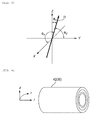
- FIG. 5 is a graph for illustrating an intersection angle between an orientation direction and an X-axis, an intersection angle between the orientation direction and a Y-axis, and an intersection angle between the orientation direction and a Z-axis.
- FIG. 6 is a graph for illustrating a circumferential direction, a thickness direction, and an axial direction of a cylindrical portion of the balloon.
- breaking stress is correlated with the number of molecular chains (the number of orientation distributions) per unit sectional area of the balloon forming material.
- a ratio between an occurrence of the rupture in the circumferential direction and an occurrence of the rupture in the axial direction is affected by the number of orientation distributions.
- the number of orientation distributions is related to anisotropy of polarizability, and the anisotropy of polarizability is related to anisotropy of refractive index (optical anisotropy). Accordingly, the number of orientation distributions can be measured by utilizing a phenomenon of birefringence.
- the number of orientation distributions is analyzed by measuring a difference (a degree of birefringence) between the two refracted lights and calculating refractive index.
- a comparison in terms of refractive index can be applied to a comparison of orientations under the same material and the same condition but is not suitable for a comparison between different types of resins, thereby being poor in versatility. Therefore, in the present embodiment, a definition is given regarding the physical property in which the rupture in the circumferential direction can be prevented by using the ratio of the number of orientation distributions.
- refractive index in a circumferential direction r refractive index in a thickness direction d, and refractive index in an axial direction 1 are respectively indicated as nr, nd, and nl, n x and n z required for calculating the number of orientation distributions in the circumferential direction
- the number of orientation distributions in the axial direction, and the number of orientation distributions in the thickness direction are calculated by the following Expressions by utilizing intrinsic refringence ⁇ n* which is a value of birefringence shown when molecules are oriented 100%.
- refractive index is calculated by measuring retardation (a phase difference) using a polarizing microscope.
- FIG. 7 is a flow chart for illustrating the method of manufacturing a balloon according to the embodiment of the present invention.
- the method of manufacturing a balloon according to the embodiment of the present invention includes a preforming step, a molding step, and a trimming step.
- a tubular parison which is a material (preform) of the balloon 30 and has a three-layer structure is molded through coextrusion.
- the molding step includes an arranging step, a heating/pressurizing step, a first stretching step, a second stretching step, an annealing step, and a taking-out step.
- the tubular parison is molded into a shape which substantially coincides with the outer shape of the balloon 30.
- an end portion of the molded tubular parison is cut, thereby obtaining the balloon 30.
- FIG. 8 is a cross-sectional view for illustrating the blow molding apparatus which is applied to a molding step shown in FIG. 7 .
- a blow molding apparatus 60 includes molding dies (blow molding dies) 62 and 66, and chuck portions 80 and 82.
- the molding dies 62 and 66 include cavity surfaces 64 and 68, heaters 70 and 72, and cooling jackets 74 and 76.
- the cavity surfaces 64 and 68 integrally correspond to the outer shape of the balloon 30.
- the cavity surfaces 64 and 68 exhibit the shapes which substantially coincide with the outer shape of the balloon 30.
- the heaters 70 and 72 are formed with sheet heaters and are used for increasing temperatures of the molding dies 62 and 66 so as to indirectly heat a tubular parison 20 which is arranged in an internal space between the cavity surfaces 64 and 68, and increasing the temperature until the tubular parison 20 is plasticized.
- the cooling jackets 74 and 76 are configured to be arranged on the outer circumference of the heaters 70 and 72, allowing a coolant to circulate.
- the coolant is used for indirectly cooling the tubular parison 20 which is arranged in the internal space between the cavity surfaces 64 and 68 by decreasing the temperatures of the molding dies 62 and 66.
- the coolant is liquid such as water or the like, or gas such as air or the like.
- the chuck portions 80 and 82 are arranged so as to be able to approach and be separated in the axial direction of the tubular parison 20.
- the chuck portions 80 and 82 are used for grasping an end portion 24 of the tubular parison 20.
- the chuck portion 80 includes an injection port 86
- the chuck portion 82 includes a load cell 84 and a discharge port 88.
- the injection port 86 is used for injecting a molding fluid into the tubular parison 20 so as to apply pressure to the inside of the tubular parison 20 (increase internal pressure).
- the discharge port 88 is used for discharging the molding fluid from the tubular parison 20 so as to return the inside of the tubular parison 20 to atmospheric pressure.
- the molding fluid is air or nitrogen.
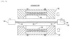
- FIG. 9 is a cross-sectional view for illustrating the arranging step shown in FIG. 7 .
- FIG. 10 is a cross-sectional view for illustrating the heating/pressurizing step shown in FIG. 7 .
- FIG. 11 is a cross-sectional view for illustrating the first stretching step shown in FIG. 7 .
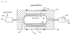
- FIG. 12 is a cross-sectional view for illustrating the timing of cessation of stretching in the first stretching step.
- FIG. 13 is a cross-sectional view for illustrating the second stretching step shown in FIG. 7 .
- FIG. 14 is a cross-sectional view for illustrating the annealing step shown in FIG. 7 .
- FIG. 15 is a cross-sectional view for illustrating the taking-out step shown in FIG. 7 .
- the cross section of the tubular parison 20 is simplified, thereby being shown as a single layer.
- the tubular parison 20 is held by the chuck portions 80 and 82, and is arranged in the internal space formed by the cavity surfaces 64 and 68 of the molding dies 62 and 66. Then molding clamping of the molding dies 62 and 66 is performed.
- the temperatures of the molding dies 62 and 66 are increased by operating the heaters 70 and 72 so as to indirectly heat the tubular parison 20 which is arranged in the internal space between the cavity surfaces 64 and 68.
- a molding medium is introduced.
- the molding medium passes through the injection port 86 of the chuck portion 80 and is injected into the tubular parison 20.
- pressure is applied to the inside of the tubular parison 20 (internal pressure is increased).
- the chuck portions 80 and 82 grasping the end portion 24 of the tubular parison 20 are separated from each other, and the tubular parison 20 is expanded by pressure applied to the inside of the tubular parison 20 while stretching the tubular parison 20 in the axial direction 1.
- stretching is executed at a high speed, thereby strongly causing the orientation of the tubular parison 20 in the axial direction to be uniform.
- the speed of stretching is set to cause the ratio of the number of orientation distributions to be less than 2.
- stretching is ceased the moment the expanded tubular parison 20 comes into contact with the cavity surfaces 64 and 68. Accordingly, abrasion caused by grazing against the cavity surfaces 64 and 68 is prevented from occurring.
- the presence/absence of contact is determined by a load change which is detected by the load cell 84 arranged in the chucks 80 and 82.
- the chuck portions 80 and 82 are separated farther away from each other, the end portion of the tubular parison 20 is expanded by pressure applied to the inside of the tubular parison 20 while the tubular parison 20 is stretched in the axial direction 1, thereby forming a tapered portion 26.
- the annealing step as illustrated in FIG. 14 , heating performed by the heaters 70 and 72 is ceased, thereafter introducing the coolant into the cooling jackets 74 and 76.
- the coolant indirectly cools off the tubular parison 20 by decreasing the temperatures of the molding dies 62 and 66.
- the molding fluid is discharged from the discharge port 88 so as to return the inside of the tubular parison 20 to atmospheric pressure, and molding opening of the molding dies 62 and 66 is performed, thereby taking out the tubular parison 20.
- the tubular parison 20 has a shape which substantially coincides with the outer shape of the balloon 30, and as described above, the end portion 24 is cut in the following trimming step, thereby obtaining the balloon 30.
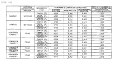
- FIG. 16 is a table showing relationships between the ratio of the number of orientation distributions and the rupture in the circumferential direction in Examples 1 and 2, and Comparison Examples 1 to 5.
- FIG. 17 is a plan view for illustrating measurement points shown in FIG. 16 .
- Examples 1 and 2 are manufactured by the method of manufacturing a balloon according to the embodiment of the present invention.
- Example 1 is a balloon having the three-layer structure with the length of 40 mm
- Example 2 is a balloon having the three-layer structure with the length of 30 mm.
- Comparison Examples 1 to 4 are balloons having the three-layer structures with the lengths of 200 mm
- Comparison Example 5 is a balloon having the two-layer structure with the length of 200 mm.
- Refractive index required for calculating the ratio of the number of orientation distributions is calculated by measuring retardation (a phase difference) of a test piece using a polarizing microscope. The test piece is adjusted by embedding the balloons of Examples 1 and 2 and Comparison Examples 1 to 5 in a resin 50, and performing thin slicing.
- a thin slice direction is the circumferential direction (a round slice direction) and the axial direction. As illustrated in FIG. 17 , the measurement points in the axial direction are a distal portion side P 1 , a center P 2 , and a proximal portion side P 3 of the cylindrical portion 42.
- the ratios of the numbers of orientation distributions are less than 2 throughout the total length of the cylindrical portion, and there is no occurrence of the rupture in the circumferential direction.
- the ratios of the numbers of orientation distributions are 2 or more throughout the total length of the cylindrical portion, and there is an occurrence of the rupture in the circumferential direction.
- the ratios of the numbers of orientation distributions are partially less than 2, and there is an occurrence of the rupture in the circumferential direction. Accordingly, in order to prevent the rupture in the circumferential direction from occurring, the ratio of the number of orientation distributions needs to be less than 2 throughout the total length of the cylindrical portion.
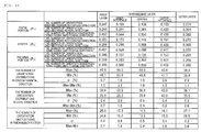
- FIGS. 18 and 19 are tables for illustrating fluctuation in the numbers of orientation distributions in Examples 3 and 4.
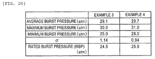
- FIG. 20 is a table for illustrating pressure resistance data of Examples 3 and 4.
- the numerical values are offset only, and a result similar to that of the numbers of orientation distributions is obtained. Therefore, in FIGS. 18 and 19 , calculation results of the ratios of the numbers of orientation distributions are not shown.
- Example 3 shows values smaller than those of Example 4. Compared to Example 4, pressure resistance is deteriorated.
- FIGS. 18 and 19 show that Example 3 has a greater standard deviation ⁇ of the number of orientation distributions, compared to Example 4.
- the standard deviation ⁇ of the number of orientation distributions (the ratio of the number of orientation distributions) is correlated with pressure resistance, and it is understood that as the standard deviation ⁇ becomes lower, pressure resistance improves further.
- the standard deviation ⁇ of the outer layer having the maximum strength ranges from 0.3% to 1.0%. Accordingly, fluctuation in the axial direction in the ratio of the numbers of orientation distributions in the layer having the maximum strength is preferably 1 or less in terms of the standard deviation.
- the balloon (the balloon in which the ratio of the number of orientation distributions calculated by dividing the number of orientation distributions of the cylindrical portion in the circumferential direction by the number of orientation distributions of the cylindrical portion in the axial direction is less than 2) having a physical property in which the rupture in the circumferential direction can be prevented.
- the balloon the balloon in which the rupture in the circumferential direction can be prevented from occurring, and the method of manufacturing the same.
- the medical catheter can be applied to an over-the-wire (OTW) type without being limited to a rapid exchange type.
- OGW over-the-wire
- the guide wire is structured to pass through from the distal end to the user' s hand. Therefore, replacement of the guide wire and operability become favorable.
- the load change of the chuck is not limited to the form of utilizing the load cell.
Landscapes
- Health & Medical Sciences (AREA)
- Engineering & Computer Science (AREA)
- Manufacturing & Machinery (AREA)
- Life Sciences & Earth Sciences (AREA)
- Heart & Thoracic Surgery (AREA)
- Mechanical Engineering (AREA)
- Pulmonology (AREA)
- Biophysics (AREA)
- Child & Adolescent Psychology (AREA)
- Anesthesiology (AREA)
- Biomedical Technology (AREA)
- Hematology (AREA)
- Animal Behavior & Ethology (AREA)
- General Health & Medical Sciences (AREA)
- Public Health (AREA)
- Veterinary Medicine (AREA)
- Physics & Mathematics (AREA)
- Thermal Sciences (AREA)
- Media Introduction/Drainage Providing Device (AREA)
Abstract
Description
- The present invention relates to a balloon and a method of manufacturing the same.
- In a balloon catheter, a dilatable balloon is installed at a distal end portion thereof. For example, the balloon catheter is used in order to dilate a stenosed portion or an obstructive portion so as to improve blood flow when stenosis or obstruction occurs in a blood vessel. The balloon has been configured to have strength and shock resistance able to withstand against an increase of internal pressure when a target partion is dilated.
- However, there exists a possibility of breakage of a balloon caused by an unexpected rapid increase of internal pressure or a shock due to unexpected contact with biological tissue which is hardened, that is, calcified, for example. As breakage of the balloon, a rupture in a circumferential direction and a rupture in an axial direction are assumed. Being different from the rupture in the axial direction, a fragment separated from the balloon is likely to occur in the rupture in the circumferential direction. Therefore, there is a need to prevent the rupture in the circumferential direction from occurring.
- The present invention has been made in order to solve the problem entailed in the conventional technology, and an object thereof is to provide a balloon in which the rupture in the circumferential direction can be prevented from occurring, and a method of manufacturing the same.
- In order to achieve the object, the present invention provides a balloon which is arranged on a medical catheter including: a dilatable cylindrical portion that is formed with a birefringent polymer material, in which a ratio of the number of orientation distributions calculated by dividing the number of orientation distributions of the cylindrical portion in a circumferential direction by the number of orientation distributions of the cylindrical portion in an axial direction is less than 2.
- Another aspect of the present invention for achieving the object is to provide a method of manufacturing a balloon which is arranged on a medical catheter including a molding step of performing blow molding of a tubular parison which is formed with a birefringent polymer material and molding a dilatable cylindrical portion of the balloon, in which in the molding step, the cylindrical portion is molded so as to cause a ratio of the number of orientation distributions calculated by dividing the number of orientation distributions of the cylindrical portion in a circumferential direction by the number of orientation distributions of the cylindrical portion in an axial direction to be less than 2.
- According to the present invention, it is possible to acquire a balloon (a balloon in which a ratio of the number of orientation distributions calculated by dividing the number of orientation distributions of a cylindrical portion in a circumferential direction by the number of orientation distributions of the cylindrical portion in an axial direction is less than 2) having a physical property in which a rupture in the circumferential direction can be prevented. In other words, it is possible to provide a balloon in which the rupture in the circumferential direction can be prevented from occurring, and a method of manufacturing the same.
- As necessary, the balloon (the cylindrical portion) can have a multi-layer structure made with polymer materials which are different from each other.
- It is preferable that fluctuation in the axial direction in the ratio of the number of orientation distributions in a layer having the maximum strength is 1 or less in terms of a standard deviation. In this case, pressure resistance can be improved.
- A medical catheter is a balloon catheter, for example. The balloon catheter can also be applied to a stent delivery system for causing a stent to indwell inside a human body.
- When a molding step includes a stretching step in which a heated tubular parison is expanded by pressure applied to the inside of the tubular parison while the heated tubular parison is stretched in the axial direction, the cylindrical portion can be molded so as to cause the ratio of the number of orientation distributions to be less than 2, by controlling a stretching speed.
- In the stretching step, when stretching is ceased the moment the expanded tubular parison comes into contact with a cavity surface of a blow molding die, abrasion caused by the expanded tubular parison grazing against the cavity surface can be prevented from occurring.
- When a tubular parison having the multi-layer structure made with the polymer materials which are different from each other is applied, it is possible to acquire the balloon (the cylindrical portion) having the multi-layer structure.
- Other objects, characteristics, and properties of the present invention become clear with reference to preferable embodiments exemplified in the following descriptions and accompanying drawings.
-
- [
FIG. 1] FIG. 1 is a side view for illustrating a balloon according to an embodiment of the present invention. - [
FIG. 2] FIG. 2 is a cross-sectional view taken along line II-II inFIG. 1 . - [
FIG. 3] FIG. 3 is a schematic diagram for illustrating a medical catheter applied with the balloon shown inFIG. 1 . - [
FIG. 4] FIG. 4 is a schematic diagram for illustrating another form of the medical catheter applied with the balloon shown inFIG. 1 . - [
FIG. 5] FIG. 5 is a graph for illustrating an intersection angle between an orientation direction and an X-axis, an intersection angle between the orientation direction and a Y-axis, and an intersection angle between the orientation direction and a Z-axis. - [
FIG. 6] FIG. 6 is a graph for illustrating a circumferential direction, a thickness direction, and an axial direction of a cylindrical portion of the balloon. - [
FIG. 7] FIG. 7 is a flow chart for illustrating a method of manufacturing a balloon according to the embodiment of the present invention. - [
FIG. 8] FIG. 8 is a cross-sectional view for illustrating a blow molding apparatus which is applied to a molding step shown inFIG. 7 . - [
FIG. 9] FIG. 9 is a cross-sectional view for illustrating an arranging step shown inFIG. 7 . - [
FIG. 10] FIG. 10 is a cross-sectional view for illustrating a heating/pressurizing step shown inFIG. 7 . - [
FIG. 11] FIG. 11 is a cross-sectional view for illustrating a first stretching step shown inFIG. 7 . - [
FIG. 12] FIG. 12 is a cross-sectional view for illustrating the timing of cessation of stretching in the first stretching step. - [
FIG. 13] FIG. 13 is a cross-sectional view for illustrating a second stretching step shown inFIG. 7 . - [
FIG. 14] FIG. 14 is a cross-sectional view for illustrating an annealing step shown inFIG. 7 . - [
FIG. 15] FIG. 15 is a cross-sectional view for illustrating a taking-out step shown inFIG. 7 . - [
FIG. 16] FIG. 16 is a table showing relationships between a ratio of the number of orientation distributions and a rupture in the circumferential direction in Examples 1 and 2, and Comparison Examples 1 to 5. - [
FIG. 17] FIG. 17 is a plan view for illustrating measurement points shown inFIG. 16 . - [
FIG. 18] FIG. 18 is a table for illustrating fluctuation in the numbers of orientation distributions in Example 3. - [
FIG. 19] FIG. 19 is a table for illustrating fluctuation in the numbers of orientation distributions in Example 4. - [
FIG. 20] FIG. 20 is a table for illustrating pressure resistance data of Examples 3 and 4. - Hereinafter, embodiments of the present invention will be described with reference to the drawings.
-
FIG. 1 is a side view for illustrating a balloon according to an embodiment of the present invention.FIG. 2 is a cross-sectional view taken along line II-II inFIG. 1 .FIG. 3 is a schematic diagram for illustrating a medical catheter applied with the balloon shown inFIG. 1 .FIG. 4 is a schematic diagram for illustrating another form of the medical catheter applied with the balloon shown inFIG. 1 . - A
balloon 30 according to the embodiment of the present invention is applied to aballoon catheter 10 shown inFIG. 3 , for example. Theballoon catheter 10 is the medical catheter which is applied to treatment of a portion where surgery cannot be easily performed, treatment aimed at being minimally invasive with respect to a human body, a cardiovascular contrast examination, or the like. The treatment of a portion where surgery cannot be easily performed is percutaneous transluminal coronary angioplasty (PTCA) which is applied to myocardial infarction and angina pectoris, for example. Theballoon catheter 10 is not limited to a form applied to a stenosed portion which occurs in a cardiac coronary artery. Theballoon catheter 10 can be applied to a stenosed portion which occurs in other blood vessels, the bile duct, the trachea, the esophagus, the urethra, or the like. - The
balloon catheter 10 is a rapid exchange (RX) type having a structure in which aguide wire 14 passes through only a distal portion. Theballoon catheter 10 includes adistal shaft 12 to which theballoon 30 is connected in a state where fluid tightness is maintained. Thedistal shaft 12 has a lumen for introducing a balloon dilation fluid. - As illustrated in
FIG. 1 , theballoon 30 includes acylindrical portion 42, and taperedportions 44 positioned on both sides of thecylindrical portion 42. As illustrated inFIG. 2 , theballoon 30 exhibits a three-layer structure including anouter layer 32, anintermediate layer 34, and aninner layer 36. Thecylindrical portion 42 has been configured to be dilatable by the balloon dilation fluid which is introduced via the lumen of thedistal shaft 12. - The
cylindrical portion 42 has a physical property in which a rupture in a circumferential direction can be prevented. As described below, the aforementioned physical property is a ratio of the number of orientation distributions calculated by dividing the number of orientation distributions of thecylindrical portion 42 in the circumferential direction by the number of orientation distributions of thecylindrical portion 42 in an axial direction (a ratio of the number of orientation distributions of thecylindrical portion 42 in the circumferential direction to the number of orientation distributions of thecylindrical portion 42 in the axial direction), and the ratio is calculated based on a refractive index and intrinsic birefringence of a balloon forming material. - The outer diameter of the
cylindrical portion 42 while being dilated is set to range from 1.0 mm to 10 mm, and is preferably set to range from 1.0 mm to 5.0 mm. The length of thecylindrical portion 42 ranges from 5 mm to 50 mm, and preferably ranges from 10 mm to 40 mm. The overall length of theballoon 30 ranges from 10 mm to 200 mm, and preferably ranges from 20 mm to 40 mm. - For example, the balloon forming material is a polymer material such as polyolefin, a cross-linked body of polyolefin, polyester, a polyester elastomer, polyvinyl chloride, polyurethane, a polyurethane elastomer, polyphenylene sulfide, polyamide, a polyamide elastomer, a fluorine resin, and the like; silicone rubber; and latex rubber. For example, polyester is polyethylene terephthalate.
- Polyamide is not particularly limited as long as the polyamide is a polymer having an amide bond. For example, the polyamide is a homopolymer such as polycaprolactam (nylon 6), polyhexamethylene adipamide (nylon 66), polyundecanolactam (nylon 11), polydodecanolactam (nylon 12), and the like. For example, the polyamide elastomer is a block copolymer having nylon 6,
nylon 66, nylon 11,nylon 12, or the like as a hard segment, and having polyalkylene glycol, polytetramethylene ether glycol, polyether, aliphatic polyester, or the like as a soft segment. - In the present embodiment, from a viewpoint of appropriate balance between flexibility and strength, the
outer layer 32 and theinner layer 36 are formed of a polyamide elastomer having polyamide 12 (nylon 12) and polytetramethylene ether glycol as a hard segment and a soft segment, and theintermediate layer 34 is formed ofPA 12. - The
balloon 30 is not limited to a form having the three-layer structure. Theballoon 30 can have a single (single layer) structure, a two-layer structure, or a structure of four or more layers. - The medical catheter applied with the
balloon 30 is not limited to theballoon catheter 10. For example, it is possible to apply to astent delivery system 10A shown inFIG. 4 . Thestent delivery system 10A has astent 16 which is arranged on the outer circumference of theballoon 30. For example, thestent delivery system 10A is applied to treatment aimed at preventing restenosis after performing percutaneous transluminal coronary angioplasty (PTCA). - The
stent 16 is a substance indwelling inside a living body for retaining a lumen by coming into close contact with the inner surface of a stenosed portion so as to indwell therein. Thestent 16 has been configured to be expandable. Theballoon 30 is configured to expand thestent 16 which is arranged at the outer circumference thereof so as to increase in diameter. Thestent 16 is formed with a material having biocompatibility. For example, the material having biocompatibility is a nickel-titanium alloy, a cobalt-chromium alloy, stainless steel, iron, titanium, aluminum, tin, and a zinc-tungsten alloy. - Subsequently, detailed descriptions will be given regarding a method of calculating the number of orientation distributions in the circumferential direction and the number of orientation distributions in the axial direction related to a physical property in which the rupture in the circumferential direction can be prevented.
-
FIG. 5 is a graph for illustrating an intersection angle between an orientation direction and an X-axis, an intersection angle between the orientation direction and a Y-axis, and an intersection angle between the orientation direction and a Z-axis.FIG. 6 is a graph for illustrating a circumferential direction, a thickness direction, and an axial direction of a cylindrical portion of the balloon. - When a rupture of the cylindrical portion of the balloon occurs due to ductile fracture, breaking stress is correlated with the number of molecular chains (the number of orientation distributions) per unit sectional area of the balloon forming material. A ratio between an occurrence of the rupture in the circumferential direction and an occurrence of the rupture in the axial direction is affected by the number of orientation distributions. The number of orientation distributions is related to anisotropy of polarizability, and the anisotropy of polarizability is related to anisotropy of refractive index (optical anisotropy). Accordingly, the number of orientation distributions can be measured by utilizing a phenomenon of birefringence.
- For example, when light is incident on an optical isomer, the light is divided into two refracted lights oscillating in directions perpendicular to each other. Therefore, the number of orientation distributions is analyzed by measuring a difference (a degree of birefringence) between the two refracted lights and calculating refractive index. However, a comparison in terms of refractive index can be applied to a comparison of orientations under the same material and the same condition but is not suitable for a comparison between different types of resins, thereby being poor in versatility. Therefore, in the present embodiment, a definition is given regarding the physical property in which the rupture in the circumferential direction can be prevented by using the ratio of the number of orientation distributions.
- Specifically, as illustrated in
FIG. 5 , when an intersection angle between an orientation direction D and the X-axis, an intersection angle between the orientation direction D and the Y-axis, and an intersection angle between the orientation direction D and the Z-axis are respectively indicated as φx, φy, and φz, the number of orientation distributions in the circumferential direction, the number of orientation distributions in the axial direction, and the number of orientation distributions in the thickness direction are defined by the following Expressions. - [Expressions 1]


(In the Expressions,cos 2 Ø x indicates the number of orientation distributions in the circumferential direction,cos 2 Ø y indicates the number of orientation distributions in the thickness direction, andcos 2 Ø z indicates the number of orientation distributions in the axial direction.) - As illustrated in
FIG. 6 , when refractive index in a circumferential direction r, refractive index in a thickness direction d, and refractive index in anaxial direction 1 are respectively indicated as nr, nd, and nl, nx and nz required for calculating the number of orientation distributions in the circumferential direction, the number of orientation distributions in the axial direction, and the number of orientation distributions in the thickness direction are calculated by the following Expressions by utilizing intrinsic refringence Δn* which is a value of birefringence shown when molecules are oriented 100%. For example, refractive index is calculated by measuring retardation (a phase difference) using a polarizing microscope. - [Expressions 2]


(In the Expressions, n2 indicates average refractive index.) - Subsequently, a method of manufacturing a balloon according to the embodiment of the present invention will be described.
-
FIG. 7 is a flow chart for illustrating the method of manufacturing a balloon according to the embodiment of the present invention. - As illustrated in
FIG. 7 , the method of manufacturing a balloon according to the embodiment of the present invention includes a preforming step, a molding step, and a trimming step. - In the preforming step, for example, a tubular parison which is a material (preform) of the
balloon 30 and has a three-layer structure is molded through coextrusion. - The molding step includes an arranging step, a heating/pressurizing step, a first stretching step, a second stretching step, an annealing step, and a taking-out step. By performing blow molding, the tubular parison is molded into a shape which substantially coincides with the outer shape of the
balloon 30. - In the trimming step, for example, an end portion of the molded tubular parison is cut, thereby obtaining the
balloon 30. - Subsequently, a blow molding apparatus applied to the molding step will be described.
-
FIG. 8 is a cross-sectional view for illustrating the blow molding apparatus which is applied to a molding step shown inFIG. 7 . - A
blow molding apparatus 60 includes molding dies (blow molding dies) 62 and 66, and chuckportions heaters jackets - The cavity surfaces 64 and 68 integrally correspond to the outer shape of the
balloon 30. When molding clamping of the molding dies 62 and 66 is performed, the cavity surfaces 64 and 68 exhibit the shapes which substantially coincide with the outer shape of theballoon 30. - For example, the
heaters tubular parison 20 which is arranged in an internal space between the cavity surfaces 64 and 68, and increasing the temperature until thetubular parison 20 is plasticized. - The cooling
jackets heaters tubular parison 20 which is arranged in the internal space between the cavity surfaces 64 and 68 by decreasing the temperatures of the molding dies 62 and 66. For example, the coolant is liquid such as water or the like, or gas such as air or the like. - The
chuck portions tubular parison 20. Thechuck portions end portion 24 of thetubular parison 20. Thechuck portion 80 includes aninjection port 86, and thechuck portion 82 includes aload cell 84 and adischarge port 88. Theinjection port 86 is used for injecting a molding fluid into thetubular parison 20 so as to apply pressure to the inside of the tubular parison 20 (increase internal pressure). Thedischarge port 88 is used for discharging the molding fluid from thetubular parison 20 so as to return the inside of thetubular parison 20 to atmospheric pressure. For example, the molding fluid is air or nitrogen. - Subsequently, each step of the method of manufacturing a balloon according to the embodiment of the present invention will be sequentially described in detail.
-
FIG. 9 is a cross-sectional view for illustrating the arranging step shown inFIG. 7 .FIG. 10 is a cross-sectional view for illustrating the heating/pressurizing step shown inFIG. 7 .FIG. 11 is a cross-sectional view for illustrating the first stretching step shown inFIG. 7 .FIG. 12 is a cross-sectional view for illustrating the timing of cessation of stretching in the first stretching step.FIG. 13 is a cross-sectional view for illustrating the second stretching step shown inFIG. 7 .FIG. 14 is a cross-sectional view for illustrating the annealing step shown inFIG. 7 .FIG. 15 is a cross-sectional view for illustrating the taking-out step shown inFIG. 7 . InFIGS. 9 to 15 , the cross section of thetubular parison 20 is simplified, thereby being shown as a single layer. - In the arranging step, as illustrated in
FIG. 9 , thetubular parison 20 is held by thechuck portions - In the heating/pressurizing step, as illustrated in
FIG. 10 , the temperatures of the molding dies 62 and 66 are increased by operating theheaters tubular parison 20 which is arranged in the internal space between the cavity surfaces 64 and 68. As the temperature is increased until thetubular parison 20 is plasticized, a molding medium is introduced. The molding medium passes through theinjection port 86 of thechuck portion 80 and is injected into thetubular parison 20. Then, pressure is applied to the inside of the tubular parison 20 (internal pressure is increased). - In the first stretching step, as illustrated in
FIG. 11 , thechuck portions end portion 24 of thetubular parison 20 are separated from each other, and thetubular parison 20 is expanded by pressure applied to the inside of thetubular parison 20 while stretching thetubular parison 20 in theaxial direction 1. In this case, stretching is executed at a high speed, thereby strongly causing the orientation of thetubular parison 20 in the axial direction to be uniform. The speed of stretching is set to cause the ratio of the number of orientation distributions to be less than 2. - As illustrated in
FIG. 12 , stretching is ceased the moment the expandedtubular parison 20 comes into contact with the cavity surfaces 64 and 68. Accordingly, abrasion caused by grazing against the cavity surfaces 64 and 68 is prevented from occurring. The presence/absence of contact is determined by a load change which is detected by theload cell 84 arranged in thechucks - In the second stretching step, as illustrated in
FIG. 13 , thechuck portions tubular parison 20 is expanded by pressure applied to the inside of thetubular parison 20 while thetubular parison 20 is stretched in theaxial direction 1, thereby forming a taperedportion 26. - In the annealing step, as illustrated in
FIG. 14 , heating performed by theheaters jackets tubular parison 20 by decreasing the temperatures of the molding dies 62 and 66. - In the taking-out step, as illustrated in
FIG. 15 , the molding fluid is discharged from thedischarge port 88 so as to return the inside of thetubular parison 20 to atmospheric pressure, and molding opening of the molding dies 62 and 66 is performed, thereby taking out thetubular parison 20. In this case, excluding the shape of theend portion 24, thetubular parison 20 has a shape which substantially coincides with the outer shape of theballoon 30, and as described above, theend portion 24 is cut in the following trimming step, thereby obtaining theballoon 30. - Subsequently, a relationship between the ratio of the number of orientation distributions and the rupture in the circumferential direction will be described.
-
FIG. 16 is a table showing relationships between the ratio of the number of orientation distributions and the rupture in the circumferential direction in Examples 1 and 2, and Comparison Examples 1 to 5.FIG. 17 is a plan view for illustrating measurement points shown inFIG. 16 . - Examples 1 and 2 are manufactured by the method of manufacturing a balloon according to the embodiment of the present invention. Example 1 is a balloon having the three-layer structure with the length of 40 mm, and Example 2 is a balloon having the three-layer structure with the length of 30 mm. Comparison Examples 1 to 4 are balloons having the three-layer structures with the lengths of 200 mm, and Comparison Example 5 is a balloon having the two-layer structure with the length of 200 mm.
- Refractive index required for calculating the ratio of the number of orientation distributions is calculated by measuring retardation (a phase difference) of a test piece using a polarizing microscope. The test piece is adjusted by embedding the balloons of Examples 1 and 2 and Comparison Examples 1 to 5 in a
resin 50, and performing thin slicing. A thin slice direction is the circumferential direction (a round slice direction) and the axial direction. As illustrated inFIG. 17 , the measurement points in the axial direction are a distal portion side P1, a center P2, and a proximal portion side P3 of thecylindrical portion 42. - As illustrated in
FIG. 16 , in Examples 1 and 2, the ratios of the numbers of orientation distributions are less than 2 throughout the total length of the cylindrical portion, and there is no occurrence of the rupture in the circumferential direction. Meanwhile, in Comparison Examples 3 to 5, the ratios of the numbers of orientation distributions are 2 or more throughout the total length of the cylindrical portion, and there is an occurrence of the rupture in the circumferential direction. In Comparison Examples 1 and 2, the ratios of the numbers of orientation distributions are partially less than 2, and there is an occurrence of the rupture in the circumferential direction. Accordingly, in order to prevent the rupture in the circumferential direction from occurring, the ratio of the number of orientation distributions needs to be less than 2 throughout the total length of the cylindrical portion. - Subsequently, a relationship between fluctuation in the ratio of the number of orientation distributions and pressure resistance will be described.
-
FIGS. 18 and19 are tables for illustrating fluctuation in the numbers of orientation distributions in Examples 3 and 4.FIG. 20 is a table for illustrating pressure resistance data of Examples 3 and 4. The numbers of orientation distributions shown inFIGS. 18 to 20 are values acquired under the condition of n = 30, and fluctuation is indicated in terms of a standard deviation σ. In the ratios of the numbers of orientation distributions, the numerical values are offset only, and a result similar to that of the numbers of orientation distributions is obtained. Therefore, inFIGS. 18 and19 , calculation results of the ratios of the numbers of orientation distributions are not shown. - As illustrated in
FIG. 20 , with regard to the average burst pressure, the maximum burst pressure, the minimum burst pressure, and the rated burst pressure, Example 3 shows values smaller than those of Example 4. Compared to Example 4, pressure resistance is deteriorated. - Meanwhile,
FIGS. 18 and19 show that Example 3 has a greater standard deviation σ of the number of orientation distributions, compared to Example 4. In other words, the standard deviation σ of the number of orientation distributions (the ratio of the number of orientation distributions) is correlated with pressure resistance, and it is understood that as the standard deviation σ becomes lower, pressure resistance improves further. - In the balloon having a multi-layer structure, pressure resistance is significantly affected depending on the layer having the maximum strength. In Examples 3 and 4, the standard deviation σ of the outer layer having the maximum strength ranges from 0.3% to 1.0%. Accordingly, fluctuation in the axial direction in the ratio of the numbers of orientation distributions in the layer having the maximum strength is preferably 1 or less in terms of the standard deviation.
- As describe above, in the present embodiment, it is possible to acquire the balloon (the balloon in which the ratio of the number of orientation distributions calculated by dividing the number of orientation distributions of the cylindrical portion in the circumferential direction by the number of orientation distributions of the cylindrical portion in the axial direction is less than 2) having a physical property in which the rupture in the circumferential direction can be prevented. In other words, it is possible to provide the balloon in which the rupture in the circumferential direction can be prevented from occurring, and the method of manufacturing the same.
- The present invention is not limited to the above-described embodiment, and various changes and modifications can be made within the scope of Claims. For example, the medical catheter can be applied to an over-the-wire (OTW) type without being limited to a rapid exchange type. In this case, the guide wire is structured to pass through from the distal end to the user' s hand. Therefore, replacement of the guide wire and operability become favorable. The load change of the chuck is not limited to the form of utilizing the load cell.
-
- 10
- balloon catheter,
- 10A
- stent delivery system,
- 12
- distal shaft,
- 14
- guide wire,
- 16
- stent,
- 20
- tubular parison,
- 24
- end portion,
- 26
- tapered portion,
- 30
- balloon,
- 32
- outer layer,
- 34
- intermediate layer,
- 36
- inner layer,
- 42
- cylindrical portion,
- 44
- tapered portion,
- 50
- resin,
- 60
- blow molding apparatus,
- 62, 66
- molding die (blow molding die),
- 64, 68
- cavity surface,
- 70, 72
- heater,
- 74, 76
- cooling jacket,
- 80, 82
- chuck portion,
- 84
- load cell,
- 86
- injection port,
- 88
- discharge port,
- d
- thickness direction,
- 1
- axial direction,
- P1
- distal portion side of cylindrical portion,
- P2
- center P of cylindrical portion,
- P3
- proximal portion side P of cylindrical portion,
- r
- circumferential direction, and
- φx, φy, φz
- intersection angle.
Claims (10)
- A balloon which is arranged on a medical catheter, comprising:a dilatable cylindrical portion that is formed with a birefringent polymer material,wherein a ratio of the number of orientation distributions calculated by dividing the number of orientation distributions of the cylindrical portion in a circumferential direction by the number of orientation distributions of the cylindrical portion in an axial direction is less than 2.
- The balloon according to Claim 1,
wherein the cylindrical portion has a multi-layer structure made with the polymer materials which are different from each other. - The balloon according to Claim 2,
wherein fluctuation in the axial direction in the ratio of the number of orientation distributions in a layer having the maximum strength is 1 or less in terms of a standard deviation. - The balloon according to any one of Claims 1 to 4,
wherein the medical catheter is a balloon catheter. - The balloon according to Claim 4,
wherein the balloon catheter is used in order to cause a stent to indwell inside a human body. - A method of manufacturing a balloon which is arranged on a medical catheter, comprising:a molding step of performing blow molding of a tubular parison which is formed with a birefringent polymer material and molding a dilatable cylindrical portion of the balloon,wherein in the molding step, the cylindrical portion is molded so as to cause a ratio of the number of orientation distributions calculated by dividing the number of orientation distributions of the cylindrical portion in a circumferential direction by the number of orientation distributions of the cylindrical portion in an axial direction to be less than 2.
- The method of manufacturing a balloon according to Claim 6,
wherein the molding step includes a stretching step in which the heated parison is expanded by pressure applied to the inside of the tubular parison while the heated tubular parison is stretched in the axial direction, and
wherein the cylindrical portion is molded so as to cause the ratio of the number of orientation distributions to be less than 2, by controlling a stretching speed. - The method of manufacturing a balloon according to Claim 7,
wherein in the stretching step, stretching is ceased the moment the expanded tubular parison comes into contact with a cavity surface of a blow molding die. - The method of manufacturing a balloon according to any one of Claims 6 to 8,
wherein the tubular parison has a multi-layer structure made with the polymer materials which are different from each other, and
wherein the cylindrical portion of the balloon which is molded from the tubular parison exhibits the multi-layer structure. - The method of manufacturing a balloon according to Claim 9,
wherein in the molding step, the cylindrical portion is molded so as to cause fluctuation in the axial direction in the ratio of the number of orientation distributions in a layer having the maximum strength to be 1 or less in terms of a standard deviation.
Applications Claiming Priority (1)
| Application Number | Priority Date | Filing Date | Title |
|---|---|---|---|
| PCT/JP2013/056793 WO2014141382A1 (en) | 2013-03-12 | 2013-03-12 | Balloon and production method for same |
Publications (3)
| Publication Number | Publication Date |
|---|---|
| EP2974766A1 true EP2974766A1 (en) | 2016-01-20 |
| EP2974766A4 EP2974766A4 (en) | 2016-12-07 |
| EP2974766B1 EP2974766B1 (en) | 2022-09-21 |
Family
ID=51536085
Family Applications (1)
| Application Number | Title | Priority Date | Filing Date |
|---|---|---|---|
| EP13878235.4A Active EP2974766B1 (en) | 2013-03-12 | 2013-03-12 | Balloon and production method for same |
Country Status (5)
| Country | Link |
|---|---|
| US (1) | US9844651B2 (en) |
| EP (1) | EP2974766B1 (en) |
| JP (1) | JP6014242B2 (en) |
| ES (1) | ES2929182T3 (en) |
| WO (1) | WO2014141382A1 (en) |
Cited By (2)
| Publication number | Priority date | Publication date | Assignee | Title |
|---|---|---|---|---|
| CN106512184A (en) * | 2016-12-09 | 2017-03-22 | 江苏常美医疗器械有限公司 | Rapid catheter clamping and inflating device |
| EP4338766A4 (en) * | 2021-05-10 | 2025-05-14 | Kaneka Corporation | Balloon for balloon catheter and method for producing a balloon catheter |
Families Citing this family (12)
| Publication number | Priority date | Publication date | Assignee | Title |
|---|---|---|---|---|
| WO2007075585A2 (en) | 2005-12-16 | 2007-07-05 | Interface Associates, Inc. | Multi-layer balloons for medical applications and methods for manufacturing the same |
| US20160114141A1 (en) | 2014-10-27 | 2016-04-28 | Interface Associates, Inc. | Methods of manufacturing nested balloons utilizing pressurized constrained annealing |
| US20160346522A1 (en) * | 2015-06-01 | 2016-12-01 | Covidien Lp | Balloon for medical device |
| US20180280966A1 (en) * | 2015-11-25 | 2018-10-04 | Coming Incorporated | Unitary serological pipette and methods of producing the same |
| CN106513488B (en) * | 2016-12-09 | 2018-03-13 | 江苏常美医疗器械有限公司 | balloon forming machine |
| PL3634714T3 (en) | 2017-05-25 | 2022-10-10 | Corning Incorporated | Methods of forming unitary serological pipettes |
| KR102072058B1 (en) * | 2018-01-02 | 2020-01-31 | 아이메디컴(주) | Balloon manufacturing jig for catheter and balloon manufacturing method using the same |
| US11724438B2 (en) * | 2020-03-23 | 2023-08-15 | Steer Medical Inc. | Method and system for stretching a tubular material, over a mandrel |
| US12186508B2 (en) * | 2021-04-14 | 2025-01-07 | The Board Of Trustees Of The University Of Arkansas | Patient specific medical balloon forming machine and system |
| JPWO2023176182A1 (en) * | 2022-03-14 | 2023-09-21 | ||
| WO2025204640A1 (en) * | 2024-03-28 | 2025-10-02 | 株式会社カネカ | Medical balloon and catheter |
| WO2025204639A1 (en) * | 2024-03-28 | 2025-10-02 | 株式会社カネカ | Medical balloon and catheter |
Family Cites Families (9)
| Publication number | Priority date | Publication date | Assignee | Title |
|---|---|---|---|---|
| US6004339A (en) * | 1996-11-13 | 1999-12-21 | Angiodynamics Incorporated | Balloon catheter with multiple distensibilities |
| JP3503417B2 (en) * | 1997-05-15 | 2004-03-08 | 鐘淵化学工業株式会社 | Balloon catheter and method of manufacturing balloon used therein |
| US6242063B1 (en) * | 1997-09-10 | 2001-06-05 | Scimed Life Systems, Inc. | Balloons made from liquid crystal polymer blends |
| US6946092B1 (en) * | 2001-09-10 | 2005-09-20 | Scimed Life Systems, Inc. | Medical balloon |
| JP2004298354A (en) * | 2003-03-31 | 2004-10-28 | Nippon Zeon Co Ltd | Inflation balloon and balloon catheter having the same |
| JP2005305187A (en) * | 2005-07-07 | 2005-11-04 | Kaneka Corp | Catheter balloon and its manufacturing method |
| WO2007075585A2 (en) * | 2005-12-16 | 2007-07-05 | Interface Associates, Inc. | Multi-layer balloons for medical applications and methods for manufacturing the same |
| US8703260B2 (en) * | 2010-09-14 | 2014-04-22 | Abbott Cardiovascular Systems Inc. | Catheter balloon and method for forming same |
| JP2012066008A (en) * | 2010-09-27 | 2012-04-05 | Terumo Corp | Multiple structure balloon and method for manufacturing the same |
-
2013
- 2013-03-12 WO PCT/JP2013/056793 patent/WO2014141382A1/en not_active Ceased
- 2013-03-12 JP JP2015505123A patent/JP6014242B2/en active Active
- 2013-03-12 EP EP13878235.4A patent/EP2974766B1/en active Active
- 2013-03-12 ES ES13878235T patent/ES2929182T3/en active Active
-
2015
- 2015-09-02 US US14/842,864 patent/US9844651B2/en active Active
Cited By (3)
| Publication number | Priority date | Publication date | Assignee | Title |
|---|---|---|---|---|
| CN106512184A (en) * | 2016-12-09 | 2017-03-22 | 江苏常美医疗器械有限公司 | Rapid catheter clamping and inflating device |
| CN106512184B (en) * | 2016-12-09 | 2022-06-07 | 江苏常美医疗器械有限公司 | Quick clamping and inflating device for conduit |
| EP4338766A4 (en) * | 2021-05-10 | 2025-05-14 | Kaneka Corporation | Balloon for balloon catheter and method for producing a balloon catheter |
Also Published As
| Publication number | Publication date |
|---|---|
| EP2974766B1 (en) | 2022-09-21 |
| JP6014242B2 (en) | 2016-10-25 |
| WO2014141382A1 (en) | 2014-09-18 |
| JPWO2014141382A1 (en) | 2017-02-16 |
| EP2974766A4 (en) | 2016-12-07 |
| ES2929182T3 (en) | 2022-11-25 |
| US9844651B2 (en) | 2017-12-19 |
| US20150367109A1 (en) | 2015-12-24 |
Similar Documents
| Publication | Publication Date | Title |
|---|---|---|
| EP2974766B1 (en) | Balloon and production method for same | |
| US8703260B2 (en) | Catheter balloon and method for forming same | |
| EP1120129B1 (en) | Balloon catheter | |
| US7029732B2 (en) | Medical device balloons with improved strength properties and processes for producing same | |
| WO2015122101A1 (en) | Balloon, and production method therefor | |
| WO2008073695A2 (en) | Dual-layer medical balloons | |
| US20090254113A1 (en) | Dilatation balloon with ridges and methods | |
| US20240075258A1 (en) | Balloon for balloon catheter and method of manufacturing balloon catheter | |
| EP2796162A1 (en) | Production method for expansion balloon | |
| WO2006126311A1 (en) | Balloon and balloon catheter | |
| JP4815657B2 (en) | Medical polymer blend material and medical balloon using this material | |
| WO2006086161A1 (en) | Hybrid mold for a catheter balloon and method of manufacturing such a balloon | |
| EP1976574A2 (en) | Dual-layer medical balloons | |
| JP2004298354A (en) | Inflation balloon and balloon catheter having the same | |
| EP4570296A1 (en) | Balloon catheter | |
| JP4967258B2 (en) | Balloon and balloon catheter | |
| JP6078371B2 (en) | Method for manufacturing balloon for balloon catheter | |
| JP4922498B2 (en) | Balloon parison | |
| JP4420549B2 (en) | Parison for balloon catheter | |
| WO2023176182A1 (en) | Balloon for balloon catheters | |
| US7645498B2 (en) | Balloon catheter formed of random copolymerized nylons | |
| JP2003326589A (en) | Method for manufacturing balloon and method for manufacturing catheter balloon using the same | |
| JP2001120656A (en) | Single lumen tube and catheter balloon |
Legal Events
| Date | Code | Title | Description |
|---|---|---|---|
| PUAI | Public reference made under article 153(3) epc to a published international application that has entered the european phase |
Free format text: ORIGINAL CODE: 0009012 |
|
| 17P | Request for examination filed |
Effective date: 20150824 |
|
| AK | Designated contracting states |
Kind code of ref document: A1 Designated state(s): AL AT BE BG CH CY CZ DE DK EE ES FI FR GB GR HR HU IE IS IT LI LT LU LV MC MK MT NL NO PL PT RO RS SE SI SK SM TR |
|
| AX | Request for extension of the european patent |
Extension state: BA ME |
|
| DAX | Request for extension of the european patent (deleted) | ||
| A4 | Supplementary search report drawn up and despatched |
Effective date: 20161104 |
|
| RIC1 | Information provided on ipc code assigned before grant |
Ipc: B29C 49/22 20060101ALI20161028BHEP Ipc: B29C 49/64 20060101ALI20161028BHEP Ipc: B29L 31/00 20060101ALI20161028BHEP Ipc: A61M 25/10 20060101AFI20161028BHEP Ipc: B29C 49/18 20060101ALI20161028BHEP Ipc: A61F 2/958 20130101ALI20161028BHEP Ipc: B29C 49/78 20060101ALI20161028BHEP |
|
| STAA | Information on the status of an ep patent application or granted ep patent |
Free format text: STATUS: EXAMINATION IS IN PROGRESS |
|
| 17Q | First examination report despatched |
Effective date: 20170713 |
|
| GRAP | Despatch of communication of intention to grant a patent |
Free format text: ORIGINAL CODE: EPIDOSNIGR1 |
|
| STAA | Information on the status of an ep patent application or granted ep patent |
Free format text: STATUS: GRANT OF PATENT IS INTENDED |
|
| INTG | Intention to grant announced |
Effective date: 20220422 |
|
| GRAS | Grant fee paid |
Free format text: ORIGINAL CODE: EPIDOSNIGR3 |
|
| GRAA | (expected) grant |
Free format text: ORIGINAL CODE: 0009210 |
|
| STAA | Information on the status of an ep patent application or granted ep patent |
Free format text: STATUS: THE PATENT HAS BEEN GRANTED |
|
| AK | Designated contracting states |
Kind code of ref document: B1 Designated state(s): AL AT BE BG CH CY CZ DE DK EE ES FI FR GB GR HR HU IE IS IT LI LT LU LV MC MK MT NL NO PL PT RO RS SE SI SK SM TR |
|
| REG | Reference to a national code |
Ref country code: GB Ref legal event code: FG4D |
|
| REG | Reference to a national code |
Ref country code: CH Ref legal event code: EP |
|
| REG | Reference to a national code |
Ref country code: IE Ref legal event code: FG4D |
|
| REG | Reference to a national code |
Ref country code: DE Ref legal event code: R096 Ref document number: 602013082562 Country of ref document: DE |
|
| REG | Reference to a national code |
Ref country code: AT Ref legal event code: REF Ref document number: 1519656 Country of ref document: AT Kind code of ref document: T Effective date: 20221015 |
|
| REG | Reference to a national code |
Ref country code: NL Ref legal event code: FP |
|
| REG | Reference to a national code |
Ref country code: ES Ref legal event code: FG2A Ref document number: 2929182 Country of ref document: ES Kind code of ref document: T3 Effective date: 20221125 |
|
| REG | Reference to a national code |
Ref country code: LT Ref legal event code: MG9D |
|
| PG25 | Lapsed in a contracting state [announced via postgrant information from national office to epo] |
Ref country code: SE Free format text: LAPSE BECAUSE OF FAILURE TO SUBMIT A TRANSLATION OF THE DESCRIPTION OR TO PAY THE FEE WITHIN THE PRESCRIBED TIME-LIMIT Effective date: 20220921 Ref country code: RS Free format text: LAPSE BECAUSE OF FAILURE TO SUBMIT A TRANSLATION OF THE DESCRIPTION OR TO PAY THE FEE WITHIN THE PRESCRIBED TIME-LIMIT Effective date: 20220921 Ref country code: NO Free format text: LAPSE BECAUSE OF FAILURE TO SUBMIT A TRANSLATION OF THE DESCRIPTION OR TO PAY THE FEE WITHIN THE PRESCRIBED TIME-LIMIT Effective date: 20221221 Ref country code: LV Free format text: LAPSE BECAUSE OF FAILURE TO SUBMIT A TRANSLATION OF THE DESCRIPTION OR TO PAY THE FEE WITHIN THE PRESCRIBED TIME-LIMIT Effective date: 20220921 Ref country code: LT Free format text: LAPSE BECAUSE OF FAILURE TO SUBMIT A TRANSLATION OF THE DESCRIPTION OR TO PAY THE FEE WITHIN THE PRESCRIBED TIME-LIMIT Effective date: 20220921 Ref country code: FI Free format text: LAPSE BECAUSE OF FAILURE TO SUBMIT A TRANSLATION OF THE DESCRIPTION OR TO PAY THE FEE WITHIN THE PRESCRIBED TIME-LIMIT Effective date: 20220921 |
|
| REG | Reference to a national code |
Ref country code: AT Ref legal event code: MK05 Ref document number: 1519656 Country of ref document: AT Kind code of ref document: T Effective date: 20220921 |
|
| PG25 | Lapsed in a contracting state [announced via postgrant information from national office to epo] |
Ref country code: HR Free format text: LAPSE BECAUSE OF FAILURE TO SUBMIT A TRANSLATION OF THE DESCRIPTION OR TO PAY THE FEE WITHIN THE PRESCRIBED TIME-LIMIT Effective date: 20220921 Ref country code: GR Free format text: LAPSE BECAUSE OF FAILURE TO SUBMIT A TRANSLATION OF THE DESCRIPTION OR TO PAY THE FEE WITHIN THE PRESCRIBED TIME-LIMIT Effective date: 20221222 |
|
| PG25 | Lapsed in a contracting state [announced via postgrant information from national office to epo] |
Ref country code: SM Free format text: LAPSE BECAUSE OF FAILURE TO SUBMIT A TRANSLATION OF THE DESCRIPTION OR TO PAY THE FEE WITHIN THE PRESCRIBED TIME-LIMIT Effective date: 20220921 Ref country code: RO Free format text: LAPSE BECAUSE OF FAILURE TO SUBMIT A TRANSLATION OF THE DESCRIPTION OR TO PAY THE FEE WITHIN THE PRESCRIBED TIME-LIMIT Effective date: 20220921 Ref country code: PT Free format text: LAPSE BECAUSE OF FAILURE TO SUBMIT A TRANSLATION OF THE DESCRIPTION OR TO PAY THE FEE WITHIN THE PRESCRIBED TIME-LIMIT Effective date: 20230123 Ref country code: CZ Free format text: LAPSE BECAUSE OF FAILURE TO SUBMIT A TRANSLATION OF THE DESCRIPTION OR TO PAY THE FEE WITHIN THE PRESCRIBED TIME-LIMIT Effective date: 20220921 Ref country code: AT Free format text: LAPSE BECAUSE OF FAILURE TO SUBMIT A TRANSLATION OF THE DESCRIPTION OR TO PAY THE FEE WITHIN THE PRESCRIBED TIME-LIMIT Effective date: 20220921 |
|
| PG25 | Lapsed in a contracting state [announced via postgrant information from national office to epo] |
Ref country code: SK Free format text: LAPSE BECAUSE OF FAILURE TO SUBMIT A TRANSLATION OF THE DESCRIPTION OR TO PAY THE FEE WITHIN THE PRESCRIBED TIME-LIMIT Effective date: 20220921 Ref country code: PL Free format text: LAPSE BECAUSE OF FAILURE TO SUBMIT A TRANSLATION OF THE DESCRIPTION OR TO PAY THE FEE WITHIN THE PRESCRIBED TIME-LIMIT Effective date: 20220921 Ref country code: IS Free format text: LAPSE BECAUSE OF FAILURE TO SUBMIT A TRANSLATION OF THE DESCRIPTION OR TO PAY THE FEE WITHIN THE PRESCRIBED TIME-LIMIT Effective date: 20230121 Ref country code: EE Free format text: LAPSE BECAUSE OF FAILURE TO SUBMIT A TRANSLATION OF THE DESCRIPTION OR TO PAY THE FEE WITHIN THE PRESCRIBED TIME-LIMIT Effective date: 20220921 |
|
| REG | Reference to a national code |
Ref country code: DE Ref legal event code: R097 Ref document number: 602013082562 Country of ref document: DE |
|
| PG25 | Lapsed in a contracting state [announced via postgrant information from national office to epo] |
Ref country code: AL Free format text: LAPSE BECAUSE OF FAILURE TO SUBMIT A TRANSLATION OF THE DESCRIPTION OR TO PAY THE FEE WITHIN THE PRESCRIBED TIME-LIMIT Effective date: 20220921 |
|
| PLBE | No opposition filed within time limit |
Free format text: ORIGINAL CODE: 0009261 |
|
| STAA | Information on the status of an ep patent application or granted ep patent |
Free format text: STATUS: NO OPPOSITION FILED WITHIN TIME LIMIT |
|
| PG25 | Lapsed in a contracting state [announced via postgrant information from national office to epo] |
Ref country code: DK Free format text: LAPSE BECAUSE OF FAILURE TO SUBMIT A TRANSLATION OF THE DESCRIPTION OR TO PAY THE FEE WITHIN THE PRESCRIBED TIME-LIMIT Effective date: 20220921 |
|
| 26N | No opposition filed |
Effective date: 20230622 |
|
| PG25 | Lapsed in a contracting state [announced via postgrant information from national office to epo] |
Ref country code: SI Free format text: LAPSE BECAUSE OF FAILURE TO SUBMIT A TRANSLATION OF THE DESCRIPTION OR TO PAY THE FEE WITHIN THE PRESCRIBED TIME-LIMIT Effective date: 20220921 |
|
| PG25 | Lapsed in a contracting state [announced via postgrant information from national office to epo] |
Ref country code: MC Free format text: LAPSE BECAUSE OF FAILURE TO SUBMIT A TRANSLATION OF THE DESCRIPTION OR TO PAY THE FEE WITHIN THE PRESCRIBED TIME-LIMIT Effective date: 20220921 |
|
| REG | Reference to a national code |
Ref country code: CH Ref legal event code: PL |
|
| REG | Reference to a national code |
Ref country code: BE Ref legal event code: MM Effective date: 20230331 |
|
| PG25 | Lapsed in a contracting state [announced via postgrant information from national office to epo] |
Ref country code: LU Free format text: LAPSE BECAUSE OF NON-PAYMENT OF DUE FEES Effective date: 20230312 |
|
| REG | Reference to a national code |
Ref country code: IE Ref legal event code: MM4A |
|
| PG25 | Lapsed in a contracting state [announced via postgrant information from national office to epo] |
Ref country code: LI Free format text: LAPSE BECAUSE OF NON-PAYMENT OF DUE FEES Effective date: 20230331 Ref country code: IE Free format text: LAPSE BECAUSE OF NON-PAYMENT OF DUE FEES Effective date: 20230312 Ref country code: CH Free format text: LAPSE BECAUSE OF NON-PAYMENT OF DUE FEES Effective date: 20230331 |
|
| PG25 | Lapsed in a contracting state [announced via postgrant information from national office to epo] |
Ref country code: BE Free format text: LAPSE BECAUSE OF NON-PAYMENT OF DUE FEES Effective date: 20230331 |
|
| PG25 | Lapsed in a contracting state [announced via postgrant information from national office to epo] |
Ref country code: BG Free format text: LAPSE BECAUSE OF FAILURE TO SUBMIT A TRANSLATION OF THE DESCRIPTION OR TO PAY THE FEE WITHIN THE PRESCRIBED TIME-LIMIT Effective date: 20220921 |
|
| PG25 | Lapsed in a contracting state [announced via postgrant information from national office to epo] |
Ref country code: BG Free format text: LAPSE BECAUSE OF FAILURE TO SUBMIT A TRANSLATION OF THE DESCRIPTION OR TO PAY THE FEE WITHIN THE PRESCRIBED TIME-LIMIT Effective date: 20220921 |
|
| PGFP | Annual fee paid to national office [announced via postgrant information from national office to epo] |
Ref country code: ES Payment date: 20250403 Year of fee payment: 13 |
|
| PG25 | Lapsed in a contracting state [announced via postgrant information from national office to epo] |
Ref country code: CY Free format text: LAPSE BECAUSE OF FAILURE TO SUBMIT A TRANSLATION OF THE DESCRIPTION OR TO PAY THE FEE WITHIN THE PRESCRIBED TIME-LIMIT; INVALID AB INITIO Effective date: 20130312 |
|
| PG25 | Lapsed in a contracting state [announced via postgrant information from national office to epo] |
Ref country code: HU Free format text: LAPSE BECAUSE OF FAILURE TO SUBMIT A TRANSLATION OF THE DESCRIPTION OR TO PAY THE FEE WITHIN THE PRESCRIBED TIME-LIMIT; INVALID AB INITIO Effective date: 20130312 |
|
| PG25 | Lapsed in a contracting state [announced via postgrant information from national office to epo] |
Ref country code: TR Free format text: LAPSE BECAUSE OF FAILURE TO SUBMIT A TRANSLATION OF THE DESCRIPTION OR TO PAY THE FEE WITHIN THE PRESCRIBED TIME-LIMIT Effective date: 20220921 |
|
| PGFP | Annual fee paid to national office [announced via postgrant information from national office to epo] |
Ref country code: NL Payment date: 20260213 Year of fee payment: 14 |
|
| PGFP | Annual fee paid to national office [announced via postgrant information from national office to epo] |
Ref country code: GB Payment date: 20260202 Year of fee payment: 14 |
|
| PGFP | Annual fee paid to national office [announced via postgrant information from national office to epo] |
Ref country code: DE Payment date: 20260128 Year of fee payment: 14 |
|
| PGFP | Annual fee paid to national office [announced via postgrant information from national office to epo] |
Ref country code: IT Payment date: 20260220 Year of fee payment: 14 |
|
| PGFP | Annual fee paid to national office [announced via postgrant information from national office to epo] |
Ref country code: FR Payment date: 20260209 Year of fee payment: 14 |